1
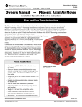
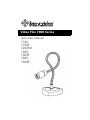
Video Flex 7000 Series
Instruction Manual
7100
7100P
7200HD
7300
7300P
7600
7600P
Video Flex 7000® Series Instruction Manual
Thank you for your purchase of a Ken-A-Vision Video Flex® 7000 series
camera! You have acquired a high resolution solution to any presentation
need, be it classroom or conference room. Images captured by your camera
will be transmitted directly to your TV/Monitor, Projector, or VCR (7100,
7100P, 7300, 7300P,) or through your computer to a Projector, DVR, Flash
Drive or other digital device (7200HD). The 7600 and 7600P may be used
either as an analog/video device, or a digital device or both simultaneously,
giving you the advantages of both formats, and transmitting an image to all
kinds of Output Devices. All images can be shown at full screen!
As you unpack your unit it should include the following parts besides the
camera itself.
7100, 7300
7100P, 7300P
•
Units Formatted for NTSC
Operation
•
Units Formatted for PAL
Operation
•
Appropriated Power Supply
•
Appropriate Power Supply
•
RCA Composite Video and
Audio Cable
•
RCA Composite Cables
•
S-Video Cable
•
S-Video Cable
•
28mm Microscope Adapter
•
28mm Microscope Adapter
•
Discovery Scope Kit
•
Discovery Scope Kit
•
Ball and Socket Head
•
Ball and Socket Head
2
7200HD
•
Attached USB Cable
•
Powered by USB So No Separate Power Cable
•
28mm Microscope Adapter
•
Ball and Socket Head
•
Discovery Scope Kit
•
Applied Vision™ Software CD
•
Applied Vision Manual
7600 - (Same parts as 7100,7300
with following additions)
7600P -(Same parts as 7100P,
7300P with following additions)
•
Units formatted for NTSC
•
Units formatted for PAL
•
USB 2.0 Cord
•
USB 2.0 Cord
•
Applied Vision™ Software CD
•
Applied Vision™ Software CD
•
Applied Vision Manual
•
Applied Vision Manual
If any components are missing, please contact your authorized Ken-A-Vision®
dealer.
Setting up and using Your Video Flex® is as Easy as 1, 2, 3...
1. Connecting the Video Flex® to Power Supply
7100, 7100P, 7300, 7300P, 7600, 7600P:
First prepare your switching (automatically switches from 110v to 240v) power
supply for camera use. Remove it from its packing, and select the appropriate
male plug for your locality. (In USA it is a standard 2-prong plug) Put the 'box'
of the plug in one hand, and then slide the appropriate male plug into position
on the "box". (It will only go on in one direction without excessive force).
3
Now plug the small, round male plug at the other end of the power supply,
into the Video Flex® camera, in the slot marked PWR, in the middle back of
the unit.
Plug the Video Flex® camera unit into your power source. If unit was
purchased or shipped to the country of use, the plug has the correct male
adapter and is rated for the correct voltage.
Push the button on the top of unit and light comes on and your Video Flex®
unit is now powered.
Should you need a replacement power supply, contact Ken-A-Vision or your
dealer. When using internationally, be sure to use the correct AC input voltage
either 110V, 220V, or 240V output voltage. For your Video Flex to operate
correctly, it should be operated at between 5V-16V with a minimum of 500mA.
Substitution or use of non-Video Flex® parts may void your warranty.
7200HD:
This digital camera is powered by the attached USB connected to the unit, and
in order to power the USB Plug must be inserted into the USB port of your
computer. In general it is better to wait until you have loaded the Applied
Vision™ Software on your computer to power up your unit.
2. Connecting the Video Flex® to an Output Device:
7100, 7100P, 7300, 7300P - also the 7600, 7600P if only wishing to use
analog/video output:
Composite Connections;
Connecting the Video Cable (RCA type Composite, yellow is for video, red is
for audio)
Simply connect the yellow video composite connector into the "video-in" on
your TV/Monitor, VCR or Projector (output device). Connect the other end of
the composite cable to the yellow "C-VID" female plug on your Video Flex®
camera unit. (plug is located on back of unit, slightly left of center). If unit is
powered up and red light of unit is on, video image from camera should
appear on your output device.
S-Video Connections:
The S-Video cable is a 4-pin cable which plugs into the rear of your Video
Flex® camera unit. Simply connect S-Video connector into the "S-Video-in" on
your TV/Monitor, VCR or Projector (output device). Connect the other end of
the S-Video cable to the "S-VID" female plug on your Video Flex® camera unit
4
(plug on back of unit, at the far left of center). If unit is powered up and red
light of unit is on, video image from camera should appear on your S-Video
output device.
•
TV/Monitor
Connect the composite (RCA type) yellow video cable or the S-Video
cable from the Video Flex® camera into the "Video In" connector of the
TV/Monitor. If no "Video-in" is available, you may need an RF Modulator
or a VCR recorder. See owner's manual of TV/Monitor for operating
procedures. (Commonly TV/Monitor must be set on "AUX" for auxiliary).
•
VCR (Recorder)
Connect the composite (RCA type) yellow video cable or the S-Video
cable from the Video Flex® camera into the "Video-In" connector on the
VCR. Connect VCR cables from your VCR to TV. See owner's manual of
VCR for operating procedures.
•
Projector
Connect the composite (RCA type) yellow video cable from the Video
Flex® camera into the "Video-In" connector on the video projector.
(Modern projectors rarely have S-Video, but if available, follow normal
connection procedures). See owner's manual of video projector for
operating procedures.
72000HD (Digital Video Device), or 7600, 7600P if operating as a digital
unit:
Prior to connecting the USB cable, you must first install the supplied software.
Please see the Applied Vision™ Software booklet provided with the enclosed
software CD.
Once the software is loaded onto your computer, connect the USB cable
(permanently attached to 7200, cable in box of 7600 or 7600P) to the
computer with the standard rectangle shaped USB plug. With the 7600 and
7600P plug the other end (smaller, more square shaped USB connector) into
the Video Flex® camera in the plug marked USB. (Plug on Video Flex®
located on the back of the unit at the far right end and labeled USB).
Click on the desktop icon for the software, follow simple instructions and
camera should show an image on your computer screen. See Applied
Vision™ Software Manual if there are any problems with an image. You are
ready to go!
Output from computer to Projector, VCR, DVR, Flash drive, CD's and/or DVD
will, most commonly, use VGA (15 pin) cables, but there are other possibilities
5
dependent upon your computer set up.
computer for the operating procedures.
See the owner's manual of the
Note1: The USB cable provides ample power to the camera, no separate
power supply needed.
Note2: On the 7600 and 7600P, if the USB is connected, THE POWER SUPPLY
DOES NOT NEED TO BE CONNECTED. In fact, trying to run a 7600 or
7600P with both USB and power cord connected may adversely affect the
image quality or cause the image to flicker. When the USB is connected, all
plugs on the back of the unit (composite and S-video plus the USB will work
simultaneously without the power cord!
3. Capture and store images:
If you have are using an analog/video unit (7100. 7100P, 7300, 7300P, or
7600/7600P on analog use only, you may record images to a VCR or other
comparable analog unit. If you are using a 7200UM, or 7600/7600P on
digital use, images may be recorded to a computer, DVR, Flash Drive, CD or
similar digital unit using Applied Vision Software. The Applied Vision Software
will allow you to record single images, a sequence of time lapse images, a
time lapse movie, or a movie. Images may also be captured and retained
using the camera function on an Interactive White Board (IWB).
5. Picture quality adjustment
• Brightness/Contrast:
7300, 7300P, 7600, 7600P (in analog mode)
The amount of light can be adjusted using the manual contrast controls
on the base of the Video Flex®. There are two sunburst buttons that allow
you to adjust the brightness. Hold down the desired button until desired
clarity is achieved.
Models 7600, 7600P (in digital mode), 7200UM - brightness and
contrast may be adjusted independently using Applied Vision™ Software.
At the lower left corner of the image find a button entitled "Color Balance"
Clicking on this button will open a set of sliding scales on bottom of
image which will allow adjustment of Brightness, Contrast and Saturation.
Slide these back and forth while watching the image to find the desired
image quality.
•
Positive/Negative Image:
7300/7300P and 7600/7600P
These units have a positive/negative switch located on the base which
allows the video image to be reversed, like film negatives or a darkfield
control on microscopes. This feature is excellent for multi-media
applications and use in forensics. Use the contrast controls to adjust the
contrast while in the negative/positive mode.
6
7600, 7600P (in digital mode), 7200HD
On the 7600/7600P units, the switch on the base can be used even when
camera in digital operation. But additionally the positive/negative image
may be toggled on/off using the Applied Vision™ Software. (If your
version of Applied Vision™ Software does not have this feature you may
have an older version, down load newer version from Ken-A-Vision web
site).
•
Fluorescent control
7300/7300P and 7600/7600P
On these Video Flex® units a fourth button labeled "iris" can be used to
help eliminated the image flicker found with certain fluorescent lighting
conditions. When using this feature with a microscope, it may be
necessary to adjust or filter the light on the microscope, for the correct
amount of light. This can be accomplished with the iris on the microscope
5-hole diaphragm or by using frosted filters. Under prolonged fluorescent
lighting conditions, color may slowly change.
Please note that touching either contrast control button will disable this
capability.
7600, 7600P (in digital mode), 7200HD
Fluorescent control may be found in the Applied Vision™ Software. (If
your version of Applied Vision™ Software does not have this feature you
may have an older version, down load newer version from Ken-A-Vision
web site).
6. Video Flex® Lenses
Your Video Flex comes with a threaded C-mount 8mm lens. Optional lenses
may be purchased separately from Ken-A-Vision, including a 4mm (VF4MM)
for wide angle applications, and 16mm (VF1614), 25mm (VF25MM) or
50mm (VF50MM) to increase focal distance.
You can also use 35mm
camera lenses, provided you have the appropriate adapter. An extension tube
can be added for extra detail magnification. The C-Mount style camera lens
provides a quick and easy method of changing from one lens to another.
•
Changing the camera lens:
A standard 8mm lens is assembled on each camera. To change the lens,
simply extend the lens by rotating in a counter-clockwise rotation until fully
extended. Apply a small amount of additional force in this same direction
to free the lens. Screw on the new lens, and as threading seems to reach
end of natural easy course, apply a small amount of additional force to
lock it in place. Rotate the lens back in a counter-clockwise direction to
ensure it extends, rather than unscrew. If it unscrews, re-tighten in a
7
clockwise direction, adding an additional amount of force to lock it in
place.
7. Focusing:
The Video Flex® uses the patented Quick Focus® C-mount lens. The focusing
ring, located on the camera head, is similar to that of a 35mm camera. The
new ergonomic design makes focusing with one hand a snap. Just a 1/4 turn
of the focus ring adjusts focus from close-up to infinity.
When using the standard 8mm lens, the light will automatically be adjusted for
optimum viewing conditions, depending on the available light and options in
use. When using the optional 16mm manual iris lens (VF16MM), open the iris
until you have sufficient light to show the image on the monitor. Then, adjust
the focus ring until your image is crisp. Once you have a crisp image, you
may want to readjust your manual iris, to achieve the best image possible.
8. Optional Polarizing Adapter:
Polarizing accessories are used for geology, petrology, mineralogy, toxicology,
chemistry, pharmaceutical, medicine, pulp/paper, atmospheric pollution,
ceramics technology, forensic medicine and more.
•
The Microscope Polarizing adapter kit (VFEAPKO) allows you to turn any
microscope into a polarizing microscope. Place the polarizing eyepiece
adapter over the microscope eyepiece and connect the Video Flex, slip the
polarizing film between the slide and the light source, and rotate the
polarizing eyepiece to reveal the polarizing light spectrum.
•
The Discovery Scope Polarizing Filter (VFDSPF) is used with the Discovery
Scope Kit to create a Polarizing Video Microscope. The polarized analyzer
is press fitted into the inner ring of the C-mount camera lens, and the
polarizing film is positioned in-between the guides on the discovery scope
holder and behind the specimen slide. When the analyzer is rotated, the
Video Flex will reveal the polarized spectrum, all without the use of a
microscope!
9. Connecting the Microscope Eyepiece Adapter:
The Video Flex® as shipped came with a 28mm microscope eyepiece adapter
that allows your Video Flex® to be coupled with microscopes or other objects
which have eyepieces. The 28mm adapter included will fit most compound
microscopes. Using the Video Flex® without the adapter will fit most stereo
(dissecting) microscopes (34.5 mm).
8
NOTE: Before installing the microscope eyepiece adapter, measure the size of
the outside diameter of the microscope eyepiece to be sure adapter will fit over
the end of the eyepiece. Remove the rubber eyecup if present.
1. Place the microscope eyepiece adapter over one (if Dual-Headed or
Binocular) of the microscope's eyepieces. If there is a rubber eyecup
on the microscope eyepiece, it should be removed first. If there are
two eyepieces on your microscope, light entering the open eyepiece
will not cause any problems with imaging.
2. Attach the Video Flex® to the eyepiece adapter by gently sliding the
Video Flex® camera head onto the eyepiece adapter, aligning the
microscope adapter with the inside opening of the Video Flex®
camera (inside the knurled focusing ring).
Note: Use only genuine Video Flex® parts and accessories. All Ken-A-Vision
parts provided are made specifically for the Video Flex® and failure due to use
of non-vision viewer parts will void the warranty!
10. Lighting:
Your Video Flex® operates using ambient, room light. If using camera in a
severely darkened room, supplement the light entering the camera by using a
penlight, flashlight or small lamp near the camera, so that there is more local
input light for the camera to work with.
Never point your Video Flex® at direct sunlight. Subjecting the Camera "eye"
to direct sunlight will discolor the filter over the CMOS chip causing aberrant
colors and or permanent focusing problems. It may even destroy the camera's
ability to capture an image.
11. Using the Discovery Scope Kit: (Ken-A-Vision part number VFDS)
• First find the Discovery Scope Clamp provided. One end looks like an
alligator clip and the other end has an open, larger clamp, shaped in a
hemi-circle. Rotate these so that the clamp ends are 90 degrees opposite
each other.
• Attach the Discovery Scope Clamp (by the "alligator" end) onto the neck of
the Video Flex®, approximately 1/2" - 1" down from camera head.
Simply push clamp onto neck (it may require a little force, but be careful)
• Slide the Telescoping Tube into the hemi-circle end of the same clamp.
• Select which attachment you would like to use:
o The tweezer-clamp for the 35mm slides or other items to be held,
o Specimen "Bug" box holder (looks like an American football goal post).
The box will slide between the arms and small notch in box matches
small protrusion on arms of holder.
9
o
•
•
One of the small plastic specimen holder envelopes and the box
holder. The Bags are held by the small slit in the ends of the box
holder.
Now place the shaft of the holder into the small opening located at the
end of the telescoping tube.
Adjust the telescoping tube and attachment holders to position the object
directly in front of the Video Flex® camera lens
Video Flex® Specification Chart
Base
Neck Length
Head
Lens
Magnification
Focal Distance
Resolution
Eyepiece Adapters
Warranty
Triangular Poly-carbonate
25" (63.5 cm)
Ball & Socket
8mm C-Mount 1/4 Quick FocusTM
Approximately 50:1 at 1 (2.5cm) from object
1/4" to infinity
500 lines (7100/7100P, 7300/7300P, 7600/7600P
640 x 480 (7600/7600P Digital)
1920 x 1080 (7200HD)
28mm & Built-in 34.5mm
5 years
10
Video Flex® Accessories
Expand the capabilities of your Video Flex with accessories. Additional
accessories are available on our Web-site at www.ken-a-vision.com.
Replacement Parts
VFDS..................Discovery Scope Kit
VFPSEU..............Discovery Scope Kit 2200
VFPSUSA............Power Supply 1100
VFEA280............28mm Eyepiece Adapter
VFC12AV...........12' Audio/Video Cable
VF8MM..............8mm Lens
Ken-A-Vision has over 65 years of history providing quality products to
institutions world wide. We stand behind our workmanship and offer an
unbeatable warranty. We offer products for education, lesson plan ideas,
technical support and certified microscope repair. If you have questions about
how our repair facility could serve your repair needs, please contact
Ken-A-Vision at (816) 353-4787 or e-mail us at [email protected].
To learn more about our company's products and services please visit our
web-site: www.ken-a-vision.com.
11
Camera complies with Class A and B, part 15 of the FCC Rules.
Use only Ken-A-Vision Video Flex parts. The Power Supply and Charger are
made exclusively for the Video Flex. Failure to use non-Video Flex parts will
void your warranty.
INFORMATION TO THE USER Changes or modifications not expressly
approved by the party responsible for compliance could void the user's authority to operate the equipment.
NOTE: This equipment has been tested and found to comply with the limits for
a Class B digital device, pursuant to part 15 of the FCC rules. These limits are
designed to provide reasonable protection against harmful interference in a
residential installation. This equipment generates, uses and can radiate radio
frequency energy, and if not installed and used in accordance with instructions,
may cause harmful interference to radio communication. However, there is no
guarantee that interference will not occur in a particular installation. If this
equipment does cause harmful interference to radio reception which can be
determined by turning the equipment off and on, the user is encouraged to try
to correct the interference by one or more of the following measures: Reorient
or relocate the receiving antenna and/or increase the separation distance
between the equipment and the receiver, and/or connect equipment into an
outlet on a circuit different from that which the receiver is connected; and/or
consult your dealer or experienced radio/ TV technician for help.
Ken-A-Vision reserves the right to make design improvements and other changes in accordance with the
latest technology. There is no obligation to make changes in products already manufactured. Patents
Pending Copyright 2010 Ken-A-Vision Corporation
5615 Raytown Road • Kansas City, MO 64133 U.S.A.
Tel.: 816-353-4787 • Fax: 816-358-5072
email:[email protected] • www.ken-a-vision.com
INS-VF7