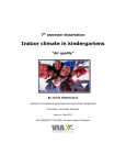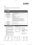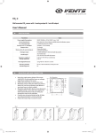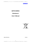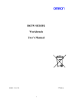
1
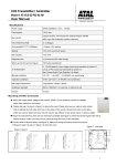
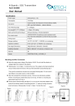
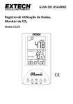
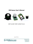
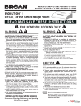
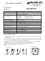
ØLAND A/S
CO2+ Temperature Transmitter
Tel. +45 7020 1911 . www.oeland.dk
E-mail: [email protected]
CVR-nr. 60 99 40 13
Danske Bank 4065 3176141069
PAR-620-CO2
User Manual
Specifications
Power supply
24VAC (50/60HZ 10%), 24VDC
Consumption
2.2W average
Gas sensing element
Carbon Dioxide: Non-Dispersive Infrared Detector (NDIR)
ABC Logic Self Calibration Algorithm
CO2 measuring range
0 2,000ppm
(F2000TSM-CO2-S211T-02)
0 5,000ppm
(F2000TSM-CO2-S211T-05)
0 20,000ppm
(F2000TSM-CO2-S211T-20)
0 50,000ppm
(F2000TSM-CO2-S211T-50)
Accuracy@25 (77 ),2000ppm
40ppm +3% reading
Warm up time for each turning-on
<5minutes (operational)
Temperature measuring range/ Accuracy
0~50 /
Humidity measuring range / Accuracy
5 -95%RH /
Analog output
2 X 0 10VDC
Communication interface
0.5
(25 , 40%-60%RH)
3%RH (25 , 40%-60%RH)
RS-485, 9600/14400/19200(default)/28800 or 38400bps (programmable
selection), 15KV antistatic protection.
Operation conditions
0~50 (32~122 ); 0~95%RH, non condensing
Storage conditions
-40~70 (-40~158 )
Net weight/ Dimensions
105g
Installment standard
65mm 65mm(2” 4”) wire box, or hang on a nail
IP rate
IP30
100mm 80mm 28mm
Mounting and Wire Connection
Notice the supply power voltage of the transmitter: 24VAC. Do not install the transmitter on voltages higher than marked
on the transmitter.
Following step 1 to 4 in figure. 1 to remove the cover. First, prepare a flat head screwdriver and put it deep inside of the
hole on the top of the transmitter housing following step 1. Then slant the screwdriver and open the cover gently following
step 2. Do not mount it near diffuser or any steam source, in direct sunlight.
Mount the main part first, there are two dimensions available (see figure 2). Place the transmitter against the wall at
desired location; make sure wires can be passed through the notch on the back board.
Connect wires to terminal strips, (see fig.3). Make sure wiring connection correct and secure.
Follows the step 5 to step 8 in figure 4 to close the cover.
Fig.2 wall plate
Fig.1 open the cover
Ballerup
Hovedkontor/produktion/salg/lager
Energivej 3-7, 2750 Ballerup
Fax (+45) 44 53 10 51
Aabenraa
Produktion/salg
Kathale 41, 6200 Aabenraa
Fax (+45) 44 53 10 51
Vejle
Salg/lager
Sadelmagervej 15, 7100 Vejle
Fax (+45) 44 53 10 51
Medlem af
Dansk Ventilation
brancheforening for et bedre indeklima
ØLAND A/S
Tel. +45 7020 1911 . www.oeland.dk
E-mail: [email protected]
CVR-nr. 60 99 40 13
Danske Bank 4065 3176141069
Fig.4 close the cover
Fig. 3 wiring diagram
F2000TSM-CO2-S211T
8
A
7
6
5
B
4
CO2
T
3
2
1
Gn
G+
T&CO2
COM NO1 OUT2 OUT1
RS-485
1mm
2
6
24VAC/VDC
5
7
8
Connection and output
Connection Terminal
Function
Electrical Data
1
G+
Power (+)
24VAC/24VDC +
2
G0
Power ground (-)
24VAC/24VDC
3
OUT1
Analog output 1 (+)
0~10VDC output for both CO2 and temp
(CO2 500ppm~1,500ppm and temp 23℃~29℃, lower and higher limits for
both CO2 and temp are adjustable)
4
OUT2
Analog output 2 (+)
0~10VDC output for temp 23℃~29℃
(Both lower and higher limits are adjustable)
5
NO1
6
COM
7
B
8
A
ON/OFF output
Rated switching current 3A (240VAC/30VDC), resistance load;
On/off output for CO2, 900ppm, also adjustable
RS485 interface
9600/14400/19200(default)/28800 or 38400bps
(Programmable selection), 15KV antistatic protection.
Important Instructions:
1. About analog output 2: combined output for CO2 and temp. The higher voltage output is effective at a certain time. E.g.: At a
2.
3.
4.
a.
b.
c.
certain time, voltage value for current CO2 is 5DVC and voltage value for current temp. is 4.5VDC, then analog output 2 would be
5VDC instead of 4.5VDC.
Don’t shake or hit the transmitter too much in shipment or in mounting to protect the internal infrared CO2 sensor from any
damage and excursion of infrared receiver.
When open the cover of the transmitter, you'll see one PCB board mounted over another bigger PCB board. This upper PCB
board is loaded with CO2 sensor. Don’t uninstall the upper board from the below one without instruction from our engineers, in
order not to cause any damage to the CO2 sensor.
When
First use CO2 transmitter, or
Reuse CO2 transmitter after a long time unused or
CO2 measurement is proved to be incorrect (by comparing with the measurement of other accurate CO2 products, or put the
transmitter outdoors and its measurement is away from the range of 350ppm~450ppm, which is the normal ambient CO2 level
range.)
TM
Then let ABC Logic Self Calibration System work as follows:
TM
Keep the CO2 transmitter energized continuously for at least 2 days to let CO2 sensor’s ABC Logic self-calibration system
operate properly. After more than 2 days’ calibration, if the measurement (indicated by the analog output) of the CO2 transmitter
still exceeds over the accuracy, you need to let it self-calibrated for a longer time. Here’s the typical 14-day calibration solution:
During a 14-day period, place the CO2 transmitter twice in outdoors or unoccupied places where CO2 level is around 400ppm.
Each time let it be there for more than 4 hours and then check the CO2 measurement via the analog output. If the CO2
measurement is in its accuracy limit, it indicates the measurement is right.
Notice:
a. Use of cellular telephones or radio transceivers with two feet of the sensor during calibration process could cause sensor
interference, calibration errors and affect sensor accuracy. Please refrain from using these devices during sensor calibration.
b. When checking the analog output, please avoid breath out directly to the CO2 transmitter. It’s better to connect the output
terminals withBallerup
the Extending Wires with length of more
than 1 meter. When the CO2
transmitter becomes stable after more than
Aabenraa
Vejle
Hovedkontor/produktion/salg/lager
Produktion/salg
Salg/lager
10 minutes turning-on,
check the analog output through
the extending wires. That’s
because people’s breath influences
CO2
Medlem af
Energivej 3-7, 2750 Ballerup
Kathale 41, 6200 Aabenraa
Sadelmagervej 15, 7100 Vejle
Dansk Ventilation
level.
Fax (+45) 44 53 10 51
Fax (+45) 44 53 10 51
Fax (+45) 44 53 10 51
brancheforening for et bedre indeklima