1
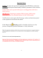
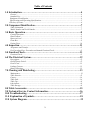
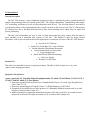
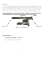
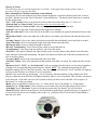
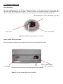
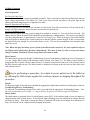
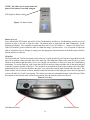
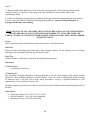
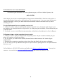
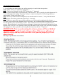
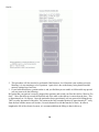
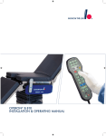
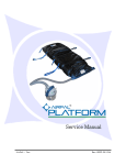
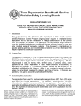
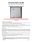
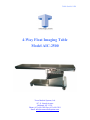
Table Serial # 1028 4-Way Float Imaging Table Model AIC-2500 Tower Medical Systems, Ltd. 917-11 Lincoln Avenue Holbrook, NY 11741 Phone: (631) 699-3200 Fax: (631) 699-3201 Email: [email protected] Important Notices Caution: To ensure safe operation of equipment, please READ these instructions Completely and keep this manual readily available to personnel for future reference. Caution: Table can be operated without power cord plugged into outlet due to battery back up. IMPORTANT: Tampering or opening of table enclosure without proper authorization from Tower Medical Systems, Ltd will VOID warranty. Carefully observe and comply with all warnings, cautions and instructions placed on the equipment or described in this manual. In this Manual, the Warning symbol is intended to alert the user to the presence of important operation, maintenance, or safety instructions. Note: The application techniques outlined in these instructions are the manufacturer’s suggested techniques. The final disposition of each patient’s care as related to the use of this equipment rests with the attending physician. This device is to be used by trained personnel only. Important: Please keep the table plugged in at all times and the power switch in the “ON” position, (“I”) when the table is kept stationary. Although the battery will last for up to 24 hours without line power, it is recommended to do so in order to avoid battery drainage. 2 Table of Contents 1.0 Introduction………………………………………………………………….4 General ……………………………………………………………………………………………………………4 Intended Use………………………………………………………………………………………………………4 Equipment Classification………………………………………………………………………………………...4 Specifications and Operating Specifications…………………………………………………………………..5 Glossary of Terms………………………………………………………………………………………………….6 2.0 Component Identification…………………………………………………...7 Table Orientation………………………………………………………………………………….....................7 Model Number and Serial Number…………………………………………………………………………….7 3.0 Basic Operation……………………………………………………………...8 Control Operation………………………………………………………………………………………………..8 Hand Control……………………………………………………………………………………………………..8 Return to Level…………………………………………………………………………………….....................9 Float Box………………………………………………………………………………………………………….9 Patient Facts…………………………………………………………………………………………………….10 4.0 Inspection…………………………………………………………...............11 Acceptance and Transfer……………………………………………………………………………………….11 Pre-Procedure/Post –Procedure and Annual Function Check……………………………………………11 5.0 Function Check…………………………………………………..................11 Function Check………………………………………………………………………………….......................11 6.0 The Electrical System……………………………………………………....12 Description……………………………………………………………………………………………………….12 On/Off Power Switch……………………………………………………………………………………………12 Power Cord………………………………………………………………………………………………………13 Leakage Current………………………………………………………………………………………………...13 Battery Charging………………………………………………………………………………………………..13 7.0 Cleaning and Disinfecting………………………………………………….13 Maintanance……………………………………………………………………………………………………...13 Table Exterior……………………………………………………………………………………………………13 Casters……………………………………………………………………………………………………………14 Table Pad………………………………………………………………………………………………………...14 Table Top…………………………………………………………………………………………………………14 Lubrication……………………………………………………………………………………………………….14 Table Storage…………………………………………………………………………………………………….14 8.0 Table Accessories…………………………………………………………...15 9.0 Technical Service Contact Information…………………………………...16 10.0 Troubleshooting…………………………………………………………...17 11.0 Explanation of Symbols…………………………………………………...18 12.0 System Diagram……………………………………………………………19 3 1.0 Introduction General Description The AIC-2500 features a large radiolucent imaging area that is controlled by both a portable hand held control, and positioning float box located on the table. The Height Adjustability, Trendelenberg Movements, X-Y Positioning, and Return to Level are all performed by these devices. The free-float feature is activated by a push-button release on the positioning float box, which is located on the accessory rail. The X-Y Movements are vibration free due to the High Precision Heavy Duty Linear Bearings used, which allow for stable and precise positioning. The table can accommodate any style C-Arm, its sleek design and heavy duty castors allow the table to move smoothly even at maximum load capacity of 500 Lbs. This tabletop is ideal for Image Guided Procedures, such as pain care and cardiovascular applications. Listed below are some of the AIC-2500 features: Free Float X-Y Tabletop Sturdy Low Profile Base for C-Arm Clearance Smooth Motorized Positioning Movements Comes Standard with Accessory Rails Large Imaging Area Quick and Efficient Patient Positioning Extra Low Height Return to Level Feature Intended Use This table is not intended for invasive surgical procedures. The table is ideal for pain care, x-ray, and cardiovascular imaging procedures. Equipment Classification: Agency Approvals: UL Classified Medical Equipment under UL 60601-1 First Edition. CAN/CSA C22.2 No. 601-1, and IEC 60601-2-32 First Edition Protection Against Electrical Shock-Class I equipment(Sub-Clause 2.2.4) with Type B Applied Part (Sub-Clause 2.1.24) Protection Against Ingress of Liquids (Clause 5.3)-IPX0(Ordinary) per IEC 60529 Equipment is not suitable for use in the presence of a flammable anesthetic mixture with air or with Oxygen or Nitrous Oxide (Clause 5.5) Mode of Operation of equipment-Intermittent Operation (The duty cycle lift is 30 seconds on and 1 minute off, and for the Tren (tilt) movement it is 30 seconds on and 1 minute off.) 4 Specifications The AIC-2500 Imaging Table is designed to hold up to 500 pound patient load (including all accessories) in the proper procedural position at any point within its physical range, as mentioned above. The table has a height range of 29 inches with the 2” cushion to 41 inches with the 2” cushion. The width of the table top is 24 inches. The length of the table top is 87 inches. The Trendelenberg range is +/- 15 degrees. The horizontal travel (xmovement) of the AIC 2500 is +/- 20 inches. The vertical travel (y-movement) is +/- 10 inches. The maximum deflection of the table top with a full load is less than 1 inch at the cantilever end. The top has a radiolucent equivalency of less than 1mm of aluminum. The input power requirement is 120 Vac, 60 Hz, 6 A in order to meet international requirements as indicated on the table label. The table can be operated under battery power. . The expected working life of a fully charged battery is approximately 5 hours at a 10% duty cycle. Hand Control Float Box Pedestal End Cantilever End Figure 1.1-AIC-2500 Imaging Table Operating Specifications Temperature Range: 0C to 40C (32F to 104F) Relative Humidity: 30-75% non-condensing Barometric Pressure: 700 kPA to 1060 kPA 5 Glossary of Terms: The following terms are used throughout this User Guide. A thorough understanding of these terms is necessary to properly operate this table. Basic Assumptions of Patient Orientation on the tabletop: Our glossary of terms and technical procedures assume the patient is oriented with their head at the “Front of the table” and their feet at the “Rear of the table” as described below. The hand control functions are oriented for this position only. “On” / “Off” Switch: Refers to the fuse inlet on the pedestal end of the table, On is “I”, Off is “O”. “Pedestal End” or “Rear of table” indicates the power cord end of the table. “Cantilever End” or “Front of table” indicates the opposite end of the rear of the table. “Pedestal” refers to the main column structure that supports the tabletop. “Left side of the table” refers to the left side of the table as you stand by the pedestal end and look down at the table. “Right side of table” refers to the right side of the table as you stand by the Pedestal end and look down at the table. “Locking Castors” refers to the wheels and castors on the table that individually swivel and lock as needed. “Lower the table” refers to lowering the height of the table down toward the floor. “Raising the table” refers to raising the height of the table. “Reverse Trendelenberg” refers to moving the cantilever end of the table up. “Trendelenberg” refers to moving the cantilever end of the table down. “Float Box” is the panel of buttons and lights located on the Accessory Rails at the pedestal end of the table, which indicates desired table positioning. The panel will function on either side of the table on either the side rails or auxiliary clamp. “Accessory Rails” refers to the rails along both sides of the table. “Auxiliary Clamp” refers to the miniature rail that mounts to the table via clamp. The clamp locks the rail into place. “Return to Level”, “RTL”, or “Level the table” refers to returning the table top to a level position regardless of height. The corresponding hand control button is labeled “RTL”. By continuously depressing the RTL button the tabletop will level itself into position. Once the tabletop is leveled, the “Level” indicator will light up in Green on the Float Box to confirm it is at a level position. “Level” refers to the table top positioning. “Level” position is when the tabletop is flat, parallel to the floor. The green indicator on the float box will light up when the table is at a level position. This will allow movement in any direction. If the table is not level, the operator will only be able to move the table “left to right or (YMovement)” as a safety precaution. “Both” refers to simultaneous “Head to Toe” or “X Movement” and “Left to Right” or “Y Movement”. “Head/Toe” or “X Movement” refers to head to toe movement only, the left right option will be locked. “Left/Right” or “Y Movement” refers to left right movement only; the Head to Toe will be locked. “Head/Toe Lock” when lit on the float box, the trendelenberg positioning is possible because it is engaged. If it is not lit, the top can be moved slightly either in the x or y, position when it is locked and Trendelenberg is then able to be used. 6 2.0 Component Identification Table Orientation The major components of the AIC-2500 are illustrated in Figure 1.1. The patients head can be located at either end of the table depending on the procedure. Therefore, the table is described as having a Pedestal End and a Cantilever End. The On/Off Switch, and Power Cord Socket are located at the Pedestal End of the table. Fuse Location (6 A, 250 V, Time Delay Type only) “On”/”Off” Switch Power Cord Figure2.1-On/Off Switch and Power Cord Socket Model Number and Serial Number The serial number is printed on the identification label on the Pedestal End of the base. Power Cord Receptacle/ Serial Number “On”/“Off” Switch/ Fuse Terminal for the connection of Potential Equalization Conductor Figure 2.2-Serial Number/Identification Number 7 3.0 Basic Operation Control Operation For Use with Line Power Plug the Power Cord into a properly grounded receptacle. Refer to the label at the Pedestal End of the base for input voltage requirements. (See Figure 2.2) Turn on the Power Switch and observe the green light on the control panel indicating that power is applied to the table. Mode of Operation on Line Power The duty cycle lift is 30 seconds on and 1 minute off, and for the Tren (tilt) movement it is 30 seconds on and 1 minute off. (This is the time it takes for these movements to be performed) For Use with Battery Power Ensure that the battery has been properly charged as outlined in Section 5.0. Turn on the Power Switch. The Battery Status LED on the hand control should be green indicating a charged battery. The expected working life of a fully charged battery is approximately 5 hours at 10% Duty Cycle. While in storage it is desirable that the table be plugged in and the power switch turned on so that the batteries remain charged. If this is not possible, the batteries must be charged for at least three hours a week. This can be accomplished when using the table under line power. Note: When charging the battery, power switch of the table must be turned on. It is also required to depress the Height and Trendelenberg functions independently. This must be done in order to assure the battery charge is initiated. The battery will not charge unless movement is made. Hand Control: The hand control operates the Height, Trendelenberg, Reverse Trendelenberg, and Return to Level functions. It is a low voltage Hand Control with functions clearly labeled. (See Figure 3.1) The Hand Control should be plugged into the receptacle labeled “Hand Control” receptacle located on the front side of the pedestal end of the table, directly under the top. The Hand Control is intended to be hung on the side rails on either side of the table when not in use. Prior to performing a procedure, be certain to secure patient on to the table top by utilizing the table straps supplied to avoid any injuries or slipping throughout the procedure. Height: To adjust the height of the table press and hold the appropriate height button until the desired height is achieved. Trendelenberg/Reverse Trendelenberg: To adjust the Trendelenberg position of the table, press and hold the appropriate Trendelenberg button. Note: when the Trendelenberg tilt is within +/- 1 degree of level the green level indicator light will illuminate. Battery Status: The hand control is equipped with a bi-colored battery status LED. If the indicator light is green, the battery is charged and the table is ready for use. If the indicator light is blinking green, the table must be charged because the battery is dying. If the light is Orange the battery is dead and will need to be recharged for a minimum of 3 hours. See Section 6.0 for complete battery charging instructions. 8 NOTE: The table can be used under line power if the battery is not fully charged. LED Light for Battery Status Figure 3.1- Hand Control Return to Level: Press and hold the RTL button, this will level the Trendelenberg and Reverse Trendelenberg position to a level position in order to be able to float the table. The button must be depressed and held continuously for the function to complete. The controller considers the table to be level if it is within +/- 1 degree of 0 degree level. If the RTL button is pressed while the table is within this range, it will not move. If it is required to adjust the table to a position closer to 0 degrees, simply press the appropriate function button on the hand control until the desired position is achieved. Float Box: The Horizontal and Vertical movement of the table top is made possible by the float box suspended from the side rail or auxiliary clamp on either side of the table top. The illuminated light on the panel for the Level and Head toe lock indicate that the table is level, at a 0 degree tilt, and that it is ready to be used for Trendelenberg positioning. To use the float box, slide it onto the side rail or auxiliary clamp on either side of the table and plug it into the receptacle labeled “Float Box”. The receptacle is located on the front of the pedestal end of the table, underneath the top. To lock the float box into place, you will need to turn the knob located under the panel. The Panel includes two activation or release buttons located on both sides of the hand grip, these must be depressed to move the table for X and Y movements. This feature prevents any unintended motion of the table top. When the buttons are released the table will lock into position once the desired position is achieved. Figure 4-Float Box Push Button Release Push Button Release 9 Cont’d… Figure 4.1- Hand Control and Float Box Receptacles Patient Facts: When a patient is on the table there a few fact to know prior to commencing with necessary procedures: 1. If the table is not able to be plugged into an outlet throughout the duration of the procedure, be certain that the table is adequately charged in order to avoid any delays. 2. Always be careful that the patient gets on and off the table in the center of the top. In other words, do not allow the patient to sit on the tip of the table. 3. Be certain that the patient is securely strapped into position, if it is required. 4. If the table height will need to be adjusted from the lowest position, prior to raising the table top, move the float box dial to “Head to Toe Only”, and move the top so that it is centered on the base. At that point is safe and easier to raise the top. Once the top is at the desired height, you may manipulate the top to where you need it. This is to assure the motors and columns do not burn out prematurely. 10 4.0 Inspection Acceptance & Transfer Upon receiving your AIC-2500 Imaging Table, remove the table from the shipping crate following the unpacking instructions. Visually inspect all surfaces for freight damage. Check each castor for proper rolling operation. NOTE: If any freight damage is incurred, it must be reported to the freight carrier immediately upon delivery. It is the responsibility of the recipient to make any freight damage claims. Read through the user manual to familiarize yourself with the AIC-2500 functions. Place the AIC-2500 in an area with a minimum of 4 feet of clearance on all sides. Perform the Function Check; see Section 5.0 to assure everything is working as it should. Complete and mail back warranty information. Pre-Procedure/Post Procedure and Annually Functional Checks Inspect and test the table as described in the FUNCTION CHECK section 5.0 Thoroughly clean the table as described in the Cleaning section of this manual. Pay special attention to the cleanliness of the controls as excessive soil can effect functionality of the table components. Inspect the power cord for cuts and tears and damage to the connector. Check to see that all fasteners are tight.(Hand Control and Float Box Receptacle) 5.0 Function Check Perform all checks in this procedure. If you have any questions please feel free to contact us at (631)699-3200, Monday-Friday 9AM-4PM EST. For a complete definition of reference terms used in this procedure, please refer to the “Glossary of Terms” on pg. 5 of this user guide. Function Check: 1. Plug in the Hand Control into the designated location. 2. Plug in and tighten the Float Box into the receptacle labeled “Float Box” at the front of the Pedestal end of the table, directly under the top of the table. (Refer to step 5 for remaining instructions) 3. If the table is going to be used under Battery Power, ensure that the battery has been properly charged and that the “Battery Status” LED on the hand control is green when the “On/Off” power switch is on. Please note that if the battery is being charged, Height and Trendelenberg movements must be made in order to engage the battery and initiate the charge. 4. If the table is going to be used under line power, plug in the power cord into an appropriate “Hospital Grade” outlet and turn on the main “On/Off” power switch. Note: The switch is illuminated when the AC power is turned on. Note: If the table is not going to be moved, it is recommended that the power cord always be plugged in and the “On/Off” power switch be turned on. This will ensure that the battery will always be charged in the event of a power outage or if the table should need to be moved. 11 Cont’d… 5. Float Box: 5a. Slide panel onto the desired side rail into position. 5b. Tighten the panel onto the rail by turning the knob located underneath it. 5c. Once it is plugged in the “Level” light should be illuminated green, to indicate that the table is at a 0 Degree tilt. 5d. To test for proper engagement with the top, depress the side release buttons and move the table top both in the “X” and “Y” directions to familiarize yourself with the movements in addition to testing it. Please refer back to pg. 5 for definitions regarding the directional knob on the panel, in order to know what movements will be enabled during use. 6. Hand Control Check: 6a. Press and Hold each of the Height buttons on the hand set to assure the table moves up and down respectively. 6b. Press and Hold each of the “Tren” buttons on the handset and observe the Cantilever end of the table move either up or down respectively. 6c. If your unit is equipped with a battery backup is on your table check to see that the LED light in the top left corner is illuminated green, indicating the battery is fully charged. (refer to pg. 7 for battery status indications) 6d. Disorient the tops’ position by tilting it approximately 5 degrees, either in the Trendelenberg or Reverse Trendelenberg Position. Press and Hold the “RTL” button. (Return to Level) Observe that the table top returns itself to the 0 degree position. 7. Synchronization Check: This is important because when the table is in transit to a facility the table is not plugged in, the batteries may be depleted or beginning to drain upon arrival. The batteries will stay charged for an ample amount of time, but the table MUST be plugged in and the power switch in the “On” position upon arrival. The synchronization of the table must be checked in order to verify the memory is still as it should be, and that the two columns that allow the table movement are working simultaneously. If you find that the return to level is not working correctly or if the table is not moving properly in all directions (i.e Height, Trendelenberg, and RTL) please call us immediately so that we can further diagnose the problem and assist in getting this table up and running as soon as possible. (Please see troubleshooting section for additional details) 6.0 The Electrical System Description The electrical system provides control of all the table functions and is comprised of a Power Cord, and On/Off Power Switch, Wire Harnesses, two Power Supply’s, Hand Controller, Float Box, various electromechanical actuators, Two Stepper Motors, and two 24Vdc batteries. The electric motor driven actuators manipulate the height, and Trendelenberg Positioning via the hand control. Drawing Number 2500-1 is the electrical Wiring Diagram for the AIC-2500. The input power requirement for this table is 120 Vac, 60 Hz, 6 A as indicated on the UL Label. Drawing Number 2500-2 is the Diagram System for the 120 Vac, 60 Hz, 6 A AIC-2500. On/Off Power Switch The On/Off Power Switch is located on the Pedestal end, at the base of the table (See figure 2). When the table is plugged in and the switch is in the On position (1 depressed), the table is powered on. The float box LED lights will be illuminated, even if the table is running off the battery power. Note: Please be certain to check if the power switch is in the “ON” position to assure the table is in fact working on Line Power. 12 Cont’d… Power Cord Utilizes a UL Listed detachable power cord, 3 wires, type SJTW or equivalent, 14 AWG min., rated 300 V min., provided with a hospital grade type plug 5-15P configuration for 120 Vac application. The Power Cord can be connected to the table at the IEC 60320 power entry socket located at the base of the Pedestal End near the On/Off Switch. Leakage Current The AIC-2500 Table is designed and tested to not exceed 300 A of Enclosure Leakage current (in a single fault condition, UL 60601-1). Note: Enclosure Leakage current values below the 300 A threshold are considered acceptable per UL 60601-1 Electrical Safety Standards. Battery Charging The AIC-2500 contains two 24Vdc batteries, one that functions as a lock for the Sylenoid (X and Y functions), and the other that functions the Height and Trendelenberg positions, as well as the level light and X lock light. When the battery status LED light on the hand control is blinking Green, the battery needs to be charged. To charge the batteries, simply plug in the power cord into an appropriate “Hospital Grade” outlet and turn the power switch on, as well as depressing any button on the hand control for at least 5 seconds. At this point the battery has initiated the charging process. While in storage it is highly recommended that the table be plugged in and the power switch turned on so that the batteries remain charged at all times. If this is not possible, the batteries MUST be charged for at least three hours a week. This can be done by using the table under line power. To ensure proper battery function, it is suggested batteries be charged for at least three hours within the first 48 hours of use. The battery Status LED on the hand control must be illuminated Green when the table is on. The batteries should be replaced every 5 years or when they fail to hold a charge. Batteries MUST be replaced or disposed by a qualified technician or field representative of Tower Medical Systems, Ltd. 7.0 Cleaning & Disinfecting Maintanance The following areas are to be cleaned as often as possible in order to assure proper functionality of the table as well as keeping with safety and health of both patients and technicians. Table Exterior-Sheet Metal Skins Casters-Wheels and Castors Table Pad Table Top When cleaning and disinfecting the AIC-2500 we recommend the following: Table Exterior: 1. The exterior surface should be wiped clean regularly with a damp cloth of mild detergent solution and wiped dry with a soft lint free cloth. Note: Do not wipe any interior components, they are to remain lightly coated with oil at all times. 2. Care should be taken to avoid exposing the table to excessive moisture. 13 Cont’d… 3. Blood and other fluids should not be left on the table for long periods of time. Special cleaning will be required to remove it. Typically, white vinegar and water solutions are used to rid the table of any contaminating fluids. 4. Commercial cleaning compounds such as Stainless Steel Magic followed by hand buffing the table exterior, is done to correct the stainless finish from staining and discoloration. Any use of Methylated spirit or Isopropyl alcohol may cause staining. NOTE: DO NOT USE ANY CLEANERS THAT CONTAIN BLEACH ON ANY OF THE SURFACES MENTIONED ABOVE, AND NEVER POUR LIQUID DIRECTLY ONTO THE TABLE. BE CERTAIN TO DRY ALL SURFACES THOROUGHLY AFTER CLEANING THE TABLE IN ORDER TO PREVENT RUST. Casters: Casters should be cleaned and disinfected in the same manner as the Table Exterior. Table Pad: Remove Pad from the tabletop and clean with a mild detergent solution. Do not submerge into water. Rinse thoroughly with clean damp cloth and dry with lint free cloth. Table Tops: Disinfect surfaces of table tops according to standard hospital procedures. Lubrication 1. Table Exterior No Lubrication Necessary 2. Table Interior The translation and height adjustment sliding mechanisms of the AIC-2500 Imaging Table require periodic lubrication. These sliding mechanisms are called bearings. There are a total of eight bearings and each should be lubricated once a year and will be done during preventative visits by a qualified technician or field representative of Tower Medical Systems, Ltd. All other components are lubricated at the factory and will not need additional lubrication throughout the life of the table. Table Storage Temperature Range: 0C to 49C (32F to 120F) Relative Humidity: 10 to 100% non-condensing Barometric Pressure: 700 kPA to 1060 kPA 14 8.0 Table Accessory Options Battery Back Up System (PN-1520-301): This can be added at any point in time and can be done in the field. Intended for facilities that require movement and replacement of the table throughout the facility. Battery Back Up System MUST be installed by a qualified technician or field representative of Tower Medical Systems, Ltd. Radiolucent Arm Board (PN-1520-302): This item is placed between the tabletop and the pad and is held in place by the patients weight. The armboard is carbon fiber surface with 2” pad. It can be used on either side of the table, right or left. IV Pole (PN 1520-303): Slow-descending stainless telescoping top pole. Outer tube is 7/8"; inner tube is 11/16". 2-hook top. Stainless ½” mounting pin for solid, secure attachment to beds, gurneys and medical carts.60” fully extended;33” compressed. The maximum weight for each hook is 2.2 pounds. Auxilary Clamp (PN 1520-304): The auxiliary Clamp mounts where needed on the cantilever end of the table to provide an additional area to mount either the Float Box, IV Pole, or any other accessory necessary for the procedure at hand. Table Pad (PN 1520-305): The pad is made of Herculite® Sure-Chek Lectrolite® Comfort fabric. The foam is high density to help keep patients from bottoming out and well as to the patient a sense of comfort throughout the procedure. The pad is ideal for short to medium length procedures. 15 9.0 Technical Service Contact Information For detailed repair information or to order replacement parts, call Tower Medical Systems, Ltd: (631) 699-3200 Our Technical Service line is available Monday-Friday between 9AM and 5PM. Please be certain to leave a message after business hours, and we will return your call as soon as we can. Leave your name, facility name, contact information, as well as your table model and serial number so that we can better assist you when returning your call. To order Replacement Parts or to schedule a service visit: 1. Call, fax or email us with your model number and part requested. If you do not know what the part is you may send us a part description and we will get back to you with pricing and availability. Please indicate the part is a Replacement. 2. To schedule a service visit, follow the same instructions as listed above, but indicate it is a Service Request. To Return an item or to Send a part here for us to repair: 1. Call, fax or email us with your model number and part in question. If you are unable to identify the part please call us and we will assist you further. 2. We will provide you with an RGA number (Returned Goods Authorization) or RA Number (Repair Authorization). 3. Whether you are returning or repairing an item please clean and disinfect the item prior to shipment. 4. We will notify you of any additional costs prior to repair of an item, upon approval we will repair and return the item to you. Our fax Number is (631)699-3201 and our email address is [email protected] . You may also contact us via our website at www.towermedicalsystems.com, and click on the contact us icon. 16 10.0 Troubleshooting Checklist 1. If you find that your table height is not working properly or is stuck in the down position: Step1-Double check to see if the table is plugged in. Step2- Check to see if the table is in the “On” Position, the “1” depressed. This is to assure that the battery is not drained due to no line power. This is caused by the table shipment or if it is moved throughout the facility. The battery backup is expected working life of a fully charged battery is approximately 5 hours at 10% Duty Cycle. Step3-Once steps 1 and 2 have been completed, lower the table until it is about a ½” away from the bottom. Then hold the down button on the hand control for 15-30 seconds. Step4-If the above steps still do not rectify the problem, you will then need to synchronize the columns. You were given with your table shipment a box of extra fuses, and an additional hand controller that is different from the one that comes standard with your table. That controller is the one used for the synchronization process. This malfunction is caused by the battery draining to the point where the memory functions have been deleted, which is why it is very important to always have the batteries fully charged. This is done by keeping the table plugged in as often as possible, and having the table turned on with the “1” depressed. IMPORTANT: Prior to synchronizing the columns, please call Tower Medical Systems, Ltd. for a walk through of the procedure. This process will erase all memory settings and may cause your table to not function properly if it is not done correctly. The Steps to synchronize are as follows: 17 Cont’d… 2. This procedure will also need to be performed if the Return to Level function is not working correctly. Meaning, it is not returning to a level position. Again, this is due to the battery being drained and the memory settings have been lost. 3. If your table should have a patient on the it, and you find that you are unable to lift the table top upward, you may want to do the following: Be certain that your patient is securely strapped into position, and switch your float box dial to “Head to Toe Only”. Move the table top toward the Pedestal end of the table so that the top is centered on the base. This is approximately at -10 degrees. Once the patient has been repositioned, you may proceed in lifting the top. This is a safety precaution of the table. The patient at the fully extended position is approximately 87” away from the base and the motors will in time, overwork themselves with that much of a strain. In order to lengthen the life of the electrical system, it is recommended that the lifting is done in this way. 18 11.0 Explanation of Symbols Protective earth Equipotentiality Attention, consult Accompanying Documents Off (Power: Disconnection from mains) On (Power: Connection to the mains) Type B Applied Part Indicates Model AIC-2500 is approved according to UL and cUL regulations. 19