1
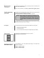
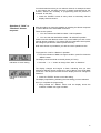
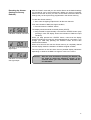
DIMMERPACK DDE Actor
ACTOR DDE
USER’S MANUAL
Introduction
The New DDE Actor is of compact and robust construction using DMX-512
(1990) and analogue technology. It combines high quality and reliability and
it is offered at a very competitive price. On the front panel of the dimmer
there are preset sliders and master control. The units are designed for 19”
rack mounting either οn fixed installations or on touring racks. The dimmer
packs can be controlled with analogue input 0/+10V or with DMX-512
(1990). The user has the capability of selecting whether the dimmer will
hold or blackout the last DMX-512 data in case of failure of serial
connection. The unit has twelve factory set chasers with capability of
selecting the dimmer level and the speed. The user can also select one of
the three waveforms (LAW) for each channel and at the same time can set
Preheat Levels and Soft Start time for each channel, using the keyboard
and the display mounted on the front panel. The keyboard is also used to
select the DMX-512 start address, while the display shows the correct or
fault DMX signal condition. The power supply is connected on a 6-pin plus
ground connector. The dimmer is supplied with Schuko outlet sockets.
AVAB-CAC would like to thank you for choosing the DDE Actor and assures
you that this is an amazing tool for lighting control applications. We believe
that using this dimmer will be very exciting for you.
For safe and correct operation, please read the instruction manual very
carefully, before using this dimmer.
AVAB-CAC
Any reproduction by means or whole of this user’s manual in any way is prohibited without the written consent of AVAB-CAC.
2
AVAB-CAC.reserves the right to change or alter any information contained in this manual without prior notice.
Ιndex
Precautions & Operation Notes
Introduction
Before Installation
Installation
After Installation & Power Supply Connection
Electrical Installation
Operating Voltage
Power Supply Connection
Maximum Power Consumption
Load Connection
Introduction
Load types
Outlet sockets
Distribution of the three phase power supply
Dimming Control
Introduction
Analogue Control
Digital Control
On-board Control Panel
Automatic Power Control
Factory chasers
Activation of a chaser
Activation of another chaser
Setting another rate of speed to a chaser
Setting another lighting level to a chaser
Deactivation of a chaser
Useful Notes
Table of the 12 Factory Chasers of the DDE ACTOR
Dimmer Programming Introduction
Indication of DMX-512 signal condition
DMX-512 Start Address
Law Selection
Preheat levels
Soft start
Selection of “Hold” or Blackout” dimmer response
Resetting the dimmer to its factory settings
Τechnical specifications
Page 4
Page 4
Page 4
Page 4
Page 4
Page 5
Page 5
Page 5
Page 6
Page 6
Page 6
Page 6
Page 6
Page 6
Page 7
Page 7
Page 7
Page 7
Page 7
Page 7
Page 8
Page 8
Page 8
Page 8
Page 8
Page 8
Page 9
Page 9
Page 10
Page 10
Page 10
Page 11
Page 12
Page 13
Page 14
Page 15
Page 16
3
Precautions and
Operation Notes
Introduction
• Please, read this instruction manual very carefully.
• In case that something is not clear enough in this manual, please
contact your local supplier.
• The dimmer installation should be made by a qualified person.
Before Installation
Attention: The dimmer should be placed in a dry location with low
levels of humidity and ambient temperature below 35◦C.
• Decide on the installation location.
• Make sure that the supply cable is connected to a mains switch and
the appropriate circuit breaker, according to the total dimmer load.
• Check that the mains switch of the electrical distribution board is set at
the OFF position.
Installation
• In case that you have any doubt about the wiring connections or the
operating instructions of this device, please contact your supplier or a
qualified person.
• This is a Class-I dimmer and should be grounded (earth wire).
• No matter where the dimmer is located, make sure that all the air
cooling openings are free to let the air flow inside the device.
• Do not supply this dimmer with only one phase. The device is
designed to operate under three phase power supply.
• The area where the dimmer is located should never get wet.
• AVAB-CAC is not responsible for any accident or damage caused by
incorrect installation or improper use of the equipment.
After Installation and
Power Supply Connection
• Before using the dimmer for the first time, make sure that the dimmer
is installed and connected properly.
• Turn on the power.
• Do not use wet clothes to clean the dimmer during operation.
• To avoid danger, do not put flammable material near the dimmer.
• Do not use water to clean the dimmer.
• Do not try to open the dimmer box. There is danger of electric-shock.
• Do not try to repair the dimmer yourself by opening the dimmer box
because there is danger of electric-shock and also because there are
no extra parts or materials that you can replace. The service should
always be performed by an authorized person.
4
Electrical
Installation.
The electrical supply connection should always be made by a specialist.
Operating voltage.
The operating voltage for DDE Actor dimmer is the following:
Power supply
connections.
Attention: The power supply cable of the dimmer must
ALWAYS have a mains switch and the appropriate
circuit breaker (depending on the maximum power
consumption of the dimmer).
Three phase Delta :
230 V ~ 3 / PE / 50 Hz
Three phase Star :
400 / 230 V ~ 3 / N / PE / 50 Hz
Single phase :
230 V ~ / N / PE / 50 Hz
The DDE Actor dimmer is supplied with a 6-pin plus ground connector.
The figure on the left presents the 6 pin connector (rear-side view of
dimmerpack) and the connections of each pin.
The installer can supply the dimmerpack in the following three ways.
1) Three phase delta power supply.
Power supply : 230V~ 3 + PE (Protective Earth) / 50Hz.
This way of supply doesn`t demand connection to the Neutral. Instead of
the Neutral, each phase uses as a Neutral, another phase. For phase 1
the Neutral is phase 2, for phase 2 the Neutral is phase 3 and for phase 3
the neutral is phase 1.
The connection should be effected as shown in the left drawing.
The appropriate power supply cable should be of 7 wires, each wire
6mm². Three wires are used to connect the “phase”, three wires to
connect the “neutral” and one wire to connect the “ground”.
2) Three phase star power supply.
Power supply : 400 / 230V~ 3 + Neutral + PE (Protective Earth) / 50Hz.
The connection should be effected as shown in the left drawing.
The appropriate power supply cable should be of 7 wires, each wire
6mm². Three wires are used to connect the “phase”, three wires to
connect the “neutral” and one wire to connect the “ground”.
2) Single phase power supply.
Power supply : 230V~ + Neutral + PE (Protective Earth) / 50Hz.
The connection should be effected as shown in the drawing.
The appropriate power supply cable should be of 7 wires, each wire
6mm². Three wires are used to connect the “phase”, three wires to
connect the “neutral” and one wire to connect the “ground”
5
Μaximum Power
Consumption.
A dimmer has maximum power consumption when all channels are
driven under maximum load.
Μax. power consumption : 22.101 W (7.367W / phase) (≈32 A / phase)
Load connection.
Introduction.
Τhe DDE Actor is equipped with 6 double output schuko sockets (one for
each channel) where the loads are connected.
The load connection should always be made by a specialist.
Attention: Each channel load should be connected to the
dimmer separately. More particularly, the phase, the
neutral and the ground of each channel load should
be connected to the dimmer’s socket. Do not use
common neutral wire that ends to the distribution
board.
The DDE Actor has 16A 2 pole MCB on every output channel to protect
the channels from short circuit or overload.
Load types.
Τhe load types that can be connected to the DDE Actor dimmer are:
• Resistive and inductive loads.
• Incandescent lamps.
• Iron core transformers to supply low voltage lamps (e.g.halogen).
Outlet sockets.
The figure on the left presents the twin schuco socket.
(Rear-side view of dimmerpack).
Distribution of the three
phase power supply.
The distribution of the three phase power supply in the DDE Actor
dimmer is as follows:
Phase 1: channels 1 and 2.
Phase 2: channels 3 and 4
Phase 3: channels 5 and 6.
6
Dimming Control
Introduction
This chapter presents the different ways of controlling the dimmer. These
include the analogue input signal of 0-10V for each channel, the serial
digital control signal DMX-512, the use of the build-in sliders with master
control placed at the front side of the dimmer and the use of the menu.
The channel level can be controlled in all the above ways at the same
time depending on the dimmer. The final channel output level is the
highest control level deriving either from the analogue input, the digital
input or the build-in slider.
Αnalogue Control.
At the front side of the DDE Actor dimmer there is a 7pin male plug XLR
which is used to control the dimmer by an analogue control desk
(0/+10V).
The scheme on the left shows the 7pin male plug XLR connector. The
electrical connections is as follows:
Pin 1:
Analogue Input 1
Pin 2:
Analogue Input 2
Pin 3:
Analogue Input 3
Pin 4:
Analogue Input 4
Pin 5:
Analogue Input 5
Pin 6:
Analogue Input 6
Pin 7:
0 V (Common)
Digital Control.
For digital control, the DDE Actor dimmer uses the DMX-512 protocol
(1990). This DMX-512 control signal is supplied to the dimmer from a
male 5-pole XLR plug and goes out from a female socket of similar type
to supply the next unit. Both socket and plug are placed at the front side
of the dimmer.
The output DMX-512 signal is amplified by an integrated amplifier
(repeater) in the DDE Actor dimmer, allowing the user to connect an
endless number of dimmers to the same control signal, without signal
loss.
The schemes on the left site the shows the pin discription of the 5-pole
male and female XLR input plug with pin numbering. The electrical
connections of these plugs are listed below:
5-pin XLR:
Pin 1
Pin 2
Pin 3
Pin 4, 5
:
:
:
:
Common (0V)
Negative signal (data -)
Positive signal (data +)
Not used
For DMX-512 start address selection please refer to a following chapter.
On-board Control Panel.
The dimmer control can also be realized from the on-board control panel.
This panel consists of 6 channel sliders and 1 master slider for the
dimmer stand-alone operation. By using this panel, there is no need for
an external control desk.
Automatic power
control.
The DDE Actor dimmer apart from the cooling fan that the power circuits
they have, they also have an automatic power control system which is
activated whenever the dimmer temperature reaches high levels.
7
In this case, the dimmer automatically reduces the output power (by
reducing the channel light outputs), maintaining by this way the
temperature of the power circuits in safe levels.
When the automatic power control is activated the display starts flashing
showing the temperature of the power circuits.
Factory Chasers.
The DDE Actor dimmer has 12 chasers pre-programmed by the
manufacturer. These are called Factory Chasers. The user can activate
or deactivate a chaser by pushing a button and can set the speed rate
and the lighting level (dimmer) using the push buttons mounted on the
front panel of the dimmer.
Indication of Factory
Chasers.
To activate a chaser:
• Press the ‘‘CHASER’’ button.
The display indicates that the chaser 1 is activated, as shown in the left
picture. The “F.C.” means Factory Chaser and the number “01” is the
number of the activated chaser.
Indication of Factory Chaser 1
activation.
(Note: The chaser that is activated is not necessarily the chaser 1. This
depends on which chaser was operating last).
To activate another chaser:
• Press the buttons ‘‘-’’ or ‘‘+’’.
Each time you press the “-“ or “+” buttons you select the previous or the
next chaser accordingly from the one that was operating last. The display
always indicates the chaser that you select and operate each time.
To set another rate of speed to a chaser:
• Press the ‘‘MENU’’ button.
The display shows the indication of the left picture. The letter “r” in the
middle indicates the rate of speed, while the two digits on the right of the
letter “r” indicate the current value of the speed rate of the chaser.
Indication of selecting another
speed rate from the current
which is 08.
(Note: The value of the speed rate is not necessarily 8. This depends on
the value of the speed rate that the lastly operated chaser had).
• Press the button ‘‘-’’ or ‘‘+’’ to set another speed rate.
The values of the speed rate range from 1 (slow) to 16 (fast).
To set another lighting level (dimmer) to a chaser:
Indication of selecting another
dimmer (lighting) level from
the current which is FULL.
Indication of selecting another
dimmer (lighting) level from
the current which is 75%.
• Press the ‘‘MENU’’ button.
The display shows the picture on the left. The letter “d’’ in the middle
indicates the dimmer (lighting) level, while the letters ‘‘FL’’ on the right
indicate that the lighting level is at FULL.
(Note: Instead of the indication “FL” the display might show a two digit
number which is the lighting level expressed as a percentage. This
depends on the lighting level that the lastly operated chaser had).
• Press the button ‘‘-’’ or ‘‘+’’ to select another dimmer (lighting) level.
To deactivate a chaser:
• Press the ‘‘CHASER’’ button.
Τhe chaser stops operating and the display shows the indication of the
DMX-512 start address.
8
Useful Notes.
While the chaser is in operation you can press the ‘‘MENU’’ button as
many times as necessary in order to move to the menu you want and
change any settings you like.
When a chaser is deactivated then the chaser number, the value of the
speed rate and the dimmer (lighting) level of this chaser are stored in the
dimmer, so that when this chaser is reactivated it has the same speed
rate and dimmer (lighting) level.
This information remains in the dimmer even in case that the power
supply is cut off.
Τhe chaser can operate in parallel with the digital input DMX-512, the
analogue input and also with the build-in control panel.
Please note that when the chaser is in operation you cannot make any
other adjustments. For example, you cannot change the DMX-512 start
address or set a Preheat Level to a channel etc.
When the power supply of the dimmer is cut off and the chaser is in
operation, then when the dimmer turns on again the chaser will be
automatically activated.
Table of the 12 Factory Chasers of the DDE Actor
9
Dimmer
Programming.
This chapter presents the DDE Actor dimmer programming and
adjustments that you can make according to your needs.
The dimmer adjustments you can make are the following:
•
•
•
•
•
Introduction.
Programming of DMX-512 Start Address.
Programming of waveforms (Law) for each dimmer channel.
Programming of Preheat Level for each dimmer channel.
Programming of Soft Start for each channel.
Programming of dimmer response in case of DMX-512 signal loss.
The dimmer adjustments are stored in the dimmer and do not change
unless you decide to make any further changes.
During the programming, the dimmer operates normally. In other words,
any adjustments you make in the digital DMX-512 input, the analogue
input or the control panel are shown in the dimmer outputs.
You should note that this programming is not necessary for the dimmer
operation. The dimmer is provided to you with pre-programmed settings
and is ready to use.
The default settings of these adjustments are presented in the following
chapters.
Attention: No programming can take place if the chaser is
activated. In order to do any programming, you
should first deactivate the chaser.
Indication of DMX-512
signal condition.
The indication of DMX-512 signal condition is the permanent display
indication when the dimmer is not being programmed and the chaser is
deactivated.
There are two possible signal conditions:
1. Indication of correct DMX-512 signal condition, which is similar to
the picture on the left. The letter ‘‘d’’ means dmx and the digits “001”
refer to the start address.
Indication of correct DMX-512
start address ‘‘001’’.
2. Indication of incorrect or missing DMX-512 signal condition, which is
similar to the picture on the left. The letter ‘‘d’’ means dmx and the
letters”FLd” mean that the DMX signal failed or is incorrect.
Indication of incorrect or
missing DMX-512 signal.
DMX-512 Start
Address.
Indication of DMX-512 Start
Address‘‘001’’.
Τhe dimmer DDE Actor is provided to you with DMX Start Address ‘‘001’’.
To change the DMX Start Address please do the following:
From the indication of DMX-512 signal condition:
•
Press the “MENU” button.
•
The display changes and shows the current start address, as
indicated in the left picture (the DMX-512 start address indication can
be different from the one shown in the left picture if the current start
address is different).
• Use the buttons ‘‘-’’ and ‘‘+’’ to select the desired number. While you
make changes, the 3 digits on the right side of the display are
10
flashing, indicating that a change is being made. If you press one of
these buttons continuously then the digits change faster.
• Press the ‘‘ENTER’’ button to store the change. The digits stop
flashing indicating that the new start address is stored.
• Κeep pressed the ‘‘MENU’’ button until the display shows the new
DMX-512 start address that you have selected.
Indication of DMX-512 Start
Address ‘‘139’’.
For example, if you choose 139 to be the new start address, then the
dimmer display is similar to the picture on the left (as long as there is
DMX signal connection).
Law Selection.
Using this command you can select the output waveform of every dimmer
channel, depending on the connected output load type.
The waveforms of the DDE Actor dimmer are:
1. Linear: The output voltage depends on the slider setting of a
console or the integrated dimmer control panel.
2. Incandescent: Linear increase of the luminance of incandescent
lamps.
3. Switch: For controlling non-dimmable loads (ON/OFF operation).
DDE actor dimmers are provided to you with Linear waveform in all
channels.
Attention: When you select the Law Switch, depending on the
kind of load, you might need to connect to the output
in parallel a 50W-100W dummy load.
To select another waveform:
Indication of waveform
programming.
• From the indication of DMX-512 signal condition, press the ‘‘MENU’’
button twice. The display should be now similar to the left picture.
The display should be similar to the left picture (LA.SEt).
• Press the ‘‘ENTER’’ button.
Indication of Linear waveform
in dimmer channel 1.
Indication of incandescent
waveform in dimmer channel 1.
The display shows that you can now select the waveform of channel 1 as
indicated in the left picture.
The third digit indicates the number of the dimmer channel, while the two
digits on the right of the display show the selected output waveform, e.g.
Linear (the indication could be different depending on whether you have
selected another waveform earlier).
• Press the button ‘‘+’’. The waveform indication changes and begins
to flash. The display shows the indication Incandescent.
• Press the button ‘‘+’’ again. The waveform indication changes and
continues to flash. The display now shows the indication Switch.
• Press the button ‘‘+’’ once again. The waveform indication changes
and continues to flash. The display shows the indication Linear.
Indication of Switch waveform
in dimmer channel 1.
Once you select the output signal waveform you want:
• Press the ‘‘ENTER’’ button to save the setting.
The display stops flashing indicating that the waveform is stored, and at
the same time it shows the next dimmer channel for which you can select
the waveform.
11
When you complete the waveform programming of each channel:
• Press the ‘‘MENU’’ button until the display shows the indication of
the DMX signal condition.
You should also know that you can select a channel, for example
channel 5 and change the waveform that is already programmed for
this channel, without the necessity of programming first the previous 4
channels. In this case:
• Press the ‘‘ENTER’’ button as many times as necessary until the
display shows channel 5.
Preheat Levels.
This command is used to keep the filaments of some spotlights warm. By
this way, the filament is not stressed upon power ignition, since it is warm
and the ignition current is small.
Each dimmer channel, after programming this command, keeps a
constant voltage level at the channel output, called Preheat Level. The
voltage level is set by you and is used to keep the lamp filaments warm.
Attention: You cannot use the “Preheat Level” command if the
waveform Switch has been selected for the specific
channel.
DDE Actor dimmers are provided to you with 0% Preheat Level in all
channels.
To set the Preheat Level of a channel:
• From the indication of DMX-512 signal condition, press three times
the ‘‘MENU’’ button.
Indication of programming the
Preheat Level.
The display should be similar to the left picture (PH.SEt).
• Press the ‘‘ENTER’’ button.
The display indicates that you can program another Preheat Level for
channel 1, (ch.1) as shown in the left picture.
Indication of 0% Preheat
Level in channel 1.
The third digit on the display shows the number of the channel, while the
two digits on the right show the Preheat Level expressed as a
percentage, programmed in the specific channel, which in this case is 0%
(the Preheat Level percentage could be different if you have previously
set another preheat level for this channel).
• Press the ‘‘-’’ or ‘‘+’’ button to decrease or increase the Preheat Level
accordingly.
The percentage indication changes by 1% and begins to flash showing
the change. If you press the button continuously, the indication changes
faster.
Τhe maximum preheat level you can set is 20% of the operating voltage
of the dimmer.
When you see on the display the Preheat Level percentage you want, for
example 12% as shown in the left picture:
Indication of preheat level
12% in channel 1.
• Press the ‘‘ENTER’’ button to save the setting.
The display stops flashing indicating that the Preheat Level for that
channel has been stored and at the same time it shows the next dimmer
channel for which you can program the Preheat Level.
Once you complete the Preheat Level programming for the channels you
want,
12
• Κeep pressed the ‘‘MENU’’ button until the display shows the
indication of DMX-512 signal condition.
You should also know that you can select a channel, for example channel
5 and change the Preheat Level that is already programmed for this
channel without the necessity of programming first the previous 4
channels. In this case:
• Press the ‘‘ENTER’’ button as many times as necessary until the
display shows channel 5.
Soft start.
You can program the gradual increase of the dimmer outputs, depending
on the Soft Start that you have set. You can use this setting to protect the
lamp filaments from high ignition current, without consuming power by
using the Preheat Levels in case you have many loads or you want the
lamp filaments to be off.
Attention: You cannot use the “Soft Start” setting if the
waveform Switch has been selected for the specific
channel.
DDE Actor dimmer is provided to you with zero Soft Start in all channels.
To set the Soft Start of a dimmer channel:
• From the indication of DMX-512 signal condition, press four times the
‘‘MENU’’ button.
Indication of programming the
Soft Start of an output.
The display should be similar to the left picture (SF.SEt).
• Press the ‘‘ENTER’’ button.
The display indicates that you can now program another Soft Start for
channel 1 as shown in the left picture.
Indication of Soft Start 0,0
sec. in channel 1.
Τhe third digit indicates the number of the current channel, while the two
digits on the right show the Soft Start time in 1/10 sec. The Soft Start time
in now set to 0,0 seconds (the Soft Start time could be different if you had
previously set another soft start time for this channel).
• Press the ‘‘-’’ or ‘‘+’’ buttons to decrease or increase the Soft Start
time accordingly. The Soft Start time indication changes by 0,1 sec.
and begins to flash showing the change. If you press the button
continuously the indication changes faster.
The maximum Soft Start time that can be selected is 25/10 or 2,5
seconds.
When you see on the display the Soft Start time you want, for example
1,2 seconds as shown in the left picture,
Indication of Soft Start 1,2 sec
in channel 1.
• Press the ‘‘ENTER’’ button to save the setting.
The display stops flashing indicating that the new Soft Start time has
been stored and at the same time it shows the next dimmer channel for
which you can program the Soft Start time.
Once you complete the Soft Start programming for the channels you
want,
• Keep pressed the ‘‘MENU’’ button until the display shows the
indication of DMX-512 signal condition.
13
You should also know that you can select a channel, for example channel
5, and change the soft start time that is already programmed for this
channel, without the necessity of programming first the previous 4
channels. In this case:
• Press the ‘‘ENTER’’ button as many times as necessary until the
display shows channel 5.
Selection of “Hold” or
“Blackout” dimmer
response.
With this setting you have the capability of selecting the dimmer response
in case of failure of the serial DMX connection.
There are two options:
1. You can Hold the last DMX-512 data – HOLD operation.
2. You can clear the last DMX-512 data – BLACKOUT operation.
Please note that the Blackout refers only to the DMX input and not the
general dimmer operation. This means that the integrated control panel,
the analogue input and the chaser operate normally.
DDE Actor dimmer is provided to you with the “Hold” operation active.
To program the “Hold” or “Blackout” operation:
• From the indication of DMX-512 signal condition, press five times the
‘‘MENU’’ button.
The display should be similar to the left picture (d.F.HOL).
Indication of “Hold” setting.
• Press the ‘‘-’’ or ‘‘+’’ button to change from “Hold” to “Blackout”.
The display changes and begins to flash, indicating that you have
selected a different dimmer response in case of failure of the serial DMX
connection. The left picture shows that the display has now changed to
“Blackout”.
Indication of “Blackout”
setting.
• Press the ‘‘ENTER’’ button to save the setting.
The display stops flashing indicating the new setting you have selected.
Once you complete the programming,
• Κeep pressed the ‘‘MENU’’ button until the display shows the
indication of DMX-512 signal condition.
14
Resetting the dimmer.
(Settings to Factory
Defaults).
With the “Reset” command you can set the dimmer to the default settings
(as provided to you by the manufacturer). Before you use this command,
make sure that this is what you want, as the Reset command clears all
settings that you have previously programmed in the dimmer memory.
To clear the dimmer memory:
• Set to zero the lighting output level in all dimmer channels.
From the indication of DMX-512 signal condition,
• Press six times the ‘‘MENU’’ button.
The display should be similar to the left picture (rESET).
Indication of Reset command.
• Κeep pressed for approximately 5 seconds the “ENTER” button (stop
pressing it when the display shows the indication of DMX-512 input
condition).
While you keep pressed the “ENTER” button, notice that the display
flashes indicating by this way the time measurement of 5 seconds. If you
change your mind stop pressing the “ENTER” button and the time
measurement freezes.
Indication of correct DMX-512
signal input.
Indication of incorrect DMX512 signal input.
When the 5 seconds are over the dimmer memory is completely cleared
and the display shows the indication of DMX-512 signal condition.
The two pictures on the left show the two possible display indications
depending on whether the DMX-512 signal is correct or incorrect.
Attention: After the reset and before operating the dimmer, do
not forget to select the waveform “switch” at the
channels where you have connected loads that are
non-dimmable.
15
Technical Specifications
Channels
6
Minimum channel load
Maximum channel load
Maximum Total load
50 W (0.22 Α @ 230V~)
3.680 W (16 Α @ 230V~)
7.360 W / phase (32 Α @ 230V~)
Triac drive
Hard fired
Control waveform
Linear, Incandescent, Switch
Load Types
Incandescent lights.
Resistive Loads.
Inductive Loads.
Iron core transformers for Low Voltage Lamps.
Output fuse
2 pole Miniature Circuit breaker C16A
Output filter
100 μs
Output monitor
1 Led / per channel
Outputs per channel
2 Schuco sockets
Analogue Input
0 / +10VDC
Analogue input Impedance
50 ΚΩ (min.)
Analogue input connector
7 pin male XLR
Integrated control panel
Digital input
6 Sliders + Μaster
DMX-512 / 1990
Digital output
DMX-512 / 1990 Buffered
Indication of fault DMX-512 signal
Display indication
Condition of DMX-512 signal loss
Hold of last DMX value
or Blackout
of last DMX value
Male 5 pin XLR : input
Female 5 pin XLR : output
(or 3 pin XLR if preferred)
Digital signal plugs
Programmable
Preheat Levels
Independent for each channel from 0-20%
Programmable Soft start
12 Factory set Chasers
Independent for each channel from
0-2,5 sec.
With adjustable rate and dimmer level
Operating voltage (DELTA)
230 V~ 3 / PE / 50 Hz
Operating voltage (STAR)
400 / 230 V~ 3 / N / PE / 50 Hz
Operating voltage (SINGLE PHASE)
Operating voltage Limits
230 V~ / N / PE / 50 Hz
Minimum power consumption
+10% / -15%
Soft Start time 2,5 sec.
(when the dimmer begins to operate)
7 W / phase (without load)
Maximum power consumption
22.101 W
Power on Soft Start
35° C
Controlled by electronic temperature sensor
Ambient temperature
Cooling Fan
Dimensions (WxHxD / with handles / with handles and
power inlet)
482,6 mm x 132,5 mm x 322 / 357 / 404 mm
Compatibility Norms
ΕΝ 60669-1 / 1995 - ΕΝ 61000-3-2 / 1995
ΕΝ 61000-4-2 / 1995 - ΕΝ 55014 / 1993
ADDRESS: BRENNERIVEIEN 11, 0182 OSLO
TEL: (022) 113030 – FAX. (022) 112300
Http: //www.avab-cac.no – E-mail: [email protected]
16
17