1
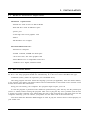
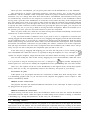
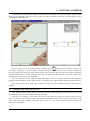
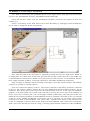
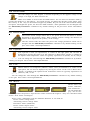
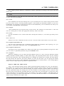
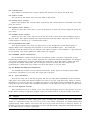
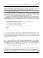
4.5 V battery from three 1.5 V pencil batteries connected in series
These batteries are similar to typical low voltage batteries.
The batteries have an internal resistance parameter which can be zero (default) or user-defined. You
can specify the internal resistance by using the Edit.Modify Parameters command or double-clicking
on the part. Error status: None/Run-down.
5.7
Power Supply
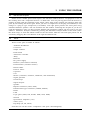
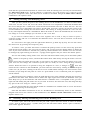
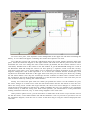
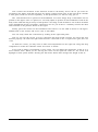
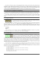
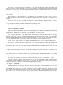
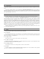
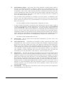
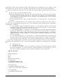
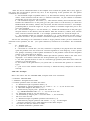
This part is like a typical lab variable DC power supply with a digital voltage
display.You can quickly make voltage adjustments with the front panel buttons.
To change the voltage in large steps (1 V as default), click on the left button.
Clicking on the left or on the right side of a button specifies whether the power
supply will decrease or increase its value. This is shown by the small + or – signs above the buttons. Hold
down the mouse button, and the voltage will continuously changing until you release it. To change the
voltage in small steps, click on the right button in the same way.
You can change the power supply voltage limits, increments, etc. through the Edit.Modify Parameters command or by double-clicking on the component on a neutral part of the shape. Error
status: None/Open.
5.8
Resistors
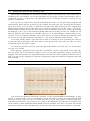
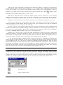
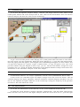
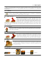
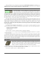
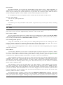
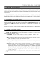
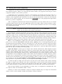
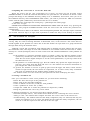
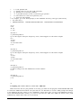
Edison offers two resistors, each operating the same way but differing in
appearance. The color-coded resistor indicates its actual value with standard color coding. The printed resistor has its resistance printed on it. Note that the Shift bar changes
the basic color of the color coded resistor.
You can change the resistance through the Edit.Modify Parameters command or by doubleclicking on the part. When you have set a new resistance value, the default resistance value will change
to this value. If you then pick up another resistor from the shelf, its value will be the new default value.
Error status: None/Open.
5.9
Potentiometer (Variable Resistor)
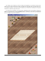
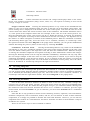
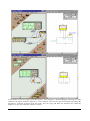
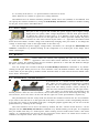
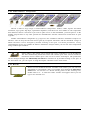
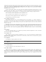
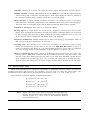
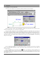
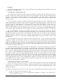
A potentiometer is a variable resistor with three terminals. There are two kinds of potentiometers available
in Edison. One is controlled by a slider, the other by a
rotary knob. The sliding contact (“slider”) linearly divides the total resistance between left and right connections. The slider can be dragged and dropped to the
desired position. There are also two buttons, one for decreasing and one for increasing the setting. To
activate these, move the cursor on the left and the right side of the potentiometer respectively.
The potentiometer with the rotary knob also divides the resistance between the two end terminals.
If you click on the left side or on the right side of the knob, it will turn it in the corresponding direction.
If you move the cursor to the middle of the part, a triangular graphic appears that you can use to set the
potentiometer by clicking on the triangle.
The total resistance end to end is 50 ohms by default, but this—and the actual division—can be
changed with the Edit.Modify Parameters command or by double-clicking on the part. It is important
that you double-click only at a neutral place, where clicking will not induce other actions. The actual
settings of a potentiometer can also be seen by moving the cursor above it if “Hints above circuits” is
enabled in the Options menu. Error status: None/Open.
23