1
Preface, Contents
Product Overview
1
Installation and Setup
Guidelines for the C7
2
Special Features of C7
3
Communication between the
CPU and the Operator Panel
4
Communication Functions
5
C7 Digital I/O
6
C7 Analog I/O
7
C7 Universal Inputs
8
Data Set Description, I/O
Parameter Assignment
9
SIMATIC
C7-633 / C7-634
Control Systems
Manual
This manual is part of the
documentation package with the
order number:
6ES7633-1AF01-8BA0
I/O Diagnostics
10
Maintenance
11
Appendices
10/98
C79000-G7076-C634
Release 01
System Messages
A
Technical Specifications
for the C7
B
Guidelines for Handling
Electrostatically-Sensitive
Devices (ESD)
C
Literature on SIMATIC S7
and C7
D
Glossary, Index
Safety Guidelines
!
#$. ()0' *)/$). )*/$ . 2#$# 4*0 .#*0' *. -1 /* ).0- 4*0- *2) + -.*)' .! /4 . 2 '' . /*
+-*/ / /# +-*0/ ) *)) / ,0$+( )/ # . )*/$ . - #$"#'$"#/ $) /# ()0' 4 2-)$)"
/-$)"' ) - (-& . !*''*2. *-$)" /* /# ' 1 ' *! )" -
Warning
$)$/ ./#/ /# . 1 - + -.*)' $)%0-4 *- .0./)/$' +-*+ -/4 (" ) - .0'/ $! +-*+ - +- 0/$*). )*/ /& )
Note
-2.4*0- // )/$*) /* +-/$0'-'4 $(+*-/)/ $)!*-(/$*) *) /# +-*0/ #)'$)" /# +-*0/ *- /* +-/$0'+-/ *! /# *0( )//$*)
Qualified Personnel
# 1$ .4./ ( (4 *)'4 . / 0+ ) *+ -/ $) *)%0)/$*) 2$/# /#$. ()0'
)'4 qualified personnel .#*0' ''*2 /* $)./'' ) 2*-& *) /#$. ,0$+( )/ 0'$!$ + -.*).
- !$) . + -.*). 2#* - 0/#*-$5 /* *(($..$*) /* "-*0) ) /* /" $-0$/. ,0$+( )/ )
.4./ (. $) *-) 2$/# ./'$.# .! /4 +-/$ . ) ./)-.
Correct Usage
!
*/ /# !*''*2$)"
Warning
#$. 1$ ) $/. *(+*) )/. (4 *)'4 0. !*- /# ++'$/$*). .-$ $) /# /'*" *- /# / #)$'
.-$+/$*) ) *)'4 $) *)) /$*) 2$/# 1$ . *- *(+*) )/. !-*( */# - ()0!/0- -. 2#$# #1 )
++-*1 *- - *(( ) 4 $ ( ).
#$. +-*0/ ) *)'4 !0)/$*) *-- /'4 ) .! '4 $! $/ $. /-).+*-/ ./*- . / 0+ ) $)./'' *-- /'4 )
*+ -/ ) ($)/$) . - *(( ) !
!
Trademarks
Caution
UL + CSA: Lithium Battery Replacement
)" - *! 3+'*.$*) $! // -4 $. $)*-- /'4 - +' +' *)'4 2$/# .( *- ,0$1' )/ /4+
- *(( ) 4 /# ()0!/0- - $.+*. *! 0. // -$ . *-$)" /* /# ()0!/0- -. $)./-0/$*).
Warning
FM WARNING 6
R ) R ) R - - "$./ - /- (-&. *! #$- +-/$ . 0.$)" !*- /# $- *2) +0-+*. . )4 */# - )( . $) /#$. *0( )/ 2#$# - ! - /* /- (-&. ($"#/
$)!-$)" 0+*) /# -$"#/. *! /# /- (-& *2) -.
Copyright E Siemens AG 1998 All rights reserved
Disclaimer of Liability
The reproduction, transmission or use of this document or its
contents is not permitted without express written authority.
Offenders will be liable for damages. All rights, including rights
created by patent grant or registration of a utility model or design, are
reserved.
We have checked the contents of this manual for agreement with the
hardware and software described. Since deviations cannot be
precluded entirely, we cannot guarantee full agreement. However,
the data in this manual are reviewed regularly and any necessary
corrections included in subsequent editions. Suggestions for
improvement are welcomed.
$ ( ). Bereich Automatisierungs- und Antriebstechnik
Geschaeftsgebiet Industrie-Automatisierungssysteme
Postfach 4848, D-90327 Nuernberg
Siemens Aktiengesellschaft
E Siemens AG 1998
0% / /* #)" 2$/#*0/ +-$*- )*/$ C79000–G7076–C634
C7-633/C7-634 Control Systems
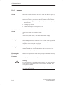
Preface
Purpose of the
Manual
This manual provides you with a complete overview of the C7-633 P,
C7-633 DP, C7-634 P and C7-634 DP control systems. It offers support for
the installation and commissioning of these systems, outlines the possibilities
for connecting other devices, and introduces the components required for
this.
Where is this
Manual Valid?
This manual is valid for the following device variants:
Audience and
Requirements
C7
Order Number
C7-633 P
6ES7633-1DF00-0AE3
C7-633 DP
6ES7633-2BF00-0AE3
C7-634 P
6ES7634-2DBF00-0AE3
C7-634 DP
6ES7634-2BF00-0AE3
This manual is intended for personnel with the necessary qualifications for
commissioning, operating, and programming the hardware product described.
You should be familiar with the use of computers or devices with similar
functions to a PC (for example, programming devices) under the operating
system Windows 95 / NT 4.0 and have some knowledge of the STEP 7
Standard software and the ProTool configuration software and the relevant
documentation.
C7 Documentation
Package
The control systems comprise the following individual components:
S SIMATIC S7-300
S SIMATIC Operator Panel
You will find information on these individual components in the version of
the C7 documentation package valid for your control systems. This
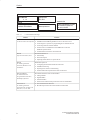
documentation package comprises four manuals and an instruction list. You
will find the contents listed in Table 1-1:
C7-633/C7-634 Control Systems
C79000-G7076-C634-01
iii
Preface
%
%
!"$ " %
" %
' " " $" "
"&" #$$ % !$ #
Table 1-1
#$"%$ #$
' " " $" "
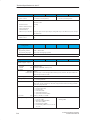
' C7 Documentation Package
Manual
Contents
Manual
Provides information on the topics:
C7-633/C7-634 Control Systems S Installation and installation guidelines for the C7-633 and C7-634
S Connecting the C7 systems to a programming device and other devices
S Connecting an IM 361 interface module
S Features of the C7 and differences from SIMATIC S7-300 and
SIMATIC Operator Panels
S Communication between the CPU and the OP
Manual
Operator Panel OP7, OP17
Provides information on:
Manual
S7-300 Programmable
Controller, Hardware and
Installation
Detailed description of:
Reference Manual:
S7-300 and M7-300
Programmable Controllers,
Module Specifications
Instruction List
S7-300 Programmable
Controller CPU 312 IFM, 314
IFM, 313, 314, 315-2DP
iv
S Functionality
S Device description
S Operating modes and how to operate the OP
S
S
S
S
Configuring the mechanical and electrical structure
Installation and wiring
Preparing the S7-300 for commissioning
Features and technical specifications of the S7-300 CPUs
Describes the hardware of the S7-300 modules:
S
S
S
S
S
S
Analog modules
Digital modules
Interface modules
Characteristics and technical specifications of the S7-300 modules
List of instructions for the CPUs
Brief description of the instructions and the execution times
C7-633/C7-634 Control Systems
C79000-G7076-C634-01
Preface
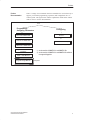
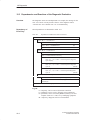
Further
Documentation
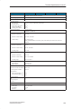
There is a range of user manuals which are intended to be used selectively to
support you with the programming, expansion, and configuration of a C7
control system. The figure below and the explanations which follow should
make it easier to use the documentation.
C7
Programming
Assigning Parameters
Configuring
ProTool *)
STL for S7-300/S7-400
or
LAD for S7-300/S7-400
ProTool/Lite **)
FBD for S7-300/S7-400
System and Standard
Functions
STEP 7 User Manual
Program Design Manual
C7-633/C7-634 Control Systems
C79000-G7076-C634-01
If required
v
Preface
Table 1-2
STEP 7 Documentation Package, Order Number, see Catalog ST 70
Manual
User Manual:
Standard Software for S7 and
M7
Contents
Provides information on working with the STEP 7 applications:
S Installing and starting up STEP 7 on a PC/programming device
S Handling the applications with the following contents:
–
Managing projects and files
–
Configuring and assigning parameters to the S7-300
–
Assigning symbolic names for user programs
–
Creating and debugging the user program in STL/LAD
–
Creating data blocks
S Configuring communications between several CPUs:
–
Downloading/uploading, storing, and deleting the user program
–
Monitoring and modifying the user program (for example, variables)
–
Monitoring and modifying the CPU (for example, operating state, memory
reset, compressing memory, protection levels)
Manual: Statement List (STL) for Reference manuals for programming with STL, LAD, or FBD:
S7-300/400,
S Basics of working with STL/LAD/FBD
Programming
(for example, structure of STL/LAD/FBD, number formats, syntax)
or
S Description of all instructions in STEP 7
Manual: Ladder Logic (LAD)
for S7-300/400,
Programming
or
Manual: Function Block
Diagram (FBD) for S7-300/400,
Programming
(with sample programs)
S Description of the various methods of addressing in STEP 7
(with examples)
S Description of all integrated functions of the CPUs
S Description of the CPU-internal registers
Reference Manual
Detailed description of:
System Software for S7-300/400, S All organization blocks (OB) and their priority classes
System and Standard Functions
S All standard functions (FC) integrated in STEP 7
S All system functions (SFC) integrated in the operating system of a CPU
Programming Manual
Teaches the basic requirements for creating STEP 7 programs:
System Software for S7-300/400, S Guide to the efficient solution of the programming task using a
Program Design
PC/programming device and STEP 7
S How the CPUs work (for example, memory concept, access to inputs/outputs,
addressing, blocks, data types, data management)
S
S
S
S
S
Description of STEP 7 data management
Using the STEP 7 data types
Using linear and structured programming (with program samples)
Using block call instructions
Overview of using the STEP 7 applications for developing projects (with
detailed example)
S Using test and diagnostics functions of the CPUs in the user program
(for example, error OBs, status word)
vi
C7-633/C7-634 Control Systems
C79000-G7076-C634-01
Preface
Table 1-3
Other Manuals that Provide Helpful Information on How to Operate the C7 Control System
Contents
Manual
PG 7xx
Describes the programming device (PG) hardware:
S
S
S
S
ProTool / ProTool/Lite
Setting up and starting up the programming device
Expansion possibilities
Configuration
Error diagnostics
Manual for creating configurations with ProTool or ProTool/Lite:
S
S
S
S
Manual:
Communication with SIMATIC
Using ProTool/ProTool/Lite
Configuring
Displays and messages
Loading the configuration into the C7
Describes communication in the SIMATIC S7/M7/C7:
S
S
S
S
Introduction to the theory of communications
Communication utilities
Structure and configuration of communication networks
Examples of the various communication possibilities
Conventions
To make it easier to read this manual, we have used C7 throughout the
manual to stand for the device types C7-633 P, C7-633 DP, C7-634 P, and
C7-634 DP.
Other Sources of
Information
In the literature list at the end of the manual you will find a list of other
sources of information on S7-300 and programmable logic controllers.
Structure of This
Manual
To make it easier for you to locate specific information, the manual has been
structured as follows:
S At the beginning of the manual, you will find a complete table of contents
for the manual.
S In the individual chapters, the information in the left margin gives an
overview of the contents of each section.
S Following the appendices, there is a glossary containing definitions of the
important technical terms used in the manual.
S At the end of the manual, you will find a detailed index giving you fast
access to the information you seek.
Standards
The C7 control system conforms to the standards listed in Appendix B.1.
C7-633/C7-634 Control Systems
C79000-G7076-C634-01
vii
Preface
Further Support
If you have any questions about using the C7 control systems described in
this manual and cannot find an answer here, please contact the Siemens
representative in your area. You can obtain a list of addresses of Siemens
representatives worldwide from the SIMATIC Customer Support Hotline.
If you have any questions or comments on this manual, please fill out the
remarks form at the end of the manual and return it to the address shown on
the form. We would be grateful if you could also take the time to answer the
questions giving your personal opinion of the manual.
viii
C7-633/C7-634 Control Systems
C79000-G7076-C634-01
Preface
SIMATIC Customer
Support Hotline
Open round the clock, world-wide:
Nuremberg
Johnson City
Singapore
SIMATIC Basic Hotline
Nuremberg
Johnson City
Singapore
SIMATIC BASIC Hotline
SIMATIC BASIC Hotline
SIMATIC BASIC Hotline
Local time:
Phone:
Fax:
E-Mail:
Local time:
Phone:
Fax:
E-Mail:
Local time:
Phone:
Fax:
E-Mail:
GMT:
GMT:
GMT:
Mo.-Fr. 7:00 to 19:00
+49 (911) 895-7000
+49 (911) 895-7002
simatic.support@
nbgm.siemens.de
+1:00
Mo.-Fr. 8:00 to 17:00
+1 423 461-2522
+1 423 461-2231
simatic.hotline@
sea.siemens.com
-5:00
Mo.-Fr. 8:30 to 17:30
+65 740-7000
+65 740-7001
simatic@
singnet.com.sg
+8:00
SIMATIC Premium Hotline
(Calls charged, only with
SIMATIC Card)
Time:
Mo.-Fr. 0:00 to 24:00
Phone:
+49 (911) 895-7777
Fax:
+49 (911) 895-7001
GMT:
+01:00
SIMATIC Customer
Support Online
Services
The SIMATIC Customer Support team provides you with comprehensive
additional information on SIMATIC products via its online services:
S You can obtain general current information:
– On the Internet under
http://www.ad.siemens.de/simatic/html_00/simatic
.htm
– Using fax polling no. 08765-93 02 77 95 00
S Current Product Information leaflets and downloads which you may find
useful for your product are available:
– On the Internet under
http://www.ad.siemens.de/support/html-00/
– Via the Bulletin Board System (BBS) in Nuremberg (SIMATIC
Customer Support Mailbox) under the number +49 (911) 895-7100.
To access the mailbox, use a modem with V.34 (28.8 Kbps) capability
whose parameters you should set as follows: 8, N, 1, ANSI, or dial in
using ISDN (x.75, 64 Kbps).
C7-633/C7-634 Control Systems
C79000-G7076-C634-01
ix
Preface
x
C7-633/C7-634 Control Systems
C79000-G7076-C634-01
Contents
1
2
3
4
Preface . . . . . . . . . . . . . . . . . . . . . . . . . . . . . . . . . . . . . . . . . . . . . . . . . . . . . . . . . . . . . . . .
iii
Product Overview . . . . . . . . . . . . . . . . . . . . . . . . . . . . . . . . . . . . . . . . . . . . . . . . . . . . . .
1-1
1.1
Product Variants . . . . . . . . . . . . . . . . . . . . . . . . . . . . . . . . . . . . . . . . . . . . . . . .
1-2
1.2
Scope of Supply and Accessories for C7 . . . . . . . . . . . . . . . . . . . . . . . . . . .
1-5
1.3
Components for Connection to a C7 . . . . . . . . . . . . . . . . . . . . . . . . . . . . . . .
1-6
Installation and Setup Guidelines for the C7 . . . . . . . . . . . . . . . . . . . . . . . . . . . . . .
2-1
2.1
Labeling Strips . . . . . . . . . . . . . . . . . . . . . . . . . . . . . . . . . . . . . . . . . . . . . . . . . .
2-2
2.2
Mechanical Installation . . . . . . . . . . . . . . . . . . . . . . . . . . . . . . . . . . . . . . . . . . .
2-5
2.3
Electrical Installation . . . . . . . . . . . . . . . . . . . . . . . . . . . . . . . . . . . . . . . . . . . . .
2-9
2.4
Connector Assignments . . . . . . . . . . . . . . . . . . . . . . . . . . . . . . . . . . . . . . . . . .
2-13
2.5
Connecting a Programming Device/PC to a C7 . . . . . . . . . . . . . . . . . . . . . .
2-17
2.6
Connecting a Programming Device/PC to Several Nodes . . . . . . . . . . . . .
2-18
2.7
Setup Guidelines for Interference-Free Installation . . . . . . . . . . . . . . . . . . .
2-20
2.8
Connecting Shielded Cables . . . . . . . . . . . . . . . . . . . . . . . . . . . . . . . . . . . . . .
2-22
2.9
Encoding Connectors . . . . . . . . . . . . . . . . . . . . . . . . . . . . . . . . . . . . . . . . . . . .
2-23
2.10
Expanding the C7 with S7-300 Modules . . . . . . . . . . . . . . . . . . . . . . . . . . . .
2-24
2.11
Configuring an MPI and PROFIBUS DP Network . . . . . . . . . . . . . . . . . . . .
2-26
Special Features of C7 . . . . . . . . . . . . . . . . . . . . . . . . . . . . . . . . . . . . . . . . . . . . . . . . . .
3-1
3.1
Variations from the Individual Components CPU and OP . . . . . . . . . . . . . .
3-2
3.2
Selecting a C7 CPU Operating Mode . . . . . . . . . . . . . . . . . . . . . . . . . . . . . .
3-4
3.3
DI/DO Status Displays . . . . . . . . . . . . . . . . . . . . . . . . . . . . . . . . . . . . . . . . . . .
3-6
3.4
Status and Error Indicators on the C7 CPU . . . . . . . . . . . . . . . . . . . . . . . . .
3-7
Communication between the CPU and the Operator Panel . . . . . . . . . . . . . . . . .
4-1
4.1
Configured Communications Parameters . . . . . . . . . . . . . . . . . . . . . . . . . . .
4-2
4.2
Overview of User Data Areas . . . . . . . . . . . . . . . . . . . . . . . . . . . . . . . . . . . . .
4-3
4.3
Event and Alarm Messages . . . . . . . . . . . . . . . . . . . . . . . . . . . . . . . . . . . . . . .
4-4
4.4
4.4.1
4.4.2
4.4.3
Keyboard and LED Image . . . . . . . . . . . . . . . . . . . . . . . . . . . . . . . . . . . . . . . .
System Keyboard Image . . . . . . . . . . . . . . . . . . . . . . . . . . . . . . . . . . . . . . . . .
Function Keyboard Image . . . . . . . . . . . . . . . . . . . . . . . . . . . . . . . . . . . . . . . .
LED Image . . . . . . . . . . . . . . . . . . . . . . . . . . . . . . . . . . . . . . . . . . . . . . . . . . . . .
4-8
4-9
4-10
4-11
C7-633/C7-634 Control Systems
C79000-G7076-C634-01
xi
Contents
5
6
7
4.5
Screen Number Area . . . . . . . . . . . . . . . . . . . . . . . . . . . . . . . . . . . . . . . . . . . .
4-12
4.6
User Version . . . . . . . . . . . . . . . . . . . . . . . . . . . . . . . . . . . . . . . . . . . . . . . . . . . .
4-13
4.7
4.7.1
4.7.2
Interface Area . . . . . . . . . . . . . . . . . . . . . . . . . . . . . . . . . . . . . . . . . . . . . . . . . .
Control and Checkback Bits . . . . . . . . . . . . . . . . . . . . . . . . . . . . . . . . . . . . . .
Data Areas in the Interface Area . . . . . . . . . . . . . . . . . . . . . . . . . . . . . . . . . .
4-14
4-15
4-17
4.8
4.8.1
4.8.2
4-19
4-20
4.8.3
4.8.4
Recipes . . . . . . . . . . . . . . . . . . . . . . . . . . . . . . . . . . . . . . . . . . . . . . . . . . . . . . . .
Transferring Data Records . . . . . . . . . . . . . . . . . . . . . . . . . . . . . . . . . . . . . . . .
Addressing Recipes and Data Records, and the Requisite
Data Areas . . . . . . . . . . . . . . . . . . . . . . . . . . . . . . . . . . . . . . . . . . . . . . . . . . . . .
Synchronization during Transfer - Normal Case . . . . . . . . . . . . . . . . . . . . . .
Synchronization during Transfer - Special Cases . . . . . . . . . . . . . . . . . . . .
4.9
Notes on Optimization . . . . . . . . . . . . . . . . . . . . . . . . . . . . . . . . . . . . . . . . . . .
4-23
4.10
4.10.1
Control Jobs and Their Parameters . . . . . . . . . . . . . . . . . . . . . . . . . . . . . . . .
Example of How to Activate a Control Job . . . . . . . . . . . . . . . . . . . . . . . . . .
4-24
4-31
Communication Functions . . . . . . . . . . . . . . . . . . . . . . . . . . . . . . . . . . . . . . . . . . . . . .
5-1
5.1
Introduction . . . . . . . . . . . . . . . . . . . . . . . . . . . . . . . . . . . . . . . . . . . . . . . . . . . . .
5-2
5.2
Communication between C7/S7 Stations (MPI Subnet) . . . . . . . . . . . . . . .
5-3
5.3
Communication within a C7 Station (PROFIBUS DP or IM) . . . . . . . . . . .
5-5
C7 Digital I/O . . . . . . . . . . . . . . . . . . . . . . . . . . . . . . . . . . . . . . . . . . . . . . . . . . . . . . . . . . .
6-1
6.1
Digital Inputs . . . . . . . . . . . . . . . . . . . . . . . . . . . . . . . . . . . . . . . . . . . . . . . . . . .
6-2
6.2
Digital Outputs . . . . . . . . . . . . . . . . . . . . . . . . . . . . . . . . . . . . . . . . . . . . . . . . . .
6-5
6.3
DI/DO Status Displays . . . . . . . . . . . . . . . . . . . . . . . . . . . . . . . . . . . . . . . . . . .
6-8
6.4
Addressing the C7 I/O . . . . . . . . . . . . . . . . . . . . . . . . . . . . . . . . . . . . . . . . . . .
6-9
C7 Analog I/O . . . . . . . . . . . . . . . . . . . . . . . . . . . . . . . . . . . . . . . . . . . . . . . . . . . . . . . . . .
7-1
7.1
Analog Technology . . . . . . . . . . . . . . . . . . . . . . . . . . . . . . . . . . . . . . . . . . . . . .
7-2
7.2
7.2.1
Connecting Transducers to Analog Inputs . . . . . . . . . . . . . . . . . . . . . . . . . .
Connecting Voltage and Current Transducers . . . . . . . . . . . . . . . . . . . . . . .
7-3
7-6
7.3
Connecting Loads/Actuators to the Analog Output . . . . . . . . . . . . . . . . . . .
7-7
7.4
7.4.1
Analog Input Function . . . . . . . . . . . . . . . . . . . . . . . . . . . . . . . . . . . . . . . . . . . .
Characteristics and Technical Specifications of the Analog Input Module
7-10
7-11
7.5
Analog Output Function . . . . . . . . . . . . . . . . . . . . . . . . . . . . . . . . . . . . . . . . . .
7-15
7.6
7.6.1
7.6.2
7.6.3
7.6.4
7.6.5
Use and Function of the C7 Analog I/O . . . . . . . . . . . . . . . . . . . . . . . . . . . . .
Addressing the Analog I/O . . . . . . . . . . . . . . . . . . . . . . . . . . . . . . . . . . . . . . . .
Timing of the Analog I/Os . . . . . . . . . . . . . . . . . . . . . . . . . . . . . . . . . . . . . . . . .
Assigning Parameters to the Analog I/O . . . . . . . . . . . . . . . . . . . . . . . . . . . .
Representation of Analog Values . . . . . . . . . . . . . . . . . . . . . . . . . . . . . . . . . .
Representation of Analog Values for the Measurement Ranges
of the Analog Inputs . . . . . . . . . . . . . . . . . . . . . . . . . . . . . . . . . . . . . . . . . . . . .
Representation of Analog Values for the Output Range
of the Analog Outputs . . . . . . . . . . . . . . . . . . . . . . . . . . . . . . . . . . . . . . . . . . . .
Conversion and Cycle Time of the Analog Inputs . . . . . . . . . . . . . . . . . . . .
Conversion, Cycle, Settling and Response Times of Analog Outputs . . .
7-18
7-18
7-19
7-21
7-27
7.6.6
7.6.7
7.6.8
xii
4-20
4-21
4-22
7-28
7-30
7-31
7-32
C7-633/C7-634 Control Systems
C79000-G7076-C634-01
Contents
8
9
7.6.9
7.6.10
Behavior of the Analog I/O . . . . . . . . . . . . . . . . . . . . . . . . . . . . . . . . . . . . . . . .
Time Interrupt/Interrupt Cycle . . . . . . . . . . . . . . . . . . . . . . . . . . . . . . . . . . . . .
7-33
7-35
7.7
7.7.1
7.7.2
Examples for Programming the Analog I/O . . . . . . . . . . . . . . . . . . . . . . . . . .
Block for Scaling Analog Input Values . . . . . . . . . . . . . . . . . . . . . . . . . . . . . .
Block for Scaling Analog Output Values . . . . . . . . . . . . . . . . . . . . . . . . . . . .
7-36
7-36
7-39
C7 Universal Inputs . . . . . . . . . . . . . . . . . . . . . . . . . . . . . . . . . . . . . . . . . . . . . . . . . . . . .
8-1
8.1
Universal Inputs . . . . . . . . . . . . . . . . . . . . . . . . . . . . . . . . . . . . . . . . . . . . . . . . .
8-2
8.2
8.2.1
8.2.2
8.2.3
8.2.4
8.2.5
8.2.6
8.2.7
Use and Function of the Universal Inputs . . . . . . . . . . . . . . . . . . . . . . . . . . .
Addressing Universal Inputs . . . . . . . . . . . . . . . . . . . . . . . . . . . . . . . . . . . . . .
Assigning Parameters to the Universal Inputs . . . . . . . . . . . . . . . . . . . . . . .
Interrupt Inputs and Counter Interrupts . . . . . . . . . . . . . . . . . . . . . . . . . . . . .
Counters . . . . . . . . . . . . . . . . . . . . . . . . . . . . . . . . . . . . . . . . . . . . . . . . . . . . . . .
Frequency Counters . . . . . . . . . . . . . . . . . . . . . . . . . . . . . . . . . . . . . . . . . . . . .
Period Time Measurement . . . . . . . . . . . . . . . . . . . . . . . . . . . . . . . . . . . . . . . .
External Gate Counter . . . . . . . . . . . . . . . . . . . . . . . . . . . . . . . . . . . . . . . . . . .
8-6
8-6
8-9
8-12
8-14
8-17
8-19
8-22
8.3
Example for Programming the Counters . . . . . . . . . . . . . . . . . . . . . . . . . . . .
8-23
Data Set Description, I/O Parameter Assignment . . . . . . . . . . . . . . . . . . . . . . . . . .
9-1
9.1
10
11
Data Set Description for Parameter Block of C7 Analog I/O
and Universal Inputs . . . . . . . . . . . . . . . . . . . . . . . . . . . . . . . . . . . . . . . . . . . . .
9-2
I/O Diagnostics . . . . . . . . . . . . . . . . . . . . . . . . . . . . . . . . . . . . . . . . . . . . . . . . . . . . . . . .
10-1
10.1
Diagnostic Messages . . . . . . . . . . . . . . . . . . . . . . . . . . . . . . . . . . . . . . . . . . . .
10-2
10.2
Diagnostic Data of the C7 Analog I/O and Universal Inputs . . . . . . . . . . . .
10-4
10.3
Dependencies and Reactions of the Diagnostic Evaluation . . . . . . . . . . . .
10-8
Maintenance . . . . . . . . . . . . . . . . . . . . . . . . . . . . . . . . . . . . . . . . . . . . . . . . . . . . . . . . . . .
11-1
11.1
Changing the Backup Battery . . . . . . . . . . . . . . . . . . . . . . . . . . . . . . . . . . . . .
11-2
11.2
Replacing the C7 . . . . . . . . . . . . . . . . . . . . . . . . . . . . . . . . . . . . . . . . . . . . . . . .
11-4
A
System Messages . . . . . . . . . . . . . . . . . . . . . . . . . . . . . . . . . . . . . . . . . . . . . . . . . . . . . .
A-1
B
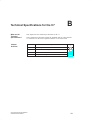
Technical Specifications for the C7 . . . . . . . . . . . . . . . . . . . . . . . . . . . . . . . . . . . . . .
B-1
B.1
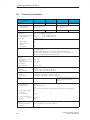
Technical Specifications . . . . . . . . . . . . . . . . . . . . . . . . . . . . . . . . . . . . . . . . . .
B-2
B.2
Notes on the CE Marking . . . . . . . . . . . . . . . . . . . . . . . . . . . . . . . . . . . . . . . . .
B-11
B.3
Notes for Machine Manufacturers . . . . . . . . . . . . . . . . . . . . . . . . . . . . . . . . . .
B-12
B.4
Transport and Storage Conditions for Backup Batteries . . . . . . . . . . . . . . .
B-13
Guidelines for Handling Electrostatically-Sensitive Devices (ESD) . . . . . . . . .
C-1
C.1
What is ESD? . . . . . . . . . . . . . . . . . . . . . . . . . . . . . . . . . . . . . . . . . . . . . . . . . . .
C-2
C.2
Electrostatic Charging of Objects and Persons . . . . . . . . . . . . . . . . . . . . . .
C-3
C.3
General Protective Measures against Electrostatic Discharge Damage .
C-4
C.4
Taking Measurements and Working on ESD Modules . . . . . . . . . . . . . . . .
C-6
C.5
Packing Electrostatically-Sensitive Devices . . . . . . . . . . . . . . . . . . . . . . . . .
C-6
C
C7-633/C7-634 Control Systems
C79000-G7076-C634-01
xiii
Contents
D
Literature on SIMATIC C7 and S7 . . . . . . . . . . . . . . . . . . . . . . . . . . . . . . . . . . . . . . . .
D-1
Glossary . . . . . . . . . . . . . . . . . . . . . . . . . . . . . . . . . . . . . . . . . . . . . . . . . . . . . . . . . . Glossary-1
Index . . . . . . . . . . . . . . . . . . . . . . . . . . . . . . . . . . . . . . . . . . . . . . . . . . . . . . . . . . . . .
xiv
Index-1
C7-633/C7-634 Control Systems
C79000-G7076-C634-01
Product Overview
In This Chapter...
1
This chapter introduces the different variants of the device. A brief overview
of the scope of functions of the device helps to give you a first impression of
the C7 control systems.
In addition, this chapter also explains which other components you can
connect to a C7 control system.
Accessories for
Operating a C7
Control System
To operate a C7 control system you will require the following accessories:
S Programming device (PG) or PC with multipoint interface (MPI),
S An MPI cable
S A serial cable (RS 232/TTY),
S A 24-V power supply
S The following programs must be loaded on the programming device or
PC:
– The STEP 7 or STEP 7-Mini applications
– The configuration tool ProTool or ProTool/Lite
C7-633/C7-634 Control Systems
C79000-G7076-C634-01
1-1
Product Overview
1.1
Product Variants
Overview
The C7 devices are available in the following variants:
S C7-633 P, C7-633 DP
S C7-634 P, C7-634-DP
C7-633 P/
C7-633 DP
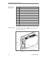
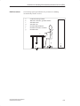
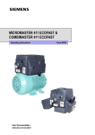
The C7-633 and C7-633 DP control systems have a SIMATIC S7-300
CPU 315 or CPU 315-2 DP as the C7 CPU and an OP 7 with extended
function keys as the C7 OP (see Section 3.1).
The screen display comprises four lines of 20 characters with a character
height of 8 mm.
The C7-633 P is fitted with an integrated I/O module and has no DP
interface.
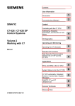
Figure 1-1
C7-633 P
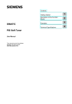
The C7-633 DP does not have an integrated on-board I/O.
Figure 1-2
1-2
C7-633 DP
C7-633/C7-634 Control Systems
C79000-G7076-C634-01
Product Overview
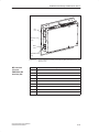
C7-634 P/
C7-634 DP
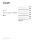
The C7-634 P and C7-634 DP control systems have a SIMATIC S7-300
CPU 315 or CPU 315-2 DP as the C7 CPU and an OP 17 as the C7 OP.
The screen display can be configured as follows:
S Four lines of 20 characters with 11 mm character height or
S Eight lines of 40 characters with 6 mm character height.
The different character heights can also be combined with the basic
configuration of 8*40 in a display.
The C7-634 P is fitted with an integrated I/O module and has no DP
interface.
Figure 1-3
C7-634 P
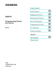
The C7-634 DP has no integrated on-board I/O.
Figure 1-4
C7-633/C7-634 Control Systems
C79000-G7076-C634-01
C7-634 DP
1-3
Product Overview
PROFIBUS DP Bus
Connection
The C7-633 DP and C7-634 DP control systems can be connected via the
integrated DP interface to a PROFIBUS DP network.
Scope of
Functions
With the C7 devices you can:
S Download user programs to the C7 CPU and run them.
S Communicate with other nodes in an MPI or PROFIBUS DP network via
an integrated MPI or DP interface.
S Process digital and analog signals using the C7’s integral I/O.
S Use interrupt inputs or counters (for purposes including frequency
metering, period duration measurement).
S Load and execute operator interface configurations you created with the
configuration tools “ProTool” or “ProTool/Lite.”
S Using these configurations you can monitor and influence the process
which you control with the user program.
S Connect other S7 modules via the IM 361 interface module.
S Output data to a connected printer.
C7 Components
The C7 contains two units that work independently of each other and
communicate via an internal multipoint interface:
S C7 CPU:
controls
S C7 Operator Panel: operates and monitors
The C7 CPU is independent of the C7 OP. The C7 OP continues to run, for
example, when the C7 CPU goes into STOP.
Note
The C7 CPU and the C7 OP each have an MPI address. You therefore
configure these components exactly the same as the stand-alone components
CPU and OP.
These components are discussed explicitly in the manual as necessary.
1-4
C7-633/C7-634 Control Systems
C79000-G7076-C634-01
Product Overview
1.2
Scope of Supply and Accessories for C7
Parts Supplied
The following components are included in the scope of supply of a C7
device:
S C7-633 P, C7-633 DP, C7-634 P, or C7-634 DP
S Battery (integrated in the device)
S One grounding bar (C7-633 P and C7-634 P only)
S Six shielding clips (C7-633 P and C7-634 P only)
S Seal and four screw-in tensioners
S Power supply connector (4-pin)
S Product Information (as required)
S Connector set (C7-633 P and C7-634 P only)
Accessories
The following components can be ordered as important C7 standard
accessories:
Component
Identifying Data
PG cable (MPI)
(connects C7 to PG)
Order Number
See catalog ST 70
PG cable (TTY)
(serial transfer (ProTool))
PC/MPI cable
5m
Printer cable
for RS 232 serial interface
(max. 16 m)
Spare Parts
The following components can be ordered as spare parts for the C7:
Component
Service package
Identifying Data
Seal and 4 screw-in
tensioners
Order Number
See catalog ST 70
Backup battery
Connector set for C7 I/Os
with solid and profiled
coding keys
C7-633/C7-634 Control Systems
C79000-G7076-C634-01
1-5
Product Overview
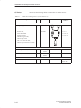
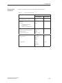
1.3
Components for Connection to a C7
In addition to the connections to the process, you can also connect different
components to the C7. The most important components and their functions
are listed in Table 1-1:
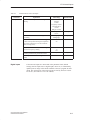
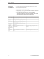
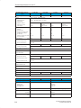
Table 1-1
Connectable Components of a C7
Component
Function
Interface module (IM 361)
... connects a C7 to an expansion
rack for S7-300 modules via an
IM 361 connecting cable
Signal modules (SM)
(digital input modules,
digital output modules,
analog input modules,
analog output modules,
analog I/O modules)
... adapt different process signal
levels to the C7 CPU. They can be
connected to the C7 via an IM 361
Function modules (FM)
... for time-critical and
memory-intensive process signal
processing tasks, for example,
positioning or closed-loop control
Communications processors (CP)
... relieves the CPU of
communication tasks, for example,
CP 342-5 DP for supporting FMS
services, point-to-point connections,
S5 connections, etc.
S7-300 (CPU)
... communicates via the MPI/DP
interface with the C7 and/or other
nodes in an MPI network
S7-400 (CPU)
... communicates via the MPI/DP
interface with the C7 and/or other
nodes in an MPI/DP network
1-6
Illustration
C7-633/C7-634 Control Systems
C79000-G7076-C634-01
Product Overview
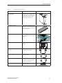
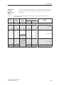
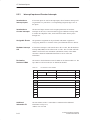
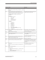
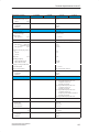
Table 1-1
Connectable Components of a C7
Component
Function
C7 I/O module
(expansion I/Os)
... is used for expanding the
integrated I/Os by 16 digital inputs,
16 digital outputs, 4 analog inputs, 4
analog outputs, and 4 universal
inputs directly on the device
C7 simulator modules
... with switches and LEDs to allow
simulation of 16 digital inputs and 16
digital outputs. It can be connected to
the C7 via an IM 361
Illustration
LEDs
SIMATIC TOP Connect
... permits easy, fast, and reliable
wiring of the I/O and power supply
connectors
OP (operator panel)
... executes operator interface
functions
PROFIBUS bus cable with bus
connector
... connects nodes of an MPI network
or L2-DP network together
Programming device cable (MPI)
... connects a programming
device/PC to a C7
Programming device cable (serial)
... connects a programming
device/PC to a C7 (RS 232/TTY).
Serial transfer with ProTool
Printer
... prints out operator interface
messages for the C7
C7-633/C7-634 Control Systems
C79000-G7076-C634-01
1-7
Product Overview
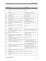
Table 1-1
Connectable Components of a C7
Component
Function
Programming device (PG) or PC
with the STEP 7 and ProTool
software packages
... configures, assigns parameters,
programs, and tests the C7
RS 485 repeater
... for amplifying the signals in an
MPI network or L2-DP network, and
for linking segments of an MPI or
L2-DP network
1-8
Illustration
C7-633/C7-634 Control Systems
C79000-G7076-C634-01
Product Overview
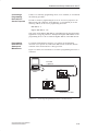
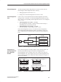
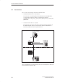
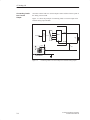
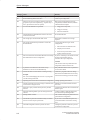
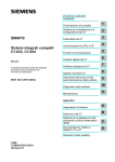
Example
Figure 1-5 shows some possible connections to other devices.
S7-300 CPU
S7-300 modules
IM 361
OP 25
C7
À
PG
Á
Â
Ã
Printer
Figure 1-5
ET 200 M with,
e.g. FM 355
À
Á
Â
Ã
RS 232 (V.24)/TTY
IM 361
MPI
PROFIBUS DP connection
Some C7 Connection Possibilities
C7-633/C7-634 Control Systems
C79000-G7076-C634-01
1-9
Product Overview
1-10
C7-633/C7-634 Control Systems
C79000-G7076-C634-01
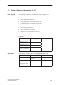
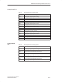
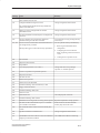
Installation and Setup Guidelines
for the C7
Chapter
Overview
C7-633/C7-634 Control Systems
C79000-G7076-C634-01
Section
Description
2
Page
2.1
Labeling Strips
2-2
2.2
Mechanical Installation
2-5
2.3
ElectricalInstallation
2-9
2.4
Connector Assignments
2-13
2.5
Connecting a Programming Device/PC to a C7
2-17
2.6
Connecting a Programming Device/PC to Several Nodes
2-18
2.7
Setup Guidelines for Interference-Free Installation
2-20
2.8
Connecting Shielded Cables
2-22
2.9
Encoding Connectors
2-23
2.10
Expanding the C7 with S7-300 Modules
2-24
2.11
Configuring an MPI and PROFIBUS DP Network
2-26
2-1
Installation and Setup Guidelines for the C7
2.1
Labeling Strips
Plant-Specific
Labeling
The function keys are labeled using labeling strips which are inserted into the
keypad from the side. When shipped, the function keys are labeled as
follows:
S C7-633: F1 to F4, K1 to K8, and K9 to K16.
S C7-634: F1 to F8, K1 to K8, and K9 to K16.
By exchanging the labeling strips, you can label the function keys of your C7
specifically for your plant.
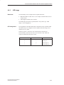
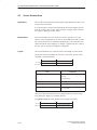
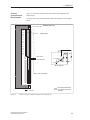
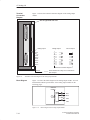
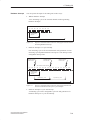
Making Labeling
Strips
To make your own labeling strips, use transparent foil so that the LEDs in the
function keys remain visible. Label the foil using either a printer or an
indelible pen so it cannot be erased. Cut the strips out using the templates
shown in Figures 2-1 (C7-633) and 2-2 (C7-634).
Note
Laser printouts are not indelible. You should therefore protect the printed
sheet with transparent adhesive foil.
Shipped with the ProTool configuration software are the WordR files
SLIDE633.DOC and SLIDE634.DOC. The files contain formatted
templates for labeling the function keys of C7-633 and C7-634 and can also
be used to edit and print your own individual labeling strips with a minimum
of effort. You will find the SLIDE63x.DOC and SLIDE634.DOC files in
the ProTool directory “Utility.”
2-2
C7-633/C7-634 Control Systems
C79000-G7076-C634-01
Installation and Setup Guidelines for the C7
Transparent LED window
Figure 2-1
Key surface can be labeled
Dimensions of the Labeling Strips for the C7-633
Transparent LED window
Figure 2-2
Key surface can be labeled
Dimensions of the Labeling Strips for the C7-634
C7-633/C7-634 Control Systems
C79000-G7076-C634-01
2-3
Installation and Setup Guidelines for the C7
Changing Labeling
Strips
The C7 is designed for user-friendly insertion of the labeling strips. The
labeling strips should only be changed when the C7 is not installed. Proceed
as follows to change the strips:
1. Pull the labeling strips you want to replace out of the device.
2. From the rear of the device, push the new strips into the relevant slots on
the side.
Note
The labels on the strips must be indelible before the strips are inserted. If the
keypad membrane is dirtied or smudged from the inside, it cannot be cleaned
and can only be replaced at the factory of origin.
Labeling strips
Figure 2-3
2-4
Inserting Labeling Strips
C7-633/C7-634 Control Systems
C79000-G7076-C634-01
Installation and Setup Guidelines for the C7
2.2
Mechanical Installation
Installing the
Device
The C7 control system has been prepared for fixed installation in a control
panel or cabinet door. Proceed as follows to install the C7:
1. Make a cutout in the control panel dimensions 230.5 x 158.5 mm (same
size for all device variants). See Figure 2-5.
2. Push the enclosed seal over the casing from behind.
3. Insert the C7 into the prepared cutout.
4. Guide the fixing hooks of the enclosed screw-in tensioner 1 into the
appropriate recesses in the casing of the C7.
5. Tighten the C7 using a screwdriver from the rear of the control panel 2.
2
Control panel
1
Figure 2-4
C7-633/C7-634 Control Systems
C79000-G7076-C634-01
C7-633 DP with Screw-In Tensioners
2-5
Installation and Setup Guidelines for the C7
230.5+0.5
Cutout in front panel
158.5+0.5
240
203.5
Figure 2-5
Installation
Guidelines
Dimension Drawings for Cutout in Control Panel (All Device Variants)
When installing a C7, please note the following:
The plate of a control panel may be 2 to 4 mm thick. Make sure the seal
ring fits tightly in all places.
When you tighten the fixings, the seal ring should be visible
(min. 0.5 mm).
Gaps of at least 50 and 70 mm must be left on the sides of the C7 for
outgoing cables and air circulation as shown in Figure 2-6.
The seal ring on the front panel must sit perfectly.
The tabs of the insertion strips must not be trapped.
The C7 must be protected from direct sunlight.
Note
The C7 can be mounted and operated in different positions, whereby
horizontal mounting is preferable.
It is also possible to mount the system rotated around a horizontal axis (see
Appendix B.1 Technical Specifications “Operational ambient temperature”).
Operation is not permissible in a position that is tilted around a vertical axis.
2-6
C7-633/C7-634 Control Systems
C79000-G7076-C634-01
Installation and Setup Guidelines for the C7
50
70
70
Horizontal axis
15
Figure 2-6
Gap Dimensions to be Observed when Installing the C7
230
40.9
33
41.5
158
69
44
5
42.6
26.9
24.7
42.1
26.9
56.1
6.2
74.4
Figure 2-7
C7-633/C7-634 Control Systems
C79000-G7076-C634-01
Dimension Drawings for the C7-633 DP/C7-634 DP
2-7
Installation and Setup Guidelines for the C7
230
42.6
33
40.9
65
158
46
69
56.5
44.1
5
26.9
71.35
26.9
71.1
6.2
19.5
51.6
89.4
86
Figure 2-8
2-8
67.4
Dimension Drawings for the C7-633 P/C7-634 P
C7-633/C7-634 Control Systems
C79000-G7076-C634-01
Installation and Setup Guidelines for the C7
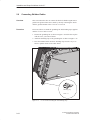
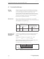
2.3
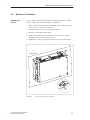
Electrical Installation
Overview
The following plug and socket connectors (interfaces) required for
connecting the various inputs and outputs of the on-board I/O of the
C7-633 P or C7-634 P are provided.
Analog Input (X14)
Analog Output (X13)
Digital Input (X12)
Digital Output (X11)
DI/DO-24V DC Power Supply
(X10)
AUX Digital Input (X10)
Figure 2-9
A View of the C7-633 P with On-Board I/O Interfaces
Digital Inputs (X12)
Table 2-1
Pin Assignments of the Digital Inputs
Pin No.
C7-633/C7-634 Control Systems
C79000-G7076-C634-01
Signal
Explanation
0.0
I0.0
Digital input 0
0.1
I0.1
Digital input 1
0.2
I0.2
Digital input 2
0.3
I0.3
Digital input 3
0.4
I0.4
Digital input 4
0.5
I0.5
Digital input 5
0.6
I0.6
Digital input 6
0.7
I0.7
Digital input 7
1.0
I1.0
Digital input 8
1.1
I1.1
Digital input 9
1.2
I1.2
Digital input 10
1.3
I1.3
Digital input 11
2-9
Installation and Setup Guidelines for the C7
Table 2-1
Pin Assignments of the Digital Inputs
Pin No.
Signal
Explanation
1.4
I1.4
Digital input 12
1.5
I1.5
Digital input 13
1.6
I1.6
Digital input 14
1.7
I1.7
Digital input 15
Digital Outputs
(X11)
Table 2-2
Pin Assignments of the Digital Outputs
Signal
Pin No.
2-10
Explanation
0.0
Q0.0
Digital output 0
0.1
Q0.1
Digital output 1
0.2
Q0.2
Digital output 2
0.3
Q0.3
Digital output 3
0.4
Q0.4
Digital output 4
0.5
Q0.5
Digital output 5
0.6
Q0.6
Digital output 6
0.7
Q0.7
Digital output 7
1.0
Q1.0
Digital output 8
1.1
Q1.1
Digital output 9
1.2
Q1.2
Digital output 10
1.3
Q1.3
Digital output 11
1.4
Q1.4
Digital output 12
1.5
Q1.5
Digital output 13
1.6
Q1.6
Digital output 14
1.7
Q1.7
Digital output 15
C7-633/C7-634 Control Systems
C79000-G7076-C634-01
Installation and Setup Guidelines for the C7
Analog Inputs X14
Table 2-3
Pin Assignments of the Analog Inputs
Explanation
Pin No.
Analog Outputs
X13
AI1-U
Analog input 1, signal input for voltage
AI1-I
Analog input 1, signal input for current
AI1-M
Analog input 1, reference potential
AI2-U
Analog input 2, signal input for voltage
AI2-I
Analog input 2, signal input for current
AI2-M
Analog input 2, reference potential
AI3-U
Analog input 3, signal input for voltage
AI3-I
Analog input 3, signal input for current
AI3-M
Analog input 3, reference potential
AI4-U
Analog input 4, signal input for voltage
AI4-I
Analog input 4, signal input for current
–
Not connected
–
Not connected
–
Not connected
Table 2-4
Pin No.
Pin Assignments of the Analog Outputs
Explanation
AO1
Analog output, signal output for voltage/current
MANA
Analog output, reference potential
AO2
Analog output, signal output for voltage/current
MANA
Analog output, reference potential
AO3
Analog output, signal output for voltage/current
MANA
Analog output, reference potential
AO4
Analog output, signal output for voltage/current
MANA
Analog output, reference potential
C7-633/C7-634 Control Systems
C79000-G7076-C634-01
2-11
Installation and Setup Guidelines for the C7
AUX Digital Inputs
X10 (Universal
Inputs)
Table 2-5
Pin Assignments of the Universal Inputs
Pin No.
Explanation
M
Relevant ground
DI-X1
Universal input 1 (digital input, interrupt input or counter input)
DI-X2
Universal input 2 (digital input, interrupt input or counter input)
DI-X3
Universal input 3 (digital input, interrupt frequency or period duration
counter input)
DI-X4
Universal input 4 (interrupt input or digital input)
Gate1
Gate for counter input DI-X1
Gate2
Gate for counter input DI-X2
Gate3
Gate for counter input DI-X3
DI/DO 24 VDC X10
Power Supply
Table 2-6
Pin Assignments of the Power Supply DI/DO
Explanation
Pin No.
2-12
1L+
24-volt supply for DI 0.0...1.7
1M
Relevant ground for DI 0.0...1.7
2L+
24-volt supply for DO0.0...DO0.7 (approx. 2 A)
2L+
24-volt supply for DO0.0...DO0.7 (approx. 2 A)
2M
Relevant ground for DO0.0...DO0.7
3L+
24-volt supply für DO1.0...DO1.7 (approx. 2 A)
3L+
24-volt supply for DO1.0...DO1.7 (approx. 2 A)
3M
Relevant ground for DO1.0...DO1.7
C7-633/C7-634 Control Systems
C79000-G7076-C634-01
Installation and Setup Guidelines for the C7
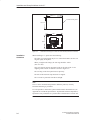
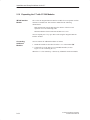
2.4
Connector Assignments
Overview
The following interfaces and connectors are present on the C7 for connecting
it to other devices. The connector assignments are listed in the following
tables.
Functional
ground
RS 232/TTY
serial interface
(X2)
Input 24 VDC
Author (X1)
Figure 2-10
24 VDC Input X1
(C7 Power
Supply)
C7-633 DP and C7-634 DP: View with Power Supply and RS 232/TTY
Serial Interface
Pin No.
Explanation
1
L+
2
M (ground M24V)
3
A+ (authorization input)
4
AI ground (authorization input)
Note
When connecting the power supply, observe the information on the 24 V DC
power supply listed in the Technical Specifications in Appendix B.1
C7-633/C7-634 Control Systems
C79000-G7076-C634-01
2-13
Installation and Setup Guidelines for the C7
RS 232/TTY (X2)
Serial Interface
Functional Ground
Pin No.
Explanation
1
C7 ground (reference potential)
2
DRxM
3
RxD
4
TxD
5
CTS
6
DTxP
7
DTxM
8
C7 ground (reference potential)
9
DRxP
10
RTS
11
--
12
C7 ground (reference potential)
13
--
14
--
15
C7 ground (reference potential)
Connect the functional ground terminal
(see Figure 2-10) to the cabinet
ground using a cable lug and a cable with a minimum cross-section of
4 mm2, taking the shortest route.
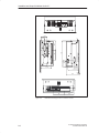
IM
(X5)
Memory Card
(X6)
MPI
(X3)
Analog Input (X14)
Analog Output (X13)
Figure 2-11
2-14
C7-633 P and C7-634 P: View with IM, MPI Interface, Memory Card,
and I/O Interface
C7-633/C7-634 Control Systems
C79000-G7076-C634-01
Installation and Setup Guidelines for the C7
IM
(X5)
Memory Card
(X6)
MPI
(X3)
PROFIBUS DP
(X4)
Figure 2-12
MPI Interface
(X3) and
PROFIBUS DP
Interface (X4)
C7-633/C7-634 Control Systems
C79000-G7076-C634-01
C7-633 DP and C7-634 DP: View with IM, MPI, and DP Interfaces, and
Memory Card
Pin No.
Explanation
1
NC
2
M24V
3
RS485 line B
4
RTSAS
5
M5V
6
P5V
7
P24V
8
RS485 line A
9
NC
2-15
Installation and Setup Guidelines for the C7
C7 Device
Connections
Table 2-7
You can use the following cables to connect the C7 to other devices:
Cables for Connecting to the C7 (see also Section 1.2)
Connecting Cable
Length Special Features
Illustration
Connection
between...
MPI
Programming device cable
PROFIBUS bus cable
Interior cable,
Direct-buried cable
and bus connector,
without PG-type socket,
with PG-type socket
and PROFIBUS bus terminal RS 485,
with 1.5 m, with 3 m cable,
with PG-type socket and 1.5 m cable
5m
-
-
User must make
own cable
C7 ´ PG/PC
C7 ´ PG/PC
C7 ´ C7
C7 ´ S7-300
C7 ´ S7-400
RS 232/TTY serial interface
Serial cable (printer cable)
See catalog
ST80.1
C7 ³ Printer
Serial cable (transfer ProTool)
See catalog
ST80.1
C7 ´ PG/PC
IM 361
IM 361 cable
2-16
-
C7 ´ additional
I/O (S7-300)
C7-633/C7-634 Control Systems
C79000-G7076-C634-01
Installation and Setup Guidelines for the C7
2.5
Connecting a Programming Device/PC to a C7
Procedure
You can connect the programming device or a PC to the multipoint interface
(MPI) of the C7 using a preassembled programming device cable.
Alternatively, you can make up the connecting cable yourself using the
PROFIBUS bus cable and bus connectors.
Figure 2-13 shows the components required for connecting a programming
device/PC to a C7.
C7
Programming device
cable (RS 232/TTY)
Programming device cable (MPI)
PG/PC
Figure 2-13
Connecting a Programming Device/PC to a C7
The C7 operator panel is loaded via the RS 232/TTY interface. The
connection to the C7 CPU is made via the multipoint interface.
Cable Lengths
You will find information on the possible cable lengths and what you should
observe when setting up an MPI or PROFIBUS DP network in the manual
/10/.
C7-633/C7-634 Control Systems
C79000-G7076-C634-01
2-17
Installation and Setup Guidelines for the C7
2.6
Connecting a Programming Device/PC to Several Nodes
Overview
When you connect a programming device or a PC to several nodes, you must
differentiate between two types of configuration:
Fixed installation of the programming device or PC in the MPI network
A programming device or PC connected for startup and maintenance
purposes.
Depending on the type you require, connect the programming device or PC
to the other nodes as follows:
Configuration Type
Fixed Installation
of Programming
Device/PC
Connection
Fixed installation of the programming
device/PC in the network
The programming device/PC is linked
directly into the MPI network
Programming device/PC connected for
startup and maintenance
The programming device/PC is connected
to one node via a spur line
With fixed installation of a programming device or PC in the MPI network,
you connect the programming device/PC via bus connectors directly to the
other nodes in the MPI network.
Figure 2-14 shows a C7 network with two C7s. The C7 devices are connected
together by means of a PROFIBUS bus cable.
C7
PG/PC
PROFIBUS bus cable
C7
MPI
Figure 2-14
2-18
Connecting a Programming Device/PC to Several C7 Devices
C7-633/C7-634 Control Systems
C79000-G7076-C634-01
Installation and Setup Guidelines for the C7
Connecting a
Programming
Device/PC for
Service Purposes
If there is no stationary programming device or PC available, we recommend
the following procedure:
In order to connect a programming device or PC for service purposes to an
MPI network with “unknown” node addresses, we recommend you set the
following address on the service programming device/PC:
MPI address: 0
Highest MPI address: 126.
Then work out the highest MPI address in the MPI network using the STEP 7
application Configuring Hardware and adjust the highest MPI address on the
programming device or PC to match the highest address of the MPI network.
Programming
Device/PC for
Startup and
Maintenance
For startup and maintenance purposes, you connect the programming
device/PC via a spur line to a node in the MPI network. To do this, the bus
connector of this node must have a PG-type socket.
Figure 2-15 shows two networked C7s to which a programming device/PC is
connected.
PG cable
= spur line
C7
PG/PC
C7
PROFIBUS bus cable
Figure 2-15
C7-633/C7-634 Control Systems
C79000-G7076-C634-01
Connecting a Programming Device/PC to an MPI Network
2-19
Installation and Setup Guidelines for the C7
2.7
Setup Guidelines for Interference-Free Installation
Overview
An automation system must be shielded to prevent interference.
When a system is poorly grounded or not shielded, low-frequency or
high-frequency interference signals can penetrate through to the internal bus
of the controller and cause malfunctions.
Interference signals can also be caused when relays or contactors switch
(very rapid changes in current or voltage; high-frequency interference
signals) or when two parts of a system have different grounding potentials
(low-frequency interference signals).
Use and
Installation of
Interference-Free
Cables
Use only shielded cables for all signal lines.
Ground cable shields on both sides for:
– Cables to the programmable controller
– Bus cables
– Cables to I/O devices.
The standard cables specified in the ST80.1 catalog meet these
requirements.
Screw or lock all plug-type connections.
Do not install signal lines parallel to power lines. Use a separate cable
duct located at least 50 cm from the power lines.
Cabinet
Installation
Devices which could bring in interference signals from outside should be
installed at the bottom of the cabinet. Place the grounding rail immediately at
the cabinet entrance so that cables which could be carrying interference
signals can be placed directly on the grounding potential. Place all shielded
lines with their shielding here. With double-shielded signal lines, place only
the outer shield on the grounding potential.
Install long signal lines along the cabinet walls. Cabinet design in accordance
with EMC guidelines is an important factor in the reduction of interference.
All grounding connections in the cabinet must have large cable cross-sections
and be laid over a large area.
Insulate analog devices in the switching cabinet and ground them to a single
point in the cabinet using copper tape.
Always use equivalent metals for the materials. Never use aluminum (danger
of oxidation).
2-20
C7-633/C7-634 Control Systems
C79000-G7076-C634-01
Installation and Setup Guidelines for the C7
Connect all doors and metal parts (sides, back panel, and cover) of the
cabinet at least three times to the cabinet frame (short, paint-free, and
large-area connections).
Note
If your system generates high electrostatic voltages (for example, textile
machines, special construction machines), run the grounding lines of the
machine parts carrying interference signals to a separate operating ground
isolated from the central grounding point of the cabinet (surface grounding
with building construction, reinforcement).
Protection Against
Overvoltage
Observe the guidelines in Section 4.11 of the manual /10/ to protect against
overvoltage and lightning strikes.
Observe the guidelines in Section 4.8 of the manual /10/ for laying cables
within buildings.
C7-633/C7-634 Control Systems
C79000-G7076-C634-01
2-21
Installation and Setup Guidelines for the C7
2.8
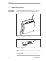
Connecting Shielded Cables
Overview
This section describes how to connect the shield of shielded signal lines to
ground. The ground connection is made by directly connecting the shield
with the ground terminal of the C7-633 P or C7-634 P.
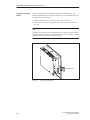
Procedure
Proceed as follows to install the grounding bar and shielding clips supplied
with the C7-633 P and C7-634 P:
1. Position the grounding bar as shown in Figure 2-16 and fix this in place
with the screw you removed earlier.
2. Attach the shielding clips to the grounding bar as shown in Figure 2-16.
3. Press the insulated cable into these shielding clips in such a way as to
achieve optimal contact of the cable shield.
Shielding clip
Scale 1:1
Figure 2-16
2-22
C7-633 P with Grounding Bar and Shielding Clips
C7-633/C7-634 Control Systems
C79000-G7076-C634-01
Installation and Setup Guidelines for the C7
2.9
Encoding Connectors
Overview
A set of connectors with solid and profiled coding keys can be ordered as
C7-633 P or C7-634 P accessories (see Section 1.2 under Accessories). The
keying of connectors will be described in the following:
Keying
Connectors
The solid coding keys À and profiled coding keys Á (see Figure 2-17)
prevent a connector from being confused with another without polarity
reversal.
Proceed as follows:
1. Insert the solid coding key À into the notches provided on the connector
part ¶.
2. Insert the profiled coding key Á into the respective cutouts on the housing
part ·.
Solid and profiled coding keys that face each other prevent the connector
from being plugged in.
The connector can be plugged in if solid and profiled coding keys do not face
each other.
10
9
·
Á
8
7
6
5
4
3
2
1
À
Figure 2-17
C7-633/C7-634 Control Systems
C79000-G7076-C634-01
The Coding Ensures that the Correct Connector is Inserted
2-23
Installation and Setup Guidelines for the C7
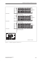
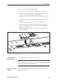
2.10 Expanding the C7 with S7-300 Modules
IM 360 Interface
Module
The C7 has an integrated IM 360 interface module for I/O expansion with an
external S7 standard I/O. This interface module has the following
characteristics:
Data transmission from the IM 360 to the IM 361 of the first rack
expansion via a 368 connecting cable
Maximum distance between IM 360 and IM 361 is 10 m.
You can expand your C7 by up to three racks using the integrated IM 360
interface module.
Connecting
Additional
Modules
You can connect the additional modules as follows:
1. Install the modules as described for racks 1 to 3 in the manual /10/.
2. Connect the C7 to the IM 361 via a standard IM cable (see also
Figure 2-12 for connecting the C7).
When the C7 is first started up, it detects any additional connected modules.
2-24
C7-633/C7-634 Control Systems
C79000-G7076-C634-01
Installation and Setup Guidelines for the C7
Rack 3
Slot number
IM-361
3
4
5
6
7
8
9
10
11
368 connecting cable
Rack 2
IM-361
Slot number
3 4
5
6
7
368 connecting cable
8
9
10
11
Rack 1
Slot number
IM-361
3
4
5
6
7
8
9
10
11
368 connecting cable
Slot number 2
Figure 2-18
3
4*) 5*)
*) only for C7-63x P
Maximum Configuration of the Slots of a C7
C7-633/C7-634 Control Systems
C79000-G7076-C634-01
2-25
Installation and Setup Guidelines for the C7
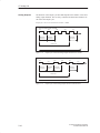
2.11 Configuring an MPI and PROFIBUS DP Network
You can integrate the C7 devices in an MPI network via the MPI and
configure a PROFIBUS DP network via the PROFIBUS DP interface (only
for C7-633 DP or C7-634 DP).
You will find the procedures for configuring an MPI network and
PROFIBUS DP network in the manual /10/.
2-26
C7-633/C7-634 Control Systems
C79000-G7076-C634-01
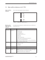
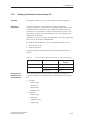
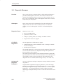
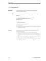
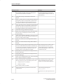
3
Special Features of C7
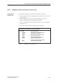
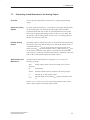
Chapter
Overview
C7-633/C7-634 Control Systems
C79000-G7076-C634-01
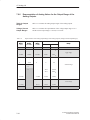
Section
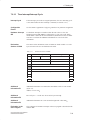
Description
Page
3.1
Variations from the Individual Components CPU and OP
3-2
3.2
Selecting a C7 CPU Operating Mode
3-4
3.3
DI/DO Status Displays
3-6
3.4
Status and Error Indicators on the C7 CPU
3-7
3-1
Special Features of C7
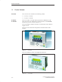
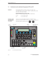
3.1
Variations from the Individual Components CPU and OP
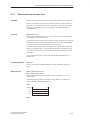
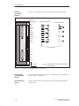
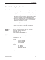
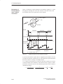
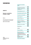
Keyboard
The arrangement and color of the keys on the C7-633 and C7-634
corresponds mainly to those of the OP 7 and OP 17 operator panels (see the
OP7, OP17 Control Panels manual).
Extended OP function keys on the C7-633:
The C7-633 and the OP 7 differ in their number of function keys:
Selecting a CPU
Operating Mode
Using Keys
C7 CPU
status LEDs
C7-633:
F1 to F4 and K1 to K16
OP 7:
F1 to F4 and K1 to K4
A CPU is set to the modes MRES, STOP, RUN, and RUN-P using a
mechanical keyswitch. On both C7 devices, this keyswitch is emulated as an
electronic keyswitch by means of the keys
Function keys
and
.
Softkeys
CPU operating mode
selection keys
SIMATIC C7-633
SF
R–P
BATF
R
DC5V
FRCE
F1
RUN
F3
F2
S
F4
M
STOP
K1
SF–IM
K2
K3
K6
K7
K8
,E./
:,-'A
7
8
D
4
K10
9
E
5
A
1
2
K12
K13
K14
K15
K16
0
ESC
.
ACK
F
6
B
K11
3
C
Numeric keys
3-2
K5
BUSF
K9
Figure 3-1
K4
SF–DP
SHIFT
System keys
INS
DEL
HELP
ENTER
System key
LEDs
C7-633 with Keyboard and Display
C7-633/C7-634 Control Systems
C79000-G7076-C634-01
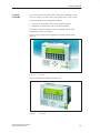
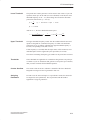
Special Features of C7
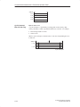
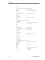
SIMATIC C7-634
All other keys are
identical to those of
the C7-633
F1
Figure 3-2
F2
F3
F4
F5
F6
F7
F8
C7-634 with Keyboard and Display
C7-633/C7-634 Control Systems
C79000-G7076-C634-01
3-3
Special Features of C7
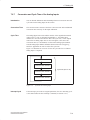
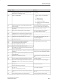
3.2
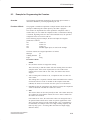
Selecting a C7 CPU Operating Mode
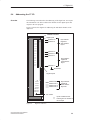
Changing the
C7 CPU Operating
Mode
You select the CPU operating modes RUN-P, RUN, STOP, and MRES as
follows:
Each time the mode selector key is pressed, the CPU mode changes. The key
must remain pressed for at least 500 ms for the mode change to take place
and the corresponding LED to light up.
To prevent an uncontrolled C7 CPU operating mode transition during control
operation, the key function can be activated or deactivated via an external
authorization input. When the authorization input is activated, operating
mode selection is active and the current CPU mode is displayed by an LED.
When the authorization input is deactivated, all status LEDs are off.
The authorization input is located on the same connector as the C7 power
supply (see Section 2.4).
3-4
Authorization activated:
A+
AI
bridged
Authorization deactivated:
A+
AI
open
C7-633/C7-634 Control Systems
C79000-G7076-C634-01
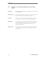
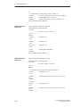
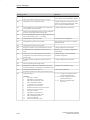
Special Features of C7
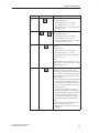
Mode
Key
Explanation / Procedure
RUN-P
The C7 CPU processes the user program.
(R-P)
Programs and data can be:
S Read out from the C7 CPU with the
programming device (C7 ³ PG)
S Downloaded to the C7 CPU and changed
there (PG ³ C7).
RUN
(R)
The C7 CPU processes the user program.
or
Programs and data can be:
S Read out from the C7 CPU with the
programming device (C7 ³ PG).
S cannot be downloaded to the C7 CPU and
changed there (PG ³ C7).
STOP
(S)
The C7 CPU does not process the user
program.
Programs can be:
S Read out from the C7 CPU with the
programming device (C7 ³ PG)
S Downloaded to the C7 CPU and changed
there (PG ³ C7).
Note:
The STOP mode is only valid for the C7 CPU
and not for the C7 OP. It is possible to continue
working with the C7 OP.
MRES
Memory Reset
(M)
Executing a memory reset on the C7 CPU
(clear memory, reload user program from flash
memory if a memory card is inserted) requires a
special sequence of operations with the modes
STOP and MRES:
1. Select STOP mode by pressing the DOWN
key. The key must remain pressed for at
least 300 ms for the transition to take place.
The key LED “S” and the CPU status LED
“STOP” light up.
2. Select the mode MRES by keeping the
DOWN key depressed. The key LED “M”
lights up. Immediately after the second time
the CPU status LED “STOP” lights up,
release the key briefly and press it again.
After flashing briefly, it then remains lit.
Note:
If data were deleted during the memory reset
which were required by the C7 OP
configuration, the C7 OP reports this using an
error message.
C7-633/C7-634 Control Systems
C79000-G7076-C634-01
3-5
Special Features of C7
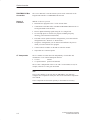
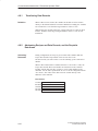
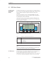
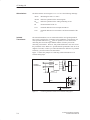
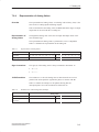
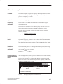
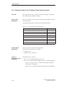
3.3
DI/DO Status Displays
Configuring the
DI/DO Status
Display
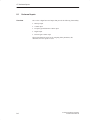
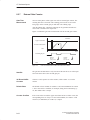
The DI/DO status display is not a system function but a configured image of
the C7 OP. You can create the DI/DO status display image yourself or copy it
from the standard configuration supplied with ProTool (image name:
Z_DI_DO).
The values represented are read as a direct process image of the digital
inputs and an internal process image of the digital outputs of the digital
C7 I/O and displayed in binary format (BIN).
Note that the last state set by the program is displayed, although the real
process state of the digital outputs is 0 when the C7 CPU is in STOP mode.
The following data are supplied:
À
Á
= Anwahl
der
DI:11101110
0.7-0.0
10101010 1.7-1.0
DO:11101110 0.7-0.0
10101010 1.7-1.0
F1
F2
F3
F4
Figure 3-3
DI/DO Status Display on a C7-633 P
Table 3-1
Explanation of the DI/DO Display in Figure 3-3
Explanation
Position
À
Signal status of the DI/DO
S 1 DI/DO set
S 0 DI/DO reset
Á
Pin no. from - to
Note
The values of the digital I/O are read in and displayed every 400 ms. Any
changes which occur between these times are not displayed.
C7 CPU Access
3-6
The DI/DO image of the standard configuration accesses the digital I/Os of
the first configured programmable controller. Therefore, the first
programmable controller in the list should always be the C7 CPU. Otherwise
it is necessary to adapt the programmable controller access for the image.
C7-633/C7-634 Control Systems
C79000-G7076-C634-01
Special Features of C7
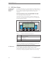
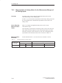
3.4
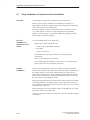
Status and Error Indicators on the C7 CPU
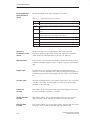
Status and Error
Indicators
The C7 has the following status and error indicators:
SF
BATF
DC5V
FRCE
RUN
STOP
SF-IM
SF-DP
BUSF
Figure 3-4
Meaning of the
Status and Error
Indicators
LED
SF (red)
Status and Error Indicators on the C7
The status and error indicators are explained in the order in which they are
positioned on the C7.
Meaning
C7 CPU
group error
Explanations
Lights up for
S
S
S
S
S
S
S
S
S
Hardware faults
Firmware faults
Programming errors
Parameter assignment errors
Math errors
Time errors
Faulty internal memory
Battery failure or backup missing on POWER ON
I/O error in the internal I/O functions
To determine the error/fault more exactly, you must use the programming
device and display the diagnostic buffer.
BATF (red)
Battery fault
Lights up if the battery
S Has too low voltage
S Is defective
S Is missing
DC5V (green)
5 VDC supply for C7 Lights up if the internal 5 VDC supply is functioning correctly
FRCE (yellow)
Force job
Lights up when a force job is active
RUN (green)
RUN mode for the
C7 CPU
Lights up when the C7 CPU user program is being processed.
Flashes (2 Hz) during C7 CPU startup (then the STOP LED also lights up;
when the STOP LED goes out, the outputs are enabled).
Flashes (2 Hz) when the CPU is in HOLD mode.
C7-633/C7-634 Control Systems
C79000-G7076-C634-01
3-7
Special Features of C7
LED
STOP (yellow)
SF-IM (red)
Meaning
STOP mode for the
C7 CPU
Lights up when the C7 is not processing a CPU user program.
Interface module
group error
Lights up when the connection between the C7 and the expansion rack is
faulty.
Display Elements
for PROFIBUS
SF-DP
(red)
BUSF
(green)
On
On
Explanations
Flashes in 1-second intervals if the C7 CPU requires a memory reset
(MRES).
The following table explains the meaning of the LEDs which are assigned to
the PROFIBUS DP. Refer also to Chapter 11 in the manual /70/.
Meaning
S Bus fault (physical fault)
Remedy
S Check the bus cable for short circuit or wire
break
S DP interface fault
S Different transmission rates in
S Evaluate diagnostics, reconfigure or correct
errors if necessary
multi-master operation
On
Flashing
S Station failed
S Check the bus cable is connected correctly,
check for short circuits or wire breaks
S At least one of the assigned slaves cannot S Wait until the C7 has completed its startup
be addressed
S If flashing does not cease, check the DP
slaves and evaluate diagnostics
On
Off
S DP configuration missing or faulty (also if S Evaluate diagnostics, reconfigure or correct
CPU was not set as DP master)
Off
3-8
Off
errors if necessary
S No error
C7-633/C7-634 Control Systems
C79000-G7076-C634-01
Communication between the CPU and the
Operator Panel
In This Chapter
4
This chapter provides you with information on configuration parameters that
are necessary for the communication between the C7 OP and the C7 CPU.
The communication is achieved using two data areas:
S The user data area
and/or
S The interface area.
The functions, structure, and special features of the various user data areas
and the interface areas are described in this chapter.
For those who are not yet familiar with OPs, we recommend the manual First
Steps with ProTool/Lite.
Chapter
Overview
Section
Page
4.1
Configured Communications Parameters
4-2
4.2
Overview of User Data Areas
4-3
4.3
Event and Alarm Messages
4-4
4.4
Keyboard and LED Image
4-8
4.4.1
System Keyboard Image
4-9
4.4.2
Function Keyboard Image
4-10
4.4.3
LED Image
4-11
4.5
Screen Number Area
4-12
4.6
User Version
4-13
4.7
Interface Area
4-14
4.7.1
Control and Checkback Bits
4-15
4.7.2
Data Areas in the Interface Area
4-17
Recipes
4-19
4.8.1
Transferring Data Records
4-20
4.8.2
Addressing Recipes and Data Records, and the Requisite
Data Areas
4-20
4.8.3
Synchronization during Transfer - Normal Case
4-21
4.8.4
Synchronization during Transfer - Special Cases
4-22
4.9
Notes on Optimization
4-23
4.10
Data Exchange via the Interface Area
4-24
Example of How to Activate a Control Job
4-31
4.8
4.10.1
C7-633/C7-634 Control Systems
C79000-G7076-C634-01
Description
4-1
Communication between the CPU and the Operator Panel
4.1
Configured Communications Parameters
Parameters
In the configuration software, the following parameters are to be set for
communication via the MPI:
Note
The following parameters are already assigned generally applicable default
values and need not be modified unless the C7 is used in connection with
any other S7, C7, or OP units in a network.
Parameter
Configuration Tool
4-2
Explanation
CPU type
CPU in programmable controller
The S7-300 is to be set for the C7 CPU. If further CPUs are
connected, they must be set with S7-300 or S7-400.
CPU address
MPI address of the C7 CPU in the network configuration. The
default address is 2. The address can be freely assigned. It must
be unique in a network.
Slot/rack
Here you must set the slot and rack. For the C7 CPU, the
setting is:
Slot 2
Rack 0
C7 OP address
MPI address of the C7 OP in the network configuration. The
address can be freely assigned. It must be unique in the
network configuration. The default value is address 1.
Interface
Here, you determine which interface of the OP the C7 CPU is
connected to.
Transmission rate
The data transfer rate between the C7 OP and the C7 CPU can
be set between 19.2 Kbps and 1.5 Mbps.
All settings can be made with ProTool and ProTool/Lite under the menu
command System → PLC .
C7-633/C7-634 Control Systems
C79000-G7076-C634-01
Communication between the CPU and the Operator Panel
4.2
Overview of User Data Areas
User Data Areas
User data areas are used to exchange data between the C7 CPU and the
C7 OP. It is by means of these data areas that the C7 CPU and the C7 OP
communicate.
The communication process consists of the C7 OP and the user program
alternately writing and reading information into and out of the data areas.
Upon evaluation of the data, the C7 CPU and the C7 OP are triggered into
the various actions.
The user data areas can reside in any required memory area in the C7 CPU.
Functionality
The following user data areas are possible:
S Event messages
S Alarm messages
S Control jobs
S Recipes
S System keyboard image
S Function keyboard image
S LED image
S Cyclic intervals (C7-634 only)
S Date and time
S Screen number area
S User version
C7-633/C7-634 Control Systems
C79000-G7076-C634-01
4-3
Communication between the CPU and the Operator Panel
4.3
Event and Alarm Messages
Message
Triggering
Messages are triggered by setting a bit in one of the message areas in the
C7 CPU. The location of the message area is defined by the configuration
tool. The corresponding area must also be defined in the C7 CPU.
As soon as the bit in the event or alarm message area of the C7 CPU is set
and transferred to the C7 OP, the message is recognized as having “arrived”.
Conversely, after resetting the same bit in the C7 CPU, the message is
registered in the C7 OP as having “departed”.
Message Areas
Table 4-1 represents the number of message areas for event and alarm
messages and alarm acknowledgement areas, as well as the total length of all
areas, for both the C7-633 and the C7-634.
Table 4-1
Event message area
Device
Message Bit and
Message Number
Assignment
Message Areas of the C7 OP
Alarm message area and alarm
message acknowledgement area
Number
Length (words)
Number of
each type
Total length of each
type (words)
C7-633
4
32
4
32
C7-634
4
64
4
64
A message can be configured for every bit in the configured message area.
The bits are assigned to the message numbers in ascending sequence.
Example:
The following event message area is configured for the C7 CPU:
DB 60
Length 5 (in words)
Address 42
Figure 4-1 shows the assignment of all 80 (5 x 16) message numbers to the
individual bit numbers in the control event message area.
The assignment follows automatically in the C7 OP.
Figure 4-1
4-4
Assignment of Message Bit and Message Number
C7-633/C7-634 Control Systems
C79000-G7076-C634-01
Communication between the CPU and the Operator Panel
Acknowledgement
As alarm messages indicate faulty behavior of some sort, these must be
acknowledged. Acknowledgement follows either by:
S Taking appropriate action on the C7 or
S Setting a bit in the acknowledgement area of the C7 CPU.
Acknowledgement
Area
If the C7 CPU is to be informed about an acknowledgement of an alarm
message at the C7 OP itself, or if the acknowledgement should be given by
the C7 CPU, the corresponding acknowledgement areas are to be configured
in the C7 CPU:
S Acknowledgement area C7 OP ! C7 CPU:
The programmable controller is informed when an alarm message is
acknowledged by an operation at the OP.
S Acknowledgement area C7 CPU ! C7 OP:
The alarm message is acknowledged via the C7 CPU.
These acknowledgement areas are to be allocated in the configuration; when using ProTool and ProTool/Lite, under “area pointers”. Figure 4-2
shows schematically the individual alarm message and acknowledgement
areas
Alarm message area
Internal processing /
linking
Acknowledgement area
C7 CPU ! C7 OP
Acknowledgement area
C7 OP ! C7 CPU
Figure 4-2
Assignment of
Acknowledgement
Bit to Message
Number
Alarm Message and Acknowledgement Areas
Every alarm message has a message number. To this message number, the
same bit of the alarm message area and the bit multiplying of the
acknowledgement area are assigned. This is also valid for more than one
acknowledgement area, if the length of the previous acknowledgement area
does not encompass the entire length of the alarm message area. Figure 4-3
clarifies this situation.
Alarm message no. 1
Acknowledge bit for alarm message no. 1
Alarm message no. 49
Acknowledge bit for alarm message no. 49
Figure 4-3
C7-633/C7-634 Control Systems
C79000-G7076-C634-01
Assignment of Acknowledge Bit and Message Number
4-5
Communication between the CPU and the Operator Panel
Acknowledgement
Area C7 CPU →
C7 OP
One of the bits set in the C7 CPU area, causes the acknowledgement of the
corresponding alarm message at the C7 OP. Reset this bit when you reset the
bit in the alarm message area. Figure 4-4 shows the timing diagram.
The acknowledgement area C7 CPU
C7 OP
S Must be immediately connected to the relevant alarm message area
S Must have exactly the same polling time and
S Can have the same maximum length as the corresponding alarm message
area.
If the acknowledgement area C7 CPU → C7 OP is not physically located
behind the alarm message area, the system message $655 is issued when the
device starts up.
Alarm message area
Acknowledgement
area C7 CPU →
C7 OP
Figure 4-4
Acknowledgement
Area C7 OP
C7 CPU
Acknowledgement
via C7 CPU
Pulse Diagram for Acknowledgement Area C7 CPU → C7 OP
If a bit is set in the alarm message area, the CP OP sets the corresponding bit
in the acknowledgement area. If an alarm message is acknowledged at the
C7 OP, the corresponding bit is set in the acknowledgement area C7 OP
C7 CPU. In this way, the S7 can recognize that the alarm message has been
acknowledged.
The acknowledgement area C7 OP
C7 CPU can have the same maximum
length as the corresponding alarm message area.
Alarm message area
Acknowledgement area
C7 OP → C7 CPU
Acknowledgement
via C7 OP
Figure 4-5
4-6
Pulse Diagram forAcknowledgement Area C7 OP → C7 CPU
C7-633/C7-634 Control Systems
C79000-G7076-C634-01
Communication between the CPU and the Operator Panel
Size of the
Acknowledgement
Areas
The acknowledgement areas may not be larger than the corresponding alarm
message area. It can, however, be configured to be smaller if it is not
necessary to acknowledge every alarm message. Figure 4-6 clarifies this
case.
Alarm message area
Alarm messages
that can be
acknowledged
Alarm messages
that cannot be
acknowledged
Figure 4-6
Reduced alarm message
acknowledgement area
Reduced Acknowledgement Area
Note
Allocate important alarm messages, whose acknowledgement is to be
signaled to the C7 CPU in the alarm message area from bit 0 in ascending
order!
The two related bits in the alarm message area and the acknowledgement
area must not be set simultaneously.
C7-633/C7-634 Control Systems
C79000-G7076-C634-01
4-7
Communication between the CPU and the Operator Panel
4.4
Keyboard and LED Image
Application
Key actions on the C7 OP can be transferred to the C7 CPU and evaluated
there. In this way, actions can be triggered in the C7 CPU (for instance,
switching on a motor).
The LEDs in the C7’s function keys can be controlled from the C7 CPU. In
this way, active LEDs can be used in different situations to signal to the
operator which key they should press.
Prerequisite
In order to make use of this function, you must:
S Set up corresponding data areas (images) in the C7 CPU
S Specify these data areas as “area pointers” during the configuration
S Assign the bits from the “area pointers” to these data areas on configuring
the function keys.
Transfer
The keyboard images are transferred spontaneously to the C7 CPU. That
means the transfer always happens if a change is registered at the C7 OP. In
this case you do not need to configure a polling time. A maximum of two
simultaneous key actions can be transferred at one time.
Value Allocation
S
All keys (except SHIFT key)
As long as the corresponding key is pressed, the assigned bit in the
keyboard image has the value 1, otherwise it has the value 0.
Bit value
1
0
t
= Key pressed
S SHIFT key
When the SHIFT key is first pressed, the assigned bit in the keyboard
image receives the value 1. This state remains even after releasing the
key until the SHIFT key is pressed again.
Bit value
1
0
4-8
t
= SHIFT key
pressed
C7-633/C7-634 Control Systems
C79000-G7076-C634-01
Communication between the CPU and the Operator Panel
4.4.1
System Keyboard Image
Layout
The system keyboard image is a data area with a fixed length of two data
words.
Every key of the system keyboard is assigned exactly one bit in the system
keyboard image, with the exception of the cursor keys.
The system keyboard image must also be specified as “area pointer, type:
system keyboard” in the configuration. This image can be assigned once only
and in one CPU.
Keyboard image:
Bit number
15 14 13 12
+/Ć
.
11 10
SHIFT
9
8
7
INS
DEL
9
6
5
4
ENTER
8
7
F
6
3
2
ESC
E
5
4
D
C
3
1
0
ACK HELP
B
2
1
A
0
1st word
2nd word
Keyboard group bit
Note
Unused bits may not be overwritten by the user program.
Keyboard Group
Bit
The keyboard group bit serves as the control bit. It is set to the value 1 for
each transfer of the keyboard image from the C7 OP to the C7 CPU. After
evaluation of the data area by the user program, it should be reset.
You can determine whether a block has been transferred again by regularly
reading the group bits with the user program.
C7-633/C7-634 Control Systems
C79000-G7076-C634-01
4-9
Communication between the CPU and the Operator Panel
4.4.2
Function Keyboard Image
Data Areas
The image of the function keyboard can be categorized into separate data
areas:
S Maximum number of data areas - 4
S Total length of all data areas (words) - 4
Key Assignment
The assignment of the individual keys to the data area bits is defined when
the function keys are configured. The number within the image area is
declared for every key.
The function keyboard image must also be specified in the configuration,
under “area pointer, type: function keyboard”.
Keyboard Group
Bit
The most significant bit in the last data word of every data area is the
keyboard group bit. It serves as a control bit. This bit is set to 1 for every
transfer of the keyboard image. After evaluation of the data area by the user
program, the keyboard group bit should be reset.
You can determine whether a block has been transferred again by regularly
reading the group bits with the user program.
4-10
C7-633/C7-634 Control Systems
C79000-G7076-C634-01
Communication between the CPU and the Operator Panel
4.4.3
LED Image
Data Areas
The LED image can be categorized into separate data areas.
S Maximum number of data areas: 4 (for example, 4 different data areas in
various CPUs)
S Total length of all data areas (words) 8:
The LED image must also be specified under “area pointer, type: LED
image” in the configuration.
LED Assignment
The assignment of the individual LEDs to the data area bits is defined when
the function keys are configured. The bit number within the image area is
declared for every LED.
The K keys in the C7 OPs have two-colored LEDs (red and green).
The bit number (n) denotes the first of two consecutive bits, which can
control four different LED states in total:
C7-633/C7-634 Control Systems
C79000-G7076-C634-01
Bit n + 1
Bit n
LED Function
0
0
Off
0
1
Flashing red
1
0
Permanently red
1
1
Permanently green
4-11
Communication between the CPU and the Operator Panel
4.5
Screen Number Area
Application
The C7 OP stores information concerning the image displayed on the C7 OP
in the screen area number.
It is thus possible to transfer information about the current display contents
from the C7 OP to the C7 CPU, and from there, to trigger certain reactions,
for example, displaying another image.
Requirement
If the screen number area is to be used, it must be specified as an “area
pointer” in the configuration. It can only be stored once and in one C7 CPU.
The screen number area is transferred spontaneously to the controller. That
means the transfer always happens if a change is registered at the C7 OP. In
this case you do not need to configure a polling time.
Layout
The screen number area is a data area with a fixed length of 2 data words.
The layout of the screen number area for the C7 OP in the memory of the
controller is represented below.
7
0 7
Current screen type
1st word
Current entry number
2nd word
0
Current screen number
Current input field number
Entry
Assignment
Current screen type
1: Image
2: Recipe
3: Special image
Current screen/recipe number
1 to 99
Current entry number
1 to 99
Current input field number
0 to 8
0: Entry number
All bytes of the screen number area are assigned with FF in the message
level and for the display of a contents directory.
For special screens the screen number area is assigned as follows:
7
4-12
0
7
0
1st word
3
Special screen number
2nd word
FFH
Current input field number
C7-633/C7-634 Control Systems
C79000-G7076-C634-01
Communication between the CPU and the Operator Panel
4.6
User Version
Verwendung
You can check whether the C7 OP is connected to the right controller on
startup.
The C7 OP compares a value stored in the C7 CPU with the configured
value. This ensures that the configuration data are compatible with the C7
CPU. If the values do not match, the system message $653 is displayed on
the C7 OP and the device is restarted.
To use this function, preset the following values when configuring the
C7 OP:
S Version number of the configuration (value between 1 and 255) under
System → Settings
S Data type and address of the value stored in the controller for the version:
System → Area Pointers,
Select User Version in the Type: field.
C7-633/C7-634 Control Systems
C79000-G7076-C634-01
4-13
Communication between the CPU and the Operator Panel
4.7
Interface Area
Overview
The interface area is only necessary for the C7 CPU if its functions are to be
used or evaluated by the C7 CPU.
The interface area must be configured if you want to use the following
functions:
– Send control jobs to the C7 OP
– Synchronize date and time between the C7 CPU and the C7 OP
– Evaluate coupling identifier
– Recipes (transferring data records)
– Recognize C7 OP startup in the C7 CPU program
– Evaluate the C7 OP operating mode in the C7 CPU program
– Evaluate the C7 OP’s ready bit in the C7 CPU program
– Set cyclic interrupts (C7-634 only)
Layout of the
Interface Area
Figure 4-7 shows the layout of the interface area. You can define the interface
area in a data block or a memory area. The address of the interface area should
be specified in the configuration. This is necessary so that the OP knows where
to put the data.
The interface area should be created once per CPU.
Interface area:
0
Address 7
n+0
Control / checkback bits
n+4
Job area
n+12
n+13
n+14
n+15
Reserved
Coupling identifier
Reserved
Time
n+18
Reserved
n+21
n+25
n+26
Date
Reserved
Cyclic interrupt bits
n+31
Figure 4-7
4-14
Layout of the Interface Area for the C7 CPU
C7-633/C7-634 Control Systems
C79000-G7076-C634-01
Communication between the CPU and the Operator Panel
4.7.1
Control and Checkback Bits
Introduction
Three bytes are available in the interface area for the control and checkback
bits. Bytes n+0 and n+1 are used to coordinate between the C7 OP and the
C7 CPU. Byte n+3 is required for the transfer of data records and indirect
variables.
Byte n+0, n+1, and n+3 are described below.
Description of
Byte n+0
The structure of byte n+0 is shown below. The diagram is followed by a
description of the individual bits.
Address
n+0
7 6
5
4
3
2 1
0
Cyclic interrupt bit
Time
Date
Bits 5-6 Date/time
1 = New
The transfer of the date and time from the C7 OP to the C7 CPU
can be initiated by means of control job 41. These bits are set by
the C7 OP if a new date or a new time is transferred. The bits must
be reset in the control program after the date or time has been
evaluated.
Bit 7
Cyclic interrupt bit:
1 = New
The cyclic interrupt bit is possible only for the C7-634.
If the C7-634 has set a new cyclic interrupt bit in the interface area,
it also sets the corresponding bit in the control and checkback bits.
You therefore need only scan this bit to detect a change in the cyclic
interrupt bit. Following evaluation, the bit has to be reset in the S7
program.
Description of
Byte n+1
The following diagram shows the layout of byte n+1. Afterwards follows the
description of the individual bits.
Address
n+1
7
6
5
4
3
2
1
0
C7 OP ready bit
C7 OP operating mode
C7 OP startup
C7-633/C7-634 Control Systems
C79000-G7076-C634-01
4-15
Communication between the CPU and the Operator Panel
Bit 0
C7 OP startup
1 = C7 OP has been started
Bit 0 is reset by the C7 OP following startup. You can reset the bit
in the C7 CPU program and thus recognize when the C7 OP is
being restarted.
Bit 1
C7 OP operating mode
1 = C7 OP in offline mode
0 = C7 OP in normal mode
Bit 1 is set if the operator switches the C7 OP to offline. The bit
has a value 0 in an online condition.
Bit 2
Description of
Byte n+3
C7 OP ready bit
The C7 OP inverts the ready bit within 1 second. In the C7 CPU
program, you can recognize whether a connection to the C7 OP
exists.
Byte n+3 serves to synchronize the transfer of data records and indirect
variables. The meanings of the individual bits are described below. Exactly
how the transfer works is described in Section 4.8.3.
Bit 0 1 = Data mailbox is disabled (set only by the C7 OP)
0 = Data mailbox is enabled
Bit 1 1 = Data record/variable is faulty
Bit 2 1 = Data record/variable is correct
Bit 3 1 = Data transfer completed
Bit 4 1 = Request data record/variable
Bit 5 1 = C7 OP should read data mailbox
Bit 6 1 = Request data mailbox disable
Bit 7 1 = C7 OP has read data mailbox
(with transfer C7 CPU→C7 OP)
4-16
C7-633/C7-634 Control Systems
C79000-G7076-C634-01
Communication between the CPU and the Operator Panel
4.7.2
Data Areas in the Interface Area
Overview
In this section, the structure and use of the interface data areas are described.
The C7 CPU initiates an action to be carried out on the C7 OP by means of
the job area. All other bytes are areas in which the C7 OP writes data. These
areas can be evaluated by the C7 CPU program. The individual bytes are
described below.
Job Area
Bytes n+4 to n+11:
Control jobs can be passed on to the C7 OP via the job area. The actions on
the C7 OP are initiated in this way.
The job area consists of four words. In the first word of the job area is the job
number. In the other words, the job parameters are to be entered (maximum
3). Figure 4-8 shows the general structure of a control job.
If the first word of the job area is not equal to zero, the C7 OP evaluates the
control job. After that, the C7 OP sets this data word to zero again. For this
reason, the parameters must first be entered in the job area and only then the
job number.
The possible control jobs are listed with job numbers and parameters in
Section 4.10.
Coupling Identifier
Byte n+13:
The C7 OP enters the coupling identifier 0 for the multipoint interface in
byte 13.
Date and Time
Time = bytes n+15 to n+17
Date = bytes n+21 to n+24
The date and time can be transferred from the C7 OP to the C7 CPU via
control job 41.
The following screens show the structure of the data area. All inputs are
coded in Binary Coded Decimal (BCD).
Time:
Address
7
0
n+15
Hours (0...23)
n+16
Minutes (0...59)
n+17
Seconds (0...59)
Date:
C7-633/C7-634 Control Systems
C79000-G7076-C634-01
4-17
Communication between the CPU and the Operator Panel
Address
7
0
Weekday (1...7)
n+21
Cyclic Interrupt
Bits (C7-634 only)
n+22
Day (1...31)
n+23
Month (1...12)
n+24
Year (0...99)
Bytes n+26 to n+31:
A cyclic interrupt is a periodically recurring point in time (hourly, daily,
weekly, annually) at which a predefined function is executed - for example:
S Print message buffer or screen
S Select screen.
When a cyclic interrupt is reached on the C7 OP, the corresponding bit is set
in this area:
Address
n + 26
n + 30
7
0 7
0
16
1
32
17
48
33
Cyclic Interrupt No.
4-18
C7-633/C7-634 Control Systems
C79000-G7076-C634-01
Communication between the CPU and the Operator Panel
4.8
Recipes
Overview
A recipe is a group of variables for a fixed data structure. You set this
structure in your configuration and assign data to it on the C7 OP. You cannot
modify the structure on the C7 OP later.
Since the data structure can be assigned several times, we refer to data
records. These data records are stored (created), loaded, deleted, and
modified on the C7 OP. The data are stored on the C7 OP, thus saving
memory on the C7 CPU.
Using recipes insures that, when a data record is transferred to the C7 CPU,
several items of data are transferred to the C7 CPU together and in a
synchronized fashion.
Transferring Data
Records
Data records can be transferred from the C7 OP to the C7 CPU or from the
C7 CPU to the C7 OP. You transfer data records from the C7 OP to the
C7 CPU to set specific values on the C7 CPU - for example, to produce
orange juice. In the same way, you can fetch data from the C7 CPU and store
them on the C7 OP as a data record to save, say, a favorable assignment of
values.
Note
Only variables are used to transfer data records. In order to transfer a data
record from the data medium (flash) of the C7 OP to the C7 CPU, it must
first be loaded into the variables.
Synchronization
A special feature of recipes is that the data are transferred synchronously and
cannot be inadvertently overwritten. To insure a coordinated procedure for
transferring data records, bits are set in the control and checkback byte 2 of the
interface area.
C7-633/C7-634 Control Systems
C79000-G7076-C634-01
4-19
Communication between the CPU and the Operator Panel
4.8.1
Transferring Data Records
Definition
When a data record is written, the variables in the data record are written
directly to the defined addresses concerned. With direct reading, the variables
are read into the C7 OP from the target memories of the C7 CPU.
With ProTool, the variables must have a direct link to the C7 CPU for direct
transfer. Variables not having an assigned address on the C7 CPU are not
transferred.
4.8.2
Addressing Recipes and Data Records, and the Requisite
Data Areas
Adressing/
Data areas
During configuration, the recipe is given a name and a number. Both the
recipe name and the recipe number can be seen on the C7 OP.
The data records you create on the C7 OP are similarly given a name and a
number.
When a data record transfer is initiated from the C7 OP to the C7 CPU, the
recipe name and the data record number are transferred to the controller
together with the data. For this, you have to create a data mailbox in the
controller. Use the same specifications as were set in the configuration under
Area Pointer. The values of the data record are written directly to the
addresses in the controller.
Data mailbox:
1st word
2nd word
3rd word
4th word
5th word
4-20
Recipe number
Reserved
Reserved
Data record number
Reserved
C7-633/C7-634 Control Systems
C79000-G7076-C634-01
Communication between the CPU and the Operator Panel
4.8.3
Synchronization during Transfer - Normal Case
Transferring Data
Records
The control and checkback bits in the interface area synchronize data record
transfer. A transfer is normally initiated by an operator input on the C7 OP.
Bit 0
1 = Data mailbox is disabled (set only by the C7 OP)
0 = Data mailbox is enabled
Bit 1
1 = Data record/variable is faulty
Bit 2
1 = Data record/variable is correct
Bit 3
1 = Data transfer completed
Bit 4
1 = Request data record/variable
Bit 5
1 = C7 OP should read data mailbox
Bit 6
1 = Request data mailbox disable
Bit 7
1 = C7 OP has read data mailbox
(with transfer C7 CPU → C7 OP)
Description:
Byte n + 3 = Control and checkback bits in the interface area
Transfer C7 OP →
C7 CPU
(Initiated on
C7 OP)
The following description shows the procedure by which the C7 OP sets
synchronizing bits and the manner in which the C7 CPU program has to react
to them.
Table 4-2
Procedure for Transmission
Step
Explanation
1
Bit 0 is checked by the C7 OP. If bit 0 is set to 1 (= data mailbox
disabled), the transfer is terminated with a system error message. If bit 0 is
set to 0, the C7 OP sets the bit to 1.
2
The C7 OP enters the identifications in the data mailbox.
With an indirectly transferred data record, the data record values are also
written to the data mailbox. With a directly transferred data record, the
values of the variables are written to the configured address.
C7-633/C7-634 Control Systems
C79000-G7076-C634-01
3
The OP sets bit 3 to 1 (= data transfer terminated).
4
The data record or the variable can be evaluated in the control program.
You then have to acknowledge in the control program whether the transfer
was correct or faulty.
Correct:
bit 2 is set to 1
Faulty:
bit 1 is set to 1
5
Reset bit 0 in the control program.
6
The C7 OP resets the bits set in step 3 and step 4.
4-21
Communication between the CPU and the Operator Panel
4.8.4
Synchronization during Transfer - Special Cases
Transfer C7 OP →
C7 CPU
(Initiated by
C7 CPU)
Make sure that the values of the data record are only read by the internal data
medium. The current values are not relevant to the data record transfer.
Step
Explanation
1
In the control program, request the data mailbox disable by setting bit 6 to
1.
2
If a disable is possible, the C7 OP sets bit 0 to 1 and simultaneously resets
bit 6 to 0.
3
In the control program, inform the C7 OP via the data mailbox which data
record it should transfer. To do this, enter the identifications of the data
record in the data mailbox.
4
Set bit 4 to 1 (= request data via data mailbox) in the control program.
5
The C7 OP reads the data mailbox.
6
The C7 OP resets bit 4 and transfers the data record or the variable as
described for case 1 from step 2 onwards.
Transfer
C7 CPU → C7 OP
(Initiated by
C7 OP)
Direct transfer from the C7 CPU to the C7 OP always takes place without
coordination. The values are read directly from the address. Variables without
addresses are ignored.
Transfer
C7 CPU → C7 OP
(Initiated by
C7 CPU)
The values are written from the C7 CPU into the internal data medium.
Transfer Using
Control Jobs
4-22
Step
Explanation
1
In the S7 program, request the data mailbox disable by setting bit 6 to 1.
2
If a disable is possible, the C7 OP sets bit 0 to 1 and simultaneously resets
bit 6 to 0.
3
In the S7 program, inform the C7 OP via the data mailbox which data
record it should fetch by entering the recipe number and data record number in the mailbox.
4
Set bit 5 to 1 (= C7 OP is to read data mailbox).
5
When the C7 OP has fetched the data record, it sets bit 7 to 1 (= C7 OP has
read data mailbox). By setting bit 7, the C7 OP specifies that the read process is terminated.
6
Set bit 7 to 0.
A data record can be transferred from the C7 OP to the C7 CPU via control
job No. 70. Control job 69 initiates transfer from the C7 CPU to the C7 OP.
C7-633/C7-634 Control Systems
C79000-G7076-C634-01
Communication between the CPU and the Operator Panel
4.9
Notes on Optimization
Decisive Factors
The structure of the user data areas described in Section 4.3 and the
configured polling times in the area pointers are significant factors for the
update times that can actually be achieved. The update time is the polling
time plus the transfer time plus the processing time.
To achieve an optimal update time, the following points should be observed
during configuration:
S Configure the individual data areas as large as necessary, but as small as
possible.
S Define the data areas which belong together contiguously. The actual
update time improves if you configure one large area as opposed to
several small areas.
S The total performance is unnecessarily compromised if the polling times
are too small. Set the polling time according to the changing speed of the
process values. The change in temperature of an oven for example, is
significantly more sluggish than the change of rotary speed in an
electrical drive.
S The approximate value for the polling time is around 1 second.
S Avoid cyclic transfer of the user data areas (polling time 0) if necessary in
order to improve the update time. Instead of this use the control jobs to
transfer the user data areas as required according to events.
S Place the variables of a message or a screen without gaps in one data
area.
S In order that changes in the C7 CPU are recognized by the C7 OP, they
must at least be pending during the actual polling time.
C7-633/C7-634 Control Systems
C79000-G7076-C634-01
4-23
Communication between the CPU and the Operator Panel
4.10 Control Jobs and Their Parameters
Description
Using control jobs, functions on the C7 OP can be triggered by the control
program, such as:
– Displaying screens
– Setting the time and date
– Changing general settings
A control job is identified by its job number. Up to three parameters can be
transferred depending on the control job.
Control Job
A control job comprises four data words. The first data word contains the job
number. Depending on the function, up to three parameters can be passed in
data words 2 to 4. Figure 4-8 shows the general structure of a control job.
Address
Word 1
Figure 4-8
4-24
Left byte (LB)
Right byte (RB)
0
Job no.
Word 2
Parameter 1
Word 3
Parameter 2
Word 4
Parameter 3
Structure of a Control Job
C7-633/C7-634 Control Systems
C79000-G7076-C634-01
Communication between the CPU and the Operator Panel
Listing
The following table lists all possible control jobs with their parameters. The
column No. gives the job number for the controller. Control jobs can only be
triggered by the controller when the C7 is in online operation.
No.
Function
3
Hardcopy
Parameters 1, 2, 3 -
5
7
Select contents directory
Parameter 1
1:
2:
4:
5:
7:
Parameters 2, 3
-
Contents: screens, display
Contents: recipes, display
Contents: print screens
Contents: print recipes
Contents: recipes, data record transfer
Print all screens
Parameters 1, 2, 3 -
10
11
Print recipe with all data records
Parameter 1
Recipe number (1 to 99)
Parameters 2, 3
-
Select special screens
The following screens integrated in the firmware can be selected via their (fixed)
object number.
Parameter 1
LB:
RB:
Cursor lock (0: off, 1: on)
Special screen number
Alarm message buffer
1 Buffer output
2 Output number of messages
3 Overflow warning on/off
4 Delete buffer yes/no
Event message buffer
5 Buffer output
6 Output number of messages
7 Overflow warning on/off
8 Delete buffer yes/no
Programming device functions
25 Status VAR
26 Modify VAR
Special functions
30 Language, brightness (contrast)
31 Change operating mode
Settings
35 Set time/date
36 Internal interface
(C7-633: RS 232;
C7-634: IF1)
37 Submodule interface (C7-633: TTY; C7-634: IF2)
38 Printer parameters
40 Message type
Message texts
45 Display alarm message texts
46 Display event message texts
C7-633/C7-634 Control Systems
C79000-G7076-C634-01
4-25
Communication between the CPU and the Operator Panel
No.
Function
System messages
50 Output system message buffer
Passwords
55 Login
56 Password input
Parameters 2, 3
12
13
14
15
Parameter 1
0: Off
1: On
Parameters 2, 3
-
Change language
Parameter 1
0: 1st language
1: 2nd language
2: 3rd language
Parameters 2, 3
-
Set time (BCD-coded)
Parameter 1
LB:
RB:
Hours
(0 to 23)
Parameter 2
LB:
RB:
Minutes
Seconds
(0 to 59)
(0 to 59)
Parameter 3
LB:
RB:
Weekday
(1 to 7: Sunday to Saturday)
Parameter 2
LB:
RB:
Date
Month
(1 to 31)
(1 to 12)
Parameter 3
LB:
Year
Set date (BCD-coded)
Parameter 1
16
-
Message log on/off
Parameters for internal interface (C7-633:RS 232; C7-634: IF1)
Parameter 1
Value for parameter 2
Transmission rate (only for printer)
0:
300 bps
1:
600 bps
2: 1200 bps
3: 2400 bps
4: 4800 bps
5: 9600 bps
6: 19200 bps
Data bits (only for printer)
0: 7 data bits
1: 8 data bits
Stop bits (only for printer)
0: 1 stop bit
1: 2 stop bits
Parity (only for printer)
0: Even
1: Odd
2: None
4-26
C7-633/C7-634 Control Systems
C79000-G7076-C634-01
Communication between the CPU and the Operator Panel
No.
19
Function
Parameter 2
Interface parameters to be set
0: Transmission rate
1: Data bits
2: Stop bits
3: Parity
Parameter 3
-
Printer parameters
Parameter 1
Value for parameter 2
Number of characters per line
0: 20 characters/line
1: 40 characters/line
2: 80 characters/line
Number of lines per page
0: 60 lines/page
1: 61 lines/page
:
12: 72 lines/page
21
22
23
24
Parameter 2
Printer parameters to be set
0: Number of characters per line
1: Number of lines per page
Parameter 3
-
Display mode for alarm messages
Parameter 1
0: First value (oldest message)
1: Last value (newest message)
Parameters 2, 3
-
Set display contrast
Parameter 1
0 to 15
Parameters 2, 3
-
Set password level
Parameter 1
0 to 9
0 = lowest password level
9 = highest password level
Parameters 2, 3
-
Password logout
Parameters 1, 2, 3 -
31
32
C7-633/C7-634 Control Systems
C79000-G7076-C634-01
Print alarm message buffer
Parameter 1
0: Print chronologically
1: Print together
Parameters 2, 3
-
Print event message buffer
Parameter 1
0: Print chronologically
1: Print together
Parameters 2, 3
-
4-27
Communication between the CPU and the Operator Panel
No.
Function
37
Overflow warning for event messages on/off
38
41
Parameter 1
0: Off
1: On
Parameters 2, 3
-
Overflow warning for alarm messages on/off
Parameter 1
0: Off
1: On
Parameters 2, 3
-
Transfer date/time to C7 CPU
At least 5 seconds should lie between two jobs otherwise the C7 OP will be
overloaded.
Parameters 1, 2, 3 -
43
44
45
47
Fetch C7 CPU event message bit area
Parameter 1
Area pointer no.:
Parameters 2, 3
-
1 to 4
Fetch C7 CPU alarm message bit area
Parameter 1
Area pointer no.:
Parameters 2, 3
-
1 to 4
Fetch C7 CPU acknowledgement area
Parameter 1
Area pointer no.:
Parameters 2, 3
-
1 to 4
Transfer LED area directly to C7 OP
Parameter 1
Area pointer no.:
Parameter 2
LED image: 1st word
Parameter 3
LED image: 2nd word
1 to 4
In contrast to control job no. 42 (fetch LED area from C7 CPU), the LED image
is directly transferred with the control job here, thus achieving faster control of
the LEDs.
The specified LED area must not be configured larger than 2 DW.
48
Menu selection
Parameter 1
Menu number in the standard menu
1 Message level
49
Parameter 2
Menu item number
0:
First menu item
1 to 20
Other menu items
Parameter 3
-
Delete event message buffer
Parameters 1, 2, 3 -
50
Delete alarm message buffer
Parameters 1, 2, 3 -
4-28
C7-633/C7-634 Control Systems
C79000-G7076-C634-01
Communication between the CPU and the Operator Panel
No.
Function
51
Screen selection
Parameter 1
LB:
RB:
Cursor lock
Screen number
(0: off; 1: on)
1 to 99
Parameter 2
Entry number:
0 to 99
(0 = cursor set to the first available entry)
Parameter 3
Field number:
1 to 8 for C7-633
1 to 32 for C7-634
Output fields are ignored in the serial numbering system.
Note:
The input fields of an entry are numbered consecutively:
0 Entry number field
1 First input field
:
n Last input field
The numbering of the input fields starts from 1 again for each
entry.
52
53
54
69
Print screen
Parameter 1
Screen number (1 to 99) in byte format
Parameters 2, 3
-
Select recipe
Parameter 1
LB:
RB:
Cursor lock
Recipe number
Parameter 2
Data record number
(1 to 99)
Parameter 3
LB:
RB:
(0 to 99)
(0/1)
Entry number
Field number
(0: off; 1: on)
(1 to 99)
Print recipe
Parameter 1
Recipe number
(1 to 99)
Parameter 2
Data record number
(1 to 99)
Parameter 3
-
Transfer recipe data record from C7 CPU to C7 OP
Parameter 1
Recipe number
(1 to 99)
Parameter 2
Data record number
(1 to 99)
Parameter 3
0, 1
0: Data record is not overwritten
1: Data record is overwritten
70
71
Transfer recipe data record from C7 OP to C7 CPU
Parameter 1
Recipe number
(1 to 99)
Parameter 2
Data record number
(1 to 99)
Parameter 3
-
Partial screen updating
Parameter 1
0: Off
1: On
Parameters 2, 3
-
This job must only be triggered if no screen is selected.
C7-633/C7-634 Control Systems
C79000-G7076-C634-01
4-29
Communication between the CPU and the Operator Panel
No.
Function
72
Cursor positioning in current screen or recipe
73
74
Parameter 1
Entry number: 0 to 99
Parameter 2
Field number:
1 to 8 for C7-633
1 to 32 for C7-634
Parameter 3
Cursor lock
(0: off; 1: on)
Cursor positioning in current special screen
Parameter 1
Field number (0 to 8)
Parameter 2
Cursor lock
Parameter 3
-
(0: off; 1: on)
Keyboard simulation
Parameter 1
LB: Keyboard number
1 Internal function keypad
2 System keypad
RB: Password level
0: Will be evaluated
1: Will not be evaluated
Parameter 2
LB: Key code
Parameter 3
-
For keyboard simulation via a control job, take note of the transfer time from the
C7 CPU to the C7 OP. For example, the acknowledgement of an alarm message
by keyboard simulation on the C7 CPU can lead to an undesired result if:
-
Jobs with Cursor
Lock
The alarm message in question has already been acknowledged by an
operation on the C7 or
A new alarm message or system message arrives before the control job has
been evaluated.
If the “cursor lock” parameter is equal to 1 in one of the jobs 11, 51, 53, 72,
and 73, the selected input field can no longer be exited using the cursor keys
or the ESC key. The cursor lock will only be disabled again by:
S Repeating the job with the cursor lock = 0,
S Another job which causes a change to the display on the screen.
If you try to exit the input field with the cursor lock activated, the system
message “$400 Invalid key pressed” is displayed.
4-30
C7-633/C7-634 Control Systems
C79000-G7076-C634-01
Communication between the CPU and the Operator Panel
4.10.1
Example of How to Activate a Control Job
Procedure for
Control Job
The following describes the procedure for activating a control job:
1. Set up the interface block (contains the interface area) in the C7 CPU (for
example, DB52).
2. In the configuration, enter the interface block (DB52) in the “area
pointer”. This informs the C7 OP that this block exists.
3. The job is entered in the interface block by means of a C7 CPU program
(see Figure 4-9).
4. The C7 OP reads the interface block and executes the job.
Program for control job 51 “Screen selection”
CALL DB52
Call the interface block
L
T
ScreenNo
DBW6
Enter parameter 1 (screen number) in the
job area of the interface block,
L
T
EntryNo
DBW8
Enter parameter 2 (entry number) in the
job area of the interface block
L
T
FieldNo
DBW10
Enter parameter 3 (field number) in the
job area of the interface block
L
T
51
DBW4
Enter the job number in the job area of the
interface block to activate the job
Figure 4-9
C7-633/C7-634 Control Systems
C79000-G7076-C634-01
Example of a C7 CPU Program
4-31
Communication between the CPU and the Operator Panel
4-32
C7-633/C7-634 Control Systems
C79000-G7076-C634-01
5
Communication Functions
Chapter
Overview
C7-633/C7-634 Control Systems
C79000-G7076-C634-01
Section
Description
Page
5.1
Introduction
5-2
5.2
Communication between C7/S7 Stations (MPI Subnet)
5-3
5.3
Communication within a C7/S7 Station
(PROFIBUS DP or IM)
5-5
5-1
Communication Functions
5.1
Introduction
The C7 offers the following methods of communication:
S Communication between C7/S7 stations
The controller can exchange data with other stations in the MPI subnet
via the multipoint interface and the communication functions
X_SEND/X_RCV, X_GET, X_PUT (SFC65, SFC66, SFC67, SFC68) and
global data.
S Communication within a C7 station
The controller can read or write data to and from intelligent modules via
the PROFIBUS-DP interface or IM interface and the communication
functions I_GET (SFC72) and I_PUT (SFC73).
S7-300 modules
e.g. FM
IM 361
ET 200 with
e.g. FM 355
C7
PROFIBUS DP
C7
MPI
S7-300 station
These communication system functions (SFCs) are described below. You will
find a detailed description in /71/.
5-2
C7-633/C7-634 Control Systems
C79000-G7076-C634-01
Communication Functions
5.2
Communication between C7/S7 Stations (MPI Subnet)
Properties
The communication SFCs offer the possibility of acknowledged data
exchange via non-configured S7 connections to other C7/S7 stations. Using
these communication SFCs, you can reach all communication partners on the
MPI subnet and transfer small quantities of data (max. 76 bytes).
From S7/M7/C7 CPUs you can also access variables in another C7/S7 CPU
(X_PUT/X_GET).
The connections to the communication partners are established dynamically
when the SFC is called. A free connection resource in each of the
communication partners will be required for this.
If there are no free connections resources available on the communication
partners, no new connections can be established (temporary lack of
resources, indicated as SFC error class in RET_VAL).
The communication SFCs must not be deleted in RUN mode, otherwise any
connection resources in use may not be able to be freed up (program changes
only in STOP).
The number of communication partners that can be reached one after the
other is greater than the number of connections that can be set up
simultaneously (corresponds to a CPU-specific quantity, see /70/).
Communication is also possible if the communication partners are in other
S7 projects.
Blocks
The communication SFCs do not require any additional user memory (for
example, in the form of instance data blocks).
The SFCs can have parameters assigned which means the block parameters
can be changed dynamically during program processing. This means different
communication partners can be reached in succession using one SFC.
On the server side, no SFCs are required in the user program for specific
functions as these communication functions are already being dealt with by
the operating system.
C7-633/C7-634 Control Systems
C79000-G7076-C634-01
5-3
Communication Functions
The following SFCs are available for communication via MPI subnet:
Blocks
Description
SFC65
X_SEND
SFC66
X_RCV
Safe transfer of a data field to a communication partner,
meaning the data exchange is only complete when the
receive function (X_RCV) has accepted the data in the
communication partner.
SFC67
X_GET
With this SFC you can read a variable from a
communication partner without having to place a
corresponding SFC on the communication partner.
This function is performed in the communication
partner by the operating system.
SFC68
X_PUT
With this SFC you can write a variable to a
communication partner without having to place a
corresponding SFC on the communication partner.
This function is performed in the communication
partner by the operating system.
SFC69
X_ABORT
With this SFC you can cancel an existing connection
explicitly without transferring data. This frees up the
corresponding connection resources again on both
sides.
Addressing
For the above blocks, addressing the communication partner is done via the
MPI address configured in STEP 7. The communication partner can also be
in another S7 project.
Data Consistency
The maximum data area which can be read/written as a contiguous field of
data by the operating system in the S7-300/S7-400 CPUs (X_PUT/X_GET) is
shown in the table below.
An array of the data types Byte, Word, and Double Word can be transferred
consistently up to a CPU-specific maximum length (see table).
CPU 31x (C7)
8 bytes
CPU 412
32 bytes
CPU 413
32 bytes
CPU 414
32 bytes
CPU 416
32 bytes
If larger amounts of user data are transferred using X_PUT/X_GET,
inconsistencies may arise.
5-4
C7-633/C7-634 Control Systems
C79000-G7076-C634-01
Communication Functions
5.3
Communication within a C7 Station (PROFIBUS DP or IM)
Properties
The communication SFCs offer the possibility of acknowledged data
exchange via non-configured S7 connections to PROFIBUS DP partners.
Using these communication SFCs, you can reach all communication partners
which can be addressed via the I/O addresses of a station (for example,
function modules (FMs)).
The connections to the communication partners are established dynamically
when the SFC is called. A free connection resource in each of the
communication partners will be required for this.
The number of communication partners that can be reached in succession
within the station is not restricted.
Blocks
The following SFCs are available for communication within a station:
Block
Description
SFC72
I_GET
With this SFC you can read a variable from a
communication partner without having to place a
corresponding SFC on the communication partner.
This function is performed in the communication
partner by the operating system.
SFC73
I_PUT
With this SFC you can write a variable to a
communication partner without having to place a
corresponding SFC on the communication partner.
This function is performed in the communication
partner by the operating system.
SFC74
I_ABORT
With this SFC you can cancel an existing connection
explicitly without transferring variables. This frees up
the corresponding connection resources again on both
sides.
Addressing
For the above blocks, addressing the communication partner is done via the
module start address (I/O address) configured in STEP 7.
Data Consistency
The maximum data area which can be read/written as a contiguous field of
data by the operating system in the S7-300 CPUs (I_PUT/I_GET) is shown in
the table below.
An array of the data types Byte, Word, and Double Word can be transferred
consistently up to a CPU-specific maximum length (see table).
CPU 31x (C7)
8 bytes
CPU 412
32 bytes
CPU 413
32 bytes
CPU 414
32 bytes
CPU 416
32 bytes
If larger amounts of user data are transferred using I_PUT/I_GET,
inconsistencies may arise.
C7-633/C7-634 Control Systems
C79000-G7076-C634-01
5-5
Communication Functions
5-6
C7-633/C7-634 Control Systems
C79000-G7076-C634-01
6
C7 Digital I/O
Chapter
Overview
C7-633/C7-634 Control Systems
C79000-G7076-C634-01
Section
Description
Page
6.1
Digital Inputs
6-2
6.2
Digital Outputs
6-5
6.3
DI/DO Status Displays
6-8
6.4
Addressing the C7 Digital I/O
6-9
6-1
C7 Digital I/O
6.1
Digital Inputs
Introduction
The C7 has different digital inputs for connecting sensors.
Digital Inputs
This chapter lists the technical specifications of the digital inputs in the C7.
In addition to the technical specifications of the digital inputs, this chapter
also describes
S The characteristics
S The special features
S The terminal connection and block diagrams of the digital inputs
Characteristics
The digital input function has the following characteristics:
S 16 inputs, isolated as a group
S Nominal input voltage: 24 VDC
S Suitable for switches and 2-wire proximity switches (BEROs), for
example.
6-2
C7-633/C7-634 Control Systems
C79000-G7076-C634-01
C7 Digital I/O
Terminal
Connection and
Block Diagram
Figure 6-1 shows the terminal connection and the block diagram of the
digital inputs.
The pages following contain detailed technical specifications of the digital
inputs.
Bottom view of C7
0.0
0.1
0.2
0.3
0.4
0.5
0.6
0.7
1.0
1.1
1.2
1.3
1.4
1.5
1.6
1.7
0
1
2
3
4
5
6
7
0
1
2
3
4
5
6
7
Digital inputs
1L+
24 V
24 V for DI
1L+
1M
Ground for DI
1M
Minternal
Block diagram
Channel number
Pin No.
Figure 6-1
Parts with this shading
are not relevant to this
example.
Terminal Connection and Block Diagram of the Digital Inputs
C7-633/C7-634 Control Systems
C79000-G7076-C634-01
6-3
C7 Digital I/O
Specific Data of the Digital Input
Data for Selecting a Sensor
Number of inputs
Input voltage
16
Cable length
S Unshielded
S Shielded
600 m
1000 m
Nominal load voltage L +
24 VDC
Number of simultaneously
energizable inputs
16
Galvanic isolation
Yes (optocoupler)
S In groups of
16
Permissible potential
difference
-
of the groups
S Insulation resistance
UISO = 500 VDC
Status, Interrupts, Diagnostics
Interrupts
No
Diagnostic functions
No
6-4
24 VDC
from 11 to 30 V
from -3 to 5 V
Input current
Voltages, Currents, Potentials
S Between the M terminals
S Nominal voltage
S For “1” signal
S For “0” signal
S For “1” signal
from 6 to 11.5 mA
Input delay time
S Programmable
S At “0” to “1”
S At “1” to “0”
No
Input characteristic
In accordance with
EN 61131-2 (IEC
1131, Part 2)
Type of input in accordance
with IEC 1131
Type 2
Connection of 2-wire BEROs
Possible
S Permissible quiescent
v 2 mA
from 1.2 to 4.8 ms
from 1.2 to 4.8 ms
current
C7-633/C7-634 Control Systems
C79000-G7076-C634-01
C7 Digital I/O
6.2
Digital Outputs
Characteristics
The digital outputs have the following characteristics:
S 16 outputs, isolated
S Output current: 0.5 A
S Nominal load voltage: 24 VDC
S Suitable for solenoid valves and d.c. contactors.
Special Feature
When the supply voltage is switched on, the digital outputs send a pulse to
the outputs. A pulse can be approximately 50 ms within the permissible
output current range.
C7-633/C7-634 Control Systems
C79000-G7076-C634-01
6-5
C7 Digital I/O
Terminal
Connection and
Block Diagram
Figure 6-2 shows the terminal connection and the block diagram of the
digital outputs.
The pages following contain detailed technical specifications of the digital
outputs.
Bottom view of C7
0.0
0.1
0.2
0.3
0.4
0.5
0.6
0.7
1.0
1.1
1.2
1.3
1.4
1.5
1.6
1.7
0
1
2
3
4
5
6
7
0
1
2
3
4
5
6
7
Digital outputs
2L+
2M
Block diagram
Load power supply
2L+
2L+
2M
3L+
3L+
3M
+24 V
Ground
+24 V
Ground
} DO
0.0 to 0.7
} DO
1.0 to 1.7
Channel number
Pin No.
Pin No.
Figure 6-2
Terminal Connection and Block Diagram of the Digital Outputs
Connection of
Load Power
Supply
6-6
Parts with this shading
are not relevant to this
example.
If the maximum permissible current is utilized for the load power supply,
both pins should be wired to avoid overloading of the contacts. For relatively
low currents, wiring of only one +24V pin is sufficient.
C7-633/C7-634 Control Systems
C79000-G7076-C634-01
C7 Digital I/O
Specific Data of the Digital Output Function
Data for Selecting an Actuator
Number of outputs
Output voltage
16
S At “1” signal
Cable length
S Unshielded
S Shielded
Output current
600 m
1000 m
Voltages, Currents, Potentials
Nominal load voltage L +
24 VDC/0.5A
Total current of the outputs
(per group)
4A
Galvanic isolation
Yes (optocoupler)
S In groups of
8
2A
UISO = 500 VDC
Status, Interrupts, Diagnostics
Interrupts
Diagnostic functions
C7-633/C7-634 Control Systems
C79000-G7076-C634-01
S At “1” signal
nominal value
Permissible range
S At “0” signal (quiescent
0.5 A
5 mA to 0.5 mA
max. 0.5 mA
current)
Lamp load
S Up to 20 _C
S Up to 45 _C
Insulation resistance
L + (- 0.8 V)
max. 5 W
Parallel switching of 2 outputs
S For logic operations
Possible (outputs of
the same group only)
S For enhancing
Not possible
performance
Activating a digital input
Yes
Max. switching frequency
No
No
S With resistive load/lamp
100 Hz
load
S With inductive load
0.5 Hz
Inductive cutoff voltage
limited (internally) to
L + (- 48 V)
Short-circuit protection of the
outputs
Yes, electronically
timed
S Operating point
1A
6-7
C7 Digital I/O
6.3
DI/DO Status Displays
Configuring the
DI/DO Status
Display
The DI/DO status display is not a system function but a configured image of
the C7 OP. You can create the DI/DO status display image yourself or copy it
from the standard configuration supplied with ProTool (image name:
Z_DI_DO).
The values represented are read as a direct process image of the digital
inputs and an internal process image of the digital outputs of the digital C7
I/O and displayed in binary format (BIN).
Note that the last state set by the program is displayed, although the real
process state of the digital outputs is 0 when the C7 CPU is in STOP mode.
The following data are displayed:
À
Á
= Anwahl
der
DI:11101110
0.7-0.0
10101010 1.7-1.0
DO:11101110 0.7-0.0
10101010 1.7-1.0
F1
F2
F3
F4
Figure 6-3
DI/DO Status Display on a C7-633/P
Table 6-1
Explanation of the DI/DO Display in Figure 6-3
Explanation
Position
À
Signal status of the DI/DO
S 1 DI/DO set
S 0 DI/DO reset
Á
Pin no. from - to
Note
The values of the digital I/O are read in and displayed every 400 ms. Any
changes which occur between these times are not displayed.
C7 CPU Access
6-8
The DI/DO image of the standard configuration accesses the digital I/Os of
the first configured programmable controller. Therefore, the first
programmable controller in the list should always be the C7 CPU. Otherwise
it is necessary to adapt the programmable controller access for the image.
C7-633/C7-634 Control Systems
C79000-G7076-C634-01
C7 Digital I/O
6.4
Addressing the C7 I/O
Overview
The following section describes the addressing of the digital I/O. You require
this information to be able to address the channels for the digital inputs and
outputs in the user program.
Figure 6-4 shows the diagram for addressing the individual channels of the
digital I/O.
Bottom view of C7
Digital inputs
Address 0.0
Address 0.1
0.0
0.1
0.2
0.3
0.4
0.5
0.6
0.7
1.0
1.1
1.2
1.3
1.4
1.5
1.6
1.7
Byte address:
Digital I/O
Start address
Byte 0
Address 0.7
Address 1.0
Address 1.1
Byte address:
Digital I/O
Start address
Byte 1
Address 1.7
Bit address
Digital outputs
M
DI-X1
DI-X2
DI-X3
DI-X4
GATE 1
GATE 2
GATE 3
Address 287.0
Address 287.1
Address 287.2
Address 287.3
Byte address:
Digital I/O
Start address
Byte 287
Pin number
Inputs marked with this
hatching are not relevant to
this example
Figure 6-4
C7-633/C7-634 Control Systems
C79000-G7076-C634-01
Digital I/O Addresses
6-9
C7 Digital I/O
6-10
C7-633/C7-634 Control Systems
C79000-G7076-C634-01
7
C7 Analog I/O
Chapter
Overview
Section
Page
7.1
Analog Technology
7-2
7.2
Connecting Transducers to Analog Inputs
7-3
7.2.1
Connecting Voltage and Current Sensors
7-6
7.3
Connecting Loads/Actuators to the Analog Output
7-7
7.4
Analog Input Function
7-10
Characteristics and Technical Specifications of the Analog
Input Module
7-11
7.5
Analog Output Function
7-15
7.6
Use and Function of C7 Analog I/O
7-18
7.6.1
Addressing the Analog I/O
7-18
7.6.2
Timing of the Analog I/O
7-19
7.6.3
Assigning Parameters to the Analog I/O
7-21
7.6.4
Representation of Analog Values
7-27
7.6.5
Representation of Analog Values for the Measurement
Ranges of the Analog Inputs
7-28
7.6.6
Representation of Analog Values for the Output Range of
the Analog Outputs
7-30
7.6.7
Conversion and Cycle Time of the Analog Inputs
7-31
7.6.8
Conversion, Cycle, Settling, and Response Times of
Analog Outputs
7-32
7.6.9
Behavior of the Analog I/O
7-33
7.6.10
Time Interrupt/Interrupt Cycle
7-35
Examples for Programming the Analog I/O
7-36
7.7.1
Block for Scaling Analog Input Values
7-36
7.7.2
Block for Scaling Analog Output Values
7-39
7.4.1
7.7
C7-633/C7-634 Control Systems
C79000-G7076-C634-01
Description
7-1
C7 Analog I/O
7.1
Analog Technology
Introduction
There are different analog inputs and outputs available to you in the C7 for
connecting sensors and/or loads/actuators.
Analog I/O
This section covers the following:
S A description of analog value representation, the measuring types,
measuring ranges, and output ranges in the C7
S A description of how to connect the sensors or loads/actuators to the
analog I/O
S The principles of using analog I/Os
S Behavior of the analog I/O
Ungrounded
Configuration
7-2
The C7 cannot be installed in an ungrounded configuration.
C7-633/C7-634 Control Systems
C79000-G7076-C634-01
C7 Analog I/O
7.2
Connecting Transducers to Analog Inputs
Overview
You can connect various types of transducers to the analog inputs:
S Voltage transducers
S Current transducers
This section tells you how to connect up your transducers and what
precautions you have to take when doing so.
Cables for Analog
Signals
To reduce electrical interference, you should use twisted-pair shielded cables
for the analog signals. The shield of the analog signal cables should be
grounded at both cable ends. If there are potential differences between the
cable ends, an equipotential bonding current can flow over the shield. This
can interfere with the analog signals. In such a case, you should ground the
shield at one end of the cable only.
Isolated Analog
Input
The analog input is isolated and so there is no electrical connection between
the reference point of the measuring circuit MANA and the M terminal of the
C7 power supply (see Figure 7-1).
A potential difference UISO can occur between the reference point of the
measuring circuit MANA and the M terminal of the C7. Make sure that UISO
does not exceed the permissible value. Where it is possible that the
permissible value might be exceeded (see technical specifications), establish
a connection between the MANA terminal and the M terminal of the C7.
Connecting
Transducers to
Analog Inputs
A potential difference UCM (common mode voltage) may occur between the
measuring line AIx-M of the input channels and the reference point of the
measuring circuit MANA. However, this potential difference must not exceed
the permissible value (see technical specifications). Where it is possible that
the permissible value for UCM might be exceeded, or where you cannot
determine the difference in potential accurately, you must connect AIx-M to
MANA. Please observe this also for the unused inputs.
C7-633/C7-634 Control Systems
C79000-G7076-C634-01
7-3
C7 Analog I/O
Abbreviations
Isolated
Transducers
The abbreviations used in Figures 7-1 to 7-3 have the following meanings:
AIx-X:
Measuring line AIx-U or AIx-I
AIx-M:
Reference potential of the measuring line
MANA:
Reference potential of the analog measuring circuit
M:
Ground terminal of the C7
UCM:
Potential difference between inputs and MANA
UISO:
Potential difference between MANA and the M terminal of the
C7
The isolated transducers are not connected with the local ground potential.
They can be operated free of potential. Local conditions or interference can
cause potential differences UCM (static or dynamic) to occur between the
measuring lines M of the input channels and the reference point of the
measuring circuit MANA. However, this potential difference must not exceed
the permissible value. Where it is possible that the permissible value for UCM
might be exceeded, or where you cannot determine the difference in potential
accurately, you must connect AIx-M to MANA.
Figure 7-1 shows the principle of connecting isolated transducers to an
isolated analog input.
Isolated
transducers
AIx-X
AIx-M
ADC
Logic
AIx-X
AIx-M
C7 CPU
UCM
MANA
C7
UISO
L+
M
Ground bus
Figure 7-1
7-4
Connecting Isolated Transducers to an Isolated Analog Input
C7-633/C7-634 Control Systems
C79000-G7076-C634-01
C7 Analog I/O
Non-Isolated
Transducers
The non-isolated transducers are connected on-site with the ground potential.
Depending on local conditions or interference, potential differences (static or
dynamic) can occur between the locally distributed measuring points. To
prevent these potential differences, you must provide equipotential bonding
conductors between the measured value points.
In addition, potential differences UCM (static or dynamic) can arise between
the measuring lines AIx-M of the input channels and the reference point of
the measuring circuit MANA. However, these potential differences must not
exceed the permitted value. Where it is possible that the permissible value
for UCM might be exceeded, or where you cannot determine the difference in
potential accurately, you must connect AIx-M to MANA.
AIx-X
AIx-M
Non-isolated
transducers
AIx-X
AIx-M
UCM
ADC
Logic
Figure 7-2 shows the principle of connecting non-isolated transducers to an
isolated analog input.
C7 CPU
MANA
C7
UISO
L+
M
Ground bus
Figure 7-2
C7-633/C7-634 Control Systems
C79000-G7076-C634-01
Connecting Non-Isolated Transducers to an Isolated Analog Input
7-5
C7 Analog I/O
Connecting Voltage and Current Transducers
Abbreviations and
Mnemonics
Connecting
Voltage
Transducers
The abbreviations and mnemonics used in Figures 7-3 to 7-4 have the
following meanings:
AIx-X:
Measuring line AIx-I or AIx-U
AIx-M:
Reference potential of the measuring line
MANA:
Reference potential of the analog measuring circuit
Figure 7-3 shows the connection of voltage transducers to an isolated analog
input.
AIx-U
+
U
+
U
-
AIx-M
AIx-U
Logic
7.2.1
ADC
AIx-M
C7 CPU
MANA
Figure 7-3
Connecting
Current
Transducers as
4-Wire
Transducers
Connecting Voltage Transducers to an Isolated Analog Input
4-wire transducers possess a separate voltage supply. Figure 7-4 shows the
connection of current transducers as 4-wire transducers to a non-isolated
analog input.
P
+
+
-
L+ M
Figure 7-4
7-6
AIx-U
AIx-M
AIx-U
AIx-M
ADC
Logic
P
4-wire
transducers
Transducers, e.g.
pressure gauges
C7 CPU
MANA
Connecting 4-Wire Transducers to a Non-Isolated Analog Input
C7-633/C7-634 Control Systems
C79000-G7076-C634-01
C7 Analog I/O
7.3
Connecting Loads/Actuators to the Analog Output
Overview
You can provide loads/actuators with current or voltage using the analog
output.
Cables for Analog
Signals
To reduce electrical interference, you should use twisted-pair shielded cables
for the analog signals. The shield of the analog signal cables should be
grounded at both cable ends. If there are potential differences between the
cable ends, an equipotential bonding current can flow over the shield. This
can interfere with the analog signals. In such a case, you should ground the
shield at one end of the cable only.
Isolated Analog
Output
The analog output is isolated and so there is no electrical connection between
the reference point of the AO-M analog circuit and the M terminal of the C7.
A potential difference UISO can occur between the reference point of the
analog circuit MANA and the M terminal of the C7. Make sure that UISO does
not exceed the permissible value. Where it is possible that the permissible
value might be exceeded (see technical specifications), establish a connection
between the AO-M terminal and the M terminal of the C7.
Abbreviations and
Mnemonics
The abbreviations and mnemonics in the Figures 7-5 to 7-6 have the
following meanings:
AOx:
Analog output (current (AO-I) and voltage (AO-U) can be
assigned)
RL:
Load/actuator
AO-M :
Ground terminal (reference potential of the analog output)
L+:
Terminal for 24 VDC supply voltage
UISO:
Potential difference between MANA and the M terminal of the
C7.
Figures 7-5 to 7-6 show you how to connect loads/actuators to the current
and/or voltage outputs of the analog output module.
C7-633/C7-634 Control Systems
C79000-G7076-C634-01
7-7
C7 Analog I/O
Connecting Loads
to a Current
Output
You must connect loads to a current output at AO-I and the reference point of
the analog circuit AO-M.
Figure 7-5 shows the principle of connecting loads to a current output of an
isolated analog output module.
Logic
AOx
C7 CPU
ADC
RL
AO-M
C7
UISO
L+
M
Ground bus
Figure 7-5
7-8
Connecting Loads to a Current Output of an Isolated Analog Output
C7-633/C7-634 Control Systems
C79000-G7076-C634-01
C7 Analog I/O
Connecting Loads
to a Voltage
Output
Connection of loads to a voltage output is only possible in 2-wire circuits as
there is only one output.
2-wire connection of loads to a voltage output is carried out at terminal AOx
and the reference point of the measuring circuit AO-M.
Figure 7-6 shows the principle of connecting loads to a voltage output of a
non-isolated analog output module with 2-wire connection.
Logic
AOx
C7 CPU
ADC
RL
C7
AO-M
UISO
L+
M
Ground bus
Figure 7-6
C7-633/C7-634 Control Systems
C79000-G7076-C634-01
2-Wire Connection of Loads to a Voltage Output of an Analog Output
7-9
C7 Analog I/O
7.4
Analog Input Function
This Section
This section contains
S The characteristics of the analog input module
S The technical specifications of the analog input module
You will learn
S How to start up the analog input module
S The measuring ranges provided by the analog input module
S The parameters you can use to influence the characteristics of the analog
input module.
Available
Measurement
Types
Measurement
Ranges
The following measurement types are available on the analog input module:
S Voltage measurement
S Current measurement
The measurement ranges are:
S Voltage: "10V
S Current: "20mA, 4 to 20mA
Wire Break Check
For the current range 4 to 20 mA, a current of < 1.6 mA is interpreted by the
software as a wire break.
Measurement
Ranges for 4-Wire
Transducers
Measurement ranges for current measurement with 4-wire transducers:
7-10
S "20mA
S 4 to 20mA
C7-633/C7-634 Control Systems
C79000-G7076-C634-01
C7 Analog I/O
7.4.1
Characteristics and Technical Specifications of the Analog Input
Module
Characteristics
The analog input module has the following characteristics:
S 4 inputs
S Measured value resolution
– 12 bits incl. sign
S Measurement type selectable:
– Voltage
– Current
S Choice of measurement range per input
S Configurable diagnostics
S Configurable diagnostic interrupt
S Configurable interrupt cycle
S Isolated
C7-633/C7-634 Control Systems
C79000-G7076-C634-01
7-11
C7 Analog I/O
Terminal
Connection
Diagram
Figure 7-7 shows the terminal connection diagram of the analog inputs.
View of right-hand side of C7
Analog inputs
AI1-U
AI1-I
AI1-M
AI2-U
AI2-I
AI2-M
AI3-U
AI3-I
AI3-M
AI4-U
AI4-I
AI4-M
Voltage measurement
1
2
V
3
4
5
V
6
7
8
V
9
10
11
12
V
Current measuremt.
1
2
3
4
5
6
7
8
9
10
11
12
Pinout diagram
MANA
MANA
MANA
MANA
Pin No.
Figure 7-7
Parts shaded in this way are not relevant
to this example
Terminal Connection Diagram of the Analog Inputs
Connecting a
Power/Voltage
Sensor
You can connect either a power sensor or a voltage sensor to an analog input,
but never both at the same time.
Unused Analog
Inputs
To prevent interference from occurring, all unused analog inputs should be
short-circuited.
7-12
C7-633/C7-634 Control Systems
C79000-G7076-C634-01
C7 Analog I/O
Channels
Three pins are combined to form a channel.
Table 7-1
Pin No.
Block Diagram
Channels of the Analog Input Module
Value
Channel
AI1-U
Voltage input
Channel 1
AI1-I
Current input
(AI1)
AI1-M
Reference potential
AI2-U
Voltage input
Channel 2
AI2-I
Current input
(AI2)
AI2-M
Reference potential
AI3-U
Voltage input
Channel 3
AI3-I
Current input
(AI3)
AI3-M
Reference potential
AI4-U
Voltage input
Channel 4
AI4-I
Current input
(AI4)
AI4-M
Reference potential
Figure 7-8 shows the block diagram of the analog input module. The next
page contains detailed technical specifications of the analog input module.
Galvanic
isolation
AI1
ADC
Logic
•
•
•
•
•
•
Internal
supply
AI4
Figure 7-8
Block Diagram of the Analog Input Module
C7-633/C7-634 Control Systems
C79000-G7076-C634-01
7-13
C7 Analog I/O
Technical
Specifications
Data Specific to Analog Inputs
Data for Selecting a Sensor
Number of inputs
4
Cable length, shielded
200 m
Input ranges (rated
values)/input resistance
Voltages, Currents, Potentials
Isolation
(analog I/Os to electronics)
yes
Isolation resistance
UISO = 500 V DC
Permitted potential difference
S Between reference
UCM = 2.5 V DC
potential of the inputs
AIx-M and MANA for
signal = 0V
Analog Value Formation
Measurement principle
Instantaneous value
S Cycle time (all channels)
2
0.5
Cycle time (per channel)
S Resolution in bits incl.
ms
ms
12
sign (incl. overflow
range)
Measurement ranges:
Voltage
Current
S Voltage
" 10 V;
/50 kΩ
S Current
" 20 mA;
/105.5Ω
4 - 20 mA;
/105.5Ω
Permitted input voltage for
voltage input (destruction
limit)
Max. 30 V permanent,
38 V for max. 1 s
(pulse duty ratio 1:20)
Permitted input current for
current input (destruction
limit)
30 mA
Connection of signal sensors
S For voltage measurement
S For current measurement
as 4-wire transducer
as 2-wire transducer
Possible
Possible
Not directly possible
Status, Interrupts, Diagnostics
Measurement range
selected by connection
to different pins
" 10V
" 20mA, 4 to 20mA
Interrupts
S Hardware interrupt
as cyclic interrupt
as cycle end interrupt
yes, selectable
yes, selectable
Noise Suppression, Error Limits
S Diagnostic interrupt
yes, selectable
Noise voltage suppression
Diagnostic functions
yes, selectable
S Common mode noise
> 40 dB
S Diagnostic information can yes
> 60 dB
Time intervals
yes, selectable
Wire break detection
In measurement range
4 to 20mA, selectable
(UCM < 1.0 V)
Crosstalk between the inputs
Error limit (in entire
temperature range, relative to
input range)
S Voltage
S Current
be read out
" 0.8 %
" 0.8 %
Basic error limit (error limit at
25 _C, relative to the input
range)
S Voltage
S Current
" 0.6 %
Reproducibility in settled state
at 25 _C related to range
0.05 %
7-14
" 0.6 %
C7-633/C7-634 Control Systems
C79000-G7076-C634-01
C7 Analog I/O
7.5
Analog Output Function
This Section
This section contains
S The characteristics of the analog output function
S The technical specifications of the analog output function
You will learn
S How to start up the analog output function
S The various ranges of the analog output function
S The parameters you can use to influence the characteristics of the analog
output function
S The technical specifications of the analog output function.
Characteristics
The output function has the following characteristics:
S 4 outputs
S The outputs can be selected either as
– Voltage output or
– Current output
S 12-bit resolution incl. sign
S Configurable diagnostics
S Isolated
Note
If you modify the output ranges while the analog output module is active,
intermediate values can arise at the output!
C7-633/C7-634 Control Systems
C79000-G7076-C634-01
7-15
C7 Analog I/O
Terminal
Connection
Diagram
Figure 7-9 shows the terminal connection diagram of the analog output
module.
View of right-hand side of C7
1
2
3
4
5
6
7
8
9
10
11
Analog output
AO1
MANA
AO2
MANA
AO3
MANA
AO4
MANA
Current output
Voltage output
1
2
3
4
5
6
7
8
V
A
V
A
V
A
V
A
Terminal connection diagram
Pin No.
Figure 7-9
Parts shaded in this way are not relevant to
this example
Terminal Connection Diagram of the Analog Output Module
Block Diagram
Figure 7-10 shows the block diagram of the analog output module. You will
find detailed technical specifications of the analog output module on the
following pages.
Galvanic
isolation
AO1
ADC
AO2
AO3
AO4
Figure 7-10
7-16
Block Diagram of the Analog Output Module
C7-633/C7-634 Control Systems
C79000-G7076-C634-01
C7 Analog I/O
Technical
Specifications
Data Specific to Analog Outputs
Status, Interrupts, Diagnostics
Number of outputs
4
Cable length, shielded
200 m
Interrupts
S Diagnostic interrupt
Voltages, Currents, Potentials
Isolation
yes
Dielectric strength
UISO = 500 V DC
Measurement ranges:
Voltage or current
selectable
"10V
"20mA, 4 to 20mA
Voltage
Current
Resolution (incl. overflow
range)
12 bits incl. sign
4 to 20 mA
Conversion time (all active
channels)
max. 4 ms
typ. 2 ms
Settling time
S For resistive load
S For capacitive load
S For inductive load
S Current
Basic error limit (error limit at
25 _C relative to the output
range)
S Voltage
S Current
Output ripple (relative to the
output range)
Output ranges (rated values)
S
S
S
S
" 10 V
" 20 mA
From 4 to 20 mA
For voltage outputs
min. 2 k W
For current outputs
max. 500 W
Capacitive load
max. 1 mF
Inductive load
max. 1 mH
Voltage output
S Short-circuit protection
S Short-circuit current
Current output
3.3 ms
S Idle voltage
0.5 ms
Connecting actuators
Noise Suppression, Limit Values
Error limit (in the entire
temperature range, relative to
the output range)
S Voltage
Data for Selecting an Actuator
0.1 ms
Substitute value
Idle power and voltage
yes, selectable
Global value can be substituted yes, selectable
(one value for all channels)
Retain last value
yes, selectable
Crosstalk attenuation between
outputs
Diagnostic functions
yes, selectable
S Diagnostic information can yes, group error
be read out
Load resistance
Analog Value Formation
S "10 V; 20 mA;
yes, selectable
u40 dB
Short-circuit proof yes
approx. 25 mA
max."15V
S For voltage output
2-wire connection
possible
S For current output
2-wire connection
possible
Destruction limits for
voltages/currents applied
externally
S Voltage at the outputs
max. 20 V DC
against MANA
S Current
max. 40 mA DC
" 0.8 %
"1%
" 0.5 %
" 0.6 %
" 0.05 %
Reproducibility (in settled state " 0.06 %
at 25 _C relative to the output
range)
C7-633/C7-634 Control Systems
C79000-G7076-C634-01
7-17
C7 Analog I/O
7.6
Use and Function of the C7 Analog I/O
In This Section
This section contains:
S Descriptions of the basic terms in analog value processing
S How to address and assign parameters to the analog I/O
S How you allocate measurement ranges to analog input channels
S The behavior of the individual analog input and output channels.
7.6.1
Addressing the Analog I/O
Analog Function
Addresses
The address of an analog channel is always a word address.
An analog input/output has the same start address for the analog input and
output channels (see Figure 7-11).
View of right-hand side of C7
Analog inputs
AI1-U
AI1-I
AI1-M
AI2-U
AI2-I
AI2-M
AI3-U
AI3-I
AI3-M
AI4-U
AI4-I
AI4-M
Channel 0: Address PIW272
Channel 1: Address PIW274
Channel 2: Address PIW276
Channel 3: Address PIW278
Not occupied
Analog outputs
AO1
MANA
AO2
MANA
AO3
MANA
AO4
MANA
Channel 0: Address PQW272
Channel 1: Address PQW274
Channel 2: Address PQW276
Channel 3: Address PQW278
Pin number
Inputs marked with this
hatching are not relevant to
this example
Figure 7-11
7-18
Analog Input/Output Addresses
C7-633/C7-634 Control Systems
C79000-G7076-C634-01
C7 Analog I/O
7.6.2 Timing of the Analog I/Os
Analog Inputs
The timing of the analog inputs depends on the current parameter assignment
of the analog I/Os (see Section 7.6.3). The duration of the measuring cycle
depends on the number of activated analog input channels. Deactivated
channels reduce the length of the measuring cycle.
The measuring cycle is the sum of the conversion times of the activated
analog inputs.
A/D conversion of the channels
AI1
AI2
Processing time
of a channel
AI3
AI4
Processing time
of a channel
AI1
Processing time
of a channel
Measuring cycle
t
Figure 7-12
Measuring Cycle when All Analog Input Channels are Activated
A/D conversion of the channels
AI1
AI3
Processing time
of a channel
AI4
Processing time
of a channel
AI1
AI3
Processing time
of a channel
Measuring cycle
t
Figure 7-13
C7-633/C7-634 Control Systems
C79000-G7076-C634-01
Measuring Cycle when Analog Input Channel 2 is Deactivated
7-19
C7 Analog I/O
Analog Outputs
The duration of the output cycle does not depend on the number of activated
analog output channels. This is always constant and deactivated channels do
not reduce the output cycle.
toutput cycle = 4 x t conversion time of a channel = const.
D/A conversion of the channels
AO1
Output time
of a channel
AO2
AO3
AO4
Output time
of a channel
AO1
Output time
of a channel
Output cycle
t
Figure 7-14
Output Cycle when All Analog Output Channels are Activated
D/A conversion of the channels
AO1
AO3
AO4
AO1
AO2
Output time
of a channel
AO2
Deactivated
channel
Output time
of a channel
Output time
of a channel
Output cycle
t
Figure 7-15
7-20
Output Cycle when Analog Output Channel 2 is Deactivated
C7-633/C7-634 Control Systems
C79000-G7076-C634-01
C7 Analog I/O
7.6.3
Assigning Parameters to the Analog I/O
Overview
This chapter contains an overview of the analog I/O and their parameters.
Parameter
Assignment
You set the parameters for the analog I/O using the S7 application
Configuring Hardware. A parameter block is generated that contains all the
currently selected I/O parameters. After loading this parameter block, the
parameters are not immediately transferred to the analog I/O. The C7 CPU
then transfers the parameters to the analog I/O after every operating mode
change from STOP!RUN.
Alternatively, you can also change some parameters in the user program with
SFCs 55 to 57 (see Reference Manual /235/).
We subdivide the parameters for the two configuration alternatives into:
S Static parameters and
S Dynamic parameters
The following table explains when the static and dynamic parameters are
adopted.
Table 7-2
Time of Transfer of the Parameters from the C7 CPU to the Analog I/O
Parameter
Assignment of
Parameters for
Characteristics
Set with
Time of Parameter
Transfer
Static
Configuring Hardware
STOP -> RUN
Dynamic
Configuring Hardware
STOP -> RUN
SFCs 55 to 57
RUN
The following parameter blocks permit the assignment of parameters in
Configuring Hardware to define the following characteristics of the analog
I/O:
S For inputs
– Basic settings
– Diagnostics
– Measurement
– Interrupt cycle
S For outputs
– Basic settings
– Diagnostics
– Substitute values
– Output range
C7-633/C7-634 Control Systems
C79000-G7076-C634-01
7-21
C7 Analog I/O
Analog Input
Parameters
Table 7-3 provides an overview of the analog input parameters.
Table 7-3
Analog Input Parameters
Analog Inputs
Parameter
Value Range
Preset Value
Basic settings
S Enable diagnostic interrupt
Yes/No
No
Yes/No
No
Yes/No
No
Deactivated
Voltage
Diagnostics
S Enable
–
Configuration/parameter
assignment error
–
Wire break (only 4 to 20 mA)
–
Range undershoot
–
Range overshoot
S Wire break test (only for
measurement range 4 to 20 mA)
Measurement
S Type of measurement
Voltage
Current
S Measurement range
"10 V
"10 V
"20 mA
4 to 20 mA
Interrupt cycle
S Interrupt
S Interrupt time
Yes/No
No
Unsolicited, 3ms,
Unsolicited
3.5 ms, 4 ms,
4.5 ms to 16 ms
7-22
C7-633/C7-634 Control Systems
C79000-G7076-C634-01
C7 Analog I/O
Hardware Interrupt
You can operate the inputs of the analog I/Os in three ways:
S Without hardware interrupt
A free measuring cycle of all activated channels without generating
hardware interrupts.
A/D conversion of the channels
AI1
AI2
AI3
AI4
AI1
AI2
AI3
AI4
Measuring cycle
of all activated
channels
t
Figure 7-16
Sequence of the Measurement with Four Analog Input Channels without
Generating Hardware Interrupts
S Hardware interrupt as a cyclic interrupt
Free measuring cycle of all activated channels with generation of a non
measuring cycle-dependent hardware interrupt as a time interrupt with a
configurable interrupt time.
Hardware interrupt
to the C7 CPU
Hardware interrupt
to the C7 CPU
Hardware interrupt
to the C7 CPU
A/D conversion of the channels
AI1
AI2
AI3
AI4
AI1
AI2
AI3
AI4
AI1
AI2
AI3
AI4
AI1
AI2
AI3
AI4
Measuring cycle
of all activated
channels
Cycle time e.g. 3 ms
Cycle time e.g. 3 ms
t
Figure 7-17
Sequence of the Measurement with Four Analog Input Channels and
Generation of Hardware Interrupts as Cyclic Interrupts
S Hardware interrupt as cycle end interrupt
A measuring cycle with a configurable cycle time and generation of a
hardware interrupt as a cycle end interrupt.
C7-633/C7-634 Control Systems
C79000-G7076-C634-01
7-23
C7 Analog I/O
Hardware interrupt
to the C7 CPU
Hardware interrupt
to the C7 CPU
Hardware interrupt
to the C7 CPU
A/D conversion of the channels
A/D conversion of the channels
AI1
AI4
AI2
AI3
AI4
AI1
AI2
AI3
AI4
Measuring cycle
of all activated
channels
Cycle time e.g. 4 ms
Cycle time e.g. 4 ms
t
Figure 7-18
Sequence of the Measurement with Four Analog Input Channels with
Generation of Hardware Interrupts as Cycle End Interrupts
A hardware interrupt from the I/Os triggers the start of OB40 (hardware
interrupt OB) on the C7 CPU. In this case, the process variable
OB40_POINT_ADDR supplies the value DW#16#10000000.
Parameter
Characteristics of
Analog Inputs
Table 7-4 shows which parameters
S Are static or dynamic
S Can be set for all or individual analog inputs.
Table 7-4
Parameter Characteristics of Analog Inputs
Parameter
7-24
Static/Dynamic
Effective Range
Enable diagnostic interrupt
Static
Analog inputs/
Analog outputs/
Universal inputs
Enable diagnostics
Static
Channel
Wire break test
Static
Channel
Type of measurement
Dynamic
Channel
Measurement range
Dynamic
Channel
Interrupt cycle
Dynamic
Analog inputs
C7-633/C7-634 Control Systems
C79000-G7076-C634-01
C7 Analog I/O
Analog Output
Parameters
Table 7-5 provides an overview of the analog output parameters.
Table 7-5
Analog Output Parameters
Analog Output
Parameter
Value Range
Preset Value
Basic setting
S Enable diagnostic interrupt
Yes/No
No
Yes/No
No
Yes/No
Yes
Yes/No
No
9400H...6C00H
0
Deactivated
Voltage
Diagnostics
S Enable
–
Configuration/parameter
assignment error
–
Substitute value switched on
Substitute value
S Idle power and voltage (value 0)
S Retain last value
S Global substitute value
Output range
S Type of output
Voltage
Current
S Output range
"10 V
"10 V
"20 mA
4 to 20 mA
C7-633/C7-634 Control Systems
C79000-G7076-C634-01
7-25
C7 Analog I/O
Parameter
Characteristics of
Analog Outputs
Table 7-6 shows which parameters
S Are static or dynamic
S Can be set.
Table 7-6
Parameter Characteristics of Analog Outputs
Parameter
Static/Dynamic
Effective Range
Enable diagnostic interrupt
Static
Analog inputs /
Analog outputs/
Universal inputs
Enable diagnostics
Static
Outputs
Substitute value
S Idle power and voltage Dynamic
(value 0)
Dynamic
S Retain last value
Dynamic
S Global substitute value
7-26
Outputs
Outputs
Outputs
Type of output
Dynamic
Outputs
Output range
Dynamic
Outputs
C7-633/C7-634 Control Systems
C79000-G7076-C634-01
C7 Analog I/O
7.6.4
Representation of Analog Values
Overview
The representation of analog values, or an analog value in binary form, is the
same for all C7 analog inputs and analog outputs.
This section describes the analog values for all measurement ranges or output
ranges that can be used with the C7 analog I/O.
Representation of
Analog Values
The digitalized analog value is the same for input and output values of the
same nominal range.
The representation of analog values is performed as a two’s complement
Table 7-7 illustrates the representation of the analog I/O:
Table 7-7
Representation of Analog Values
Resolution
Bit number
Weighting of the bits
Sign Conventions
Analog Value
15
14
13
12
11
10
9
8
7
6
5
4
3
2
1
0
S
214
213
212
211
210
29
28
27
26
25
24
23
22
21
20
The sign (S) of the analog value is always contained in bit number 15:
S “0” ³ )
S “1” ³ *
12-Bit Resolution
The resolution is 12 bit. The analog value is entered into the ACCU left
justified. The unoccupied low significance places are written with “0”.
Table 7-8 contains an example of a bit pattern showing how the
unoccupied places for 12-bit resolution are filled with “0”.
Table 7-8
Bit Pattern of a 12-Bit Analog Value (Example)
Resolution
Analog Value
Bit number
15
14
13
12
11
10
9
8
7
6
5
4
3
2
1
0
12-bit analog value
(incl. sign)
0
1
0
0
0
1
1
0
0
1
1
1
0
0
0
0
C7-633/C7-634 Control Systems
C79000-G7076-C634-01
7-27
C7 Analog I/O
7.6.5
Representation of Analog Values for the Measurement Ranges of
the Analog Inputs
Overview
The tables in this section contain the digitalized analog values for the
measurement ranges of the analog inputs.
In Table 7-9, you will find the representation of the binary analog values and
the associated decimal or hexadecimal representation of the units of the
analog values.
How to Read the
Measured Value
Tables
Table 7-10 contains the digitalized analog values for the various
measurement ranges.
Since the binary representation of the analog values is always the same, this
table contains only the comparison of the measurement ranges to the units.
This table is therefore clearer and easier to read. The corresponding binary
representation of the measured values can be referred to in Table 7-9.
Measured Value
Resolution
Table 7-9
The bits identified with “x” are not relevant to a resolution of 12 bits.
Possible Resolutions of Analog Values
Units
Analog Value
Resolut
on in
nB
ts
Resolution
Bits
(incl. Sign)
Decimal
Hexadecimal
High Byte
Low Byte
12
16
10H
S0000000
0001xxxx
7-28
C7-633/C7-634 Control Systems
C79000-G7076-C634-01
C7 Analog I/O
Voltage and
Current
Measurement
Ranges
Table 7-10
Table 7-10 contains the representation of the digitized voltage measurement
ranges for "10 V and the digitized current measurement ranges "20 mA,
4 to 20 mA.
Representation of the Digitalized Measured Value of the Analog Inputs (Voltage and Current
Measurement Ranges)
Measuring
Range
" 10 V
Measuring
Range
" 20 mA
w 11.759
w 23.516
11.7589
23.515
:
Measuring
Range
4 to 20mA
0
22.81
Units
Decimal
Hexadecimal
w 32512
w 7F00H
32511
7EFFH
:
:
:
:
20.0007
20.005
27649
6C01H
10
20.000
20.000
27648
6C00H
7.500
14.998
:
20736
5100H
:0
:0
4.000
:0
:0H
10.0004
- 7.500
- 14.998
3.9995
-20736
AF00H
- 10
- 20.000
0
-27648
9400H
- 10.0004
- 20.0007
Underflow
range
-27649
93FFH
:
:
:
:
- 11.759
- 23.516
-32512
8100H
v- 11.76
v- 23.517
v -32513
v 80FFH
C7-633/C7-634 Control Systems
C79000-G7076-C634-01
Range
Overflow
Upper
pp range
g
Nominal range
Lower range
Underflow
7-29
C7 Analog I/O
7.6.6
Representation of Analog Values for the Output Range of the
Analog Outputs
Table for Output
Ranges
Table 7-11 contains the analog output ranges of the analog outputs.
Voltage /Current
Output Ranges
Table 7-11 contains the representation of the voltage output range "10 V
and the current output ranges "20 mA, 4 to 20 mA
Table 7-11
Output
Range
" 10 V
0
Representation of the Analog Output Range of the Analog Outputs (Voltage/Current Output Ranges)
Output
Range
4 to 20 mA
Output
Range
" 20 mA
Units
Decimal
Hexadecimal
w 32512
w 7F00H
0
0
11.7589
22.81
23.515
32511
7EFFH
:
:
:
:
:
10.0004
20.005
20.0007
27649
6C01H
10.0000
20.000
20.000
27648
6C00H
:
:
:
:
:
0
0H
:
:
- 6912
E500H
- 6913
E4FFH
:
:
0
4.000
0
3.9995
0
Range
Overflow
Upper
pp range
g
Nominal range
0
:
0
:
-10.0000
- 20.000
- 27648
9400H
10.0004
- 20.0007
- 27649
93FFH
:
:
- 32512
8100H
v - 32513
v 80FFH
:
-11.7589
0
7-30
23.515
0
Lower range
g
Underflow
C7-633/C7-634 Control Systems
C79000-G7076-C634-01
C7 Analog I/O
7.6.7
Conversion and Cycle Time of the Analog Inputs
Introduction
You can find the definitions and relationships between conversion time and
cycle time for the analog inputs in this section.
Conversion Time
The conversion time consists of the basic conversion time and an additional
conversion time necessary for the input calibration.
Cycle Time
The analog-digital conversion and the transfer of the digitalized measured
values to the C7 CPU is performed sequentially, i.e. the analog input
channels are converted one after the other. The cycle time, i.e. the elapsed
time before an analog input value is converted again, is the sum of all
conversion times (0.5 ms/channel) of all activated analog input channels.
Unused analog input channels should be deactivated in the Configuring
Hardware application in order to reduce the cycle time.
Figure 7-19 illustrates an overview of how the cycle time for a 4-channel
analog input is composed.
Conversion time channel 1
Conversion time channel 2
Cycle time (max. 2 ms)
Conversion time channel 3
Conversion time channel 4
Figure 7-19
Interrupt Cycle
Cycle time of an Analog Input
If the interrupt cycle mode is assigned parameters, the new measuring cycle
is not started unless the time interrupt is initiated (see Section 7.6.3).
C7-633/C7-634 Control Systems
C79000-G7076-C634-01
7-31
C7 Analog I/O
7.6.8
Conversion, Cycle, Settling and Response Times of Analog
Outputs
Introduction
This section contains the definitions and relationships between relevant times
for the analog outputs.
Conversion Time
The conversion time includes the acceptance of the digitalized output values
from the internal memory and the digital-analog conversion.
Cycle Time
The cycle time, i.e. the elapsed time before an analog output value is next
converted is equal to the time for the conversion of the analog outputs.
Settling Time
The settling time (t2 to t3), that is the elapsed time between the creation of
the converted value and the attainment of the specific value at the analog
output, is load-dependent. You must differentiate between resistive,
capacitive, and inductive load.
Response Time
The response time, that is the interval between providing the digital output
value and attaining the specified value at the analog output, is between
100 µs and 2 ms.
7-32
C7-633/C7-634 Control Systems
C79000-G7076-C634-01
C7 Analog I/O
7.6.9
Behavior of the Analog I/O
Overview
This section decribes:
S The dependency of the analog input and output values on the supply
voltages of the analog I/O and the operating modes of the C7.
S The behavior of the analog I/O depending on the position of the analog
values in the respective value range.
S The influence of errors on the analog I/O.
Influence of the
Supply Voltage
and the Operating
Mode
The input and output values of the analog I/O are dependent upon the supply
voltage of the analog I/O and the operating mode of the C7.
The triggering of a diagnostic interrupt is dependent upon the parameter
assignment.
Table 7-12 gives an impression of these inter-relationships.
Table 7-12
Dependencies Between Analog Input and Output Values upon the Operating State of the C7 and upon
the Supply Voltage L+
Operating state of C7
POWER ON
Input value of the analog input
Output value of the analog output
RUN
Process value
C7 value
STOP
Process value
Substitute value or
Retain last value
(configurable)
POWER OFF STOP
Influence of the
Value Range on
the Input
–
0 signal
The behavior of the analog input is dependent upon the position of the input
values within the value range. Table 7-13 illustrates this dependency for the
analog input values.
Table 7-13
Behavior of the Analog Input Depending on the Position of the Analog
Input Value in the Value Range
Process Value lies in
Input Value
Diagnostics
Interrupt
Nominal range
Process value
–
–
Upper range/lower
range
Process value
–
–
Overflow/underflow
7FFFH
1
C7-633/C7-634 Control Systems
C79000-G7076-C634-01
Message 1
Diagnostic interrupt1
According to parameter assignment
7-33
C7 Analog I/O
Influence of the
Value Range for
the Output
The behavior of the analog output is dependent upon the position of the
output values within the value range. Table 7-14 illustrates this dependency
for the analog output values.
Table 7-14
Behavior of the Analog Input in Relation to the Position of the Analog
Input Value in the Value Range
Output Value lies
in
Influence of Errors
7-34
Output
Value
Diagnostics
Interrupt
Nominal range
C7 value
–
–
Upper range/lower
range
C7 value
–
–
Overflow/underflow
0 signal
–
–
Errors lead to a diagnostic message and diagnostic interrupt if diagnostic
parameters have been assigned (see Section 10.2).
C7-633/C7-634 Control Systems
C79000-G7076-C634-01
C7 Analog I/O
7.6.10
Time Interrupt/Interrupt Cycle
Interrupt Cycle
If the interrupt cycle mode is assigned parameters, the new measuring cycle
is not started unless the time interrupt is initiated (see Section 7.6.3).
Configurable
Events
Use the STEP 7 application Configuring Hardware for parameter assignment.
Hardware Interrupt
OB
If a hardware interrupt is transferred from the I/O to the C7 CPU, the
hardware interrupt OB (OB40) is called in the C7 CPU. The event which
called OB40 is stored in the start information (declaration section) of OB40.
You have to evaluate the additional information Z1 to Z3 in the start
information.
Declaration
Section of OB40
The entries in the declaration section of OB40 are listed in Table 7-15. The
bytes relevant to the user are hatched in the table.
Table 7-15
Meaning
Byte
Additional
Information Z1
Declaration Section of OB40
0
Class
2
4
Meaning
Identifier
Byte
Event number
1
Priority class
Current OB number
3
Data identifiers Z2/3
Data identifier Z1
5
6
Additional information Z1
7
8
Additional information Z2
9
10
Additional information Z3
11
12
Time stamp of event
13
14
15
16
17
18
19
Additional information Z1 contains the start address of the C7 I/O module
(bytes 6/7).
Address: 272 or 0110H
Additional
Information Z2
Bit 4 of byte 8 = 1 in the case of an end-of-cycle interrupt.
Additional
Information Z3
Additional information Z3 is not used and assigned the value 0000H.
Evaluation in the
User Program
The evaluation of hardware interrupts in the user program is described in the
manual /234/.
C7-633/C7-634 Control Systems
C79000-G7076-C634-01
7-35
C7 Analog I/O
7.7
Examples for Programming the Analog I/O
Overview
7.7.1
The following examples for programming the analog I/O will help to
familiarize you with the principles of programming the C7 I/O.
Block for Scaling Analog Input Values
Function of Block
The FC126 block is used to convert the actual value entered as a
hexadecimal number in a peripheral input word into a corresponding-point
number (=analog value) to be output to a memory double word. For this
purpose, a simple calculation using the rule of three is programmed.
1. First, the actual value is related to the total range (RANGE_HEX)
resulting from the difference (UL - LL).
The result is a percentage of the absolute actual value. This is identical in
the floating-point number and in the hexadecimal representation.
2. Then the total range resulting from the difference (UL - LL) is calculated
in floating-point number representation, depending on whether the
measuring range is unipolar or bipolar.
3. Now the percentage (PERCENT) calculated before is related to the total
floating-point number range.
The result is the absolute read-in value.
4. Finally, the lower limit (LL) is added to this value as the offset.
5. The resulting floating-point number is output.
Summary of
Formulae
7-36
PERCENT=(channel - LL) / (UL - LL)
RANGE_HEX=UL - LL
actual value=PERCENT*(upper limit - lower limit) + lower limit
C7-633/C7-634 Control Systems
C79000-G7076-C634-01
C7 Analog I/O
FC126 Sequence
of Statements
The FC126 function contains the following statement lines:
FUNCTION FC 126: void
var_input
lower limit: DWORD;
upper limit: DWORD;
channel: DWORD;
end_var
var_output
actual value : DWORD;
end_var
var_temp
LL:DWORD;
RANGE_HEX:DWORD;
PERCENT:DWORD;
end_var
BEGIN
//***Case: unipolar or bipolar measuring range?***
L lower limit;
// lower limit negative?
L 0.0;
// yes=> bipolar measuring range
<R;
JC bipo;
L DW#16#000_00000;
T LL
JU comp;
bipo: NOP 0;
L W#16#9400;
ITD;
T LL;
// unipolar range lower limit
// bipolar range lower limit
//***Computing the range (hexadecimal)***
comp:NOP 0;
L W#16#6C00;
ITD;
L LL;
-D;
T RANGE_HEX;
C7-633/C7-634 Control Systems
C79000-G7076-C634-01
// upper limit for unipolar and bipolar
//range identical
// buffer difference
7-37
C7 Analog I/O
//*** Relating actual value to total measuring range***
L channel;
// relate input value to total
// range
ITD;
L LL;
-D;
DTR;
L RANGE_HEX;
DTR;
/R;
T PERCENT;
//***Computing floating point number***
L upper limit;
// calculate floating point number range
L lower limit;
-R;
L PERCENT;
*R;
L lower limit;
+R;
T actual value;
END_FUNCTION
Calling FC126 in
OB1
An example for calling FC126 is described below.
Before calling the function, the range limits must be reassigned to memory
double words. This is necessary to enable using variable values. Normally,
“upper limit” and “lower limit” are fixed values.
This can be achieved by setting the “upper limit” and “lower limit”
parameters in the declaration section of FC126 to “REAL”. To enhance
flexibility in a test environment, this variant has been omitted.
Sequence of Statements in OB1
ORGANIZATION_BLOCK OB1
var_temp
start_info:array [0..19] of byte;
end_var;
BEGIN;
L10.0;
T MD4;
L -10.0;
T MD0;
CALL FC 126
(
lower limit:=MD0,
upper limit:=MD4,
channel:=PIW272
actual value:=MD8
);
END_ORGANIZATION_BLOCK
7-38
C7-633/C7-634 Control Systems
C79000-G7076-C634-01
C7 Analog I/O
7.7.2
Block for Scaling Analog Output Values
Function of Block
The FC127 block is used to convert the setpoint to be specified in a memory
double word as a floating-point number to the corresponding hexadecimal
pattern (=analog value) which must be output to a peripheral output word.
For this purpose, a simple calculation using the rule of three is programmed.
1. First, the setpoint is related to the total range (RANGE_DEC) resulting
from the difference (upper limit - lower limit).
The result is a percentage of the absolute setpoint value. This is identical
in the floating-point number and in the hexadecimal representation.
2. Then the total range (RANGE_HEX), resulting from the difference (UL LL) is calculated in hexadecimal representation, depending on whether
the measuring range is unipolar or bipolar.
3. Now the percentage (PERCENT) calculated before is related to the total
hexadecimal range (RANGE_HEX).
The result is the absolute value to be output.
4. Finally, the lower limit (LL) is added to this value as the offset.
5. The resulting bit pattern is output.
Summary of
Formulae
PERCENT = (setpoint - lower limit) / (upper limit - lower limit)
RANGE_DEC = upper limit - lower limit
RANGE_HEX = UL - LL
Channel = PERCENT * RANGE_HEX + LL
FC127 Sequence
of Statements
The FC127 function contains the following statement lines:
FUNCTION FC 127: void
var_input
lower limit: DWORD;
upper limit: DWORD;
setpoint: DWORD;
end_var
var_temp
LL : DWORD;
UL : DWORD;
RANGE_DEC : DWORD;
RANGE_HEX : DWORD;
PERCENT : DWORD;
end_var
C7-633/C7-634 Control Systems
C79000-G7076-C634-01
7-39
C7 Analog I/O
BEGIN
//***Case: unipolar or bipolar measuring range?***
L lower limit;
// lower limit negative?
L 0.0;
// yes => bipolar measuring range
<R;
JC bipo;
L DW#16#0000_0000;
T LL
JU comp;
bipo NOP 0
L W#16#9400;
ITD;
T LL;
//unipolar range lower limit
// bipolar range lower limit
//***Calculating the range (hexadecimal)***
comp: NOP 0;
L W#16#6C00;
ITD;
L LL;
-D;
T RANGE_HEX;
// upper limit for unipolar and bipolar
// range identical
// buffer difference
//*** Relating setpoint to total measuring range***
L upper limit;
// compute range
L lower limit
-R;
T RANGE_DEC;
L setpoint;
// relate setpoint to total
// range
L lower limit;
-R;
L RANGE_DEC;
/R;
T PERCENT;
//***Computing hex pattern to be output***
L RANGE_HEX;
// relate hex value to total range
DTR;
L PERCENT;
*R;
L LL;
// add offset
DTR;
+R;
RND;
// convert floating-point number to
// 32-bit integer
T channel;
// output result
7-40
C7-633/C7-634 Control Systems
C79000-G7076-C634-01
C7 Analog I/O
Calling FC127 in
OB1
An example for calling FC127 is described below.
Before calling the function, the range limits and the setpoint must be
reassigned to memory double words. This is necessary to enable using
variable values. Normally, “upper limit” and “lower limit” are fixed values;
the “setpoint” is variable.
This can be achieved by setting the “upper limit” and “lower limit”
parameters in the declaration section of FC127 to “REAL”. To enhance
flexibility in a test environment, this variant has been omitted.
Sequence of Statements in OB1
ORGANIZATION_BLOCK OB1
var_temp
start_info:array [0..19] of byte;
end_var
BEGIN
L -10.0;
T MD0;
L 10.0;
T MD4;
L 2.2;
T MD8;
CALL FC 127
(
lower limit:=MD0,
upper limit:=MD4,
setpoint:=MD8,
channel:=PQW272
);
END_ORGANIZATION_BLOCK
C7-633/C7-634 Control Systems
C79000-G7076-C634-01
7-41
C7 Analog I/O
7-42
C7-633/C7-634 Control Systems
C79000-G7076-C634-01
8
C7 Universal Inputs
Chapter Overview
Section
Page
8.1
Universal Inputs
8-2
8.2
Use and Function of the Universal Inputs
8-6
8.2.1
Addressing Universal Inputs
8-6
8.2.2
Assigning Parameters to the Universal Inputs
8-9
8.2.3
Interrupt Inputs and Counter Interrupts
8-12
8.2.4
Counters
8-14
8.2.5
Frequency Counters
8-17
8.2.6
Period Time Measurement
8-19
8.2.7
External Gate Counter
8-22
Example for Programming the Counters
8-23
8.3
C7-633/C7-634 Control Systems
C79000-G7076-C634-01
Description
8-1
C7 Universal Inputs
8.1
Universal Inputs
Overview
The C7 has 4 digital universal inputs that provide the following functionality:
S Interrupt input
S Counter input
S Frequency/period duration counter input
S Digital input
S External gate counter input
These input functions can be set by assigning them parameters; this
determines how the inputs are used.
8-2
C7-633/C7-634 Control Systems
C79000-G7076-C634-01
C7 Universal Inputs
Terminal
Connection
Diagram
Figure 8-1 shows the pin assignments of the universal inputs
View of right-hand side of C7
0.0
0.1
0.2
0.3
0.4
0.5
0.6
0.7
1.0
1.1
1.2
1.3
1.4
1.5
1.6
1.7
Parts shaded in this way
are not relevant for the
explanation.
Pin No.
Universal inputs
M
DI-X1
DI-X2
DI-X3
DI-X4
GATE 1
GATE 2
GATE 3
Figure 8-1
C7-633/C7-634 Control Systems
C79000-G7076-C634-01
Address 287.0
Address 287.1
Address 287.2
Address 287.3
DI to control ext. gate counter 1
DI to control ext. gate counter 2
DI to control ext. gate counter 3
Pin Assignments of the Universal Inputs
8-3
C7 Universal Inputs
Pin Assignments
of the Universal
Inputs
The pin assignments of the universal inputs are as follows:
Table 8-1
Assignments of the Universal Inputs
Function
Pin No.
M
Associated ground
DI-X1
Universal input 1 (interrupt, digital and counter input, external gate counter
16 bit)
DI-X2
Universal input 2 (interrupt, digital and counter input, external gate counter
16 bit)
DI-X3
Universal input 3 (interrupt, digital, counter, frequency counter and period
duration counter input, external gate counter 24 bit)
DI-X4
Universal input 4 (interrupt or digital input)
GATE 1
External gate pin for DI-X1
GATE 2
External gate pin for DI-X2
GATE 3
External gate pin for DI-X3
Assigning
Parameters to the
Inputs
The universal inputs are set using software. This is done using the
Configuring Hardware application. You use this application to determine
which function the individual input is to execute (see Table 8-1).
Interrupt Input
If this function is set, the input responds like a normal interrupt input, that is,
a hardware interrupt is triggered in the C7 CPU as a response to the assigned
edge.
Digital Input
If this function is set, the input responds like a normal digital input (see
Section 6.1). The only difference here is that the current process signal is not
automatically given to the control program but must first be read in from the
I/O.
Counter Input
These universal inputs enable you to capture counter pulses up to a frequency
of 10 kHz. The counter can count either up or down. You can also assign
parameters to the count edge.
Frequency
Counter
This enables you to count pulses within a programmed length of time. From
this you can calculate a frequency v 10 kHz.
Period Duration
Counter
This function enables you to count fixed timer ticks between two positive
edges. From this you can calculate the duration of an interval period.
External Gate
Counter
This function enables you to count pulses within a gate time that starts with a
rising edge on the external gate pin and ends with a falling edge.
8-4
C7-633/C7-634 Control Systems
C79000-G7076-C634-01
C7 Universal Inputs
Technical
Specifications of
the Universal
Inputs
Specific Data of the Universal Inputs
Number of inputs
Cable length,
4 + 3 (gate pins)
shielded
1000 m
unshielded
600 m
Nominal load voltage L +
24 VDC
Number of simultaneously
energizable inputs
4 + 3 (gate pins)
Galvanic isolation
No
Function, Interrupts, Diagnostics
Counters
S Principle
S Counter range C1/C2
S Counter range C3
S Limit value (setpoint)
S Counter range C1/C2
S Counter range C3
Max. 3
Edge counting via
external pin
0 to 216-1
0 to 224-1
Data for Selecting a Sensor
Voltages, Currents, Potentials
Interrupts
Counter functions
Max. counter frequency
Diagnostic function
External Gate Counter
S Principle
Can be assigned
parameters
10 kHz
Module standard
diagnostics in
conjunction with
analog I/O.
No channel-specific
diagnostics
Max. 3
Edge counting
up
0 to 216-1
down
216-1 to 0
24
up 0 to 2 -1
down 224-1 to 0
1 value per counter
Input voltage
S Nominal voltage
S For “1” signal
S For “0” signal
24 VDC
from 11 to 30 V
from -3 to 5 V
Input current
S At “1” signal
from 2 to 8 mA
Input delay time
S Configurable
S From “0” to “1”
S From “1” to “0”
No
Input characteristic
In accordance with
IEC 1131, Part 2
Type of input in accordance
with IEC 1131
Type 2
approx. 0.01 ms
approx. 0.01 ms
Input current
S At “1” signal
From 6 to 11.5 mA
specification
S Counter interrupt of up
counter
S Counter interrupt of down
S
counter
Enable
Period Duration Counter
S Principle
S Counter range
S Max. period duration
Frequency Counter
S Principle
S Counter range
S Gate width
S Max. frequency
C7-633/C7-634 Control Systems
C79000-G7076-C634-01
When limit value is
reached
When “0” is reached
In the program
Max. 1
Counting fixed time
units between two
positive edges
0 to 224-1
8.395 s or 0.119 Hz
Max. 1
Counting of pulses
within a time period
0 to 224-1
0, 1 s, 10 s (can be set)
10 kHz; limited by
input filter
8-5
C7 Universal Inputs
8.2
Use and Function of the Universal Inputs
In This Section
In this section you can find:
S Basic terminology about the function of the universal inputs
S How you can use the universal inputs
S How you can address and assign parameters to the universal inputs
8.2.1
Addressing Universal Inputs
Overview
You can select the following functions by assigning the appropriate
parameters to the universal inputs:
S Digital input
S Interrupt input
S Counter
S Frequency counter
S Period time counter
S External gate counter
Universal Input
Addresses
The addresses for the universal inputs are default addresses which cannot be
changed. According to the application of the universal inputs, the results
occupy differing addresses.
For the address allocation, a distinction is made between:
S The input range PIW280 to PIB287 for count values or signal state of the
digital inputs, and
S The output/control range PQW 280 to PQB287 for counters
8-6
C7-633/C7-634 Control Systems
C79000-G7076-C634-01
C7 Universal Inputs
Input Range
The 4 universal inputs of the input range (see Figure 8-1) have the following
addresses and weightings:
Table 8-2
Input Address of the Universal Inputs
Address
Designation
PIB280
PIB281
CI1: Counter input
PIB282
PIB283
CI2: Counter input
PIB284
CI3: Counter input
PIB285
Frequency/period
time counter
PIB286
PIB287
Bit 7
––
Bit 6
Bit 5
States of the count inputs see Table 8-3
Bit 4
States of the
Inputs
Bit 3
Current state of universal input 4
Bit 2
Current state of universal input 3
Bit 1
Current state of universal input 2
Bit 0
Current state of universal input 1
The state of the individual inputs is stored as a bit pattern in PIB287:
Table 8-3
State of the Inputs
Address
PIB287
Bit7
*)
C7-633/C7-634 Control Systems
C79000-G7076-C634-01
Status Display of Universal Inputs
––
Bit 6*)
Bit = 1: Counter 3 enabled
Bit = 0: Counter 3 disabled
Bit 5*)
Bit = 1: Counter 2 enabled
Bit = 0: Counter 2 disabled
Bit 4*)
Bit = 1: Counter 1 enabled
Bit = 0: Counter 1 disabled
Bit 3
Bit = 1: universal input 1 set. Bit = 0: universal input 1 reset.
Bit 2
Bit = 1: universal input 2 set. Bit = 0: universal input 2 reset
Bit 1
Bit = 1: universal input 3 set. Bit = 0: universal input 3 reset.
Bit 0
Bit = 1: universal input 4 set. Bit = 0: universal input 4 reset.
Only relevant if universal input was assigned as count input
8-7
C7 Universal Inputs
Output Range
If the universal inputs are used as counters, then the behavior of the counters
is controlled via the output range.
Table 8-4
Addresses and Weighting of the Output Range of the Count Inputs
Address
Control of Counters 1 to 3
Start/comparison value counter 1*
PQW280
PQB287: Bit 0
Bit 1
0 = Counter 1 disabled
1 = Counter 1 enabled
0 = Do not accept new start/comparison value
1 = Set new start/comparison value
PQW282
Start/comparison value counter 2*
PQB287: Bit 0
0 = Counter 2 disabled
Bit 1
1 = Counter 2 enabled
0 = Do not accept new start/comparison value
1 = Set new start/comparison value
Start/comparison value counter 3 *
PQB284
PQB285
PQB285
PQB287
Bit 4
0 = Counter 3 disabled
Bit 5
0 = Do not accept new start/comparison value
1 = Counter 3 enabled
1 = Set new start/comparison value
*) Initial
value for down counter, comparison value for up counter
Note
Please note that no direct read-in function is available for reading in the
complete counter status of counter 3.
When counting in the 0 to 65535 value range (2 bytes), the counter values
are stored in PQW285.
8-8
C7-633/C7-634 Control Systems
C79000-G7076-C634-01
C7 Universal Inputs
8.2.2
Assigning Parameters to the Universal Inputs
Parameter Block
Universal Inputs
In the parameter block “universal inputs” you set the parameters for:
S The interrupt inputs
S The counters
S The frequency meter/period time counter
S The digital inputs
S The external gate counter
Assigning
Parameters
You set the parameters for the universal inputs using the STEP 7 application
Configuring Hardware. A parameter block is generated which contains all
currently selected parameters of the universal inputs. After loading this
parameter block, the C7 CPU then transfers the parameters to the appropriate
universal inputs at every operating mode change from STOP ³ RUN.
Interrupt Inputs
If the universal inputs are used as interrupt inputs, a hardware interrupt will
be triggered on the C7 CPU for the assigned rising or falling edge at the
input. The default is the rising edge.
Counter Inputs
The universal inputs 1 to 3 can be assigned as:
S Counter input, 16 bit (counters 1 and 2)
S Counter input, 24 bit (counter 3)
S Frequency counter (input 3 only)
S Period time counter (input 3 only)
S External gate counter, 16 bit (inputs 1 and 2 only)
S External gate counter, 24 bit (input 3 only)
The counter values are made available to the user program as 16-bit or 24-bit
values and the frequency and period time counter values as 24-bit values.
The counter values of the external gate counter are either 16-bit or 24-bit
values, depending on the input.
C7-633/C7-634 Control Systems
C79000-G7076-C634-01
8-9
C7 Universal Inputs
Table 8-5 lists the parameters for the above-mentioned functions:
Table 8-5
Parameter Block of the Count Inputs
Parameter
Count input 1
Explanation
Value Range
Default Setting
Standard
Interrupt
Counter
HW gate counter
Standard
Up
Down
Up
Rising edge
Falling edge
Rising edge
Yes
No
No
No further parameters for external gate counter
(16 bit)
–
–
Activate the count input and define the type of
counting
Standard
Interrupt
Counter
HW gate counter
Standard
Up
Down
Up
Rising edge
Falling edge
Rising edge
Yes
No
No
–
–
Activate the count input and define the type of
counting
Define the count direction
Set edge to be used for counting
Counter can trigger a hardware interrupt after
reaching the comparison value (when counting up)
or on zero transition (when counting down)
Count input 2
Define the count direction
Set edge to be used for counting
Counter can trigger a hardware interrupt after
reaching the comparison value (when counting up)
or on zero transition (when counting down)
No further parameters for external gate counter
(16 bit)
8-10
C7-633/C7-634 Control Systems
C79000-G7076-C634-01
C7 Universal Inputs
Table 8-5
Parameter Block of the Count Inputs
Parameter
Count input 3
Digital Inputs
Explanation
Value Range
Default Setting
Standard
Interrupt
Counter
Frequency counter
Period duration
counter
HW gate counter
Standard
If counter activated then define the count direction
Up
Down
Up
If counter activated then define the edge to be used
for counting
Rising edge
Falling edge
Rising edge
If counter activated, then the counter can trigger a
hardware interrupt after reaching the comparison
value (when counting up) or on zero transition
(when counting down)
Yes
No
No
If frequency counter selected, then select the gate
time for the frequency counting
0.1 s
1s
10 s
1s
No further parameters for period time counter
–
–
No further parameters for external gate counter
(24 bit)
–
–
Activate the count input and define the type of
counting
If the universal inputs are deactivated in the parameter block (default
setting), then the inputs react as digital inputs. However, no automatically
updated process image will be made available to the user program for these
inputs. The current state of the input can only be read by means of a direct
I/O access. (See Table 8-2 or 8-3 for address).
C7-633/C7-634 Control Systems
C79000-G7076-C634-01
8-11
C7 Universal Inputs
8.2.3
Interrupt Inputs and Counter Interrupts
Introduction to
Interrupt Inputs
If universal inputs are used as interrupt inputs, then a hardware interrupt will
be generated every time there is a corresponding (assigned) edge at one of
the inputs.
Introduction to
Counter Interrupts
The universal input counters can be assigned parameters for hardware
interrupts. In this case, a forward counter triggers a hardware interrupt when
it reaches the comparison value, and a backward counter when it passes
through zero.
Assignable Events
The parameter assignment can be performed with STEP 7 application
Configuring Hardware or with one of the system functions SFC55 to SFC58.
Hardware Interrupt
OB
If a hardware interrupt is sent from the I/O to the C7 CPU, then the hardware
interrupt OB (OB40) will be called on the C7 CPU. The event that called the
OB40 is stored in the start information (declaration section) of the OB40.
You must evaluate the additional information Z1 to Z3 in the start
information.
Declaration
Section of OB40
The entries in the declaration section of OB40 can be found in Table 8-6. The
bytes that are relevant to the user are hatched in the table.
Table 8-6
Declaration section of OB40
Meaning
Byte
Additional
Information Z1
8-12
0
Class
2
4
Meaning
Identifier
Byte
Event number
1
Priority class
Current OB number
3
Data identifier Z2/3
Data identifier Z1
5
6
Additional information Z1
7
8
Additional information Z2
9
10
Additional information Z3
11
12
Time stamp of event
13
14
15
16
17
18
19
The start address of the C7 I/O module is contained in the additional
information Z1 (byte 6/7).
Address: 272 or 0110H
C7-633/C7-634 Control Systems
C79000-G7076-C634-01
C7 Universal Inputs
Additional
Information Z2 for
Interrupt Inputs
The consecutive number of the universal input that triggered the hardware
interrupt can be found in byte 8 of the additional information Z2. Byte 9 is
irrelevant.
You can find the additional information broken down into bits in Figure 8-2.
Byte 8
7 6 5 4 3 2 1 0
0 0 0 0
0 0 0 0 1 1 1 1
1, when universal input 1
has triggered hardware interrupt
1, when universal input 2
has triggered hardware interrupt
1, when universal input 3
has triggered hardware interrupt
1, when universal input 4
has triggered hardware interrupt
Figure 8-2
Additional
Information Z2 for
Counter Interrupts
Additional Information Z2
The consecutive number of the universal input that triggered the hardware
interrupt can be found in byte 8 of the additional information Z2. Byte 9 is
irrelevant.
You can find the additional information broken down into bits in Figure 8-3.
Byte 8
7 6 5 4 3 2 1 0
0 0 0 0
0 0 0 0 1 1 1 1
1, when counter input 1
has triggered hardware interrupt
1, when counter input 2
has triggered hardware interrupt
1, when counter input 3
has triggered hardware interrupt
Figure 8-3
Structure of Additional Information Z3 in Declaration Section of OB40
Additional
Information Z3
Additional information Z3 is not used and is set to 0000H.
Evaluation in the
User Program
The evaluation of hardware interrupts in the user program is described in the
manual /280/.
C7-633/C7-634 Control Systems
C79000-G7076-C634-01
8-13
C7 Universal Inputs
8.2.4
Counters
Counter
The counter calculates the actual value of the count from the count pulses (up
or down).
You can assign parameters with the STEP 7 application Configuring
Hardware or with the system functions SFC55 to SFC58 to define whether:
S A count pulse is triggered by a rising or falling edge at the corresponding
universal input
S Counting is up or down
S A hardware interrupt is to be triggered or not.
Actual Value of
Counter
The counter calculates the actual value according to the following formula:
Actual value (counter up) = number of edges
or
Actual value (counter down) = start value minus number of edges
Counting Up
Counting up starts at zero or is continued from the last counter value until the
selected comparison value is reached or to the end of the count range (default
setting). The start value after resetting the counter is always zero. The
comparison value is set by the user program.
Counting Down
Counting down starts counting backwards from the selected start value or is
continued from the last counter value until the value zero is reached. The
start value is set by the user program.
Exceeding the
Threshold
Frequency
The universal input counter counts count pulses up to a maximum frequency
of 10 kHz.
!
A frequency filter is fitted to the inputs.
Warning
If the actual frequency exceeds the threshold frequency of 10 kHz, then the
correct function of the universal inputs can no longer be guaranteed, since
count pulses will be lost.
Before activating a counter in OB100, it is necessary to insert a delay time
of at least 5 ms via SFC47.
8-14
C7-633/C7-634 Control Systems
C79000-G7076-C634-01
C7 Universal Inputs
Note
The counting process on the C7 I/O module is asynchronous to the C7 CPU
user program. The user program is cyclically supplied with the current count
value (update time 0.5 ms). This means that when reading in the current
process value via the user program (for example, L PIW280), this value is up
to 500 µs older. With high counting frequencies there can be an offset of
several count pulses (for example, 10 kHz = 1 pulse every 100 µs; that is, the
counter has already counted up to 4 more pulses).
Depending on the application, it is necessary to take this into account (for
example, waiting time of > 0.5 ms after the counting encoder has stopped; or
using a hardware interrupt until counter end value).
Starting and
Stopping Counters
The universal counter inputs are controlled by the user program.
Table 8-7 lists the different ways of influencing the counter in the user
program. For a detailed description of the individual bits in PQB287, please
refer to Table 8-4.
Table 8-7
Controlling Counters with the User Program
Procedure
Aim
Start counter
S Enter a valid start value (if counting down) or
a valid comparison value (if counting up)
(PQW280, PQW282, PQB284, PQB 285,
PQB 286)
S Activate the new start/comparison value
(PQB287 rising edge ‘0’³‘1’)
S Start the counter by selecting the start bit
(PQB287 falling edge ‘1’³‘0’
Stop counter
S Reset the start bit
(PQB287 falling edge ‘1’³‘0’)
Restart counter with counter
initialization(reset)
S If necessary, enter a new start value or retain old
start value (for counting down) or comparison
value (for counting up) (PQW280,PQW282,
PQB284, PQB285, PQB286)
S Activate the new start/comparison value
(PQB287 rising edge ‘0’³‘1’)
S Set the start bit (PQB287 rising edge ‘0’³‘1’)
Restart counter without
counter initialization
(counter continues counting
without a reset)
C7-633/C7-634 Control Systems
C79000-G7076-C634-01
S Do not set the new start/comparison value
S Start the counter by setting the start bit
(PQB287 rising edge ‘0’³‘1’)
8-15
C7 Universal Inputs
Table 8-7
Controlling Counters with the User Program
Aim
Select new start/comparison
value
Procedure
S Enter new start/comparison value
(PQW280, PQW282, PQB284, PQB285,
PQB286)
S Set value
(PQB287 rising edge ‘0’³‘1’
Initialize counter (start of a
new counting process)
always occurs:
–
New start/comparison value will be
activated with the next rising edge at the
count input
–
If counting up is running: new
comparison value will be accepted
–
If counting down is running: new start
value will be accepted, current count value
will be corrected by the difference
S At zero transition (counting down) or
comparison value reached/exceeded (counting up)
S After setting the enable bit in the data area
(PQB287 rising edge ‘0’³‘1’),
if the bit “set new start/comparison value” is set
simultaneously (PQB287)
Generate hardware interrupt
and reset counter
S Requirement is that the option “hardware
interrupt = yes” has been assigned for the counter
S When counting direction is forwards, if count
value = comparison value
S When counting direction is backwards, if count
value = zero
8-16
C7-633/C7-634 Control Systems
C79000-G7076-C634-01
C7 Universal Inputs
8.2.5
Frequency Counters
Overview
The universal input 3 (assigned as frequency counter) provides you with the
option of continuously counting identical edges within an assigned time
period for a frequency v 10 kHz.
Application
Calculation of high frequencies.
Frequency
Calculation
The frequency is calculated from the measured value and the assigned
measurement period.
The signal to be measured is to be connected to the universal input 3 (see
Sections 8.2.1 and 8.2.2) of the C7. The frequency counter counts the rising
edges of the signal to be measured within the assigned time period.
From this, the user program can derive the actual frequency using the
following formula:
Frequency +
Number of positive edges
Measurement period
Measurement
Period
You can assign parameters for the measurement period using the STEP 7
application Configuring Hardware. You can choose between the measurement
periods 0.1 s, 1 s, or 10 s. The measurement process is immediately restarted
after the measurement period has elapsed, so that an updated frequency counter
value is always available.
Example of
Frequency
Calculation
The measurement period is 1 s. During a measurement period, 6500 rising
edges of the signal to be measured are counted. The counter value 6500 is
made available to the user program.
Frequency + 6500 + 6500 Hz
1s
Frequency During
First Measurement
Period
After starting up the C7, OB1 is processed and the universal input frequency
counter is automatically started.
The first valid frequency is calculated after the first measurement period.
Before the end of the first measurement period, the frequency counter value
FFFFFFH is available in the C7 CPU.
Start-up (OB100) Cycle (OB1)
Preallocated*
Cycle (OB1)
-1
Start of
1st measurement period
Cycle (OB1)
Valid frequency
Time
End of
1st measurement period
* Last frequency before STOP mode or
FFFFFFH if POWER ON)
Figure 8-4
C7-633/C7-634 Control Systems
C79000-G7076-C634-01
Frequency During First Measurement Period
8-17
C7 Universal Inputs
Exceeding the
Threshold
Frequency
!
Resolution of
Measurement
The universal input frequency meter is designed for a maximum frequency
of 10 kHz.
A frequency filter is fitted to the input.
Warning
If the actual frequency exceeds the threshold frequency of 10 kHz, then the
correct function of the universal inputs can no longer be guaranteed, since
count pulses will be lost.
With relatively constant frequencies, the resolution of the measurement is
higher if you set a longer measurement period. Table 8-8 displays the
resolution of the measurement according to the configured measurement
period.
Table 8-8
Resolution of the Measurement
Measurement
Period
Resolution
Example of
Count Value During
First Measurement
Frequency
(Calculated)
0.1 s
Frequency can be calculated in
10 Hz
H increments
i
t
900
9000 Hz
901
9010 Hz
Frequency can be calculated in
1H
Hz iincrements
t
900
900 Hz
901
901 Hz
Frequency can be calculated in
0 1 Hz
0.1
H increments
i
t
900
90 Hz
901
90.1 Hz
1s
10 s
Disadvantage of
Long
Measurement
Periods
The frequency meter calculates the frequency in longer intervals. This means
that with long measurement periods, an updated frequency value is more
seldom available. If the frequency continuously changes, then only average
values are available.
Disadvantage of a
Short Frequency
Due to the principle of measurement, the measurement error increases with a
reduction in the measured frequency.
8-18
C7-633/C7-634 Control Systems
C79000-G7076-C634-01
C7 Universal Inputs
8.2.6
Period Time Measurement
Overview
The universal input 3 can be assigned as period time counter. This universal
input reads pulses from a transducer. The transducer could, for example, be
fitted to the barrel extruder of an injection moulding machine.
Application
Calculation of low frequencies and rotation speeds.
Principle
The period time counter counts the number of increments (fixed time
intervals) of tzi = 0.5 ms between two rising edges. The first period starts at
the first transition from “0” to “1” (rising edge). It ends at the next rising
edge. This is also the start of the next period.
From this, a period time can be calculated:
tp = number of counted increments * 0.5 ms
In addition, for every rising edge, a counter is started that increases its value
by 1 every 0.5 ms until the next positive edge occurs.
The period time counter can be defined with a resolution of 0.5 ms.
C7-633/C7-634 Control Systems
C79000-G7076-C634-01
8-19
C7 Universal Inputs
Explanation of
Principle Based
upon a Simple
Transducer
Figure 8-5 illustrates a simple transducer. The transducer supplies a “1” when
the light passes through one of the slots in the disc. If the disc rotates, then
the transducer delivers the signal shown in the diagram.
Signal
Slot disc
Signal
1st period
2nd period
3rd period
1
0
t
Increments
tzi
tzi = 0.5 µs
Period Time
Counter
4
3
2
1
Counter value
1st period
tp = Counter value * 0.5 µs
Figure 8-5
Counter value
2nd period
A Simple Transducer such as a Slot Disc on a Shaft
If you know the number of pulses that are supplied by the transducer for each
revolution of the barrel extruder, then you can calculate the speed with which
the barrel extruder is rotating. An example follows:
N = 16 pulses are generated per revolution of the barrel extruder (N is known
as the slot number of the transducer). The interval between 2 pulses is 50000
increments (fixed time interval). The rotational speed of the barrel extruder is
calculated as follows:
v+
8-20
1
1
+
+ 2.5 1s + 150 rev
N x ti minimum
min
16 x 50, 000 x 0.5 ms
C7-633/C7-634 Control Systems
C79000-G7076-C634-01
C7 Universal Inputs
Lower Threshold
The period time counter generates a 24-bit counter value. These 3 bytes can
represent values up to FF FF FEH (16777214 decimal). From this, the lower
threshold frequency for N = 1 is (when taking into account the maximum
period time stated below (tp = 8.39 s)):
1 ;
fu + tp
tp + 16777214 * 0.5ms + 8.39s
fu + 0.119 Hz
And for N = 1, the lower threshold rotation speed
v+
Upper Threshold
1
1
+
+ 0.119 1s + 7.14 rev
N x minimum x ti
1 x 8.39s
min
The upper threshold frequency results from the condition that the universal
inputs are designed for a maximum frequency of 10 kHz. The minimum
period time of 0.1 ms follows. Therefore the upper threshold frequency is
10 kHz (corresponding to 600,000 rev/min).
If this frequency is exceeded, then the input values will be erroneous, since
individual pulses will be suppressed by the input filter (of 10 kHz).
The relative measuring discrepancy gets smaller as the period time increases.
Thresholds
These thresholds are applicable for a transducer that generates one pulse per
revolution. If you use transducers that generate several pulses per revolution,
then you must reconsider the threshold frequencies.
Counter Overflow
The counter value FF FF FFH indicates a shortfall of the lower threshold.
Diagnostic messages will not be generated in this case.
Assigning
Parameters
In order to use the universal input 3 as a period time counter, this must also
be assigned as such (parameters). This is performed with the STEP 7
application Configuring Hardware.
C7-633/C7-634 Control Systems
C79000-G7076-C634-01
8-21
C7 Universal Inputs
8.2.7
External Gate Counter
Gate Time
Measurement
You can count pulses within a gate time with an external gate counter. The
counting direction is forwards. The counting process starts at zero with a
rising edge on the external gate pin and ends with a falling edge.
After the falling edge, a hardware interrupt can be generated and the new
count value is written to the output area.
Figure 8-6 illustrates gate time measurement with an external gate counter.
Overflow
Upper count limit
Current counter status
Zero
Time
External gate pin
Hardware
interrupt
to the C7 CPU
Hardware
interrupt
to the C7 CPU
DI3
Figure 8-6
Gate Time Measurement with an External Gate Counter
Start Bit
The gate time measurement is only activated if the start bit is set in the input
area at the same time as the external gate pin.
16-Bit and 24-Bit
Counters
Counters 1 and 2 operate as 16-bit counters, while counter 3 is a 24-bit
counter.
Default Value
The default value is 0xFFFF for counters 1 and 2 and 0xFFFFFF for counter
3. If no valid value is available, for example, during the first measuring cycle, this default value is output.
Counter Overflow
If the count value exceeds the upper count limit and an overflow occurs, the
corresponding bit is set in byte 15.7 and value 0FFFFH (for counters 1 and
counter 2) or 0FFFFFFH (for counter 3) is output.
8-22
C7-633/C7-634 Control Systems
C79000-G7076-C634-01
C7 Universal Inputs
8.3
Example for Programming the Counters
Overview
The following programming example for the universal input counters is
intended to familiarize you with programming the I/O.
Function of Block
The program is intended to implement a simple function which shows the
principle of addressing the counter inputs by the STEP 7 program.
The counters are implemented to count up until the comparison value is
reached. They are reset when the comparison value is reached and counting
is restarted, beginning with zero. Due to the immediate reset, the specified
comparison value never can be read out.
In the following program example, the universal inputs are assigned
parameters as follows:
UI1
counter C1
UI2
counter C2
UI3
counter C3
UI4
standard digital input; not used in the example
The three counters
Interrupt:
Counting direction:
Edge:
are assigned parameters as follows:
yes
up
rising
Execution of block:
OB100
1. First, all three counters are stopped on startup.
This is necessary so that the counter will start counting from zero after a
complete restart. If this is not required, that is if the counter must
continue after a restart with its “old” value, the counters must not be
stopped.
2. After a waiting time of about 10 ms, a comparison value is written for
each counter.
This waiting time is required so that the STOP command for the counters
can become effective on the C7 module. In the complete restart OB
(OB100), the times are not critical since the cycles are not monitored.
3. Immediately after the comparison value has been written, the comparison
values are declared valid and the counters are started.
4. OB1
The counter values can be read cyclically in OB1. The counter status bits
are evaluated to ensure that the counters are active. OB1 is ended if not
all counters are activated.
If all counters are active, the read counter values are reassigned. This is
an optional feature which can be useful for specific applications. If the
same value must always be used within an OB1 cycle, re-assignment is
recommended (for example in the case of high counting frequency and
relatively long cycles > accessing OB1 more than once might supply
different values).
C7-633/C7-634 Control Systems
C79000-G7076-C634-01
8-23
C7 Universal Inputs
5. OB40
This block is used for interrupt evaluation. A jump is executed by
evaluating the information of the interrupt vector register from the start
information of OB40 (LB 8). A memory byte is incremented as a function
of the counter which has triggered the interrupt. OB40 is programmed to
recognize even several interrupts occurring almost simultaneously.
6. OB35
OB35 is used to generate the count pulses. The following wiring is
required to execute the example:
Connect
Connect
Connect
digital output 1.2
digital output 1.3
digital output 1.4
with
with
with
DI-X1
DI-X2
DI-X3
In OB35, the output bits of the C7 digital outputs are toggled (alternately
enabled/disabled), and the effect is a period time of 200 ms at each
output, correponding to a frequency of 5 Hz. This value results from the
100 ms default cyclic interrupt time of OB35. This means that each
output is set to a logical “1” for 100 ms and then, also for 100 ms, reset to
a logical “0”.
S7 Status
OB100 Statement
Sequence
With the Monitoring and Modifying Variables application in STEP 7, the
following can be monitored:
PIW280
current counter value C1
MW20
counter image C1
PIW282
current counter value C2
MW22
counter image C2
PIW285
current counter value C3
MW25
counter image C3
(C3: direct monitoring only possible with a counter status
between 0 and 65535, otherwise only indirect monitoring
possible in Monitoring and Modifying Variables)
MB40
MB41
MB42
number of interrupts triggered by C1
number of interrupts triggered by C2
number of interrupts triggered by C3
PIB287
status of counters
The OB100 complete restart block contains the following statements:
ORGANIZATION_BLOCK OB100
var_temp
start_info : array(0..19) of byte;
end_var
BEGIN
//***Resetting the counters***
T PQB287;
// C1, C2, C3
8-24
C7-633/C7-634 Control Systems
C79000-G7076-C634-01
C7 Universal Inputs
CALL SFC 47
(WT:=10000)
// wait so that STOP becomes effective
// 10000 s = 10 ms
//***Setting comparison values***
L 10;
// set comparison value C1
T PQW280;
L 20;
// set comparison value C2
T PQW282;
L 40;
// set comparison value C3
T PQW285;
//***Declaring comparison values valid and starting counter***
L 3F;
// declare comparison value valid and start
T PQB287;
// C1, C2, C3
END_ORGANIZATION_BLOCK
OB1 Statement
Sequence
OB1 contains the following statements:
ORGANIZATION_BLOCK OB1
var_temp
start_info : array(0..19] of byte;
status : BYTE;
end_var
BEGIN
//***Check whether all counters are active***
L PIB287;
// scanning status bits
T status;
A L20.4;
A L20.5;
A L20.6;
JC run;
BEU;
// C1 signalled active
// C2 signalled active
// C3 signalled active
//***Waiting time of 1 ms***
CALL SFC47 // “Wait function”
(WT:=1000);
// 1000 s = 1 ms
//***Determining counter image (optional)***
run: NOP 0;
L PIW280;
// C1
T MW20;
L PIW282;
// C2
T MW22;
either
//*** Determining counter image for 16-bit counter ***
L PIW285;
// C3
T MW25;
C7-633/C7-634 Control Systems
C79000-G7076-C634-01
8-25
C7 Universal Inputs
or
//*** Determining counter image for 24-bit counter ***
L PID284;
// read in C3 (PIB284-286) and status byte (PIB287)
S RD8;
// transfer PIB287 bits from ACCU
T MD24;
// transfer ACCU or C3 to memory double word
END_ORGANIZATION_BLOCK
OB35 Statement
Sequence
OB35 contains the following statements:
ORGANIZATION_BLOCK OB35
var_temp
start_info : array(0..19) of byte;
end_var
BEGIN
AN Q1.2;
=Q1.2;
// assigned to C1
AN Q1.3;
=Q1.3;
// assigned to C2
AN Q1.4;
=Q1.4;
// assigned to C3
L QW0;
T PQW0;
// transfer QW0 immediately
END_ORGANIZATION_BLOCK
OB40 Statement
Sequence
OB40 contains the following statements:
ORGANIZATION_BLOCK OB40
var_temp
start_info : array[0..19] of byte;
end_var
BEGIN
//***Determining which input has triggered interrupt***
AN L8.0;
JC c2;
// interrupt from C1?
L MB40;
INC 1;
T MB40;
// counts number of interrupts from C1 (up to 255)
c2:NOP 0;
AN L8.1;
JC c3;
L MB41;
INC 1;
T MB41;
8-26
// interrupt from C2?
// counts number of interrupts from C2 (up to 255)
C7-633/C7-634 Control Systems
C79000-G7076-C634-01
C7 Universal Inputs
c3:NOP 0;
AN L8.2;
BEB;
L MB42;
INC 1;
T MB42;
// interrupt from C3?
// counts number of interrupts from C3 (up to 255)
END_ORGANIZATION_BLOCK
C7-633/C7-634 Control Systems
C79000-G7076-C634-01
8-27
C7 Universal Inputs
8-28
C7-633/C7-634 Control Systems
C79000-G7076-C634-01
Data Set Description, I/O Parameter
Assignment
9
Chapter Overview
C7-633/C7-634 Control Systems
C79000-G7076-C634-01
Section
Description
Page
9.1
Data Set Description for Parameter Block of C7 Analog
I/O and Universal Inputs
9-2
9-1
Data Set Description, I/O Parameter Assignment
9.1
Data Set Description for Parameter Block of C7 Analog I/O and
Universal Inputs
Overview
If a reassignment is to be performed during operation, then the validity and
inter-relationships between the individual parameters must be checked by the
user program.
Incorrect value ranges of the parameters can result in incorrect behavior of
the I/O. Table 9-1 lists the layout of the parameter data sets.
Table 9-1
DS Byte
0
00
01
02
Table with Data Set Descriptions Parameter Block
Bit
DefaultValue
7
0
Enable diagnostics AO4
0=No
1=Yes
6
0
Enable diagnostics AO3
0=No
1=Yes
5
0
Enable diagnostics AO2
0=No
1=Yes
4
0
Enable diagnostics AO1
0=No
1=Yes
3
0
Enable diagnostics AI4
0=No
1=Yes
2
0
Enable diagnostics AI3
0=No
1=Yes
2
0
Enable diagnostics AI2
0=No
1=Yes
1
0
Enable diagnostics AI1
0=No
1=Yes
7..5
000
4
0
Enable diagn. interrupt module
3
0
Enable diagn. wire break AI4
0=No, 1=Yes (only if measurement range 4 to 20mA)
2
0
Enable diagn. wire break AI3
0=No, 1=Yes (only if measurement range 4 to 20mA)
1
0
Enable diagn. wire break AI2
0=No, 1=Yes (only if measurement range 4 to 20mA)
0
0
Enable diagn. wire break AI1
0=No, 1=Yes (only if measurement range 4 to 20mA)
0..7
00000000
Reserved
Must always be zero, otherwise parameter
assignment error
00000000
Reserved
Must always be zero, otherwise parameter
assignment error
03
1
04
7..6
00
5..4
01
What Can Be Assigned
Meaning of the Respective Bits
–
AI2
–
Measurement range
00=Deactivated, 01=10 V, 10=20 mA,
11=4 to 20 mA
3..2
00
1..0
01
AI1
–
Measurement range
00=Deactivated, 01=10 V, 10=20 mA,
11=4 to 20 mA
9-2
C7-633/C7-634 Control Systems
C79000-G7076-C634-01
Data Set Description, I/O Parameter Assignment
Table 9-1
05
Table with Data Set Descriptions Parameter Block
7..6
01
5..4
00
AI4
–
Measurement range
00=Deactivated, 01=10 V, 10=20 mA,
11=4 to 20 mA
1
05
3..2
01
1..0
00
AI3
–
Measurement range
00=Deactivated, 01=10 V, 10=20 mA,
11=4 to 20 mA
06
7..2
000000
1..0
00
–
Enable cyclic interrupt
00=No cyclic interrupt
01=Time cyclic interrupt
(only if byte 7 <> 1)
10=Cycle end interrupt (only if all AIx are not
deactivated)
07
7..4
0000
–
3..0
0001
Cycle time
0=16 ms, 1=Free-running, 6=3 ms, 7=3.5 ms,
8=4 ms etc. (increment 0.5 ms up to 15.5 ms)
08
7..6
00
Univ. DI1 –
5
0
Direction
0=Up, 1=Down (only if mode=010)
4
0
Edge
0=Rising edge, 1=Falling edge
3
0
Hardware interrupt
0=No, 1=Yes
2..0
000
Mode
000=General DI, 001=Interrupt DI,
010=Counter (CI), 101=External gate counter
09
7..6
00
Univ. DI2 –
5
0
Direction
0=Up, 1=Down (only if mode=010)
4
0
Edge
0=Rising edge, 1=Falling edge
3
0
Hardware interrupt
0=No, 1=Yes
2..0
000
Mode
000=General DI, 001=Interrupt DI,
7..6
00
5
0
Direction
0=Up, 1=Down (only if mode =010)
4
0
Edge
0=Rising edge, 1=Falling edge
3
0
Hardware interrupt
0=No, 1=Yes
2..0
000
Mode
000=General DI, 001=Interrupt DI,
010=Counter (CI), 101=External gate counter
10
Univ. DI3 gate time
00=0.1 s, 01=1 s, 10=10 s (only if mode=010)
010=Counter (CI), 011=Frequency counter (FC)
100=Period duration counter (PC), 101=External
gate counter
11
12
7..5
00000
4
0
Univ. DI4 –
Edge
0=Rising edge, 1=Falling edge
3
0
Hardware interrupt
0=No, 1=Yes
2..0
0
Mode
000=General DI, 001=Interrupt DI
7..6
00
Reaction to CPU STOP
00=Voltage/power idle (substitute value = 0)
AO2
01=Retain last value, 10=Global substitute value
(byte 14 to 15)
C7-633/C7-634 Control Systems
C79000-G7076-C634-01
9-3
Data Set Description, I/O Parameter Assignment
Table 9-1
1
Table with Data Set Descriptions Parameter Block
5..4
01
3..2
00
AO1
Output area
00=Deactivated, 01=10 V, 10=20 mA,
11=4 to 20 mA
Reaction to CPU STOP
00=Voltage/power idle (substitute value = 0)
01=Retain last value, 10=Global substitute value
(byte 14 to 15)
13
1..0
01
7..6
00
AO4
Output area
00=Deactivated, 01=10 V, 10=20 mA,
11=4 to 20 mA
Reaction to CPU STOP
00=Voltage/power idle (substitute value = 0)
01=Retain last value, 10=Global substitute value
(byte 14 to 15)
5..4
01
3..2
00
AO3
Output area
00=Deactivated, 01=10 V, 10=20 mA,
11=4 to 20 mA
Reaction to CPU STOP
00=Voltage/power idle (substitute value = 0)
01=Retain last value, 10=Global substitute value
(byte 14 to 15)
1..0
14
01
Output area
ooooH
Global substitute value for
AO1 to AO4
00=Deactivated, 01=10 V, 10=20 mA,
11=4 to 20 mA
(only if “global substitute value” active on at least
one of the AO)
15
9-4
C7-633/C7-634 Control Systems
C79000-G7076-C634-01
10
I/O Diagnostics
In This Chapter
In this section, you will learn which diagnostic messages you can set and
how the diagnostic buffer is structured.
The diagnostics of the C7 analog I/O are described.
This chapter also tells you how you can correct the reported errors for the
most important diagnostic messages of the C7 analog I/O with universal
inputs.
The term “module” refers here to a unit consisting of the analog I/O and the
universal inputs.
Chapter
Overview
C7-633/C7-634 Control Systems
C79000-G7076-C634-01
Section
Description
Page
10.1
Diagnostic Messages
10-2
10.2
Diagnostic Data of the C7 Analog I/O and Universal
Inputs
10-4
10.3
Dependencies and Reactions of the Diagnostic
Evaluation
10-8
10-1
I/O Diagnostics
10.1 Diagnostic Messages
Overview
The C7 CPU possesses a diagnostic buffer in which detailed information is
provided for all diagnostic events in the order of their occurrence. The
contents of the diagnostic buffer is preserved even after a memory reset on
the C7 CPU. The diagnostic entries in the diagnostic buffer can be read and
interpreted by the user program.
Advantages
Errors in the system can be evaluated after a long time delay using the
diagnostic buffer in order be able to identify the cause of a STOP, for
example, or to trace and assign the occurrence of individual diagnostic
events.
Diagnostic Events
Diagnostic events can be:
S Errors in an I/O (module)
S System errors in the C7 CPU
S Change in operating modes (for example, from RUN to STOP)
S Program errors in the CPU program
C7 CPU I/O
Diagnostics
The I/O diagnostics are divided into two groups:
S Standard diagnostics (general malfunction of the C7 analog I/O module
and universal inputs)
S Module-specific diagnostics
The standard diagnostics are always entered into the diagnostic buffers of the
C7 CPU after the occurrence of a diagnostic interrupt. The requirement is
that the module is able to diagnose.
The module-specific diagnostics provide detailed information regarding the
type and possible cause of the error. This information can be called up by the
user program by means of special system calls. The requirement is that
diagnostics have been enabled (default setting is always “no” in this case).
Assigning I/O
Diagnostic
Parameters
10-2
You can set whether the analog I/O diagnostic messages should be generated
using STEP 7.
Using the STEP 7 application Configuring Hardware, you can also assign
parameters to the diagnostic behavior of the analog I/O, i.e. you set whether
the analog I/O diagnostic messages should be sent to the C7 CPU on request.
Furthermore, you can assign parameters to define whether the module
should trigger a diagnostic interrupt in the C7 CPU after the occurrence of an
error.
C7-633/C7-634 Control Systems
C79000-G7076-C634-01
I/O Diagnostics
Diagnostic
Information (I/O)
In the diagnostic information, we differentiate between permanent and
temporary diagnostic errors.
S Permanent diagnostic errors cannot be influenced by the user program
and can only be removed by resetting the C7 CPU (memory reset and
complete restart) or equipment exchange (after a fault).
S Temporary diagnostic errors disappear automatically after a renewed
measurement (ADC error, overrange or underrange error), can be
removed by the user program (if necessary, by assigning parameters via
SFC55 during operation) or by hand at the connections (correcting the
wiring).
Read Diagnostic
Messages
Diagnostic messages will be entered into the diagnostic buffer only if the
diagnostic interrupt OB (OB82) occurs. The requirement is that the
parameter “diagnostic interrupt enable = yes” was assigned. Then you can
read out the detailed diagnostic messages in addition to the standard
diagnostic information using the STEP 7 application Module Information
(see Manual /231/). No entry is made in the diagnostic buffer of the C7 CPU
in all other cases. Therefore the diagnostic message cannot be read out.
C7-633/C7-634 Control Systems
C79000-G7076-C634-01
10-3
I/O Diagnostics
10.2 Diagnostic Data of the C7 Analog I/O and Universal Inputs
Overview
This section describes the C7 analog I/O and universal inputs with regard to
their module-specific diagnostic messages.
Analog Input
Diagnostics
Table 10-1 provides an overview of the channel-specific diagnostic messages
of the analog input.
The diagnostic information is allocated to the individual channels.
Table 10-1
Diagnostic Message of the Analog Input
Analog Input
Diagnostic message
Analog Output
Diagnostics
Parameter assignment error
Yes
Common mode error
No
P short circuit
No
M short circuit
No
Wire break (only for 4 to 20mA by software)
Yes
Reference error
No
Underrange (underflow)
Yes
Overrange (overflow)
Yes
Only one group error exists for the analog output.
Possible causes of the group error could be:
S Parameter error
S Substitute value is connected
Layout of
Diagnostic Area of
the Module
The diagnostic area consists of:
S Data set 0: the standard diagnostic bytes (0 to 3)
S Data set 1: the channel-specific diagnostic bytes (for enabled diagnostics).
– Bytes 4 to 7 and bytes 8 to 11 - channel and individual information
analog input (AI) diagnostics
– Bytes 12 to 15 - channel information- analog output (AO) diagnostics
10-4
C7-633/C7-634 Control Systems
C79000-G7076-C634-01
I/O Diagnostics
Table 10-2 illustrates the structure of the diagnostic area and the meaning of
the individual entries.
Table 10-2
Structure of the Diagnostic Area
Byte
Bit
00
0
Module fault
1 = error occurred,
1
Internal error
1 = watchdog, EPROM, ADC error
0|1
2
External error
1 = error at AI or AO
0|1
3
Channel error
1 = with byte 0/bit 2 and channel-specific
diagnostic byte
byte 4 ...
0|1
4
External auxiliary voltage missing
(Cannot be checked)
0
5
Front plug missing
(Cannot be checked)
0
6
Module not assigned parameters
Normal state (standard parameters set)
byte 0/bit 0=0 ****)
0|1
7
Incorrect parameters
1 with bit 8,9,10,11.0 or 15.0 (Standard
parameters set for channel
0|1
0
Module class
SM type class
1
Module class
SM type class
2
Module class
SM type class
3
Module class
SM type class
4
System-orientedchannel-specific
diagnostic info.
Yes
1
5
User-defined diagnostic info. (diag.
info. not configured by system)
No
0
6
––
––
0
7
––
––
0
0
Coding connector incorrect/missing
––
0
1
Communications failure
Error during transfer of parameters/input data
0
2
Operating mode RUN/STOP
3
Watchdog activated
with bit 1 of byte 0 *) **)
4
Internal voltage failed
––
0
5
Battery 1 empty
––
0
6
Entire backup battery failed
––
0
7
––
––
0
0
Rack failure
––
0
1
Processor failure
––
0
2
EEPROM error
Serial calibration EEPROM for analog measured
value calibration, set with bit 1 of byte 0 *) **)
3
RAM error
––
0
4
ADC error
with bit 1 of byte 0 *)
0
01
02
03
Meaning
C7-633/C7-634 Control Systems
C79000-G7076-C634-01
Explanation
0 = everything OK
Value
Range
0|1
5
0
0|1
0|1
10-5
I/O Diagnostics
Table 10-2
Byte
Structure of the Diagnostic Area
Bit
Meaning
Explanation
Value
Range
5
Fuse failure
––
0
6
Hardware interrupt lost
––
0
––
0
7
Channel-Specific Diagnostic Entries
04
0..7
Channel type AI of the following channel-specific diagnostic information
05
0..7
Number of analog input channels
4
06
0..7
Number of diagnostic bits per
channel
8
07
Channel Vector Channel Group AI
0
Error assigning parameters to DI1
0 = no, 1 = yes
0|1
1
Error assigning parameters to DI2
0 = no, 1 = yes
0|1
2
Error assigning parameters to DI3
0 = no, 1 = yes
0|1
3
Error assigning parameters to DI4
0 = no, 1 = yes
0|1
4
Error in channel AI1
0 = no, 1 = yes
0|1
5
Error in channel AI2
0 = no, 1 = yes
0|1
6
Error in channel AI3
0 = no, 1 = yes
0|1
7
Error in channel AI4
0 = no, 1 = yes
0|1
0 = no, 1 = yes *)
0|1
08
Channel-Specific Diagnostic Byte AI1
0
1..3
Parameter error in parameters for
channel
––
000
4
Wire break in software
5
––
6
Measurement underrange
0 = no, 1 = yes (underflow)
0|1
7
Measurement overrange
0 = no, 1 = yes (overflow)
0|1
0 = no, 1 = yes *)
0|1
09
0 = no, 1 = yes (only for 4 to 20mA)
0|1
0
Channel-Specific Diagnostic Byte AI2
0
1..3
10-6
71H
Parameter error in parameters for
channel
––
000
4
Wire break in software
0 = no, 1 = yes (only for 4 to 20mA)
0|1
5
––
6
Measurement underrange
0 = no, 1 = yes (underflow)
0|1
7
Measurement overrange
0 = no, 1 = yes (overflow)
0|1
0
C7-633/C7-634 Control Systems
C79000-G7076-C634-01
I/O Diagnostics
Table 10-2
Byte
Structure of the Diagnostic Area
Bit
10
Meaning
Explanation
Value
Range
Channel-Specific Diagnostic Byte AI3
0
1..3
Parameter error in parameters for
channel
0 = no, 1 = yes *)
––
0|1
000
4
Wire break in software
5
––
6
Measurement underrange
0 = no, 1 = yes (underflow)
0|1
7
Measurement overrange
0 = no, 1 = yes (overflow)
0|1
0 = no, 1 = yes *)
0|1
11
0 = no, 1 = yes (only for 4 to 20mA)
0|1
0
Channel-Specific Diagnostic Byte AI4
0
1..3
Parameter error in parameters for
channel
––
0
4
Wire break in software
0 = no, 1 = yes (only for 4 to 20mA)
0|1
5
––
6
Measurement underrange
0 = no, 1 = yes (underflow)
0|1
7
Measurement overrange
0 = no, 1 = yes (overflow)
0|1
0
12
0..7
Channel type AO of the following channel-specific diagnostic information
13
0..7
Number of analog output channels
on module
4
14
0..7
Number of diagnostic bits per
channel
1
15
73H
Channel Vector for Channel Group AO
0
Collective error in AO1
0 = no, 1 = yes
0|1
1
Collective error in AO2
0 = no, 1 = yes
0|1
2
Collective error in AO3
0 = no, 1 = yes
0|1
3
Collective error in AO4
0 = no, 1 = yes
0|1
4..7
––
0000
*)
Analog inputs will be reset until the channel functions again.
(Exception: parameter assignment for wire-break check for
setting <>4...20 mA) AI=7FFFH
**) Analog output will be reset until channel functions again
AO=0V 0 mA
****) No hardware interrupt, no diagnostic interrupt, no disturbance on the
bit 0 of byte 0 =0
C7-633/C7-634 Control Systems
C79000-G7076-C634-01
10-7
I/O Diagnostics
10.3 Dependencies and Reactions of the Diagnostic Evaluation
Overview
The diagnostic entries are interdependent. For example, the message for the
error “wire break” can only become effective if the diagnostic entries
“external error” and “channel error” are set simultaneously.
Dependency of
Error Entry
These dependencies are illustrated in Table 10-3.
Table 10-3
Dependencies and Reactions of the Error Entries
Byte 0 / Bit 0 = 1 Module error
Byte 0 / Bit 1 = 1 Internal error
Byte 2 / Bit 3 = 1 Watchdog
(R)
Byte 3 / Bit 2 = 1 EEPROM error
(R)
Byte 3 / Bit 4 = 1 ADC error (M/R)
(R)
Byte 0 / Bit 2 = 1 External error
Byte 0 / Bit 3 = 1 Channel error
Byte 7 Evaluate channel vector if req.
Wire break
Byte 8, 9, 10, 11: Bit 4 = 1 channel-specific diagnostic
byte AI (E/P)
Underrange
Byte 8, 9, 10, 11: Bit 6 = 1 channel-specific diagnostic
byte AI
(E/P/M)
Overrange
Byte 8, 9, 10, 11: Bit 7 = 1 channel-specific diagnostic
byte AI
(E/P/M)
Byte 0 / Bit 7 = 1
Incorrect parameters
Byte 8,9,10,11 / Bit 0 = 1 channel-specific diagnostic byte AI (P)
Byte 15 / Bit 0 = 1 Collective error AO (only parameter error
possible) (P)
Byte 0 / Bit 6 = 1 Module not assigned parameters
Legend:
E = temporary, can be removed by hand at connection
P = permanent, can be reset by assigning correct parameters
R = permanent, can be removed by RESET (memory reset and
complete restart of C7 CPU) or by exchanging equipment
M = temporary, disappears after new measurement
10-8
C7-633/C7-634 Control Systems
C79000-G7076-C634-01
I/O Diagnostics
Reaction to
Diagnostic
Messages
Table 10-4
The diagnostic messages listed in Table 10-4 refer to Table 10-3.
Table 10-4 lists the diagnostic messages and also possible reactions of the
user.
Diagnostic Messages and Reaction Possibilities
Reason for the
Diagnostic Message
Source of Error
Reaction of the Module
Possible Elimination
Module not
assigned
parameters
During the startup of the
module, if no parameters
were assigned by the
C7 CPU. The “module
fault” bit is not set if no
further error exists.
Report to C7 CPU that the
module is working with
default parameters (no
channel-specific module
diagnostics, no hardware
and diagnostic interrupts).
Assign parameters to
module
Module fault
Group error of all set
diagnostic bits (except if the
message “module not
assigned parameters” is set)
The error is set/reset with the
subordinate diagnostic bits.
If the diagnostic interrupt
has been assigned, one will
be generated.
See error under the grouping
“module fault” (Table 10-3)
Internal error
The error bit is set
simultaneously with the
error bits “Watchdog”,
“EEPROM error”, or “ADC
error”. In addition, the
watchdog is activated with
“EEPROM error”.
Watchdog
The watchdog error is
identified after an internal
reset of the module. The
watchdog error can arise as
the result of an EPROM or
general module error.
With watchdog, the module
adopts a safe state. 0 V is
output, the measured values
become 7FFFh and the
counter values become
FFFFh/FFFFFFh.
The error cannot be
corrected by the user.
The module can only be
restarted after a reset on the
bus (restart C7 CPU).
EEPROM error
The error is identified after
resetting the module during
the reading of the
calibration values for the
compensation of the offset
error of the analog I/O from
the serial EEPROM.
The module adopts a safe
state. 0 V is output, the
measured values become
7FFFH and the counter
values become
FFFFH/FFFFFFH.
The error cannot be
corrected by the user.
The module can only be
restarted after a reset on the
bus (restart C7 CPU) or the
analog I/O must be
recalibrated at the
manufacturer’s factory
(equipment exchange).
External error
The error bit is set when
channel-specific errors of
the analog inputs or outputs
occur.
Refer to the grouping
“External error” in Table
10-3.
See error under the grouping
“External error” in Table
10-3.
Channel error
A channel caused an error.
Diagnosis of the channel
causing the error has been
enabled
Refer to the grouping
“External error” in Table
10-3.
See error under the grouping
“Channel error” in Table
10-3.
C7-633/C7-634 Control Systems
C79000-G7076-C634-01
See error under the grouping
“Internal error” (Table 10-3)
10-9
I/O Diagnostics
Table 10-4
Diagnostic Messages and Reaction Possibilities
Reason for the
Diagnostic Message
Wire break
Source of Error
Reaction of the Module
Possible Elimination
Requirement:
The measurement range
0 to 20 mA has been set for
the channel.
An error counter will be
incremented. If the error
counter reaches a fixed value
of 3, then the error “wire
break” is reported.
Check the connection of the
appropriate measurement
channel.
If a wire-break check has
been assigned, then the error
is identified by evaluation of
the input current of the
analog input channel (<1.6
mA).
Overflow
The error is identified after
the comparison of the
measured value (incl.
correction calculation).
Measurement >=positive
overflow range.
The bit is set and reset again
when the measurement
decreases.
Check the connection of the
appropriate input channel or
transducer.
Underflow
The error is identified after
the comparison of the
measured value (incl.
correction calculation).
Measurement >= negative
overflow range. That is
<0 mA for 4 to 20 mA.
The bit is set and reset again
when the measurement
becomes valid.
Check the connection of the
appropriate input channel or
transducer.
Incorrect
Parameters
The error is identified when
checking the parameter after
reading and processing the
parameter area.
The measurement 7FFFH is
set in the incorrectly
configured measurement
channel and the
corresponding diagnostic bit
set or, for an output channel,
0 V /0 mA is output and the
corresponding bit set. If the
module had not been
assigned parameters and the
assignment is correct, then
the bit “incorrect parameter”
is reset and (if diagnostic
interrupt= yes) a diagnostic
interrupt reported to the C7
CPU.
Assign correct parameters.
Hardware Interrupt The module is sending more
Lost
interrupts than can be
processed by the CPU.
10-10
Bit 6 in byte 3 “hardware
interrupt lost” is set for at
least 500 ms, if no further
hardware interrupt is lost
during this time period.
Change parameter settings
for counter values
C7-633/C7-634 Control Systems
C79000-G7076-C634-01
11
Maintenance
Chapter
Overview
C7-633/C7-634 Control Systems
C79000-G7076-C634-01
Section
Description
Page
11.1
Changing the Backup Battery
11-2
11.2
Replacing the C7
11-4
11-1
Maintenance
11.1 Changing the Backup Battery
Change During
Power On Only
You must always change the backup battery during power on. This prevents
any data loss in the internal user memory while changing the battery.
Battery cover
Cable tie
Figure 11-1
Removing the Cover of the C7-633 DP
Figure 11-2
Battery Cover
Note
Observe the ESD guidelines. Do not use any metal objects (screwdriver)
inside the C7. Electrical components and printed circuit boards are not
sufficiently protected.
11-2
C7-633/C7-634 Control Systems
C79000-G7076-C634-01
Maintenance
Proceed as follows to change the backup battery:
1. Unscrew the cover of the C7 battery compartment (see Figure 11-1).
2. Lift the cover up and to the right (see Figure 11-2). Make sure you raise
the cover only as far as the battery connections allow.
3. Unplug the battery connector from the old backup battery (see Figure
11-3).
4. Loosen the cable ties with which the battery is attached to the cover (see
Figure 11-3).
5. Attach the new backup battery to the cover using the cable ties.
6. Plug the battery connector of the new battery into the two-pin plug
connector. The battery connector is coded to prevent it being plugged
incorrectly (see Figure 11-3).
7. Replace the battery cover on the C7 with the clips to the left and screw
the cover tight again.
Figure 11-3
Inserting the Backup Battery
Service Life of the
Backup Battery
We recommend that you change the battery every year.
Note
Observe the regulations or guidelines concerning the handling and disposal
of lithium batteries enclosed with the battery.
Storage of Backup
Batteries
Store your backup batteries in a cool, dry place. Backup batteries can be
stored for up to five years.
C7-633/C7-634 Control Systems
C79000-G7076-C634-01
11-3
Maintenance
11.2 Replacing the C7
Introduction
On-site repair of the C7 has not been provided for. For this reason, a
defective C7 must be replaced.
Requirement
The following components must be available in order to replace a C7:
Hardware
S Programming device/PC with MPI interface module
S Connection cable (MPI and RS 232/TTY)
Development tools
S STEP 7
S ProTool or ProTool/Lite
User software (stored outside the C7)
S OP configuration
S CPU user program (if data from the C7 CPU can no longer be read and no
memory card is inserted)
Removal
Dismantle the device in the opposite order to the installation. Proceed as
follows to remove the C7:
1. Connect a programming device/PC to the multipoint interface.
2. Use STEP 7 to save the user program on the C7 CPU to a programming
device/PC or remove the memory card on which the CPU user program is
stored.
If the C7 CPU is defective and the user program can no longer be read
out, remove the C7 without any further safety measures.
The configuration loaded on the C7 cannot be displayed. It must be available
on a programming device/PC.
11-4
C7-633/C7-634 Control Systems
C79000-G7076-C634-01
Maintenance
Installation
The mechanical and electrical installation is as described in Sections 2.2 and
2.3. Once you have obtained a new C7, install it as follows:
1. Connect a programming device/PC to the multipoint interface.
2. Perform a memory reset on the C7 CPU.
3. Without a memory card:
Transfer the previously saved CPU user program from the programming
device/PC with the relevant data to the C7 CPU (with STEP 7).
With a memory card:
Insert the memory card and perform another memory reset (MRES) on the
C7 CPU.
4. Connect the C7 operator panel to the serial interface of the programming
device/PC.
5. Load your configuration onto the C7 operator panel using ProTool or
ProTool/Lite.
6. Start the CPU user program (by selecting a CPU mode).
C7-633/C7-634 Control Systems
C79000-G7076-C634-01
11-5
Maintenance
11-6
C7-633/C7-634 Control Systems
C79000-G7076-C634-01
System Messages
A
In This Chapter
This chapter lists the most important system messages, when they occur and,
where applicable, how you can eliminate the error.
Message number
C7 system messages can be subdivided into various categories.
The information as to which category a system message belongs to is
contained in the message number as indicated below.
Message number
VVV Message text
0
1
2
3
4
5
6
7
Driver error
Startup message
Warning
Information message
Operator error
Other message
Configuration error
Internal error
The message category enables you to identify the general area in which the
cause of the fault is to be found.
Below you will find a selection of system messages listed together with
details of under what circumstances they occur and, where applicable, how
the cause of the fault can be eliminated.
Self-explanatory system messages are not included.
Note
System messages are displayed in the language selected in the configuration.
If the C7 does not have access to any configuration data, the messages are
displayed in English.
C7-633/C7-634 Control Systems
C79000-G7076-C634-01
A-1
System Messages
Procedure for
“Internal Errors”
In the case of all system messages that relate to “internal errors”, please
follow the procedure outlined below.
a) Switch off the C7 and then restart it again.
b) During startup, set the C7 to download mode, retransfer the configuration
and then restart the C7 again.
c) If the fault occurs again, please contact your nearest Siemens
representative. When doing so, please quote the number of the error that
has occurred and any variables referred to in the message.
Message
Cause
Remedy
Please wait
Mode change in progress or recipe function
started
Ready for
transfer
Waiting for data from programming device/PC
Data transfer
Data transfer between programming device/PC
and C7 in progress
Firmware not
compatible
The firmware can not be used for the current
configuration
EPROM
memory failure
Memory module defective or internal
hardware fault
Send unit for repair quoting details of error
message
g
Memory module defective or transmission
error
Retransfer configuration or send C7 for repair
RAM memory
failure
Flash memory
failure
A-2
C7-633/C7-634 Control Systems
C79000-G7076-C634-01
System Messages
Message
Cause
005
Internal error:
Remedy:
Error message returned if nothing configured for a system
message
006
Error during data transfer in download mode. Two
variables are transferred with this message which contain
information about the function in which the error has
occurred (variable 1) and the cause of the error
(variable 2).
Repeat data transfer after first checking the
physical connection if necessary.
Variable 1:
0
Initialize function
1
Receive data
2
Send data
3
Send message block
4
Terminate function
Variable 2:
1
Internal error
3
Timeout error
5
Parity error
6
Framing error
7
Overrun error
8
Break in line
9
Receive buffer overflow
10
Control character error when receiving
11
Logging error
026...029 Storage medium not ready, contains errors or status
undefinable.
Reset hardware, remove then refit Flash
memory module or carry out hardware test.
030
Storage medium not initialized.
Switch to download mode.
032
Error accessing module, Flash may not be supported or
initialized by incorrect C7.
Check whether module is properly inserted
and compatible.
If restoring: repeat backup with correct C7.
033
Internal Flash memory initialized; configuration data
deleted, some recipe data preserved.
Retransfer configuration.
034
Inserted submodule initialized, all stored data deleted.
Retransfer configuration.
035
Size of selected recipe memory has been reduced.
The reduced-size recipe memory can not be
used and all data records must be deleted.
The recipe memory is only initialized when
requested.
040
Driver error
Check physical connection to PLC.
If FAP is set, the character delay time setting may be too
short.
Alter character delay time.
041
Fault in connection to PLC.
Possible causes:
– Fault on the transmission link, e.g. connecting cable
defective
– Incorrect interface parameters set on C7 or on
communication partner.
C7-633/C7-634 Control Systems
C79000-G7076-C634-01
A-3
System Messages
Message
Cause
Remedy:
043
Data transfer error. A variable indicating the cause of the
fault is transferred with this message.
Repeat the data transfer. Before doing so,
check the physical connection/configured
interface parameters if necessary.
Variable:
0
Timeout error
1
Framing error (receiving)
2
Overrun error
3
Parity error
4
No connection established
5
Checksum error (receiving)
6
Unexpected characters received
7...11 Internal errors
12
Receive data block too large
13
Memory area not available on PLC
044
Fault in connection to PLC.
Possible causes:
– Fault on the transmission link, e.g. connecting cable
defective
– Incorrect interface parameters set on C7 or on
communication partner.
045
No connection to PLC established.
100
Restart due to RAM failure.
101
Restart following termination of COM-UNI mode.
103
Startup following cancellation of COM-UNI mode.
104
Transfer cancelled by operator. Connection with C7 is still
open, the C7 is waiting.
105
Fault resulting in wait message has been eliminated.
107
Restart following activation of COM-UNI mode.
108
C7 is in download mode.
109
Restart after change of operating mode from offline to
online.
110
C7 is in “normal” mode.
113, 114
PLC has been restarted.
115
Establishing logical link to PLC.
117
Connection to PLC is OK again following a fault.
119
Automatic restart.
120
Restart after change of S5/S7 protocol.
124
Restart following selection of different language.
130
Startup due to loop-through operation when online.
132
Startup due to loop-through operation when offline.
129
SINEC L1 or SINEC L2 parameter has been changed.
134
Restart due to offline operation.
136
PLC not responding.
Set different CPU using the menu command
“System” and the “Parameters” button in the
dialog box which appears.
Check program sequence on PLC.
Check physical connection.
A-4
C7-633/C7-634 Control Systems
C79000-G7076-C634-01
System Messages
Message
Cause
Remedy:
138
Data block not available on PLC
Set up relevant memory area.
200
Battery power no longer sufficient for internal data buffer
on C7.
Replace battery.
Battery on memory card is discharged, data may no longer
be readable.
Note:
Replace the battery while the unit is
switched on in order to prevent loss of data.
201
Hardware fault in timer.
Send unit for repair.
202
Error reading date.
Send unit for repair.
203
Error reading time.
Send unit for repair.
204
Error reading day.
Send unit for repair.
205
Printer not ready and internal storage of print jobs is no
longer possible.
Make sure printer is ready or disable
message logging.
206
Printer not ready. Print job placed in temporary storage.
Make sure printer is ready.
207
Buffer printout or print screen function cancelled.
Check printer, cable, and connectors.
210
Internal error
Press restart button.
C7 co-ordination area not receivable during startup.
212
Internal error
Restart C7.
Bit for changing operating mode has been inverted
erroneously.
213
Offline mode not possible at present.
Try changing of operating mode again later.
214
The job number sent by the PLC or configured in a
function field is too large.
Check PLC program and configured screen.
217, 218
Overlapping specified/actual values.
Check configuration of actual/specified
values in the process link.
219
Hardware fault: relay or port could not be set.
Send unit for repair.
220
Print buffer overflow due to overload. Logging not
possible.
Messages have been lost.
221
Print buffer overflow due to overload. Printout of
overflow messages not possible.
Messages have been lost.
222
Warning: the event message buffer is full apart from the
specified remaining buffer space.
Clear the buffer or configure a smaller size
for the remaining buffer space.
224
The event message buffer has overflowed.
If a printer is connected and buffer overflow
has been configured, the overflow messages
will automatically be printed out.
225
Warning: the interrupt message buffer is full apart from the Clear the buffer or configure a smaller size
specified remaining buffer space.
for the remaining buffer space.
227
The interrupt message buffer has overflowed.
229
No keyboard connected (internal keyboard with ribbon
cable).
230
The minimum value is greater than the maximum value for Correct the limit settings.
variable limits.
231
The minimum value is equal to the maximum value for
variable scales.
C7-633/C7-634 Control Systems
C79000-G7076-C634-01
If a printer is connected and buffer overflow
has been configured, the overflow messages
will automatically be printed out.
Correct the scale on the C7.
A-5
System Messages
Message
Cause
Remedy:
250
You can not switch to the desired operating mode.
Check parameters of PLC job.
251
Error transferring data record to PLC.
Check recipe configuration.
252
Function can not be executed as a function of the same
group has not yet been completed (e.g.: setpoint entry is
active, password list can not be opened).
Wait until preceding function has been
completed (or terminate function) and then
call desired function again.
253
Access to data medium is not possible.
1. Floppy drive not present,
2. Floppy is read only,
3. Disk is not formatted.
254
The disk must be formatted before a data record can be
saved for the first time.
First format the disk.
255
Not enough space on disk for this data record.
Delete data records that are no longer
required.
256
Not enough system memory available to execute the
desired function.
Try activating function again. Check
configuration.
1. Move function to a different screen.
2. Simplify screen structure.
3. Do not use any trends on the screen
together with this function.
257
Data record has been stored with a different version stamp
than defined in the current configuration.
If you are continuing to use the data records,
the old version number must be
entered in the recipe configuration.
Caution:
The structure of the recipe determines the
assignment of data to a data record.
258
A parameter record has been selected as a recipe.
Parameter records can not be edited directly.
Only individual data records of a parameter
record can be edited.
259
Transfer of a data record to the PLC is taking too long.
Check PLC program. In the case of large
data records no modifications are necessary
as the function is being processed correctly.
Example:
PLC is not acknowledging data record or very large data
records are being transferred.
260
Operating mode of PLC does not match the configuration.
Change operating mode of PLC.
261
The data in this data record are no longer consistent and it
can therefore no longer be used.
Edit data record and check that all entries
are correct.
262
Password or query window already in use by another
function.
Complete first function then execute desired
function again.
263
Specified remaining buffer space for messages has been
reached.
Configure smaller remaining buffer space,
clear event/interrupt message buffer.
264
Message buffer overflow.
The overflow messages are printed out if so
specified in the configuration.
265
The number of passwords issued has already reached 50.
You can not enter any more passwords.
If you wish to issue additional passwords,
you must first delete some of the existing
ones.
266
The field configured in the PLC job does not exist.
Change the parameters of the PLC job and
retransfer the configuration.
A-6
C7-633/C7-634 Control Systems
C79000-G7076-C634-01
System Messages
Message
Cause
Remedy:
303
Fault in connection with PLC.
Check PLC status.
S5: this error may occur when transferring large data
records. In such cases the watchdog is activated.
S5: set value in data word 98 to at least
2000.
304
Illegal S5 job number or job parameters in a function field.
305
Data block number missing.
Set up data block or change configuration.
306
Incorrect CPU specified under the menu command
“System,” “Parameters” button in the dialog box which
appears.
Change configuration and retransfer.
307 ...
311
Variable not present on PLC
Check configuration of process link.
312
The printer is already processing a print job and cannot
accept this next job at present.
Wait until the printer is free again and repeat
the print job.
313
Information message: print job completed.
314
S7 diagnostic buffer not present.
315
No information text available.
316
Active password level insufficient for menu item
Enter password with higher password level.
317
Input is password-protected.
Enter password.
318
Incorrect password entered when attempting to log in.
319
An existing password was entered when editing the
password.
320
You have attempted to alter the level of the supervisor
password or to delete it.
321
You have attempted to alter the level of an invalid
password.
First enter the password then specify the
level.
322
The password entered is too short.
Password must be at least three characters
long.
323
You have pressed <– Statistics or Message Text –> on a
buffer screen but there is no entry for the current message.
––
324
The entry number specified does not exist on the selected
screen.
––
325
The FM/NC (= MPI partner) has no alarm message buffer.
A node does not have the required
functional capability.
326
You have attempted to collect a recipe number other than
the active recipe number from the PLC.
Select the appropriate recipe number.
327
Recipe number not present when selecting a recipe.
Configure missing recipe or select a
different one.
328
Recipe number >99 when selecting a recipe.
329
The same number has been entered for source and
destination on the “Data Record Transfer” screen.
330
Full details of source and destination not entered when
initiating data record transfer function.
331
The data record specified as the source does not exist.
332
Data record number >99 when selecting a recipe screen.
C7-633/C7-634 Control Systems
C79000-G7076-C634-01
The CPU has no diagnostic buffer
(hardware problem).
Enter a different password.
Enter different numbers.
A-7
System Messages
Message
Cause
333
Data record number not present when selecting a recipe
screen.
335
Information message: alarm message will be suppressed.
336
No process screens have been configured.
337
No recipes have been configured.
338
C7 can not establish a connection to the printer.
Remedy:
1. Printer is not switched on.
2. Printer is not ready.
3. Connecting lead between printer <––>
C7 is not connected or defective.
4. No interface submodule inserted.
339
Startup completed.
340
Status processing in progress on programming device/PC.
The C7 cannot be used during this time.
341
Internal error
Communication with PLC has been
resumed.
In the case of external connections:
data block error
342
Network node has illegal address.
Max. addresses:
S7 MPI:
32
PROFIBUS DP:
128
343
You are attempting to edit a variable of a type that cannot
be edited in a recipe: currently applies to ARRAY
variables only.
350
PLC is performing initialization. You cannot enter any
setpoints during initialization. Scrolling of screens is
possible.
351
PLC has completed initialization. You can resume entering
setpoints once this message has appeared.
352
You are attempting to select a screen that does not exist or
has been disabled by the function Hide.
353
The minimum value is greater than the maximum value for Minimum and maximum values are being
variable scales.
confused by C7. To prevent this, enter
correct minimum and maximum values.
354
You are attempting to enter a value in an input field when
the current password level is insufficient for input.
355
Entry of this variable has not been configured for the
current PLC mode.
356
A print function has been initiated on the C7. When
Switch the printer online.
attempting to print it has been ascertained that the printer is
Check the connection between the C7 and
offline.
the printer.
This operating mode may be set by the PLC
programmer.
Log on with a higher password level.
Has the printer been connected to the correct
interface?
357
A-8
You are attempting to enter a setpoint that contains an
illegal character.
Enter a correct value.
C7-633/C7-634 Control Systems
C79000-G7076-C634-01
System Messages
Message
Cause
Remedy:
358
The C7 is currently executing a function which does not
permit use of the C7 while it is in progress.
Wait until the function has been completed.
359
The CPU is in STOP mode.
System error message issued if S7 messages
are not available.
365
Incorrect index.
A multiplex index is outside the defined
range.
370
Hard copy printout has been cancelled manually.
371
Print function disabled at present.
372
The function started has been cancelled.
383
Information message: transfer of data records completed.
384
Data record required is not on data medium.
Check the data record selection parameters
(recipe, data record name, data medium) or
use the Select function to select the data
record.
385
Information message: transfer of data records from C7 to
data medium or vice versa has been initiated.
386
Information message: transfer of data records from C7 to
PLC or vice versa has been initiated.
Possible reason why operation is not
possible:
the PLC has not reset the relevant
control/checkback bit in the interface area
that unlocks the recipe mailbox.
387
Data record not found.
388
Activating selected function.
389
De-activating selected function.
391
No Help text configured.
400
Illegal key pressed.
401
Value entered could not be converted.
402
Operator error on STATUS VAR or FORCE VAR screen.
403
Incorrect time entered.
404
Incorrect date entered.
406
Operator error on STATUS VAR or FORCE VAR screen.
407
You have attempted to delete the only data record for a
recipe.
409
Lower limit violated: you have attempted to enter a
setpoint that is below the configured lower limit.
Enter a value that is greater than or equal to
the specified value. No limit is indicated for
data of the type DOUBLE.
410
Upper limit violated: you have attempted to enter a
setpoint that is above the configured upper limit.
Enter a value that is less than or equal to the
specified value. No limit is indicated for
data of the type DOUBLE.
411
Illegal screen selection because incorrect PLC type
specified (external driver)
Change configured interface parameter.
C7-633/C7-634 Control Systems
C79000-G7076-C634-01
This message may appear in the case of
recipe functions, for example.
There is no data record relating to the
selected recipe on the data medium.
Check configuration.
Only 10 entries are permitted (after pressing
INS if 10th line already used).
Values can only be changed after update
operation has been cancelled (BREAK key).
A-9
System Messages
Message
Cause
Remedy:
442
Data block error x DB no. y
This message indicates a data block error. The variables x
and y identify the cause of the fault (x) and the number of
the receive block concerned (y).
Correct the block length/block number as
necessary or send the correct data block.
Variable x:
0 Incorrect block length entered in receive block no. y
1 Incorrect block number entered in receive block no. y
450
When entering a value, you have attempted to press a key
that is not compatible with the defined input field.
451
You have entered a setpoint that is below the configured
lower limit.
Enter a value that is greater than or equal to
the limit.
452
You have entered a setpoint that is above the configured
upper limit.
Enter a value that is less than or equal to the
limit.
453
Time not entered correctly.
Enter time correctly.
454
Interface parameters incorrectly set, e.g. when specifying
parameters for printer interface
Enter valid value for interface parameters.
The following values are valid:
–
Transmission rate: 300, 600, 1200,
2400, 4800, 9600, 19200 bps
–
Data bits: 5,6,7,8
–
–
Stop bits: 1,2
Timeout: 1...600
455
You have set graphics printing on the C7 but the
corresponding ESC sequence has not been configured.
Select a different printer or check printer
configuration in ProTool.
456
You have entered an incorrect value, e.g. a variable with a
user function that blocks certain input values.
Enter permissible value.
458
You have entered a value that is too great or too small for
the variable type concerned, e.g. a value greater than
32767 for a variable of the type Integer.
Enter a value that is within the permissible
range.
459
You are attempting to enter an illegal character (e.g. letter
in a numerical value) The input is rejected and the existing
entry retained.
Enter permissible value.
500...503 Cyclic interrupt, counter, date or time data can not be sent.
This error can occur if the PLC is
temporarily
il overloaded
l d d or if the
h ffunction
i
block is not called for more than 1.5 s.
504
Free ASCII protocol: operator input value could not be
sent.
505
The data record can not be sent as the recipe disable bit on
the PLC is set or because transfer of a recipe is still in
progress.
Try sending again later when the PLC has
released the recipe mailbox.
506
Overload: too many message blocks with the same block
number in transit.
This error occurs if the PLC sends too many
jobs using ’collect message area’ within a
certain period of time.
507
Transfer of the data record was not acknowledged by the
PLC within a certain period.
Checking of data records by the user at the
PLC end must be carried out more quickly
(< 10 s).
509
Firmware version is different from standard FB version.
Please contact the SIMATIC Hotline.
510
Data record not present.
A process link with a non-existent data
block has been configured in a recipe or the
recipe data contain errors.
A-10
C7-633/C7-634 Control Systems
C79000-G7076-C634-01
System Messages
Message
Cause
511
You have used a PLC job to select a recipe or a request
data record that does not exist.
512
Configured data block length is too short.
Remedy:
Change configuration and retransfer.
The variable transferred with the message identifies the
number of the data block.
516
SINEC L2 protocol configured but no interface
submodule inserted.
Change configuration and retransfer.
518
Interface submodule inserted and protocol configured do
not match.
Change configuration and retransfer.
520
Excessive number of saved returns has meant that
maximum nesting level has been exceeded.
Go to Message Level (by pressing ESC key
if necessary).
521, 522
Screen can not be constructed or selected because there is
not enough memory available.
You can optimize memory availability by
Message 522 triggers a restart with memory optimization.
1. Removing unused fields from the
configuration.
2. Configuring the screen with fewer
fields, or splitting it into more than one
screen.
3. Creating fewer recipe data records.
523
No text found.
524
Object class does not exist.
525
Illegal address.
526
Loop-through operation is set on the C7.
527
Access to recipe data is not possible at present.
528
Recipe does not exist.
529
File does not exist.
530
Data record not present.
531
Data record can not be loaded.
532
Information message: data record memory is full.
533
Floppy connection unclear.
534
Information message: disk is full.
535
Disk access error.
536
Disk transfer error.
537
Information message: disk is blank.
538
Simultaneous accessing of data record by job and operator. Repeat uncompleted accessing operation.
539
The data records in the RAM for recipe no. x contained
errors and have been deleted.
540
The maximum number of data records has already been
created.
541 ...
550
Specified variable not available on PLC.
Change configuration and retransfer.
551
An MPI/PPI connection to the PLC cannot be established
using the specified station address.
Check MPI station addresses and wiring.
C7-633/C7-634 Control Systems
C79000-G7076-C634-01
Change mode from “Loop-through
operation” to “Normal operation”.
Check the physical connection.
If data records are stored in the Flash
memory they will remain valid.
A-11
System Messages
Message
Cause
Remedy:
552
Query: safety check as to whether the selected data record
is to be deleted. The data record is only deleted if 0 is
entered. If not the function is cancelled.
This query is also used when backing up or
restoring configurations. In that case, it
relates to deletion of all data records in the
system memory.
553
Information message: selected data record has been
deleted.
554
Query: 1st safety check as to whether the data medium for
storing data records is to be formatted. Any data records
already on the disk will be deleted when the function is
executed! The function is only executed if 0 is entered.
555
Query: 2nd safety check as to whether the data medium for
storing data records is to be formatted. Any data records
already on the disk will be deleted when the function is
executed! The function is only executed if 0 is entered.
556
Information message: disk has been formatted.
557
Query: if 0 is entered the data record will be adopted with
the new values. If anything else is entered, you may
continue editing.
558
Query: if 0 is entered the edited data record is rejected. The
data remain as they were before editing. If anything else is
entered, you may continue editing.
559
Query as to whether the event message buffer should be
cleared.
560
Query as to whether the alarm message buffer should be
cleared.
561
Information message: appears if a global data record (V3.0
or later) is edited and not all entries that are defined in the
current recipe are completed. The data record can only be
saved if the marked entries are edited. If no entries are
marked, only the version number has changed.
562
Information as to which mode was set using the function
“First/LastMessage”.
563
Information as to which mode was set using the function
“First/LastMessage”.
564
Query: if 0 is entered the data record is created. If anything
else is entered, the function is cancelled.
565
Query: if during transfer of a global data record it is found
that not all entries are present, the missing entries can be
–
read by the PLC if 1 is entered, or
–
edited if 2 is entered
Only returned in the case of data records
that are transferable from one recipe to
another. Missing entries are marked and
must be edited. Editing can, however, be
cancelled at any time.
Only returned in the case of data records
that are transferable from one recipe to
another. (V3.0 or later, plastic functions.)
If 3 is entered, transfer is cancelled.
566
Data record contains array that does not fit the current
recipe structure.
The following question appears:
Save yes/no?.
If you elect to save, the array data are set to
0.
A-12
C7-633/C7-634 Control Systems
C79000-G7076-C634-01
System Messages
Message
Cause
Remedy:
567, 568
If the message buffer has to be cleared, pending
event/alarm messages also have to be deleted in order to
make space for new message events.
Check configuration. Too many messages
are pending.
569
Fault on CPI submodule.
–
CPI no.: defective CPI submodule
–
Error:
1 = Voltage too low
2 = Current too high
3 = Temperature too high
4 = Module not present (failed during
operation)
570
Variable contains errors: variable name from ProTool is
used as parameter.
Check configuration. Frequently occurs
with NC variables and when multiplexing.
571
S7 system diagnosis/INTERRUPT_S returns error if C7
logs on/off.
CPU operating system out of date.
572
Query: data record already exists on data medium.
If 0 is entered the data record will be
overwritten with the new values.
600
Configuration error: overflow warning at basic setting 1
601
Configuration error: message logging at basic setting 1
602
Configuration of remaining buffer space incorrect.
Correct the remaining buffer space and
retransfer configuration.
604
Message does not exist.
Configure message.
605
Process link is only configured symbolically.
Change
g configuration
g
and retransfer.
606
Too many message variables configured.
607
Data type configured does not exist.
608
The process screen number does not exist.
609
Special object or operator object for message text does not
exist or is not permissible.
610
Operator object for header or footer does not exist or is not If the fault is not corrected by performing a
permissible.
restart,, pplease contact the SIMATIC Hotline.
611
Special operator object for buffer printout does not exist or
is not permissible.
613
Data block not available or too short.
Create data block of required length on the
PLC.
614
No entry present for log (header and footer not present).
Configure log fully.
615
The line to be output is larger than the amount of print
Check configuration as regards logging.
memory reserved for it or the number of control sequences
is too great.
616
Internal error
Correct the data format.
Incorrect data format in process link.
617
Internal error
Correct the word length.
Incorrect word length in process link.
618
Configuration error in actual control value (bit number >
15).
Bit number for actual control variable must
be < 15.
619
Error presetting setpoint (error in data structures).
Change configuration and retransfer.
C7-633/C7-634 Control Systems
C79000-G7076-C634-01
A-13
System Messages
Message
Cause
Remedy:
620
Illegal keyboard ID: submodule number too high or
number of keys does not match keyboard ID.
Enter configuration to match hardware.
621
Incorrect parameter transferred: message type
Set required value by way of standard
screen or PLC.
622
Configured recipe does not fit in recipe mailbox on PLC
(> 512 data words).
Reduce configured size of recipe and
retransfer configuration.
623
Internal error
If the fault is not corrected by performing a
restart, please contact the SIMATIC Hotline.
Screen object for “Send Recipe“ is not a recipe type (fixed
by COM TEXT).
624
No recipe entries found.
Set up area pointers and retransfer
configuration.
625
Recipe number does not exist.
Reconfigure
g recipe.
p
626
No setpoints have been configured.
627
Internal error
Correct the block number.
Configured keyboard block number too high.
628
Recipe does not fit in mailboxes.
Increase configured size of recipe mailbox
or succeeding recipe mailbox.
629
LED image area too small.
Increase size of LED image area according
to bit numbers used.
630
Keyboard image area too small.
Increase size of keyboard image area
according to bit numbers used.
631
Message configuration incomplete or incorrect.
Complete configuration.
If the fault is not corrected by performing a
restart, please contact the SIMATIC Hotline.
Variable x:
1, 2
Alarm message triggered not configured.
3
Process link only created symbolically.
4
Actual value field only created symbolically.
5, 6
Event message triggered not configured.
7
Symbolic actual value field only created
symbolically.
21..24 Field texts for symbolic actual value do not exist.
25
Illegal field type.
8..20 Internal error.
632
Configuration error:
Variable x:
1, 4
Information text does not exist
2
Information text ID for messages does not exist
3, 6..8, Internal error
11, 13
5
Field only created symbolically
9
Screen or recipe entry only created symbolically
12
Process screen or recipe contains no entries
634
Configuration error:
Variable x:
0..8, 34 Internal error
18
Screen or recipe title not configured
A-14
Check the configuration. If the fault is not
corrected by performing a restart, please
contact the SIMATIC Hotline.
Screen or recipe title not configured. If the
fault is not corrected by performing a restart,
please contact the SIMATIC Hotline.
C7-633/C7-634 Control Systems
C79000-G7076-C634-01
System Messages
Message
Cause
Remedy:
635
Configuration error:
Check the configuration. If the fault is not
corrected by performing a restart, please
contact the SIMATIC Hotline.
Variable x:
1
Screen or recipe entry only created symbolically.
3
Field only created symbolically.
6
Message, entry or information text not configured
for current language.
7...9, Internal error.
19, 28,
41...43
18
Screen or recipe title not configured.
20
Process link only created symbolically.
21
Information text only created symbolically.
22
Symbolic field only created symbolically.
23
Fewer than 2 field texts configured for symbolic
field.
24
Current field type for symbolic field not
configured.
25
Illegal data format for symbolic field (only KF and
KY permissible).
26
Recipe setpoint configured with data format KC.
33
Illegal data format for setpoint field.
35
Data format for cyclic interrupt too short.
36
Illegal data format for actual control value.
44
If specific reference to menu: menu item not
present.
45
If specific reference to screen: Entry or field
number does not exist.
46
Too many actual control values on screen
(max. 200 permitted).
48
Too many fields on process screen.
50
Process link for soft keys does not exist.
51
Soft key number too high.
53
Information text for soft key not configured or not
configured in all languages.
55
Soft key specified in entry does not exist.
636
Event message is not configured
637
Missing configuration for an event message
638, 639
Actual value field for event message has only been created
symbolically.
640
Alarm message is not configured
641
Alarm message triggered is not configured
642, 643
The actual value field for alarm message has only been
created symbolically.
Reconfigure interrupt message (–> message
number).
645
Internal error
Press key to restart. If the fault is not
corrected by performing a restart, please
contact the SIMATIC Hotline.
PLC co-ordination area is not receivable during startup.
648
The driver number configured cannot be interpreted.
649
Internal error
Driver number configured cannot be interpreted.
650
Missing area pointer.
C7-633/C7-634 Control Systems
C79000-G7076-C634-01
Configure
g
event message
g ((–> message
g
number)
b ) ffully.
ll
Configure
g alarm message
g ((–> message
g
number) concerned.
If the fault is not corrected by performing a
restart, please contact the SIMATIC Hotline.
Configure an area pointer.
A-15
System Messages
Message
Cause
Remedy:
651
Internal error
If the fault is not corrected by performing a
restart, please contact the SIMATIC Hotline.
There is not at least one data record for every recipe.
652
Configuration is not compatible with S5.
Change configuration and retransfer. If the
fault is not corrected by performing a restart,
please contact the SIMATIC Hotline.
653
The configured user version number does not match the
version number stored on the PLC.
Change configuration and retransfer.
654
The PLC acknowledgement area has not been configured
to follow on physically from the message area.
655
PLC acknowledgement area does not physically follow on
from the alarm message area (–> no startup).
656
Configured protocol is not possible.
Check protocol in configuration.
657
Configured PLC protocol is not possible.
Use current firmware version or configure
different protocol.
658
Configured PLC protocol is not possible.
659
Illegal process link in recipe, destination does not exist.
Change configuration and retransfer.
660
Invalid destination configured for return reference in
menu.
Break key on C7; complete configuration
and retransfer
661
On process screen: recipe setpoint or previous value
configured in recipe: field is neither recipe setpoint or
previous value.
Change field type or remove field and
retransfer configuration
662
Invalid destination configured for return reference in
screen.
Change configuration and retransfer.
663
Data record memory full (during startup)
664
Standard data records for the configured recipes require
Configure fewer or smaller recipes.
more than 20 Kbytes. Unit switches to COM TEXT mode.
665
Configuration of interfaces incorrect,
printer/PLC interfaces have same physical characteristics.
Check interface parameters.
667
Configuration error:
x = 1..8: Change the configuration of the
process link and retransfer.
x = 9..13: Change configuration of area
pointer and retransfer.
x = 14: Restrict configuration and
retransfer.
Variable x:
1
Data type is not DB
2
DB number is greater than 15
3
DB length is greater than 1024
4
DW is in data block header
5
Actual value not in send block
6
Setpoint not in receive block
7
Setpoint/actual value not in receive block
8
Initial value not in send block
9
Data type is not DB
10
DB number is greater than 15
11
DB length is greater than 1024
12
DW is in data block header
13
Area is in wrong DB
14
Sum of data blocks too great
A-16
C7-633/C7-634 Control Systems
C79000-G7076-C634-01
System Messages
Message
Cause
Remedy:
668
Incorrect configuration.
Change configuration and retransfer.
Meaning of variables:
1: Incompatible PLC types configured.
2: No PLC configured.
3: Incorrect transmission rate configured.
669
Too many actual values (> 512) have been configured for
cyclic reading in a screen/variable.
670
Too many variables requested simultaneously.
Lengthen standard clock pulse or configure
fewer variables on screen.
671
Configuration of message variables incompatible.
Differences between configuration and PLC.
Check S7 programs.
672
Message not configured.
Change configuration and retransfer.
681
Overload caused by too many variables (setpoints/actual
values).
Check the interface parameters.
Check message server configuration.
Fault in connection between the C7 and PLC.
682
Incorrect interface parameters configured.
Configure fewer process links for the screen
displayed.
683
Configuration error:
Correct the limits and retransfer
configuration.
upper limit = lower limit
684
Non-existent trend switch buffer requested.
Check PLC program/C7 configuration.
Only use trend request area 2 for trends with
switch buffer.
685
Illegal job issued to send task for parallel interface.
701
Internal error
Incorrect assignment of “head –> res“ when receiving
variable.
702
Job can not be executed.
Change interface or configure area pointer.
703
Flash memory full.
Restrict the configuration.
704
Incorrect CPU specified under the menu command
“System,” “Parameters” button in the dialog box which
appears.
Change configuration and retransfer.
705
An acknowledged message cannot be entered in the buffer
because the corresponding message or a message in the
same acknowledgement group is missing.
706
Recipe request will not be processed as another request is
already active.
707
Internal error
S7 message task error.
708
Internal error
Incorrect mailbox type.
C7-633/C7-634 Control Systems
C79000-G7076-C634-01
A-17
System Messages
Message
Cause
709
Internal error
Remedy:
Invalid mailbox type.
710
Internal error
Incorrect operating mode.
711
Internal error
Display status invalid.
712
No submenu configured.
713
Internal error
No special operator object configured.
714
Internal error
Menu number invalid.
715
Internal error
Mailbox type of received message is incorrect.
716
Internal error
The setting for the maximum number of messages is too
high (variable overflow).
717
Internal error
Incorrect message status when entering in statistics.
718
Internal error
Incorrect message status when entering in event message
buffer.
719
Internal error
Incorrect message status when entering in alarm message
buffer.
720
Internal error
Error reading messages from message buffer.
721
Internal error
Configuration message error.
722
Internal error
Incorrect mailbox type received (OP15 –> OP5)
723
Internal error
Change area pointer list.
OP5: more than 500 messages are specified in the area
pointer lists.
724
Internal error
Mailbox type not implemented.
725
Internal error
Block number does not exist.
726
Internal error
Incorrect mailbox type.
A-18
C7-633/C7-634 Control Systems
C79000-G7076-C634-01
System Messages
Message
Cause
727
Internal error
Remedy:
Illegal screen type.
728
Internal error
Return reference number incorrect.
729
Internal error
Error in internal mailbox buffer management for direct
message logging.
731
Internal error
Transfer parameter LEDSTATUS is incorrect in RIO
function “Change LED Status”.
732
Internal error
Key number can not be higher than 7/15/23
(8-key/16-key/24-key keyboard).
733
Internal error
Key number must be less than 4 as a maximum of 4 keys
is possible.
734
Internal error
The submodule number must be 0.
735
Internal error
Illegal RIO function.
736
The following are permissible: Read, Write
(LEDs, outputs) and Initialize.
Internal error
Keyboard driver error.
737
Internal error
Too many keyboard image areas (mailboxes) being
transferred to PLC.
738
Internal error
Mailbox type of received message is incorrect.
739
Internal error
Key acknowledgement received when message already
acknowledged.
740
Internal error
Message status not permitted for first alarm/event message.
741
Internal error
Buffer type different from event or alarm message buffer.
742
Internal error
Message type different from event or alarm message
buffer.
743
Internal error
Configuration message error.
C7-633/C7-634 Control Systems
C79000-G7076-C634-01
A-19
System Messages
Message
Cause
744
Internal error
Remedy:
Incorrect mailbox type received.
746
Internal error
In COM TEXT: change address.
Actual control value and process link are identical on a
screen.
747
Internal error
Buffer type different from event or alarm message buffer.
748
Internal error
Message type different from event or alarm message
buffer.
749
Internal error
Error in data structure of a buffer function screen.
750
Internal error
Error in data structure of the password function screen.
751
Internal error
Error in data structure of screen for setting time.
752
Internal error
Error in data structure of the Login screen.
753
Internal error
In COM TEXT: IHV recipes affected.
Error in data structure of other type of function screen.
754
Internal error
Error in data structure of “Average Statistics” screen.
759
Internal error
Error group (task ID) does not exist.
760
Internal error
The message number for this error group does not exist.
761
Internal error
Communication: mailbox type of received message is
incorrect.
762
Internal error
Configuration error: message for which there is no text
expected. 761 received instead.
763
Occurs if, for example, new firmware is
being used with old COM TEXT version.
Internal error
Configuration error.
764, 765
Internal error
There are two variables:
Var.1: for the message number, Var.2: a number for the
error location
A-20
C7-633/C7-634 Control Systems
C79000-G7076-C634-01
System Messages
Message
Cause
Remedy:
767, 769, Internal error
771
With stop, TD10 - TD/OP20 different.
772
Internal error
Communication error (–> Message frames).
774
Internal error
Error reading area pointer.
776
Internal error
Data record memory full.
777
Internal error
Too many cyclic interrupts in transit.
780
Internal error
Reset and repeat MPI download.
Internal error during MPI download; possibly due to
buffer problems.
781
Internal error
Undefined error from communication with PLC.
782
An “Online Setter” function has been incorrectly defined
in ProTool.
C7-633/C7-634 Control Systems
C79000-G7076-C634-01
A-21
System Messages
A-22
C7-633/C7-634 Control Systems
C79000-G7076-C634-01
Technical Specifications for the C7
What are the
Technical
Specifications?
B
This chapter lists the technical specifications of the C7.
These technical specifications include the standards and test values that the
C7 conforms to or the criteria against which the C7 has been tested.
Chapter
Overview
C7-633/C7-634 Control Systems
C79000-G7076-C634-01
Section
Description
Page
B.1
Technical Specifications
B-2
B.2
Notes on the CE Marking
B-11
B.3
Notes for Machine Manufacturers
B-12
B.4
Transport and Storage Conditions for Backup Batteries
B-13
B-1
Technical Specifications for the C7
B.1
Technical Specifications
C7-633 DP
General Technical
Specifications
C7-634 DP
Order number
6ES7633-2BF00-0AE3
Dimensions
•
Device (B x H x D)
•
Cutout (B x H)
240 x 203.5 x 74.4 mm
231 x 159 mm
Weight
1600 g
Safety of electrical equipment
• Standards
• Protection against foreign
particles and water
EN 61131-2 according to IEC 1131-2
Front:
IP 65 according to IEC 529
Housing:
IP 20 according to IEC 529
•
According to UL 94
Fire safety
Plug connectors
V2
Basic connectors in
housing
Housing/front
V0
6ES7634-2BF00-0AE3
C7-633 P
6ES7633-1DF00-0AE3
C7-634 P
6ES7634-1DF00-0AE3
240 x 203.5 x 89.4 mm
231 x 159 mm
1700 g
1800 g
1900 g
V0
Acceptance tests, certification
EN 61131-2 (IEC 1131-2)
UL Listing UL 508
Canadian Standard Association (CSA) acc. to Standard C22.2 Number 142
FM approval, FM standards No. 3611, 3600, 3810 Class I, Div. 2 Group A, B, C, D
ISO 9001 certification of manufacture and development
Operational ambient
temperature
• when mounted vertically
through 455
• when mounted horizontally
through 455
tested to IEC 68-2-1, IEC 68-2-2
•
-20°C to +70°C
storage/transport
±0 to +50°C
±0 to +45°C
Relative humidity
• operation
• storage/transport
tested to IEC 68-2-3
5 to 95 % at 25°C (no moisture condensation)
5 to 95 % at 25°C (no moisture condensation)
Air pressure
• operation
• storage/transport
795-1080 hPa (corresponds to -1000 m to +2000 m)
660-1080 hPa (corresponds to -1000 m to +3500 m)
Isolation
---
Supply voltage
• rated voltage (VN)
• permissible range
Safety extra-low voltage, SELV
24 VDC
20.4 VDC to 30.2 VDC
Note:
The C7 has no integrated protection against high-energy glitches in ms range (surges).
•
•
polarized input voltage
open circuit
(can be jumpered)
yes
•
current consumption (IN)
typ. / max. 550 mA / 1A
power loss
12 W
•
Electromagnetic compatibility
(EMC)
• Limit class for emitted
interference
B-2
yes, digital inputs/outputs, analog inputs/
outputs (not for universal inputs)
500 V DC
≥ 20 ms
Class B to EN55022 (corresponds to CISPR 22)
C7-633/C7-634 Control Systems
C79000-G7076-C634-01
Technical Specifications for the C7
C7-633 DP
General Technical
Specifications
C7-634 DP
C7-633 P
C7-634 P
•
Conducted interference on
voltage supply lines
±2kV to IEC 1000-4-4; burst
±1kV to IEC 1000-4-5; µs-pulse / line to line *)
±2kV to IEC 1000-4-5; µs-pulse / line to ground *)
*) with protection element lightning conductor KT Type 24 VAD from “Dehn” firm
•
Immunity to interference on
signal lines
±2kV at IEC 1000-4-4; burst
•
Immunity to discharge
+6kV, contact discharge, to IEC 1000-4-2; ESD
+ 8 kV, air discharge, to IEC 1000-4-2; ESD
•
Immunity to highfrequency radiation
10V
10V/m
10V/m
with 80% amplitude modulation with 1KHz
10KHz to 80MHz, to IEC 1000-4-6
with 80% amplitude modulation with 1KHz
80KHz to 80MHz, to IEC 1000-4-3
pulse-modulated 50% ED with 900MHz, to EN 50140
Mechanical loading
• Vibration
tested to IEC 68-2-6
•
Tested with
10 to 58 Hz; amplitude 0.075 mm
58 to 500 Hz; acceleration 9.8 m/s2
Storage/transport
5 to 9 Hz;
9 to 500 Hz;
Shock
amplitude 3.5 mm
acceleration 9.8 m/s2
tested to IEC 68-2-29
Tested with
semi-sinusoidal: 100 m/s2 (10 g), 16 ms; 100 shocks
Storage/transport
semi-sinusoidal: 250 m/s2 (25 g), 6 ms; 1000 shocks
Backup battery
Backup time approx. 1 year
C7-633 DP
Communication
Communication functions
• PG/OP communication
• Global data
communication
• Basic communication
• Expanded communication
• S5-compatible
communication
• Standard communication
Number of connections
static/dynamic
Multipoint interface MPI
C7-634 DP
C7-633 P
C7-634 P
yes
yes
yes
yes (Server)
yes
yes
4/8
yes, 2 nodes occupied per device (1x CPU, 1x OP)
•
No. of nodes
max. 32 nodes; programming device/PC, OP, S7-300;
per node max. 4 active connections to programming device/PC or OP
•
•
Transfer rate
Distance between 2
neighboring nodes
max.
187.5 Kbps
without repeaters:
with 2 repeaters:
with 10 repeaters in series:
via fiber-optic cables:
50 m
1100 m
9100 m
23.8 km
(with star coupler or OLM)
•
Connectable
programming devices
PG 720/720C, PG 740, PG 760, PC (AT) with MPI connection
•
Guaranteed connections
1 for connection of programming device
1 for connection of operator panel
8 for program-controlled communication
•
Free connections
2 for free programming device/OP program-controlled communication
C7-633/C7-634 Control Systems
C79000-G7076-C634-01
B-3
Technical Specifications for the C7
C7-633 DP
Communication
C7-634 DP
C7-633 P
C7-634 P
PROFIBUS DP interface
Integrated / external
1 / CP342-5 (via IM expansion)
•
Transfer procedure
PROFIBUS DP to DIN 19245 Part 3
DP master / slave
•
Transmission rate
12 Mbps
•
Number of DP stations per
master (integrated or
external interface)
64
•
Address area per DP station
122 bytes inputs and 122 bytes outputs, configurable in up to 32 address areas, max. 32 bytes
per address area
•
Modules per ET200M
8
•
Master or slave
yes
C7-633 DP
Programming, Planning,
Configuration
C7-634 DP
Programming, Configuration
(PLC)
• Programming software
• Programming languages
STEP 7, STEP 7 Mini
STL, LAD, other languages optional
HMI configuration
ProTool, ProTool/Lite
C7-633 DP
Programmable Controller
C7-634 DP
Main memory (1 instruction cor- 64 Kbytes / 20 K instruction RAM
responds to approx. 3 bytes)
Load memory
• Integrated
• External
--- / CP342-5 (via IM expansion)
C7-633 P
C7-634 P
C7-633 P
C7-634 P
48 Kbytes / 16 K instruction RAM
96 Kbytes RAM
max. 512 Kbytes FEPROM (memory card)
Data backup
with battery all data
without battery max. 4736 bytes, can be configured for bit memory, timers, counters, data (max. 8 DBs, max.
4096 data bytes retentive in total)
Programming organization
linear, structured
User program protection
•
•
Instruction set
Binary logic, bracketed commands, result assignment, save, count, load, transfer, compare,
shift, rotate, generate complement, call blocks, integer math instructions, floating-point math
instructions, jump functions
Types of blocks
•
•
•
•
•
•
No. of blocks
Program processing
B-4
Knowhow-protect
Password protection
Organization blocks (OB)
Function blocks (FB)
Functions (FC)
Data blocks (DB)
System functions (SFC)
System function blocks (SFB)
max. 128 FCs, 128 FBs, or 127 DBs
•
•
•
•
•
•
Startup (OB100)
Free cycle (OB1)
Real-time controlled (OB10)
Time-driven (OB35)
Interrupt-driven (OB40)
Error handling (OB80, 81, 82, 85, 86, 87,
121, 122)
•
As C7-633/634 DP, but without error
handling OB86
C7-633/C7-634 Control Systems
C79000-G7076-C634-01
Technical Specifications for the C7
C7-633 DP
Programmable Controller
C7-634 DP
C7-633 P
C7-634 P
System functions (SFC)
Masking of interrupts, copying of data, real-time clock functions, diagnostic functions, error
handling, module parameter assignment
Block nesting depth
8 for each program execution level
Bracket levels
8
Execution times for
• Bit operations
• Word operations
• Time/counter operations
• Fixed-point addition
• Floating-point addition
0.3 µs (0.3 ms per 1000 binary instructions)
1 µs
12 µs
2 µs
50 µs
Cycle-time monitoring
150 ms (preset),
selectable 1 to 6000 ms
Bit memories
• Retentive with battery
2048
0 to 2047
•
Retentive without battery
0 to 2047, selectable
•
Clock memory
8 (1 memory byte),
freely selectable address of a memory byte (clock memory that can be used in the user
program)
Counters
• Retentive with battery
64
0 to 63
•
Retentive without battery
0 to 63, selectable
•
Counting range
1 to 999
Timers (are only updated in
OB1)
• Retentive with battery
128
•
Retentive without battery
0 to 127, selectable
•
Counting range
10 ms to 9990 s
Process image
• Digital inputs
• Digital outputs
0 to 127
I0.0 to Q127.7
Q0.0 to Q127.7
On-board interface module
IM 360
Expansion with S7-300 modules
max. 3-tier
S7-300 expansion modules
max. 24
0 to 127
I/O expansions
• Digital inputs/outputs max. 768
• Analog inputs/outputs
max. 192
Operable modules
FM
CP, point-to-point
CP, LAN
8
4
2
Clock
Real-time clock (hardware clock)
Run-time meter
• Value range
• Granularity
• Retentive
0 to 32767 hours
1 hour
yes
C7-633/C7-634 Control Systems
C79000-G7076-C634-01
B-5
Technical Specifications for the C7
Human-machine interface
(HMI)
C7-633 DP
C7-634 DP
C7-633 P
C7-634 P
Built-in configuration memory
128 Kbyte Flash
256 Kbyte Flash
128 Kbyte Flash
256 Kbyte Flash
Display
STN LC display, LED backlighting
•
Operating life of
backlighting
approx. 100,000 h (approx. 11 years)
•
Number of lines x
characters per line
Line height
4 x 20
4 x 20
8 mm
4 x 20 / 8 x 40
selectable
11 mm / 6 mm
8 mm
4 x 20 / 8 x 40
selectable
11 mm / 6 mm
Membrane keyboard
4
16
Membrane keyboard
8
16
Membrane keyboard
4
16
Membrane keyboard
8
16
6
24
32 / 16
8
24
32 / 16
6
24
32 / 16
8
24
32 / 16
999
499
999
999
499
999
20 Kbytes
4 Kbytes
20 Kbytes
•
Keyboard
• Softkeys
• Function keys
Function keys that can be
configured as softkeys
• System keys
• Number of LEDs / of which
two-color LEDs
Event messages
max. 499
•
Event message buffer
max. 256 entries
•
Page event messages
max. 256
Alarm messages
499
•
max. 256 entries
Alarm message buffer
No. of variables in message text
max. 8
No. of displays
99
Entries per display
99
Recipes
max. 99
•
Recipe data memory
4 Kbytes
•
Data records per recipe
max. 99
•
Entries per data record
max. 99
Semi-graphics
According to character set
Symbols/character sets
1
Dynamic objects
Input, output, I/O fields, date/time fields, symbolic I/O fields
Online languages
3
Password levels
9
Clock
Software clock
Load/printer interface
RS 232 / TTY
Built-in inputs/outputs
C7-633 DP
-
Built-in digital inputs
Hardware clock
Software clock
C7-634 DP
C7-633 P
Hardware clock
C7-634 P
16
Input voltage
• Rated value
• With signal “1”
• With signal “0”
24 V DC
11 to 30 V
-3 to 5 V
Isolation
Yes, via optocouplers in groups of 16
Input delay
typ./max.
3/4.8 ms
Input current with signal “1”
max.
11.5 mA
B-6
C7-633/C7-634 Control Systems
C79000-G7076-C634-01
Technical Specifications for the C7
Built-in inputs/outputs
C7-633 DP
Connecting 2-wire Beros
• Permissible closed-circuit
current
max.
C7-633 P
C7-634 P
2 mA
Cable lengths
• Unshielded
• Shielded
600 m
1000 m
-
Built-in digital outputs
Load rated voltage
• permissible range
Output voltage
• with signal “1”
C7-634 DP
16
24 V DC
20.4 to 28.8 V
max.
L + (-0.8 V)
Isolation
Yes, via optocouplers, two groups of 8
Output current
• with signal ”1” rated value
minimum current
• with signal ”0”
max.
0.5 A
5 mA
0.5 mA
Cumulative current per group of
8
• at 20 °C
• at 50 °C
4A
2A
Lamp load
5W
max.
Switching frequency
• under impedance load
• under inductive load
100 Hz
0.5 Hz
Limiting of voltage induced on
circuit interruption
to
L + (-48 V)
Short-circuit protection
Yes, electronically clocked
Cable lengths
• Unshielded
• Shielded
600 m
1000 m
-
Built-in universal inputs
4
Can be used as
UI1 Digital/interrupt input 24 V DC
or up/down counter or
external gate counter
UI2 Digital/interrupt input 24 V DC
or up/down counter or
external gate counter
UI3 Digital/interrupt input 24 V DC
or up/down counter or
frequency/period duration counter or
external gate counter
UI4 Digital/interrupt input 24 V DC
Isolation
No
Input voltage
• Rated value
• With signal ”1”
• With signal ”0”
24 V DC
11 to 30 V
-3 to 5 V
Input current with signal “1”
typ.
Cable lengths
• Unshielded
• Shielded
C7-633/C7-634 Control Systems
C79000-G7076-C634-01
2 to 8 mA
600 m
1000 m
B-7
Technical Specifications for the C7
Built-in inputs/outputs
C7-633 DP
C7-634 DP
C7-633 P
Counter frequency
max.
10 kHz
Counters
• Principle
• Count range C1/C2
max.
3
Edge counting
up: 0 to 65535
down: 65535 to 0
up: 0 to 16777215
down: 16777215 bis 0
1 value per counter
•
Count range C3
•
Limit value (nominal)
default
Count interrupt up counter
Count interrupt
down counter
Enable
•
•
•
Period duration counter
• Principle
•
•
Count range
Period duration
Frequency counter
• Principle
•
•
•
•
On reaching the limit value
On reaching “0”
Within the program
max.
1
Counting fixed time units between two
positive edges
0 to 16777215
8.388 s or 0.119 Hz
max.
max.
1
Counting pulses within a timer period
Count range
Gate width
External gate counter
• Principle
C7-634 P
0 to 16777215
0.1 s; 1 s; 10 s (selectable)
max.
3
Counting edges within a gate time via
external pin
0 to 216-1
0 to 224-1
Count range C1/C2
Count range C3
Built-in analog inputs
-
4
Input range (selectable) / input
resistance
$ 10V/50 kΩ
$ 20 mA/105.5 Ω, 4 to 20 mA/105.5 Ω
Permissible input voltage for
voltage input
max.
30 V
Permissible input current for
current input
max.
30 mA
Isolation
Yes, shared with A0
Cycle time (all channels)
2 ms
Conversion time per channel
0.5 ms
Resolution
12 bits incl. sign
Operational limit (over entire
temperature range, with
reference to input range)
• Voltage
• Current
$ 0.8 %
$ 0.8 %
Basic error limit (operational
limit at 25 °C, with reference to
input range)
• Voltage
• Current
B-8
$ 0.6 %
$ 0.6 %
C7-633/C7-634 Control Systems
C79000-G7076-C634-01
Technical Specifications for the C7
Built-in inputs/outputs
C7-633 DP
Interrupts
• Hardware interrupts
As cyclic interrupt
As end-of-cycle interrupt
• Diagnostic interrupt
•
max.
Output range
• Voltage output
• Current output
Load impedance
• For voltage outputs
• For current outputs
• For capacitative load
• For inductive load
4
$ 10 V
$ 20 mA
min.
max.
max.
max.
Voltage output
• Short-circuit protection
• Short-circuit current
Current output
• No-load voltage
2 kΩ
0.5 kΩ
1 µF
1 mH
Yes
25 mA
max.
$ 15 V
Isolation
Yes, shared with AI
Resolution
12 bits incl. sign
Cycle time (all channels)
Type 2 ms max. 4 ms
Transient recovery time
• For resistive load
• For capacitative load
• For inductive load
max.
max.
max.
Applicable substitute values
Operational limit (0 to 60 °C,
with reference to output range)
• Voltage
• Current
Basic error limit (operational
limit at 25 °C, with
reference to output range)
• Voltage
• Current
Interrupts
• Diagnostic interrupt
Cable length, shielded
C7-634 P
200 m
-
Built-in analog outputs
C7-633 P
Yes, configurable
Yes, configurable
Overranging, open-circuit detection at 4 to 20
mA with software
Yes, configurable
Interrupt cycle
Cable length, shielded
C7-634 DP
0.1 ms
3.3 ms
0.5 ms
Yes, configurable
$ 0.8 %
$1%
$ 0.5 %
$ 0.6 %
Yes, configurable
for parameter error
max.
C7-633/C7-634 Control Systems
C79000-G7076-C634-01
200 m
B-9
Technical Specifications for the C7
24-VDC Power
Supply
!
The whole 24-VDC power supply for the C7 (operating voltage, load voltage,
relay power supply etc.) must be provided in the form of safety extra-low
voltage (SELV).
Warning
Personal injury and property damage can occur.
If you do not provide the correct 24-VDC power supply for your C7, this
may result in damage to components of your programmable controller or
injury to personnel.
Use only safety extra-low voltage (SELV) for the 24-VDC power supply to
your C7.
Important for the
USA and Canada
If the device carries any of the following markings, the respective approval
has been obtained:
Underwriters Laboratories (UL) to UL 508 standard
UL Recognition Mark
Canadian Standard Association (CSA) to standard C 22.2. No 142
FM Approval
FM
APPROVED
B-10
FM Standards No. 3611, 3600, 3810 APPROVED for use in
Class I, Division 2, Group A, B, C, D indoor hazardous
locations.
C7-633/C7-634 Control Systems
C79000-G7076-C634-01
Technical Specifications for the C7
B.2
Notes on the CE Marking
EU EMC Directive
89/336/EEC
The product meets the requirements of EU Directive 89/336/EEC
“Electromagnetic Compatibility.”
In accordance with the above-mentioned EU Directive, Article 10 (1), the EU
declarations of conformity and the relevant documentation are held at the
disposal of the competent authorities at the address below:
Siemens Aktiengesellschaft
Bereich Automatisierungs- und Antriebstechnik
A&D AS E4
Postfach 1963
D-92209 Amberg
Federal Republic of Germany
Areas of Use
The C7-633 and C7-634 control systems have been designed for use in the
following areas in accordance with their CE marking:
Area of Use
Industrial environment
Residential, commercial, light
industry
Observing the
Installation
Guidelines
Requirements
Emitted interference
Immunity
EN 50081-2: 1993
EN 50082-2: 1995
EN 50081-1: 1992
EN 50082-1: 1992
SIMATIC products meet the requirements if you observe the installation
guidelines described in the manual when installing and operating the
equipment.
C7-633/C7-634 Control Systems
C79000-G7076-C634-01
B-11
Technical Specifications for the C7
B.3
Notes for Machine Manufacturers
Introduction
The SIMATIC programmable controller is not a machine as defined in the EU
Machinery Directive. There is therefore no declaration of conformity for
SIMATIC with regard to the EU Machinery Directive 89/392/EEC.
EU Machinery
Directive
89/392/EEC
The EU Machinery Directive 89/392/EEC regulates requirements relating to
machinery. A machine is defined here as an assembly of linked parts or
components (see also EN 292-1, paragraph 3.1).
SIMATIC is part of the electrical equipment of a machine and must therefore be
included by the machine manufacturer in the declaration of conformity
procedure.
Electrical
Equipment of
Machinery in
Accordance with
EN 60204
The EN 60204-1 standard (Safety of Machinery, Electrical Equipment of
Machines, Part 1, Specificationfor General Requirements) applies for electrical
equipment of machinery.
The table below is designed to help you with the declaration of conformity and
to show which criteria apply to SIMATIC according to EN 60204-1 (as of June
1993).
EN 60204-1
B-12
Subject/Criterion
Remarks
Paragraph 4
General requirements
Requirements are met if the devices
are mounted/installed in accordance
with the installation guidelines.
Observe the explanations on the
previous pages.
Paragraph 11.2
Digital I/O interfaces
Requirements are met.
Paragraph 12.3
Programmable equipment
Requirements are met if the devices
are installed in locked cabinets for
protection of memory contents against
change by unauthorized persons.
Paragraph 20.4
Voltage tests
Requirements are met.
C7-633/C7-634 Control Systems
C79000-G7076-C634-01
Technical Specifications for the C7
B.4
Transport and Storage Conditions for Backup Batteries
Transport of
Backup Batteries
Transport backup batteries where possible in their original packaging.
Observe the regulations for the transport of dangerous goods and substances.
The backup battery contains approximately 0.25 g of lithium.
Note: According to air freight transport regulations, the backup battery is in
Hazardous Goods Class 9.
Storage of Backup
Batteries
!
Store backup batteries in a cool, dry place.
Backup batteries can be stored for up to five years.
Warning
Backup batteries can ignite or explode and constitute a serious fire hazard if
they are heated or damaged.
Store batteries in a cool, dry place.
Rules for Handling
and Using Backup
Batteries
To prevent hazards when using backup batteries, you must observe the
following rules:
Do not
S Recharge
S Heat
S Burn
S Drill
S Crush
S Short-circuit
backup batteries.
C7-633/C7-634 Control Systems
C79000-G7076-C634-01
B-13
Technical Specifications for the C7
B-14
C7-633/C7-634 Control Systems
C79000-G7076-C634-01
Guidelines for Handling
Electrostatically-Sensitive Devices (ESD)
Chapter
Overview
C7-633/C7-634 Control Systems
C79000-G7076-C634-01
Section
Description
C
Page
C.1
What is ESD?
C-2
C.2
Electrostatic Charging of Objects and Persons
C-3
C.3
General Protective Measures against Electrostatic
Discharge Damage
C-4
C.4
Taking Measurements and Working on ESD Modules
C-6
C.5
Packing Electrostatically-Sensitive Devices
C-6
C-1
Guidelines for Handling Electrostatically-Sensitive Devices (ESD)
C.1
What is ESD?
Definition
All electronic modules are equipped with large-scale integrated ICs or
components. Due to their design, these electronic components are very
sensitive to overvoltages and thus to any electrostatic discharge.
These Electrostatically- Sensitive Devices are commonly referred to by the
abbreviation ESD.
Electrostatically-sensitive devices are labeled with the following symbol:
!
C-2
Caution
Electrostatically-sensitive devices can be damaged by voltages that are far
below the voltage values that can still be perceived by human beings. These
voltages are present if you touch a component or module without previously
being electrostatically discharged. In most cases, damage caused by an
overvoltage is not immediately noticeable and results in total damage only
after a prolonged period of operation.
C7-633/C7-634 Control Systems
C79000-G7076-C634-01
Guidelines for Handling Electrostatically-Sensitive Devices (ESD)
C.2
Electrostatic Charging of Objects and Persons
Electrostatic
Charging
Any object with no conductive connection to the electrical potential of its
surroundings can be charged electrostatically. Small charges up to 100 V are
very common; these can, however, very quickly rise up to 15,000 V.
Examples:
Limits for
Perceiving
Electrostatic
Discharges
S Plastic covers
up to 5 000 V
S Plastic cups
up to 5 000 V
S Plastic-bound books and notebooks
up to 8 000 V
S Desoldering device with plastic parts
up to 8 000 V
S Walking on plastic flooring
up to 12 000 V
S Sitting on a padded chair
up to 15 000 V
S Walking on a carpet (synthetic)
up to 15 000 V
An electrostatic discharge
S of 3500 V and upwards can be felt
S of 4500 V and upwards can be heard
S of 5000 V and upwards can be seen.
Just a fraction of these voltages is capable of destroying or damaging your
electronic devices/components.
Carefully note and apply the protective measures described below to protect
and prolong the life of your modules and components.
C7-633/C7-634 Control Systems
C79000-G7076-C634-01
C-3
Guidelines for Handling Electrostatically-Sensitive Devices (ESD)
C.3
General Protective Measures against Electrostatic Discharge
Damage
Keep Plastics
Away
Keep plastics away from sensitive devices. Most plastic materials have a
tendency to build up electrostatic charges easily.
Provide Sufficient
Grounding
Make sure that the personnel, working surfaces, and packaging are
sufficiently grounded when handling electrostatically-sensitive devices. This
helps to avoid static charges.
Avoid Direct
Contact
If possible, avoid any contact with electrostatically-sensitive devices unless
absolutely necessary (for example, to work on them). Hold modules without
touching the pins of components or printed conductors. In this way, the
discharged energy cannot affect the sensitive components.
Special
Precautions for
Modules without a
Casing
Note the following measures that have to be taken for modules that are not
protected against accidental contact:
S Touch electrostatically-sensitive devices only
– if you wear a wristband complying with ESD specifications or
– if you wear special anti-static footwear or ground straps when walking
on an ESD floor.
S Before working on electronic devices, discharge your body by touching
grounded metallic objects (for example, bare metal parts of cabinets,
water pipes etc.).
S Protect modules against contact with chargeable and highly insulating
materials such as plastic foils, insulating table tops, or synthetic clothing.
S Place electrostatically-sensitive devices only on conductive surfaces:
– Tables with anti-static table top,
– Conductive ESD foam plastic (ESD plastic foam is mostly colored
black),
– ESD bags.
S Avoid placing electrostatically-sensitive devices in the immediate vicinity
of visual display units, monitors, or TV sets (minimum distance to
screen > 10 cm).
C-4
C7-633/C7-634 Control Systems
C79000-G7076-C634-01
Guidelines for Handling Electrostatically-Sensitive Devices (ESD)
ESD Precautions
The following figure again illustrates the precautions for handling
electrostatically-sensitive devices.
a
b
c
d
e
f
g
Conductive flooring material
Table with conductive, grounded surface
Anti-static shoes
Anti-static coat
Grounded ESD wristband
Grounded connection of cabinet
Grounded chair
b
e
g
a
C7-633/C7-634 Control Systems
C79000-G7076-C634-01
d
c
f
C-5
Guidelines for Handling Electrostatically-Sensitive Devices (ESD)
C.4
Taking Measurements and Working on ESD Modules
Use Grounded
Measuring Devices
Only
Measurements may be taken on electrostatically-sensitive devices only if:
S The measuring device is grounded (for example, via protective conductor)
or
S The tip of the isolated measuring device has previously been discharged
before use (for example, by briefly touching grounded metal parts).
C.5
Packing Electrostatically-Sensitive Devices
Using Conductive
Material for
Packing Modules
without a Casing
Always use conductive materials for packing modules without a casing and
components. You may also use metal-clad plastic boxes or metal containers.
Always store ESD modules in conductive packing material.
Cover Batteries
When packing modules incorporating batteries, cover the battery connections
with insulating tape or insulating material to avoid short-circuiting the
battery. Remove the battery if possible.
C-6
C7-633/C7-634 Control Systems
C79000-G7076-C634-01
Literature on SIMATIC C7 and S7
/30/
Primer: S7-300 Programmable Controller, Quick Start
/70/
Manual: S7-300 Programmable Controller,
Hardware and Installation
/71/
Reference Manual: S7-300 and M7-300
Programmable Controllers,
Module Specifications
/72/
Instruction List: S7-300 Programmable Controller
D
/230/ User Manual: Standard Software for S7,
Converting S5 Programs
/232/ Manual: Statement List (STL) for S7-300 and S7-400,
Programming
/233/ Manual: Ladder Logic (LAD) for S7-300 and S7-400,
Programming
/235/ Reference Manual: System Software for S7-300 and S7-400,
System and Standard Functions
/236/ Manual: Function Block Diagram (FBD) for S7-300 and S7-400,
Programming
/280/ Programming Manual: System Software for M7-300 and M7-400,
Program Design
C7-633/C7-634 Control Systems
C79000-G7076-C634-01
D-1
Literature on SIMATIC C7 and S7
D-2
C7-633/C7-634 Control Systems
C79000-G7076-C634-01
Glossary
C7-633/C7-634 Control Systems
C79000-G7076-C634-01
Glossary-1
Glossary
A
Analog I/O
The analog I/O converts analog process values (for example, temperature)
into digital values that can be processed by the C7 CPU or converts digital
values into analog manipulated variables.
Assigning
Parameters
Assigning parameters means setting the behavior of a module.
B
Backup Battery
The backup battery guarantees that the user program in the C7 CPU is stored
safe from power failures and that data areas, bit memory, timers, and
counters remain retentive.
Backup Memory
The backup memory backs up memory areas of the CPU without the need for
a backup battery. The memory backs up a programmable number of timers,
counters, bit memory, and data block bytes.
Bus
A bus is a transfer medium that connects two or more nodes together. Data
transfer can be serial or parallel, via electrical conductors or fiber-optic
cables.
C
C7
The C7 control system integrates a SIMATIC S7-300 CPU, a SIMATIC OP,
the possibility of connecting to the S7-300 I/O (for example, via an
integrated IM 360), and a communication connection (for example, ASi
master, PROFIBUS DP master/slave).
C7 CPU
The C7 CPU is the central processing unit for the C7, complete with
processor, arithmetic unit, memory, operating system, and interfaces for
programming devices. The C7 CPU is independent of the ³ C7 OP. The
C7 CPU has its own MPI address and is connected to the C7 OP via the MPI
(multipoint interface).
C7 OP
The C7 OP handles the OP functions. It is independent of the ³ C7 CPU and
continues to operate, for example, if the C7 CPU goes into STOP mode. The
C7 OP has its own MPI address and is connected to the C7 CPU via the MPI
(multipoint interface). It is via the MPI that the C7 OP is connected to a
configuring computer (programming device/PC).
Glossary-2
C7-633/C7-634 Control Systems
C79000-G7076-C634-01
Glossary
Communications
Processor
Communications processors are intelligent programmable modules with their
own processor. They form an important group within the components of a
programmable controller. A distinction can be made between various types of
communications processors according to their tasks. For example, CPs for
messages and logging, for point-to-point connection, for operator interfacing
(COROS), for bus connections (SINEC), for diagnostics, and mass storage
applications.
Complete Restart
When a CPU starts up (for example, when the mode selector is moved from
STOP to RUN or when power is turned on), before cyclic program processing
starts (OB1), either the organization block OB101 (restart; only in the
S7-400) or OB100 (complete restart) is processed first. In a complete restart
the process-image input table is read in and the STEP 7 user program
processed starting with the first statement in OB1.
Configuration
Memory
The configuration memory is a flash memory integrated in the C7 OP. It is
used for storing the configuration data.
Configuring
Configuring is the selection and putting together of the individual
components of a programmable logic controller (PLC), and the installation of
the required software (for example, the operating system on an M7
automation computer) and adapting it to the specific task (such as assigning
parameters to the modules).
CP
³ Communications processor
Cyclic Interrupt
A cyclic interrupt is generated periodically by the CPU according to a time
interval which can be assigned parameters. It triggers execution of the
relevant organization block.
D
Diagnostics
A collective term for system diagnostics, process error diagnostics, and
user-defined diagnostics.
Diagnostic Buffer
The diagnostic buffer is a retentive area of memory within the CPU which
stores the diagnostic events in the order they occurred.
Diagnostic Event
Diagnostic events include errors in a digital function in the C7, system faults
in the C7 caused, for example, by programming errors or operating mode
transitions.
C7-633/C7-634 Control Systems
C79000-G7076-C634-01
Glossary-3
Glossary
Diagnostic
Functions
The diagnostic functions comprise the complete scope of system diagnostics,
process error diagnostics, and user-defined diagnostics, and the detection,
evaluation, and signaling of faults within the C7.
Diagnostic
Interrupt
Modules with diagnostics capability signal system errors to the CPU by
means of diagnostic interrupts.
E
Equipotential
Bonding
Electrical connection (equipotential bonding conductor) that brings the
bodies of electrical resources to the same or approximately the same
potential as foreign bodies in order to prevent interference or hazardous
voltages arising between the bodies.
Error Display
The error display is one of the possible responses of the operating system to a
run-time error. The other possible responses are: error response in the user
program, CPU STOP mode.
F
Flash EPROM
FEPROMs correspond to the electrically erasable EEPROMs, but can be
erased much faster (FEPROM = Flash Erasable Programmable Read-Only
Memory). They are used on the memory cards.
Flash Memory
³ Flash EPROM
Functional Ground
Grounding with the sole purpose of ensuring the intended purpose of the
electrical resources. Function grounding has the effect of short-circuiting
interference voltages that would otherwise have an impermissible influence
on the resources.
Function Module
(FM)
A function module (FM) is a module which relieves the CPU in the S7-300
and S7-400 programmable logic controllers of time-critical and
memory-intensive process signal processing tasks. Function modules
generally use the internal communication bus for high-speed data exchange
with the CPU. Examples for function module applications are: counting,
positioning, closed-loop control.
Glossary-4
C7-633/C7-634 Control Systems
C79000-G7076-C634-01
Glossary
G
Ground
Conductive ground whose electrical potential at any point can be taken as
zero. In the area of grounding electrodes, the ground can have a potential
other than zero. This is frequently referred to as the “reference ground.”
Ground (Verb)
To connect an electrically conductive part with the grounding electrode (one
or more conductive parts that have very good contact to ground) by means of
a grounding point.
H
Hardware Interrupt
A hardware interrupt is triggered by interrupt-triggering modules as the result
of certain events in the process. The hardware interrupt is signaled to the C7
CPU. Depending on the priority of the interrupt, the corresponding
organization block is then executed.
I
Information
Function
The information functions of the STEP 7 programming software permit the
display of status information from the CPU (for example, information about
memory space or cycle time statistics).
Interrupt
SIMATIC S7 recognizes 28 different priority classes which control the
processing of the user program. These priority classes include interrupts, such
as hardware interrupts. When an interrupt occurs, the relevant organization
block is called automatically by the operating system in which the user can
program the required reaction to the interrupt (for example, in a function
block (FB)).
Isolated
In isolated I/O modules, the reference potentials of the control circuit and the
load circuit are electrically isolated by, for example, optocouplers, relay
contactors, or transformers. Input/output circuits can be connected to
common potential.
C7-633/C7-634 Control Systems
C79000-G7076-C634-01
Glossary-5
Glossary
L
Load Memory
The load memory is part of a programmable module. It contains objects
created by the programming device (load objects). It can be either a plug-in
memory card or an integrated memory. In SIMATIC M7 the load memory
can be defined as a directory on the hard disk.
M
Memory Card
A memory card is a memory submodule in credit-card format and in the form
of RAM or FEPROM for programmable modules and CPUs which can store
the user program and parameters.
Memory Reset
(MRES)
The memory reset function deletes the following memories in the CPU:
S Work memory
S Read/write area of the load memory
S System memory
In S7/M7/C7 the MPI parameters and the diagnostic buffer are retained. In
M7 the operating system is also rebooted if the M7 was reset via the mode
selector. In SIMATIC HMI devices, all buffers are cleared. The MPI address
is reset to the default value.
Memory
Submodule
³
MPI
³ Multipoint interface
MPI Network
A network is the connection of a number of C7 and/or S7-300 and other
devices, such as a programming device, via a connecting cable. Data are
exchanged between the connected devices over the network.
Multipoint
Interface
The multipoint interface (MPI) is the programming device interface in
SIMATIC S7. It allows a number of programmable modules, text display
operator panels, and operator panels (OPs) to be accessed from a CPU. The
nodes on the MPI can communicate with each other.
Glossary-6
Memory card
C7-633/C7-634 Control Systems
C79000-G7076-C634-01
Glossary
N
Node Number
The node number represents the “access address” of a CPU or a
programming device or other intelligent I/O module when it communicates
with other nodes via a network. The node number is assigned to the CPU or
the programming device using the “S7 Configuration” application.
Non-Isolated
In non-isolated I/O modules, the reference potentials of the control circuit
and the load circuit are electrically connected.
O
Operating System
A collective term for all functions which, in conjunction with the hardware,
control and monitor the execution of the user programs, the distribution of
the operational equipment among the individual user programs, and the
maintenance of the operating mode (for example, MS-DOS).
P
Parameter
1. A parameter is a variable in a STEP 7 logic block (see block parameter,
actual parameter, formal parameter).
2. A parameter is also a variable for setting the behavior of a module (one or
more per module).
Every programmable module has a basic parameter setting when it is shipped
from the factory, but this can be changed by configuring the hardware. There
are two types of parameters: static and dynamic parameters.
Parameter,
Dynamic
Dynamic parameters of modules, in contrast to static parameters, can be
changed by the user program during operation by calling an SFC in S7 and
by calling a function in M7, for example, limit values of an analog input
module.
Parameter, Static
Static parameters of modules, in contrast to dynamic parameters, cannot be
changed by the user program, but only by configuring the hardware, for
example, the input delay of a digital input module.
PG
³ Programming device
PLC
³ Programmable logic controller
C7-633/C7-634 Control Systems
C79000-G7076-C634-01
Glossary-7
Glossary
Process Image
The signal states of the digital input and output modules are stored in the
CPU in a process image. There is a process-image input table (PII) and a
process-image output table (PIQ).
The process-image output table is transferred to the output modules by the
operating system at the end of the user program.
The process-image input table is read by the input modules before execution
of the user program by the operating system.
Programmable
Logic Control
Programmable logic control is the automation technique using electronic
controllers whose function is stored in the control device as a program. The
structure and the wiring of the device are not therefore dependent on the
function of the controller. A programmable logic controller has the structure
of a computer; it consists of a CPU with memory, I/O modules, and internal
bus system. The I/O and the programming language are set up according to
the requirements of control engineering.
Programmable
Logic Controller
A programmable logic controller (PLC) comprises a central processor, a
CPU, and a number of I/O modules.
Programming
Device
Programming devices are essentially personal computers that are compact
and portable and suitable for industrial use. They are characterized by being
equipped with special hardware and software for programming SIMATIC
programmable controllers.
R
RAM
The Random Access Memory or RAM is a read/write memory in which each
memory location can be addressed individually and have its contents
changed. RAM is used as a memory for data and programs.
Reference Ground
The reference ground is the total of all connected conductive inactive parts of
an operating resource that cannot carry a hazardous touch voltage even in the
event of a fault.
Reference
Potential
Potential from which the voltages of the connected circuits are considered
and/or measured.
Glossary-8
C7-633/C7-634 Control Systems
C79000-G7076-C634-01
Glossary
S
Scan Cycle Time
The scan cycle time is the time the CPU takes to run the user program once
through. The scan cycle time for analog modules is the time in which all the
channels (input and output channels) are converted and the next conversion
can start.
Signal Module
Signal modules (SM) form the interface between the process and the
programmable controller. There are digital input modules, output modules,
and in/out modules and analog input modules, output modules, and in/out
modules.
STEP 7
Programming software for creating user programs for SIMATIC S7
programmable controllers.
STEP 7
Application
A STEP 7 application is a tool of STEP 7 which is tailored to a specific task.
Substitute Value
Substitute values are values which are output to the process in the case of
faulty signal output modules or which are used in the user program instead of
a process variable in the case of faulty signal input modules. The substitute
values can be specified in advance by the user (for example, retain last
value). They are values which the outputs are to output when the CPU goes
into STOP.
System
Diagnostics
System diagnostics comprises the detection, evaluation, and signaling of
errors which occur within the programmable controller. Examples of such
errors include: program errors or module faults.
System Memory
The system memory is integrated in the S7 CPU in the form of RAM. The
address areas (for example, timers, counters, bit memory) and data areas
required internally by the operating system (for example, backup for
communication) are stored in the system memory. In M7, the system memory
is not a separate area but is integrated in the work memory.
T
Time-Delay
Interrupt
The time-delay interrupt belongs to one of the priority classes in SIMATIC
S7 program processing. It is generated when a timer has expired in the user
program. It triggers execution of the relevant organization block.
C7-633/C7-634 Control Systems
C79000-G7076-C634-01
Glossary-9
Glossary
Time-of-Day
Interrupt
The time-of-day interrupt belongs to one of the priority classes in the
program processing of the C7 CPU. It is generated at a specific date (or
daily) and time (for example, at 9:50 or every hour or every minute). It
triggers execution of the relevant organization block.
Total Current
Sum of the currents of all output channels of a digital output module.
Transmission Rate
Data transmission rate in bits per second (bps).
U
Ungrounded
Without electrical connection to ground.
User-Defined
Diagnostic Event
A diagnostic event recognized by the user which can be entered in the
diagnostic buffer (via SFC52).
Note: If the entry is prepared in the diagnostic buffer in clear text and sent, a
message appears.
User Memory
The user memory contains the logic blocks and data blocks of the user
program. The user memory is either integrated in the CPU or in the form of
insertable memory cards or memory submodules. The user program is,
however, always executed from the internal RAM memory of the CPU.
User Program
The user program contains all the statements and declarations and the data
required for signal processing to control a plant or a process. The program is
linked to a programmable module (for example CPU or function module) and
can be structured in the form of smaller units (blocks).
V
Varistor
Voltage-dependent resistor
W
Work Memory
Glossary-10
The work memory is a random-access memory (RAM) in the CPU which the
processor accesses while executing the user program.
C7-633/C7-634 Control Systems
C79000-G7076-C634-01
Index
4-wire transducer
connection, 7-6
measuring ranges, 7-10
A
Accessories, 1-5
Acknowledgement, 4-5
area, 4-5, 4-6
bit, 4-5
Acknowledgement areas, size, 4-7
Actual value of counter, 8-14
calculating, 8-14
Additional information, 7-35, 8-12, 8-13
Addresses
analog function, 7-18
universal input, 8-6
Addressing, 6-9
Addressing recipes and data records, 4-20
Alarm acknowledgement, number, 4-4
Alarm message area, setting the bit, 4-4
Analog function, parameter, 7-21
Analog I/O, behavior, 7-33
Analog input
diagnostics, 10-4
isolated, 7-3
parameter, 7-22
Analog input function, 7-10
technical specifications, 7-14
Analog input module
characteristics, 7-11
technical specifications, 7-11
terminal connection diagram, 7-12
Analog input module SM 331; AI 8, wire break
check, 7-10
Analog inputs, measurement ranges, 7-10, 7-28
Analog inputs/outputs, 2-11
Analog output
diagnostics, 10-4
output ranges, 7-30
parameters, 7-25
C7-633/C7-634 Control Systems
C79000-G7076-C634-01
Analog output function, 7-15
technical specifications, 7-17
terminal connection diagram, 7-16
Analog ranges
resolution, 7-27
sign conventions, 7-27
Analog signal, cable for, 7-3, 7-7
Analog-digital conversion, 7-31
Area pointer, screen number area, 4-12
Assigning parameters, universal inputs, 8-4
AUX digital inputs, 2-12
B
Backup battery
changing, 11-2
disposal, 11-3
service life, 11-3
storage, 11-3
transport and storage, B-13
Basic setting, parameter block, 7-22, 7-25
BATF, 3-7
Battery, backup, 11-2
Battery fault, 3-7
Bit number, 4-11
Bus connector, 2-16
C
C7
functions, 1-4
installing, 2-5
C7 accessories, 1-5
C7 CPU, 1-4, Glossary-2
C7 cutout, 2-6
C7 I/O diagnostics, 10-2
C7 I/O module, 1-7
C7 OP, 1-4, Glossary-2
C7 simulator module, 1-7
Cabinet installation, 2-20
Index-1
Index
Cable
for analog signals, 7-3, 7-7
Cables, 2-20
Category, system message, A-1
Causes, system message, A-2
CE marking, B-11
Change language, control job, 4-26
Channel-specific, diagnostic byte, 10-6
CI1, 8-7
CI2, 8-7
CI3, 8-7
Communication
MPI subnet, 5-3
PROFIBUS DP, 5-5
Communication functions, 5-2
Communication SFCs, non-configured S7
connections, 5-3
Communications processors (CP), 1-6
Configurable, events, 7-35
Configuration error, 7-22, 7-25
Configuration memory, Glossary-3
Connecting cable, PROFIBUS, 1-7
Connecting cable 368, 2-25
Connectors, 2-23
view, 2-13
Control and checkback bits, 4-15
Control job, 4-24
change language, 4-26
cursor positioning, 4-30
data record to CPU, 4-29
data record to OP, 4-29
delete alarm message buffer, 4-28
delete event message buffer, 4-28
display mode for alarm messages, 4-27
fetch acknowledgement area, 4-28
fetch alarm message bit area, 4-28
fetch event message bit area, 4-28
hardcopy, 4-25
interface parameters, 4-26
keyboard simulation, 4-30
menu selection, 4-28
message log on/off, 4-26
overflow warning on/off, 4-28
parameters, 4-25
partial screen updating, 4-29
password logout, 4-27
print alarm message buffer, 4-27
print all screens, 4-25
print event message buffer, 4-27
print recipe, 4-25, 4-29
Index-2
print screen, 4-29
printer parameters, 4-27
screen selection, 4-29
select contents, 4-25
select recipe, 4-29
select special screens, 4-25
set contrast, 4-27
set date, 4-26
set password level, 4-27
set time, 4-26
SIMATIC S7, 4-17
structure, 4-24
transfer date/time, 4-28
Conversion, analog output, 7-32
Conversion time, analog input, 7-31
Count direction, setting, 8-10
Count inputs, parameter block, 8-10
Counter
start, 8-15
stop, 8-15
threshold frequency, 8-14
universal inputs, 8-14
Counter input
parameter, 8-9
universal inputs, 8-2, 8-4
Counting down, 8-14
Counting up, 8-14
Coupling identifier, 4-17
CPU operating mode, selecting, 3-4
CSA, B-10
Current measurement, 7-10
Current measurement range
analog input, 7-29
analog output, 7-30
Current transducer, 7-3
Cursor lock, 4-30
Cursor positioning, control job, 4-30
Cycle time
analog input, 7-31
analog output, 7-32
Cyclic interrupt bits, 4-15, 4-18
Cyclic interrupt times, 4-18
D
Data area
screen number area, 4-12
system keyboard image, 4-9
Data record
recipes, 4-19
transfer, 4-20
synchronization, 4-21
C7-633/C7-634 Control Systems
C79000-G7076-C634-01
Index
Data record to CPU, control job, 4-29
Data record to OP, control job, 4-29
Data records, addressing, 4-20
Date, 4-15
Date and time, 4-17
Delete alarm message buffer, control job, 4-28
Delete event message buffer, control job, 4-28
DI/DO 24 VDC power supply, 2-12
DI/DO status display, 3-6, 6-8
Diagnostic
interrupt, 7-34
parameter assignment, 10-2
Diagnostic area, layout, 10-4
Diagnostic entry, channel-specific, 10-6
Diagnostic error
permanent, 10-3
temporary, 10-3
Diagnostic evaluation, 10-8
Diagnostic events, 10-2
Diagnostic messages
reaction, 10-9
read, 10-3
Diagnostics
analog input, 10-4
analog output, 10-4
C7 I/O, 10-2
enabling, 10-4
message, 7-34
parameter block, 7-22, 7-25, 10-4
Digital input, universal inputs, 8-2, 8-4
Digital input function, technical specifications,
6-4
Digital inputs, 2-9
universal inputs, 8-11
Digital output function, special features, 6-5
Digital outputs, 2-10, 6-5
Dimensions, labeling strips, 2-3
Display, contrast, 4-27
Display mode for alarm messages, control job,
4-27
Dynamic, parameters, 7-21
Events, configurable, 7-35
External gate counter, 8-22
F
Fetch acknowledgement area, control job, 4-28
Fetch alarm message bit area, control job, 4-28
Fetch event message bit area, control job, 4-28
File, labeling strips, 2-2
Flash EPROM, Glossary-4
Flash memory, Glossary-4
FM approval, B-10
FRCE, 3-7
Frequency calculation, 8-17
Frequency counter
parameter, 8-9
universal inputs, 8-2, 8-4
Function keyboard image, 4-10
Function keys, labeling, 2-2
Function modules (FM), 1-6
Functional ground, 2-14
Functions, C7, 1-4
G
Gate counter, external, 8-22
Gate time measurement, 8-22
Grounding, 2-20
Grounding bar, installing, 2-22
Grounding rail, 2-20
Group error, CPU, 3-7
Guidelines, for setup, 2-20
H
Hardcopy, control job, 4-25
Hardware interrupt, 8-12
events, 8-12
I
E
Enable diagnostic interrupt, 7-22, 7-25
Enabling, diagnostics, 10-4
Error handling, A-2
Error indicator, LEDs, 3-7
Errors, internal, A-2
EU Directive, Machinery, B-12
Event, assignable, 8-12
Event message area, setting the bit, 4-4
C7-633/C7-634 Control Systems
C79000-G7076-C634-01
IM 360, 2-24
IM 361 cable, 2-16
Increments, 8-19
Input 24 VDC, 2-13
Input range, universal inputs, 8-7
Installation, interference-free, 2-20
Installation guidelines, 2-6
Installing C7, 2-5
Integrated interface module, 2-24
Index-3
Index
Interface module, 1-6
Interface module IM 360, 2-24
Interface parameters, control job, 4-26
Interference signals, 2-20
Interference-free installation, 2-20
Internal errors, A-2
Interrupt, 7-22, 8-12
Interrupt cycle, 7-22, 7-31, 7-35
interrupt time, 7-22
parameter block, 7-22
Interrupt input, 8-2
universal inputs, 8-2, 8-4
Interrupt OB, 7-35, 8-12
Interrupt time, parameter block, 7-22
J
Job area, 4-17
K
Key assignment, function keyboard image, 4-10
Keyboard
C7-633, 3-2
C7-634, 3-3
group bit
function keyboard, 4-10
system keyboard image, 4-9
variations, 3-2
Keyboard simulation, control job, 4-30
Keying connectors, 2-23
Keyswitch, 3-2
List, system messages, A-1
Lock, cursor, 4-30
Lower threshold, period time, 8-21
M
Machinery Directive, SIMATIC, B-12
Measured value resolution, 7-28
Measurement
parameter block, 7-22
type of, 7-22
Measurement period, frequency calculation,
8-17
Measurement ranges, 7-27
analog inputs, 7-10, 7-28
Memory reset, MRES, 3-5
Menu selection, control job, 4-28
Message, triggering, 4-4
Message areas, 4-4
Message bit, 4-4
Message level, display number area, 4-12
Message log on/off, control job, 4-26
Message number, 4-4, A-1
Mode selector switch, 3-2
MPI interface, connector assignment, 2-15
MPI network, connecting programming device,
2-17, 2-18
MPI subnet, communication, 5-3
MRES, 3-5
N
Non-configured S7 connections, 5-3
L
Labeling, function keys, 2-2
Labeling strips, 2-2
changing, 2-4
cutting, 2-2
dimensions, 2-3
making, 2-2
template, 2-2
Labeling template, function keys, 2-2
LED
assignment, 4-11
states, 4-11
LED assignment, bit number, 4-11
LED image, 4-11
LEDs, 3-7
Index-4
O
OB 40, 7-35
OB40, 8-12
OP operation mode, 4-16
OP startup, 4-16
Operating mode, selecting, 3-4
Operator panel (OP), 1-7
Output range
addresses, 8-8
parameter block, 7-25
universal inputs, 8-8
Output ranges, 7-27
analog output, 7-30
Overflow warning on/off, control job, 4-28
C7-633/C7-634 Control Systems
C79000-G7076-C634-01
Index
P
Parameter
analog function, 7-21
analog input, 7-22
analog output, 7-25
Parameter assignment, universal inputs, 8-9
Parameter assignment error, 7-22, 7-25
Parameter block
basic setting, 7-22, 7-25
count inputs, 8-10
diagnostics, 7-22, 7-25, 10-4
interrupt cycle, 7-22
measurement, 7-22
output range, 7-25
substitute value, 7-25
Parameter characteristics
analog inputs, 7-24
analog output, 7-26
Parameter tools, universal inputs, 8-9
Partial screen updating, control job, 4-29
Password logout, control job, 4-27
Period, 8-19
Period duration counter, universal inputs, 8-2,
8-4
Period time, lower threshold, 8-21
Period time counter, 8-19
parameter, 8-9
parameter assignment, 8-21
Period time measurement, 8-19
Permanent, diagnostic error, 10-3
Plug and socket connectors, view, 2-9
Print alarm message buffer, control job, 4-27
Print all screens, control job, 4-25
Print event message buffer, control job, 4-27
Print recipe, control job, 4-25, 4-29
Print screen, control job, 4-29
Printer, 1-7
Printer cable, 1-5
Printer parameters, control job, 4-27
Printing, labeling strips, 2-2
PROFIBUS, connecting cable, 1-7
PROFIBUS bus cable, 2-16
PROFIBUS bus terminal, 2-16
PROFIBUS-DP, communication, 5-5
PROFIBUS-DP interface, connector
assignment, 2-15
C7-633/C7-634 Control Systems
C79000-G7076-C634-01
Programming device, 1-8
connecting for maintenance, 2-19
connecting to MPI, 2-17, 2-18
for service purposes, 2-19
in MPI network, 2-18
Programming device cable, 2-16
MPI, 1-7
TTY, 1-7
Programming the counters, example, 8-23
R
Range overshoot, 7-22
Range undershoot, 7-22
Reaction, to diagnostic messages, 10-9
Ready bit, 4-16
Recipe, addressing, 4-20
Recipes, 4-19
overview, 4-19
transferring data records, 4-19, 4-20
Relatively constant frequencies, resolution, 8-18
Remedies, system message, A-2
Replacing, labeling strips, 2-4
Resolution, analog ranges, 7-27
Response time, analog output, 7-32
RS 232/TTY interface, 2-14
RS 485 repeater, 1-8
RUN, 3-5, 3-7
RUN-P, 3-5
S
S7-300 (CPU), 1-6
S7-400 (CPU), 1-6
Screen number area, 4-12
Screen selection, control job, 4-29
Select contents, control job, 4-25
Select count, edge, 8-10
Select recipe, control job, 4-29
Select special screens, control job, 4-25
Set contrast, control job, 4-27
Set date, control job, 4-26
Set password level, control job, 4-27
Set time, control job, 4-26
Settling time, analog output, 7-32
Index-5
Index
SF, 3-7
Shielding, 2-20
Shielding clips, 2-22
SHIFT keys, 4-8
Sign conventions, analog ranges, 7-27
Signal modules (SM), 1-6
SIMATIC S7
alarm messages, 4-4
control jobs, 4-17
date and time, 4-15
event messages, 4-4
function keyboard image, 4-10
images, 4-8
LED image, 4-11
recipes, 4-19
screen number area, 4-12
system keyboard image, 4-9
transferring data records, 4-20
user version, 4-13
SIMATIC S7 connection, cyclic interrupt bits,
4-15
SIMATIC S7 coupling
control and checkback bits, 4-15
coupling identifier, 4-17
date and time, 4-17
job area, 4-17
OP operating mode, 4-16
OP startup, 4-16
ready bit, 4-16
SIMATIC TOP Connect, 1-7
Size, labeling strips, 2-3
SLIDE633.DOC, file, 2-2
SLIDE634.DOC, file, 2-2
Slot number, 8-20
Spare parts, 1-5
Special screens, screen number area, 4-12
Start counter, 8-15
State, universal input, 8-7
Static, parameter, 7-21
Status display, DI/DO, 3-6, 6-8
Status indicator, LEDs, 3-7
STOP, 3-5, 3-8
Stop counters, 8-15
Storing, backup battery, 11-3
Substitute value, parameter block, 7-25
System keyboard image, 4-9
System messages, list of, A-1
Index-6
T
Template, labeling strips, 2-2
Temporary, diagnostic error, 10-3
Threshold frequency
counter, 8-14
exceeding, 8-14, 8-18
Time, 4-15
Time interrupt, 7-35
Transducer
isolated, 7-4
non-isolated, 7-5
Transfer, data records, 4-20, 4-21
Transfer date/time, control job, 4-28
Type of measurement, 7-22
U
UL, B-10
Universal input, addresses, 8-6
Universal inputs
assigning parameters, 8-4
counter, 8-14
parameter assignment, 8-9
pin assignments, 8-4
technical specifications, 8-5
Update time, 4-23
Upper threshold, period time, 8-21
User data area, optimization, 4-23
User data areas, functionality, 4-3
User version, 4-13
V
Variations, keyboard, 3-2
Voltage measurement, 7-10
Voltage measurement range
analog input, 7-29
analog output, 7-30
Voltage transducer, 7-3
connection, 7-6
W
Wire break, 7-22
Wire break check, analog input module SM 331;
AI 8, 7-10
C7-633/C7-634 Control Systems
C79000-G7076-C634-01
Siemens AG
A&D AS E 81
Oestliche Rheinbrueckenstr. 50
D-76181 Karlsruhe
Federal Republic of Germany
From:
Your Name: _ _ _ _
Your Title: _ _ _ _
Company Name:
_
Street:
_
City, Zip Code_
Country:
_
Phone:
_
_
_
_
_
_
_
_
_
_
_
_
_
_
_
_
_
_
_
_
_
_
_
_
_
_
_
_
_
_
_
_
_
_
_
_
_
_
_
_
_
_
_
_
_
_
_
_
_
_
_
_
_
_
_
_
_
_
_
_
_
_
_
_
_
_
_
_
_
_
_
_
_
_
_
_
_
_
_
_
_
_
_
_
_
_
_
_
_
_
_
_
_
_
_
_
_
_
_
_
_
_
_
_
_
_
_
_
_
_
_
_
_
_
_
_
_
_
_
_
_
_
_
_
_
_
_
_
_
_
_
_
_
_
_
_
_
_
_
_
_
_
_
_
_
_
_
_
_
_
_
_
_
_
_
_
_
_
_
_
_
_
_
_
_
_
_
_
_
$
Please check any industry that applies to you:
r
Automotive
r
Pharmaceutical
r
Chemical
r
Plastic
r
Electrical Machinery
r
Pulp and Paper
r
Food
r
Textiles
r
Instrument and Control
r
Transportation
r
Nonelectrical Machinery
r
Other _ _ _ _ _ _ _ _ _ _ _
r
Petrochemical
C7-633/C7-634 Control Systems
C79000-G7076-C634-01
1
_
_
_
_
_
_
_
Remarks Form
Your comments and recommendations will help us to improve the quality and usefulness
of our publications. Please take the first available opportunity to fill out this questionnaire
and return it to Siemens.
Please give each of the following questions your own personal mark within the range
from 1 (very good) to 5 (poor).
1.
Do the contents meet your requirements?
2.
Is the information you need easy to find?
3.
Is the text easy to understand?
4.
Does the level of technical detail meet your requirements?
5.
Please rate the quality of the graphics/tables:
Additional comments:
_ _ _ _ _ _ _ _ _ _
_ _ _ _ _ _ _ _ _ _
_ _ _ _ _ _ _ _ _ _
_ _ _ _ _ _ _ _ _ _
_ _ _ _ _ _ _ _ _ _
_ _ _ _ _ _ _ _ _ _
_ _ _ _ _ _ _ _ _ _
_ _ _ _ _ _ _ _ _ _
_ _ _ _ _ _ _ _ _ _
_ _ _ _ _ _ _ _ _ _
_ _ _ _ _ _ _ _ _ _
_ _ _ _ _ _ _ _ _ _
2
_
_
_
_
_
_
_
_
_
_
_
_
_
_
_
_
_
_
_
_
_
_
_
_
_
_
_
_
_
_
_
_
_
_
_
_
_
_
_
_
_
_
_
_
_
_
_
_
_
_
_
_
_
_
_
_
_
_
_
_
_
_
_
_
_
_
_
_
_
_
_
_
_
_
_
_
_
_
_
_
_
_
_
_
_
_
_
_
_
_
_
_
_
_
_
_
_
_
_
_
_
_
_
_
_
_
_
_
_
_
_
_
_
_
_
_
_
_
_
_
_
_
_
_
_
_
_
_
_
_
_
_
_
_
_
_
_
_
_
_
_
_
_
_
_
_
_
_
_
_
_
_
_
_
_
_
_
_
_
_
_
_
_
_
_
_
_
_
_
_
_
_
_
_
_
_
_
_
_
_
_
_
_
_
_
_
_
_
_
_
_
_
_
_
_
_
_
_
_
_
_
_
_
_
_
_
_
_
_
_
_
_
_
_
_
_
_
_
_
_
_
_
_
_
_
_
_
_
_
_
_
_
_
_
_
_
_
_
_
_
_
_
_
_
_
_
_
_
_
_
_
_
_
_
_
_
_
_
_
_
_
_
_
_
_
_
_
_
_
_
_
_
_
_
_
_
_
_
_
_
_
_
_
_
_
_
_
_
C7-633/C7-634 Control Systems
C79000-G7076-C634-01
_
_
_
_
_
_
_
_
_
_
_
_