1
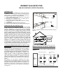
WIZMART GAS DETECTOR
NB-983 SERIES USER’S MANUAL
INTRODUCTION
Wizmart's NB-983-NG and NB-983-LG Series Gas Detector
is effective for detecting any buildup of natural gas and
liquefied gas in your residence. The NB-983 gas detectors
are engineered to perform the following features:
(1) Easy to install. It allows connecting to fire control panel
or security monitoring system.
(2) Monitoring any accidental leaks of natural gas or
liquefied gas in a continuous manner.
(3) Giving a loud alarm (≥ 70 dB) when it detects a buildup
of natural gas.
(4) Self-testing its operative functions continuously.
(5) Offering a 5-year warranty for the natural gas sensing unit.
GASEOUS FUEL IN OUR DAILY LIFE
Either natural gas or liquefied gas has become one of the major
energy sources for our modern life, which has been found its
numerous applications in many sectors such as household,
business, industrial uses and heating systems in the buildings.
At home, we use gas for cooking, drying, heating, and other
purposes. However, any accidental gas leaks into the air may
lead to possible hazards such as fire and explosion, which is
definitely a potential threat to the lose of our lives and household
properties. Most likely sources of leaks come from natural gas
appliances such as heaters, stoves, refrigerators, and furnaces.
Gas leaks from outside or below ground level can also seep into
your home. However, as natural gas builds up, it mixes with
oxygen to produce a mixture that can be combustible and
explosive if it is ignited by a spark or flame. That’s why we
should be more cautious to any accidental leaks of natural gas
or liquefied gas in a continuous manner. The sensor vent port of
the gas detector would allow natural gas to enter the sensor
chamber to be monitored by the sensing circuit built inside.
LOCATIONS WHERE WE NEED TO INSTALL GAS
DETECTORS
Figure 2. Locations for installing gas detectors in your home
WIRING DIAGRAM FOR NB-983 SERIES GAS
DETECTORS
Figure 3 shows the wiring diagram for NB-983 series gas
detectors.
FIRST DETECTOR BASE
LAST DETECTOR
BASE
L
C
FIRE
CONTROL
PANEL
P
POWER
P
2
3
2
3
5
6
5
6
END OF DEVICE
Liquefied gas is heavier than air, the leak of such gas collects
near to the floor or in the lowest levels of rooms. To detect a
dangerous concentration of liquefied gas, you should install
your detector under 30 cm above the floor and less than 4 m
of horizontal distance to the gas appliance in the same room.
Natural gas is lighter than air, therefore, it collects in the
ceiling of rooms. In order to reach effective sensibility of
natural gas leaks, you should install your gas detector as
close to the ceiling as possible, i.e. under 30 cm from the
ceiling and less than 8 m of horizontal distance away from
gas burner or a kitchen stove in the same room, as shown in
Figure 1.
Gas detector can only perform sensitively to the same
location where the gas appliances exist. Since the unusual
gas leaks may occur in other locations in your home, it is
strongly recommended that gas detectors are installed in the
areas where a gas burner or a kitchen stove is used such as
kitchen, living rooms, bed rooms, garage, and basement.
(see Figure 2).
Figure 1. Suggested installation positions for NB-983 series gas
detectors
INSTALLING THE BASE OF DETECTOR
(1)
(2)
(3)
(4)
All the wires in the base compartment should be flattened
and are not touched to any connectors to ensure that the
detector head be smoothly fastened to the base.
When using the jump wires to check the connectivity for
each gas detector in the circuit loop (e.g. connecting point 2
and point 3 with a jump wire as shown in Figure 3), be sure
to remove all the jump wires before attaching the detector
head onto the base.
Be sure that the components used in the circuit loop as
shown in Figure 3 should be coupled up with those
components used in the transceiver circuitry of the control
panel.
The base is allowed to be installed within an available
wiring box including octagon box (3”, 3.5”, or 4”), circular
box (3”) and rectangular box (4” long), without using any
other additional mechanical adapters.
INSTALLING THE DETECTOR HEAD
(1)
Align up the position of head to the base, see Figure 4.
(2) Screw the detector head into the base in clockwise
direction.
(2)
(3)
When the gas leak is detected, green LED light will change
into flashing of red LED light, as accompanying the alarm
sounds.
If the detector is not in normal operation, the buzzer will
sound once every minute to indicate that the malfunction is
detected by the built-in self-monitoring circuitry.
ACTIONS TO BE TAKEN WHEN ALARM OCCURS
We should take the following actions immediately when alarm
occur:
(1) Turn off the valves of gas burners or gas tanks.
(2) Slowly open windows. Do not open windows too fast or the
possible sparking may occur.
(3) Do not use an electrical fan or an air ventilator to disperse
the leaked gas. Instead you can disperse the leaked gas by
stirring a hand fan.
(4) Avoid anything involved with any source that may incur fire
Do not turn on electrical light or strike a match to prevent
any potential explosion.
(5) If any gas leak is found or detected, use duct tape or wet
cloth to wrap the leaking pipes to reduce or stop ongoing
gas leak.
(6) Inform the Gas Company or your gaseous fuel supplier.
You may report to the fire department about the accident as
well.
Specifications
Model
Figure 4 Alignment of detector head and its base
MAINTENANCE OF GAS DETECTORS
A gas detector constantly monitors any gas leaks under its
normal operational conditions. The following maintenance
procedures for gas detectors will assure its desired performance:
(1) Use a vacuum cleaner to clean the dust around the vent
holes of gas detector cover.
(2) Carry out a regular or weekly test of gas detectors.
Gas
Monitored
Operating
Voltage
Min Gas
Level for
Alarming
Alarm
Sounds
NB- Natural Gas
983NG
24 VDC
or
12 VDC
Less
than 1/4
LEL
> 70 dB
with Autoreset
-10oC ~
50oC
2W
NB983LG
24 VDC
or
12 VDC
Less
than 1/4
LEL
> 70 dB
with Autoreset
-10oC ~
50oC
2W
Liquefied
Gas
Operating
Power
Temp. (oC) Consumption
Output
Voltage
With Relay
Output (Dry
connection
output)
With Relay
Output (Dry
connection
output)
WARNING AND LIMITATION
Note that NB-983 series gas detector is not supposed to be used
as smoke detector or fire alarm. In addition, this detector should
not be installed in a “danger area” as defined by National
Electrical Code. A gas detector will operate normally under
regular power supply, therefore, it will not perform at any
situation when power outage occurs.
WARRANTY INFORMATION
Under the normal operation conditions, the manufacturer
provides five-year warranty for the sensor head of gas detector
and one-year warranty for other parts for repairing without
charge. Part and labor charge will be required after the warranty
is expired.
Figure 5 Front cover of detector head
TYPES FOR DETECTOR SIGNALING
The gas detector has to be warmed up for at least 10 minutes
after being energized, then the test procedure can be followed.
There are three types of detector signaling:
(1) Green LED light signal indicates the detector in the normal
monitoring condition.
WIZMART TECHNOLOGY INC.
2F, Building B, #143, Qi-Xin Road, JiangDong Hi-Tech Park, Ning Bo City 315040,
Zhe-Jiang, China