1
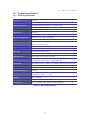
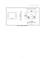
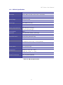
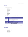
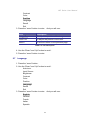
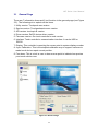
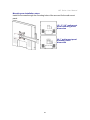
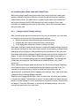
WP Series Wall-mount Panel User Manual Rev 1.0 WP series User Manual Packing List The complete package consist: One wall-mount panel One VGA cable One USB A-A cable (touch screen only) One DVI-D cable (optional) One power cord Driver CD (touch screen only) Check to make sure that the unit was not damaged in shipping. If you encounter a problem, contact your dealer. Please read this manual thoroughly, and follow the installation and operation procedures carefully to prevent any damage to the product, and / or any of the devices that connect to it. I WP series User Manual Safety Instructions 1. Please read these safety instructions carefully. 2. Please keep this User’s Manual for later reference. 3. Please disconnect this equipment from AC outlet before cleaning. Don’t use liquid or sprayed detergent for cleaning. Use moisture sheet or clothe for cleaning. 4. For pluggable equipment, the socked-outlet shall be installed near the equipment and shall be easily accessible. 5. Please keep this equipment from humidity. 6. Lay this equipment on a reliable surface when install. A drop or fall could cause injury. 7. Do not leave this equipment in an environment unconditioned, storage temperature above 600 C, it may damage the equipment. 8. The opening on the enclosure is for air convection hence the equipment from overheating. DO NOT COVER THE OPENING. 9. Make sure the voltage of the power source connect the equipment to the power outlet. 10. Please keep the power cord such a way that people can not step on it. Do not place anything over power cord. The power cord must rate for the voltage and current marked on the product’s electrical ratings label. The voltage and current rating of the cord should be greater than the voltage and the current rating marked on the product. 11. All cautions and warning on the equipment should be noted. 12. If the equipment is not in use for long time, disconnect the equipment from mains to avoid being damaged by transient over-voltage. 13. Never pour any liquid into ventilation openings; this could cause fire or electrical shock. 14. Never open the equipment. For safety reason, qualified service personnel should only open the equipment. 15. If one of the following situations arises, get the equipment checked by service personnel. The Power Cord or plug is damaged. Liquid has penetrated into the equipment. The equipment has been exposed to moisture. The equipment has not worked well or you can not get it work according to User’s Manual. II WP series User Manual The equipment has dropped and damaged. If the equipment has obvious signs or breakage. III WP series User Manual Index of Contents Packing List ......................................................................................................... I Safety Instructions .............................................................................................. II Index of Contents .............................................................................................. IV 1. General Information ..................................................................................... 2 1.1 Overview .............................................................................................. 2 1.2 Product Specification ........................................................................... 3 1.2.1 WP-815 Specification .................................................................. 3 1.2.2 WP-817 Specification .................................................................. 5 1.2.3 WP-919 Specification .................................................................. 7 1.2.4 WP-920 Specification .................................................................. 9 2. Panel Controls and OSD Function ............................................................. 11 2.1 Auto Tune .......................................................................................... 11 2.2 Input Source ...................................................................................... 11 2.3 Brightness .......................................................................................... 12 2.4 Contrast ............................................................................................. 12 2.5 Color .................................................................................................. 13 2.6 Position .............................................................................................. 13 2.7 Language ........................................................................................... 14 2.8 Recall ................................................................................................. 15 2.9 Exit ..................................................................................................... 15 2.10 Power Indicator ................................................................................ 15 3. Touchscreen (option) ................................................................................. 16 3.1 General Page ..................................................................................... 17 3.2 Sound Page ....................................................................................... 18 3.3 Mouse Page ....................................................................................... 19 3.4 Multi-monitor Page ............................................................................. 20 3.5 Advance Page ................................................................................... 21 4. Installation.................................................................................................. 23 4.1 Install Wall-mount Panel .................................................................... 23 4.1.1 Notes ........................................................................................ 23 4.1.2 Installation Steps: ...................................................................... 23 4.2 Installing the Video Card and Video Driver ........................................... 25 4.2.1 Configuring the Display Settings ............................................... 25 4.2.2 Connecting the Wall-mount Panel ........................................... 26 4.3 Turning on the Wall-mount Panel ...................................................... 26 IV WP series User Manual 4.4 Testing the wall-mount Panel ............................................................... 26 V WP Series User Manual 1. General Information 1.1 Overview WP series is designed to provide the industrial user with superior picture quality and state-of-the-art features housed in a rugged industrial enclosure, which will assure reliable operation in most harsh environments. Support Sun native resolution (for 17 / 19 / 20.1” panel) Bright Active Matrix TFT display OSD function (On Screen Display) for LCD display Panel protected by tempered glass Touch screen function 2 WP Series User Manual 1.2 Product Specification 1.2.1 WP-815 Specification Model name WP-815 Dimension 482.6 x 354.6 x 64 mm / 19.0 x 14.0 x 2.5 inches Package Dimension 566 x 484 x 245 mm / 22.3 x 19.1 x 9.6 inches Net Weight 10.5 Kg / 23.1 lbs Gross Weight 14.7 Kg / 32.4 lbs Display Size 15 inches Panel Type Active Matrix TFT LCD Resolution Capabilities Maximum up to 1024 x 768 (XGA) Pixel Pitch Supports 0.297 mm x 0.297 mm Viewing Angle (CR>10) Right-Left View 130°(Typ) Up-Down View 100°(Typ) Contrast Ratio 550:1 Brightness White 250 cd/m² (Center 1 point Typ) Back Light Dual Lamps for Back Light Supported Colors 16M Colors (6-bit with FRC) Response Time Rising Time 2 ms, Decay Time 6 ms Connectors 1 x VGA, 1 x AC Inlet, 1 x Power ON / OFF Switch, 1 x USB or 1 x RS-232(touch screen only), 1 x DVI (optional) Signal Cable VGA cable or DVI-D, USB A-A or RS232 cable (touch screen only) Sync 45 ~ 80 KHz Power Source 100 ~ 240 VAC input Power Consumption 10.12W Temperature Operate 0 ~ 50°C / 32 ~ 122°F Storage -20 ~ 60°C / -4 ~ 140°F Humidity 10% ~ 90% RH Chassis Construction Heavy duty steel materials Touch Screen 5 wires resistive USB interface / RS232 interface Table 1-1. WP-815 Specification 3 WP Series User Manual Figure 1-1. WP-815 Dimension 4 WP Series User Manual 1.2.2 WP-817 Specification Model name WP-817 Dimension 482.6 x 354.6 x 64 mm / 19.0 x 14.0 x 2.5 inches Package Dimension 566 x 484 x 245 mm / 22.3 x 19.1 x 9.6 inches Net Weight 11.0 Kg / 24.3 lbs Gross Weight 15.2 Kg / 33.5 lbs Display Size 17 inches Panel Type Active Matrix TFT LCD Resolution Capabilities Maximum Resolution up to 1280 x 1024 (SXGA) Pixel Pitch Supports 0.264 mm x 0.264 mm Viewing Angle (CR>10) Right-Left view 170°(Typ) Up-Down View 160°(Typ) Contrast Ratio 1000:1 Brightness White 250 cd/m² (Center 1 point Typ) Back Light Dual Lamps for Back Light Supported Colors 16.7M Colors (6-bit with FRC) Response Time Rising Time 3.8 ms, Decay Time 1.2 ms Connectors 1 x VGA, 1 x AC Inlet, 1 x Power ON / OFF Switch, 1 x USB or 1 x RS-232(touch screen only), 1 x DVI (optional) Signal Cable VGA cable or DVI-D, USB A-A or RS232 cable (touch screen only) Sync 45 ~ 80 KHz Power Source 100 ~ 240 VAC input Power Consumption 9.91W Temperature Operate 0 ~ 50°C / 32 ~ 122°F Storage -20 ~ 60°C / -4 ~ 140°F Humidity 10% ~ 90% RH Chassis Construction Heavy duty steel materials Touch Screen 5 wires resistive USB interface / RS232 interface Table 1-2. WP-817 Specification 5 WP Series User Manual Figure 1-2. WP-817 Dimension 6 WP Series User Manual 1.2.3 WP-919 Specification Model name WP-919 Dimension 482.6 x 398.6 x 64 mm / 19.0 x 15.7 x 2.5 inches Package Dimension 561 x 526 x 250 mm / 22.1 x 20.7 x 9.8 inches Net Weight 9.0 Kg / 19.8 lbs Gross Weight 12.0 Kg / 26.4 lbs Display Size 19 inches Panel Type Active Matrix TFT LCD Resolution Capabilities Maximum Resolution up to 1280 x 1024 (SXGA) Pixel Pitch Supports 0.098 mm x 0.294 mm Viewing Angle (CR>10) Right-Left View 170°(Typ) Up-Down View 160°(Typ) Contrast Ratio 1000:1 Brightness White 250 cd/m² (Center 1 point Typ) Back Light Dual Lamps for Back Light Supported Colors 16.7M Colors (6-bit with FRC) Response Time Rising Time 3.6 ms, Decay Time 1.4 ms Connectors 1 x VGA, 1 x AC Inlet, 1 x Power ON / OFF Switch, 1 x USB or 1 x RS-232(touch screen only), 1 x DVI (optional) Signal Cable VGA cable or DVI-D, USB A-A or RS232 cable (touch screen only) Sync 45 ~ 80 KHz Power Source 100 ~ 240 VAC input Power Consumption 11.03W Temperature Operate 0 ~ 50°C / 32 ~ 122°F Storage -20 ~ 60°C / -4 ~ 140°F Humidity 10% ~ 90% RH Chassis Construction Heavy duty steel materials Touch Screen 5 wires resistive USB interface / RS232 interface Table 1-3. WP-919 Specification 7 WP Series User Manual Figure 1-3. WP-919 Dimension 8 WP Series User Manual 1.2.4 WP-920 Specification Model name WP-920 Dimension 482.6 x 398.6 x 64 mm / 19.0 x 15.7 x 2.5 inches Package Dimension 561 x 526 x 250 mm / 22.1 x 20.7 x 9.8 inches Net Weight 10.8 Kg / 23.8 lbs Gross Weight 13.6 Kg / 29.9 lbs Display Size 20.1 inches Panel Type Active Matrix TFT LCD Resolution Capabilities Maximum Resolution up to 1600 x 1200 (UXGA) Pixel Pitch Supports 0.255 mm x 0.255 mm Active Display Area Horizontal: 408.0 mm, Vertical: 306.0 mm Viewing Angle (CR>10) Right-Left view 178°(Typ) Up-Down View 178°(Typ) Contrast Ratio 1000 : 1 Brightness White 300 cd/m² Back Light Six Lamps for Back Light Supported Colors 16.7M Colors (8-bit with FRC) Response Time Rising Time 7 ms, Decay Time 9 ms Connectors 1 x VGA, 1 x AC Inlet, 1 x Power ON / OFF Switch, 1 x USB or 1 x RS-232(touch screen only), 1 x DVI (optional) Signal Cable VGA cable or DVI-D, USB A-A or RS232 cable (touch screen only) Sync 45 ~ 80 KHz Power Source 100 ~ 240 VAC input Power Consumption 45 W Temperature Operate 0 ~ 50°C / 32 ~ 122°F Storage -20 ~ 60°C / -4 ~ 140°F Humidity 10% ~ 90% RH Chassis Construction Heavy duty steel materials Touch Screen 5 wires resistive USB interface / RS232 interface Table 1-4. WP-920 Specification 9 WP Series User Manual Figure 1-4. WP-920 Dimension 10 WP Series User Manual 2. Panel Controls and OSD Function Controls Description Soft power on / off button. Adjacent LED is lit when on. Auto Auto-synchronize and scale down display to any valid factory preset timings. Press to scroll the function you want to adjust. Press to scroll the function you want to adjust. Menu To access the main menu. This button also acts as the “Enter” button. Table 2-1. Panel Controls Figure 2-1. WP Series OSD Control Bar 2.1 Auto Tune Press the “auto tune” button. The panel will adjust the display size automatically and also tune the panel to its best condition. 2.2 Input Source 1. Press the “menu” button. 2. Use the “Down” and “Up” button to scroll. Auto tune. Input Source Brightness Contrast Color Position Language Recall Exit 11 WP Series User Manual 3. Press the“menu”button to enter,and you will see: VGA / DVI 4. Use the “Down” and “Up” button to select the input source of signal. 5. Press the “menu” button to enter 2.3 Brightness 1. Press the “menu” button. 2. Use the “Down” and “Up” button to scroll. Auto tune. Input Source Brightness Contrast Color Position Language Recall Exit 3. Press the“menu”button to enter. 4. Use the“Down”and“Up”button to adjust the brightness of the display. 5. Press the “menu” button to enter. 2.4 Contrast 1. Press the “menu” button. 2. Use the “Down” and “Up” button to scroll. Auto tune. Input Source Brightness Contrast Color Position Language Recall Exit 1. Press the “menu” button to enter. 2. Use the “Down” and “Up” button to adjust the contrast of the display. 12 WP Series User Manual 3. Press the “menu” button to enter. 2.5 Color 1. Press the “menu” button. 2. Use the “Down” and “Up” button to scroll. Auto tune. Input Source Brightness Contrast Color Position Language Recall Exit 3. Press the “menu” button to enter. And you will see: Icon Description 9300°K To set CIE coordinates at 9300°K color 7500°K To set CIE coordinates at 7500°K color 6500°K To set CIE coordinates at 6500°K color User To set user defined CIE Auto color To auto adjust color Return To exit and return to the previous page Table 2-2. Icon Description 4. Use the “Down” and “Up” button to adjust the color of the display. 5. Press “menu” to enter. 2.6 Position 1. Press the “menu” button. 2. Use the “Down” and “Up” button to scroll. Auto tune. Input Source Brightness 13 WP Series User Manual Contrast Color Position Language Recall Exit 3. Press the “menu” button to enter. And you will see: Icon Description Image Pos To adjust the position of the image. OSD Pos To adjust the position of the OSD. Return To exit and return to the previous page Table 2-3. Icon Description 4. Use the “Down” and “Up” button to scroll. 5. Press the “menu” button to enter. 2.7 Language 1. Press the “menu” button. 2. Use the “Down” and “Up” button to scroll. Auto tune. Input Source Brightness Contrast Color Position Language Recall Exit 3. Press the “menu” button to enter. And you will see: English German French Italian Spanish 14 WP Series User Manual 4. Use the “Down” and “Up” button to scroll. 5. Press the “menu” button to enter. 2.8 Recall 1. Press the “menu” button. 2. Use the “Down” and “Up” button to scroll. Auto tune. Input Source Brightness Contrast Color Position Language Recall Exit 3. Press the “menu” button to enter, and you will see: Yes/ No 4. Select “Yes” button then ‘Menu” button to recall the factory setting. Select “No “ to return to the previous page. 2.9 Exit Press the “exit” button to quit OSD menu. 2.10 Power Indicator GREEN RED RED ON STANDBY SUSPEND RED OFF OSD – On Screen Display 15 WP Series User Manual 3. Touchscreen (option) Touch package provides a complete touch control solution including resistive touch panel and optical touch panel. Touch package software is a utility and used for adjusting our touch control devices to optimize our touch solution. Touch package contains 5 function groups (see Figure 3-1). general, sound, mouse, multi-monitor, and Advance. This user guide will explain all of information or parameters in function group order. Figure 3-1. Five Function Groups 16 WP Series User Manual 3.1 General Page There are 7 information items and 2 tool function in the general page (see Figure 3-2). The followings is to explain all the items. 1. Utility version: Touchpack.exe version. 2. Service version: Touchpackservice.exe version. 3. API version: touchapi.dll version. 4. Driver version: Rs232 device driver version. 5. Firmware version: Our touch controller’s code version. 6. Interface: Touch controller’s communication interface. It can be USB or RS232. 7. Display: This controller is reporting the mouse point to system display number. 8. 4 pts. Calibration: This is the simplest calibration way to support customer to made touch device report correct position. 9. Free draw: This is a tool to user to draw mouse point to indicate how precise your touch solution now. Figure 3-2. General Page 17 WP Series User Manual 3.2 Sound Page The sound page supports user to set the items about sound settings (see Figure 3-3). 1. Sound source: There are two sound sources, audio sound and buzzer sound. So, user can choice audio or buzzer radio button. If user selects buzzer mode, user can also adjust the frequency and duration to play the sound you like. The test button can try to play the sound you set. 2. Play sound settings: User can check first pen down to play sound or/and pen up to play sound. If both uncheck, it means that no sound to play. Figure 3-3. Sound Page 18 WP Series User Manual 3.3 Mouse Page The mouse page has four main items, report mode, right click settings, double click settings, touch panel rotation(see Figure 3-4). 1. Report mode item: User can select drawing mode to continue report all points that touch controller senses. Button mode only report two points, first pen down and lift up points. Disable touch will made touch device to not report any point, user must use mouse to return the others to work properly. 2. Right click settings: Our touch solution can generate right click in two ways. I. Auto right click: If you pen down and no move for a while, touch device will generate right click event automatically. II. Manual right click: User launch the “Start manual right click” button and touch solution will show a right click window at the right-bottom corner. If user want to generate a right click, user can hit this window once and then pen down and lift to have a right click. 3. Double click settings: These two parameters, speed and area, are used to change Windows OS parameters about generating double click conditions. The bottom of these two shows the test area and user can click to test the settings to feel your settings best. 4. Touch Panel Rotation: Cooperate with the picture of the display to rotate, touching and accusing of the function needs and then rotating too, very whirling angle is at present:0°(Default)、90°、180°、270°。 19 WP Series User Manual Figure 3-4. Mouse Page 3.4 Multi-monitor Page This page function can be supported on the versions, Windows 2K, XP, and Vista. The multi-monitor page shows the system display distribution in time. It also supports split display to fit some VGA cards. User can right click to pull down the split display type to match your VGA card (see figure 3-5) and then the page will show your settings. User can click display area to show a matching program to link the relation between touch device and display. 20 WP Series User Manual Figure 3-5. Multi-monitor Page 3.5 Advance Page In the advance page (see Figure 3-6), there are three main item functions, Linearization, HID mode, and system tools. 1. Linearization: Some kind of touch sensor, special in 5-wires resistive sensor, need 9 points or 25 points reference points to precisely positioning. User can use the “9 pts linearization” tool or “25 pts linearization” to enhance your touch sensor. 2. HID mode: We support the digitizer HID mode for windows vista. This mode can operate gesture functions provided by windows vista home advance and upper. The mouse HID can work on any windows series versions. So, the touch device is default on the mouse HID mode. 21 WP Series User Manual 3. System tools: The “search Rs232 device” button is used for search our none-plug and play RS232 device. The “system information tool” button will launch user’s installation computer information to provide some information for analysis engineer to trace system problems. The “Download touch par am.” button provides user a tool to gather touch device’s parameters into a file and send to manufacture engineer to analysis when user meet some problems. If manufacture engineer find any wrong, he can fix and save as the other file and send back user. User can use the “Write touch par am.” button to open above file and write into his touch device. Figure 3-6. Advance Page 22 WP Series User Manual 4. Installation 4.1 Install Wall-mount Panel 4.1.1 Notes 1. Before installation, make sure all peripherals and computer have been turned off. 2. Reliable grounding of rack-mounted equipment should be maintained. Particular attention should be given to supply connections other than direct connections to the branch circuit. 4.1.2 Installation Steps: Cabinet installation steps: Install eight screws to mount panel into cabinet. 23 WP Series User Manual Mounting arm installation steps: Install four screws through the mounting holes of the arm and fix the wall-mount panel. 15 / 17 / 19” wall-mount panel mounting holes dimension 20.1” wall-mount panel mounting holes dimension 24 WP Series User Manual 4.2 Installing the Video Card and Video Driver Before connecting the wall-mount panel, make sure your computer has a video card already installed for the panel. After you connect the wall-mount panel, install the video software driver. The video driver is supplied by the video card manufacturer and may be found on the CD-ROM that came with your computer. If you need information on installing a video card or video driver, refer to the manual that came with your video card. 4.2.1 Configuring the Display Settings After connecting the wall-mount panel and turning on your computer, you may need to configure one or more of the following display settings: Display mode (also called desktop area or video resolution) Refresh rate (also called vertical scan rate or vertical sync) Color depth (also called color palette or number of colors) Each video card has several controls that let you adjust the display settings. However, the software and driver for each video card is unique. In most cases, you adjust these settings by using a program or utility provided by the manufacturer of the video card. Most video cards use the Windows Display Properties control panel to configure the display. To open the Windows Display Properties, click the right mouse button in a blank area of the Windows desktop and then select Properties. The Settings tab usually lets you change the Color Palette and the Desktop Area (x by y pixel resolution). Some video cards integrate additional features into the Windows Display Properties control panel to give you an exceptional setup that is flexible and easy to use. For example, the control panel may include an Advanced Properties button, an Adjustment tab, or a Refresh tab for changing other settings. Other video cards have a separate utility for setting display properties. Whenever you change the resolution, color, or refresh rate, the image size, position, or shape may change. This behavior is normal. You can readjust the image using the panel on-screen controls. For more information on the panel on-screen controls, refer to Chapter 2. For more information on configuring the display settings, refer to the manual that came with your video card. 25 WP Series User Manual 4.2.2 Connecting the Wall-mount Panel To connect wall-mount panel to a computer, perform the following steps 1. AC Inlet 2. Power ON/ OFF switch 3. USB port (for touch screen use) 4. VGA port Figure 4-1. Connectors of Wall-mount Panel 1. Turn off your computer. You should always turn off your computer before connecting or disconnecting a device. 2. Connect the video (VGA) connector of the VGA cable to the video card connector on the rear panel of your computer. 3. Connect the USB connector of the USB cable to the USB port on the rear panel of your computer. 4. Connect the AC power cord to the power inlet on the wall-mount and then to a power outlet. 4.3 Turning on the Wall-mount Panel Make sure all cables and the power cord are connected properly. Be sure to tighten all connector screws. Check on / off switch in the back of wall-mount panel is on. The LED underneath of the panel will be green light. 4.4 Testing the wall-mount Panel To test that the wall-mount panel is working properly, perform the following steps: 1. Power up the wall-mount panel, and then turn on your computer. 2. Make sure the video image is centered within the screen area. Use the OSD controls to adjust the image (see note below). 26 WP Series User Manual If the unit does not power on when the on / off switch in the back of wall-mount panel is on, try to push the power on / off button underneath of the panel to power up the unit. You can adjust the horizontal and vertical position, contrast, and brightness to better suit your video card and your personal preference. Refer to Chapter 2 for more information on using the on-screen menu to adjust the video display. Before you begin, make sure that powers to all the devices you will be connecting up have been turned off. To prevent damage to your installation due to ground potential difference, make sure that all the devices on the installation are properly grounded. Consult your direct vendor for any technical issues if necessary. 27