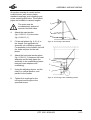
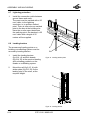
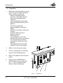
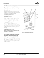
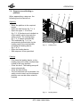
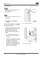
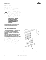
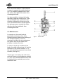
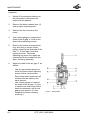
1
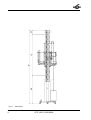
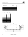
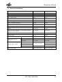
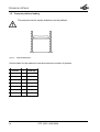
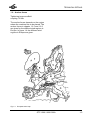
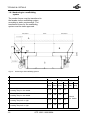
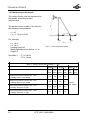
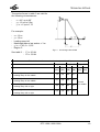
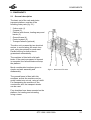
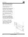
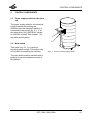
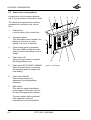
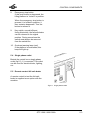
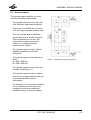
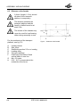
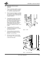
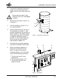
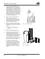
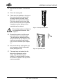
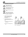
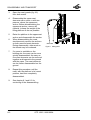
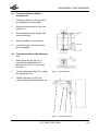
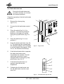
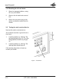
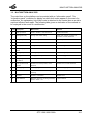
USER’S MANUAL
GTP 1500 TRANSPORT PLATFORM
8095-002A
Issue: 02-98
© 1998, Hek Manufacturing B.V., Middelbeers, The Netherlands
Nothing contained in this publication may be copied and/or published by means of
printing, photocopying, microfilm or any other method, without prior written
permission from Hek Manufacturing B.V.
Drawings are illustrative only and do not necessarily show the design of the product on the market at any
given point of time.
II
GTP 1500 / 8095-002A
HEK GTP 1500 TRANSPORT PLATFORM
Type number
:
Machine number
:
Year of manufacture :
Owner
:
HEK Manufacturing B.V.
Westelbeersedijk 18
P.O. Box 2
5091 SM Middelbeers
5090 AA Middelbeers
The Netherlands
The Netherlands
Tel : +31(0)13 51 48 653
Fax : +31(0)13 51 48 630
GTP 1500 / 8095-002A
III
IV
GTP 1500 / 8095-002A
FOREWORD
FOREWORD
The HEK GTP 1500 is an extremely
compact transport platform for personnel
and material.
This manual describes the installation,
operation and maintenance of the
transport platform.
The mast, consisting of separate
elements, can be adjusted in height to
the height of the building. The mast can
be simply and safely erected, from the
platform.
The transport platform must be anchored.
The HEK GTP 1500 offers a high level of
safety. In the construction of this
transport platform, particular attention
has been paid to all safety requirements.
The drive unit, for example, has been
fitted with an motor brake. An additional
fail safe brake, which operates by
applying a shaft to both racks is fitted.
To simplify transport of the machine to
and on the construction site, the HEK
GTP 1500 can be equipped with
transport wheels.
Thanks to the robust and solid
construction of the transport platform,
only minimum maintenance is required.
This manual describes only the basic
machine, in the standard configuration
supplied by HEK Manufacturing B.V.
Read this manual carefully before using the transport platform.
Take all the safety precautions as described in chapter 3 into account.
GTP 1500 / 8095-002A
V
CONTENTS
CONTENTS
FOREWORD
V
CONTENTS
VI
SURVEY OF ILLUSTRATIONS
VII
LIST OF STANDARDS
7.
OPERATION
7.1 General
7.2 Preparation
7.3 Testing
7.4 Operation from the platform
7.5 Stepover to scaffolding or platform
7.6 Sliding gate
7.7 Operation in an emergency situation
7.8 Fail safe brake
7.9 Static overload device
7-1
7-1
7-2
7-3
7-4
7-5
7-6
7-6
7-8
7-8
8.
DISASSEMBLY AND TRANSPORT
8.1 Transport platform without
transport set
8.2 Transport platform with
transport set
8-1
IX
TECHNICAL DETAILS
1.1 General
1.2 Mast element
1.3 Dimensions GTP 1500
1.4 Electrical installation
1.5 Transport platform loading
1.6 Anchor forces
1.6.1 Anchoring to a scaffolding
system
1.6.2 Anchoring to the facade
1-1
1-1
1-2
1-2
1-3
1-4
1-5
1-6
1-8
2. COMPONENTS
2.1 General description
2.2 Protection at landing height
2-1
2-1
2-2
3. SAFETY
3.1 General
3.2 Safety prior to use
3.3 Safety in use
3.4 Safety after use
3.5 Built-in and additional
safety features
3.6 Personnel
3-1
3-1
3-1
3-1
3-2
3-2
3-3
4.
4-1
5.
ASSEMBLY AND ANCHORING
6-1
6.1 Preparation for assembly
6-2
6.2 Ground support
6-3
6.3 Distance to the facade
6-4
6.4 Assembly of the transport platform 6-5
6.5 Assembly of the mast
6-6
6.6 Anchoring the masts
6-10
6.7 Lightning protection
6-14
6.8 Landing barriers
6-14
VIII
MEANING OF THE SYMBOLS USED
1.
6.
TRANSPORT
4.1 Repositioning on the
construction site
9.
4-2
CONTROL COMPONENTS
5.1 Power supply socket for
the drive unit
5.2 Main switch
5.3 Control box on the platform
5.4 Single phase outlet
5.5 Remote control fail safe brake
8-3
9-1
9-1
9-1
9-4
9-4
9-4
9-5
9-8
9-9
9-10
9-10
5-1
5-1
5-1
5-2
5-3
5-3
10. MALFUNCTION ANALYSIS
10-1
11. MACHINE DISPOSAL
11-1
12. LIST OF KEYWORDS
12-1
1.
VI
MAINTENANCE
9.1 General
9.2 Maintenance intervals
9.3 Motor brake
9.3.1 General
9.3.2 Operating principle
9.3.3 Maintenance
9.4 Fail safe brake
9.4.1 Fail safe brake test
9.4.2 Resetting the
fail safe brake
9.5 Testing the static overload device
8-3
PERIODIC INSPECTION
GTP 1500 / 8095-002A
APPENDICE 1
CONTENTS
SURVEY OF ILLUSTRATIONS
Fig.1-1
Fig.1-2
Fig.1-3
Fig.1-4
Fig.1-5
Fig.1-6
Fig.1-7
Fig.2-1
Fig.2-2
Fig.4-1
Fig.4-2
Fig.5-1
Fig.5-2
Fig.5-3
Fig.6-1
Fig.6-2
Fig.6-3
Fig.6-4
Fig.6-5
Fig.6-6
Fig.6-7
Fig.6-8
Fig.6-9
Fig.6-10
Fig.6-11
Fig.6-12
Fig.6-13
Fig.6-14
Fig.6-15
Fig.7-1
Fig.7-2
Fig.7-3
Fig.7-4
Fig.7-5
Fig.7-6
Fig.7-7
Fig.8-1
Fig.8-2
Fig.8-3
Fig.8-4
Fig.8-5
Fig.9-1
Fig.9-2
Fig.9-3
Fig.9-4
Fig.9-5
Dimensions
X
Dimensions top
1-2
Payload distribution
1-4
European wind map
1-5
Anchoring to the scaffolding system 1-6
Anchoring to the facade
1-8
Anchoring to the facade
1-9
Basic set GTP 1500
2-1
Landing barrier
2-2
Lifting point
4-1
Support points forklift truck
4-1
Drive unit power supply socket
5-1
Control box
5-2
Single phase outlet
5-3
Positioning of the ground support
6-3
Distance to the facade
6-4
Jacks
6-5
Lower striker plate
6-5
Connection to cable drum
6-7
Control box
6-7
Assembly platform
6-8
Mast guard
6-8
Red top mast element
6-9
Top striker plate
6-9
Assembly platform
6-10
Anchoring to the facade
6-13
Anchoring to the scaffolding system6-13
Landing striker plate
6-14
Landing barrier
6-14
Control box
7-2
Push buttons control box
7-4
Loading ramp
7-5
Landing barrier
7-5
Locking sliding gate
7-6
Brake release lever
7-6
Static overload device warning lamp 7-8
Assembly platform
8-1
Mast guard
8-2
Rear wheel set
8-3
Rear cross-brace
8-3
Front wheel set
8-4
Motor brake
9-5
Motor brake
9-6
Plug socket
9-9
Fail safe brake drop test box
9-9
Control box
9-10
GTP 1500 / 8095-002A
VII
LIST OF STANDARDS
LIST OF STANDARDS
The GTP 1500 is a machine as intended in appendix IV of the machine directive, figure
16, built according to the requirements of the EC Directive 89/392/EEC, altered in
Directive 91/368/EEC and 93/44/EEC.
The following standards were also employed in the construction:
draft EN standard 12158-1 Material hoists
draft EN standard 1495 Lifting platforms - mast climbing work platforms
EN standard 60204-1 Electrical equipment of machines
EMV - Directive 89/336/EEC
VIII
GTP 1500 / 8095-002A
SYMBOLS
MEANING OF THE SYMBOLS USED
WARNING
Failing to (exactly) comply with
working or operating
instructions may lead to
serious injury, fatal accident,
severe mechanical damage or
operating losses.
During use, no person may
stand under the machine.
Danger: high voltage.
Danger of falling objects.
GTP 1500 / 8095-002A
IX
Fig.1-1
X
Dimensions
GTP 1500 / 8095-002A
TECHNICAL DETAILS
1.
TECHNICAL DETAILS
Note:
The data in this chapter are based on standard applications for the GTP 1500
transport platform. In special situations, it may be possible to deviate from these
data. This may only be done, however, with prior written approval of the supplier.
1.1 General
See also fig. 1.1.
Description
Fig.1-1 GTP 1500
Platform length [m]
4,0
Platform width [m]
1,5
Height of the platform fence [m]
1,1
Distance between the anchors [m]
C
6-8
Max. mast height freestanding [m]
A
0
Max. mast height anchored [m]
A
120
Max. mast height above last anchor [m]
D
3
Mast type
DRK400
Max. number of persons
7
Platform speed [m/min.]
12
Loading capacity [kg]
1500 kg (see chapter 1.4)
Distance between cable guides [m]
6
Height of the first anchor for ground frame [m]
B
3-4
Min. Platform height [m]
0,40
Noise level
< 70 dB
Weight of basic machine (Incl. 2 Mast elements and 2
top masts [kg]
2095
Transport wheels, type
195/70 R14
Tyre pressure transport wheels [bar]
2
Maximum wind-force during erection
12,5 m/s (6 Beaufort)
Maximum wind-force during use
15,7 m/s (7 Beaufort)
GTP 1500 / 8095-002A
1-1
TECHNICAL DETAILS
1.2 Mast element
Mast element length
1508 mm
Mast element width
400 mm
Mast element depth
315 mm
Modul rack
5
Mast bolts
M14 x 90 Qual. 8.8
Tightening torque
100 Nm
Mast element weight
50 kg
1.3 Dimensions GTP 1500
Fig.1-2, Dimensions [mm]
Fig.1-2
1-2
A
6135
B
4000
C
4700
D
4955
E
1700
F
1530
G
1240
H
1500
Dimensions top
GTP 1500 / 8095-002A
TECHNICAL DETAILS
1.4 Electrical installation
GTP 1500
400V
GTP 1500
Number of motors
2
2
Rated power of work platform
2 x 4,8 kW
2 x 4,8 kW
Max. starting current
110 A
190 A
Power consumption based on
S3-40%
S3-40%
Power consumption
15 kVA
15 kVA
Power consumption at start up
70 kVA
70 kVA
Supply voltage
400 V
230 V
Minim um supply voltage
360 V
205 V
Phases
3 + N + Pe
3 + Pe
Supply frequency (depending on the national conditions
regarding to power supply)
50 or 60 Hz
50 or 60 Hz
Fuse at building site (slow)
32 A
50 A
Control voltage
42 Vac
42 Vac
Control voltage frequency
50 / 60 Hz
50 / 60 Hz
up to 50 m
5 x 6 mm²
4 x 16 mm²
up to 90 m
5 x 10 mm²
4 x 25 mm²
Power supply cable (to
machine)
up to 45 m
230V
4 x 6 mm², 0,51 kg/m
5 x 4 mm², 0,47 kg/m
Machine cable / Weight
up to 85 m
up to 120 m
Single phase outlet
4 x 10 mm², 0,91 kg/m
5 x 6 mm², 0,64 kg/m
4 x 16 mm², 1,27 kg/m
230 V ± 10% / 16 A
230V ± 10% / 16A
GTP 1500 / 8095-002A
1-3
TECHNICAL DETAILS
1.5 Transport platform loading
The payload must be equally distributed on the platform.
Fig.1-3
Payload distribution
See the table for the maximum load and maximum number of persons.
1-4
Persons
+
Load (kg)
1 (min.)
+
1400
2
+
1300
3
+
1200
4
+
1100
5
+
1000
6
+
900
7
+
800
GTP 1500 / 8095-002A
TECHNICAL DETAILS
1.6 Anchor forces
Tightening torque scaffold
coupling: 50 Nm
The anchor forces depends on the region
where the machine has to be placed. The
anchor forces in chapter 1.6.1 and 1.6.2
are given for the different wind regions in
Europe. In figure 1-4 the different wind
regions in Europe are given.
Fig.1-4
European wind map
GTP 1500 / 8095-002A
1-5
TECHNICAL DETAILS
1.6.1Anchoring to a scaffolding
system
The anchor forces must be transferred to
the facade via the scaffolding system,
according to static requirements. The
transferred forces for the scaffolding
system must be static approved.
Fig.1-5
Anchoring to the scaffolding system
Scaffold section length 3,0 m
Region A-C
Region D
F1
(kN)
F2
(kN)
F1
(kN)
F2
(kN)
* Mast height above last anchor = 3m
* Loading ramp in the middle
5,8
3,6
5,8
4,7
* Mast height above last anchor = 0m
* Loading ramp in the middle
4,9
3,6
4,9
4,7
* Mast height above last anchor = 3m
* Loading ramp left or right
6,9
3,6
6,9
4,7
* Mast height above last anchor = 0m
* Loading ramp left or right
5,7
3,6
5,7
4,7
1-6
Region E-G
F1
(kN)
F2
(kN)
Consult
your dealer
GTP 1500 / 8095-002A
TECHNICAL DETAILS
Scaffold section length 2,5 m
Region A-C
Region D
F1
(kN)
F2
(kN)
F1
(kN)
F2
(kN)
* Mast height above last anchor = 3m
* Loading ramp in the middle
7,2
3,6
8,0
4,7
* Mast height above last anchor = 0m
* Loading ramp in the middle
6,1
3,6
8,0
4,7
* Mast height above last anchor = 3m
* Loading ramp left or right
8,3
3,6
8,3
4,7
* Mast height above last anchor = 0m
* Loading ramp left or right
6,9
3,6
8,0
4,7
Region E-G
F1
(kN)
F2
(kN)
Consult
your dealer
GTP 1500 / 8095-002A
1-7
TECHNICAL DETAILS
1.6.2Anchoring to the facade
The anchor forces must be transferred to
the facade, according to static
requirements.
The anchor forces in table 1 are valid for
the following circumstances:
- α = 45°
- x = y = 1,5 up to 2,5m
For example:
-
x = 1,8 m
y = 1,8 m
Loading ramp left
Mastheight above last anchor = 3 m
Region C
Fig.1-6
Anchoring to the facade
See table 1: - F1 = 6,9 kN
- F2 = 3,6 kN
Table 1. Anchor forces to the facade ( α = 45°)
Region A-C
Region D
F1
(kN)
F2
(kN)
F1
(kN)
F2
(kN)
* Mast height above last anchor = 3m
* Loading ramp in the middle
5,8
3,6
5,8
4,7
* Mast height above last anchor = 0m
* Loading ramp in the middle
4,9
3,6
4,9
4,7
* Mast height above last anchor = 3m
* Loading ramp left or right
6,9
3,6
6,9
4,7
* Mast height above last anchor = 0m
* Loading ramp left or right
5,7
3,6
5,7
4,7
1-8
Region E-G
F1
(kN)
F2
(kN)
Consult
your dealer
GTP 1500 / 8095-002A
TECHNICAL DETAILS
The anchor forces in table 2 are valid for
the following circumstances:
-
α = 46° up to 60°
y = 1,5 up to 2,5m
y / x = 1 up to 1,75
For example:
-
x = 1,6 m
y = 1,8 m
Loading ramp left
Mastheight above last anchor = 3 m
y / x = 1,8/1,6 = 1,125
Region C
Fig.1-7
Anchoring to the facade
See table 2: - F1 = 8,3 kN
- F2 = 3,6 kN
Table 2. Anchor forces to the facade ( α = 46° - 60°)
Region A-C
Region D
F1
(kN)
F2
(kN)
F1
(kN)
F2
(kN)
* Mast height above last anchor = 3m
* Loading ramp in the middle
7,2
3,6
8,0
4,7
* Mast height above last anchor = 0m
* Loading ramp in the middle
6,1
3,6
8,0
4,7
* Mast height above last anchor = 3m
* Loading ramp left or right
8,3
3,6
8,3
4,7
* Mast height above last anchor = 0m
* Loading ramp left or right
6,9
3,6
8,0
4,7
Region E-G
F1
(kN)
F2
(kN)
Consult
your dealer
GTP 1500 / 8095-002A
1-9
COMPONENTS
2. COMPONENTS
2.1 General description
The basic set of the rack and pinion
transport platform consists of the
following main parts (fig. 2-1):
* 2 drive units (1)
* 2 masts (2)
* Platform with fences, loading ramp and
barrier (3)
* Ground frame (4)
* Control system (5)
* Transport wheels (optional)
The drive unit, powered by two electrical
motors, is moved along the mast via a
rack, using two pinions for each mast.
Parallel running on both sides is
guaranteed automatically.
The machine is fitted with a fail safe
brake. If the maximum speed of descent
is exceeded, the fail safe brake will stop
the platform.
2
Much consideration has been given to
simple and safe assembly and
disassembly.
Fig.2-1
5
4
3
1
Basic set GTP 1500
The ground frame is fitted with fork
recesses, so that the machine can be
easily loaded onto a truck, using a forklift.
For transporting the machine on the
construction site, the transport wheels
can be used.
Four shackles have been mounted on the
platform, for loading and unloading
using a crane.
GTP 1500 / 8095-002A
2-1
COMPONENTS
During machine assembly and use, the
platform can only be operated when the
barrier is closed and locked in position.
The electrical system is mounted in the
control box on the platform.
All electrical connections, which must be
disconnected for transport purposes, are
being made by means of connectors.
The power supply from the building site
distribution box to the transport platform
is via a supply cable, with 32 A EEC plug.
Thanks to the simple construction
system, maintenance has been kept to a
minimum.
The mast elements, the chassis, the
transport platform, the cable guides and
various other components are protected
from corrosion by means of galvanization
or another appropriate surface treatment.
2.2 Protection at landing height
To protect against the risk of falling at
loading and unloading points on the
scaffold system or facade, landing
barriers must be mounted.
Fig.2-2
2-2
Landing barrier
GTP 1500 / 8095-002A
SAFETY
3. SAFETY
3.3 Safety in use
3.1 General
No changes or modifications
may be made to the machine
The ground surface must be
stable to support the weight of
the machine and the mast.
The mast must ALWAYS be
anchored in accordance with
the instructions.
If during assembly and
disassembly the fences do not
provide sufficient protection,
suitable safety harness must
always be used at heights
above 2 metres.
At wind speeds above 15.7 m/s
(7 Beaufort) the machine must
not be used, and the platform
must be set at the lowest
position.
There must be no obstructions
in the path of the work platform.
During use, no person should
stand under the machine.
Before a mast element or
anchor is installed, or
maintenance work carried out,
the emergency stop button
must be pressed.
Never climb in the mast.
3.2 Safety prior to use
- The transport platform may not be
used freestanding.
- The ground frame must be effectively
supported.
- The working area around the machine
must be free from obstacles.
- Anchors must be mounted at specified
intervals.
- Before use, the switchbox must be
checked if it is locked.
- At wind speeds above 12.5 m/s (6
Beaufort), the machine must not be
assembled/disassembled.
- The wheel set may not remain fitted
during the use, assembly or
disassembly of the machine.
Materials and/or tools must
never extend beyond the outer
limits of the platform. Items
which may roll must be properly
secured. Materials must never
be stacked against the fencing.
If work must be carried out
close to high-voltage cables, a
minimum safety distance of 10
meters must be maintained.
When materials and/or tools
with a large surface area are
used, contact your supplier, in
connection with wind sensitivity.
GTP 1500 / 8095-002A
3-1
SAFETY
When electrical storms are
expected, work on the platform
must be stopped in time to
avoid the danger of lightning
strikes. The power supply must
be switched off and the
connector withdrawn from the
supply socket.
- If the machine is to be used during the
hours of darkness, the area must be
adequately lit, so that the user has a
good view in all conditions. A minimum
brightness of 50 lux at control box
height is required.
- The machine may only be used for the
purpose for which it was designed,
namely the vertical transport of
persons and materials, to a maximum
weight of 1500 kg.
- Loads (materials, persons, etc.) must
be distributed in accordance with the
loading diagram.
- Work on the transport platform may
only be carried out, once the contents
of this user’s manual are known.
- Inspection and maintenance must be
carried out as described in this
instruction manual.
- During assembly and maintenance,
the machine may not be used for other
purposes.
- Local safety laws and regulations must
always be followed.
- Fences must never be removed during
normal use.
- The working area must be kept free
from obstacles (building materials, dirt,
snow, etc.)
3-2
3.4 Safety after use
- Transport on public roads must only be
carried out by a truck intended for that
purpose.
- The transport platform must be placed
in its bottom position and the main
switch must be secured with a padlock
to avoid unauthorised use.
3.5 Built-in and additional safety
features
The machine has been built to offer
maximum safety both during assembly
and use. Therefore, the following built-in
and additional safety features have been
provided:
- electrically monitored mast guard:
when the mast guard is open the
platform is locked;
- emergency stop button on the control
box: when this button is pressed the
platform is locked.
- mechanical safety device for the
barrier on the transport platform;
- buffer to catch the platform, if all limit
switches fail;
- in the event of power failure, the motor
brake on the motor brake drive is
automatically activated;
- in the event of power failure, by
releasing the motor brakes, an
emergency descent can be carried out;
- if the maximum speed during descent
is exceeded, the fail safe brake is
activated;
- if the TOP limit switch fails to operate,
and the transport platform continues to
rise, the TOP emergency limit switch is
activated;
GTP 1500 / 8095-002A
SAFETY
- if the LOWER limit switch fails to
operate, and the transport platform
continues to descend, the LOWER
emergency limit switch is activated;
- if the TOP limit switch fails, and the red
top mast has not been fitted, so that
the transport platform continues to
rise, the drive unit will be caught on the
safety hooks;
- parallel running safety device. Parallel
running is guaranteed via a connection
shaft with two pinions, which interlock
with the rack;
- audiovisual warning system: When the
transport platform descends it will stop
for 3 seconds at 2,5 m above the
ground., an intermittent buzzer
sounds, and a light flashes on the
underside of the platform. After 3 sec.
the platform descends further, the
buzzer stops and the light goes out.
- electrical monitoring of load gates:
when the gate is open the platform is
locked;
- electrical monitoring of loading ramp:
when the ramp is open the platform is
locked;
- static overload device: locks the
platform when it is overloaded.
3.6 Personnel
The transport platform may only be
assembled, disassembled and controlled
by persons who:
- are over the age of 18 years;
- are instructed about the
assembly and disassembly of the
transport platform;
- are authorized by the owner to
assemble, disassemble, control
and maintain the machine. The
authorisation must be on paper;
- are familiar with the emergency
instructions and the contents of
this user’s manual are known.
- The technical personnel must be in a
position to deal with any difficulty
encountered, during assembly and
disassembly.
- The operating personnel must be
familiar with all situations which can
occur during use.
- If operating or technical personnel note
any faults or dangers, or are not in
agreement with the safety measures
taken, the owner or person responsible
must be immediately informed.
- Work on the electrical systems may
only be carried out by a qualified
electrician.
- Personal protective equipment such as
hard hat, safety shoes and close-fitting
clothing must be used.
- When entrusting the platform to a third
party, an introduction must be carried
out, according to the transfer protocol,
and fully naming the machine operator.
GTP 1500 / 8095-002A
3-3
TRANSPORT
4.
TRANSPORT
The machine may not be
transported on the public road,
on the transport wheels.
All nationally valid traffic
regulations must be observed.
During transport, no load must
be present on the platform.
Check that both ground units
are locked in position.
The basic unit of the machine has been
dimensioned in such a way that it can be
transported on a standard truck. Ensure
that, during transport, all securing devices
are properly fitted and the machine is
lowered onto the buffers.
Before transporting, disassemble the
machine as described in chapter 8.
Before transportation, all additionally
mounted mast elements and connection
cables must be disassembled, and the
jacks withdrawn.
The machine can be loaded and
unloaded from the transport vehicle using
a crane mounted on the vehicle, a crane
on the building site or a forklift truck. See
figure 4-1/4-2 for the loading and
unloading points.
Fig.4-1: Lifting point for lifting sling
Fig.4-2: Support points for forklift truck
fork
Set the machine down carefully to avoid
damage.
For transport dimensions, see chapter 1.
For transportation, the machine must be
tightly lashed down onto the truck flat
bed.
Fig.4-1
Fig.4-2
Lifting point
Support points forklift truck
GTP 1500 / 8095-002A
4-1
TRANSPORT
4.1 Repositioning on the
construction site
Before repositioning the
platform, ensure that no trees,
power lines, etc. can
be affected.
During repositioning, there may
be no load or persons on the
platform.
The wheel set may not remain
fitted during the use, assembly
or disassembly of the machine.
On the construction site, the transport
platform can be moved, in its lowest
position, using the (optional) transport
set, consisting of two side wheels, a front
wheel and a tow bar.
On smooth, solid and level ground, the
mast may be transported, with a
maximum mast height of 3 meters.
In less favourable conditions, contact the
supplier. The transport set can be
attached to a vehicle, and towed. The
maximum speed during repositioning
using another vehicle is 30 m/min.
4-2
GTP 1500 / 8095-002A
CONTROL COMPONENTS
5.
CONTROL COMPONENTS
5.1 Power supply socket for the drive
unit
The power supply cable for the electrical
supply between the building site
distributor and the transport platform is
connected to the socket (fig. 5-1, 1) on
the cable drum (32 A EEC/400V socket
or 63A/230V socket). See chapter 1 for
the cable specifications.
1
2
5.2 Main switch
This switch (fig. 5-1, 2) is used for
activating power supply. This switch may
not be used for stopping the machine.
Fig.5-1
Drive unit power supply socket
The main switch shall be secured with a
padlock to prevent unauthorized use of
the platform.
GTP 1500 / 8095-002A
5-1
CONTROL COMPONENTS
5.3 Control box on the platform
A control box for the transport platform
(fig. 5-2) is mounted on the platform itself.
1
2
3
4
5
6
The following components for machine
operation are mounted on the control
box:
1.
Cabinet lock
Locks the door of the control box.
2.
Information panel
This information panel consists of a
display on which error codes
appear, if an error is detected.
3.
Control lamp (green) (operation)
This lamp lights up when the main
switch is on and the safety circuit is
closed.
4.
Push button UP
When this push button is pressed,
the lifting platform rises.
5.
Push button STOP NEXT LANDING
When this push button is pressed,
the transport platform stops at the
next landing.
6.
Push button DOWN
When this push button is
depressed, the lifting platform
descends.
7.
Main switch
This switch is used for activating
power supply. This switch may not
be used for stopping the machine.
10
Fig.5-2
Control box
The main switch shall be secured
with a padlock to prevent
unauthorized use of the platform.
5-2
9
GTP 1500 / 8095-002A
8
7
CONTROL COMPONENTS
8.
Emergency stop button
If this push button is depressed, the
lifting platform is “locked” in position.
When the emergency stop button is
pressed, it is locked in position; it
then remains depressed. Turn the
button to release it.
9.
Key switch, normal/off/reset
Using this switch, the fail safe brake
can be returned to its original
position. During normal use the
switch must always be removed
from the switch box.
10. Overload warning lamp (red)
If the platform is overloaded, this
lamp will light up.
5.4 Single phase outlet
Beside the control box a single phase
outlet (fig.5-3, 1) is mounted. This outlet
can be used for electrical tools, lighting,
etc.
5.5 Remote control fail safe brake
A remote control to test the fail safe
brake is supplied as an option with the
machine.
1
Fig.5-3
Single phase outlet
GTP 1500 / 8095-002A
5-3
ASSEMBLY AND ANCHORING
6.
ASSEMBLY AND ANCHORING
This chapter describes the assembling and anchoring of the transport platform.
If assembly work must be interrupted, it must be done in such a way that
when the work is restarted, it is clear what stage had been reached when work
was stopped. For this reason, always complete a part of the assembly (for
example connect, tighten or secure all components for a connection, complete
a ground support or completely assemble an anchor) before interrupting
assembly.
Whilst the mast is being erected, no more than 2 persons may be on the GTP
1500 transport platform, so that no more than 50% of the lifting capacity is
used.
The loading of the transport platform must be planned so that when, during
assembly, the maximum mast height is reached above the last anchor (max.
distance between anchors is reached), the material load on the platform is at
a minimum.
Assembly must always be followed by a test run, as described in section 7.3.
Until the test has been performed, the platform may not be used for any
purpose other than transporting its own mast elements and anchoring
components.
GTP 1500 / 8095-002
6-1
ASSEMBLY AND ANCHORING
6.1 Preparation for assembly
Ensure that the site where the
transport platform is to be
assembled meets the locally
applicable safety requirements,
and that permission for the
assembly has been obtained
from the relevant authorities.
- Ensure that a suitable power supply,
good lighting, lifting equipment and
tools are available.
- Ensure that the building site is easily
accessible to the vehicle which will
deliver the transport platform.
- Prepare the site with suitable support
and anchoring facilities.
- Ensure that the position where the
transport platform is to be built has
good drainage.
- Plan the positioning of the transport
platform against a facade in such a
way that where anchoring is required,
it can be carried out using standard
equipment.
- The components of the transport
platform should be placed as close as
possible to the transport platform
assembly site.
- The electrical power supply connection
for the transport platform must be
placed as close as possible to the
transport platform, to reduce voltage
drop. In the event of excessive voltage
drop, the machine may not function
correctly.
6-2
GTP 1500 / 8095-002
ASSEMBLY AND ANCHORING
6.2 Ground support
The ground support and the soil must
meet the following requirements:
B
- The ground surface must be flat, and
offer sufficient load-bearing capacity.
- Ensure an even distribution of forces,
over the largest possible surface area.
A
- The soil must be able to withstand
ground pressure of at least 2 kg/cm2.
If this requirement is not met, soil
improvement measures must be
carried out, until this minimum
requirement is fulfilled.
- The ground support must be able to
withstand a pressure of at least
20 kg/cm2.
- The ground support must measure at
least :
A = 600 x 600 mm
B = 350 x 600 mm
B
Fig.6-1
Positioning of the ground support
- The ground support must be flat, and
centrally loaded (fig. 6-1).
- The ground support must be durable,
and of such a quality that the load can
be transferred without plastic
deformation.
- For assembly on a concrete foundation
or on a hardened road surface, the
installation must be provided with
wooden packing, to prevent slipping.
GTP 1500 / 8095-002
6-3
ASSEMBLY AND ANCHORING
6.3 Distance to the facade
A fence (height 1.10 m) around
all sides of the transport
platform is compulsory.
The distance between the
transport platform and the
facade / scaffold must be at
least 0,5m
The wheels of the chassis may
never be used for load bearing,
either during assembly or use.
For the positioning of the transport
platform, see fig. 6-2.
A.
B.
C.
D.
E.
F.
G.
H.
6-4
Fig.6-2
Distance to the facade
Landing barrier
Side fence
Scaffolding section 2.5 m or landing
Loading ramp
Transport platform
Positioning line Barrier B and
vertical frame in one line
Min. 0,5 metre
0,65 - 0,67 m measured at the
underside of the fence.
GTP 1500 / 8095-002
ASSEMBLY AND ANCHORING
6.4 Assembly of the transport
platform
1.
Place the transport platform parallel
to the facade, as shown in chapter
6.3, and level using a spirit level.
2.
Place the ground support in position
(see section 6.2 for details) beneath
the transport platform and lower the
transport platform.
3.
Check that the masts are vertical,
and that the transport platform is
horizontal to the ground support. If
not, correct the ground support.
Measurement must be carried out
on two sides of the mast, with a
spirit level measuring at least 1 m in
length.
4.
The jacks (fig. 6-3, A) must be
released simultaneously, to cancel
any bearing function.
5.
Check whether the lower striker
plate (fig. 6-4) is fitted in the right
position. If not, fit it now.
6.
Pull the rail of the 2.5 metre stop
fully outwards. The rail is mounted
in the left lower mast.
A
Fig.6-3
Jacks
Fig.6-4
Lower striker plate
GTP 1500 / 8095-002
6-5
ASSEMBLY AND ANCHORING
6.5 Assembly of the mast
If work has to be stopped,
always complete the phase
being worked on. Tighten all the
bolts used for the last
attachment, and switch off and
secure the main switch, so that
the machine cannot be
operated.
As the assembly proceeds, the
anchor tubes, anchors and
cable guides must be installed,
as described in chapter 6.6.
Ensure that the power supply of
the building site is
corresponding with the electric
design of the machine.
The mast(s) must always be
assembled vertically.
At winds speeds above
12.5 m/s (6 Beaufort), the
machine may not be
assembled.
While a mast element is being
mounted, the emergency stop
must be active.
During the erection phase the
assembly platform can be used.
When the small assembly
platform cannot be used during
erection, the seperate assembly
platform (option) should be
used.
6-6
GTP 1500 / 8095-002
ASSEMBLY AND ANCHORING
1.
Connect the machine to the power
supply, by connecting the power
supply socket to the cable drum (fig.
6.5).
Ensure that the cable is fully
rolled off, and in an undamaged
condition.
2.
3.
4.
5.
6.
Switch the main switch (fig.6-5, 2)
in position 1.
Turn the switch key (fig.6-6, C) in
the normal position.
Set the main switch (fig. 6-6, A) on
the switchbox to position “1” (the
position depends on the direction of
phase rotation of the power supply).
If the green lamp (fig. 6-6, B) does
not light up, place the switch in
position “2”. If the green lamp still
does not light up, see the fault
tracing table in chapter 10.
1
2
Fig.6-5
Check that the proximity switches
have been mounted on both sides.
Connection to cable drum
C
B
A
When the transport platform is
delivered it is lowered into the
buffer. In order to remove the
transport platform out of the buffer,
carry out the following procedure:
1 Turn the key switch “reset
positioning”.
2 Press the push-button “UP”.
3 Turn the key switch in the
position normal.
Fig.6-6
Control box
GTP 1500 / 8095-002
6-7
ASSEMBLY AND ANCHORING
7.
Raise the transport platform by
approximately 50 cm, by pressing
the UP button. Once again lower the
transport platform, by pressing the
DOWN button. In this way, you can
test the operation of the bottom limit
switch. In addition, an emergency
stop push button is provided. When
this button is pressed, the power of
the motors will be shut off.
8.
Place (using a forklift truck or a
crane) mast elements and
anchoring material on the platform.
Take note of the maximum load
permitted during assembly.
9.
Open the assembly platform gate
and affix into position using the bolt
(fig.6-7).
Fig.6-7
Assembly platform
Fig.6-8
Mast guard
A. Position of the gate during
erection.
10. Open the mast guard (fig. 6-8).
11.
Attach the first mast element left
and right with 4 bolts, spring
washers and nuts. When there is no
crane available the mast elements
must be placed by two persons.
Tighten with a torque wrench to the
specified torque (see chapter 1).
If a crane is available on the
construction site, the mast can be
assembled more rapidly. In this
case, four mast elements can be
assembled on the ground and
positioned on the mast, using the
crane.
6-8
GTP 1500 / 8095-002
ASSEMBLY AND ANCHORING
12. Mount the first anchor. See section
6.6.
13. Close the mast guard.
14. Then raise the platform to the top of
the mast element and repeat this
working method until new mast
elements are required from below.
Plan your work in such a way that
when an anchor has to be installed
(maximum anchor distance), the
material load is minimal.
Ensure that anchors are fitted at
the prescribed distances. See
chapter 1.
Fig.6-9
Red top mast element
15. Repeat this method until the mast
has reached the required height.
The last element assembled must
always be the red top element. The
maximum permitted mast height
may not be exceeded (see chapter
1).
16. Mount the red top striker plate (top
and emergency stop) to the mast
ends (see figure 6-9)
Fig.6-10 Top striker plate
17. The mast may not extend too far
above the uppermost anchor
(max. 3m). To achieve good
stability, it is always better to place
an anchor as close to the top of the
mast as possible.
GTP 1500 / 8095-002
6-9
ASSEMBLY AND ANCHORING
18. On construction sites where there is
a risk that people may walk through
the path of the platform, the entire
machine must be secured with
safety fencing.
19. Close the assembly platform gate
and affix into position using the bolt
(fig.6-11).
B. Position of the gate during use.
20. Assembly is now complete, and a
test run must be carried out, as
described in chapter 7.2 & 7.3. Also
a fail safe brake test must be
carried out.
Fig.6-11 Assembly platform
6.6 Anchoring the masts
If work must be stopped, always
complete the current phase
before stopping. Tighten all the
bolts for the latest fixture and
secure the main switch so that
the transport platform cannot be
operated.
The loading of the transport
platform must be planned in
such a way that the material
load on the platform is minimal,
when during mast assembly, the
maximum mast height above
the last anchor (maximum
anchor distance) has been
reached.
6-10
GTP 1500 / 8095-002
ASSEMBLY AND ANCHORING
The facade must be capable of
absorbing all occurring anchor
forces (see section 1.6). These
anchor forces must be
approved by the owner/person
responsible for the building to
which the anchor is to be
attached.
In the event of anchoring
against a scaffold system, this
approach must be agreed with
the scaffold builder and a static
confirmation is required.
Before starting anchoring work,
check once again, using a spirit
level with a length of at least 1
meter, that the mast is actually
vertical (see also section 6.4).
Repeat this process at every
anchor.
While an anchor is being
mounted, the emergency stop
must be active.
Anchors may be attached either to the
scaffolding system or the facade.
Scaffold:
the anchor forces must be transferred to
the facade via the scaffolding system,
according to static requirements.
Facade:
the anchor forces must be transferred to
the facade, according to static
requirements.
GTP 1500 / 8095-002
6-11
ASSEMBLY AND ANCHORING
1.
Check that the mast is vertical with
a spirit level at least one metre long.
Recheck as each anchor is secured.
2.
The mast must be anchored to the
building at the distances specified in
the table in section 1.1.
3.
Fixing the anchors:
- Anchors must be carried out
using bolt couplings, nut and bolt
fastenings and washers. If
conditions make it necessary, use
may be made of other approved
attachment materials, suitable for
the forces occurring. (Consult
your dealer.)
- Cemented-in anchors must be
fitted before assembly of the
transport platform, to give the
cement enough time to dry. The
cement or concrete used must
meet the specifications.
- If chemical anchors or expansion
bolts are used, these must be
tested, and capable of
withstanding the forces involved.
- Specifications for these types of
bolt are available from the
supplier. Permission to use these
connection types must be
obtained from the local
authorities.
6-12
GTP 1500 / 8095-002
ASSEMBLY AND ANCHORING
An anchor consists of a mast anchor,
scaffold tubes, wall anchor plates,
standard couplings, twist couplings and
screw couplings with bolts. The scaffold
pipes are available in various lengths.
The mast must be
simultaneously anchored
mounted on both sides.
4.
Attach the mast anchor
(fig. 6-12/6-13, 2) to the mast
(fig. 6-12/6-13, 1).
5.
Fit the wall plates (fig. 6-12, 4) to
the facade (not applicable for
assembly on scaffolding system).
For assembly to the facade, first drill
the holes required for the wall
plates.
6.
Attach the horizontal anchor pipes
(fig. 6-12/6-13, 3) between the mast
adapters and the wall plates (for
assembly to the scaffolding system:
between mast adapters and
scaffolding).
7.
Using the adjusting device, set the
mast in a vertical position, and
parallel to the facade.
8.
Tighten the couplings for the
horizontal anchor pipe to the
specified torque.
1
2
3
4
Fig.6-12 Anchoring to the facade
3
2
1
Fig.6-13 Anchoring to the scaffolding system
GTP 1500 / 8095-002
6-13
ASSEMBLY AND ANCHORING
6.7 Lightning protection
1.
Install the connection cable between
ground frame and earth.
The mast must be earthed with a 25
mm² cable, to the lightning
conductor, or to another earthed
point. There is often also an earthed
point in the box at the building site.
Have the on-site expert determine
the earthing point. As standard, a 25
mm² cable with a length of 25
metres will be supplied.
6.8 Landing barriers
The access and loading points on a
building or scaffolding system must be
secured by landing barriers.
1.
2.
Install the landing barriers
(fig.6-14, A) and kick boards
(fig.6-14, B) at the required loading
and unloading positions on the
facade or scaffolding system.
A
B
Fig.6-14 Landing striker plate
Mount the rail (fig.6-15, A) with
striker plate (fig.6-15, B) for the
landing stop in the mast, at the
required height.
B
A
Fig.6-15 Landing barrier
6-14
GTP 1500 / 8095-002
OPERATION
7.
OPERATION
7.1 General
No person may stand under the
machine whilst it is in use.
The load may never extend
beyond the edge of the
platform. Items which can
roll must be properly secured.
The load must never be
supported against the
fencing.
The maximum reaction force
(for instance caused by tools) of
the platform, in respect of the
facade may not exceed 400 N.
When work stops or is
interrupted, and when leaving
the construction site, the main
switch must be secured with a
padlock.
GTP 1500 / 8095-002A
7-1
OPERATION
7.2 Preparation
1.
Before the transport platform can be
used, it must be visually inspected
(daily if used every day) for:
- anchors and cable guides
- presence of all safety devices
- connections between mast
elements
- vertical assembly of the masts,
and horizontal positioning of the
platform
- any loose components
- ground supports and ground
quality
- electrical connections (cable and
voltage)
- presence and securing of
protective devices
- safety aspects
- correct operation of the limit
switches (top, bottom, emergency
top, and emergency bottom)
- no obstacles in the path of the
platform
- oil leaking from the drive units
- operation of the motor brakes
2.
Switch on the site power supply.
3.
Close the sliding gate, the loading
ramp and the landing barriers.
4.
Remove the padlock from the main
switch.
5.
Check that the EMERGENCY
STOP buttons on the control box
(fig. 7-1, B) is switched off (the
buttons must be withdrawn).
A
Fig.7-1
7-2
B
Control box
GTP 1500 / 8095-002A
C
OPERATION
6.
Switch the key switch in the Normal
position.
7.
Switch the main switch (fig. 7-1, C)
to position “1” or “2”. The green
warning lamp “operation” (fig. 7-1,
A) on the control box should light
up.
7.3 Testing
1.
Now test the platform and perform
all the inspections as described in
appendix 1.
GTP 1500 / 8095-002A
7-3
OPERATION
7.4 Operation from the platform
The machine may only be operated by a
qualified person.
A
B
C
UP (fig.7-2, A):
When this push button is pressed, the
platform is raised. When the push button
is released, the platform stops
immediately (hold to run).
DOWN (fig.7-2, C):
When this push button is pressed, the
platform is lowered. When the push
button is released, the platform stops
immediately (hold to run).
LANDING (fig.7-2, B):
When the UP or DOWN button is
pressed, followed by the landing button,
the platform rises or descents to the next
landing. This button shall only pressed
shortly.
EMERGENCY (fig.7-2, D):
When this push button is pressed, the
machine is switched off.
D
Fig.7-2
Push buttons control box
The machine is fitted with a 2.5 m stop;
this means that during lowering, the
platform stops at a height of 2.5 m for
approx. 3 seconds. During these 3
seconds, a warning signal tone is heard.
The DOWN push button must once again
be pressed, to permit the platform to be
further lowered.
7-4
GTP 1500 / 8095-002A
OPERATION
7.5 Stepover to scaffolding or
platform
1
2
3
1
When approaching a stepover, the
following must be carried out.
Opening:
- Raise the platform to the required
height.
- Open the side fences (fig. 7-3, 1).
- Open the upper 1.10 m-lever
(fig. 7-3, 2) (further travel is halted via
a limit switch, which interrupts the
safety circuit). The loading ramp
(fig. 7-3, 3) opens automatically.
- The footboard (fig. 7-4, 2) is
automatically pushed down by the
loading ramp, thus mechanically
releasing the landing barrier
(fig. 7-4, 1).
- Open the landing barrier.
- Safe stepover is now permitted.
Fig.7-3
Loading ramp
Closing:
1
2
- First close the landing barrier, or the
loading ramp will remain mechanically
locked in the open position.
- Close the lever. The loading ramp will
close automatically.
- Close the side fences.
- The limit switches will be released, the
safety circuit closed, and the transport
platform can now be either raised or
lowered.
Fig.7-4
Landing barrier
GTP 1500 / 8095-002A
7-5
OPERATION
7.6 Sliding gate
A
Opening:
- Release the locking mechanism of the
gate upwards (fig.7-5, A).
- Open the gate.
Closing:
- Close the gate. The gate will be locked
automatically.
7.7 Operation in an emergency
situation
In an emergency situation, for example in
the event of a power failure, the platform
can always be lowered.
Fig.7-5
Locking sliding gate
Fig.7-6
Brake release lever
- Using the fault-tracing table in chapter
10, attempt to solve the problem. If the
problem cannot be solved, it is
possible to make an emergency
descent to the next landing down, as
follows:
1.
On each motor, there is a lever
which permits the motor brake to be
released.
2.
If this lever is operated, the platform
will descend. The brake lever must
be operated by two persons,
according to an agreed clear
system. It is, however, possible for
one person to “carefully” operate the
motors to lower the platform by
approx. 5 cm on each side.
7-6
GTP 1500 / 8095-002A
OPERATION
The lowering speed must not
exceed the lowering speed
during normal operation. If
lowering speed is too high, the
fail safe brake will be activated.
After a maximum descent of 5
meters, stop the platform for at
least 2 minutes, in order to
prevent overheating of the
brakes, which will result in less
efficient operation.
3.
Due to a connection shaft between
the masts, the platform cannot
become inclined. The machine can,
however, recognise an “overload”
situation. If a motor brake is
released, the entire load is shifted to
the other motor. This motor then
registers an overload. This overload
can be equalized, if the load-bearing
motor is slightly released, until both
motors once again take up the load.
GTP 1500 / 8095-002A
7-7
OPERATION
7.8 Fail safe brake
When the allowable descending speed of
the platform is exceeded, the fail safe
brake will stop the platform.
Whenever the fail safe brake
has been operated, the origin
of the fault must first be
determined. The fault must
first be corrected before the
fail safe brake may be
returned to its normal
position. In event of
uncertainty the service
organisation must be
informed.
For returning the fail safe brake in its
original position, see section 9.4.
7.9 Static overload device
The transport platform is equipped with
an overload safety device, which
measures the static overload of the
platform.
If the load on the platform exceeds the
permitted maximum load, the static
overload device is activated. If the static
overload device is active, the red warning
lamp (fig. 7-7, A) on the platform
illuminates, and a signal tone is sounded.
The machine cannot be operated. To
correct this situation, part of the load
must be removed from the platform.
A
Fig.7-7
7-8
Static overload device warning lamp
GTP 1500 / 8095-002A
DISASSEMBLY AND TRANSPORT
8.
DISASSEMBLY AND TRANSPORT
Ensure that the maximum
loading allowed during
assembly is not exceeded.
At wind speeds above 12.5 m/s
(6 Beaufort) the machine may
not be disassembled.
Never remove any intermediate
anchor.
Never remove an uppermost
anchor unless the mast above
the anchor is disassembled and
the platform is unloaded.
1.
Check all connections, safety
devices, switches and safety
measures. Record any
discrepancies.
2.
During the disassembly the
assembly platform (fig.8-1) can be
used.
A. Position of the railings during
disassembly.
B. Position of the railings during
use.
Fig.8-1
Assembly platform
GTP 1500 / 8095-002A
8-1
DISASSEMBLY AND TRANSPORT
3.
Open the mast guards (fig. 8-2)
from both masts.
4.
Disassemble the upper mast
elements with a crane or with two
persons, above the uppermost
anchor. Before disassembling the
uppermost anchor, remove all
material, to keep the weight of the
lifting platform as low as possible.
5.
Raise the platform to the uppermost
anchor and disassemble the anchor.
When disassembling the mast,
simultaneously remove the anchors
on both removed mast elements.
During disassembly, other work on
the facade may be continued.
6.
7.
If a crane is available on the
building site, the mast can be more
quickly disassembled. As many as
four mast elements can be removed
together and lowered to the ground
with the crane. The mast elements
can be further disassembled on the
ground.
8.
Repeat this procedure until the
mast, with the platform in its lowest
position, has been completely
disassembled.
9.
See chapter 8.1 and 8.2 for
continuing of the disassembling.
8-2
Fig.8-2
Mast guard
GTP 1500 / 8095-002A
DISASSEMBLY AND TRANSPORT
8.1 Transport platform without
transport set
1.
Lower the platform onto the buffer,
by releasing the motor brake.
2.
Switch the main switch to the zero
position “0”.
3.
Disconnect the power supply, and
remove the plug.
4.
Store all cables in a safe place.
5.
Lower the jacks, and remove the
ground support.
1
2
1
8.2 Transport platform with transport
set
1.
Slide the wheel set (fig.8-3,1)
beneath the underside of the
platform (fig.8-3,2) on the control
box side.
2.
Fit the cross-brace (fig.8-4,1) using
the bolts (fig.8-4,2).
3.
Tighten the bolts (fig.8-4,3) to
remove the play from the wheel set.
Fig.8-3
2
Fig.8-4
Rear wheel set
1
3
2
Rear cross-brace
GTP 1500 / 8095-002A
8-3
DISASSEMBLY AND TRANSPORT
4.
Slide the wheel set for the steering
side (fig.8-5,1) into the front of the
platform (fig.8-5,2) and lock it onto
the underside of the platform using
locking pins (fig.8-5,3).
5.
Grease the grease nipple on the
turning point of the front wheels (if
necessary).
6.
Fit and lock the tow bar (fig.8-5,4).
7.
Check the tyre pressures.
8.
Operate the ”down” button until the
machine is switched off by the limit
switch.
9.
The ground frame can be pulled up
in the following manner:
A. Turn the key switch to the “call
back” position.
B. Press the “down” button. The
machine will switched off by the
lower emergency switch.
C. Turn the key switch to the “0”
position.
4
Fig.8-5
1
Front wheel set
10. Switch the main switch to the zero
position “0”.
11.
Disconnect the power supply, and
remove the plug.
12. Store all cables in a safe place.
8-4
GTP 1500 / 8095-002A
3
2
MAINTENANCE
9.
MAINTENANCE
9.1 General
The simple, robust construction of the machine ensures that maintenance can be kept
to a minimum. Sensible use of the machine, regular checks for correct functioning and
regular cleaning will result in a minimum requirement for maintenance. This will
guarantee a long working life for the machine.
Maintenance on the transport platform may only be carried out by persons
with adequate knowledge and qualifications to do so. Preferably by qualified
persons from the manufacturer or the dealer.
Spare parts must comply with the technical specifications of HEK Manufacturing
B.V. Use only original parts from HEK Manufacturing B.V.
Before maintenance is carried out:
- Switch off the main switch. The main switch shall be secured with a padlock
(The main switch having been switched off, there still remains voltage on
).
the parts marked with
- remove the power supply socket
- lower the platform onto the buffers.
- When maintenance work is being carried out under the platform, the platform
must be mechanically blocked.
9.2 Maintenance intervals
The following maintenance activities are essential:
Daily maintenance
Daily maintenance is described in chapter 7.2.
GTP 1500 / 8095-002A
9-1
MAINTENANCE
A.
Weekly maintenance
- Carry out the work described in the chapter “daily maintenance”.
- Grease the rack and pinion. If these are heavily contaminated with sand or grit, they
must first be cleaned.
Grease lubricant specification:
- HEK rack and pinion grease
- Shell Rhodina 2
- Clean the transport platform and the drive unit. Pay particular attention to any
encrustation of the motor cooling fins.
- Visually check the rack and pinion (pitting).
The rack and pinion should be lubricated more regularly, if the transport
platform is subject to intensive use.
B.
Monthly maintenance
- First carry out all work described in A.
- Check the guide rolls and guides (visible inspection of security devices, gaskets and
bearings).
- Check that all mast bolts are still in place, and tighten to the specified torque
(use a torque wrench).
- Check that all bolts are still in position, and thoroughly tightened.
- Check all locking bars and hinges.
- Check all mast anchors and re-secure any loose parts.
- Lubricate the jacks and if fitted, the steering knuckle of the transport wheel.
- Check the operation of all limit switches.
- Check the oil level in the reduction gear unit. If necessary, top up with the same type
of oil:
- TRIBOL 800/460 (Iso Viscosity Class ISO VG 460)
C.
-
9-2
Quarterly maintenance
First carry out all work described in B.
Check the motor brakes (see chapter 9.3.3).
Check play in the guide rollers and guides.
Carry out a fail safe brake test.
GTP 1500 / 8095-002A
MAINTENANCE
D.
Annual maintenance
-
First carry out all work described in C.
Carry out a general inspection of paintwork, corrosion and welds.
Check the attachment bolts for the rack and pinion.
Check whether the bolts attaching the lower mast to the ground frame are corroded.
If corrosion is present, replace the bolts, and tighten to 140 Nm.
- A professional inspection must be carried out every year.
E.
Maintenance every three years
- First carry out all the work described in D.
- Change the oil in the reduction gear units of the drive unit.
Lubricant specification for motor:
- TRIBOL 800/460 (Iso Viscosity Class ISOVG460)
F.
-
Maintenance during machine storage
Carry out a general inspection of the machine.
Check all vital parts and if necessary replace any damaged machine parts.
Clean and grease the rack and pinion.
Inspect the mast elements (with racks), and check that all separate connection
pieces are in order.
Check the lowest mast bolts for corrosion, and if necessary replace them.
Cover the basic machine with a tarpaulin; the control box and limit switches must at
all times be covered.
The machine should be stored on the ground frame (not on the wheels) for any long
periods.
For long-term storage, consult your dealer.
GTP 1500 / 8095-002A
9-3
MAINTENANCE
9.3 Motor brake
9.3.1General
The motor has a built-in electromagnetic
brake (fig. 9-1). This brake functions
according to the “normally ON” principle,
in other words, when the motor has no
power supply, the brake is active, and the
motor shaft will be braked (n = 0 rpm).
The braking effect is achieved by friction
between the various discs. The brake can
only be used “dry” (not greased).
9.3.2Operating principle
The brake mechanism houses a metal
rotor (A) coated on both sides with friction
material.
Four pressure springs (C) in the stator
(G) exert an axial force on the anchor
disc (E). This anchor disc is pressed by
the spring force against the rotor. The
rotor has been mounted on the motor
shaft in such a way that it can slide in an
axial direction, along the shaft. Because
the anchor disc presses against the rotor,
the rotor is forced against the end shield
(G). The contact between the friction
material on both sides of the anchor disc,
the armature and the end shield, results
in the required braking effect.
The stator has a built-in braking coil (H),
which produces a strong magnetic field
when DC current is applied.
9-4
GTP 1500 / 8095-002A
MAINTENANCE
When the motor brake is to be released,
a current is passed through the braking
coil. The resulting magnetic field “pulls”
the anchor disc against the stator, thus
releasing the brake.
It is also possible to release the brake
manually, using the release lever. If the
manual release lever is pushed in the
direction indicated by the arrow on the
cover, the anchor disc is moved against
the spring pressure towards the stator,
with the aid of two ball bolts, thus
releasing the brake.
9.3.3Maintenance
In normal use, the motor brake is
practically maintenance-free. Only
following frequent raising and lowering of
the transport platform, it can be
necessary to adjust the air gap between
the anchor disc and the stator, and
possibly to replace the rotor.
Fig.9-1
Motor brake
In order to check the condition of the
brake, the width of the air gap “a” and the
thickness of the friction material “x” on
the rotor should be measured every three
months. (See fig.9-1).
The air gap “a” is factory-set to 0.3 mm,
and may under no circumstances exceed
0.7 mm. The overall thickness of the rotor
(including friction material) must not be
less than 6 mm.
GTP 1500 / 8095-002A
9-5
MAINTENANCE
Inspection:
1.
Switch off the transport platform at
the main switch, and secure the
switch with the padlock.
2.
Remove the brake release lever (J)
with an open-ended spanner.
3.
Remove the fan cover from the
motor.
4.
Use a feeler gauge to measure the
width of the air gap “a” close to the
three hollow adjusting screws.
5.
Remove the rubber dust protection
ring, and using a vernier caliper
gauge, measure the thickness of the
rotor “x”. If less than 6 mm thick,
replace the rotor. The brake
adjusting ring must once again be
screwed as far as possible into the
stator, following assembly.
6.
Adjust the width of the air gap “a” as
follows:
- Use an open-ended spanner to
screw the three hollow adjusting
screws further into the stator.
Ensure that these screws are all
screwed into the stator by the
same amount.
- Use a feeler gauge to measure
the width of the air gap “a” close
to each screw, and screw further
down as necessary, until the air
gap at each screw is 0.3 mm.
- Retighten the three retaining
screws (p).
9-6
Fig.9-2
Motor brake
GTP 1500 / 8095-002A
MAINTENANCE
The adjustment of the manual
release may not be changed,
even when the air gap “a” has
been readjusted, since this may
reduce the degree of security.
7.
Reinstall the rubber dust protection
ring, the fan cover and the brake
lever.
GTP 1500 / 8095-002A
9-7
MAINTENANCE
9.4 Fail safe brake
If the maximum speed of descent is
exceeded, the lifting platform will be
halted and held in position by the fail safe
brake.
Whenever the fail safe brake
has been operated, the origin
of the fault must first be
determined. The fault must
first be corrected before the
fail safe brake may be
returned to its normal
position. In the event of
uncertainty, consult the
service organization.
The fail safe brake may only be
reset by a competent person.
Consult your dealer for load situations
and for information referring to legislation
in your country.
The fail safe brake is preset by
the manufacturer at the correct
maximum speed. This setting
must not be altered.
9-8
GTP 1500 / 8095-002A
MAINTENANCE
9.4.1Fail safe brake test
During the fail safe brake test,
no person must be on or below
the transport platform.
Check the operation of the fail safe brake
as follows:
1.
Remove the dummy plug
(fig.9-3, A).
2.
Connect the fail safe brake control
box.
3.
Place the switch (fig. 9-4, 4) in
position I, and raise the transport
platform to a height of 3 meters,
using the up push button (fig. 9-4,
1).
4.
Place the switch (fig. 9-4, 4) in
position II.
5.
Press the brake test button (fig. 9-4,
5). The brakes will be released and
the transport platform will accelerate
to excess speed. After approx. 25 to
35 cm, the machine should stop.
6.
7.
8.
A
Fig.9-3
Plug socket
If the fail safe brake fails to operate,
the brake test button must
immediately be released. The fail
safe brake control box is also
equipped with an emergency stop
push button (fig. 9-4, 3).
1
If the fail safe brake does not
operate, warn the service
department.
2
3
Following the fail safe brake test,
the fail safe brake must be reset,
see 9.4.2.
4
5
Fig.9-4
Fail safe brake drop test box
GTP 1500 / 8095-002A
9-9
MAINTENANCE
9.4.2Resetting the fail safe brake
1.
Raise the transport platform, using
the “up” push button.
2.
Remove the fail safe brake control
box.
3.
Return the connection plug to the
socket, so that the control circuit is
closed.
9.5 Testing the static overload device
Now test the static overload device:
The machine must be on ground level or
floor level.
1.
Load the platform to 1500 kg. The
red warning lamp (fig. 9-5, 3) on the
lifting platform should not yet light
up.
2.
Load the platform to 1650 kg. The
warning lamp should light up.
If the warning lamp does not light up,
contact your dealer.
3
Fig.9-5
9-10
Control box
GTP 1500 / 8095-002A
MALFUNCTION ANALYSIS
10. MALFUNCTION ANALYSIS
The control box on the platform can be provided with an “information panel”. This
“information panel” consists of a display on which fault codes appear in the event of a
malfunction. An explanatory list of fault codes is attached to the control box as an aid to
rapid and efficient fault repair. The following table gives an indication of the methods to
be employed in the event of a malfunction.
Code
Description
Malfunction
Solution
01
Brake protection
Fault in brakes, F105 switched off
Consult electrician
02
Phaseguard relay
Wrong main switch setting
Reset main switch: if problem not
corrected, consult electrician
03
Emergency off
Push button pressed
Release push button
05
Mast guard
Mast guard open
Close mast guard
06
Emergency top lim it
switch
Machine raised too far
Consult electrician
07
Loading ramp
Loading ramp not closed
Close loading ramp
08
Sliding gate
Sliding gate still open
Close sliding gate
09
Emergency bottom
lim it switch
Machine lowered too far
Consult electrician
10
Motor protection M1
and M2
Platform too heavily loaded, motor
blocked
Reduce load, consult electrician
12
Dummy plug
Dummy plug not in socket
Insert dummy plug
13
Fail safe brake
Machine in fail safe brake during
lowering
Consult electrician
15
Overload
Platform overloaded
Reduce load
16
Mast detection
Machine raised too far during assembly
phase / S104 = off
Lower machine
04
GTP 1500 / 8095-002A
10-1
MALFUNCTION ANALYSIS
No power supply
-
Defectiv e fuse in builing site supply
Damaged cable
Motor safety relay F102 switched off
Main switch, switched off
Supply voltage too low
- Incorrect cable type
- Cable too long
42 Vac control voltage not present
- Automatic fuse F103 or F104 switched off
42 Vac control voltage not switched
- Check safety circuit
- emergency stop button pressed
Relay K101, K102 or K103 and K106 are
energized, but platform does not move up or
down
- Motorbrake locked
- Adjust brake
- Brake rectifier defectiv e
Braking distance too long
- Adjust brake
Platform does not develop sufficient power
- Inform technical department or dealer
Motor does not
run
Voltage present
but platform
cannot be raised
or lowered
Other
malfunction
In all cases not dealt with in the malfunction analysis tables, consult the importer’s
service department or the nearest HEK branch.
10-2
GTP 1500 / 8095-002A
MACHINE DISPOSAL
11.
MACHINE DISPOSAL
General
Following a number of years of reliable service, the life of every machine inevitably
comes to an end. The machine must then be disposed of, in the most environmentallyfriendly manner as possible.
Amongst others, the following possibilities present themselves:
- part exchange for a new machine
- disposal by a recycling facility
- scrapping
Discarding the machine
- Drain all oil from the reduction gearbox, and dispose of the oil via an authorized
facility.
- Remove any usable parts.
- Dispose of all remaining parts via a waste disposal facility.
GTP / 8095-002A
11-1
LIST OF KEYWORDS
12. LIST OF KEYWORDS
Symbolen
2.5 m stop
G
7-4
A
Air gap
Anchor
Anchor forces
Anchoring
Applications
Assembly
Assembly platform
9-6
6-13, 8-2
1-5
1-6, 1-8, 6-1, 6-10
1-1
6-1
8-1
B
Basic machine
Brake release lever
Buffer
Building site distributor
V
7-6
6-7
5-1
5-2
2-1
VI
5-2
5-1
5-2
D
Dimensions
Disassembly
Disposal
Distance to the facade
Down
X, 1-2
8-1
11-1
6-4
7-4
E
Electrical installation
Electrical supply
Emergency
Emergency situation
Emergency stop
1-3
5-1
7-4
7-6
5-3
F
Facade
Fail safe brake
Fail safe brake drop test box
Fail safe brake test
Foreword
Forklift truck
Foundation
7-3
6-3
6-3
I
Illustrations
Information panel
VII
5-2
J
Jacks
6-5
K
C
Cabinet lock
Components
Contents
Control box
Control components
Control lamp
Green warning lamp
Ground pressure
Ground support
Key switch
5-3, 7-3
L
Landing
Landing barriers
Lifting point
Lightning protection
Loading
Loading ramp
7-4
2-2, 6-14, 7-2
4-1
6-14
1-4, 6-1
7-2, 7-5
M
Machine number
Main switch
Maintenance
Maintenance intervals
Malfunction analysis
Mast
Mast element
Mast guard
Montagebordes
Motor brake
III
5-2
9-1
9-1
10-1
6-6
1-2
6-8, 8-2
6-8, 6-10
9-4
O
Operation
Overload warning lamp
Owner
7-1
5-3
III
P
6-11
2-1, 7-8, 9-8
9-9
9-9
V
4-1
6-3
Parallel running
Payload distribution
Personnel
Phase rotation
Power supply
Power supply cable
Preparation
Proximity switch
Push button down
Push button stop next landing
Push button up
GTP 1500 / 8095-002A
2-1
1-4, 1-5
3-3
6-7
6-2, 6-6
5-1
6-2, 7-2
6-7
5-2
5-2
5-2
12-1
LIST OF KEYWORDS
R
Reaction force
Red top element
Red warning lamp
Remote control fail safe brake
Repositioning
7-1
6-9
7-8
5-3
4-2
S
Safety
Safety after use
Safety features
Safety in use
Safety prior to use
Scaffold
Scaffold coupling
Single phase outlet
Sliding gate
Spare parts
Standards
Static overload device
Stepover
Striker plate
Symbols
3-1
3-2
3-2
3-1
3-1
6-11
1-5
5-3
7-2, 7-6
9-1
VIII
7-8, 9-10
7-5
6-5, 6-9, 6-14
IX
T
Technical details
Testing
Transport
Transport set
Type number
1-1
7-3
4-1, 8-1
V, 4-2, 8-3
III
U
Up
7-4
Y
Year of manufacture
12-2
III
GTP 1500 / 8095-002A
APPENDICES
1.
PERIODIC INSPECTION
The inspections described in these appendices should be carried out every time the
machine is erected/set up and during use at least once a year.
This inspection list does not replace the maintenance instructions provided in the
user manual.
HEK Manufacturing B.V.
Westelbeersedijk 18
5091 SM Middelbeers
The Netherlands
Tel.: +31 (0)13 5148653
Fax: +31 (0)13 5148630
P.O. Box 2
5090 AA Middelbeers
The Netherlands
Details
Remarks
Owner
Inspection date
Inspected by
Machine type
Machine number
Year of manufacture
Mast height
Number of anchors
Power supply cable type
Options
Electric circuit diagram no.
User manual no.
GTP / 8095-002A
1
APPENDICES
Part
Inspect/check for
Masts
Mast extensions
Corrosion
Mast struts
Damage, straightness
Bolt connections
Tightening torque
Gear rack
Mounting, lubrication, wear
Top mast
Presence
Upper striker plate
Presence
Landing striker plate
Presence, adjustment
Anchoring
Anchors
Mounting mast side and wall side
Ground frame
Spindles
Free movement
Ground frame
Corrosion damage
Buffers
Damage
Lifting device
Damage
Set up
2
Entire machine
Stability
Ground support
Quality, drainage
Set up position
Free space
Machine path
No obstacles in machine path
Landing fittings
Operation, guards
GTP / 8095-002A
In
order
Not in
order
Remarks
APPENDICES
Part
Inspect/check for
In
order
Not in
order
Remarks
Platform
Type plates
Legibility
Floor
General condition
Fences
Damage, fastenings
Mast guard
Mounting
Motor reductor
Mounting, leakage
Pinion
Wear, meshing in gear rail
Guide rollers
Wear
Brakes
Size of the air gap
Sliding gates
Damage, locking, operation
Loading ramp
Damage, locking, operation
Cable support arm
Damage
GTP / 8095-002A
3
APPENDICES
Part
Inspect/check for
Electrical system
Machine cable
Damage, cable path
Cable drum
Damage, contamination
Switch box
Mounting, damage
Main switch
Operation
Key switch
Operation
Up button
Operation
Down button
Operation
Landing button
Operation
Emergency stop
Operation
2.5 m stop + buzzer
Operation
Lower lim it switch
Operation, corrosion
Lower emergency lim it
switch
Operation, corrosion
Upper lim it switch
Operation, corrosion
Upper emergency lim it
switch
Operation, corrosion
Proxim ity switch
Operation
Gate switch
Operation, corrosion
Loading ramp switch
Operation, corrosion
Mast guard switch
Operation, corrosion
Control lamps
Operation
Safety circuit
Operation
Overload device
Operation
Various
Fail safe brake
Operation (perform a droptest)
Emergency descent
Operation
Inspector’s signature:………………………
4
GTP / 8095-002A
In
order
Not in
order
Remarks


![Kenwood Z910DVD[K] Car Video System User Manual](http://vs1.manualzilla.com/store/data/007276303_1-7fde4030df8b82361c1715d4ef433389-150x150.png)