1
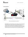
RTK Bridge–C™ HSPA/EDGE/GPRS/GSM Version P/N: FIP1-400RTK-HCE User Guide This manual is for use by purchasers and other authorized users of Intuicom Products. No part of this document may be reproduced, translated, or transmitted in any form or by any means, electronic or mechanical, or for any purpose without the express written permission of Intuicom Inc. Intuicom reserves the right to change technical specifications or functions of its products, or to discontinue the manufacture of any of its products or to discontinue the support of any of its products, without any written announcement and urges its customers to confirm that the information at their disposal is valid. Intuicom reserves the right to make changes to this manual without notice. Unless otherwise agreed to in writing, Intuicom assumes no responsibility or liability for the use of this manual or for the infringement of any copyright or other proprietary right and Intuicom shall deem nothing contained in this manual a warranty or guarantee. Intuicom, 1200 Data Link, and RTK Bridge are trade names of Intuicom, Inc. Other product names mentioned in this manual may be copyrights, trademarks, or registered trademarks of their respective companies and are hereby acknowledged. © 2000 - 2013 Intuicom Incorporated. All rights reserved. Intuicom RTK Bridge–C User Guide (UHF Radio) V2.2 Table of Contents Important Notice ........................................................................................................................................... v Restrictions on Use ........................................................................................................................................ v Product Conformity ...................................................................................................................................... vi Product Safety Notices .................................................................................................................................viii Introduction ................................................................................................................................................... 9 Chapter 1 Product Overview.................................................................................................................. 10 Product Overview ........................................................................................................................................ 11 Key Features.......................................................................................................................................................... 11 Some typical examples of the benefits of the RTK Bridge include:..................................................................... 12 Example Applications ........................................................................................................................................... 13 Chapter 2 Getting to Know Your Intuicom RTK Bridge-C .................................................................... 16 Front Panel Configuration ............................................................................................................................ 17 Understanding the LED Behavior ................................................................................................................. 18 Chapter 3 ..................................................................................................................................................... 20 Activation and Configuring Profiles .............................................................................................................. 20 Device Configuration.................................................................................................................................... 21 Proper Cabling Configuration ....................................................................................................................... 22 Insert SIM Card ............................................................................................................................................ 22 Configuring with Intuicom RTK BridgePro™ Software .................................................................................. 23 Connecting the RTK Bridge-C for Activation/Configuration .......................................................................... 24 Activating the Cellular Modem/ Setting Connection Configurations............................................................. 25 Confirmation of Activation and Operation ................................................................................................... 27 Profile Configuration .................................................................................................................................... 29 Setting Profiles ...................................................................................................................................................... 29 Configuration Profiles ........................................................................................................................................... 29 Chapter 4 (Radio Tab) Internal Radio Configuration ..................................................................................... 32 Internal UHF Radio Channel Configuration ................................................................................................... 33 Chapter 5 Operating in the Field ........................................................................................................... 36 Setup Steps for Operation............................................................................................................................ 37 Understanding the Startup Sequence .......................................................................................................... 39 Monitoring Current Operation Status (PC required) ..................................................................................... 40 Using the Intuicom RTK Bridge as a Base Radio. ........................................................................................... 40 Antenna Aiming for Fixed Mounts / Cellular Signal Strength Mode.............................................................. 44 Possible Antenna Configurations for Tripod Mounts .................................................................................... 46 Changing Profiles on the Fly ......................................................................................................................... 47 Optimizing Wireless Performance ................................................................................................................ 48 Connecting to a Third-Party Radio................................................................................................................ 49 Intuicom RTK Bridge–C User Guide (UHF Radio) V2.2 Chapter 6 Troubleshooting........................................................................................................................... 52 Common Issues and Solutions...................................................................................................................... 53 Appendices .................................................................................................................................................. 57 APPENDIX 1: Technical Specifications ......................................................................................................... 58 APPENDIX 2: Configuration Records Charts ................................................................................................ 59 Configuration Profile Table: ................................................................................................................................. 59 Connection Configuration Setup Table: ............................................................................................................... 60 APPENDIX 3: Narrowbanding Compliance.................................................................................................... 61 APPENDIX 4: Wireless Carrier APN Parameters (HSPA/EDGE/GPRS/GSM Networks only)......................... 62 APPENDIX 5: Connector Pinout ................................................................................................................... 63 APPENDIX 6: Limited Warranty ................................................................................................................... 64 APPENDIX 7: Technical Support .................................................................................................................. 66 Accessories and Replacement Parts ............................................................................................................. 67 Intuicom RTK Bridge–C User Guide (UHF Radio) V2.2 Important Notice Intuicom software, firmware, and programs are delivered “as-is”. The manufacturer does not grant any type of warranty including guarantees of suitability and applicability to a certain application. Under no circumstances is the manufacturer or developer of any software, firmware or program responsible for any possible damages resulting from a use of any software, firmware or program. The names of any software, firmware, or program as well as any copyrights relating to the software, firmware or program are the sole property of Intuicom, Inc. Any transfer or licensing to a third party, leasing, renting, transportation, copying, editing, translating, modifying into another programming language, or reverse engineering for any intent is expressly prohibited without the express written permission of Intuicom, Inc. INTUICOM PRODUCTS HAVE NOT BEEN DESIGNED, INTENDED, NOR INSPECTED FOR USE AS PART OF ANY LIFE-SUPPORT RELATED DEVICE OR SYSTEM, NOR AS PART OF ANY CRITICAL SYSTEM AND ARE GRANTED NO FUNCTIONAL WARRANTY IF THEY ARE USED IN ANY PART OF SUCH APPLICATIONS Restrictions on Use The Intuicom RTK Bridge–C (C3) UHF HSPA/EDGE/GPRS/GSM version contains a UHF radio modem module which has been designed to operate on 403-470 MHz, the exact use of which differs from one region and/or country to another. The user must take care that the device is not operated without the permission of the local authorities on frequencies other than those specifically reserved and intended for use without a specific permit or license. WARNING! Users of the Intuicom RTK Bridge–C UHF-GSM/GPRS/EDGE version containing a UHF radio modem module in North America should be aware that due to the allocation of the frequency band 406.0-406.1 MHz for government use only, the use of a device on these frequencies without a proper license is strictly forbidden. Intuicom RTK Bridge–C User Guide (UHF Radio) V2.2 Product Conformity Intuicom RTK Bridge–C User Guide (UHF Radio) V2.2 Intuicom RTK Bridge–C User Guide (UHF Radio) V2.2 Product Safety Notices Read all instructions before operating device Operate only in accordance with the law and this user guide. Any warranty will be void if the product is used in a way contradictory to the instructions in this manual or if the product has been opened or tampered with. Only use Intuicom supplied cable assemblies, antennas and accessories Do not open or disassemble the device – could result in electric shock. Power the RTK Bridge–C through only one port (P1 or P2) at a time Keep body one meter away during operation. Be sure all antennas are correctly and securely connected before connecting power Do not place unit where antennas risk contact with any electrical wires For indoor use only when using AC/DC adapter, for Indoor/Outdoor use when using a battery or other DC connection. Any third party DC supply must be fused at no greater than 10A in-line. Use caution to avoid electrical shock when connecting or disconnecting power cables. Connect the country specific power cable to the AC/DC adapter prior to connecting the power plug to power source/outlet. Not all accessories may be authorized or legal in all countries or regions Intuicom RTK Bridge–C User Guide (UHF Radio) V2.2 Introduction Welcome to your Intuicom RTK Bridge–C User Manual. This comprehensive guide covers all RTK Bridge-C products and will guide you through the steps to operate your specific model — so you can quickly begin to enjoy the benefits of the precision GPS solutions made possible by Intuicom. After introducing you to the basic design of the RTK Bridge–C, we’ll cover how to perform the one-time setup on your device, as well as how to configure up to four customized profiles to make your time in the field more productive. Intuicom RTK Bridge–C User Guide (UHF Radio) V2.2 Chapter 1– Product Overview Chapter 1 Product Overview Product Overview Key Features Common Usage Scenarios Intuicom RTK Bridge–C User Guide (UHF Radio) V2.2 Chapter 1– Product Overview Product Overview The Intuicom RTK Bridge – C greatly expands access to GNSS network RTK corrections for rover users in the fields by extending cellular coverage and replacing the need for RTK Base stations. The RTK Bridge – C UHFHSPA/EDGE/GPRS/GSM combines a UHF Wireless Data Radio with embedded GPS and cellular HSPA/EDGE/GPRS/GSM Internet connectivity to support a wide range of deployment configurations. Key Features Embedded HSPA/EDGE/GPRS/GSM cellular modem Intuitive software interface Connect to any NTRIP Caster and stream any data/messages/corrections, etc. IBSS and NTRIP2 support. Connect to Raw/Dedicated TCP Sockets (non NTRIP) with or without authentication The RTK Bridge–C’s embedded GPS can provide unit’s position to the GNSS network server for individualized corrections or virtual reference station creation. Optionally enter a user supplied fixed location or stream GGA messages from an external connected source. Embedded UHF data radio can be configured for SATEL 3AS, PCC (9600/4800 GMSK/19200/9600 4FSK) or TRIMTALK to broadcast corrections to receiving data radios. Copy of correction data stream available on a front-panel RS232 serial port for either direct connection to a rover, or connection to an external base radio. Store up to four configuration sets called “Profiles” that can be selected for use in the field – a profile contains configuration data such as server IP, port number, username, password, mount point, location, radio channel, front panel data port baud, etc. Store and select up to three dialing profiles allowing for a mix of connectivity options without requiring configuration changes including the use of different SIM cards . Water resistant and industrial hardened with extended temperature range. Intuicom RTK Bridge–C User Guide (UHF Radio) V2.2 Chapter 1– Product Overview Some typical examples of the benefits of the RTK Bridge include: Using cellular networks to obtain individualized corrections to field rovers via radio link. This is the most typical application. Supplementing an existing wireless network by connecting to an external radio. Corrections can then be broadcast on more than one frequency, and/or more than one protocol simultaneously. Extending wireless carrier data service reach to rovers working in areas without cellular coverage. These are described in more detail on the following pages. Intuicom RTK Bridge–C User Guide (UHF Radio) V2.2 Chapter 1– Product Overview Example Applications 403-470 MHz UHF Satel, PCC, Trimtalk Internet Wireless Carrier HSPA/EDGE/GPRS/GSM Wireless Internet/Data RTCM 3.x RTCM 2.x CMR/CMR+ Leica, FKP, etc. Intuicom RTK Bridge RTK Rover RTK Corrections Machine Control Construction GNSS RTN Server NTRIP/IBSS/TCP Sockets TopNet Spider GPSNet, Geo++, etc Agriculture Figure 1: Intuicom RTK Bridge-C Connection Overview Typical Application - The Intuicom RTK Bridge has a flexible configuration and can be used to satisfy a range of connectivity needs. Commonly, installations have the RTK Bridge configured to connect to an NTRIP Caster where the RTK Bridge supplies as user configured mount point name and authentication credentials. Once connected to an NTRIP mount point, the RTK Bridge sends its GPS point position (from its internal L1 GPS) to the RTN Server allowing the GNSS RTN Server to generate individualized corrections or create a virtual reference station. The unit receives these corrections via IP and then re-broadcasts them to receiving RTK rover units via its embedded UHF Data Radio. Intuicom RTK Bridge–C User Guide (UHF Radio) V2.2 Chapter 1– Product Overview 403-470 MHz UHF Satel, PCC, Trimtalk Internet Wireless Carrier HSPA/EDGE/GPRS/ GSMWireless Internet/Data RTCM 3.x RTCM 2.x CMR/CMR+ Leica, FKP, etc/ Intuicom RTK Bridge RTK Corrections GNSS RTN Server NTRIP/IBSS/TCP Sockets TopNet Spider GPSNet, Geo++, etc RTK Rover Machine Control Construction Agriculture Copy of RTK corrections output on P2 RS232 Serial 4800-115200 Baud Optional 3rd Party Base Radio PacCrest/ Trimble/Topcon/SATEL, etc. Figure 2: Intuicom RTK Bridge-C with third-party base radio Leveraging Existing Data Radios - The Intuicom Wireless RTK Bridge can be used to supplement and existing wireless network, replacing the local base station GPS. Users simply connect a second data radio to the P2 port on the front of the unit to broadcast a copy of the correction stream. If no rover RTK users are utilizing the internal wireless data radio, the internal radio can be disabled to conserve power. Additionally, by connecting to an external radio, one can broadcast corrections on more than one frequency, and/or more than one protocol simultaneously. Intuicom RTK Bridge–C User Guide (UHF Radio) V2.2 Chapter 1– Product Overview Intuicom RTK Bridge 403-470 MHz UHF Satel, PCC, Trimtalk HSPA/EDGE/GPRS/GSM Wireless Internet/Data Wireless Carrier Internet RTCM 3.x RTCM 2.x CMR/CMR+ Leica, FKP, etc. RTK Rover RTK Corrections Machine Control Construction GNSS RTN Server NTRIP/TCP Sockets TopNet Spider GPSNet, Geo++, etc. Agriculture Figure 3: RTK Bridge-C Extending Carrier Data Network Extending Wireless Carrier Data Service Reach – In this example, rovers are operating in an area without HSPA/EDGE/GPRS/GSM cellular data service. The rovers however are still within the network of GNSS reference stations and thus can benefit from network corrections. Using a high gain antenna on the HSPA/EDGE/GPRS/GSM cellular modem, a reliable connection can be established allowing the RTK Bridge to connect to the Internet and the GNSS network server. Corrections are streamed from the GNSS network server to the RTK Bridge where they are broadcast via the embedded UHF Data Radio to all RTK rovers. Note that in this application, any number of Rover users can receive the same correction messages broadcast from the RTK Bridge. Furthermore, if the distance between the RTK Bridge and the rover users is great – the RTK Bridge can be configured to report its position to the GNSS Network server as if it were in the location of the rovers – thus obtaining the most appropriate RTK corrections. Intuicom RTK Bridge–C User Guide (UHF Radio) V2.2 Chapter 2– Getting to Know Your Intuicom, RTK Bridge-C Chapter 2 Getting to Know Your Intuicom RTK Bridge-C Front Panel Configuration Understanding LED Behavior Intuicom RTK Bridge–C User Guide (UHF Radio) V2.2 Chapter 2– Getting to Know Your Intuicom, RTK Bridge-C Front Panel Configuration The front panel controls and inputs are designed to help you quickly and easily set up your device to get the most efficiency out of your operations. Taking a few moments now to familiarize yourself will make setup that much easier. Figure 4: RTK Bridge – C Front Panel 1 2 3 4 5 6 7 8 9 P1 - RS232, Configuration / Power (12VDC) P2 - RS232, Data Out / External GPS Input (NMEA GGA) / Power (12VDC) PROFILE Selection / Mode Select Button Current Profile Indication / Cellular Signal Strength Indication (Antenna Aiming Mode) Status LEDs Power On/Standby. Does not isolate internal DC power circuits or disconnect external power supply. TNC antenna connector for internal HSPA/EDGE/GPRS/GSMModem TNC antenna connector for internal L1 GPS TNC antenna connector for internal 403-470 MHz UHF Data Radio Intuicom RTK Bridge–C User Guide (UHF Radio) V2.2 Chapter 2– Getting to Know Your Intuicom, RTK Bridge-C Understanding the LED Behavior There are eleven green LEDs visible on the front panel. Below are brief explanations on how to interpret each set of indicators. Figure 5: RTK Bridge-C LED Displays A – Vertical LEDs indicate which Profile you have chosen and modem signal strength. In normal operation, the LEDs labeled 1-4 indicate the currently selected Configuration Profile. In antenna alignment mode, the LEDs are used as a bar graph to indicate cellular signal strength. B – Horizontal LEDs provide a real-time status display for the unit: TXD – Indicates data being transmitted out the internal Intuicom Wireless Data Radio, and/or the Data port (P2) on the front panel. SVR – Indicates a successful network connection to the IP socket (either RAW or NTRIP). The SVR LED is not lit during Direct-Dial connections. MDM – Indicates a successful connection to the cellular carrier’s IP network (and thus the Internet). The MDM LED flashed while a Direct-Dial connection is being established and becomes solid after a successful connection. Intuicom RTK Bridge–C User Guide (UHF Radio) V2.2 Chapter 2– Getting to Know Your Intuicom, RTK Bridge-C SIG: LED Solid Green Flashing Green Off DESCRIPTION Indicates a strong cellular signal as sampled during the power-up/boot-up stage Indicates a marginal cellular signal – communication may or may not be possible. Indicates a very weak or absent cellular signal – it is very unlikely communications will be possible. GPS: LED Solid Green Flashing Green Off DESCRIPTION Internal GPS is selected for use in the current Profile and is tracking Internal GPS is selected for use in the current Profile, and the GPS is not tracking or Data Port is selected to receive GGA messages from an external GPS and either these messages are not being received, or the external GPS is not tracking. Either a Static position has been selected or the sending of a GPS position to the server is disabled. PWR – When illuminated indicates that the unit is powered and has been turned on. Intuicom RTK Bridge–C User Guide (UHF Radio) V2.2 Chapter 3 – Activation and Configuration Profiles Chapter 3 Activation and Configuring Profiles HSPA/EDGE/GPRS/GSM activation Profile Configuration Intuicom RTK Bridge–C User Guide (UHF Radio) V2.2 Chapter 3 – Activation and Configuration Profiles Device Configuration The Intuicom RTK Bridge – C must be configured and populated with a data service activated SIM card prior to use. This section covers both configuring the device for a specific wireless carrier/SIM card as well as configuring the unit to connect to a GNSS Network server (via NTRIP 1.0, NTRIP 2.0, IBSS, TCP/IP). For the Intuicom RTK Bridge to connect to a GNSS RTN Network server, a configuration unique to the specific GNSS RTN Network server is required. The unit can store up to four configurations called “Configuration Profiles”. For convenience the current Configuration Profile can be changed in the field without the need of a PC. Configuration Profiles enable the user to perform tasks such as change NTRIP mount points, change GNSS RTN servers, change how locations sent to the server, change how the unit connects to the cellular network, change SIM card parameters, etc. At least one Configuration Profile must be correctly configured for successful operation. For example, a user may want to have one Profile connect to a network correction stream and another Profile connect to a single baseline correction from the nearest reference station and be able to change between the two in the field. Another example might be the situation where the device is moved between locations and at each location there is a different external data radio with a different baud rate – while both locations may want the same correction stream, the Configuration Profiles provide an easy way to change the baud rate for the external Data Port. Each Configuration Profile points to one of three “Connection Configs” to use when the cellular modem is connecting to the Internet. Each Connection Config contains the carrier specific parameters such as APN name, username and password. If the unit is to be used with more than one SIM card, it is helpful to configure one Connection Config for each SIM card. Intuicom RTK Bridge–C User Guide (UHF Radio) V2.2 Chapter 3 – Activation and Configuration Profiles Proper Cabling Configuration Below is the recommended cabling for initialization and activation of the RTK Bridge-C (regardless of what type of cellular network you are utilizing) Figure 6: Cable Connections for Accessing Configuration Menu Insert SIM Card The first step is to insert the SIM card into a non-powered RTK Bridge-C. Then you can power up and connect to the unit with Intuicom’s RTK BridgePro software. Note: Inserting or Removing a SIM from a powered up RTK-M Bridge may result in damage to the RTK Bridge-C and the SIM itself. Intuicom’s RTK BridgePro software will automatically detect the RTK Bridge-C model it is configuring. The software will display the Modem type: “HSPA” that designates a SIM-based model. Intuicom RTK Bridge–C User Guide (UHF Radio) V2.2 Chapter 3 – Activation and Configuration Profiles Configuring with Intuicom RTK BridgePro™ Software Intuicom RTK BridgePro Software is included on a CD that shipped with your RTK Bridge–C. Install this software on your PC by simply copying this executable file to your desktop or to a folder. This software requires Microsoft’s .NET Framework 3.5, which may require you to download them from the Microsoft website. The RTK BridgePro software automates most of the process for you. It will automatically detect what type of cellular network you are attempting to connect to, whether you have a radio installed and what type of radio, and whether you have onboard GPS! Further, you can learn about individual software menus by hovering your cursor over them. An explanation and helpful hints will be displayed. Once the software is loaded and launched, you monitor should display a window as shown in Figure 6. The Software interface can be divided into two parts: Live Status: Provides a Real-Time display of the status and operation of the RTK Bridge-C. This includes, but is not limited to: Profile selection, Cellular status, Connectivity to RTN. Configuration: Provides the ability to set-up your RTK Bridge-C, Register/Activate your cellular connection, configure your login parameters, and more. Live Status Configuration Figure 7: Intuicom RTK BridgePro Software main screen Intuicom RTK Bridge–C User Guide (UHF Radio) V2.2 Chapter 3 – Activation and Configuration Profiles Connecting the RTK Bridge-C for Activation/Configuration 1. Connect the GSM antenna, the GPS antenna and the UHF antenna as shown in Figure 4. 2. Confirm that an activated SIM card has been inserted in the SIM card slot in the proper slot. 3. Connect the Lemo end of the Power/Data cable to port P1 of the RTK Bridge. Connect the DB9 connector of the Power/Data cable to an available DB9 COM port on the PC to be used for configuration. If no COM port is available, a USB-COM port adapter may be used. Attach the ACDC power adapter to the power connector on the Power/Data cable and plug the AC adapter into an AC outlet. Be sure to use the appropriate region/country specific power adapter. Once the RTK Bridge-C is connected to a COM port on the PC (through Port 1 on the front of the device), you can connect the software to the unit by selecting the appropriate COM port and selecting “CONNECT” in the upper left corner of the interface. Follow this by applying power to the RTK Bridge-C. Note: If you are connecting to a SIM-based RTK Bridge-C, this process requires that you have installed an active SIM with a valid data service plan BEFORE applying power to the device. Initially, the software will reflect the Live Status of the RTK Bridge-C unit. If you have not registered or activated the modem, the software will reflect that the Modem Registration is “Unknown” on the network and the other fields display in the Live Status section will reflect this non-registered/inactive state, see Figure 8. Figure 8: Initial LIVE STATUS screen of a non-registered RTK Bridge-C Intuicom RTK Bridge–C User Guide (UHF Radio) V2.2 Chapter 3 – Activation and Configuration Profiles Activating the Cellular Modem/ Setting Connection Configurations Once the connection is established, the first step is to activate your internal modem. This will be accomplished by selecting the “Config Mode” button at the top of the software interface. This will activate the Configuration portion of the software. Figure 9: Initial CONNECTIONS screen for a SIM-based RTK Bridge-C On the Connections page, the Connection Configuration #1 is pre-configured for AT&T (in the United States), but may be altered if you require a different APN or other parameters. Please enter or confirm your parameters. Any changes you make in the software is not loaded onto the RTK Bridge-C until you select the “Apply Config” button at the top of the software (Figure 10.) The RTK Bridge-C also offers the ability to store two more unique cellular carrier configurations (Configurations #2 and #3). If you care to configure these, gather the necessary information and enter it into the “Config 2” and/or “Config 3” menus. Note: Selecting the APPLY CONFIG button is required to load/store any configuration changes to the RTK Bridge-C. Intuicom RTK Bridge–C User Guide (UHF Radio) V2.2 Chapter 3 – Activation and Configuration Profiles Figure 10: Apply Configuration” Loads the Configuration onto the RTK Bridge-C Intuicom RTK Bridge–C User Guide (UHF Radio) V2.2 Chapter 3 – Activation and Configuration Profiles Confirmation of Activation and Operation Confirmation of Activation and proper operation of the RTK Bridge-C is easily accomplished with Intuicom’s RTK BridgePro software. While in Configuration Mode, select the “Profiles” tab. In the Profiles menu, there is a pull down for the “Active Profile”. Select Profile #4. (See Figure 11.) Profile #4 is pre-loaded with the proper settings to connect with Intuicom’s Real-Time Network server. Figure 11: Active Profile Selection >> #4 in the Configuration Mode With Profile #4 selected, click on the “Apply Config” button as shown in Figure 3.5. Next, proceed by selecting the “Status Mode” button to enter the LIVE STATUS mode of operation. This selection will bring up a reminder window to confirm you have “Applied Config” and that you are exiting the Configuration Mode (Figure 12). Intuicom RTK Bridge–C User Guide (UHF Radio) V2.2 Chapter 3 – Activation and Configuration Profiles Figure 12: Reminder to Confirm the Exit of Configuration Mode Selecting Live Status mode will cause the RTK Bridge-C to restart. Take notice that the profile #4 is being utilized as is indicated by the #4 Profile LED blinking during this initial re-start. Allow a few moments for the RTK Bridge-C to proceed through its start-up process. During this time, note the Live Status fields will be updating. Positive outcome is presented as follows: 1. The “MODEM CONNECTION” will read “Established” if the internal modem is activated and properly configured. 2. The “SVR CONNECTION” reads “Successful Connection” indicating the RTK Bridge-C is fully operating, utilizing the Profile #4 which connects to Intuicom’s Real-Time Server. 3. The “TxD DATA FLOW” displays “Active” indicating corrections are being sent out from the RTK Bridge-C. Figure 13: Live Status showing successful operation Now we have activated the cellular modem, set up to three Connections Configurations, and confirmed activations, we can proceed to configuring up to four unique Profiles. Intuicom RTK Bridge–C User Guide (UHF Radio) V2.2 Chapter 3 – Activation and Configuration Profiles Profile Configuration In order for the he Intuicom RTK Bridge-C to connect to a GNSS RTN Network server, a configuration unique to the specific GNSS RTN Network server is required. The unit can store up to four configuration sets called “Configuration Profiles”. The current Configuration Profile can be changed in the field without the need of a PC. As mentioned earlier, Profiles enable the user to perform tasks such as change NTRIP mount points, change GNSS RTN servers, change how locations are sent to the server, change how the unit connects to the cellular network, change SIM card parameters (if using a GSM network,) etc. At least one Configuration Profile must be correctly configured for successful operation. The factory default settings for the RTK Bridge specify the most common connection type (IP/NTRIP with packet-switched-data) and often very little configuration is required. Setting Profiles Once activated, the Intuicom RTK Bridge-C is configured to work with your Real-Time Network. Using the software as we have in the previous set up and activation steps, this configuration is easily accomplished. Next, we will proceed to set up a Profile specific to your application. Figure 14: "Profile" Tab on Configuration Software Configuration Profiles The Intuicom RTK Bridge–C stores four Configuration Profiles, of which only one can be active at a time. A Configuration Profile contains the necessary parameters for connecting to a data stream of RTK correction messages and forwarding them out the data port to a GNSS Rover. Prior to configuration, it is helpful to have the following pieces of data available: Connection Mode – Either NTRIP, RAW TCP, IBSS, or NTRIP2 Connection Config. – This is the Connection Configuration # (1-3). Previously we set up Connection #1 Server Host Name – IP Address of the Real-Time Server Intuicom RTK Bridge–C User Guide (UHF Radio) V2.2 Chapter 3 – Activation and Configuration Profiles Server Port – Server Port Number Mount point Name – Name of the mount point you will connect to (case-sensitive) User Name – If authentication is required, you will need to have a user-name Password – If authentication is required, you will need to have a password P2 Baud Rate* -- Baud rate must match up with the equipment you are connecting to GPS – If GPS is required, select the appropriate GPS positioning method Connection mode, server host name, server port, mount point name, user name, and password may all be obtain from your RTN provider. * The baud rate for the Data Port (P2) on the front panel of the device – this will be the baud rate needed to interface to a third party external data radio. Be sure to match the baud rate you’re connecting to with (commonly 38.4) These configuration parameters are then entered or selected in the Intuicom RTK BridgePro software as shown in Figure 15. Based on the type of correction stream to which the unit will be connecting – determine if a GPS (GGA NMEA) message needs to be sent and if so, should the message be generated in real-time from the embedded GPS, be supplied from an external source via the Data port, or should the message relay a fixed, user supplied position. Intuicom RTK Bridge–C User Guide (UHF Radio) V2.2 Chapter 3 – Activation and Configuration Profiles Figure 15: Selecting Connection Config from Profile Configuration Mode Once you have completed entering the profile parameters, you must select the “Apply Config” button at the top of the page to load these setting onto the RTK Bridge-C. Figure 16: "Apply Config” Loads the Configuration onto the RTK Bridge-C Next, select Status Mode, The RTK Bridge-C will restart. Successful operation will be displayed in the Live Status page as shown in Figure 13 as well as on the front panel of the RTK Bridge-C. Intuicom RTK Bridge–C User Guide (UHF Radio) V2.2 Chapter 4 – Internal Radio Configuration Chapter 4 (Radio Tab) Internal Radio Configuration Internal UHF Radio Configuration (If Included) Configuration Record Chart Intuicom RTK Bridge–C User Guide (UHF Radio) V2.2 Chapter 4 – Internal Radio Configuration Internal UHF Radio Channel Configuration The RTK Bridge-C incorporates a UHF Data Radio capable of up to 1000mW of transmit power. The internal radio can be enabled or disabled. If enabled, the user can configure and specify which “channel” to use. The user configures a “bank” of channels where each “channel” contains properties such as: Frequency, Power, Protocol, Channel Width, Error Correction mode, etc. Thus the “channel” specified in a configuration Profile is actually a composite of a number of radio parameters – when the “channel” is changed, the Intuicom RTK Bridge automatically configures all radio parameters associated with the selected channel. This enables easy in-the-field changes allowing the unit to easily communicate with a variety of vendors’ receive radios. See Internal Radio Channel Configuration for details. You may configure up to eight separate channels. Once you have selected a channel to configure, you will be asked to input five parameters for each channel: Frequency Power Channel Width OTA Protocol FEC Select the “UHF Channels” Tab to access the radio configuration menu and input the desired parameters. Intuicom RTK Bridge–C User Guide (UHF Radio) V2.2 Chapter 4 – Internal Radio Configuration Figure 17: Configuration Input Menu for UHF Radios Frequency – The radio frequency (403-470 MHz). Specify the entire frequency 4xx.xxxxx. Power – The data radio transmit power – select 100, 200, 500 or 1000mW Channel Width – Select either 25 kHz or 12.5 kHz channel widths. OTA Protocol – Select either SATEL 3AS, PCC GMSK 9600 or PCC 4-FSK 19200 protocols (Trimtalk coming soon). When configuring the receiving data radios, note: Satel 3AS – When the receiving radio is a SATEL 3AS be sure to match the frequency, channel width, and FEC mode. PCC GMSK 9600 – When the receiving radio is a PCC configured for the GMSK protocol with 9600 baud over the air data rate, be sure to match the frequency, the channel width, as well as configure the receiving radio to enable error correction and enable scrambling. PCC 4FSK – When the receiving radio is a PCC configured for the 4FKS protocol with 19200 baud over the air data rate, be sure to match the frequency, the channel width, as well as configure the receiving radio to enable error correction and enable scrambling. Intuicom RTK Bridge–C User Guide (UHF Radio) V2.2 Chapter 4 – Internal Radio Configuration Note that when using the PCC GMSK or 4FSK protocols; configure the receiving radio to have error correction on and scrambling enabled. TRIMTALK – Protocol to communicate with other TRIMTALK compatible receive radios. FEC – Select whether SATEL Forward Error Correction is enabled or disabled. This parameter is only valid when the protocol is set to SATEL 3AS – with all other protocols, leave this parameter set to “OFF”. Be sure and write down your radio configuration settings on the chart in the back of this document for convenient future reference. Intuicom RTK Bridge–C User Guide (UHF Radio) V2.2 Chapter 5 – Operating in the Field Chapter 5 Operating in the Field Setup Steps for Operation Understanding the Startup Sequence Monitoring Current Operation Status Antenna Aiming for Fixed Mounts / Cellular Signal Strength Mode Changing Profiles on the Fly Optimizing Wireless Performance Connecting to a Third Party Radio Intuicom RTK Bridge–C User Guide (UHF Radio) V2.2 Chapter 5 – Operating in the Field Once configured and physically set up for operation the unit will go through a startup routine when powered on, connect to the GNSS network server, and begin broadcasting corrections. Setup Steps for Operation 1. Connect Wireless Data Antenna – Connect the UHF antenna (FIP4-400ANT-013-4R ) to the TNC RADIO connector on the front of the unit. Optionally the antenna could be a higher-gain omnidirectional antenna or a directional yagi antenna. Contact Intuicom or your dealer for more information about optional higher gain UHFantennas and cabling. Position the antenna to provide the best coverage for your application. In general, antenna height makes a significant difference in range and performance. “Height is everything.” 2. Connect GPS Antenna – If the configuration utilizes the embedded GPS to obtain a correction stream, be sure to attach the L1 GPS antenna (FIP4-GPSL1-RTK) to the TNC connector on the front panel and position the antenna such that it has good visibility to the sky. 3. Connect Modem (Cellular) Antenna – Connect the appropriate Cellular antenna to the Modem antenna connector on the front panel. This antenna will be the included “duck” antenna (FIP4GSMANT-AT) or an optional directional panel antenna. If the unit is located in weak wireless coverage, a directional panel antenna may be necessary to successfully connect to the network. See Cellular Modem Antenna Aiming Mode in Section 0. 4. Insert activated SIM card in the SIM socket as outlined earlier. Be sure selected Profile and Connection Config are appropriate for SIM. 5. Connect to P2 Port for copy of correction stream (optional) – If copies of the correction are to be broadcast using an external third-party base radio, connect the appropriate cable and ensure the baud rates match. If the standard power/data cable (FIP4RTKPWDATA) is used, a null modem or gender changer may be required. Intuicom manufactures dedicated cables for connections to some external radios, eliminating the need to connect DB9 ends together. It is also possible to connect directly to an RTK Rover GPS for testing using the P2 Port. 6. Connect Power – The RTK Bridge can be powered using either the P1 or the P2 port. There are a number of cabling options for powering the unit. Figure 18 pictures the different options. Power can be applied using the standard power/data cable (FIP4-RTKPWDATA) and attaching either the AC-DC converter, or the DC power pigtail cable (FIP4-RTKPG-DC). If just power alone is required (no data), then the Lemo to SAE power cable (FIP4-RTKPW) can be used instead of the power/data cable. Intuicom manufactures cables for directly connecting to different GPS manufacturers accessory batteries – See Accessories for cable part numbers. Intuicom RTK Bridge–C User Guide (UHF Radio) V2.2 Chapter 5 – Operating in the Field CAUTION: Only connect 12-24 VDC power using only Intuicom supplied cabling. Only connect one source of power at a time. 7. Power On - Make sure the device is located within cellular coverage and turn-on power by pressing and holding the green power button until the PWR LED lights green. CAUTION: Only connect 12-24 VDC power using only Intuicom supplied cabling. Only connect one source of power at a time. Intuicom P/N: FIP4-GPSL1-RTK Intuicom P/N: FIP4-400ANT-013-4R (UHF) FIP4-900ANT-XXXX (900 MHz) Intuicom P/N: FIP4-GSMANT-AT P1 I P2 Intuicom P/N: FIP4-RTKPWDATA Intuicom P/N: FIP4-PSCE-5A Intuicom P/N: FIP4-PCUK-CE FIP4-PCEU-CE FIP4-PCUS-CE Intuicom P/N: FIP4-RTKPG-DC Intuicom P/N: FIP4-RTKPW Intuicom P/N: FIP4-RTKCAB-TCB Figure 18: Antenna and cabling options for the RTK Bridge-C If using an agricultural model RTK Bridge-C, the device will power up automatically when connected to the agricultural equipment. Intuicom RTK Bridge–C User Guide (UHF Radio) V2.2 Chapter 5 – Operating in the Field Understanding the Startup Sequence Once the unit is properly configured and physically setup and powered on, it goes through a startup sequence when power is attached and power button ( seconds. ) pressed and held for approximately three 1. The currently active Configuration Profile LED (1-4) will blink for a few seconds – while the current Profile LED is blinking, press the Profile button to change the active Profile. If the Profile is changed, the unit will re-start with the new Configuration Profile. 2. The Cellular signal strength is sampled – and the SIG light will indicate the current Cellular signal strength: Solid GREEN for strong signal, Flashing GREEN for adequate signal, or OFF of weak or inadequate signal. 3. If the cellular signal strength is sufficient, the unit will connect to the Internet, a successful connection is indicated by the MDM light turning GREEN. 4. The unit will attempt to connect to the Server IP and Port number specified in the currently selected Configuration Profile, if this connection is successful, the SVR LED will turn GREEN. 5. If the current Configuration Profile is set to NTRIP mode, the unit will attempt to connect to the configured mount point using the configured username and password. If this fails (possibly because of bad mount point, username or password), the SVR LED will turn off. 6. If the unit is configured to send it’s Real-Time, or Static GPS message, it will do so within 10 seconds. The GPS LED will indicate if the internal (or externally connected) GPS is tracking, or if a Static GPS message is being sent. 7. The TXD LED will begin to blink as corrections are received and broadcast out the internal data radio and/or the Data port on the front panel. Operation will continue until interrupted by power off, or loss of cellular signal or some other Internet connectivity interruption. 8. The RTK Bridge will sense an interruption in corrections and will attempt to re-connect, or restart as necessary to re-establish connectivity and the stream of correction messages. Intuicom RTK Bridge–C User Guide (UHF Radio) V2.2 Chapter 5 – Operating in the Field Monitoring Current Operation Status (PC required) To monitor operations, status messages displayed in Live Status Mode include: Status of the Cellular connection to the Internet. Status of the TCP socket connection to the server (or NTRIP Caster). Status of the GPS Positional Messages – whether or not they are being sent – and if so, the actual message. Status of data received from the server or NTRIP Caster, and its broadcast on the wireless network. The following screenshot of the Live Status menu provides example status messages: Figure 19: Status Messages in the "Live Status" Window Using the Intuicom RTK Bridge as a Base Radio. There may be times when you wish to use your RTK Bridge as a base radio. Setting the unit for operation as a base radio is easily accomplished. Requirements: RTKBridgePro software V 2.3 or higher Firmware version B22 or higher Intuicom RTK Bridge–C User Guide (UHF Radio) V2.2 Chapter 5 – Operating in the Field RTK Bridge-C V2 with an HSPA modem RTK Bridge must be attached to your computer via the programming cable 1. Launch RTK BridgePro software. a. Choose your active Comm Port from the dropdown menu. In this example, COM 4 is selected b. Select “Connect” 2. After successful connection, “Config Mode” becomes selectable. a. Select “Config Mode” Intuicom RTK Bridge–C User Guide (UHF Radio) V2.2 Chapter 5 – Operating in the Field 3. The Config Mode screen appears. a. Select and modify the Profile you wish to modify. Intuicom suggest Profile 4. b. Change Connection Mode to “Base Radio” c. Deselect “Authenticate” d. Disable “Positioning” e. Leave “Internal Data Radio Enabled” (Disable if using an external radio) Intuicom RTK Bridge–C User Guide (UHF Radio) V2.2 Chapter 5 – Operating in the Field 4. Select Appropriate Radio Channels Tab a. Select a radio channel on which to broadcast b. Ensure these settings match the rover radio settings, including Channel number. c. Select “Apply Config” Intuicom RTK Bridge–C User Guide (UHF Radio) V2.2 Chapter 5 – Operating in the Field 5. A dialogue window will appear asking you to confirm your choices. a. Select “OK” 6. Another dialogue box appears confirming successful change to Base Radio mode. The RTK Bridge is now ready to function as a base radio to your GPS/GNSS receiver. Antenna Aiming for Fixed Mounts / Cellular Signal Strength Mode The RTK Bridge – C has a special mode useful when utilizing a directional antenna for the embedded cellular modem. A directional antenna is most useful when operating in an area of weak cellular coverage. The Antenna Aiming Mode allows the user to see signal strength feedback from the front panel of the unit while aiming the directional antenna. Once the signal strength is peaked, the direction antenna can be secured in place. To enter Antenna Aiming Mode, be sure a cellular antenna is attached (often an outdoor panel antenna). Connect power and antennas as outlined previously. While holding the blue profile button, power on the unit and continue holding the profile button until all four profile indicator LEDs (labeled 1-4) flash at the same time. Intuicom RTK Bridge–C User Guide (UHF Radio) V2.2 Chapter 5 – Operating in the Field Release the profile button – the unit is now in Antenna Aiming Mode and will continue in the mode until the unit is powered down. Agricultural model power on automatically, so be sure you are holding the Profile button down as the unit is plugged into a power source. In Antenna Aiming Mode, the profile indicator LEDs (labeled 1-4 on the front panel) will form a vertical bar graph indicating relative signal strength. When none of the LEDs are illuminated, it indicates a weak or non-existent signal, when four lit LEDs indicate a very strong signal. A message with a numerical (dBm) measure of signal strength is simultaneously output on the P2 port. If using this mode for antenna aiming, rotate or aim the optional directional antenna while watching the signal strength indication. Identify the antenna orientation that results in the strongest indicated signal and secure the antenna in that position. Directional antennas on mobile vehicles cannot be aimed properly. Omni-directional antennas are the recommended choice for instances where the antenna will be mobile. Exit the Antenna Aiming Mode by powering down the unit (press and hold the green power button until the PWR LED goes out). Figure 20: Cellular signal strength and antenna aiming Intuicom RTK Bridge–C User Guide (UHF Radio) V2.2 Chapter 5 – Operating in the Field Possible Antenna Configurations for Tripod Mounts Below are the two most common configurations for optimal performance. UHF Duck Antenna GSM/GPRS/EDGE Wireless Connection Intuicom RTK Bridge - UHF 12V Battery Figure 21: Standard Installation with duck antennas UHF Omni Antenna GSM/GPRS/EDGE Yagi Antenna Intuicom RTK Bridge - UHF 12V Battery Figure 22: Typical RTK Bridge field setup using optional antennas Intuicom RTK Bridge–C User Guide (UHF Radio) V2.2 Chapter 5 – Operating in the Field Changing Profiles on the Fly The active Profile can be changed in the field without the use of a PC. At least one Profile must be configured for operation. It is suggested to setup the Configuration Profiles in numerical order, starting with Profile 1. Configuration Profiles are changed in the field by pressing the blue Profile button on the front panel at the appropriate time during the boot up process. To change Profiles, power on the unit and wait for the currently active profile LED to flash (the profile LEDs are in a vertical column labeled 1-4 on the front panel). Immediately upon seeing the currently active Profile LED flash, press the blue profile button – this will result in incrementing the active profile – and the change will be displayed by the lit Profile LED advancing. Continue to press and release the blue Profile button until the desired Profile is selected. The unit will timeout waiting for further changes, then reboot and re-configure for the newly selected active Profile. The selected active Configuration Profile must have been properly configured before being selected. For information about how to configure the parameters for each individual Profile, see Section 2.3. Figure 23: Changing the active profile on the front panel Example: A user has two Profiles configured. Each Profile is basically the same with regard to the GNSS network server, and login credentials – the Profiles differ in the NTRIP mount point names. The user wants to be able to switch from an RTCM 3 correction to a Leica message from a specific reference station. The user can change the RTK Bridge to use the different profile, and change the rover configuration to accept the different correction message type. Intuicom RTK Bridge–C User Guide (UHF Radio) V2.2 Chapter 5 – Operating in the Field Optimizing Wireless Performance Range performance of the internal data radio can be greatly improved by optimizing the radio location and antenna setup. Height is everything. If the RTK Bridge and antenna setup can be located at a highpoint that improves line of sight between its antenna and rover units, the performance can be greatly improved. It may even be desirable to locate the unit farther away, but in location with more height. Key factors affecting wireless performance: 1) Location and height – In general locating the unit as high as possible and/or using a mast for the broadcast antenna can greatly improve wireless performance. 2) Transmit Power. Be sure the embedded data radio is configured to use the highest legal transmit power (power/antenna combination). 3) Antenna type and proper installation and aiming if applicable – If the rover users are located some distance away from where the RTK Bridge is setup, a higher gain antenna may be desirable. Contact Intuicom or your Dealer for more information about optional higher gain antennas and cable assemblies. For the embedded Cellular modem, the included duck antenna may not be adequate. In these cases, use of an optional higher gain cellular antenna may be desirable (such as a directional panel antenna or higher gain omni-directional antenna). Optional higher gain antennas (or their use) may not be legal in all countries/locations. 4) Coaxial cable length and type – When using optional higher gain antennas use quality RF cable and keep antenna cables as short as possible. Avoid using adapters. Use coax that has lower loss for high frequencies – such as Times Microwave LMR240. Avoid using RG-58 cable. 5) Rover antenna type and condition – confirm that the rover users are using the correct antenna. Any additional height that can be added to the rover antenna is useful – such as a backpack with a short pole and adapter for the duck antenna. The rover antenna can significantly affect the overall performance of the system. Intuicom RTK Bridge–C User Guide (UHF Radio) V2.2 Chapter 5 – Operating in the Field Connecting to a Third-Party Radio In addition to broadcasting RTK correction messages via an internal radio (UHF or 900MHz) – the correction messages are available via RS232 on the P2 port on the front panel of the unit. To connect to an external third-party radio: 1. Configure the baud rate of the P2 port on the RTK Bridge to match the baud rate of the thirdparty radio. Each Configuration Profile contains a P2 port baud rate selection. 2. Connect the appropriate third-party data/power cable to both the Intuicom RTK Bridge and the third-party radio. Alternatively the standard Intuicom Data/Power cable could be used to connect to a third-party radio – the user will need to connect the DB9 end of the cable to the third-party radio (or the radio’s cable) – and may need a null-modem and gender changer adapters. 3. Connect each device’s power. Never power the Intuicom RTK Bridge from more than one port at a time – power can be applied to the unit on either the P2 port, or the P1 port – but not both simultaneously. 4. Power up both units and confirm reception of corrections at rover radios receiving from the thirdparty base radio. See the separate part list for cable part numbers for connecting third-party radios. Contact Intuicom or your Dealer for more information about cabling. Intuicom RTK Bridge–C User Guide (UHF Radio) V2.2 Chapter 5 – Operating in the Field Figure 24: Connecting to third-party base radio: PCCLPB Figure 25: Connecting to third-party base radio: PCCHPB Intuicom RTK Bridge–C User Guide (UHF Radio) V2.2 Chapter 5 – Operating in the Field Figure 26: Connecting to third party base radio: SATEL 35W Intuicom RTK Bridge–C User Guide (UHF Radio) V2.2 Chapter 6 – Troubleshooting Chapter 6 Troubleshooting Common Issues and Solutions Advanced Features and Maintenance Intuicom RTK Bridge–C User Guide (UHF Radio) V2.2 Chapter 6 – Troubleshooting Common Issues and Solutions The six LEDs on the front of the RTK Bridge-C provide a real-time update of the status of the device and may be used for troubleshooting. Figure 27: Front Panel LED Status Lights Issue Possible Cause(s) Power is not applied or not turned on No Power LED indicator Incorrect power wiring Non-operable cable assembly Out of Cellular Coverage Unit powers, but SIG LED never lit or blinking Confirm power button has been pressed and held until PWR LED lights. Confirm operating within carrier’s coverage area. No Cellular antenna attached Insufficient Cellular antenna for location Missing or bad GPS antenna Poor coverage – operating indoors GPS LED flashing Solution Confirm power is correctly applied using a good Intuicom supplied cable assembly and power adapter. External GGA message source not tracking or not sending correct message(s) Connect adequate Cellular antenna for location – a higher gain and/or directional antenna may be required in weak coverage areas. Confirm a good GPS antenna is attached to the GPS TNC antenna port on the front panel – orient the antenna outdoors with good sky visibility. If GPS (GGA) messages are provided via an external device on the P2 port, confirm that the device is actually sending messages and that its GPS is tracking. Confirm the unit POSITIONING Intuicom RTK Bridge–C User Guide (UHF Radio) V2.2 Chapter 6 – Troubleshooting mode is configured for REALTIME or P2 PORT. Poor Cellular coverage Missing or bad Cellular antenna MDM LED never lights Incorrect APN/Username/password and/or SIM PIN configuration SIM card not inserted, or bad/not activated Unit unable to establish TCP socket connection to server (SVR LED never lights) Unit unable to connect to NTRIP mount point – sourcetable continuously displayed (via Configuration port status output) Unit appears to connect, but the SVR light goes on and off for a period before the MDM light goes off and the unit reboots. Unit able to establish connection to TCP port, and to configured mount point, but no correction messages are streamed Remote RTK Rover units unable to establish link Confirm operating within the carrier’s coverage area. Confirm good and adequate Cellular antenna is attached, and if applicable, oriented. Confirm activated SIM card correctly inserted. Incorrect Server Address or Port Configuration Configure Server IP Address and Port Incorrect mount point configuration Select valid NTRIP mount point Incorrect username and/or password Username already in use on GNSS server and GNSS server configured to not allow multiple simultaneous logins Valid GPS stream required to be sent to server to obtain corrections No data available from server Channel Configuration incorrect Wrong channel selected Intuicom RTK Bridge–C User Guide (UHF Radio) V2.2 Obtain the correct username and password for your account on the GNSS server. Obtain another username/password (account) or request the GNSS server administrator allow multiple simultaneous logins for your username/password. Turn on the Sending of GPS messages to server Confirm GNSS server is operational and capable of outputting corrections on selected port/mount point Confirm both the RTK Bridge and Rovers have channel configurations that match, and have the same Chapter 6 – Troubleshooting channel selected. No antenna, or bad antenna Confirm good antenna/transmission line and correct antenna attached Remote RTK Rover units link, but do not receive correction messages Third-party radio connected by not transmitting corrections, or rover users unable to receive corrections. Check correction message type and rover configuration – either the correction type on the rover may need to be changed, or the RTK Rover not configured to receive Bridge may need to connect to a the correction message type being different NTRIP mount point or broadcast socket. Correctly configure base and rover Frequency, protocol, or other radio parameters including configuration difference between frequency, channel width, protocol. base and rover radios Make sure interface cable is Interface cable connected to connected to P2 port on RTK Bridge. wrong port on RTK Bridge Make sure baud rate configured in Baud rate mismatch between RTK currently selected Configuration Bridge and external third-party Profile matches that of the external radio. radio (common baud rates are 9600, 19200, or 38400). Correction stream not valid for Rover configuration Intuicom RTK Bridge–C User Guide (UHF Radio) V2.2 Chapter 6 – Troubleshooting Intuicom RTK Bridge–C User Guide (UHF Radio) V2.2 Appendices Appendices Technical Specifications Wireless Carrier APN Parameters (HSPA/EDGE/GPRS/GSM Networks only) Connector Pinout Technical Support Intuicom RTK Bridge–C User Guide (UHF Radio) V2.2 Appendices APPENDIX 1: Technical Specifications Parameter UHF Radios: UHF Transmitter Frequencies UHF Transmitter Power Channel Spacing Protocols Cellular Modem: HSPA/GPRS/EDGE/GSM Modem Connectors: Serial IO Cellular Modem Antenna Port L1 GPS Antenna Port Internal Radio Connector Physical Operating Temperature Range Storage Temperature Range Transportation Temperature Range Operational Voltage/Current Size L x W x H Power (typical) Weight Enclosure Protection Humidity Specification 403-470 MHz 100 mW to 1000 mW, configurable 12.5 or 25kHz, configurable 3AS, PCC (GMSK, 4FSK), TRIMTALK Quad Band: (850, 900, 1800, 1900 MHz) HSPA: 2100 w/o 900 Lemo 1-shell 5-pin (x2) TNC Female TNC Female TNC Female -25 to 55 °C -40 to 70 °C -40 to 70 °C 12-24 (+/-10%) VDC 5A max 150 x 160 x 55mm 5-18W 964g IP54 5-95% non-condensing Intuicom RTK Bridge–C User Guide (UHF Radio) V2.2 Appendices APPENDIX 2: Configuration Records Charts IMPORTANT: Complete the following tables to record the unit’s configuration and for reference when changing Configuration Profiles in the field. Should you need to reset the device or call for customer support, this information will help to more quickly resolve any issues. Configuration Profile Table: PARAMETER 1 CONFIGURATION PROFILE 2 3 Connection Configuration (1,2,3) – SIM-based only Mode: (RAW/NTRIP1/NTRIP2,/IBSS) Server Host Name or IP Address (xxx.xxx.xxx.xxx) Server TCP Port Mount point Name Username Password Authentication GPS Mode Latitude Longitude Internal Radio Enable Internal Radio Channel: Network ID Frequency Key Minimum Packet Size Maximum Packet Size Repeaters Enables (Y/N) Data Port Baud Intuicom RTK Bridge–C User Guide (UHF Radio) V2.2 4 Appendices Connection Configuration Setup Table: PARAMETER 1 CONNECTION CONFIGURATION 2 Dial Method (IP/NTRIP) Username Password APN (HSPA/EDGE/GPRS/GSM only) SIM PIN Intuicom RTK Bridge–C User Guide (UHF Radio) V2.2 3 Appendices APPENDIX 3: Narrowbanding Compliance All Intuicom RTK Bridges with UHF shipped in North America beginning January 1, 2013 comply with FCC regulations regarding narrowbanding requirements. Users will not be able program 25 KHz wide channels but will be limited to 12.5 KHz wide channels. Should users inadvertently attempt to program a 25KHz wide channel they will receive the following error message: Intuicom RTK Bridge–C User Guide (UHF Radio) V2.2 Appendices APPENDIX 4: Wireless Carrier APN Parameters (HSPA/EDGE/GPRS/GSM Networks only) Country UK Carrier APN Username Password Vodaphone Vodaphone Orange Orange O2 O2 internet pp.vodaphone.co.uk organgeinternet orangeinternet mobile.o2.co.uk payandgo.o2.co.uk web wap user orange bypass payandgo web wap pass multimedia web payandgo T-Mobile internet.t-mobile internet.t-dl.de t-mobile t-mobile tm tm O2 internet guest guest AT&T T-Mobile ISP.CINGULAR [email protected] internet2.voicestream.com guest Germany Netherlands USA Canada Australia Intuicom RTK Bridge–C User Guide (UHF Radio) V2.2 CINGULAR1 guest Appendices APPENDIX 5: Connector Pinout Intuicom RTK Bridge–C User Guide (UHF Radio) V2.2 Appendices APPENDIX 6: Limited Warranty LIMITED WARRANTY TO END-USERS Intuicom, Inc. 4900 Nautilus Ct., Suite 100 BOULDER, CO 80301 A. Standard Limited Warranty for Software Products. For Products that include a software license, INTUICOM makes a limited warranty to the End User that the software will perform substantially in accordance with the accompanying written materials and that the transfer media on which the Product is provided will be free from defects in materials or workmanship under normal use and service for a period of ninety (90) days from the date of delivery (the "Limited Warranty") pursuant to the software license included with the Product. The software license specifically disclaims all other warranties relating to the Products, including any and all other warranties with respect to the performance of the Products. B. Hardware and Other Equipment Manufactured By Intuicom. Hardware products manufactured by INTUICOM include a limited warranty for defects in materials or workmanship under normal use and service for a period of one (1) year from the date of delivery. Intuicom, at its sole discretion, will repair or replace hardware covered under this limited warranty. Cables, antennas or other accessories manufactured by INTUICOM include a limited warranty for defects in materials or workmanship under normal use and service for a period of ninety (90) days from the date of delivery. Repairs not covered under this limited warranty will be billed as set forth in INTUICOM’s current Hardware Service Policy and Instructions. C. Hardware Manufactured By Others. INTUICOM makes no warranties whatsoever with respect to Hardware manufactured by third parties. Customers shall look only to the original manufacturer of the Hardware, pursuant to the terms of any manufacturer warranty for any alleged defects and indemnifies and holds INTUICOM harmless from and against any claims by any party related directly or indirectly to any defects in the Hardware, and functional failure, improper operation, failure to operate according to specifications or any other matter related to the Hardware. INTUICOM shall not be liable or responsible for the failure of the Manufacturer to perform under or honor any warranty with respect to the Hardware. Customer acknowledges and agrees that Customer shall have the risk of any loss, damage or functional failure related to the HARDWARE and shall have the responsibility for maintaining the proper operation of the HARDWARE and complying with all maintenance guidelines and specifications from the Manufacturer and all other conditions to receiving warranty coverage from the Manufacturer. D. No Other Warranty. EXCEPT FOR THE EXPRESS STANDARD LIMITED WARRANTY REFERENCED ABOVE, INTUICOM GRANTS NO OTHER WARRANTIES, EXPRESS OR IMPLIED, REGARDING THE PRODUCTS, THEIR FITNESS FOR ANY PURPOSE, THEIR QUALITY, THEIR MERCHANTABILITY OR OTHERWISE. INTUICOM DOES NOT MAKE BY VIRTUE OF THIS AGREEMENT OR ANY PRODUCT ORDER, AND HEREBY EXPRESSLY Intuicom RTK Bridge–C User Guide (UHF Radio) V2.2 Appendices DISCLAIMS, ANY OTHER REPRESENTATION OR WARRANTY OF ANY KIND WITH RESPECT TO THE PRODUCTS. E. Limitation of Liability. IN NO EVENT WILL INTUICOM BE LIABLE FOR ANY INDIRECT, SPECIAL, CONSEQUENTIAL, INCIDENTAL, BUSINESS INTERUPTION, CATESTROHPIC, PUNITIVE OR OTHER DAMAGES WHICH MAY BE CLAIMED TO ARISE IN CONECTION WITH ITS PRODUCTS, REGARDLESS OF THE LEGAL THEORY BEHIND SUCH CLAIMS, WHETHER IN TORT, CONTRACT OR UNDER ANY APPLICABLE STATUTORY OR REGULATORY LAWS, RULES, REGULATIONS, EXECUTIVE OR ADMINISTRATIVE ORDERS OR DECLARATIONS OR OTHERWISE, EVEN IF INTUICOM HAS BEEN ADVISED OR OTHERWISE HAS KNOWLEDGE OF THE POSSIBILITY OF SUCH DAMAGES AND TAKES NO ACTION TO PREVENT OR MINIMIZE SUCH DAMAGES. IN THE EVENT THAT REGARLDESS OF THE WARRANTY DISCLAIMERS AND HOLD HARMLESS PROVISIONS INCLUDED ABOVE INTUICOM IS SOMEHOW HELD LIABLE OR RESPONSIBLE FOR ANY DAMAGE OR INJURY, INTUICOM'S LIABILITY FOR ANY DAMAGES SHALL NOT EXCEED THE PROFIT REALIZED BY INTUICOM ON THE SALE OR PROVISION OF THE HARDWARE TO THE CUSTOMER. Intuicom RTK Bridge–C User Guide (UHF Radio) V2.2 Appendices APPENDIX 7: Technical Support Ensuring your satisfaction is our goal. If none of the troubleshooting tips work, please contact Intuicom directly for direct support from one of our specialists: email: [email protected] phone: +1 303-449-4330 – request technical support for the RTK Bridge - Cellular. Intuicom RTK Bridge–C User Guide (UHF Radio) V2.2 Appendices Accessories and Replacement Parts The following accessories and replacement parts are available from Intuicom: Description GSM/GPRS/EDGE duck antenna UHF duck antenna L1 GPS antenna Standard Power/Data or Configuration Cable, 1-shell 5-pin lemo to DB9 with SAE power pigtail Universal (50/60HZ 110-240V) AC to 12VDC Adapter w/SAE Conn AC Cable for Universal AC Adapter - UK AC Cable for Universal AC Adapter - EU AC Cable for Universal AC Adapter - US 1 shell 5-pin Lemo to SAE power pigtail SAE to fused power pigtail w/ring connectors 5-Pin Lemo to 2-Pin Lemo Power/Battery Cable Power/Data Cable for connection to PacCrest PDL base radio (PCC LPB) 1-shell 5-Pin Lemo to 0-shell 5-pin Lemo with single SAE Power pigtail (0-shell end) Power/Data Cable for connection to PacCrest PDL base radio (PCC HPB) 1-shell 5-Pin Lemo to 1-shell 5-pin Lemo with dual SAE Power pigtail Data Cable for connection to SATEL base radio. 1-shell 5-Pin Lemo to Fischer Not all accessories included in all kits. Contact Intuicom or your Authorized Intuicom Dealer for additional information about parts and accessories. Intuicom RTK Bridge–C User Guide (UHF Radio) V2.2