1
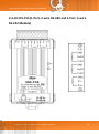
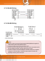
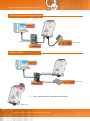
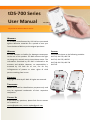
tDS-700 Series User Manual Ver.1.8.2 Tiny Serial-to-Ethernet Device Server WARRANTY All products manufactured by ICP DAS are warranted against defective materials for a period of one year from the date of delivery to the original purchaser. WARNING SUPPORT ICP DAS assumes no liability for damages consequent to the use of this product. ICP DAS reserves the right This manual relates to the following modules: tDS-712, tDS-722, tDS-732 to change this manual at any time without notice. The information furnished by ICP DAS is believed to be accurate and reliable. However, no responsibility is assumed by ICP DAS for its use, nor for any infringements of patents or other rights of third parties resulting from its use. tDS-715, tDS-725, tDS735 tDS-718, tDS-724, tDS-734 tDS-715i COPYRIGHT Copyright © 2014 by ICP DAS. All rights are reserved. TRADEMARKS Names are used for identification purposes only and may be registered trademarks of their respective companies. CONTACT US If you have any questions, please feel free to contact us via email at: [email protected], [email protected] Tiny Serial-to-Ethernet Device Server User Manual TABLE OF CONTENTS PACKING LIST................................................................................................................................................................ 5 MORE INFORMATION ................................................................................................................................................... 5 1. 2. INTRODUCTION ................................................................................................................................................... 6 1.1 ETHERNET SOLUTIONS ............................................................................................................................................. 8 1.2 VXCOMM TECHNOLOGY .......................................................................................................................................... 9 1.3 WEB SERVER TECHNOLOGY .................................................................................................................................... 11 HARDWARE INFORMATION ............................................................................................................................... 12 2.1 SPECIFICATIONS .................................................................................................................................................... 12 2.2 FEATURES ........................................................................................................................................................... 13 2.3 SELECTION GUIDE ................................................................................................................................................. 14 2.4 APPEARANCE ....................................................................................................................................................... 15 2.5 DIMENSIONS........................................................................................................................................................ 17 2.6 PIN ASSIGNMENTS ................................................................................................................................................ 19 2.6.1 tDS-712 (1-Port, 5-wire RS-232 Module) .......................................................................................................... 19 2.6.2 tDS-722 (2-Port, 5-wire RS-232 Module) .......................................................................................................... 20 2.6.3 tDS-732 (3-Port, 3-wire RS-232 Module) .......................................................................................................... 21 2.6.4 tDS-715 (1-Port, 2/4-wire RS-485/422 Module) ............................................................................................... 22 2.6.5 tDS-715i (1-Port Isolated 2/4-wire RS-485/422 Module) ................................................................................. 23 2.6.6 tDS-725 (2-Port, 2-wire RS-485 Module) .......................................................................................................... 24 2.6.7 tDS-735 (2-Port, 3-wire RS-485 Module) .......................................................................................................... 25 2.6.8 tDS-718 (1-Port, 3-wire RS-232 and 2/4-wire RS-485/422 Module) ................................................................. 26 2.6.9 tDS-724 (1-Port, 2-wire RS-485 and 1-Port, 5-wire RS-232 Module) ................................................................ 27 2.6.10 tDS-734 (1-Port, 2-wire RS-485 and 2-Port, 3-wire RS-232 Module) .............................................................. 28 2.7 WIRING NOTES FOR RS-232/485/422 INTERFACES .................................................................................................. 29 2.7.1 RS-232 Wiring ................................................................................................................................................... 29 2.7.2 RS-422 Wiring ................................................................................................................................................... 30 2.7.3 RS-485 Wiring ................................................................................................................................................... 30 3. SETTING UP THE TDS-700 MODULE ................................................................................................................... 31 4. WEB CONFIGURATION ....................................................................................................................................... 39 4.1 LOGGING IN TO THE TDS-700 WEB SERVER .............................................................................................................. 39 4.2 HOME PAGE ........................................................................................................................................................ 41 Copyright © 2014 ICP DAS CO., Ltd. All Rights Reserved. -2- Tiny Serial-to-Ethernet Device Server User Manual 4.3 NETWORK SETTING ............................................................................................................................................... 42 4.3.1 Network and Miscellaneous Settings .......................................................................................................... 42 4.3.2 IP Address Settings ...................................................................................................................................... 43 4.3.3 General Settings .......................................................................................................................................... 46 4.3.4 Restore Factory Defaults ............................................................................................................................. 48 4.3.5 Firmware Update ........................................................................................................................................ 50 4.4 SERIAL PORT PAGE................................................................................................................................................ 51 4.4.1 4.5 Port1 Settings .............................................................................................................................................. 51 FILTER PAGE ........................................................................................................................................................ 54 4.5.1 Accessible IP Settings (white list) ................................................................................................................ 54 4.6 MONITOR PAGE ................................................................................................................................................... 55 4.7 CHANGE PASSWORD ............................................................................................................................................. 56 4.8 LOGOUT PAGE ..................................................................................................................................................... 57 5. TYPICAL APPLICATIONS ..................................................................................................................................... 58 5.1 VIRTUAL COM APPLICATION .................................................................................................................................. 59 5.2 DIRECT SOCKET CONNECTION APPLICATIONS ............................................................................................................. 60 5.3 ETHERNET I/O APPLICATIONS ................................................................................................................................. 63 5.4 PAIR-CONNECTION APPLICATIONS ............................................................................................................................ 65 5.5 TCP CLIENT MODE APPLICATIONS ........................................................................................................................... 72 6. CGI CONFIGURATION ......................................................................................................................................... 80 6.1 CGI URL SYNTAX ................................................................................................................................................. 80 6.2 CGI COMMAND LIST ............................................................................................................................................. 81 APPENDIX A: GLOSSARY ............................................................................................................................................. 83 1. ARP (ADDRESS RESOLUTION PROTOCOL) ..................................................................................................................... 83 2. CLIENTS AND SERVERS ............................................................................................................................................... 83 3. ETHERNET ................................................................................................................................................................ 84 4. FIRMWARE .............................................................................................................................................................. 84 5. GATEWAY ................................................................................................................................................................ 84 6. ICMP (INTERNET CONTROL MESSAGE PROTOCOL) ......................................................................................................... 84 7. INTERNET ................................................................................................................................................................ 84 8. IP (INTERNET PROTOCOL) ADDRESS ............................................................................................................................. 85 9. MAC (MEDIA ACCESS CONTROL) ADDRESS .................................................................................................................. 85 10. PACKET .............................................................................................................................................................. 85 11. PING .................................................................................................................................................................. 85 12. RARP (REVERSE ADDRESS RESOLUTION PROTOCOL) ................................................................................................. 86 13. SOCKET .............................................................................................................................................................. 86 Copyright © 2014 ICP DAS CO., Ltd. All Rights Reserved. -3- Tiny Serial-to-Ethernet Device Server User Manual 14. SUBNET MASK ..................................................................................................................................................... 86 15. TCP (TRANSMISSION CONTROL PROTOCOL) ............................................................................................................. 86 16. TCP/IP .............................................................................................................................................................. 87 17. UDP (USER DATAGRAM PROTOCOL) ...................................................................................................................... 87 APPENDIX B: ACTUAL BAUD RATE MEASUREMENT .................................................................................................... 88 Copyright © 2014 ICP DAS CO., Ltd. All Rights Reserved. -4- Tiny Serial-to-Ethernet Device Server User Manual Packing List The shipping package includes the following items: Note: One tDS-700 series hardware module One printed Quick Start Guide One software utility CD Quick start If any of these items are missing or damaged, please contact the local distributor for more information. Save the shipping materials and cartons in case you need to ship the module in the future. More Information Documentation CD:\NAPDOS\tDS-700\Document http://ftp.icpdas.com/pub/cd/tinymodules/napdos/tds-700/document/ Firmware CD:\NAPDOS\tDS-700\Firmware http://ftp.icpdas.com/pub/cd/tinymodules/napdos/tds-700/firmware/ Software CD:\NAPDOS\Software http://ftp.icpdas.com/pub/cd/tinymodules/napdos/software/ Copyright © 2014 ICP DAS CO., Ltd. All Rights Reserved. -5- Tiny Serial-to-Ethernet Device Server User Manual 1. Introduction The tDS-700 is a series of Serial-to-Ethernet device servers that are designed to add Ethernet and Internet connectivity to any RS-232 and RS-422/485 device, and to eliminate the cable length limitation of legacy serial communications. By using the VxComm Driver/Utility, the built-in COM Port of the tDS-700 series can be virtualized to a standard PC COM Port in Windows. Therefore, users can transparently access or monitor serial devices over the Internet/Ethernet without the need for software modification. tDS-700 device servers can be used to create a pair-connection application (as well as serial-bridge or serial-tunnel), and then route data between two serial devices via TCP/IP. This is useful when connecting mainframe computers, servers or other serial devices that do not themselves have Ethernet capability. By virtue of its protocol independence and flexibility, the tDS-700 meets the demands of virtually any network-enabled application. Copyright © 2014 ICP DAS CO., Ltd. All Rights Reserved. -6- Tiny Serial-to-Ethernet Device Server User Manual In harsh industrial environments, the tDS-700 series (for i version) also adds 2500 VDC and +/- 4 kV ESD protection component that diverts the potentially damaging charge away from sensitive circuit to protects the module and equipment from the sudden and momentary electric current. To achieve maximum space savings, the tDS-700 is offered in an amazingly small form-factor that enables it to be easily installed anywhere, even directly attached to a serial device or embedded into a machine. The tDS-700 features a powerful 32-bit MCU that allows it to efficiently handle network traffic. The tDS-700 offers true IEEE 802.3af-compliant (classification, Class 1) Power-overEthernet (PoE) functionality using a standard category 5 Ethernet cable that allows it to receive power from a PoE switch such as the NS-205PSE. If there is no PoE switch available on site, the tDS700 can accepts power input from a DC adapter. Comparison of Device Servers: Series PPDS PDS DS tDS tGW Virtual COM Yes Yes Yes Yes - Programmable Yes Yes - - - PoE Yes - - Yes Yes Modbus Gateway Yes - - - Yes 1 Sockets/Port 10 Sockets/Port Cost-effective, Entry-level Cost-effective, Entry-level Features Multi-client Remarks About 20 Sockets Professional Powerful Isolation for DS-715 Copyright © 2014 ICP DAS CO., Ltd. All Rights Reserved. -7- Tiny Serial-to-Ethernet Device Server User Manual 1.1 Ethernet Solutions Nowadays, the Ethernet protocol has become the foremost standard for local area networks. Connectivity via the Internet is now common in many of the latest applications from home appliances, to vending machines, to testing equipment, to UPS, etc. An Ethernet network can link office automation and industrial control networks, access remote systems and share data and information between machines from multiple vendors, and also provides a cost-effective solution for industrial control networks. Copyright © 2014 ICP DAS CO., Ltd. All Rights Reserved. -8- Tiny Serial-to-Ethernet Device Server User Manual 1.2 VxComm Technology In general, writing a TCP/IP program is more difficult than writing a COM Port program. Another issue is that perhaps the existing the COM Port communication system was built many years ago and is now outdated. As a result, a new technology, VxComm was developed to virtualize the COM Ports of the tDS-700 to allow up to 256 COM Ports to be used on a central computer. The VxComm driver saves time when accessing serial devices through the Ethernet without the need for reprogramming the COM Port software on the PC. Copyright © 2014 ICP DAS CO., Ltd. All Rights Reserved. -9- Tiny Serial-to-Ethernet Device Server User Manual The VxComm driver controls all the details of the Ethernet TCP/IP programming technique, meaning that, with the assistance of tDS-700 and VxComm technology, your COM Port program will be able to access your serial devices through the Ethernet in the same way as through a COM Port. Copyright © 2014 ICP DAS CO., Ltd. All Rights Reserved. - 10 - Tiny Serial-to-Ethernet Device Server User Manual 1.3 Web Server Technology Web server technology enables the tDS-700 to be configured via a standard web browser interface, e.g. Google Chrome, Internet Explorer, or Firefox, etc. This means that it is easy to check the configuration of the tDS-700 via an Ethernet network without needing to install any other software tools, thereby reducing the learning curve required for maintaining the device. Copyright © 2014 ICP DAS CO., Ltd. All Rights Reserved. - 11 - Tiny Serial-to-Ethernet Device Server User Manual 2. Hardware Information This chapter provides a detailed description of the front panel, the hardware specifications, the pin assignments, the wiring notes and the dimensions for the tDS-700 series modules. 2.1 Specifications Model tDS-712 tDS-722 tDS-732 tDS-715 tDS-715i tDS-725 tDS-735 tDS-718 tDS-724 tDS-734 3-wire RS-232 2-wire RS-485 4-wire RS-422 2-wire RS-485 2-wire RS-485 - 5-wire RS-232 - - 3-wire RS-232 3-wire RS-232 System CPU 32-bit ARM Communication Interface 10/100 Base-TX, 8-pin RJ-45 x 1, (Auto-negotiating, Auto-MDI/MDIX, LED indicator) PoE (IEEE 802.3af, Class 1) Ethernet COM1 COM2 COM3 Self-Tuner RS485 5-wire RS-232 5-wire RS-232 3-wire RS-232 2-wire RS-485 4-wire RS-422 2-wire RS-485 2-wire RS-485 - 5-wire RS-232 - 2-wire RS-485 - - 3-wire RS-232 3-wire RS-232 - - 2-wire RS-485 2-wire RS-485 - Yes, automatic RS-485 direction control Bias Resistor - Yes, 1 KΩ Node - 254 (max.) UART 16c550 or compatible Isolation - ESD Protection - - - 2500 VDC +/-4 kV - - - - - COM Port Format Baud Rate 115200 bps Max. Data Bit 5, 6, 7, 8 Parity None, Odd, Even, Mark, Space Stop Bit 1, 2 Power Power Input PoE: IEEE 802.3af, Class 1 DC jack: +12 ~ 48 VDC Power Consumption 0.07 A @ 24 VDC Mechanism Connector Male DB-9 x1 Mounting DIN-Rail Flammability Fire Retardant Materials (UL94-V0 Level) 10-Pin Removable Terminal Block x 1 Environment Operating Temperature -25 ~ +75 °C Storage Temperature -30 ~ +80 °C Humidity 10 ~ 90% RH, non-condensing Note: COM1/COM2/COM3 = TCP Port 10001/10002/10003 Copyright © 2014 ICP DAS CO., Ltd. All Rights Reserved. - 12 - Tiny Serial-to-Ethernet Device Server User Manual 2.2 Features Incorporates any RS-232/422/485 serial device in Ethernet Data transmission via Virtual COM or raw TCP connection VxComm Driver for 32-bit and 64-bit Windows XP/2003/2008/Vista/7/8/10 Max. connections: 1 socket per serial port is suggested Supports pair-connection (serial-bridge, serial-tunnel) applications Supports TCP client-mode and TCP server-mode operations Supports UDP responder for device discovery (UDP Search) Static IP or DHCP network configuration Easy firmware update via the Ethernet (BOOTP, TFTP) Tiny Web server for configuration (HTTP) Contains a 32-bit MCU that efficiently handles network traffic 10/100 Base-TX Ethernet, RJ-45 x1 (Auto-negotiating, auto MDI/MDIX, LED Indicators) Includes redundant power inputs: PoE (IEEE 802.3af, Class 1) and DC jack Allows automatic RS-485 direction control 2500 VDC isolation and +/- 4 kV ESD protection for i versions Male DB-9 or terminal block connector for easy wiring Tiny form-factor and low power consumption RoHS compliant with no Halogen Cost-effective device servers Copyright © 2014 ICP DAS CO., Ltd. All Rights Reserved. - 13 - Tiny Serial-to-Ethernet Device Server User Manual 2.3 Selection Guide Model CPU Ethernet Baud Rate COM1 COM2 COM3 tDS-712 5-wire RS-232 - - tDS-722 5-wire RS-232 5-wire RS-232 - tDS-732 3-wire RS-232 3-wire RS-232 3-wire RS-232 - - - - 2-wire RS-485 2-wire RS-485 - 2-wire RS-485 2-wire RS-485 2-wire RS-485 - - 2-wire RS-485 tDS-715 4-wire RS-422 Isolated tDS-715i tDS-725 32-bit 10/100 Base-TX, 115200 MCU PoE bps tDS-735 2-wire RS-485 4-wire RS-422 3-wire RS-232 tDS-718 2-wire RS-485 4-wire RS-422 tDS-724 2-wire RS-485 5-wire RS-232 - tDS-734 2-wire RS-485 3-wire RS-232 3-wire RS-232 3-Wire RS-232: RxD, TxD, GND (Non-isolated) 5-Wire RS-232: RxD, TxD, CTS, RTS, GND (No-isolated) 2-Wire RS-485: DATA+, DATA-, GND (Non-isolated) 4-Wire RS-422: TxD+, TxD-, RxD+, RxD-, GND (Non-islated) Copyright © 2014 ICP DAS CO., Ltd. All Rights Reserved. - 14 - Tiny Serial-to-Ethernet Device Server User Manual 2.4 Appearance Front View 1. Robust Insulated and Fire-retardant Case 2. Serial COM Ports The number of serial COM Ports available depends on the type of tDS-700 module. For more detailed information regarding 2 the pin assignments for the Serial COM ports, refer to Section 2.6 Pin Assignments. 1 3 3. S1: System LED indicator Once power is supplied to the tDS-700 module, the system LED indicator will illuminate. An overview of the LED functions is given below: 4 6 5 Function System LED Behavior Running Firmware Steady ON Network Ready Serial Port Busy 4. Slow flashing – Once every 3 seconds Rapid flashing – Once every 0.2 seconds Operating Mode Switch Init Mode: Configuration mode Run Mode: Firmware operation mode For tDS-700 series modules, the operating mode switch is set to the Run position by default. In order to update the firmware for the tDS-700 module, the switch must be moved from the Run position to the Init position. The switch must be returned to the Run position after the update is complete. Copyright © 2014 ICP DAS CO., Ltd. All Rights Reserved. - 15 - Tiny Serial-to-Ethernet Device Server User Manual 5. +12 to +48 VDC Jack: The tDS-700 is equipped with a +12 VDC to +48 VDC jack that can be used to connect a power supply. If no PoE switch is available on site, a DC adapter can be used to power the tDS-700 module. 6. PoE and Ethernet RJ-45 Jack The tDS-700 module is equipped with an RJ-45 jack that is used as the 10/100 Base-TX Ethernet port and features networking capabilities. When an Ethernet link is detected and an Ethernet packet is received, the Link/Act LED (Orange) indicator will be illuminated. When power is supplied via PoE (Power-overEthernet), the PoE LED (Green) indicator will be illuminated. Copyright © 2014 ICP DAS CO., Ltd. All Rights Reserved. - 16 - Tiny Serial-to-Ethernet Device Server User Manual 2.5 Dimensions tDS-712: Units: mm Rear View Front View Top View Left Side View Right Side View Copyright © 2014 ICP DAS CO., Ltd. All Rights Reserved. Bottom View - 17 - Tiny Serial-to-Ethernet Device Server User Manual tDS-722/732/715/715i/725/735/718/724/734 : Units: mm Front View Rear View Top View Left Side View Right Side View Copyright © 2014 ICP DAS CO., Ltd. All Rights Reserved. Bottom View - 18 - Tiny Serial-to-Ethernet Device Server User Manual 2.6 Pin Assignments 2.6.1 tDS-712 (1-Port, 5-wire RS-232 Module) Copyright © 2014 ICP DAS CO., Ltd. All Rights Reserved. - 19 - Tiny Serial-to-Ethernet Device Server User Manual 2.6.2 tDS-722 (2-Port, 5-wire RS-232 Module) Copyright © 2014 ICP DAS CO., Ltd. All Rights Reserved. - 20 - Tiny Serial-to-Ethernet Device Server User Manual 2.6.3 tDS-732 (3-Port, 3-wire RS-232 Module) Copyright © 2014 ICP DAS CO., Ltd. All Rights Reserved. - 21 - Tiny Serial-to-Ethernet Device Server User Manual 2.6.4 tDS-715 (1-Port, 2/4-wire RS-485/422 Module) Copyright © 2014 ICP DAS CO., Ltd. All Rights Reserved. - 22 - Tiny Serial-to-Ethernet Device Server User Manual 2.6.5 tDS-715i (1-Port Isolated 2/4-wire RS-485/422 Module) Copyright © 2014 ICP DAS CO., Ltd. All Rights Reserved. - 23 - Tiny Serial-to-Ethernet Device Server User Manual 2.6.6 tDS-725 (2-Port, 2-wire RS-485 Module) Copyright © 2014 ICP DAS CO., Ltd. All Rights Reserved. - 24 - Tiny Serial-to-Ethernet Device Server User Manual 2.6.7 tDS-735 (2-Port, 3-wire RS-485 Module) Copyright © 2014 ICP DAS CO., Ltd. All Rights Reserved. - 25 - Tiny Serial-to-Ethernet Device Server User Manual 2.6.8 tDS-718 (1-Port, 3-wire RS-232 and 2/4-wire RS485/422 Module) Copyright © 2014 ICP DAS CO., Ltd. All Rights Reserved. - 26 - Tiny Serial-to-Ethernet Device Server User Manual 2.6.9 tDS-724 (1-Port, 2-wire RS-485 and 1-Port, 5-wire RS232 Module) Copyright © 2014 ICP DAS CO., Ltd. All Rights Reserved. - 27 - Tiny Serial-to-Ethernet Device Server User Manual 2.6.10 tDS-734 (1-Port, 2-wire RS-485 and 2-Port, 3-wire RS-232 Module) Copyright © 2014 ICP DAS CO., Ltd. All Rights Reserved. - 28 - Tiny Serial-to-Ethernet Device Server User Manual 2.7 Wiring Notes for RS-232/485/422 Interfaces 2.7.1 RS-232 Wiring Note: FGND is the frame ground that is soldered to the metal shield on the DB-9 cable. Copyright © 2014 ICP DAS CO., Ltd. All Rights Reserved. - 29 - Tiny Serial-to-Ethernet Device Server User Manual 2.7.2 RS-422 Wiring 2.7.3 RS-485 Wiring Note: 1. Usually, you have to connect all signal grounds of RS-422/485 devices together to reduce common-mode voltage between devices. 2. Twisted-pair cable must be used for the DATA+/- wires. 3. Both two ends of the cable may require a termination resistor connected across the two wires (DATA+ and DATA-). Typically 120 Ω resisters are used. 4. The Data+ and B pins are positive-voltage pins, and Data- and A pins are negativevoltage pins in the above figure. The B/A pins may be defined in another way depending on devices, please check it first. Copyright © 2014 ICP DAS CO., Ltd. All Rights Reserved. - 30 - Tiny Serial-to-Ethernet Device Server User Manual 3. Setting up the tDS-700 Module This chapter provides detailed information about the “Self-Test” process, which is used to confirm that the tDS-700 series module is operating correctly. Before beginning the “Self-Test” process, the wiring test, Ethernet configuration and VxComm utility driver installation procedures must first be fully completed. Follow the procedure described below: Step 1: Connect the Power Supply and the Host PC 1. Ensure that the network settings on your PC are configured correctly. 2. Ensure that the Windows firewall or any Anti-Virus firewall software is correctly configured or temporarily disable these functions; otherwise the “Search Servers” function in the eSearch Utility may not work as required. You may need to contact your System Administrator for more details of how to do this. 3. Check that the Init/Run switch is in the “Run” position. Figure 3-1 4. Connect both the tDS-700 and the Host computer to the same sub-network or the same Ethernet Switch, and then power on the tDS-700. Refer to Figures 3-2 and 3-3 for illustrations of how to do this. Copyright © 2014 ICP DAS CO., Ltd. All Rights Reserved. - 31 - Tiny Serial-to-Ethernet Device Server User Manual +12 to +48 VDC jack Power Supply (Non-PoE) Figure 3-2 PoE Power Supply Figure 3-3 5. Verify that the System LED indicator is flashing. Figure 3-4 Copyright © 2014 ICP DAS CO., Ltd. All Rights Reserved. - 32 - Tiny Serial-to-Ethernet Device Server User Manual 6. Perform a Self-test wiring check as follows: RS-232 Wiring of COM1: RS-422 Wiring of COM1: Copyright © 2014 ICP DAS CO., Ltd. All Rights Reserved. - 33 - Tiny Serial-to-Ethernet Device Server User Manual Step 2: Install the VxComm Utility The VxComm Utility can be obtained from either the companion CD-ROM, the ICP DAS FTP site, or the ICP DAS web site. The location of the install files on the CD and the download addresses are shown below: CD:\\ NAPDOS\Software\VxComm_Driver\ http://ftp.icpdas.com/pub/cd/tinymodules/napdos/software/vxcomm_dr iver/ Step 3: Search for the tDS-700 series module on the Ethernet network 1. Open the VxComm Utility and then click the “Search Servers” button to search for the tDS-700 module. 2. Once the search process is complete, double-click the name of the tDS-700 module to open the “Configure Server” dialog box. 2 1 Copyright © 2014 ICP DAS CO., Ltd. All Rights Reserved. - 34 - Tiny Serial-to-Ethernet Device Server User Manual 3. Enter the network settings information, including the IP, Mask and Gateway addresses, and then click “OK” button. The new settings for the tDS-700 will take effect within 2 seconds. If you don’t know the correct network configuration information, contact your Network Administrator to obtain the details. 1 2 Step 4: Configuring the Virtual COM Ports 1. Wait 2 seconds and then click the “Search Servers” button again to ensure that the tDS-700 is working correctly with the new configuration. 1 2. Click your tDS-700 in the list Copyright © 2014 ICP DAS CO., Ltd. All Rights Reserved. - 35 - Tiny Serial-to-Ethernet Device Server User Manual 2. Click the “Add Server[s]” button. Assign a COM Port number and click “OK” to save your settings. 3 4. Assign a COM Port number 5 3. Click on tDS-700 name and check the virtual COM port mappings on the PC. 6. Check the COM Port Copyright © 2014 ICP DAS CO., Ltd. All Rights Reserved. - 36 - Tiny Serial-to-Ethernet Device Server User Manual 4. Click “Tools” “Restart Driver”, and then click the “Restart Driver” button. 7 8 Step 5: Testing your tDS-700 1. Right click Port 1 and then choose the “Open COM Port” item. 2. Check that the configuration of the COM Port is correct and then click the “Open COM” button. 2. Right Click 1. Click 3 Copyright © 2014 ICP DAS CO., Ltd. All Rights Reserved. - 37 - Tiny Serial-to-Ethernet Device Server User Manual 3. Type a string in the send field then click the “Send” button. If a response is received, it will be displayed in the received field. Complete 4 5. Response Message 4. If the test is successful, then your COM port program should now be able to work with this Virtual COM Port. Note: While using RS-485 modules (Ex, tDS-725), you should wire the Data1+ and Data2+ signals, and wire the Data1- and Data2- signals when performing a self-test. Open the first two COM Ports and use one to send data to and the other to receive data. Copyright © 2014 ICP DAS CO., Ltd. All Rights Reserved. - 38 - Tiny Serial-to-Ethernet Device Server User Manual 4. Web Configuration Once the tDS-700 module has been correctly configured and is functioning on the network normally, the configuration details can be retrieved or modified using either the VxComm Utility or a standard web browser. 4.1 Logging in to the tDS-700 Web Server The embedded tDS-700 series web server can be accessed from any computer that has an Internet connection. Step 1: Open a new browser window. Open a web browser, for example, Google Chrome, Firefox or Internet Explorer, which are reliable and popular Internet browsers that can be used to configure tDS-700 series module. Note that if you intend to use Internet Explorer, ensure that the cache function is disabled in order to prevent browser access errors. Detailed instructions for how to do this can be found in “FAQ: How to avoid a browser access error that causes a blank page to be displayed when using Internet Explorer”. Step 2: Enter the URL for the tDS-700 web server Ensure that you have correctly configured the network settings for the tDS-700 series module (refer to Chapter 3 Setting up the tDS-700 module for detailed instructions), and then enter the URL for the tDS-700 web server in the address bar of the browser. Copyright © 2014 ICP DAS CO., Ltd. All Rights Reserved. - 39 - Tiny Serial-to-Ethernet Device Server User Manual Step 3: Enter the Password After the main login page is displayed, enter a password (the factory default password is “admin”), and then click the “Submit” button to continue. Factory Default Password: admin Step 4: Log in to the tDS-700 Web Server After logging into the tDS-700 web server, the main page will be displayed. Copyright © 2014 ICP DAS CO., Ltd. All Rights Reserved. - 40 - Tiny Serial-to-Ethernet Device Server User Manual 4.2 Home Page The Home link connects to the main page, which contains two parts. The first part of this page provides basic information about the tDS-700 hardware and software. The second part of this page provides the status of the port settings and pairconnection settings. Copyright © 2014 ICP DAS CO., Ltd. All Rights Reserved. - 41 - Tiny Serial-to-Ethernet Device Server User Manual 4.3 Network Setting 4.3.1 Network and Miscellaneous Settings The Network and Miscellaneous Settings page provides basic details of the tDS-700 module and other information related to the hardware and software. The software and hardware information section includes information related to the Model Name, the current Firmware version, the IP Address, the current position of the Initial Switch, the Alias, the MAC Address, and the TCP Port, and the System Timeout values. If you update the firmware for the tDS-700 module, this page can be used to check the version information of the tDS-700 software. Copyright © 2014 ICP DAS CO., Ltd. All Rights Reserved. - 42 - Tiny Serial-to-Ethernet Device Server User Manual 4.3.2 IP Address Settings The Address Type, Static IP Address, Subnet Mask and Default Gateway values are the most important network settings and should always correspond to the LAN configuration. If they do not match, the tDS-700 module will not operate correctly. If the settings are changed while the module is operating, any connection currently in use will be lost and an error will occur. The following is an overview of the parameters contained in the IP Address Settings section: Item Description IP Address Static IP: If no DHCP server is installed on the network, the network settings can be configured manually. Refer to Section 4.3.2.1 Manual Configuration for more details. Address Type DHCP: The Dynamic Host Configuration Protocol (DHCP) is a network application protocol that automatically assigns an IP address to each device. Refer to Section 4.3.2.2 Dynamic Configuration for more details. Static IP Address Each tDS-700 connected to the network must have its own unique IP address. This parameter is used to assign a specific IP address. Copyright © 2014 ICP DAS CO., Ltd. All Rights Reserved. - 43 - Tiny Serial-to-Ethernet Device Server User Manual Item Description Subnet Mask This parameter is used to assign the subnet mask for the tDS-700 device. The subnet mask indicates which portion of the IP address is used to identify the local network or subnet. Default Gateway This parameter is used to assign the IP Address of the Gateway to be used by the tDS-700. A Gateway (or router) is a device that is used to connect an individual network to one or more additional networks. MAC Address This parameter is used to set a user-defined MAC address, which must be in the format FF-FF-FF-FF-FF-FF. Virtual COM TCP Command Port This parameter is used to configure the TCP Command Port to a custom value depending on your requirement. Note that if the TCP Command Port configuration setting is completed, the TCP port of serial port will be change, as follows: COM1= TCP Command Port + 1 COM2= TCP Command Port + 2 The default TCP Command Port is 10000, Thus, the serial COM port1/port2 is 10001/10002, and so on. Command Port Timeout (Socket Watchdog) If the command port does not receive any data from the TCP/IP socket for a certain period, the tDS-700 can disconnect the socket. Settings range value: 1 ~ 65535 (seconds); Default value: 30 (seconds); Disabled: 0; Update Settings Click this button to save the revised settings to the tDS-700. 4.3.2.1 Manual Configuration When using manual configuration, the network settings should be assigned in the following manner: Step 1: Select the “Static IP” option from the “Address Type” drop-down menu. Step 2: Enter the relevant details in the respective network settings fields. Step 3: Click the “Update Settings” button to complete the configuration. ※ Refer to Figure 4-1 for an illustration of how to perform the above procedure. Copyright © 2014 ICP DAS CO., Ltd. All Rights Reserved. - 44 - Tiny Serial-to-Ethernet Device Server User Manual 1 2 3 Figure 4-1 4.3.2.2 Dynamic Configuration Dynamic configuration is very easy to perform. If a DHCP server is connected to you network, a network address can be dynamically configured by using the following procedure: Step 1: Select the “DHCP” option from the “Address Type” drop-down menu. Step 2: Click the “Update Settings” button to complete the configuration. 1 2 Figure 4-2 Copyright © 2014 ICP DAS CO., Ltd. All Rights Reserved. - 45 - Tiny Serial-to-Ethernet Device Server User Manual 4.3.3 General Settings The General Settings provides functions allowing items such as the Alias Name, System Timeout value, UART Watchdog value, Auto-logout value, Debug Message and CGI Configuration to be configured. The following is an overview of the parameters contained in the General Settings section: Item Description Default Network Ethernet Speed System Timeout (Network Watchdog) This parameter is used to set the Ethernet speed. The default value is Auto (Auto = 10/100 Mbps Autonegotiation). This parameter is used to configure the system timeout value. If there is no activity on the network for a specific period of time, the system will be rebooted based on the configured system timeout value. Auto 300 Timeout value range: 30 to 65535 (seconds); Disable = 0. Copyright © 2014 ICP DAS CO., Ltd. All Rights Reserved. - 46 - Tiny Serial-to-Ethernet Device Server User Manual Item Description Web Auto-logout This parameter is used to configure the automatic logout value. If there is no activity on the web server for a certain period of time, the current user account will be automatically logged out. 10 CGI Configuration Range: 1 to 65535 (minutes); Disable = 0. The tDS-700 can be configured by CGI command. For detailed CGI command and configuration information, refer to Chapter 6 “CGI Configuration” Enable Default Enable/Disable the assign.cgi. UDP Configuration This parameter is used to enable or disable UDP configuration function. Enable UDP Alarm Alarm IP Address (UDP) Alarm Port (UDP) The tDS-700 can send and UDP package (include alarm message) to specified network location (Alarm IP Address/Port). Misc. Alias Name UART Watchdog This parameter is used to assign an alias for each tDS-700 device to assist with easy identification. If the serial port does not communication occurs for a certain period, the system will be rebooted based on the UART Watchdog value. Tiny 0 Settings range: 30 ~ 65535 (seconds); Disable: 0. Debug Message(UDP) Reserved. Update Settings Click this button to save the revised settings to the tDS-700 device. Copyright © 2014 ICP DAS CO., Ltd. All Rights Reserved. 20 - 47 - Tiny Serial-to-Ethernet Device Server User Manual 4.3.4 Restore Factory Defaults Use the following procedure to reset all parameters to their original factory default settings: Step 1: Click the “Restore Defaults” button to reset the configuration. Step 2: Click the “OK” button in the message dialog box. Step 3: Check whether the module has been reset to the original factory default settings for use with the VxComm Utility. Refer to Chapter 3 Setting up the tDS-700 Module for more details. 1 2 3 The following is an overview of the factory default settings: Factory Default Settings Network Settings IP Address 192.168.255.1 Gateway Address 192.168.0.1 Subnet Mask 255.255.0.0 DHCP Disabled Basic Settings Alias Tiny Copyright © 2014 ICP DAS CO., Ltd. All Rights Reserved. - 48 - Tiny Serial-to-Ethernet Device Server User Manual The Forced Reboot function: can be used to force the tDS-700 to reboot or to remotely reboot the device. After the tDS-700 module has rebooted, the original login screen will be displayed requesting that you enter your Login Password before continuing. 1 2 Copyright © 2014 ICP DAS CO., Ltd. All Rights Reserved. - 49 - Tiny Serial-to-Ethernet Device Server User Manual 4.3.5 Firmware Update The Firmware update function is only supported by the firmware version is v1.3.8 [Sep.30, 2014] or later that can be not need to manually adjust the Init/Run Switch and reboot the tDS-700 to update the firmware. For detailed information regarding how to use this function to update the Firmware for your tDS700 series module, refer to the tDS_Firmware_v138_and_later_Update_vxxx_en.pdf. The location of the user manual on the CD and the download address are shown below: CD:\\ NAPDOS\tDS-700\Firmware\ http://ftp.icpdas.com/pub/cd/tinymodules/napdos/tds-700/firmware/ Copyright © 2014 ICP DAS CO., Ltd. All Rights Reserved. - 50 - Tiny Serial-to-Ethernet Device Server User Manual 4.4 Serial Port Page The Port 1 Settings section provides basic information related to the hardware and software for the tDS-700 series module, including the Firmware version and the IP Address, etc. and then provides functions allowing items such as port settings, serial data packing and pair-connection settings to be configured. 4.4.1 Port1 Settings Copyright © 2014 ICP DAS CO., Ltd. All Rights Reserved. - 51 - Tiny Serial-to-Ethernet Device Server User Manual The following is an overview of the parameters contained in the Port1 Settings section: Item Description Default Port Settings Baud Rate (bps) Data Size (bits) Parity Stop Bits (bits) Flow Control Allow Driver Control (Original Name: Dynamic Serial Setting) Operation Mode Local TCP Port Connection Idle (seconds) (Original Name: TCP Timeout) This parameter is used to set the Baud Rate for the COM ports. This parameter is used to set the Data Size for the COM ports. This parameter is used to set the Parity for the COM ports. This parameter is used to set the Stop Bits for the COM ports. This parameter is used to set the Flow Control for the COM ports. Enable client (VxComm Driver) to dynamically change the data format and baud rate settings. M0/Multi-echo: Share received serial data between clients. M1/Single-echo: Send received serial data to the requested client only. 0 = Data-sharing; 1 = Non-sharing TCP Command Port +1 Note: COM1/COM2/COM3 = TCP port 10001/10002/10003 If the Local TCP port does not receive any data via the TCP/IP for a certain period, the tDS-700 will disconnect the socket based on the TCP timeout value. 115200 8 None 1 None Enable 0 10001 180 Settings range: 1 ~ 65535 (seconds); Disabled: 0; Serial Data Packing Slave Timeout (ms) Set the waiting time after last Tx of the request sent to the device. If the device does not respond within the timeout value, the tDS-700 will return existing data via TCP package and process next request. Copyright © 2014 ICP DAS CO., Ltd. All Rights Reserved. 1000 - 52 - Tiny Serial-to-Ethernet Device Server User Manual Item Description Default When the input serial data length reaches to the value, it will be sent out. Packing Length (bytes) Serial Ending Chars (Number[,char1][,char2]) Timeout Between Chars (ms) 0 Settings range: 0 ~ 1024; Disabled: 0. The tDS-700 outputs an Ethernet packet immediately after the ending-chars pattern is identified from the incoming serial data. The number of ending-chars can be 0 (disabled), 1 or 2 chars. Disabled=0; 1 char: 1,0x0D; 2 chars: 2,0x0D, 0x0A Set the waiting time after Rx of the response sent from the device. If the device does not respond within the timeout value, the tDS-700 will process this response. 0 10 Settings range: 10 ~ 65535; Disabled: 0. Pair-Connection Settings (Client/Server Mode) Application Mode Server Client Remote Server IP - IP address of the remote device Remote TCP Port - TCP Port number of the remote device (Original Name: Server Mode) Submit Click this button to save the revised settings to the tDS-700. Note: The more detailed information regarding pair-connection applications settings, please refer to the section 5.4 “Pair-Connection Applications". Copyright © 2014 ICP DAS CO., Ltd. All Rights Reserved. - 53 - Tiny Serial-to-Ethernet Device Server User Manual 4.5 Filter Page 4.5.1 Accessible IP Settings (white list) The Accessible IP Settings section is used to query or edit the IP Filter List. The IP Filter List restricts the access of packets based on the IP header. If one or more IP address are saved to the IP Filter table, only clients whose IP is specified in the IP Filter List can access the tDS-700. The following is an overview of the parameters contained in the Filter Settings (white list) section: Item Description Add “IP” To The List Add an IP address to the IP Filter List. Add Range “IP”& Mask “IP” Add an IP address range to the IP Filter List. Delete IP# “Number” Delete a specific IP# address from the IP Filter List. (Number: 0 ~ 4) Delete All Delete all items from the IP Filter List. Save Configuration (finish) Save a new IP Filter List to the Flash memory. Submit Click this button to save the revised settings to the tDS-700. Copyright © 2014 ICP DAS CO., Ltd. All Rights Reserved. - 54 - Tiny Serial-to-Ethernet Device Server User Manual 4.6 Monitor Page After clicking the Monitor tab, the Current Connection Status page will be displayed showing detailed information regarding the current status of the serial port connection settings for the tDS700 module. Copyright © 2014 ICP DAS CO., Ltd. All Rights Reserved. - 55 - Tiny Serial-to-Ethernet Device Server User Manual 4.7 Change Password After clicking the Password tab, the Change Password page will be displayed. To change a password, first enter the old password in the “Current password” field (use the default password “admin”) and then enter a new password in the “New password” field. Re-enter the new password in the “Confirm new password” field, and then click the “Submit” button to update the password. Copyright © 2014 ICP DAS CO., Ltd. All Rights Reserved. - 56 - Tiny Serial-to-Ethernet Device Server User Manual 4.8 Logout Page After clicking the Logout tab, you will be immediately logged out from the system and be returned to the login page. Copyright © 2014 ICP DAS CO., Ltd. All Rights Reserved. - 57 - Tiny Serial-to-Ethernet Device Server User Manual 5. Typical Applications This chapter provides some examples of typical scenarios for the tDS-700 module, including applications focused on the Virtual COM, Direct Socket Connection, Ethernet I/O, Pair-connection and TCP Client Mode, etc.. Copyright © 2014 ICP DAS CO., Ltd. All Rights Reserved. - 58 - Tiny Serial-to-Ethernet Device Server User Manual 5.1 Virtual COM Application The tDS-700 series is designed to link RS-232/422/485 devices to an Ethernet network. The VxComm utility allows the built-in tDS-700 COM Port to be virtualized to a standard COM Port of a host PC, as shown below: In the configuration above, Meter-1 is virtualized to link to COM3 of the host PC. Therefore, a program originally designed for the MS-COMM standard can access the meter without the need for any modification. Copyright © 2014 ICP DAS CO., Ltd. All Rights Reserved. - 59 - Tiny Serial-to-Ethernet Device Server User Manual 5.2 Direct Socket Connection Applications tDS-700 series module can accept the TCP connection (include raw data) directly, it also can communicate with TCP client and Serial Device in this way. For examples of socket connection test as follows: Copyright © 2014 ICP DAS CO., Ltd. All Rights Reserved. - 60 - Tiny Serial-to-Ethernet Device Server User Manual 1. Confirm that the tDS-700 modules are functioning correctly. Refer to Chapter 3 Setting up the tDS-700 module for more details. 2. Wire the slave device (Ex: M-7015, optional) with your tDS-700. For detailed RS-422/485 wiring information, refer to section 2.7 “Wiring Notes for RS-232/485/422 Interfaces”. 3. Supply power to the slave device (Ex, M-7015, Device ID: 2, +10~+30 VDC power used.) 4. Install VxComm utility, and then configuration Ethernet setting (such as IP/Mask/Gateway details) for tDS-700 series module; refer to Chapter 3 Setting up the tDS-700 module. 5. Confirm the serial port settings (baud Rate and data format) must be the same between the tDS-700 and slave device (M-7015). For example: Port Settings Model TCP Port Baud Rate Data Format tDS-700 9600 8,N,1 10001 Slave Device (M-7015) 9600 8,N,1 - 6. Right click in the “Configure Port” area and then choose the “Open TCP Port” item under the VxComm utility. Copyright © 2014 ICP DAS CO., Ltd. All Rights Reserved. - 61 - Tiny Serial-to-Ethernet Device Server User Manual 7. Type the IP address of tDS-700 in the IP Address field and assign a TCP/IP port of tDS-700, and then click the “Open TCP” button. 8. Type a string in the send field then click the “Send” button. If a response is received, it will be displayed in the received field. Response Message Complete Copyright © 2014 ICP DAS CO., Ltd. All Rights Reserved. - 62 - Tiny Serial-to-Ethernet Device Server User Manual 5.3 Ethernet I/O Applications Linking to I-7000 series modules The I-7000 series provides a variety of I/O operations, such as D/I, D/O, A/D, D/A, Counter and Frequency Measurement, etc. The I-7000 series was originally designed to be used with RS-485 networks, so the RS-485 of COM on the tDS-700 can be used to link to I-7000 series modules. By using VxComm technology, programs that support serial devices on the host PC can be upgraded from an RS-485 network to an Ethernet network without requiring any modifications to the program. Configurable Ethernet Data Logger Using the VxComm driver, the tDS-700 + 7000 modules can be virtualized to become COM Port + 7000 modules located on the host PC, and then the Data Logger in the DCON Utility can be used to access data related to the I-7000 from the Ethernet. Signal data originating from the I-7000 modules can be analyzed using MS Excel without the need to write any custom programs. 1: The DCON utility includes a log function, as show below: Copyright © 2014 ICP DAS CO., Ltd. All Rights Reserved. - 63 - Tiny Serial-to-Ethernet Device Server User Manual 2: Configure the system connection as shown below and click the “Start” button to begin logging data. 3: Open the log file in MS Excel to view the log data as shown in the example below: By using the I-7000 DCON utility and MS Excel in conjunction with VxComm technology, the signal data originating from I-7000 modules via the Ethernet network can be analyzed without the need to write custom programs. For more information about the log function, refer to the online help feature (English and Traditional Chinese) of the DCON utility. Copyright © 2014 ICP DAS CO., Ltd. All Rights Reserved. - 64 - Tiny Serial-to-Ethernet Device Server User Manual 5.4 Pair-connection Applications tDS-700 device servers can be used to create a pair-connection application (as well as serial-bridge or serial-tunnel), and then route data between two serial devices via TCP/IP, which is useful when connecting mainframe computers, servers or other serial devices that do not themselves have Ethernet capability. Copyright © 2014 ICP DAS CO., Ltd. All Rights Reserved. - 65 - Tiny Serial-to-Ethernet Device Server User Manual The following are examples of pair-connection tests: Pair-connection Settings: Port Settings (default) Model Pair-connection Settings Baud Rate Data Format Application Mode Remote Server IP Remote TCP Port (default) tDS-700 #1 115200 8N1 Client IP Address of tDS-700 #2 10001 tDS-700 #2 115200 8N1 Server - - Note: The Baud Rate and Data Format settings of the client and server (tDS-700 #1 and #2) depend on the COM ports of the PC (or the connected device). The serial port settings between tDS700 #1 and tDS-700#2 can be different. Follow the procedure described below: Step 1: Connecting to a network, PC and Power 1. Confirm that the tDS-700 modules are functioning correctly. Refer to Chapter 3 Setting up the tDS-700 module for more details. 2. Use a DN-09-2F wiring terminal board to connect COM1 of the PC to COM1 of the tDS-700 #1. For detailed RS-232 wiring information, refer to section 2.7 “Wiring Notes for RS-232/485/422 Interfaces”. (DN-09-2F Web site: http://www.icpdas.com/products/DAQ/screw_terminal/dn_09_2.htm) 3. Use a i-7520 module to connect COM2 of PC to COM1 of the tDS-700 #2. For detailed RS422/485 wiring information, refer to section 2.7 “Wiring Notes for RS-232/485/422 Interfaces”. (i-7520 Web site: http://www.icpdas.com/products/Remote_IO/i-7000/i-7520.htm) ※ Refer to Figure 5-1 for an illustration of how to perform the above steps. Copyright © 2014 ICP DAS CO., Ltd. All Rights Reserved. - 66 - Tiny Serial-to-Ethernet Device Server User Manual The image below shows an example of the setup for a pair-connection test: Figure 5-1 Step 2: Configuring the Ethernet Settings Contact your Network Administrator to obtain the correct and functioning network configuration for the tDS-700 modules (including the IP Address, Mask and Gateway details). Also refer to Chapter 3 Setting up the tDS-700 Module for more details. Figure 5-2 Copyright © 2014 ICP DAS CO., Ltd. All Rights Reserved. - 67 - Tiny Serial-to-Ethernet Device Server User Manual Step 3: Configuring the Pair-connection (Client Mode) on the Web Server for tDS-700 #1 1. Enter the password (default: admin) in the Login password field, and then click the “Submit” button to enter the configuration page. 1 Figure 5-3 2. Click the “Port1” tab to display to the Port1 Settings page. 3 Figure 5-4 Copyright © 2014 ICP DAS CO., Ltd. All Rights Reserved. - 68 - Tiny Serial-to-Ethernet Device Server User Manual 3. Select the appropriate Baud Rate and Data Format settings from the relevant drop down options, for example “115200” , “8”, “None” and 1” . 4. The pair-connection settings area as follows: 4-1: Select “Client” from the “Application Mode (Server Mode)” drop down options 4-2: Type the IP address of the tDS-700 #2 in the “Remote Server IP” field. 4-3: Assign a TCP port for the tDS-700 #2 in the “Remote TCP Port” field. 5. Click the “Submit” button to complete the configuration. 3 4 5 Copyright © 2014 ICP DAS CO., Ltd. All Rights Reserved. - 69 - Tiny Serial-to-Ethernet Device Server User Manual Step 4: Configuring the Pair-connection (Server Mode) on the Web Server for tDS-700 #2 1. Enter the configuration page for the tDS-700 #2 web server. 2. Click the “Port1” link to enter the settings page of the tDS-700 #2. 3. Set the Baud Rate to “115200” and the Data Format to “8, None, 1”. (Refer to Figures 5-3 to 5-5 for illustrations of how to perform the above steps.) 4. Select “Server” from the “Application Mode(Server Mode)” drop down options and then click the “Submit” button to complete the configuration. Figure 5-6 Step 5: Testing the Pair-connection Functions 1. The Test2COM.exe program is located at: CD:\Napdos\multiport\utility http://ftp.icpdas.com/pub/cd/iocard/pci/napdos/multiport/utility/ Copyright © 2014 ICP DAS CO., Ltd. All Rights Reserved. - 70 - Tiny Serial-to-Ethernet Device Server User Manual 2. Execute the Test2COM.exe program. 1. Double Click Test2COM.exe 7. Check Baud Rates: 115200 2. Type COM1\COM2 3. Check Data Bits: 8 4. Check Parity: None 8. Loop: 10 5. Check Stop Bits: 1 9. Click “Start Test” 6. Uncheck Figure 5-7 Notes: The Baud Rate and data format depend on the serial port settings for the web configuration above. Complete 10. Test Results: “Failed Test: 0” Figure 5-8 Copyright © 2014 ICP DAS CO., Ltd. All Rights Reserved. - 71 - Tiny Serial-to-Ethernet Device Server User Manual 5.5 TCP Client Mode Applications In TCP Client Mode, the tDS-700 can establish a TCP connection to a specific TCP slave device actively by TCP server program. The whole system should operate like this: The following are examples of TCP Client Mode tests: TCP Client Mode Settings: Port Settings (default) Model Baud Data Rate Format tDS-700 115200 8, N, 1 Pair-connection Settings Application Mode Client Remote Server IP Remote TCP Port 10.0.8.21 500 IP address and TCP port for the PC #2 (TCP Server) PC #2 (TCP Server) - - - - - PC #1 (Serial Master) 115200 8, N, 1 - - - Copyright © 2014 ICP DAS CO., Ltd. All Rights Reserved. - 72 - Tiny Serial-to-Ethernet Device Server User Manual Follow the procedure described below: Step 1: Connecting to a network, a PC and a Power Supply 1. Confirm that the tDS-700 module is functioning correctly. Refer to Chapter 3 Setting up the tDS700 Module for more details. 2. Connect both the tDS-700, TCP server (PC #2) and hyper terminal (PC #1) to the same sub network or the same Ethernet Switch. For detailed RS-232/RS-422/485 wiring information, refer to section 2.7 “Wiring Notes for RS-232/485/422 Interfaces”. The wiring diagram is as follows: Figure 5-9 Copyright © 2014 ICP DAS CO., Ltd. All Rights Reserved. - 73 - Tiny Serial-to-Ethernet Device Server User Manual Step 2: Configuring the Ethernet Settings Contact your Network Administrator to obtain a correct and functioning network configuration (including the IP Address, Mask and Gateway details) for the tDS-700 module. Also refer to Chapter 3 Setting up the tDS700 Module for more details. Figure 5-10 Step 3: Configuring Pair-connection (TCP Client Mode) on the Web Server for the tDS-700 module 1. Enter the password (default: admin) in the Login password field, and then click the “Submit” button to enter the configuration page. 1 Figure 5-11 Copyright © 2014 ICP DAS CO., Ltd. All Rights Reserved. - 74 - Tiny Serial-to-Ethernet Device Server User Manual 2. Click the “Port1” link to enter the settings page. 2 Figure 5-12 3. Select the appropriate Baud Rate and Data Format settings from the relevant drop down options, for example “115200” , “8”, “None” and 1” . 4. The pair-connection settings area as follows: 4-1: Select “Client” from the “Application Mode(Server Mode)” drop down options 4-2: Type the IP address of the TCP Server (PC #2) in the “Remote Server IP” field. 4-3: Assign a TCP port for the TCP Server (PC #2) in the “Remote TCP Port” field. 5. Click the “Submit” button to complete the configuration. ※ Refer to Figures 5-13 for an illustration of how to perform the above steps. Copyright © 2014 ICP DAS CO., Ltd. All Rights Reserved. - 75 - Tiny Serial-to-Ethernet Device Server User Manual 3 4 5 Figure 5-13 Step 4: Testing the Pair-connection (TCP Client Mode) Functions 1. Install TcpIpEcho.exe (TCP/IP Test Server program) on your PC. The software is located at: http://www.brothersoft.com/tcp-ip-test-server-27898.html 2. Run the TCPIPEcho.exe program. Copyright © 2014 ICP DAS CO., Ltd. All Rights Reserved. - 76 - Tiny Serial-to-Ethernet Device Server User Manual 3. Click on “Socket” “Listen”. 4. Type the IP address and port number of the TCP Server (PC#2) in the “Server IP” and “Port Number” field (for example “10.0.8.21” and “500”). 5. Click the “Echo Messages Back To Client” check box. 6. After clicking the “OK” button, the server will begin listening on the specific IP/Port. This will be indicated an “Open” line in the TCP/IP Test Server dialog box. 3. Click 4. Type the IP address and Port number of TCP server 5. Click 6. Click Copyright © 2014 ICP DAS CO., Ltd. All Rights Reserved. - 77 - Tiny Serial-to-Ethernet Device Server User Manual 7. Right click in the “Configure Port” area and then choose the “Open COM Port” item under the VxComm utility. 7. Click 8. Select the appropriate COM Port, Baud Rate and Data Format settings from the relevant drop down options (for example “COM1”, “115200” , “8”, “None” and 1”), and then click the “Open COM” button. 8. Click Copyright © 2014 ICP DAS CO., Ltd. All Rights Reserved. - 78 - Tiny Serial-to-Ethernet Device Server User Manual 9. Type a string in the send field and then click the “Send” button on the COM1 terminal (PC #1). 10. Confirm that TCP server (PC #2) will receive this string under the TCP/IP Test Server. 11. When a response is received, it will be displayed in the received field on the COM1 terminal (PC #1). Send Message 9. Enter Message 10. Receive Message 11. Response Message Complete Copyright © 2014 ICP DAS CO., Ltd. All Rights Reserved. - 79 - Tiny Serial-to-Ethernet Device Server User Manual 6. CGI Configuration The tDS-700 series can be configured via convenient URL commands. This section lists the commands in URL format corresponding to the basic functions of tDS-700. Please make sure you have correctly configured the network settings for the tDS-700 before using CGI configuration. (Please refer to Chapter 3 “Setting up the tDS-700 module” about the Ethernet settings.) 6.1 CGI URL Syntax Type the CGI URL syntax in the browser, as follows: Please refer to Sec. 6.2 CGI Command List Syntax: http:// < IP address of tDS-700>/< CGI >?<Parameter Name>=<Value> Example: http://10.0.8.6/assign.cgi?baud0=115200&format0=8n1 1. Type the CGI command in the browser. 2. Complete Copyright © 2014 ICP DAS CO., Ltd. All Rights Reserved. - 80 - Tiny Serial-to-Ethernet Device Server User Manual 6.2 CGI Command List Network Settings No. Function Name Parameter Name Value Constraint 01 Set Address Type dhcp 0,1 0: Disable; 1: Enable; 02 Set IP Address ip xxx.xxx.xxx.xxx 03 Set Gateway gway xxx.xxx.xxx.xxx 04 Set Net Mask mask xxx.xxx.xxx.xxx 05 Set TCP Command Port 06 Set Command Port Timeout (Socket Watchdog) cmdport cmdwdt 07 Set MAC Address mac 08 Set Alarm IP Address(UDP) aip 09 Set Alarm Port(UDP) aport 1~65535 Default: 10000 1~65535 seconds, Default: 30; Disable: 0; Format: FF-FF-FF-FF-FF-FF CGI assign.cgi xxx.xxx.xxx.xxx 1~65535 seconds, Default: 30; Disable: 0; General Configuration Settings No. Function Name Parameter Name Value Constraint 01 Set Alias Name aliname Max. 18 chars syswdt 30 ~ 65535 seconds, Default: 300; Disable: 0 02 Set System Timeout CGI assign.cgi Filter Settings No. Function Name Parameter Name 01 Add IP to List (white list) 02 Delete IP# delfip 0~4 03 Delete All delfip all fip0 ~ fip4 fipm0 ~ fipm4 (mask) Copyright © 2014 ICP DAS CO., Ltd. All Rights Reserved. Value Constraint CGI xxx.xxx.xxx.xxx assign.cgi - 81 - Tiny Serial-to-Ethernet Device Server User Manual Serial Port Settings No. Function Name Parameter Name Value Constraint 01 Set Baud Rate baud0 & baud1 (bits/S) CGI 02 Set Data Format format0 & format1 03 Set Flow Control flow0 & flow1 04 Set Dynamic Serial Setting dyna0 & dyna1 05 Set Serial Ending Chars endchr0 & endchr1 8n1 Data bits: 5 ~ 8; Parity: n, e, o, m, s; Stop bits: 1, 2; 0,1 0: None; 1: CTS/RTS 0,1 0: Disable; 1: Enable Number[,char1][,char2] 06 Set Operation Mode opmode0 & opmode1 0,1 07 Set Slave Timeout slto0 & slto1 (ms) 08 Set Data Buffer Delay Time dbdt0 & dbdt1 (ms) 09 Set Packing Length Packlen0 & packlen1 0 ~ 255 bytes tto0 & tto1 1~65535 seconds, Default: 180; Disable: 0 10 Set TCP Timeout assign.cgi Restore Factory Defaults No. Function Name Parameter Name Value Constraint Reboot.cgi Reset.cgi 01 Reboot - - 02 Reset To Factory - - CGI Queries Setting Status No. Function Name Access Method Parameter Name Value Constraint 01 Get module status. - - - 02 Get the serial port configuration information. - - - 03 Get the network configuration information. - - - Copyright © 2014 ICP DAS CO., Ltd. All Rights Reserved. CGI status.cgi conf_port.cgi conf_net.cgi - 82 - Tiny Serial-to-Ethernet Device Server User Manual Appendix A: Glossary 1. ARP (Address Resolution Protocol) The Address Resolution Protocol (ARP) is a telecommunication protocol that is used to convert an IP address to a physical address, such as an Ethernet address. Consider two machines A and B that share the same physical network. Each has an assigned IP address IPA and IPB, and a MAC address, MACA and MACB. The goal is to devise a low-level software application that hides the MAC addresses and allows higher-level programs to work only with the IP addresses. Ultimately, however, communication must be carried out by the physical networks using whatever MAC address scheme the hardware supplies. Suppose machine A wants to send a packet to machine B across a physical network to which they are both attached, but A only has the Internet address for B, IPB. The question arises: how does A map that address to the MAC address for B, MACB? ARP provides a method of dynamically mapping 32-bit IP address to the corresponding 48-bit MAC address. The term dynamic is used since the mapping is performed automatically and is normally not a concern for either the application user or the system administrator. 2. Clients and Servers The client-server paradigm uses the direction of initiation to categorize whether a program is a client or server. In general, an application that initiates peer-to-peer communication is called a client. End users usually invoke client programs when they use network services. By comparison, a server is any program that waits for incoming requests from a client program. The server receives a request from a client, performs the necessary actions and returns the result to the client. Copyright © 2014 ICP DAS CO., Ltd. All Rights Reserved. - 83 - Tiny Serial-to-Ethernet Device Server User Manual 3. Ethernet The term Ethernet generally refers to a standard published in 1982 by Digital Equipment Corp., Intel Corp. and Xerox Corp. Ethernet is the most popular physical layer Local Area Network (LAN) technology in use today. 4. Firmware Firmware is an embedded software program or set of instructions programmed on a device that provides the necessary instructions for how the device communicated with other computer hardware, and is located or stored in a semi-permanent storage area, e.g., ROM, EEPROM, or Flash memory. Firmware can often be updated by downloading a file from the manufacturer’s web site or FTP. 5. Gateway Computers that interconnect two networks and pass packets from one to the other are called Internet Gateways or Internet Routers. Gateways route packets that are based on the destination network, rather than the destination host. 6. ICMP (Internet Control Message Protocol) ICMP provides a method of communicating between the Internet Protocol software on one machine and the corresponding software on another. It allows a gateway to send error or control messages to other gateways, or allows a host to diagnose problems with the network communication. 7. Internet Physically, the Internet is a collection of packet switching networks interconnected by gateways that together with the TCP/IP protocol, allows them to perform logically as a single, large and virtual network. The Internet recognizes hosts using 32-bit IP address. Copyright © 2014 ICP DAS CO., Ltd. All Rights Reserved. - 84 - Tiny Serial-to-Ethernet Device Server User Manual 8. IP (Internet Protocol) Address Each interface on the Internet must have a unique IP address (also called an Internet address). These addresses are 32-bit numbers, and are normally written as four decimal numbers, one for each byte of the address for example “192.168.41.1”. This is called dotted-decimal notation. 9. MAC (Media Access Control) Address To allow a computer to determine which packets are meant for it, each device attached to an Ethernet network is assigned a 48-bit integer known as its MAC address (also called the Ethernet address, the hardware address or the physical address). A MAC address is normally written as eight hexadecimal numbers, for example “00:71:88:af:12:3e:0f:01”. Ethernet hardware manufacturers purchase blocks of MAC addresses and assign them in sequence as they manufacture Ethernet interface hardware. Thus, no two hardware interfaces can have the same MAC address. 10. Packet A packet is the unit of data sent across a physical network. It consists of a series of bits containing data and control information, including the source and the destination node (host) address, and is formatted for transmission from one node to another. 11. Ping Ping is a network administration utility used to test the whether a host on an Internet network is active, and to measure the round-trip time for messages sent from the originating host to a destination computer. Ping operates by sending an ICMP echo request message to a host, expecting an ICMP echo reply to be returned. Normally, if a host cannot be pinged, Telnet or FTP cannot be used to connect to the host. Conversely, if Telnet or FTP cannot be used to connect to a host, Ping is often the starting point to determine the nature of the problem. Copyright © 2014 ICP DAS CO., Ltd. All Rights Reserved. - 85 - Tiny Serial-to-Ethernet Device Server User Manual 12. RARP (Reverse Address Resolution Protocol) RARP provides a method of dynamically mapping 48-bit MAC address to the corresponding 32-bit IP address. RARP has now been replaced by the Bootstrap Protocol (BOOTP) and the modern Dynamic Host Configuration Protocol (DHCP). 13. Socket Each TCP segment contains a source and destination port number that can be used to identify the sending and receiving application. These two values, along with the source and destination IP addresses in the IP header, uniquely identify each connection. The combination of an IP address and a port number is called a socket. 14. Subnet Mask A Subnet mask, often simply called the “Mask”, is a 32-bit number that masks and IP address, and divides the IP address into the network address and the host address. Given its own IP address and its subnet mask, a host can determine whether a TCP/IP packet is destined for a host that is (1) on its own subnet, or (2) on a different network. If (1), the packet will be delivered directly; otherwise it, will be delivered via a gateway or a router. 15. TCP (Transmission Control Protocol) TCP is a set of rules used in combination with the Internet Protocol to send data in the form of message units between computers over the Internet. TCP provides a reliable flow of data between two hosts and is associated with tasks such as dividing the data passed to it from an application into appropriately sized chunks for the network layer below, acknowledging received packets, setting timeouts to make certain that the other end acknowledges packets that are sent, and so on. Copyright © 2014 ICP DAS CO., Ltd. All Rights Reserved. - 86 - Tiny Serial-to-Ethernet Device Server User Manual 16. TCP/IP The Transmission Control Protocol (TCP) and the Internet Protocol (IP) are standard network protocols that are almost always implemented and used together in a formation is known as TCP/IP. TCP/IP can be used to communicate across any set of interconnected networks. 17. UDP (User Datagram Protocol) UDP is an internet protocol that provides a much simpler service to the application layer as it only sends packets of data from one host to an other, but there is no guarantee that the packets will reach the destination host. UDP is suitable for purposes where error checking and correction is either not necessary or is performed in the application. Copyright © 2014 ICP DAS CO., Ltd. All Rights Reserved. - 87 - Tiny Serial-to-Ethernet Device Server User Manual Appendix B: Actual Baud Rate Measurement Ideal Baud Rate (bps) Actual Baud Rate (bps) Error 50 50 0.00% 110 109.92 0.07% 300 298.48 0.51% 600 597.04 0.49% 1200 1197.6 0.20% 2400 2395.2 0.20% 4800 4790.4 0.20% 9600 9568.0 0.33% 14400 14392 0.05% 19200 19136 0.33% 38400 38464 0.17% 57600 57552 0.08% 115200 114960 0.21% 128000 128240 0.18% 230400 229920 0.21% 250000 250000 0.00% 256000 256400 0.15% 460800 459760 0.22% 921600 921600 0.00% Note: Recommended max baud rate is 115200 bps or below. Because the loading of the module, we don’t guarantee a proper operation if using a larger baud rate (over 115200 bps). Copyright © 2014 ICP DAS CO., Ltd. All Rights Reserved. - 88 -