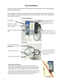
1
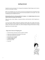
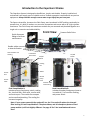
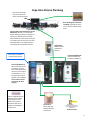
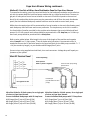
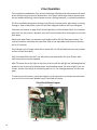
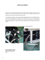
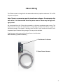
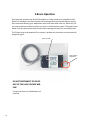
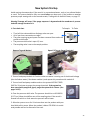
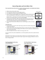
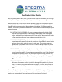
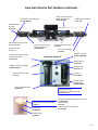
CAPE HORN XTREME INSTALLATION & OWNER’S MANUAL Katadyn Desalination, LLC Spectra Watermakers 20 Mariposa Road, San Rafael, CA 94901 Phone 415-526-2780 Fax 415-526-2787 www.spectrawatermakers.com Rev. May 2015 2 Table of Contents Getting Started .................................................................................................................... 4 Installation…………………………………………………………………………………………………………..…..5 Introduction ........................................................................................................................ 7 Installation Basics ................................................................................................................ 8 Cape Horn Extreme Plumbing ............................................................................................. 9 Product Water and Pressure Gauge Tube Installation ..................................................... 10 Parker Tube Fitting Assembly Procedure .......................................................................... 11 Spectra High Pressure Fitting Instructions ........................................................................ 12 Cape Horn Extreme Wiring ............................................................................................... 13 Optional Z-Ion and Z-Brane Installation and Instructions................................................. 15 Operation…………………………………………………………………………………………….………………...23 New System Startup Procedure ........................................................................................ 25 Dry Testing with an Artificial Ocean.................................................................................. 27 Normal Operation and Fresh Water Flush ........................................................................ 28 Service & Maintenance……………………………………………………………………………..…….29 Suggested Spares .............................................................................................................. 31 Maintenance ..................................................................................................................... 32 Introduction to Spectra Chemicals ................................................................................... 34 Storage Procedure ............................................................................................................ 36 Winterizing with Propylene Glycol ................................................................................... 37 Membrane Cleaning Procedure ........................................................................................ 38 Flow Test ........................................................................................................................... 39 Troubleshooting ............................................................................................................... 41 Technical Bulletins………………………………………………………………………………………………………..42 Parts Identification .......................................................................................................... 48 3 Getting Started Unpack the system and inspect it for damage during shipping. Freight damage must be reported to the carrier within 24 hours. Refer to the shipping list for your system to ensure you received all of the components listed. Do not discard any packaging until you have found and identified all of the parts. The small installation parts are listed on the kit list. Warning! We will not be held responsible for shortages and or freight damage that are not reported within thirty days of the ship date. Study the system layout diagram, component photos, and descriptions before beginning installation. Lay out the system. Before starting the installation identify where each module and component will be placed. Insure that there is enough clearance around the components for removal of filters and system service. Make sure you have adequate tubing and hose before starting. Additional parts may be ordered. Cape Horn Extreme Shipping List: 4 10% Clark Pump and reverse osmosis membrane module Feed pump module A with fresh water flush system Feed pump module B with pre-filter Accumulator tank assembly Analogue gauge assembly Installation fittings kit 5/8” Hose (2 x 25’) Service Kit Installation 5 6 Introduction to the Cape Horn Xtreme The Cape Horn Xtreme is designed to be efficient, simple, and durable. Properly installed and maintained it will supply years of reliable service. Prudent operation is required with any marine equipment. Always maintain enough reserve water to get safely into your next port. The Spectra Intensifier, known as the Clark Pump, was introduced in 1997 and has continually improved since. It is built of modern non-corrosive composites and comes with a 40” high rejection membrane. The Clark Pump and membrane module are pre-mounted and plumbed together as a single unit to save time and add reliability. Front View Quick disconnect fitting to facilitate maintenance. Pressure Relief Valve Double rubber mounts to absorb vibration Charcoal Filter and Housing Fresh Water Flush Valve On/Off Switch On/Off Switch Cooling Fan Service Port Service Valve Motor Shurflo pump head 5 Micron Filter and Housing Feed Pump Module A: Includes primary feed pump, switch, cooling fan, charcoal filter, flush valve, service valve, and service port. The module has compact and streamlined plumbing. The cooling fan increases longevity. Feed Pump Module B: Includes secondary feed pump (same as in module A), 5 micron filter housing, and power switch. Note: If your system came with the optional Z-Ion, the Z-Ion unit will replace the charcoal filter housing in Feed Pump Module A. The photo above, and all subsequent photos of feed pump module A, will look slightly different. See page 16 for Z-Ion installation and instructions. 7 Read the directions! Avoid tight hose bends and excessive runs. Use heavy gauge wire. Install feed pump modules as low as possible. Use a dedicated thru-hull with scoop type strainer. Do not mount components over electrical devices. Avoid getting dirt or debris into the piping or hoses during assembly. A small bit of debris can stop the system! Thru-hull Not Supplied. Seawater Flow Thru-hull Location: The system must be connected to a dedicated 1/2” to 3/4” forward facing scoop-type intake thru-hull and seacock. Install the thru-hull intake as far below the waterline and as close to centerline as possible to prevent air or contamination from entering the system. Do not install the intake close to, or downstream of a head discharge, keel, stabilizer fins, or other underwater fixtures. Thru-hulls near the bow are susceptible to air intake in rough conditions. Sharing a thru-hull can cause flow restrictions, intake of air bubbles or contaminants, and will void the warranty. For racing boats and high speed boats traveling above 15 knots, a retractable, snorkel-type thru-hull fitting is preferred because it picks up water away from the hull. The brine discharge thru-hull should be above the waterline, along or just above the boot stripe, to minimize water lift and back pressure. Double clamp all hose connections below the waterline. Avoid restrictions or long hose runs along the intake plumbing, from the thru-hull to the feed pump module. Secure the piping away from moving objects such as engine belts and hatches. Prevent chafe on the tubing as required. After several hours of operation, inspect all piping and hose clamps for leaks. Pipe Fitting Instructions: To seal plastic-to-plastic fittings, wrap 6 to 8 layers of Teflon tape around the threads. Hold the fitting in your left hand and tightly wrap the threads clockwise. For smoother assembly, do not tape the first (starting) threads. Wiring Pay attention to wire size or system performance will be impaired Perform wiring to UL, ABYC, CE or applicable standards 8 Cape Horn Xtreme Plumbing Note: Brine discharge may be connected to either side of Clark Pump Brine discharge thru hull (not included): place above waterline or tee into another visible drain. Spectra Clark Pump and Pressure Vessel/ Membrane: Mount in a cool location (below 120 deg. F/49 deg. C). May be oriented in any position and can be well above waterline. Leave access to the pressure relief valve. Do not mount over electrical equipment. Use supplied spacers and washers for the vibration mounts. Accumulator Tank: Dampens pulsations in feed line Fresh water from boat’s pressure water system Feed Pump Module B: Same instructions as Feed Pump Module A Feed Pump Module A: Mount vertically as low as practical, no more than 3 feet above waterline and not over electrical equipment, or anything that will be damaged by water. Leave at least 2-inches of clearance below for filter changes. Use the supplied 5/8-inch (15.9mm) clear braided vinyl hose for all runs. More hose may be ordered from Spectra, or bought at a hardware or marine store. Sea Strainer: Mount with supplied Quick Block and wire tie. Intake thru-hull 9 Product Water Plumbing and Pressure Gauge Tube Installation Product to tank: Route the product water from the valve into the top of a vented tank. Install a tee in the water fill or tap a pipe thread into an inspection port. Sampling Tap for testing the product water. DO NOT! feed the product into a vent line, manifold, or the bottom of the tank. Make sure that there is no restriction in this piping. Pressure in the product tubing must never exceed 5psi (.3bar), running or stopped, or the membrane will be permanently damaged. Product Sampling Valve: Mount using the supplied plastic straps as shown. Note: the handle points in the direction of flow. Pressure Gauge Use accumulator port to connect the pressure gauge with the supplied 1/4” black nylon tubing. Tubing must be pressure rated to 150 PSI (10 BAR). Product Flow Meter Use the supplied 1/4” black nylon tubing for the product plumbing. Product output fitting 10 Back view of instrument panel 11 Spectra High Pressure Fitting Instructions The Cape Horn Xtreme has eight high pressure fittings, two on each cylinder on the Clark Pump, two on the pressure vessel end caps, and two 90-degree elbows on the back of the Clark Pump. As the compression fitting is tightened, it compresses a ferrule onto the stainless tubing, fixing the ferrule permanently to the tube and holding the compression nut captive. The body of the fitting seals to the underlying component with an O-ring. On the Clark Pump cylinders and the end caps this O-ring is compressed by tightening the entire fitting. The Orings on the 90-degree fittings on the back of the Clark Pump have captive nuts and washers, which compress the O-rings without turning the entire fitting. If a tube fitting leaks it can sometimes be resealed by just tightening. You must use two wrenches, a 13/16-inch wrench to hold the base, and a 7/8-inch wrench to turn the compression nut. The 13/16-inch wrench will need to be thin so as not to interfere with the compression nut. If this doesn’t work, disassemble the fitting, grease liberally with silicone grease (the ferrule and the threads) and re-tighten firmly. The base O-rings should be gently compressed to achieve a good seal, and may be damaged by overtightening. Connector O-ring Ferrule Stainless Fitting Hex Nut Nickel-Bronze High Pressure Straight Fitting 12 Nickel-Bronze High Pressure Elbow Cape Horn Xtreme Wiring The Cape Horn Xtreme has two feed pumps, which may be operated independently. For maximum production, both pumps are run at the same time. To save power, or to reduce operating pressures, the system is run on a single pump. There are two main ways to wire the system: Method 1 is the standard installation, and preferable in most cases. Method 1: Two Pairs of Wires from Distribution Panel to Feed Pumps Route two pairs of wires, as in the diagram below, from two fuses or breakers on the main distribution panel. With switches or breakers on the distribution panel, this method allows you to control the pumps remotely, which is helpful if the system is difficult to reach. You may also control the system from the switches on the individual feed pumps during maintenance. Refer to wire guides below. Wire length is the sum of the length of the positive and negative wires. Example: In a 12-Volt system, 7 feet of duplex wire (two wires in a protective cover) is needed to connect the DC electrical panel to each feed pump module: 7 + 7 = 14 (the round-trip length), so you would use #12 Gauge (6mm²) wire for each feed pump. Connect wires using supplied terminal blocks, then seal connectors. Voltage drop will impair performance of the system. Feed Pumps (on/off switch on each pump) To Battery Wire size guide for 12-Volt system, with a pair of wires led to each feed pump module. Protect with 15 Amp Fuse or Circuit Breaker #10 Gauge (10mm²) up to 25 feet (7.5M) #8 Gauge (16mm²) up to 35 feet (10.6M) Wire size guide for 24-Volt system, with a pair of wires led to each feed pump module. Protect with 7.5 Amp Fuse or Circuit Breaker #14 Gauge(4mm²) up to 10 feet (3M) #12 Gauge (6mm²) up to 25 feet (7.6M) #10 Gauge (10mm²) up to 35 feet (10.6M) 13 Cape Horn Xtreme Wiring continued... Method 2: One Pair of Wires from Distribution Panel to Cape Horn Xtreme To streamline the wiring, one of the terminal blocks for the feed pump modules may be eliminated, with the power leads for both feed pump modules led to a single terminal block. Route a single pair of heavy wires from a fuse or breaker on the main DC electrical panel to the terminal block. By this method the whole system may be powered on and off from the main distribution panel, but the individual feed pump module switches must be used to control each pump. While the main supply wires will be protected by a fuse or breaker on the main distribution panel, each feed pump must still have overcurrent protection. The simplest way to do this is to add inline fuse holders (installer provided) to the positive wires between the terminal block and feed pumps. On 12-Volt systems each pump should be protected with a 7.5 Amp fuse; on 24-Volt systems each pump should be protected with a 4 Amp fuse. Refer to wire guides below. Wire length is the sum of the length of the positive and negative wires. Example: In a 12-Volt system, 7 feet of duplex wire (two wires in a protective cover) is needed to connect the DC electrical panel to the terminal block for the feed pump modules: 7 + 7 = 14 (the round-trip length), so you would use #10 Gauge (6mm²) wire. Connect wires using supplied terminal block, then seal connectors. Voltage drop will impair performance of the system. Main DC Electrical Panel Feed Pump Wiring: Red is positive Black or yellow is negative DC negative bus bar Fuses for each pump along positive wire: Feed Pumps (on/off switch on each pump) To Battery Wire Size Guide for 12-Volt system, for a single pair of wires to Cape Horn Xtreme. Protect individual feed pumps with 15 Amp fuses. #10 Gauge (6mm²) up to 15 feet (4.5M) #8 Gauge (10mm²) up to 25 feet (7.5M) #6 Gauge (16mm²) up to 35 feet (10.6M) 14 Wire Size Guide for 24-Volt system, for a single pair of wires to Cape Horn Xtreme. Protect individual feed pumps with 7.5 Amp fuses. #12 Gauge(4mm²) up to 10 feet (3M) #10 Gauge (6mm²) up to 25 feet (7.6M) #8 Gauge (10mm²) up to 35 feet (10.6M) Optional Z-Ion and Z-Brane Membrane Protection Systems The Z-Ion and Z-Brane, both developed by Spectra, are systems to protect the reverse osmosis membrane from fouling for extended periods without fresh water flushing or storage chemicals (pickling). The Z-Ion achieves this end by introducing a stream of metallic ions into the fresh water flush module, thus flooding the entire system with ions that prevent biological growth for up to thirty days. If you are going to let your system sit idle for longer than thirty days, treatment with SC-1 storage chemical or propylene glycol is still required. The Z-Brane applies zeta potential high voltage capacitive current to the membrane pressure vessel, creating an unfriendly environment for bio-film and bacteria, and assists in the prevention of scale formation on the membrane surfaces. After thoroughly fresh water flushing the system, the Z-Brane will protect an idle system indefinitely as long as the Z-Brane is energized. The Z-Brane draws less than 1 Amp, but storage with chemicals may be preferable for longer periods if battery power is an issue. Neither the Z-Ion nor the Z-Brane will prevent freezing, so in freezing climates pickling with propylene glycol is still required. Even with the Z-Ion or Z-Brane there may still be cases where you need to pickle your system with SC-1 storage chemical or propylene glycol, so we recommend you carry one of these products at all times. If your system was ordered with either of these systems, they will require only some basic wiring and commissioning, laid out in the following pages. If you didn't order you system with the Z-Ion or Z-Brane, either can be retrofitted to any Spectra system. 15 Z-Ion Installation If you did not order your Cape Horn Xtreme system with the optional Z-Ion you may disregard this section of the manual. If you ordered your Cape Horn Xtreme with a Z-Ion, the feed pump module will come with the Z-Ion installed in place of the standard fresh water flush module, as shown, with a separate ZIon electronic control box: Feed Pump Module A: Fresh water flush valve: manually opened at the start of the cycle and closed at the end. Flow regulator Flow sensor or “trigger:” Starts Z-Ion cycle when it senses water flow. Generator bowl with charcoal filter. System electrical bus bar: Z-Ion will connect here (or any convenient connection to ship’s power). Control Box: Z-Ion control box: Mount in a visible location near the feed pump module. Connector for flow sensor Connector for generator bowl Control Box Connections The control box comes with four-foot cables for flexibility in mounting on the bulkhead adjacent to the feed pump module. Plug the connector from the generator bowl and the flow sensor into their corresponding connectors from the control box. It is impossible to reverse them, but it is possible to connect the generator bowl to the flow sensor, which is incorrect. 16 Z-Ion power cable with in-line fuse: Connect to the system electrical bus or other source of ship’s power. Z-Ion Installation continued... Connections from generator bowl and flow sensor connected to control box. Z-Ion Power Connections Turn the main DC breaker off or remove the main power fuse to the watermaker. Locate the DC Bus Bar for the watermaker (or any other DC power source), as shown below. Connect the DC power leads from the Z-Ion Control Box to the Incoming DC Bus Bar. Pay attention to polarity! Connect Red (fuse) to DC + Yellow (or black) to DC Replace protective cover Z-Ion Fuse holder: Install in a dry location with easy access. 17 Z-Ion Operation This revolutionary adaptation of an ancient technology effectively and safely protects the membrane and filters on your Spectra Watermaker. Your system will be kept ready to operate without any additional flushing, external power sources, pickling chemicals, or complex procedures. The Z-Ion should be energized at all times, but will only consume power when water is running through it. Upon initial power-up the LED will flash red/green and then will turn solid green. Follow the instructions on page 28 for Normal Operation and Fresh Water Flush. For treatment with the Z-Ion, the process is identical, only the Z-Ion will release silver and copper ions into the flush water. When fresh water flows, the operation cycle begins and the LED will flash green/amber. The cycle will continue until either the water flow stops or the adjustable timer times out (factory set for 15 minutes). If the voltage is out of range, below 10V or above 56V, the LED will flash red every two seconds and the unit will shut down. Each fresh water flush with the Z-Ion will protect your watermaker for up to 30 days, after which the process must be repeated. After 720 cycles the service light on the front of the control box will light up, indicating that the probes on your Z-Ion may be wearing down, and should be tested. The service light is just a reminder, and the Z-Ion will go on functioning while it is lit. For testing procedures, see the next page. To reset the service counter, touch two magnets, at the same time, to the two red reed switches on the Z-Ion circuit board, labeled Switch 1 and Switch 2 below. Z-Ion Circuit Board Layout Pin 1 Switch 1 18 Pin 7 Switch 2 Testing the Z-Ion Normally no adjustment is necessary as the unit has been set up at the factory for your watermaker, however it is advisable to make sure the Z-Ion is working properly. Likewise, the following test is the only way to know if the probes on the Z-Ion need replacement. There is no way to test for silver ions, but we can test for copper ions. The Z-Ion puts both into the flush water, and where there is one there is the other. You will need Spectra test kit (ELZION-TESTKIT) or a similar copper test kit for pools and spas. Once the installation is complete and the unit is powered up, carry out a fresh water flush per the instructions on page 28. The LED on the Z-ION controller should flash as the unit cycles. Close to the end of the flush cycle, take a sample of the brine discharge. If the brine discharge thru-hull isn't accessible you will need take a sample from the brine outlet on the Clark Pump, or use the brine discharge service hose. Once you have obtained a sample, first check it with a salinity meter to make sure the salinity is below 1000 PPM. Next, use the copper test kit to make sure the flush water contains between .5 and 1 Parts Per Million of copper. Note: A new carbon filter will sometimes absorb some of the copper ions, causing a copper test to read low. Samples should be taken after a new carbon filter has been wet for a few days. If the flush water does not have adequate copper content then please contact our technical support for instructions on how to adjust the system. Copper test kit: 19 Z-Brane Installation Spectra ships the High Pressure Module with the white Z-Brane anode(s) removed from their socket(s) to prevent shipping damage. Before the High Pressure Module (Clark Pump and Membrane) is mounted the anodes should be installed. The membrane housing has been capped with shipping plugs to keep the membranes clean and moist during shipping and storage. Remove the C-clips that secure the shipping plugs, then remove the plugs. Insert an anode into the membrane until the groove is flush with the membrane end plug. The C-clip will then slip into the groove, and the C-clip screw will secure the clip. C-Clip and retaining screw Shipping Plug NOTE: your watermaker will only have one membrane. In these pictures there are three membranes. 20 C CLip C-Clip groove in Anode Z-Brane Wiring The Z-Brane system is integral with the watermaker and only requires continuous 12V or 24V DC power to operate. Note: There is no reason to open the transformer enclosure. Do not service this unit unless it is disconnected from the power source! There may be high voltage present. We recommend that the Z-Brane be connected to a discreet continuous power source. The power must be on when the watermaker is in operation and when the Z-Brane is used for membrane storage. If the power is obtained from the MPC circuit board then the MPC must be powered up at all times during storage. This may not be desirable. Fuse the power at the source with a 1 amp fuse or circuit breaker. Red is Positive (+) , Black is Ground (-) Transformer Enclosure Z-Brane Power Harness 21 Z-Brane Operation During normal operation the Red LED should be on. Power needs to be supplied to the ZBrane unit whenever you wish to prevent bio-fouling and have protection against scaling. We recommend flushing your watermaker with fresh water after each use, which will protect your membrane and also prevent corrosion in the feed water system. Thoroughly Fresh Water Flush the watermaker several times before leaving the vessel for extended periods. The Z-Brane may be de-powered if the system is pickled with chemicals or winterized with propylene glycol. Power on LED High Voltage connector DO NOT DISCONNECT OR SPLICE ANY OF THE HIGH VOLTAGE WIRING! Contact the factory if modifications are required. 22 Operation 23 24 New System Startup Avoid running the watermaker if the vessel is in contaminated water, such as in a polluted harbor or canal. The system should be fully run tested before you leave port. If the location or weather prevents proper testing refer to the manual section, Testing with an Artificial Ocean, on page 27. Warning! Damage will occur if the purge sequence is bypassed and the membrane is pressurized with storage chemical in it. 1. First check that: To Sample To Tanks Thru-hull inlet valve and brine discharge valve are open. All of your hose connections are tight. The green warning tag and spacer has been removed from under the pressure relief valve The pressure relief valve is open 1/2 turn. The sampling valve is set to the sample position. Remove Tag and Washer! Open 1/2 Turn to Purge Chemicals! 2. Turn on feed pump module A. Check to make sure water is coming out of the brine discharge (thru-hull above water). Shut down module A, and repeat this procedure with module B. 3. Turn on both feed pump modules and run the system WITHOUT PRESSURE for 20 minutes to purge the storage chemicals. If the system has been stored with propylene glycol, purge the system for 4-6 hours. (See pages 34-35). 4. Close the pressure relief valve. The pressure should rise to 90-100 PSI (6.2-7 bar). Water should flow out of the sampling tube. If the vessel is located in brackish or fresh water the pressure will be lower. 5. Allow the system to run for 10 minutes then test the product with your hand held salinity tester. When the product is below 750 PPM it is considered potable and can be diverted to the tank. 25 26 MAX 20 10 12V ≈ 19 ≈9 Both Pumps Single Pump ≈ 4.5 ≈ 10 24V AMPS 5 11 MAX 60-80 30-35 4.2-5.6 20-25 6.3-7 PSI PSI 90-100 Pres- Pressure bar Static * Feed 1.7 2.8 GPM Flow 6.4 10.6 LPM Feed Flow MIN 1.6 2.7 6.0 10.2 GPM LPM MIN Nominal Parameters 8.7 15 GPH Flow 32.9 56.7 LPH Flow MIN 8 14.5 GPH Product Flow 30.2 54.8 LPH MIN 13 16 Nom 16.5 18.4 Max Watts/Gallon Over the course of regular use you will balance the service life of the pumps, production quantity, and energy consumption when deciding when to run the system, and whether to run one or both pumps. When running just one pump, it doesn’t matter whether you run feed pump A or B. In cold temperatures it may be necessary to run just one pump to reduce system pressure, as colder water will increase operating pressure. Be sure to never operate the system with feed pressures above 125 PSI (8.6 Bar). 6. The system may be run with only one feed pump at a time or with both pumps simultaneously. Water quality may improve slightly when running with both pumps, as product salinity decreases with higher feed pressure. New System Startup…continued Testing with an Artificial Ocean If it is not possible to test run the system with the boat in the water, testing may be accomplished with an artificial ocean. You will need 1.3 lbs. of non-iodized salt (rock salt, sea salt, or aquarium salt) to make 5 gallons (605 grams of salt per 20 liters) of seawater that is about 33,000 PPM salinity (average Seawater salinity). A good rule of thumb is 1/2 cup (.12 liters) of salt per gallon (4 liters) of water. Make sure the domestic water system is powered up and the boat’s tank has at least 30 gallons (120 Liters) of water to purge the storage chemicals from the system. Confirm that the charcoal filter is installed, and the domestic water line is connected. 1. 2. 3. 4. Open the pressure relief valve on the Clark Pump half a turn. Remove the green tag and spacer! Turn the yellow service valve on feed pump module A to OFF. Open the grey flush valve on the charcoal filter housing on feed pump module A. Start a feed pump (Flip metal toggle switch to ON, located on the top right corner of feed pump module A). Let feed pump run for 20 minutes to purge the storage chemicals. 5. Stop the feed pump (metal toggle switch to OFF). 6. Connect the inlet service hose to the service port on feed pump module A, then connect the brine discharge service hose to the quick disconnect on Clark Pump. Refer to the photos below. Route both hoses into a 5 gallon (20 Liter) bucket. Turn product sample valve to the sample position and route the product water into the bucket. 7. Open the grey flush valve and turn on the feed pump until the container is filled with fresh water. Stop the pump and close the grey flush valve. 8. Turn the yellow valve on feed pump module A to SERVICE. 9. Mix the salt to the proper proportion or use an aquarium hydrometer to adjust the specific gravity to 1.025. 10. Start the feed pump, allow to prime, then close the pressure relief valve on the Clark Pump. The system should build pressure and start making water. 12. Run the system under pressure and check for proper operation and leaks. After testing the system stop the feed pump. Remove the inlet service hose and replace the brine discharge hose. Turn yellow service valve to RUN. Perform a fresh water flush (next page). A fresh water flush will hold the system for 5 days. If you don’t use the system in 5 days we recommend the storage procedures on pages 36 or 37. Valves in flush position: Flush Valve OPEN Open the pressure relief valve on Clark Pump 1/2 turn: Service Intake Port Service Valve OFF Valves in service position: Connect the brine discharge hose: Flush Valve CLOSED Service Hose ATTACHED Service Valve to SERVICE 27 Normal Operation and Fresh Water Flush If the system has been pickled, stored, or contains cleaning compounds, use the New System Startup procedure on page 25. 1. 2. 3. 4. Make sure the inlet thru-hull is open. Turn the product sample valve to the SAMPLE position. Turn yellow service valve on feed pump module A to RUN. Start the feed pump (metal toggle switch on feed pump module to ON) and check for flow by inspecting the brine discharge or checking for pressure on your analogue gauge. If there is no flow open the pressure relief valve on the Clark Pump and bleed the air out of the feed pumps by running them one at a time. 5. Close the pressure relief valve. After 5 minutes check the product water with your hand held salinity tester. When it is below 750 PPM, divert the product into your tank by rotating the product sample valve handle 90 degrees. 6. Run the system until you have filled your tank or made enough to meet your requirements. Product Sample Valve Analogue Gauge Panel Fresh Water Flush 1. Turn the yellow service valve to OFF. Open the grey flush valve on filter housing at top of feed pump module A. 2. Flush for three minutes, alternating between pumps to circulate fresh water through the entire system. Pressure will drop on the gauge, which indicates that the membrane is flooded with fresh water. Stop the feed pumps. 3. Return the yellow service valve to RUN. Close the grey flush valve. You may now leave the system unattended for up to five days (30 days with the Z-Ion) without further attention Remember that you need to run the system almost a half an hour to make enough water for a fresh water flush. You may notice that the system output is higher while charging your batteries as the machine is voltage sensitive. Feed Pump Module A with valves in the RUN Position: Feed Pump Module A with valves in the FLUSH Position: Closed RUN 28 Open OFF Maintenance, Storage, and Troubleshooting 29 30 Suggested Spares Short term cruising, weekends, etc.: We suggest a basic Cruise Kit A. This kit consists of six 5 micron filters and SC-1 storage chemical. Cruising 2 to 6 months at a time: Two basic cruise kits, one replacement charcoal filter, one replacement feed pump head. Longer than 6 months: Additional filters, Offshore Cruising Kit consisting of Clark Pump seals, O-rings, tools, and membrane cleaning chemicals. One replacement strainer screen, O-ring for strainer screen, O-rings for filter housings. Additional feed pump head and/or feed pump diaphragm. Common Parts SC-1 STORAGE CHEMICAL SC-2 CLEANER SC-3 CLEANER BASIC CRUISE A OFFSHORE REBUILD KIT 5 MICRON FILTER CHARCOAL FILTER 5” STRAINER SCREEN OIL/WATER FILTER FEED PUMP FEED PUMP HEAD FEED PUMP DIAPHRAGM 5” STRAINER O-RING FILTER HOUSING O-RING CHARCOAL FILTER HOUSING O-RING Part Number KIT-CHEM-SC1 KIT-CHEM-SC2 KIT-CHEM-SC3 KIT-BCK-A KIT-OFFSH FT-FTC-5 FT-FTC-CC FT-STN-5S FT-FTC-OW EL-FP-12V or 24V PL-PMP-SFPH EL-FP-DP SO-STN-5SS SO-FHS-10H SO-FHS-3PCS10 31 Maintenance General Periodically inspect the entire system for leakage and chafing. Repair any leaks as soon as you find them. Some crystal formation around the Clark Pump blocks is normal. Wipe down any salt encrusted areas with a damp cloth. Watermakers are at their best when run regularly. Biological fouling in the membrane is more likely when a watermaker sits idle. A warm environment will cause more growth than a cold environment. A fresh water flush every five days will greatly reduce biological growth but may not stop it completely. You can also protect your watermaker with the optional Z-Brane or Z-Ion systems: Both protect the membrane from bio-fouling without the use of storage chemicals. The Seawater Strainer The seawater strainer’s stainless steel element should be inspected, removed, and cleaned as needed. Ensure that the thru-hull is closed before disassembly and the gasket is in place before reassembly. When the system is put into storage, remove the strainer, rinse with fresh water, and reassemble dry to impede corrosion. Check frequently during operation. The Pre-filter Service the pre-filter on a regular basis. If the system is installed as shown on pages 9 and 10, the pressure will fall on the remote gauge as the pre-filter becomes dirty. Extremely dirty filters will harm system performance and may cause the feed pump to cut out from high pressure. Leaving dirty filters in the machine during long idle periods will cause biological contamination. To service the pre-filter, turn yellow service valve on feed pump module A to OFF, open the housing, and remove the old filter. Clean out the housing bowl, reassemble the housing with a new 5 micron filter element. Leave dry until next startup. Use only Spectra approved filters or you may void your warranty. The filters may be cleaned up to three times with a soft brush and water in a bucket, hung overboard overnight, or dragged behind your vessel underway. Drying in the sun helps remove odors. Occasionally, lightly lube the filter housing O-ring with silicone grease. Oil Water Separator (Optional) For oil/water separation, install the additional filter housing with its oil removal filter upstream of the 5 micron filter. Service at the same time as the 5 micron filter. The Charcoal Fresh Water Flush Filter Replace the charcoal filter element at least every 6 months. This filter protects the membrane by removing chlorine from the flush water. Use only a Spectra-approved replacement. See page 44. 32 The Feed Pumps and Clark Pump The feed pumps and the Clark Pump require no routine maintenance except inspection for leaks. Tighten any hose clamps or fittings that show signs of leakage. The high pressure fittings threaded into the Clark Pump have O-ring seals with a straight thread. These should never leak and should never be over-tightened. If one of the tube nuts starts to leak, it can be unthreaded, sealed with a bit of silicone grease or oil, and tightened with two wrenches very tightly (see page 12). The Membrane Always perform a flow test (page 39) before cleaning your membrane. Cleaning with chemicals shortens the lifespan of membranes, so only clean if you are certain it is warranted. The leading cause of fouling is biological growth that forms when the system is left unused without flushing or pickling. Fouling from mineral scaling can happen during operation under certain seawater conditions, and from rust. Monitor the product salinity and feed pressure for higher than normal readings, and take environmental conditions into consideration: Cold feed water or clogged filters can cause high pressure. Low product flow is usually due to low voltage, a worn feed pump, or a worn Clark Pump. Test to see if biological growth has occurred: Before running the system, remove the prefilter and examine its condition. If the filter housing is full of smelly, discolored water, the system was not properly stored. Install a clean pre-filter. Next, check the membrane. Attach the brine discharge service hose and lead it into a bucket. Open the pressure relief valve half a turn, and manually run the system for 30 seconds (metal toggle switch on feed pump module). Examine the brine water: If it is discolored and smells bad, perform an SC-2 cleaning with unchlorinated water before running the system pressurized. If the brine is fairly clean, follow the New System Startup procedure on pages 25-26 and run normally. Check for performance. Clean the membranes only if performance is reduced. See the Cleaning Procedure on page 38 for complete instructions. 33 Introduction to Spectra Chemicals We use four types of chemicals: SC-1, SC-2, SC-3, and propylene glycol antifreeze. SC-1 and propylene glycol are for system storage, while SC-2 and SC-3 are for membrane cleaning. Do not use metasodium-bisulfate, citric acid, or any other storage chemical not supplied by Spectra. These chemicals, used to store other watermaker brands, are very acidic and will damage the Clark Pump and void the warranty. Note: Never use any chemicals with the system pressurized! Always open the pressure relief valve 1/2 turn. Always follow the instructions for purging the chemicals as shown in the New System Startup section on pages 25-26. Storage SC-1 prevents biological growth when your system is idle. It should not be used as a cleaning chemical, nor will it protect your system from freezing. A jar of SC-1 is mixed with 1 to 3 gallons of product or dechlorinated fresh water in a bucket and circulated through the system for 10 minutes. This treatment will protect the system for six months, after which the SC-1 treatment must be repeated. To use SC-1, follow the instructions for Storage Procedure on page 36. Spectra systems should be stored with propylene glycol if freezing is likely to occur. Propylene glycol can be used instead of Spectra SC-1 storage chemical for storage in any climate, and treatment is effective for one year. Propylene glycol is a food-grade antifreeze used to winterize RV’s, boats, and cabins. Do not use ethylene glycol automotive antifreeze, which is toxic and will damage the system. The propylene glycol formulations sold in marine and RV stores are usually diluted with water. The water remaining in the watermaker before the storage procedure will further dilute the antifreeze, reducing the microbial protection and increasing the temperature at which the mixture will freeze. Antifreeze labeled “Minus Fifty” is a 25% solution and will begin to form an icy slush at about +15Degrees F (-10C) and will only provide burst protection to about Zero F (-18C). After a further 50 percent dilution by water remaining in the watermaker, “Minus Fifty” antifreeze will only protect from bursting down to about +25F (-4C). Therefore if low temperature freezing protection is required a 60% or stronger antifreeze should be used. 60% solutions are labeled “Minus 100” and will provide burst protection to -15F (-27C) even after a 50 percent dilution with residual water. “Minus 200” formulations are pure propylene glycol. 34 Introduction to Spectra Chemicals continued... Complete microbial preservative protection requires a 25% solution of propylene glycol, so care must be taken that the solution remaining in the watermaker during long term storage is at least 25%, even if freeze protection is not required. For these reasons Spectra recommends that all pickling be carried out with a 60% or greater concentration. See Winterizing with Propylene Glycol on page 37. Propylene glycol can be difficult to flush from a membrane, especially after extended storage periods. This results in high salinity water (high PPM) and residual flavor in the product water. We recommend flushing the system WITH THE PRESSURE RELIEF VALVE OPEN for 4-6 hours after storage with propylene glycol—the longer the better. If, after extended flushing, you still experience low product water quality, cleaning with SC-2 usually removes all traces of propylene glycol and returns the salinity to the level it was before storage with propylene glycol. See the Cleaning Procedure on page 38. Cleaners Cleaning can be detrimental to the membrane and shorten its life. Avoid unnecessary cleaning, and avoid cleaning as a diagnostic tool. SC-2 is an alkaline cleaner used to remove light oil, grime and biological growth. It is most effective if heated to 120 deg. F (49 deg. C), which is difficult on a boat. In most cases the water quality will increase in PPM (salinity) after an SC-2 cleaning. After a few hours it should recover to near the level it produced before the cleaning. SC-3 is an acid cleaner used to remove mineral and scale deposits. In most cases this is used first and if there is no improvement, go on to the SC-2. SC-3 will in most cases lower the product PPM and overall pressures. Scaling is a slow process that may take several months or years. SC-3 is less harmful to the membrane and will almost always improve the performance of an older membrane. For cleaning with either SC-2 or SC-3, see the Membrane Cleaning Procedure on page 38. 35 Storage Procedure NOTE: When storing with SC-1 you only need to use one feed pump to circulate the storage solution through the watermaker, but you should briefly alternate pumps to ensure that the SC-1 solution is circulated throughout the system. The watermaker will contain about 2 gallons (8 liters) of water, so starting with one gallon in the bucket there will be about 3 gallons (12 liters) of solution. Make sure the pressure relief valve on the Clark pump is Open (unpressurized), 1/2 turn counterclockwise OR THE MEMBRANE WILL BE DAMAGED. 1. Perform a fresh water flush (page 28). Turn off the feed pump and close the grey fresh water flush valve. Leave the yellow service valve OFF. 2. Disconnect the brine discharge hose from the Clark Pump, and replace with the brine service hose from your service kit. Lead the brine service hose into a bucket. 3. Do another fresh water flush and run the feed pump until you have one gallon (4 liters) of fresh water in the bucket. Turn off the feed pump and close the grey fresh water flush valve. 4. Mix one container of SC-1 storage compound with the water in the bucket. It will not dissolve completely, which is normal, and any particles will be caught by the filter. 5. Connect the intake service hose to the service port on feed pump module A and lead the hose into the solution in the bucket. Turn the yellow service valve to SERVICE. The system will now draw the solution from the bucket and return it via the brine discharge service hose. 6. Turn on a feed pump and circulate the storage chemical through the system for approximately 10 minutes, alternating feed pumps. Turn off the feed pumps. Clean Up: Remove the brine discharge service hose, and replace the brine discharge hose leading to the thru-hull. Turn the yellow service valve back to RUN, and remove the intake service hose. Close the seacock, drain and clean the sea strainer and pre-filter. Reassemble dry with a new filter. Your system is now protected for the next six months. Feed Pump Module Valves in flush position: Flush Valve OPEN Opening the pressure relief valve On Clark Pump 1/2 turn: Service Valve OFF Valves in service position: Connecting brine discharge hose: Flush Valve CLOSED Service Hose ATTACHED Service Valve to SERVICE 36 Winterizing with Propylene Glycol 1. Fresh water flush the watermaker (page 28). Turn off the feed pumps. Close the grey flush valve (located on feed pump module A). 2. Connect the inlet service hose to the service intake on feed pump module A, and lead it into a bucket. Turn the yellow service valve to the SERVICE position. 3. Connect the brine discharge service hose to the quick disconnect on the side of the Clark Pump and lead it into a second container. 4. Pour 1 gallon (4L) of propylene glycol of appropriate concentration (see pages 34-35) into the bucket with the intake service hose. 5. Make sure that the pressure relief valve on the Clark Pump is OPEN a 1/2 turn, OR THE MEMBRANE WILL BE DAMAGED. 6. Turn on one of the feed pumps until about a gallon of water has flowed from the brine discharge, or propylene glycol appears. Propylene glycol will look slightly different, and feel more slippery, than water. Stop the pump. Add more antifreeze to the intake bucket if necessary. 7. Lead the brine discharge service hose into the bucket of propylene glycol. The system will now draw propylene glycol from the bucket and return it via the brine discharge hose. 8. Circulate the antifreeze in this manner for about 10 minutes, alternating feed pumps. 9. Stop the feed pumps. Reconnect the brine discharge hose that leads to thru-hull. Run the feed pump until the bucket is empty. 10. Close the seawater intake. Turn yellow service valve to OFF. Drain the seawater strainer and the hose leading to the feed pump modules. Disconnect the product tubing from the membrane housing and blow residual water out of the tubing. Empty the charcoal filter housing and flush water lines. Your watermaker is now protected from biological growth and freezing for one year. Opening the pressure relief valve on Clark Pump 1/2 turn: Feed Pump Module Valves in flush position: Flush Valve OPEN Service Valve OFF Connecting brine discharge hose: Valves in service position: Flush Valve CLOSED Service Intake Hose ATTACHED Service Valve to SERVICE 37 Membrane Cleaning Procedures Note: Procedures are the same for the SC-2 and SC-3 cleaners A Spectra cleaning compound (SC-2 or SC-3) must be mixed with fresh water at a ratio of 1 container of compound to 3 gallons (12L) of unchlorinated fresh water. An average of two gallons (8 liters) of water is already present inside a Cape Horn Xtreme system, and this water must figured into the mixture. Warm water is ideal for cleaning membranes: Use a large stainless steel pot to heat the solution to 120° (49°C). You might have to periodically stop and reheat the solution. 1. Perform a fresh water flush (page 28). Stop the feed pumps and close the grey flush valve. 2. Connect the inlet service hose to the service intake on the feed pump module A. Connect the brine discharge service hose to the quick disconnect on the Clark Pump. Lead the hoses into a bucket. Open the grey flush valve and run feed pump A until you have one gallon (4 liters) of water in the bucket. 3. Turn off the feed pump and close the grey fresh water flush valve. 4. Turn the yellow service valve on feed pump module A to SERVICE. 5. Make sure the pressure relief valve on the Clark Pump is OPEN 1/2 a turn (system is un-pressurized) OR THE MEMBRANE WILL BE DAMAGED. 6. Mix the cleaning chemical with the water in the bucket. 7. Start feed pump A and circulate the chemical through the system for 45 minutes, if the solution is warm. Let the solution sit in the unit overnight if the cleaning solution is cold. 8. Stop the pump, replace the brine discharge hose, and run the pump until the bucket is empty. Stop the feed pump and turn the yellow service valve to RUN. Follow the instructions for a New System Startup (pages 25-26). KEEP PRESSURE RELIEF VALVE OPEN to flush out the cleaning chemicals. Feed Pump Module Valves in flush position: Flush Valve OPEN Opening the pressure relief valve Service Valve OFF Valves in service position: Connecting brine discharge hose: Flush Valve CLOSED Service Hose ATTACHED Service Valve to SERVICE 38 Flow Test for Dual ShurFlo Pumps (Cape Horn Xtreme) The flow test is the most useful diagnostic test for system performance, and should be done before replacing or cleaning your membrane. Changes in production or water quality are normally caused by something other than the membrane, unless the system has been left unused for a long time. Before the flow test, change the pre-filter and clean the sea strainer. Carefully check for water or air leaks, as air in the system will cause low production and erratic salinity. Look for air bubbles in the product flow meter, feed water hoses, and brine overboard hose. Run the system and watch the pressures very closely. If the feed pressure to the Clark Pump is asymmetrical from one stroke to another, this could be part of the problem. A difference of a few PSI is acceptable, but anything over that is an issue. If the pump is asymmetrical, Clark Pump repairs should be done before continuing with these tests. If no asymmetry is noted, continue with this test. You will need a graduated bucket, either a graduated pitcher or large measuring cup, and a stopwatch. Before the flow test, change all filters and clean the sea strainer. Carefully check for water or air leaks, as air in the system will cause low production and erratic salinity. Observe the feed pressure and ensure that the Clark Pump cycles symmetrically. Log the voltage at the feed pumps at the same time. Confirm at least 12.5 Volts at the feed pump on 12-Volt DC systems; 25 volts on 24-Volt DC systems. Take two measurements and compare them with the table on page 28 of this manual. The first measurement is the product flow alone. The second is the product flow combined with the brine discharge flow to get the total flow or feed flow. You may take these measurements by two methods: 1. Time the product flow into a graduated pitcher, then divert both the product flow and brine discharge together into a bucket to measure total flow. OR 2. Divert the product flow into the pitcher while diverting the brine discharge into the bucket. Time the flow of both. After calculating the product flow, pour the pitcher of product into the bucket of brine to measure total flow. The ratio of product flow to total flow gives us the recovery rate, expressed as a percentage. If the percentage is below the minimum it indicates an internal leak in the Clark Pump. 39 Flow Test continued... On the Cape Horn Xtreme, you should perform the tests using each pump alone, then using both pumps. Compare the results to the table on page 26. 1. Product Flow: Product flow is expressed in Gallons Per Hour (GPH) or Liters Per Hour (LPH), by this equation: 3600 ÷ time in seconds x quantity of water in gallons or liters=GPH or LPH There are 3600 seconds in an hour. Example: It took 3 minutes and 35 seconds to collect 1 gallon of product water. 3600 ÷ 215 x 1 = 16.74 GPH (3 minutes, 35 seconds is 215 seconds) Example: It took 2 minutes and 25 seconds to collect 2.5 liters of product water. 3600 ÷ 145 x 2.5 = 62.07 LPH (2 minutes, 25 seconds is 145 seconds) 2. Total Flow or Feed Flow: Feed flow or total flow (brine + product) is expressed in Gallons Per Minute (GPM) or Liters Per Minute (LPM) , by this equation: 60 ÷ time in seconds x quantity of water in gallons or liters = GPM or LPM Example: It took 1 minute and thirty-seven seconds to collect 5 gallons of total flow. 60 ÷ 97 x 5 = 3.09 GPM (1 minute, 37 seconds is 97 seconds) Example: It took 53 seconds to collect 12 liters of total flow. 60 ÷ 53 x 12 = 13.58 LPM 3. Recovery Rate: Product Flow ÷ Total Flow = Recovery Rate % Example: 6.5 GPH product flow = .063 or 6.3% 1.7 GPM total flow x 60 (you must first multiply total flow by 60 to convert from GPM to GPH) In order to make good water, you need the proper amount of feed water flow. Each pump alone should produce 1.5 gallons per minute (5.7 LPM) of brine discharge PLUS product water. Running on both pumps the flow should be 2.7 GPM (10 LPM). Compare the product flow to the total feed flow. Product flow should be 9.5% of total flow for a Cape Horn Xtreme. If product percentage is low, you may have an internal leak in the Clark Pump. For every 1/10th of a GPM feed water flow loss, we will lose about 1/2 gallon per hour of product flow and the salinity will go up 100 PPM. Low feed flow combined with low system pressures is most frequently due to worn Shurflo pump heads (PL-PMP-SFPH). 40 Troubleshooting Cape Horn Extreme Systems Symptom Cause Pump runs intermittently, cycling on/off Overpressure switch on Shurflo pump opening Feed pump runs with loud noise Intake blocked Air in system Remedy Adjust or replace switch (see pages 45-46) Check thru-hull valve Check sea strainer for leaks Check fresh water flush module for leaks Re-prime system (restart) Feed pump air locked Open pressure relief valve to bleed the air then close to start. Pressure relief valve open Close valve. Pre-filter excessively clogged. Change filter. Closed valve or blockage in flow. Check flow path for closed valve or kink in hose. Low Water Production High Amperage. High Feed Pressure Strainer or pre-filter clogged. Service pre-filter and strainer. Low Water Production, Pressure Relief valve partially open. Close Valve Perform flow test (pages 39-40) Low Feed Pressure. Worn Pump head Replace Pump Head. Water Production normal but High Feed Pressure, High Amperage. Cold seawater temperature Normal condition Fouled membrane Clean membrane Water Production normal but Lower Pressure, Lower amperage Warm sea water or brackish water. Normal Condition. Asymmetrical pressure and flow readings between pump shifts Check valve leaking Contact dealer or see the Clark Pump repair manual. Feed pumps run but no pressure. Feed Pumps start but shut down on high pressure. Failed annular ring. Shaft Seal leaking. 41 Technical Bulletins The following pages include Spectra’s most commonly used technical bulletins, addressing tests, adjustments, troubleshooting, and common points of confusion. DWYER FLOW METER SERVICE The mechanical flow meter, PL-FMT-10 (10 GPH range) or PL-FMT-20 (20 GPH range) can be opened for cleaning if it becomes difficult to read or if the little ball gets stuck. The flow meter will come completely apart for cleaning. First remove the meter from the panel. Remove the four small screws that hold the stainless steel bracket in place. Carefully pry off the bracket. On the very top of the meter is a clear plastic slide-off cover over an Allen screw. Use a flat bladed screwdriver to push the cover off. Holding the meter upright, remove the Allen screw with a ¼” Allen wrench. Invert the flow meter and catch the ball as it falls out. You can use tooth paste or plastic window polish to polish the inside using a small bottle brush. Clean the ball and give it a few coats of wax. If the O-rings are damaged or the unit has been leaking, install new O-rings using a little silicone grease to ease assembly. These are standard O-rings and should be available at most larger auto parts or bearing stores. Reassemble in reverse. ACCUMULATOR PRESSURE Your Spectra watermaker is supplied with a pressure accumulator tank (PL-ACC-TK), which should be installed in the feed water line between the pre-filters and the Clark Pump. The purpose of the feed line accumulator is to reduce the spikes in the feed pressure caused by the cycling of the Clark Pump. If the accumulator is not properly charged it can lead to problems with the Shurflo pump pressure cutout switches (see page 46). The accumulator has a Schrader air valve, like a car tire, which allows the internal air bladder of the accumulator to be pre-charged. The accumulator should be pumped up to about 65 psi (4.5 bar) for best results. Add air using a tire pump or air compressor. You can experiment with the exact pressure that will give the best pulsation dampening on your installation. Connections to feed water hose, between Shurflo pump and Clark Pump Schrader Valve 42 PRE-FILTERS A Cape Horn Extreme system uses two different filters to prevent damaging foreign materials from entering the system. A single 5 micron filter cleans the feed water of abrasive materials while the system is in operation; an additional carbon filter prevents the entrance of chlorine during fresh water flushing. During normal operation, the feed water is filtered in two stages. First it passes through a fine mesh metal sea strainer, which protects the feed pump from foreign materials and sea creatures. After passing through the feed pump, the feed water passes the filter housing containing 5 micron element, removing very fine particles that could damage the Clark Pump and shorten membrane life. Replacement schedules will vary widely depending on how and where the system is used. If large amounts of feed water are run through the system over a relatively short period of time in biologically fertile near-shore waters, the pre-filter will plug up, water production and quality will drop, and the system pressure will change dramatically. If the pressure gauge was installed after the pre-filters, as pictured on page 9 and 10, the pressure will decrease as the filter becomes more clogged. When operated for only an hour or two a day in inland or near-shore waters, the trapped plankton will begin to decay in the filter long before it plugs up. The decaying plankton and bacteria will cause a rotten egg smell in the product water. This decay will set in overnight in tropical waters, or after a week or two in higher latitudes. In crystal clear blue water conditions, the filters may need to be cleaned much less frequently. If handled gently and changed regularly before they get too smelly, filters can be cleaned and reused several times. Our filter element part number is FT-FTC-XX. The last digits indicate the micron rating, e.g. FTFTC-5 is for a 5 micron element: 43 CHARCOAL FILTERS The charcoal filter element (FT-FTC-CC) removes chlorine from the fresh water flush water supply. The RO membrane can only handle small amounts of chlorine without permanent damage. If the fresh water flush water contains chlorine, the membrane will be exposed to it for days and will produce high salinity water. The charcoal filter used for the fresh water flush system will not plug up unless you have very dirty domestic water in your boat’s supply tank. About six months after installation the charcoal filter element will lose its effectiveness and must be replaced. This is purely a function of time. The charcoal filter we supply removes 99.7% of the chlorine. Beware when buying other charcoal filters. If they don’t specify the percentage of chlorine removed, don’t use them. Cheap ones may remove only 60% or 70%. Also, there are aftermarket filters which are very close to, but not exactly the same dimensions, and will not seal properly in the housing. If you skimp on the charcoal filter you risk damaging a $600.00 membrane on the first flush. The other factor is the flow rate that the filter can handle. Because the chlorine is adsorbed by the charcoal, it must remain in contact with the charcoal for a sufficient period of time for the all of the chlorine molecules to be captured. The filters we use can handle 1.5 gallons (6 liters) per minute flow, and are good for 3000 gallons (12,000 liters) at 1.5 GPM, or six months, whichever comes first. Regardless of the flow, the charcoal loses its effectiveness after six months. Charcoal filter, Spectra part number FT-FTC-CC 44 SHURFLO PUMP WON’T RUN If the pump has power to it but the pump won’t run, first check the pressure switch. The pressure switch (EL-FP-PS) is located on the wet end of the pump and has two red wires plugged into it. Jump the two red wires together and see if the pump runs. You can safely run the system with the pressure switch jumped, just keep an eye on the pressure gauge and don’t let system pressure exceed 110 PSI. Replace the switch when a spare is available. The pressure switch should never open unless there is a problem with the system or it is incorrectly adjusted. Check the accumulator pressure (page 42), the operating feed pressure, and the switch cut -out setting (page 46). If the pump will not run with the pressure switch jumped then it is most likely a problem with the brushes or overheat protection switch inside the motor. The motor will come completely apart by removing the two screws on the end of the motor. Remove the rear cover and paper insulator. Pull out the plastic brush holder. The thermal switch is located on one of the brush leads. With an ohmmeter, check for continuity through the switch. If it is open, you can make temporary repairs by wiring around it, being careful that your new wiring doesn’t chafe on the moving parts, nor resist the springs that push the brushes on to the commutator. The overheat switch is unlikely to fail unless the motor has overheated and shut down. Consider relocating the pump or improving ventilation if the overheat protection has failed. If any corrosion is apparent the brushes may be sticking. Once apart clean all the carbon dust from all the parts. Clean the commutator with light sandpaper. Make sure to clean the small grooves on the commutator with a small sharp tool to remove the carbon in between the segments. Adjust the springs on the brush holders so the brushes slide smoothly in and out. If the bearings are rough and binding, remove the rubber dust cover and clean the best you can, grease them, and work them free by hand. Don't service the bearing unless absolutely necessary. Reassemble in reverse order. You can hold the carbon brushes back with papers clips inserted through the slots in the brush holder so they don't hang up on the bearing during assembly. Make sure the corrugated bearing shim doesn't push out, if it does, push it back into place. 45 ADJUST SHURFLO PRESSURE SWITCH Shurflo feed pumps are equipped with a high pressure cutout switch (EL-FP-PS). This is the small black unit on the end of the wet end of the pump head (PL-PMP-SFPH) where the two red wires connect. If the pressure switch is not properly adjusted the pump may cut out each time the Clark pump cycles and the feed pressure spikes. When this happens the production will drop and salinity will increase. The points in the switch will fail quickly if set too low because of the constant arcing each time the Clark Pump shifts. On the very center of the switch is a small 5/64” Allen screw. While running the system close the brine discharge seacock or kink the discharge hose, to block the flow. Watch the pressure gauge and adjust the pressure switch to shut off at 125 psi. Turn the Allen screw clockwise to increase the cut off set point. Pressure Switch Adjusting Screw 46 Poor Product Water Quality With any product water quality issue, you must ensure accurate calibration if you are using a salinity meter. For general quality evaluation, your taste is always good enough. Membranes are not an exact science and two identical systems can have different product quality. World health standards deem water of up to 1000 PPM of total dissolved solids acceptable for drinking consumption. We consider any thing below 750 PPM acceptable but not ideal, and anything below 500 PPM excellent. Factors that could affect water quality are addressed below. LOW SYSTEM FLOW OR PRESSURE will equate to lower product quality (higher PPM). Cape Horn Xtreme systems will produce slightly better quality water running two pumps, as this will create higher pressure and lower salinity. Worn feed pump heads or flow restrictions will cause lower feed pressure and higher salinity. DAMAGE TO THE MEMBRANE by chlorine contamination. Flushing the system with chlorinated water will irreparably damage the membrane. Charcoal filters are used to absorb any chlorine which might be present in flush water. They must be of proper specification to be suitable. There is no test for chlorine damage except the process of elimination of other causes. DIRTY OR SCALED membranes. A dirty (foreign material), scaled (mineral deposits), or contaminated (bacterial growth) membrane can result in poor water quality and abnormal operating pressures. If operating pressures are above normal, then cleaning is indicated. If the system pressures are within operating normal range, cleaning may have little result. Avoid cleaning as a diagnostic tool. Low water quality after storage with propylene glycol can usually be remedied by extended flushing or an SC-2 cleaning. MECHANICAL LEAKAGE within the membrane pressure vessel. This is an unlikely but possible cause of poor water quality. A pinched or damaged O-ring within the pressure vessel, a scratch on the product tube on the membrane, a scratch within one of the end caps, or a seal fouled by contamination could allow sea water into the product water. If system flow (product plus brine) is 2.7 GPM or above (1.6 GPM running one feed pump), the membrane is clean, the product flows are consistent with the system flow and the water quality is still not acceptable, then replacement of the membrane is indicated. 47 Cape Horn Xtreme Part Numbers 3/4”NPT X 1/2” Hose Barb Elbow PL-HBE-3/4X1/2 Feed Pump Module A, with charcoal filter for fresh water flushes Clear Filter Housing (Bowl & Cap) FT-FTH-10L3PCS Fresh Water Flush Valve: 3/4”NPTX3/4”FPT PVC Valve PL-VLV-3/4PVC Fan 12 Volt: KIT-FK12 24 Volt: KIT-FK24 Filter Housing Seal SO-FHS-3PCS10 Shurflo Pump Assy (no fan) 12V: KIT-FP-SF12 24V: KIT-FP-SF24 Charcoal Filter Cartridge (not shown) FT-FTC-CC 3/4” 3-Way Service Valve PL-VLV-3W3/4 Feed Pump Head: PL-PMP-SFPH 3/4”NPTX5/8” Hose Barb PL-HBS-3/4X5/8 Pressure Switch EL-FP-PS 1/8MPT X 1/4 TUBE EL PL-MTE-1/8X1/4P 1/4” 3-Way Valve PL-VLV-3W1/4 1/4”NPTX1/4”Tube Fitting PL-MTS-1/4X1/4P 1/4”NPTX1/4” Tube Fitting El. PL-MTE-1/4X1/4P 3/4” Clamp PL-CLP-3/4CAR 1/4”NPTX1/4”Tube Fitting PL-MTS-1/4X1/4P Product Flow Meter PL-FMT-20 Pressure Gauge PL-PSG-LP2.5 1/4FPT X 1/4 TUBE EL PL-FTE-1/4X1/4P 48 Cape Horn Xtreme Part Numbers continued... Pump to Pressure Vessel Upper SS Tube Long PL-TB-HPTPVUL 1/8"FPTX1/4"Tube Fitting Ell. PL-FTE-1/8X1/4P 1/8NPT Nylon Hex Plug PL-HP-1/8 Pressure Vessel End Cap: FT-PV-EP1 3/8"NPTX1/2"Tube SS Fitt. St. PL-MTS-3/8X1/2S Connector O-ring SO-HPP-CT Pump to Pressure Vessel Lower SS Tube Long: PL-TB-HPTPVLL High Pressure Filter Housing Complete Assembly FT-FTH-10H 40” High Pressure Vessel FT-PV-40 Pressure Vessel Ring FT-PV-ER Feed Pump Module B: 3/4"MPT X 5/8"HB PL-TEE-3/4M5/8B #8 Hose Clamp PL-CLP-8SS 3/4”NPT X 5/8” Hose Barb Ell PL-HBE-3/4X5/8 Cooling Fan Kit KIT-FK-12, 24 5 Micron Filter Cartridge FT-FTC-5 Heat Sink EL-FP-FPHS 3/8”NPT X 5/8” Hose Barb Ell PL-HBE-3/8X5/8 Ventura Intake Module FM-VT-ITM Feed Pump Assembly (Complete Pump With Heat Sink) KIT-FP-SF12 or 24 Sea Strainer (Complete Assembly) FT-STN-5 Strainer Seal SO-STN-5SS Pump Head Assembly With Pressure Switch PL-PMP-SFPH Pressure Switch EL-FP-PS Pressure switch and diaphram KIT-FP-SFSK Strainer Screen FT-STN-5S 49 Cape Horn Xtreme Part Numbers continued... 3/8”NPT Quick Disc. Coupling Body PL-QDC-BD3/8 Accumulator Tank PL-ACC-TK 1/2” X 1/4” Bushing Reducer PL-BSH-1/2X1/4N 1/2”NPT X 5/8 Hose Barb PL-HBS-1/2X5/8 5/8” Quick Disc. Fitting Hose Barb PL-QDC-HB5/8 Pump to Pressure Vessel Upper SS Tube: PL-TB-HP-HPTVUS 1/2” Nipple PL-NP-1/2N 1/2” Female Tee PL-TEE-1/2FN Nickel-Bronze High Pressure Elbow PL-MTE-3/4S1/2B Plate Bracket End Cap FM-PVB-PBE Rear View Plate Bracket FM-PVB-PB Rubber Mount HD-RBP-RM Plastic Spacer HD-SPN-MKINS Pump to Pressure Vessel Lower SS Tube: PL-TB-HP-HPTPVLS 1/4MPT X 1/4 TUBE Straight Fitting PL-MTE-1/4X1/4 Nickel-Bronze High Pressure Straight Fitting SUB-MTS-3/8X1/2 Pressure Vessel End Cap FT-PV-EP Pressure Vessel End Ring FT-PV-ER Connector O-RING SO-HPP-CT 3/4”-16 Straight Thread O-RING SO-FT-STF 1/2” Stainless Ferrule PL-HWR-1/2FR Stainless Fitting Hex Nut PL-HWR-1/2HN Nickel-bronze high pressure 90 degree fitting PL-MTE-3/4S1/2B 50 HP-TB-VEB-B HP-TB-VB HP-TB-VEB-A HP-CYL-CCA HP-TB-BV HP-CB-CB7, HP-CYL-SST HP-CYL-R HP-CYL-EC Not used 51 SO-HPP-RV HP-TB-AR KIT-HP-10VSA HP-TB-BV SO-HPP-AR HD-CPS-5/162.75 SO-HPP-SP, PS20 HP-TB-VSP,VSP20 HP-TB-SR SO-HPP-VB SO-HPP-VP SO-HPP-PLP 52 Parts 53 HP-CYL-SST HP-CYL-PT PL-MTS-3/8X1/2S HP-CYL-CCA SO-HPP-ECCB HP-CYL-EC HP-CYL-R 54 55