1
Contents
Safety precautions ................................................................................................................................................................................................................. 2
Preparation for installation ............................................................................................................................................................................................... 4
Deciding on where to install the indoor unit ........................................................................................................................................................... 5
Indoor unit installation ....................................................................................................................................................................................................... 8
Purging the unit ..................................................................................................................................................................................................................... 9
Connecting the refrigerant pipe ................................................................................................................................................................................. 10
Cutting/Flaring the pipes ............................................................................................................................................................................................... 11
Performing leak test & insulation ............................................................................................................................................................................... 12
Drainpipe and drain hose installation ...................................................................................................................................................................... 14
Installing DPM ..................................................................................................................................................................................................................... 16
Installing MULTI ................................................................................................................................................................................................................... 16
Bushing bracket installation .......................................................................................................................................................................................... 16
Connecting the connection cord ............................................................................................................................................................................... 17
Setting an indoor unit address and installation option ..................................................................................................................................... 18
Troubleshooting ................................................................................................................................................................................................................. 25
Safety precautions
Carefully follow the precautions listed below because they are essential to guarantee the safety of the equipment.
WARNING
t"MXBZTEJTDPOOFDUUIFBJSDPOEJUJPOFSGSPNUIFQPXFSTVQQMZCFGPSFTFSWJDJOHJUPSBDDFTTJOH
its internal components.
t7FSJGZUIBUJOTUBMMBUJPOBOEUFTUJOHPQFSBUJPOTBSFQFSGPSNFECZRVBMJGJFEQFSTPOOFM
t7FSJGZUIBUUIFBJSDPOEJUJPOFSJTOPUJOTUBMMFEJOBOFBTJMZBDDFTTJCMFBSFB
General information
X
X
X
X
X
X
X
X
X
X
X
X
X
X
X
2
Carefully read the content of this manual before installing the air conditioner and store the manual in a safe place in order to be able
to use it as reference after installation.
For maximum safety, installers should always carefully read the following warnings.
4 UPSFUIFPQFSBUJPOBOEJOTUBMMBUJPONBOVBMJOBTBGFMPDBUJPOBOESFNFNCFSUPIBOEJUPWFSUPUIFOFXPXOFSJGUIFBJSDPOEJUJPOFSJT
sold or transferred.
5 IJTNBOVBMFYQMBJOTIPXUPJOTUBMMBOJOEPPSVOJUXJUIBTQMJUTZTUFNXJUIUXP4".46/(VOJUT5IFVTFPGPUIFSUZQFTPGVOJUTXJUI
EJòFSFOUDPOUSPMTZTUFNTNBZEBNBHFUIFVOJUTBOEJOWBMJEBUFUIFXBSSBOUZ5IFNBOVGBDUVSFSTIBMMOPUCFSFTQPOTJCMFGPSEBNBHFT
arising from the use of non compliant units.
The manufacturer shall not be responsible for damage originating from unauthorized changes or the improper connection of
FMFDUSJDBOESFRVJSFNFOUTTFUGPSUIJOUIFi0QFSBUJOHMJNJUTwUBCMFJODMVEFEJOUIFNBOVBMTIBMMJNNFEJBUFMZJOWBMJEBUFUIFXBSSBOUZ
The air conditioner should be used only for the applications for which it has been designed: the indoor unit is not suitable to be
installed in areas used for laundry.
Do not use the units if damaged. If problems occur, switch the unit off and disconnect it from the power supply.
*OPSEFSUPQSFWFOUFMFDUSJDTIPDLTöSFTPSJOKVSJFTBMXBZTTUPQUIFVOJUEJTBCMFUIFQSPUFDUJPOTXJUDIBOEDPOUBDU4".46/(T
UFDIOJDBMTVQQPSUJGUIFVOJUQSPEVDFTTNPLFJGUIFQPXFSDBCMFJTIPUPSEBNBHFEPSJGUIFVOJUJTWFSZOPJTZ
"
MXBZTSFNFNCFSUPJOTQFDUUIFVOJUFMFDUSJDDPOOFDUJPOTSFGSJHFSBOUUVCFTBOEQSPUFDUJPOTSFHVMBSMZ5IFTFPQFSBUJPOTTIPVMECF
QFSGPSNFECZRVBMJöFEQFSTPOOFMPOMZ
5 IFVOJUDPOUBJOTNPWJOHQBSUTXIJDITIPVMEBMXBZTCFLFQUPVUPGUIFSFBDIPGDIJMESFO
%
POPUBUUFNQUUPSFQBJSNPWFBMUFSPSSFJOTUBMMUIFVOJU*GQFSGPSNFECZVOBVUIPSJ[FEQFSTPOOFMUIFTFPQFSBUJPOTNBZDBVTF
FMFDUSJDTIPDLTPSöSFT
%
POPUQMBDFDPOUBJOFSTXJUIMJRVJETPSPUIFSPCKFDUTPOUIFVOJU
"
MMUIFNBUFSJBMTVTFEGPSUIFNBOVGBDUVSFBOEQBDLBHJOHPGUIFBJSDPOEJUJPOFSBSFSFDZDMBCMF
The packing material and exhaust batteries of the remote controller(optional) must be disposed of in accordance with current laws.
5 IFBJSDPOEJUJPOFSDPOUBJOTBSFGSJHFSBOUUIBUIBTUPCFEJTQPTFEPGBTTQFDJBMXBTUF"UUIFFOEPGJUTMJGFDZDMFUIFBJSDPOEJUJPOFS
must be disposed of in authorized centers or returned to the retailer so that it can be disposed of correctly and safely.
Installing the unit
Power supply line, fuse or circuit breaker
X
"MXBZTNBLFTVSFUIBUUIFQPXFSTVQQMZJTDPNQMJBOUXJUIDVSSFOUTBGFUZTUBOEBSET"MXBZTJOTUBMMUIFBJSDPOEJUJPOFSJODPNQMJBODF
with current local safety standards.
X "MXBZTWFSJGZUIBUBTVJUBCMFHSPVOEJOHDPOOFDUJPOJTBWBJMBCMF
X 7FSJGZUIBUUIFWPMUBHFBOEGSFRVFODZPGUIFQPXFSTVQQMZDPNQMZXJUIUIFTQFDJöDBUJPOTBOEUIBUUIFJOTUBMMFEQPXFSJTTVóDJFOU
to ensure the operation of any other domestic appliance connected to the same electric lines.
X "MXBZTWFSJGZUIBUUIFDVUPòBOEQSPUFDUJPOTXJUDIFTBSFTVJUBCMZEJNFOTJPOFE
X 7FSJGZUIBUUIFBJSDPOEJUJPOFSJTDPOOFDUFEUPUIFQPXFSTVQQMZJOBDDPSEBODFXJUIUIFJOTUSVDUJPOTQSPWJEFEJOUIFXJSJOHEJBHSBN
included in the manual.
X "MXBZTWFSJGZUIBUFMFDUSJDDPOOFDUJPOTDBCMFFOUSZTFDUJPOPGMFBETQSPUFDUJPOTy
BSFDPNQMJBOUXJUIUIFFMFDUSJDTQFDJöDBUJPOT
BOEXJUIUIFJOTUSVDUJPOTQSPWJEFEJOUIFXJSJOHTDIFNF"MXBZTWFSJGZUIBUBMMDPOOFDUJPOTDPNQMZXJUIUIFTUBOEBSETBQQMJDBCMF
to the installation of air conditioners.
X %FWJDFTEJTDPOOFDUFEGSPNUIFQPXFSTVQQMZTIPVMECFDPNQMFUFMZEJTDPOOFDUFEJOUIFDPOEJUJPOPGPWFSWPMUBHFDBUFHPSZ
◆
◆
◆
◆
◆
◆
Make sure that you earth the cables.
%POPUDPOOFDUUIFFBSUIXJSFUPUIFHBTQJQFXBUFSQJQFMJHIUJOHSPEPSUFMFQIPOFXJSF*GFBSUIJOHJTOPU
DPNQMFUFFMFDUSJDTIPDLPSöSFNBZPDDVS
Install the circuit breaker.
*GUIFDJSDVJUCSFBLFSJTOPUJOTUBMMFEFMFDUSJDTIPDLPSöSFNBZPDDVS
Make sure that the condensed water dripping from the drain hose runs out properly and safely.
Install the power cable and communication cable of the indoor and outdoor unit at least 1m away from the electric appliance.
Install the indoor unit away from lighting apparatus using the ballast.
*GZPVVTFUIFXJSFMFTTSFNPUFDPOUSPMSFDFQUJPOFSSPSNBZPDDVSEVFUPUIFCBMMBTUPGUIFMJHIUJOHBQQBSBUVT
Do not install the air conditioner in following places.
1MBDFXIFSFUIFSFJTNJOFSBMPJMPSBSTFOJDBDJE3FTJOQBSUTøBNFBOEUIFBDDFTTPSJFTNBZESPQPSXBUFSNBZ
leak. The capacity of the heat exchanger may reduce or the air conditioner may be out of order.
5IFQMBDFXIFSFDPSSPTJWFHBTTVDIBTTVMGVSPVTBDJEHBTHFOFSBUFTGSPNUIFWFOUQJQFPSBJSPVUMFU
The copper pipe or connection pipe may corrode and refrigerant may leak.
5IFQMBDFXIFSFUIFSFJTBNBDIJOFUIBUHFOFSBUFTFMFDUSPNBHOFUJDXBWFT5IFBJSDPOEJUJPOFSNBZOPUPQFSBUF
normally due to control system.
5IFQMBDFXIFSFUIFSFJTBEBOHFSPGFYJTUJOHDPNCVTUJCMFHBTDBSCPOöCFSPSøBNNBCMFEVTU
5IFQMBDFXIFSFUIJOOFSPSHBTPMJOFJTIBOEMFE(BTNBZMFBLBOEJUNBZDBVTFöSF
3
ENGLISH
*.1035"/58IFOJOTUBMMJOHUIFVOJUBMXBZTSFNFNCFSUPDPOOFDUöSTUUIFSFGSJHFSBOUUVCFTUIFOUIFFMFDUSJDBMMJOFT
"MXBZTEJTBTTFNCMFUIFFMFDUSJDMJOFTCFGPSFUIFSFGSJHFSBOUUVCFT
X 6QPOSFDFJQUJOTQFDUUIFQSPEVDUUPWFSJGZUIBUJUIBTOPUCFFOEBNBHFEEVSJOHUSBOTQPSU*GUIFQSPEVDUBQQFBSTEBNBHFE
%0/05*/45"--JUBOEJNNFEJBUFMZSFQPSUUIFEBNBHFUPUIFDBSSJFSPSSFUBJMFSJGUIFJOTUBMMFSPSUIFBVUIPSJ[FEUFDIOJDJBOIBT
collected the material from the retailer.)
X "GUFSDPNQMFUJOHUIFJOTUBMMBUJPOBMXBZTDBSSZPVUBGVODUJPOBMUFTUBOEQSPWJEFUIFJOTUSVDUJPOTPOIPXUPPQFSBUFUIFBJS
conditioner to the user.
X %POPUVTFUIFBJSDPOEJUJPOFSJOFOWJSPONFOUTXJUIIB[BSEPVTTVCTUBODFTPSDMPTFUPFRVJQNFOUUIBUSFMFBTFGSFFøBNFTUPBWPJE
UIFPDDVSSFODFPGöSFTFYQMPTJPOTPSJOKVSJFT
X Our units should be installed in compliance with the spaces shown in the installation manual, to ensure accessibility from both
TJEFTBOEBMMPXSFQBJSTPSNBJOUFOBODFPQFSBUJPOTUPCFDBSSJFEPVU5IFVOJUTDPNQPOFOUTTIPVMECFBDDFTTJCMFBOEFBTZUP
EJTBTTFNCMFXJUIPVUFOEBOHFSJOHQFPQMFBOEPCKFDUT
'PSUIJTSFBTPOXIFOQSPWJTJPOTPGUIFJOTUBMMBUJPONBOVBMBSFOPUDPNQMJFEXJUIUIFDPTUSFRVJSFEUPBDDFTTBOESFQBJSUIFVOJUT
JO4"'&5:$0/%*5*0/4BTTFUPVUJOQSFWBJMJOHSFHVMBUJPOT
XJUIIBSOFTTFTMBEEFSTTDBòPMEJOHPSBOZPUIFSFMFWBUJPOTZTUFNXJMM
/05CFDPOTJEFSFEQBSUPGUIFXBSSBOUZBOEXJMMCFDIBSHFEUPUIFFOEDVTUPNFS
AA
Preparation
for installation
8IFOEFDJEJOHPOUIFMPDBUJPOPGUIFBJSDPOEJUJPOFSXJUIUIFPXOFSUIFGPMMPXJOHSFTUSJDUJPOTNVTUCFUBLFOJOUPBDDPVOU
General
Do NOT install the air conditioner in a location where it will come into contact with the following elements :
◆ Combustible gases
◆ Saline air
◆ Machine oil
◆ Sulphide gas
◆ 4QFDJBMFOWJSPONFOUBMDPOEJUJPOT
*GZPVNVTUJOTUBMMUIFVOJUJOTVDIDPOEJUJPOTöSTUDPOTVMUZPVSEFBMFS
Avoid installing the air conditioner :
◆ In areas where it is exposed to direct sunlight. Close to heat sources.
◆ In damp areas or locations where it could come into contact with water. (for example rooms used for laundry)
◆ In areas where curtains and furniture could affect the supply and discharge of air.
◆ 8JUIPVUMFBWJOHUIFSFRVJSFENJOJNVNTQBDFBSPVOEUIFVOJUBTTIPXOJOUIFESBXJOH
◆ *OTDBSDFMZWFOUJMBUFEBSFBT
◆ 0OTVSGBDFTUIBUBSFVOBCMFUPTVQQPSUUIFXFJHIUPGUIFVOJUXJUIPVUEFGPSNJOHCSFBLJOHPSDBVTJOHWJCSBUJPOT
during the use of the air conditioner.
◆ In a position that does not enable the condensate drainage pipe to be correctly installed. (at the end of the
JOTUBMMBUJPO*UJTBMXBZTFTTFOUJBMUPDIFDLUIFFóDJFODZPGUIFESBJOBHFTZTUFN
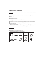
Accessories
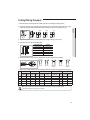
◆ The following accessories are supplied with the indoor unit.
5IFUZQFBOERVBOUJUZNBZEJòFSEFQFOEJOHPOUIFTQFDJöDBUJPOT
Pattern sheet (1) Thermal insulation Thermal insulation Thermal insulation Flexible hose clamp (1)
TQPOHF"
sponge B (1)
sponge C (1)
Flexible hose (1)
4
$BCMFUJF
user manual (1)
Installation (1)
manual
Conduit bracket (1)
Deciding
on where to install the indoor unit
AA
Indoor unit
ENGLISH
◆ There must be no obstacles near the air inlet and outlet.
◆ Install the indoor unit on a ceiling that can support its weight.
◆ .BJOUBJOTVóDJFOUDMFBSBODFBSPVOEUIFJOEPPSVOJU
◆ Make sure that the water dripping from the drain hose runs away correctly and safely.
◆ 5IFJOEPPSVOJUNVTUCFJOTUBMMFEJOUIJTXBZUIBUUIFZBSFPVUPGQVCMJDBDDFTT/PUUPVDIBCMFCZUIFVTFST
t *GZPVJOTUBMMUIFDBTTFUUFUZQFJOEPPSVOJUPOUIFDFJMJOHXJUIIVNJEJUZPWFSZPVNVTUBQQMZFYUSBNNPG
polyethylene foam or other insulation with similar material on the body of the indoor unit.
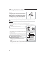
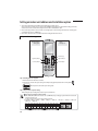
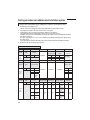
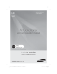
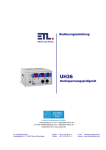
Space requirements for indoor unit
ore
m) or m
(1500m
h
c
in
.1
59
59
.1i
nc
h(1
50
0m
m)
59
.1i
nc
h(1
50
0m
m)
or
mo
re
or
mo
re
or more
0mm)
0
5
(1
h
59.1inc
%
#
"
&
$
Thickness: more than 0.39inch(10mm)
unit: inch (mm)
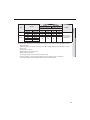
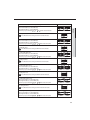
"
B
C
D
&
15.75*7.48
(400*190)
15.75*7.48
(400*190)
15.75*7.48
(400*190)
15.75*7.48
(400*190)
21.65*21.65
(550*550)
◆*OTVMBUFUIFFOEPGUIFQJQFBOETPNFDVSWFEBSFBCZVTJOHTFQBSBUFJOTVMBUPS
◆Insulate the discharge and suction part at the same time when you insulate connection duct.
5
Deciding
on where to install the indoor unit
AA
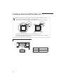
t 5 IFVOJUTNVTUCFJOTUBMMFEBDDPSEJOHUPEJTUBODFTEFDMBSFEJOPSEFSUPQFSNJUBDDFTTJCJMJUZGSPNFBDITJEF
either to guarantee correct operation of maintenance or repairing products.
5IFVOJUTQBSUTNVTUCFSFBDIBCMFBOESFNPWBCMFDPNQMFUFMZVOEFSTBGFUZDPOEJUJPOGPSQFPQMFPSUIJOHT
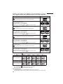
❈The appearance of the unit maybe different from the picture depending on the model.
t %POPUIPMEUIFEJTDIBSHFXIJMFDBSSZJOHUIFJOEPPSVOJUUPBWPJEUIFQPTTJCJMJUZPGCSFBLBHF:PVNVTUIPMEUIF
hanger plate on the corner and carry the indoor unit.
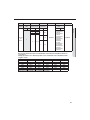
Required space for an indoor unit installation
59.1inch
(1500mm)
or more
A$NN
59.1inch(1500mm) or more
0.67inch
(17mm) 0.79inch
(20mm)
Obstruction
6
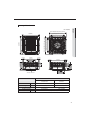
C
11.69"(297mm)
/FUEJNFOTJPO
22.64"*9.84"*22.64"
(575mm*250mm*575mm)
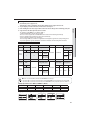
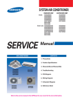
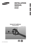
Drawing of the indoor unit
ENGLISH
Unit : inch(mm)
22.03~24.80(585~630) (Ceiling opening)
26.38(670)
1.87(47.5)
22.64(575)
1.87(47.5)
2.72(69)
6.30(160)
8.07(205) 1.69(43)
8.82(224)
1.87(47.5)
4.72(120)
22.64(575)
11.81(300)
7.87(200)
11.61(295)
9.84(250)
1.87(47.5)
19.69(500)(Suspension position)
26.38(670)
22.03~24.80(585~630)(Ceiling opening)
19.69(500)(Suspension position)
6.50(165)
9.80(249)
10.59(269)
Sub duct connection
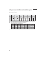
.0%&✴✴009/012✴✴
/FUEJNFOTJPO
inch(mm)
/FUXFJHIU
lb(kg)
Liquid pipe connection
(BTQJQFDPOOFDUJPO
Drain Hose connection inch(mm)
✴✴018✴✴
22.64x9.84x22.64 (575x250x575)
22.64x9.84x22.64 (575x250x575)
25.13 (11.4)
26.01 (11.8)
ø1/4"(6.35mm)
ø3/8"(9.52mm)
ø1/2"(12.70mm)
OD : Ф1(25) , ID : Ф0.79(20)
7
Indoor
unit installation
AA
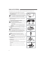
8IFOEFDJEJOHPOUIFMPDBUJPOPGUIFBJSDPOEJUJPOFSXJUIUIFPXOFSUIFGPMMPXJOHSFTUSJDUJPOTNVTUCFUBLFOJOUPBDDPVOU
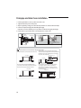
1. Determine the position of the pipe and drain hose hole as seen in the
picture and drill the hole with an inner diameter of 2.56inch(65mm) so that
it slants slightly downwards.
t Since the diagram is made of paper, it may shrink or stretch slightly
due to temperature or humidity. For this reason, before drilling the
holes maintain the correct dimensions between the markings.
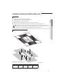
2. Insert bolt anchors, use existing ceiling supports or construct a suitable
support as shown in figure.
3. Install the suspension bolts depending on the ceiling type.
t & OTVSFUIBUUIFDFJMJOHJTTUSPOHFOPVHIUPTVQQPSUUIFXFJHIUPGUIF
indoor unit. Before hanging the unit,
test the strength of each attached suspension bolt.
t *GUIFMFOHUIPGTVTQFOTJPOCPMUJTNPSFUIBOGUN
JUJTSFRVJSFE
UPQSFWFOUWJCSBUJPO
t 5IFEJTUBODFCFUXFFOBTVTQFOTJPOCPMUBOEUIFUPQPGCSBDLFUJO
indoor unit) not exceed 0.98inch(25mm)(between indoor pipe and
hanger plate).
Concrete
Insert
Hole in anchor
Hole in plug
4VTQFOTJPOCPMU.
GJFMETVQQMZ
Ceiling support
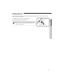
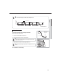
4. Screw eight nuts to the suspension bolts making space for hanging the
indoor unit.
t : PVNVTUJOTUBMMBMMUIFTVTQFOTJPOSPET
t *UJTJNQPSUBOUUPMFBWFTVóDJFOUTQBDFJOUIFGBMTFDFJMJOHUPBMMPX
access for maintenance or repairs to the drainage pipe connection,
UIFSFGSJHFSBOUQJQFDPOOFDUJPOPSUPSFNPWFUIFVOJUJGOFDFTTBSZ
5. Hang the indoor unit to the suspension bolts between two nuts.
t 1JQJOHNVTUCFMBJEBOEDPOOFDUFEJOTJEFUIFDFJMJOHXIFO
suspending the unit. If the ceiling is already constructed, lay the
piping into position for connection to the unit before placing the unit
inside the ceiling.
6. Screw the nuts to suspend the unit. Cut a pad stopper and place it on the
bracket at this time.
Pad stopper
Bracket
7. Adjust the unit to the appropriate position considering the installation area
for the front panel.
1) Place the pattern sheet on the indoor unit.
"EKVTUBTQBDFCFUXFFOUIFDFJMJOHBOEUIFJOEPPSVOJUCZVTJOHUIFHBVHF
of dimensions.
'JYUIFJOEPPSVOJUTFDVSFMZBGUFSBEKVTUJOHMFWFMPGUIFVOJUCZVTJOHB
MFWFMFS
3FNPWFUIFQBUUFSOTIFFUDPOOFDUUIFPUIFSDBCMFTBOEJOTUBMMUIFGSPOU
panel.
Indoor unit
Ceiling
0.67inch(17mm)
(BVHFPG
Dimensions
8
0.79inch(20mm)
Purging
the unit
AA
'SPNGBDUPSZUIFVOJUJTTVQQMJFEBOETFUXJUIBQSFDIBSHFPGOJUSPHFOHBTJOTFSUHBT
5IFSFGPSFBMMJOTFSUHBTNVTUCFQVSHFE
before connecting the assembly piping.
3&46-5"MMJOFSUHBTFTDBQFTGSPNUIFJOEPPSVOJU
t 5 PQSFWFOUEJSUPSGPSFJHOPCKFDUTGSPNHFUUJOHJOUPUIFQJQFTEVSJOH
JOTUBMMBUJPOEP/05SFNPWFUIFQJODIQJQFDPNQMFUFMZVOUJMZPVBSF
ready to connect the piping.
Liquid refrigerant
port
ENGLISH
Unscrew the pinch pipe at the end of each refrigerant pipe.
(BTSFGSJHFSBOUQPSU
9
Connecting the refrigerant pipe
There are two refrigerant pipes of different diameters :
◆ "TNBMMFSPOFGPSUIFMJRVJESFGSJHFSBOU
◆ "MBSHFSPOFGPSUIFHBTSFGSJHFSBOU
◆ The inside of copper pipe must be clean & has no dust
1. Remove the pinch pipe on the pipes and connect the assembly pipes to each pipe, tightening the nuts, first manually
and then with a torque wrench, a spanner applying the following torque.
Outer Diameter (D) 5PSRVFGUtMC/tN
Refrigerant oil
Torque wrench
Spanner
Flare nut
Union
ø1/4inch(6.35mm)
ø3/8inch(9.52mm)
ø1/2inch(12.70mm)
ø5/8inch(15.88mm)
ø3/4inch(19.05mm)
13.3(18)
31.0(42)
40.6(55)
47.9(65)
73.8(100)
t *GUIFQJQFTNVTUCFTIPSUFOFESFGFSUPQBHF
2. Must use insulator which is thick enough to cover the refrigerant tube to
protect the condensate water on the outside of pipe falling onto the floor
and the efficiency of the unit will be better.
3. Cut off any excess foam insulation.
4. Be sure that there must be no crack or wave on the bended area.
5. It would be necessary to double the insulation thickness(10mm or more)
to prevent condensation even on the insulator when if the installed area is
warm and humid.
6. Do not use joints or extensions for the pipes that connect the indoor and outdoor unit. The only permitted connections
are those for which the units are designed.
t $
POOFDUUIFJOEPPSBOEPVUEPPSVOJUTVTJOHQJQFTXJUIøBSFEDPOOFDUJPOTOPUTVQQMJFE
'PSUIFMJOFTVTF
JOTVMBUFEVOXFMEFEEFHSFBTFEBOEEFPYJEJ[FEDPQQFSQJQF$V%)1UZQFUP*40PS6/*&/
TVJUBCMF
GPSPQFSBUJOHQSFTTVSFTPGBUMFBTUL1BBOEGPSBCVSTUQSFTTVSFPGBUMFBTUL1B$PQQFSQJQFGPSIZESP
sanitary applications is completely unsuitable.
t ' PSTJ[JOHBOEMJNJUTIFJHIUEJòFSFODFMJOFMFOHUINBYCFOETSFGSJHFSBOUDIBSHFFUD
TFFUIFPVUEPPSVOJU
installation manual.
t "
MMSFGSJHFSBOUDPOOFDUJPONVTUCFBDDFTTJCMFJOPSEFSUPQFSNJUFJUIFSVOJUNBJOUFOBODFPSSFNPWJOHJUDPNQMFUFMZ
10
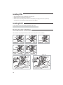
Cutting/Flaring the pipes
1. Make sure that you have the required tools available. (pipe cutter, reamer, flaring tool and pipe holder)
2. If you wish to shorten the pipes, cut it with a pipe cutter, taking care to ensure that the cut edge remains at a 90° angle
with the side of the pipe. Refer to the illustrations below for examples of edges cut correctly and incorrectly.
Oblique
Rough
ENGLISH
Pipe
cutter
Burr
Pipe
3. To prevent any gas from leaking out, remove all burrs at the cut edge of the pipe, using a reamer.
4. Slide a flare nut on to the pipe and modify the flare.
Pipe
Flare
Outer Diameter (D)
Depth (A)
ø1/4inch(6.35mm)
ø3/8inch(9.52mm)
ø1/2inch(12.70mm)
ø5/8inch(15.88mm)
ø3/4inch(19.05mm)
0.051inch(1.3mm)
0.071inch(1.8mm)
0.079inch(2.0mm)
0.087inch(2.2mm)
0.087inch(2.2mm)
5. Check that the flaring is correct, referring to the illustrations below for examples of incorrect flaring.
Correct
Inclined
Damaged
Surface
Cracked
6OFWFO
Thickness
6. Align the pipes and tighten the flare nuts first manually and then with a torque wrench, applying the following torque.
Flare nut
7BMWF 8SFODI
GUtMC
[inch(mm)] /tN
1/4" 0.67(17) 13.3(18)
3/8" 0.87(22) 31.0(42)
1/2" 1.02(26) 40.6(55)
5/8" 1.14(29) 47.9(65)
3/4" 1.42(36) 73.8(100)
7BMWFDBQ
8SFODI
GUtMC
[inch(mm)] /tN
0.91(23) 14.8(20)
0.91(23) 14.8(20)
1.14(29) 29.5(40)
1.14(29) 29.5(40)
1.50(38) 29.5(40)
Pressure port cap
8SFODI
GUtMC
[inch(mm)]
/tN
0.71(18) 11.8~13.3(16~18)
0.71(18) 11.8~13.3(16~18)
0.71(18) 11.8~13.3(16~18)
0.71(18) 11.8~13.3(16~18)
0.71(18) 11.8~13.3(16~18)
7BMWFOFFEMF
Pressure port
8SFODI
GUtMC 8SFODI
GUtMC
[inch(mm)]
/tN
[inch(mm)] /tN
"MMFOIFY
6.6(9)
0.25(0.34)
"MMFOIFY
6.6(9)
0.25(0.34)
"MMFOIFY
9.6(13)
0.25(0.34)
"MMFOIFY
9.6(13)
0.25(0.34)
"MMFOIFY
9.6(13)
0.25(0.34)
t *GUIFQJQFTSFRVJSFCSB[JOHFOTVSFUIBU0'/0YZHFO'SFF/JUSPHFO
JTøPXJOHUISPVHIUIFTZTUFN
t /JUSPHFOCMPXJOHQSFTTVSFSBOHFJT_.1B
11
Performing
leak test & insulation
AA
Leak test
To identify potential gas leaks on the indoor unit, inspect the connection area
of each refrigerant pipe using a leak detector for R-410A.
Before recreating the vacuum and recirculating the refrigerant gas, it is
advisable to pressurize the whole system with nitrogen (using a cylinder with
pressure reducer) at a pressure above 40 bar in order to immediately detect
leaks on the refrigerant fittings.
Made vacuum for 15 minutes and pressurising system with nitrogen.
t *GUIFQJQFTSFRVJSFCSB[JOHFOTVSFUIBU0'/0YZHFO'SFF/JUSPHFO
JTøPXJOHUISPVHIUIFTZTUFN
Insulation
Once you have checked that there are no leaks in the system, you can insulate the piping and hose.
1 To avoid condensation problems, place T0.511inch(13mm) or thicker Acrylonitrile Butadien Rubber separately around each
refrigerant pipe.
/PHBQ
t "MXBZTNBLFUIFTFBNPGQJQFTGBDFVQXBSET
/#35JODINN
PSUIJDLFS
2 Wind insulating tape around the pipes and drain hose avoiding to compress
the insulation too much.
3 Finish wrapping insulating tape around the rest of the pipes leading to the outdoor unit.
4 The pipes and electrical cables connecting the indoor unit with the outdoor
unit must be fixed to the wall with suitable ducts.
t "
MMSFGSJHFSBOUDPOOFDUJPONVTUCFBDDFTTJCMFJOPSEFSUPQFSNJU
FJUIFSVOJUNBJOUFOBODFPSSFNPWJOHJUDPNQMFUFMZ
*OTVMBUJPODPWFSQJQF
Insulation pipe
Indoor unit
#FTVSFUPPWFSMBQ
the insulation
5 Select the insulation of the refrigerant pipe.
◆ Insulate the gas side and liquid side pipe referring to the thickness
t .VTUöUUJHIUMZBHBJOTU
according to the pipe size.
body without any gap.
◆ *OEPPSUFNQFSBUVSFPG¡'¡$
BOEIVNJEJUZPGMFTTUIBOJTUIFTUBOEBSE
condition.
If installing in a high humidity condition, use one grade thicker insulator by referring to the table below.
*GJOTUBMMJOHJOBOVOGBWPSBCMFDPOEJUJPOTVTFUIJDLFSPOF
◆*OTVMBUPSTIFBUSFTJTUBODFUFNQFSBUVSFTIPVMECFNPSFUIBO¡'¡$
12
Pipe
(BTQJQF
Remarks
ENGLISH
Liquid pipe
Insulation Type (Heating/Cooling)
Standard
High humidity
Pipe size
[86°F(30°C), less than 85%] [86°F(30°C), over 85%]
EPDM, NBR
inch
mm
inch
mm
inch
mm
Ø6.35~9.52
9t
3/8
9t
3/8
Ø1/4~3/8
Ø1/2~3/4
Ø12.7~19.05
13t
1/2
13t
1/2
Ø1/4
Ø6.35
13t
1/2
19t
3/4
Ø9.52
Ø3/8
Ø1/2
Ø12.70
19t
3/4
25t
1
Ø5/8
Ø15.88
Ø3/4
Ø19.05
Internal tempera
ture is higher than
248°F(120°C)
◆ 8IFOJOTUBMMJOHJOTVMBUJPOJOQMBDFTBOEDPOEJUJPOTCFMPXVTFUIFTBNFJOTVMBUJPOUIBUJTVTFEGPSIJHIIVNJEJUZDPOEJUJPOT
(FPMPHJDBMDPOEJUJPO
)JHIIVNJEJUZQMBDFTTVDIBTTIPSFMJOFIPUTQSJOHOFBSMBLFPSSJWFSBOESJEHFXIFOUIFQBSUPGUIFCVJMEJOHJTDPWFSFECZ
earth and sand.)
0QFSBUJPOQVSQPTFDPOEJUJPO
3FTUBVSBOUDFJMJOHTBVOBTXJNNJOHQPPMFUD
#VJMEJOHDPOTUSVDUJPODPOEJUJPO
5IFDFJMJOHGSFRVFOUMZFYQPTFEUPNPJTUVSFBOEDPPMJOHJTOPUDPWFSFE
e.g. The pipe installed at a corridor of a dormitory and studio or near an exit that opens and closes frequently.
5IFQMBDFXIFSFUIFQJQFJTJOTUBMMFEJTIJHIMZIVNJEEVFUPUIFMBDLPGWFOUJMBUJPOTZTUFN
13
AA
Drainpipe
and drain hose installation
1 Push the supplied drain hose as far as possible over the drain socket.
2 Tighten the metal clamp as shown in the picture.
3 Wrap the supplied large sealing pad over the metal clamp and drain hose to insulate and fix it with clamps.
4 Insulate the complete drain piping inside the building (field supply).
If the drain hose cannot be sufficiently set on a slope, fit the hose with drain raising piping (field supply).
5 Push the drain hose up to insulation when connecting the drain hose to drain socket.
Metal clamp
Drain socket
Drain hose
Drain piping
5JHIUFOUIFQSPWJEFENFUBMDMBNQUP
make sure that fifteen holes are able to
be seen at least.
A-A’
Large sealing pad
"JSWFOUJMBUJPO
11.8inch(300mm) or less
0.79inch(20mm)
or more
1/100 or more
#BOEKPJOU
Ceiling
%POPUHJWFUIFIPTFBOEVQXBSEHSBEJFOUBGUFSUIF
DPOOFDUJPOQPSU5IJTXJMMDBVTFXBUFSUPøPXCBDLXBSET
when the unit is stopped, resulting in water leaks.
Under gradient
Drain hose
Ceiling
Do not apply force to the piping on the unit side when
connecting the drain hose. The hose should not be
allowed to hang loose from its connection to the unit.
Fasten the hose to a wall, frame or other support as close
to the unit as possible.
Support pieces
3.28~4.92ft(1~1.5m)
1/100 or more
Ceiling
14
21.7inch(550mm) or less
Check that the indoor unit is level with the ceiling by using the leveler.
If it is necessary to increase the height of the drainpipe,
*OTUBMMBJSWFOUJMBUJPOUPESBJODPOEFOTBUFXBUFSTNPPUIMZ
install the drainpipe straightly within 11.8inch(300 mm) from
the drain hose port. If it is raised higher than 21.7inch(550
mm), there can be water leaks.
Ceiling
ENGLISH
"JSWFOUJMBUJPO
1/100 or
more slope
3.9inch(100mm)
or more
t *GBDPODFOUSBUFEESBJOQJQFJTJOTUBMMFESFGFSUPUIFöHVSFCFMPX
Concentrated drain pipe
Testing the drainage
8BUFSMFBLBHF
check part
You should test the drainage after completing the installation.
Prepare a little water about 2.0 liters.
1 Turn the cover drain pump, then pull it out.
Hose
2 Pour water into the indoor unit as shown in figure.
t *GZPVEPOPUQPVSXBUFSJOTJEFUIFXBUFSTVQQMZJOUBLFXBUFSNBZ
spill from the indoor unit.
3 Confirm that the water flows out through the drain hose.
t :PVDBODIFDLUIFESBJOBHFPOMZXIFOUIFBJSDPOEJUJPOFSJTJODPPM
mode.
4 Reassemble the cover drain pump.
15
AA
Installing DPM
▶ 8IFOJOTUBMMJOH%1.ZPVTIPVMETFUA%1.TFUUJOHUPUIFPVUEPPSVOJU
▶ If DPM model is not set, communication error may occur.
▶ 8IJMFUIFPVUEPPSVOJUJTUSBDLJOHUIFJOEPPSVOJUGPSPOFNJOVUFBGUFSUIFQPXFSTVQQMZJTUVSOFEPOUIFPQFSBUJPONBZ
stop if the remote control reception signal of the installed indoor unit is different.
Installing MULTI
If using a multi system, refer to the manual supplied with the outdoor unit.
Bushing bracket installation
*GUIFDPOEVJUUVCFJTVTFECVTIJOHCSBDLFUNVTUCFJOTUBMMFEBTTIPXOJOUIFQJDUVSFUPöYUIFDPOEVJUUVCF
1
2
3
Push
4
5
Click
1 conduit tube
16
2 conduit tubes
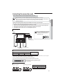
Connecting the connection cord
If using a multi system, refer to the manual supplied with the outdoor unit.
The indoor unit is powered by the outdoor unit by means of a H07 RN-F connection cable (or a more power model),
with insulation in synthetic rubber and jacket in polychloroprene(neoprene), in accordance with the requirements of standard EN 60335-2-40.
1. Remove the screw on the electrical component box and remove the cover plate.
2. Route the connection cord through the side of the indoor unit and connect the cable to terminals; refer to the figure below.
3. Route the other end of the cable to the outdoor unit through the ceiling & the hole on the wall.
4. Reassemble the electrical component box cover, carefully tightening the screw.
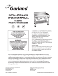
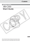
Wiring diagram
1 phase
WARNING
F4
L1
In case of extending the electric wire, please
DO NOT use a round-shaped pressing socket.
- Incomplete wire connections can cause
electric shock or a fire.
F3
L2
V2
Indoor Unit
V1
F2
F1
F3
L1 L2 L1 L2
Indoor Power
L1
L2
F4
V1
V2
Wired Remote
Controller(Optional)
F1 F2 F1 F2
Main power cable Communication cable
Outdoor Unit
Between Indoor and Outdoor Connection cable Specifications(Common in use)
Indoor Power supply
Power Supply
7_)[
.BY.JO7
Indoor Power cable
0.75~1.5mm²,3wires
Communication Cable
0.75~1.5mm²,2wires
J Power Supply cords of parts of appliances for outdoor use shall not be lighter than polychloroprene sheathed flexible cord. (Code designation
*&$*&$$&/&-&$)3/'PS*&$*&$$&/&-&$)3/'
J 4DSFXTPOUFSNJOBMCMPDLNVTUOPUCFVOTDSFXFEXJUIUIFUPSRVFMFTTUIBOLHGtDN
J 4JODFJUIBTUIFFYUFSOBMQPXFSTVQQMZSFGFSUPUIFPVUEPPSVOJUJOTUBMMBUJPONBOVBMGPS."*/108&3
8IFOJOTUBMMJOHUIFJOEPPSVOJUJOBDPNQVUFSSPPNVTFUIF
double shielded(Tape aluminum / polyester braid + copper)
cable of FROHH2R type.
Terminal Block SPEC (Indoor)
$0..6/*$"5*0/.4$3&8
13
7.5
18
11
9.0
5JHIUFOJOH5PSRVFGUtMCLHGtDN
M3.5
(0.58~0.72) 8.0~10.0
M4
(0.87~1.08) 12.0~15.0
13.8
"$108&3.4$3&8
17
ENGLISH
t "MXBZTSFNFNCFSUPDPOOFDUUIFSFGSJHFSBOUQJQFTCFGPSFQFSGPSNJOHUIFFMFDUSJDDPOOFDUJPOT
8IFOEJTDPOOFDUJOHUIFTZTUFNBMXBZTEJTDPOOFDUUIFFMFDUSJDDBCMFTCFGPSFEJTDPOOFDUJOHUIFSFGSJHFSBOUQJQFT
t "MXBZTSFNFNCFSUPDPOOFDUUIFBJSDPOEJUJPOFSUPUIFHSPVOEJOHTZTUFNCFGPSFQFSGPSNJOH
the electric connections.
Setting
an indoor unit address and installation option
AA
▶ Set the indoor unit address and installation option with remote controller option.
4FUUIFFBDIPQUJPOTFQBSBUFMZTJODFZPVDBOOPUTFUUIF"%%3&44TFUUJOHBOEJOEPPSVOJUJOTUBMMBUJPOTFUUJOHPQUJPOBUUIF
TBNFUJNF:PVOFFEUPTFUUXJDFXIFOTFUUJOHJOEPPSVOJUBEESFTTBOEJOTUBMMBUJPOPQUJPO
▶ Please use the proper wireless remocon which can set 24 digit option code. Following is the instructions of setting option
DPEFXJUIXJSFMFTTSFNPDPOPG.3&)6
▶ Please refer to the wired remocon installation manual for setting with the wired remocon.
The procedure of setting option
Entering mode for
setting option
Option
setting mode
Mode change
High Temp Button
High Fan Button
Low Temp Button
Low Fan Button
Step 1. Entering mode to set option
1. 3FNPWFCBUUFSJFTGSPNUIFSFNPUFDPOUSPMMFS
2. Insert batteries and enter the option setting mode while pressing High Temp button and Low Temp button
3.
.
$IFDLJGZPVIBWFFOUFSFEUIFPQUJPOTFUUJOHTUBUVT
Step 2. The procedure of option setting
"GUFSFOUFSJOHUIFPQUJPOTFUUJOHTUBUVTTFMFDUUIFPQUJPOBTMJTUFECFMPX
0QUJPOTFUUJOHJTBWBJMBCMFGSPN4&(UP4&(
t 4&(4&(4&(4&(BSFOPUOFFEUPCFTFUBU.3%)5IFZBSFUIFQBHFPQUJPOTXIJDIXFSFVTFEBUUIF
QSFWJPVTPUIFSSFNPDPOT
t 4FUUIFFBDICJUPQUJPODPEFJOPSEFSFYDFQUQBHFPQUJPOT
'PSFYBNQMF4&(4&(4&(4&(4&(4&(4&(4&(
4&(4&(
4&( 4&( 4&( 4&( 4&( 4&( 4&( 4&( 4&( 4&( 4&( 4&(
0
X
X
X
X
X
1
X
X
X
X
X
4&( 4&( 4&( 4&( 4&( 4&( 4&( 4&( 4&( 4&( 4&( 4&(
2
X
X
X
X
X
3
X
X
X
X
X
18
0O4&(_
0ò4&(_
Option setting
will be selected in rotation.
4&(
4&(
4&(
4&(
4&(
4&(
4&(
4&(
4&(
4&(
4&(
4&(
ENGLISH
4FUUJOH4&(4&(PQUJPO
Press Low Fan button(∨
UPFOUFS4&(WBMVF
Press High Fan button(∧
UPFOUFS4&(WBMVF
&BDIUJNFZPVQSFTTUIFCVUUPO
…
Status
2. Setting Cool mode
1SFTT.PEFCVUUPOUPCFDIBOHFEUP$PPMNPEFJOUIF0/TUBUVT
4FUUJOH4&(4&(PQUJPO
Press Low Fan button(∨
UPFOUFS4&(WBMVF
Press High Fan button(∧
UPFOUFS4&(WBMVF
&BDIUJNFZPVQSFTTUIFCVUUPO
…
will be selected in rotation.
4. Setting Dry mode
1SFTT.PEFCVUUPOUPCFDIBOHFEUP%3:NPEFJOUIF0/TUBUVT
4FUUJOH4&(4&(PQUJPO
Press Low Fan button(∨
UPFOUFS4&(WBMVF
Press High Fan button(∧
UPFOUFS4&(WBMVF
&BDIUJNFZPVQSFTTUIFCVUUPO
…
will be selected in rotation.
6. Setting Fan mode
1SFTT.PEFCVUUPOUPCFDIBOHFEUP'"/NPEFJOUIF0/TUBUVT
4FUUJOH4&(4&(PQUJPO
Press Low Fan button(∨
UPFOUFS4&(WBMVF
Press High Fan button(∧
UPFOUFS4&(WBMVF
&BDIUJNFZPVQSFTTUIFCVUUPO
…
will be selected in rotation.
8. Setting Heat mode
1SFTT.PEFCVUUPOUPCFDIBOHFEUP)&"5NPEFJOUIF0/TUBUVT
4FUUJOH4&(4&(PQUJPO
Press Low Fan button(∨
UPFOUFS4&(WBMVF
Press High Fan button(∧
UPFOUFS4&(WBMVF
&BDIUJNFZPVQSFTTUIFCVUUPO
…
will be selected in rotation.
4FUUJOH"VUPNPEF
1SFTT.PEFCVUUPOUPCFDIBOHFEUP"650NPEFJOUIF0''TUBUVT
4FUUJOH4&(4&(PQUJPO
Press Low Fan button(∨
UPFOUFS4&(WBMVF
Press High Fan button(∧
UPFOUFS4&(WBMVF
&BDIUJNFZPVQSFTTUIFCVUUPO
…
will be selected in rotation.
19
Setting an indoor unit address and installation option
Option setting
Status
12. Setting Cool mode
Press Mode button to be change to Cool mode in the OFF status.
4FUUJOH4&(4&(PQUJPO
Press Low Fan button(∨
UPFOUFS4&(WBMVF
Press High Fan button(∧
UPFOUFS4&(WBMVF
&BDIUJNFZPVQSFTTUIFCVUUPO
…
will be selected in rotation.
4&(
4&(
4&(
4&(
4&(
4&(
4&(
4&(
14. Setting Dry mode
Press Mode button to be change to Dry mode in the OFF status.
4FUUJOH4&(4&(PQUJPO
Press Low Fan button(∨
UPFOUFS4&(WBMVF
Press High Fan button(∧
UPFOUFS4&(WBMVF
&BDIUJNFZPVQSFTTUIFCVUUPO
…
will be selected in rotation.
16. Setting Fan mode
Press Mode button to be change to Fan mode in the OFF status.
4FUUJOH4&(4&(PQUJPO
Press Low Fan button(∨
UPFOUFS4&(WBMVF
Press High Fan button(∧
UPFOUFS4&(WBMVF
&BDIUJNFZPVQSFTTUIFCVUUPO
…
will be selected in rotation.
18. Setting Heat mode
1SFTT.PEFCVUUPOUPCFDIBOHFUP)&"5NPEFJOUIF0''TUBUVT
4FUUJOH4&(4&(NPEF
Press Low Fan button(∨
UPFOUFS4&(WBMVF
Press High Fan button(∧
UPFOUFS4&(WBMVF
&BDIUJNFZPVQSFTTUIFCVUUPO
…
will be selected in rotation.
Step 3. Check the option you have set
"GUFSTFUUJOHPQUJPOQSFTT
Option
button to check whether the option code you input is correct or not.
<4&(>
<4&(>
<4&(>
<4&(>
<4&(>
<4&(>
<4&(>
<4&(>
<4&(>
<4&(>
Remote Controller Display
Option
Remote Controller Display
Step 4. Input option
Press operation button
with the direction of remote control for set.
For the correct option setting, you must input the option twice.
Step 5. Check operation
3FTFUUIFJOEPPSVOJUCZQSFTTJOHUIF3&4&5CVUUPOPGJOEPPSVOJUPSPVUEPPSVOJU
2. Take the batteries out of the remote controller and insert them again and then press the operation button.
20
Setting an indoor unit address (MAIN/RMC)
4&(
Option
&YQMBOBUJPO
1"(&
4&(
.0%&
Indication Details Indication Details
Indication
and Details
0
4&(
Option
&YQMBOBUJPO
Indication
Details
0
/P.BJO
address
1
Main address
setting mode
4&(
1"(&
4&(
4&(
The unit digit of an
indoor unit
4&(
Indication
3&4&37&%
Indication
Details
0
/P3.$BEESFTT
1
RMC address
setting mode
1
3&4&37&%
4&(
Details
_"$/
_"+/
Setting RMC address
3&4&37&%
4&(
Setting Main address
"
Indication Details
Indication
and Details
4&(
ENGLISH
1. Check whether power is supplied or not.
- When the indoor unit is not plugged in, there should be additional power supply in the indoor unit.
2. The panel(display ) should be connected to an indoor unit to receive option.
3. Before installing the indoor unit, assign an address to the indoor unit according to the air conditioning system plan.
4. Assign an indoor unit address by wireless remote controller.
5IFJOJUJBMJOEPPSVOJU"%%3&44JTTFUBT."*/3.$
4FU.BJOBOE3.$"EESFTTPOMZUIFTFUUJOHJTSFRVJSFE
5IFSFJTOPOFFEUPBTTJHOUIFJOEPPSVOJU.BJO"EESFTTJGUIFPVUEPPSVOJUJTBEESFTTJOHBVUPNBUJDBMMZ
The indoor unit Main address will follow the outdoor unit's automatically.
"TTJHOEJHJUXIFOTFUUJOHUIFJOEPPSVOJUBEESFTT
/POFFEUPBTTJHO4&(XIJDIBSFOPOBQQMJDBCMF&WFOUIPVHIUIPTFTFHNFOUTBSFTFUUIFZXJMMCFJHOPSFE
*GZPVTFUUIFBQQMJDBCMFTFHNFOUTXJUIOVNCFSTPUIFSUIBOUIFJOEJDJBUFEUIFJOJUJBMTFUUJOHXJMMCFNBJOUBJOFE
0QUJPO/P"9999999999999999999
"TJOHMF
digit
4&(
4&(
(SPVQ
channel(*16)
(SPVQBEESFTT
Indication Details
Indication
Details
RMC2
0~F
3&4&37&%
RMC1
0~2
4&("+/NPEFMTTIPVMEDIFDLNBYJNVNJOTUBMMBUJPOJOEPPSVOJUOVNCFSPGPVUEPPSVOJU*OEPPS*OEPPS_
t8IFOi"w_w'wJTFOUFSFEUP4&(_UIFJOEPPSVOJU."*/"%%3&44JTOPUDIBOHFE
t*GZPVTFUUIF4&(BTUIFJOEPPSVOJUXJMMNBJOUBJOUIFQSFWJPVT."*/"%%3&44FWFOJGZPVJOQVUUIFPQUJPOWBMVFPG4&(
t*GZPVTFUUIF4&(BTUIFJOEPPSVOJUXJMMNBJOUBJOQSFWJPVT3.$"%%3&44FWFOJGZPVJOQVUUIFPQUJPOWBMVFPG4&(_
Example) If you want to set as "MAIN : 3, CHANNEL : 1, RMC : B",
4&(
4&(
4&(
4&(
0
"
1
4&(
4&(
4&(
4&(
1
1
assign option codes except SEG 1, 7 which are page options.
4&(
4&(
1
4&(
3
4&(
B
21
Setting
an indoor unit address and installation option
AA
Setting an indoor unit installation option (suitable for the condition of each installation location)
1. Check whether power is supplied or not.
- When the indoor unit is not plugged in, there should be additional power supply in the indoor unit.
2. The panel(display ) should be connected to an indoor unit to receive option.
3. Set the installation option according to the installation condition of an air conditioner.
- The default setting of an indoor unit installation option is “02000-100000-200000-300000”.
- Individual control of a remote controller(SEG20) is the function that controls an indoor unit individually when there is
more than one indoor unit.
- No need to assign SEG3, 6, 9, 10, 11, 16, 21, 22, 23, 24 which are non applicable. Even though those segments are set,
they will be ignored.
- If you set the applicable segments with numbers other than the indiciated, the initial setting will be maintained.
4. Set the indoor unit option by wireless remote controller.
Option No. : 02XXXX-1XXXXX-2XXXXX-3XXXXX
Option
4&(
4&(
&YQMBOBUJPO
1"(&
.0%&
Indication Indication Details Indication Details
and
0
2
Details
Option
4&(
4&(
&YQMBOBUJPO
1"(&
Use of drain pump
4&(
3&4&37&%
4&(
4&(
4&(
4&(
Use of external
temperature sensor
Use of central
control
RPM setting
compensation
Indication Details Indication Details
0
Disuse
0
Disuse
1
Use
1
Use
4&(
4&(
/PUVTFE
1. High ceiling mode
2. High ceiling kit
3. Low noise operation
mode
4&(
.BTUFS4MBWF
Indication Details Indication Details
Indication Details
3&4&37&%
3&4&37&%
3&4&37&%
0
Disuse
0
TMBWF
Indication
1
Use
1
master
and
1
Details
Use +
2
3minute
delay
Option
4&(
4&(
4&(
4&(
4&(
4&(
Use
of
external
Setting
the
output
/VNCFSPGIPVST
&YQMBOBUJPO
1"(&
41MBTNBJPO
Buzzer control
control
of external control
VTJOHöMUFS
Indication Details Indication Details Indication Details Indication Details Indication Details Indication Details
Mixed operation
Thermo
0
Disuse
0
control 1/Use
0
Disuse
0
2
1000 Hour
on
buzzer
Mixed operation
0/0''
Indication
control 1/Disuse
1
1
Control
and
of buzzer
2
Details
Mixed operation
OFF
Operation
2000
control 2/Use
2
1
1
Use
2
6
Control
on
Hour
buzzer
Mixed operation
8*/%08
control 2/Disuse
3
3
Control
of buzzer
4&(GPS"$/.PEFM/PUVTFEi.JYFEPQFSBUJPODPOUSPM*OEJDBUJPO/P/Pw
22
Indication
and
Details
4&(
1
2˚C
2
5˚C
4&(
3&4&37&%
3
4
Indoor 4
4&(
Motion detect
sensor
Indication Details
0.No Use (Factory Setting)
1.Standard Mode/Auto
Set OFF30 Min.
2.Standard Mode/Auto
Set OFF60 Min.
3.Standard Mode/Auto
Set OFF 120 Min.
4.Standard Mode/Auto
Set OFF 180 Min.
5.Premium Mode/
Auto Set OFF30
Min.6.Premium Mode/
Auto Set OFF60 Min.
7.Premium Mode/Auto
Set OFF 120 Min.
8.Premium Mode/Auto
Set OFF 180 Min.
4&(
ENGLISH
4&(
4&(
*OEJWJEVBMDPOUSPMPG
Heating
setting
&YQMBOBUJPO
1"(&
a remote controller
compensation
Indication Details Indication Details Indication Details
0 or 1 Indoor 1
2
Indoor 2
0
Disuse
3
Indoor 3
Option
3&4&37&%
X If you input a number other than 0~4 on the individual control of the indoor unit(SEG 20), the indoor is
set as "Indoor 1".
Example) If you want to set as "Exterior temperature sensor : USE, External control : USE, Number of hours
using filer : 2000hr",
4&(
4&(
4&(
4&(
0
2
1
4&(
4&(
4&(
4&(
1
0
4&(
4&(
4&(
4&(
2
1
0
4&(
4&(
4&(
4&(
3
0
assign option codes except SEG 1, 7, 13, 19 which are page options.
4&(
0
4&(
4&(
0
4&(
4&(
4&(
0
4&(
6
4&(
23
AA
Setting an indoor unit address and installation option
Changing a particular option
You can change each digit of set option.
Option
4&(
4&(
&YQMBOBUJPO
1"(&
.0%&
Indication
and
Details
Indication Details Indication
0
Details
D
4&(
4&(
4&(
4&(
The option mode 5IFUFOTEJHJUPGBO The unit digit of
you want to
PQUJPO4&(ZPVXJMM BOPQUJPO4&(ZPV 5IFDIBOHFEWBMVF
change
change
will change
Indication Details Indication Details Indication Details Indication Details
The
Option
5FOTEJHJU
Unit digit
0~F
0~9
0~9 changed 0~F
mode
PG4&(
PG4&(
WBMVF
t 8IFODIBOHJOHBEJHJUPGBOJOEPPSVOJUBEESFTTTFUUJOHPQUJPOTFUUIF4&(BTA"
t 8IFODIBOHJOHBEJHJUPGJOEPPSVOJUJOTUBMMBUJPOPQUJPOTFUUIF4&(BTA
Ex) When setting the 'buzzer control' into disuse status.
Option
24
4&(
4&(
&YQMBOBUJPO
1"(&
.0%&
Indication
0
D
4&(
4&(
4&(
The option 5IFUFOTEJHJUPG The unit digit of
mode you want BOPQUJPO4&( BOPQUJPO4&(
to change
you will change you will change
2
1
7
4&(
The changed
WBMVF
1
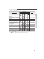
Troubleshooting
-&%MBNQEJTQMBZ
"COPSNBMDPOEJUJPOT
Operation
Timer
Filter
X
X
X
X
X
X
X
X
&SSPSPGIFBUFYDIBOHFSTFOTPSJOUIFJOEPPSVOJU
(Open/Short)
&SSPSPGGBONPUPSJOUIFJOEPPSVOJU
X
&SSPSPGUIFPVUEPPSUFNQFSBUVSFTFOTPS
&SSPSPGUIFDPOEFOTPSUFNQFSBUVSFTFOTPS
&SSPSPGUIFEJTDIBSHFUFNQFSBUVSFTFOTPS
/PDPNNVOJDBUJPOGPSNJOVUFTCFUXFFO
indoor and outdoor unit
(communication error for more than 2minutes)
X
&SSPSPGPVUEPPSVOJU
X
Detection of the float switch
X
X
X
X
X
Remarks
ENGLISH
Power reset
&SSPSPGUFNQFSBUVSFTFOTPSJOUIFJOEPPSVOJU
(Open/Short)
Defrost
X
X
&&130.FSSPS
X
&&130.PQUJPOFSSPS
Motion detect sensor error
Mixed operation error
● On
Flickering
X
X
X
X
X
X Off
◆ *GZPVUVSOPGGUIFBJSDPOEJUJPOFSXIFOUIF-&%JTGMJDLFSJOHUIF-&%JTBMTPUVSOFEPGG
25
Cassette Type Series
AJ✴✴✴JNNDCH
Air Conditioner
installation manual
This manual is made with 100% recycled paper.
imagine the possibilities
Thank you for purchasing this Samsung product.
EN ES FR DB68-04991A-00