1
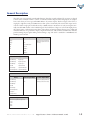
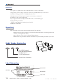
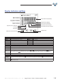
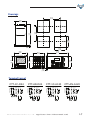
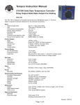
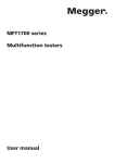
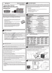
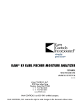
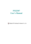
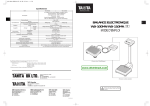
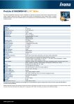
GETTING STARTED
CHAPTER
1
In This Chapter...
Manual Overview . . . . . . . . . . . . . . . . . . . . . . . . . . . . . . . . . . . . . . . . . . . . . . . . . . .1-2
Purpose of this Manual . . . . . . . . . . . . . . . . . . . . . . . . . . . . . . . . . . . . . . . . . . . . . . .1-2
Technical Support . . . . . . . . . . . . . . . . . . . . . . . . . . . . . . . . . . . . . . . . . . . . . . . . . .1-2
Special Symbols . . . . . . . . . . . . . . . . . . . . . . . . . . . . . . . . . . . . . . . . . . . . . . . . . . . .1-2
General Description . . . . . . . . . . . . . . . . . . . . . . . . . . . . . . . . . . . . . . . . . . . . . . . . .1-3
Unpacking . . . . . . . . . . . . . . . . . . . . . . . . . . . . . . . . . . . . . . . . . . . . . . . . . . . . . . . .1-4
Model Number Explanation . . . . . . . . . . . . . . . . . . . . . . . . . . . . . . . . . . . . . . . . . . .1-4
Label Information . . . . . . . . . . . . . . . . . . . . . . . . . . . . . . . . . . . . . . . . . . . . . . . . . . .1-4
Display Indicators and Keys . . . . . . . . . . . . . . . . . . . . . . . . . . . . . . . . . . . . . . . . . . .1-5
General Specifications . . . . . . . . . . . . . . . . . . . . . . . . . . . . . . . . . . . . . . . . . . . . . . .1-6
Drawings . . . . . . . . . . . . . . . . . . . . . . . . . . . . . . . . . . . . . . . . . . . . . . . . . . . . . . . . .1-7
Terminal Layout . . . . . . . . . . . . . . . . . . . . . . . . . . . . . . . . . . . . . . . . . . . . . . . . . . . .1-7
w w w. a u to m at i o n d i re c t . c o m
Digital Counter / Timer / Tach User Manual, 1st Ed.
1-1
Overview of this Publication
Thank you for purchasing an AutomationDirect CTT Series Digital Counter / Timer / Tach. This manual shows
you how to install, program and maintain the unit.
Who Should Read This Manual
This manual contains important information for those who will install, maintain, and/or operate the
AutomationDirect CTT Series Digital Counter / Timer / Tach. It will provide the information you need to get and
keep your system up and running.
Technical Support
On the Web: support.automationdirect.com
Our technical support group is glad to work with you in answering your questions. If you cannot find the solution
to your particular situation, or, if for any reason you need additional technical assistance, please call technical
support at 770-844-4200. We are available weekdays from 9:00 a.m. to 6:00 p.m. Eastern Time.
We strive to make our manuals the best in the industry. We rely on your feedback to let us know if we are reaching
our goal.
We also encourage you to visit our web site where you can find technical and non-technical information about our
products and our company. Visit us at www.automationdirect.com.
Special Symbols
When you see the “exclamation mark” icon in the left-hand margin, the paragraph to
its immediate right will be a warning. This information could prevent injury, loss of
property, or even death (in extreme cases).
1-2
Digital Counter / Timer / Tach User Manual, 1st Ed.
1 - 80 0 - 633 - 0405
General Description
The CTT series is an extremely versatile multi-function device that is easily configured for operation as a digital
counter, timer, combination timer + counter, or tachometer. Both voltage and non-voltage inputs are accepted
from a wide variety of sensor types with NPN, PNP, or dry contact outputs. The first output on the CTT is a
single-pole, single-throw relay and NPN transistor that operate concurrently. The second CTT output can be
ordered as either a single-pole, double throw relay or NPN transistor. Parameters are easily set using the externally accessible DIP switches or the lockable keypad. The double-line, 6-digit, two-color LCD display shows
the counter, timer, or tachometer present values, setting values and menu parameters during set-up. Additional
individual indicators are provided for inputs, outputs and functions. The standard 1/16 DIN size, included
panel mounting clip and gasket make panel mounting a snap. The CTT is available in 120-240VAC and
24VDC powered models.
Counter Functions
Counter Input Modes
Counter Output Modes
Select from eleven (11) different
output modes (F, N, C, R, K, P, Q,
A, S, T, D)
1-Stage
Up
2-Stage
Down
Batch
Up / Command Down
Total
Up/ Down
Dual
Quadrature
Addition
Subtraction
Timer Functions (Up or Down)
Signal On Delay 1
Repeat Cycle
Signal On Delay 2
Repeat Cycle Hold
Signal Off Delay
Repeat Cycle 2
Signal On
Signal Cumulate
Power On Delay
Signal Twin On-Start
Power On Delay Hold
Signal Twin Off-Start
Timer + Counter
Timer Functions (Up or
Down)
Counter Input Modes
Signal On Delay 1
Up
Signal On Delay 2
Down
Counter Output Modes
Select from eight (8) different output modes (F, N, C, R, K, P, Q, A)
Signal Off Delay
Signal On
Power On Delay
Power On Delay Hold
Repeat Cycle
Repeat Cycle Hold
Tachometer Output Modes
Select from four (4) different output modes
2Lo/1Lo
2Lo/1Hi
2Hi/1Lo
2Hi/1Hi
w w w. a u to m at i o n d i re c t . c o m
Digital Counter / Timer / Tach User Manual, 1st Ed.
1-3
Features
-Can operate as a digital counter, timer, combination timer + counter or tachometer
-Accepts voltage and non-voltage inputs from a wide variety of NPN, PNP, or dry contact sensors
-Selectable counting speeds from 1 to 10,000 cycles per second
-Multiple transistor and relay outputs can operate as momentary or maintained
-Double-line, 6-digit, 2-color LCD display
-Easy configuration with externally accessible DIP switches or the lockable keypad
-Display decimal point selection
- Available in 120-240VAC and 24VDC powered models
-UL508 listed, CE marked
Unpacking
After receiving the CTT Counter/Timer/Tach, please check for the following:
• Make sure that the package includes the CTT Counter/Timer/Tachometer, the mounting bracket and
hardware, and the Quick Start Guide.
• Inspect the unit to insure it was not damaged during shipment.
• Make sure that the part number indicated on the label corresponds with the part number of your order.
Model Number Explanation
CTT-
AN-
D24
D24: 24VDC powered
A120: 100-240VAC powered
AN: NPN output 2
1C: SPDT relay output 2
Counter/Timer/Tachometer
Label Information
Input Specification
Model Number
Agency Approvals
MADE IN CHINA
1-4
Digital Counter / Timer / Tach User Manual, 1st Ed.
Country of Origin
1 - 80 0 - 633 - 0405
Display, Indicators and Keys
CTT
.com
AUTOMATIONDIRECT
Reset 2 indicator
Reset 1 indicator
PV(Present Value) display
Key protect 2 indicator
Key protect 1 indicator
SV(Set Value) display
Output 2 indicator
Output 1 indicator
Timer function indicator
Counter function indicator
Tachometer function indicator
Special function indicator
Lock key
Reset key
Up/Down key
Mode and number shift key
LCD Display and Indicators
RST 1/2
K/P 1/2
OUT 1/2
HMS
TOTAL
,.
´
Ä
BATCH
Light on when key-protected mode is enabled
SET 1 2
Light on when output is executing
TAC
Hour, minute, second, unit of timer, displayed in Timer function CNT
“Total Counting Mode” in Counter function
TMR
Light on when reset signal is detected
“Batch Counting Mode” in Counter
SV1, SV2 display
Light on in Tachometer function
Light on in Counter function
Light on in Timer function
Key Operation
Increase and decrease SV or change paramter settings
Left move 1 digit of the selected digit. The indicator of the selected digit will flash.
Save the set parameters or switch among functions.
LOCK
Prevent settings from being changed. Key-protected mode still works after the power is switched off. Press LOCK to enter key-protected mode. In non-key-protected
status, press LOCK to enter Lock 1, press LOCK again to enter Lock 2. Press Ä and ´ at the same time to disable key-protected mode. LoC1 (Lock 1) disables the functions of all keys. LoC2 (Lock 2) allows users to change SV and functions of RESET remain. LOCK only functions in non-key-protected status.
RESET
Clear and reset PV.
Operation
When the power is on, the timer/counter/tachometer is in the operation mode. Press ,. to change SV, or ´ to select digit to change. The indicator of the
selected digit will flash. After the change is made, press Ä to save the setting. If SV or paramters are not changed, press Ä once to switch between SET1 and
SET2.
Modes: Operation Mode and Configuration Mode
Ä in operation mode for more than 3 seconds to enter configuration mode. Press Ä once to switch among parameters. To return to operation mode, press
Configuration Press
Ä for more than 3 seconds.
w w w. a u to m at i o n d i re c t . c o m
Digital Counter / Timer / Tach User Manual, 1st Ed.
1-5
General Specifications
Digital Counter / Timer / Tachometer General Specifications
Input Power Requirements
Operation Voltage Range
Power Consumption
Power Source
Display
100 to 240 VAC 50/60 Hz
24 VDC
85 to 264 VAC
21.6 to 26.4 VDC
Less than 10VA
12VDC 앐10%, 100mA
Double-line, 6-digit LCD display (SV = 8mm, PV = 6mm)
NPN ON impedance 1K ohm max. ON residual voltage: 2V max.
PNP 4.5 to 30VDC, low level: 0 to 2VDC
Input Signal
Relay: SPST max. 250VAC, 5A (resistive load), 4A (inductive load); Transistor: NPN open collector. When 100mA @
30VDC, residual voltage = 1.5VDC max
Output 1
Output 2
CTT-1C-xxx
CTT-AN-xxx
Output Switching Time
Dielectric Strength
Vibration Resistance
Shock Resistance
Ambient Temperature
Storage Temperature
Altitude
IP Rating
Case Materials
Ambient Humidity
Memory Backup upon Power Failure
Conforming Wiring
Terminals
Permitted Torque
Agency Approvals
1-6
Relay: SPDT max. 250VAC, 5A (resistive load), 4A (inductive load)
Transistor: NPN open collector. When 100mA @ 30VDC, residual voltage = 1.5VDC max
2 milliseconds max
2000VAC 50/60Hz for 1 minute
Without damage: 10 ~ 55Hz, amplitude = 0.75mm, 3 axes for 2 hours
Without damage: drop 4 times, 300m/s² 3 edges, 6 surfaces and 1 corner
Digital Counter / Timer / Tach User Manual, 1st Ed.
+32°F to +122°F (0°C to +50°C)
-4°F to +149°F (-20°C to +65°C)
2000m or less
IP 66 (with proper enclosure installation)
Case = ABS Plastic, Lens = Polycarbonate
35% to 85% RH (non-condensing)
EEPROM writing up to 100,000 times; Memory duration: 10 years
0.25-1.65mm² (24 to 16 AWG)
0.5Nm (0.369 ft/lbs)
UL508 listed (E311366), cULus, CE marked
1 - 80 0 - 633 - 0405
Drawings
mm [inches]
65.00
[2.56]
44.80
[1.76]
60.00
[2.36]
79.35
[3.12]
45.00
[1.77]
6.35
[0.25]
45.00
[1.77]
47.85
[1.88]
79.35
[3.12]
44.80
[1.76]
.com
AUTOMATIONDIRECT
CTT
11
12
13
14
15
6
7
8
9
10
1
2
3
4
5
RST2
RST1
K/P2
K/P1
44.80
[1.76]
OUT2
47.85
[1.88]
OUT1
LOCK
44.80
[1.76]
RESET
MODE
6.35
[0.25]
Terminal Layout
13
RST1
RST2/
START
7
8
+12V
6
N.O.
0V
9
15
COM
10
COM
N.C.
1
14
2
4
3
5
11
12
13
RST1
RST2/
START
6
7
8
0V
LOAD
+V
2
3
+12V
1
14
0V
9
15
COM
10
CP1
11
12
13
RST1
RST2/
START
7
8
+12V
6
N.O.
4
5
CP2/
GATE
0V
14
15
0V
COM
9
10
COM
N.C.
1
OUT
1
LOAD N.O.
2
3
4
5
CTT-AN-A120
LOAD
12
13
14
CP1
11
RST1
RST2/
START
6
7
8
0V
LOAD
+V
2
3
+12V
1
OUT
1
N.O.
CP2/
GATE
0V
15
0V
COM
9
10
4
5
OUT
2
OUT
2
-
+
21.6 to
26.4 VDC
Load
OUT
2
w w w. a u to m at i o n d i re c t . c o m
-
+
21.6 to
26.4 VDC
AC100 to 240V
50/60Hz
Digital Counter / Timer / Tach User Manual, 1st Ed.
Load
OUT
2
S
12
CP1
CTT-1C-A120
POWER SOURCE
12VDC @ 100mA
11
CP2/
GATE
0V
OUT
1
LOAD N.O.
S
CP1
CTT-AN-D24
POWER SOURCE
12VDC @ 100mA
CP2/
GATE
0V
OUT
1
LOAD N.O.
POWER SOURCE
12VDC @ 100mA
POWER SOURCE
12VDC @ 100mA
CTT-1C-D24
AC100 to 240V
50/60Hz
1-7