1
Printed in Hong Kong
PA: OI-A8/EN-Apr.1307-V7.0
Features
WIRELESS PSTN
ALARM SYSTEM
100% wireless configuration, D.I.Y. Installation
Convenient operation by remote control
Support 60 wireless accessories
Built-in 1,000,000 RF codes combination maintains
high reliability
Simple accessory expansion by automatic recoding
Mute remote control at late night
Home mode by remote control
Built-in 100dB siren, deterring intruder on site
Store 6 alarm phone numbers
Simple operation by voice prompt menu
Remote arm, disarm and monitor by phone operation
Built-in 500mAh lithium battery enables 8-hour standby
Please read this instruction manual carefully before using.
Kindly keep this user manual for your reference when
necessary.
Table of Contents
Included Accessories
1~2
Alarm Response When Being Out of Home
16
Control Panel Layout
3~4
Remote Phone Control
17
Programming List
18
Phone Remote Control Instruction
19
Power on
Specifications
20
Connect PSTN Land Line
Wireless Remote Control
21~23
Wireless Door/Window Contact
24~27
Wireless PIR Motion Detector
28~34
Alarm Indicators Introductions
Preparation before Use
4
5~6
Installation
Connect and Clear Wireless Accessories
7~8
Connect Wireless Accessories
Connect Wireless Siren
Clear Wireless Accessories
Zone Setup of Wireless Accessories
System Setting
Enter Setup State
Program Ringing Time of the Siren
Program Exit Delay & Entry Delay
Enable Remote Phone Control
Disable Remote Phone Control
Set Internal Siren Volume
Change Password
Program Phone Numbers
Restore Default Settings
Exit Setup State
3
9
10~16
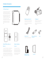
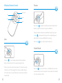
Included Accessories
CG-A8 Control Panel x 1
The control panel is known as the “heart and
brain” for alarm system, which is used for
receiving and processing signals from wireless
sensors and remote controls. Users can make
settings freely with the keypad. In case of
emergency, the panel rings on site and dials
the pre-stored alarm phone numbers
Wireless Remote Control x 2
AC Adapter x 1
The remote control is compact and portable; it
Supply power to the control panel via it. In
automatically. When users pick up the phone,
they are able to hear prompt voice and
choose to monitor on site or disarm the
system.
Wireless PIR Motion Detector x 1
Wireless Door/Window
Bracket x 1
Contact x 1
The wireless PIR Motion Detector is an intelligent passive
The Door/window contact can be
infrared motion sensor, designed to detect human
installed on doors, windows and any
movement within an approximate range of 6 to 8 meters
other objects that open and close. The
from the detector. The detector includes fuzzy logic to
sensor transmits signals to the control
minimize false alarms from unwanted heat sources. With
panel when a magnet mounted near
power saving feature, the detector will enter sleeping mode
the sensor is moved away.
after the second activation within 3 minutes to save power.
1
is convenient to carry it to arm, disarm, and
case of power failure, four backup
partially arm the alarm system and also send
batteries in the panel will support 15-hour
an emergency call.
working time.
Telephone Cable x 1
Wall-mounted bracket for
Connect the control panel and telephone
control panel
Double-sided tape for
Screws
User Manual
Door/Window Contact
2
Control Panel Layout
Table Stand
Panic Button
Power/Low Power LED Indicator
Tamper Switch
Setup/Connect LED Indicator
Arm State LED Indicator
Power On/Off
Zone LED Indicators
Battery Compartment
Alarm Indicators Introductions
Adaptor Interface
External Telephone
Line Interface
Connect Button
Alarm Type
Monitoring MIC
Setup Button
3
Tamper Alarm
Setup/Wireless Signal LED Indicator, system status
LED indicator and all zone LED indicators will flash
Normal Zone Alarm
The system status and triggered zone LED indicators
will flash
24-hour Zone Alarm
The system status LED indicator and LED indicator
and all zone LED indicators will flash
Emergency Call
System Status LED indicator and all zone LED
indicators will flash
Telephone Interface
Siren Interface
Indicator State
4
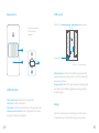
Preparation before Use
2. Connect PSTN Land Line
1. Power on
1
A8 is a PSTN alarm system which will auto dial the pre-stored phone
number when the system detects intruders. Please be sure the panel has
Plug the output connector of AC adapter into the adapter interface of
connected to PSTN land line to ensure safety.
control panel.
2
Plug the AC adapter to wall power socket.
3
Turn the power switch from OFF to ON.
1
Connect the PSTN Land Line provided by fixed telephone line operator to
2
Connect one end of provided telephone cable to the telephone interface
the PSTN Land Line interface on the panel.
on the panel, the other end to the telephone.
2
1
1
3
2
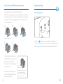
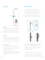
3. Installation
Fix the wall mounting bracket on the wall with screws.
Wedge the panel on the bracket, make sure they fit well.
5
6
Connect and Clear Wireless Accessories
Operation:
Connect Wireless Accessories
Press the Connect Button of the wireless siren for 0.5 second,
the Connect Button LED indicator lights on, and then press
the SOS Button on the control panel, the siren will be
connected after one beep is heard.
Testing: Press the Arm Button on the remote control, to make
sure that the internal siren and wireless siren both beep once,
Press {Connect
} button, the Connect LED indicator lights on,
then trigger the wireless accessory once. It will be connected after
the connection is successful. If not, the connection fails,
please reconnect them.
one beep and the LED indicator blacks out. Once two beeps are
heard, the accessory has been connected before.
Once the intruder is detected, both internal siren and wireless
siren will hoot to deter the illegal intruder. (The siren will be
Connect Wireless Siren
off in 5 minutes as the default setting). At the same time, the
alarm system will send SMS and auto dial to users.
The newly-added wireless siren can be used after
connecting to the control panel.
Clear Wireless Accessories
Press down the {Connect
} button until two beeps are heard.
All the connected accessories including wireless sirens will be cleared.
7
8
Zone Setup of Wireless Accessories
System Setting
The sensors can be set as A,B,C,D,E and 24-H zone.
Enter Setup State
Once the sensors are triggered, users can easily know which zone is
activated and where the intrusion is happened by the LED indicators
on the panel. See the following guide to set the jumpers on PCB
board of accessories.
A
B
C
Home Mode Zone
D
Hold {Setup
E
} button for 3 seconds till the voice prompt of
“System enters setup state successfully” is heard. At the same time,
the setup LED indicator lights on. The system enters setup state.
The door sensor is set at zone C
and the PIR motion detector is at
Home Mode Zone (Zone A).
Zones can be coded according to
your requirement.
After the zone is changed, the
detector should be reconnected
with the control panel.
9
24-H Zone
Note: It is recommended to
set smoke detector, gas
detector and outdoor beam
sensor at 24-H zone.
10
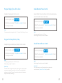
Program Ringing Time of the Siren
Example: Set ringing time to be 5 minutes
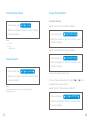
Enable Remote Phone Control
Example: Enable the remote phone control, and program ringing
times of automatic answer to be 8 times.
Enter setup state, input
1
5
When the voice prompt of “Operation succeeded” is heard,
Enter setup state, input
3
8
When the voice prompt of “Operation succeeded” is heard,
the setup is successful.
the setup is successful.
Note!
User may program the ringing time to be 1 ~ 9 minutes. Default setting: 5 minutes.
Note!
User may program the time to be 2-9 times.
Default setting: Remote phone control is disabled.
Program Exit Delay & Entry Delay
Example: Program exit delay & entry delay to be 60 seconds
Enter setup state, input
2
60
Enter setup state, input
3
When the voice prompt of “Operation succeeded” is heard,
When the voice prompt of “Operation succeeded” is heard,
the setup is successful.
the setup is successful.
Note!
User may program delay time to be 0~300 seconds.
Default setting: no delay. The value is 0.
Special tips!
Once the function is programmed, when you arm the system, the panel beeps
once every two seconds to remind the user to leave. The reminding rhythm
will speed up in the last 15 seconds. Once intruder is detected, the alarm and
dialing will be delayed accordingly.
11
Disable Remote Phone Control
Note!
Default setting: Remote phone control is disabled.
Special tips!
If user cannot remote control the system by phone, please make
sure the function of {Remote Phone Control} is enabled.
12
Set Internal Siren Volume
Program Phone Numbers
Store Phone Numbers
Enter setup state, input
4
(0~2)
Example: Store the 1st phone number as 12345678.
When the voice prompt of “Operation succeeded” is heard,
the setup is successful.
Enter setup state, input
1
12345678
When the voice prompt of “Operation succeeded” is heard,
Note!
"0” = Mute
"1" = Low
“2” = High (Default)
the setup is successful.
Example: Store the 2nd phone number as 23456789.
Enter setup state, input
Change Password
2
23456789
When the voice prompt of “Operation succeeded” is heard,
the setup is successful.
Enter setup state, input
9
new password
6 users’ phone numbers can be stored.
When the voice prompt of “Operation succeeded” is heard,
the setup is successful.
If the control panel uses an extension for dialing,
0
or 9
should
be added before the phone number.
Note!
The password must be any 4,5,or 6-digit code between 0 and 9.
Default password: 1234.
Example: Store the 1st phone number as 12345678.
Enter setup state, input
1
0
12345678
When the voice prompt of “Operation succeeded” is heard,
the setup is successful.
13
14
Exit Setup State
Delete Phone Numbers
Example: Delete the 1st phone number.
Under the setup state, press {setup
} button until 2 beeps
are heard, and the setup LED indicator blacks out, the system
Enter setup state, input
1
exits setup state.
When the voice prompt of “Operation succeeded” is heard,
the setup is successful.
Alarm Response When Being Out of Home
Example: Delete the 2nd phone number.
When the system detects intruders, the on-site siren will hoot
Enter setup state, input
immediately, and the control panel will auto dial the pre-stored
2
phone numbers.
When the voice prompt of “Operation succeeded” is heard,
the setup is successful.
The user can monitor the site and control the system by phone
when getting the alarm call.
Note! Delete all existing alarm phone numbers:
0
Restore Default Settings
Enter setup state, input
Note!
No need to input password to remote control the system when getting the alarm call.
0
When the voice prompt of “Operation succeeded” is heard,
the setup is successful.
Note!
All settings are restored to default; the password is restored to 1234.
The restoring programming will not affect stored phone numbers.
Also, it will not clear the connected accessories.
15
16
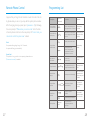
Remote Phone Control
Programming List
Suppose that you forget to arm the alarm or want to monitor the site
by phone when you are out, you may dial the system phone number.
After the ringing times you preset, input {password + #} by following
the voice prompt of “Please enter your access code”. Enter the state
of remote phone control once the voice prompt of “Correct code, you
can remote control the system now.” is heard.
Note!
No operation after getting through for 30 seconds,
the system will hang up automatically.
Special tips!
If the phone is hung up without voice prompt, please make sure
{Phone remote control} is enabled.
Description
Operation
Command
Remarks
Program Ringing
Time of the Siren
1 9
[9] Refers to the minutes that
the siren keeps alarming. User
can program to be 1~9 minutes.
Default setting:
5 minutes.
Program Exit Delay
& Entry Delay
2 60
[60] Refers to the delayed time.
User can program to be 0~300
seconds.
Default setting: No
Delay. The value of
time is 0.
3
Disable phone remote control.
3 8
Enable phone remote
control, and program the
ringing times of automatic
answer to be 2~8 times.
Setup Internal
Siren Volume
4 0~2
0 refer to Mute
1 refer to Low
2 refer to High
Change Password
new
9 password
User’s password is any 4,5, or
6-digit code between 0 and 9.
Default password:
1234
Restore Default
Settings
0
Reset system to default setting.
Note! The restoring
operation will not
affect stored phone
numbers.
Please refer to [Program
Phone Numbers].
[1~6] refers to
users’ telephone
numbers.
Program Phone
Remote Control
Program Phone
Numbers
Delete Phone
Numbers
1~6
phone
number
1~6
0
Exit Setup State
17
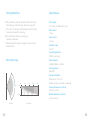
Functions
Press [setup]
button
Delete one of phone
numbers.
Delete all the phone numbers.
Default setting:
Disable
The default setting
is: High
If no number is
stored, the system
will not auto dial.
The system will exit
programming state after
two beeps.
18
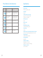
Phone Remote Control Instruction
Operation
19
Function
Illustration
Press
1
The system is armed after
one beep.
It’s recommended to arm the
system by phone if you forgot
to arm the system.
Press
0
The system is disarmed
after two beeps.
It’s recommended to disarm the
system by phone if you forgot
to take the remote control.
Press
9
Turn on siren
It can deter the intruders.
Press
6
Turn off siren
Press
Monitoring the site
Press
System exits phone remote
control state.
Hang up the phone
Specifications
Product name
PSTN Security alarm system
Model No.
CG-A8
Control panel’s power supply
Input: AC 110~240V/50~60Hz
Output: DC 12V/500mA
Standby current
25mA
Alarm current
260mA
Internal battery backup
7.4V/500mAh battery pack
Internal siren
100dB
Allowed amount of expandable wireless accessories
60 PCS in total (including Wireless Remote Control)
Radio frequency
315MHz/433MHz (±75KHz)
Housing material
ABS plastic
Operation condition
Temperature: -10°C~55°C
Humidity: ≤ 80% (non-condensing)
Panel size (L x W x H)
125×123×35mm
20
Disarm
Wireless Remote Control
LED Indicator
Arm
Stay
Disarm
Panic
Press {Disarm
} to disarm the alarm panel and the LED indicator
blacks out (siren hoots twice), the system is disarmed.
When intruders are detected, siren will keep hooting. If you press
{Disarm
} , siren will stop hooting but the corresponding zone
LED indicator on the panel still flashes for checking.
Arm
Press {Disarm
}again, all zone indicators black out.
Home Mode
Press {Arm
} to arm the alarm panel and the LED indicator
lights on (siren hoots once), the system enters Arm state.
If there comes an intruder, the siren will hoot to deter the intruder.
(The siren turns off after ringing for 5 minutes as default setting.)
At the same time, the system dials the pre-stored phone numbers
automatically.
21
Press {Stay
}, the arm state LED is on. The BCDE and 24-H zones
are armed except zone A. Accessories in zone A will not be activated.
You can move freely at home.
22
Mute Mode
Wireless Door/Window Contact
Features
Press {Stay
{Arm
} button on the remote control, then press
} or {Disarm
} button, the siren keeps silent to finish
The DWC- 100 is a Door/Window Contact that can be
installed on doors, windows, and any other objects that open
and close. The sensor transmits signals to the control panel
when a mag net mou nted near the sensor is mov ed away.
External input for wired accessor y is available at the N/C
interface. The tampe r protection ensures that sabotage
attempt s to mov e the contact will result in an alarm activation.
the operation. The system is armed or disarmed in mute without
disturbing other people.
Appearance
LED indicator
Emergency Call
Transmitter
Magnet
No matter what state the control panel is in, once SOS button on
the remote control is pressed, the system immediately goes into
emergent alarming state.
23
24
LED Indication
Installation & Notice
LED flashes once: Door/window is opened and
transmitter sends signal to the control panel.
LED flashes quickly when triggered: Low power indication,
please change battery as soon as possible.
Ope n the case and remov e the battery activation strip.
Mou nt the sensor on the door frame and the mag net on the door.
Mak e sure the mag net is on the right side of the transmitter
Place the transmitter in the desired location, mou nt the
mag net no more than 1cm away from the transmitter and secure
the transmitter and mag net with double-sided tapes or screws.
Avoid mou nting sensors in areas with a large quantity of met al
or electrical wiring, such as a furnace or utility room.
PCB Layout
AA 1.5V LR6
Tamper switch
Zone setting
Not e: Tamp er switch onl y wor ks in arm state
25
26
Wireless PIR Motion Detector
Specifications
Powe r supply
DC 1.5V (AA 1.5V LR6 Battery x 1pc)
Static current
≤ 30uA
Alarm current
≤ 40mA
Transmitting distance
≤80m (in open area)
Radio frequency
Features
PIR-900 is a high performan ce wireless P.I.R. mot ion detector.
It consists of digital dual-core fuzzy logic infrared control
chip and intelligent analysis which effectively identify
interference signals from body mov emen t signals and reduce
false alarm rate. With automa tic tempe rature comp ensation
and anti-air turbulence technology, it easily adapts to
environme ntal changes. The detector also has the advantages
of energy saving, reliability and easy installation.
315MHz /433MHz (±75KHz)
Housing mat erial
ABS plastic
Ope rating tempe rature
-10°C~55°C
Relative humidity
≤80% (non-condensing)
Transmitter dimen sions (LxWxH)
71 x 34 x 17.5mm
Mag net dimen sions (LxWxH)
51 x 12 x 13.5mm
27
28
Appearance
PCB Layout
LED ON / OFF
Infrared sensor
1. Detection window
2. LED indicator
3. Bracket
AA 1.5V LR6
AA 1.5V LR6
1
Tamper switch
2
3
LED Indication
Flash continuously: Under the self-testing state.
Flash once: Intruder is detected.
Flash twice: Self-testing is finished, enters the working mod e.
Flash once per 3 seconds: Under voltage indication, please
change the batteries immed iately.
29
Zone setting
Infrared sensor: It detects the infrared rays released by
human body motion, please don’t touch the surface and
always keep it clean.
Tamper switch: Once the case is opened in working state,
the tamper switch will be triggered and then generates
an alarm signal.
Usage
Ope n the case and remov e the battery activation strip to
activate batteries. It will start self-testing for one minute.
30
Mode Setting
Installation & Notices
Test Button
Avoid mou nting the detector close to windows, air conditioner,
heater, refrigerator, oven, su nshine and places where the
tempe rature changes fast or the air stream flows frequently.
If two detectors are installed in the same detection scope,
please adjust the location to avoid interference and false alarm.
2m
Testing mod e:
Af ter self-testing, press the test button, the sensor enters testing
mod e, and detects once every 10 seconds. Af ter 3 minutes, the
LED flashes twice, and the sensor enters the working mod e.
Working mod e:
In working state, if the sensor is triggered twice within 3 minutes,
it will enter sleeping mod e to save power. Af ter no mov emen t
within next 3 minutes, the sensor goes back to the working mod e.
Connect to alarm pan el:
Press the connect key on the alarm panel, and then press the
test button of the sensor twice to send alarm signal. Whe n one
beep is heard, they are connected.
To check if they are connected successfully, arm the system, and
trigger the sensor again, if there is an alarming, the connection
is successful.
31
Ground
Top view
Side view
Fix the bracket on the wall with screws and attach the detector to
the bracket. Adjust installation height or bracket to change the
detection distance and angle. It is recomme nded to mou nt it at
the height of 2m from the ground.
The detector is more sensitive to the cross mov emen t than to the
vertical mov emen t, so the performance of detector is best when the
detection direction is vertical to the walking direction of people.
32
Testing (Walk Test)
Specifications
Powe r supply
A. Af ter installation, power on the detector. Af ter one minute
self-testing, press the test button, walk in the scope (from
left to right or from right to left) and watch the LED indicator
to mak e sure the detector is working.
B. The LED indicator flashes once when body
mov emen t is detected.
C. Adjust the detector angle accordingly to achieve the best
detection effect.
DC 3V (AA 1.5V LR6 Battery x 2 pcs)
Static current
≤ 50uA
Alarm current
≤ 9.5mA
Detection scope
8m/110°
Transmitting distance
≤ 80m (in open area)
Detection Scope
Radio frequency
315MHz /433MHz (± 75KHz)
Housing mat erial
ABS plastic
Ope ration condition
Tempe rature: -10°C~55°C
0m
110°
2m
4m
2m
6m
8m
Relative humidity: ≤80% (non-condensing)
Detector dimen sions (L x W x H)
108 x 52 x 36.8 mm
Bracket dimen sions (L x W x H)
0m
52 x 30 x 26.5 mm
Top view
33
Side view
34