1
Using CPU Interrupts in the ServoPod-USB™
This applies to ServoPod-USB™ kernel v0.38 and later.
Interrupt Vectors in Flash ROM
The DSP56F807 processor used in the ServoPod-USB™ supports 64 interrupt vectors, in the first 128 locations of
Flash ROM. Each vector is a two-word machine instruction, normally a JMP instruction to the corresponding interrupt
routine. When an interrupt occurs, the CPU jumps directly to the appropriate address ($00-$7E) in the vector table.
Since this vector table is part of the ServoPod-USB™ kernel, it cannot be altered by the user. Also, some interrupts are
required for the proper functioning of the ServoPod-USB™, and these vectors must never be changed. So the
ServoPod-USB™ includes a “user” vector table at the high end of Flash ROM (addresses $7D80-7DFE). This is
exactly the same as the “kernel” vector table, except that certain “reserved for ServoPod-USB™” interrupts have been
excluded. The user vector table can be programmed, erased, and reprogrammed freely by the user, as long as suitable
precautions are taken.
Writing Interrupt Service Routines
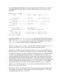
Interrupt service routines must be written in DSP56F80x machine language, and must end with an RTI (Return from
Interrupt) instruction. Some peripherals will have additional requirements; for example, many interrupt sources need to
be explicitly cleared by the interrupt service routine. For more information about interrupt service routines, refer to the
Motorola DSP56800 16-Bit Digital Signal Processor Family Manual (Chapter 7), and the Motorola
DSP56F801/803/805/807 16-Bit Digital Signal Processor User’s Manual.
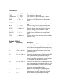
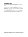
You should be aware that the ServoPod-USB™ uses certain channels in the Interrupt Priority controller:
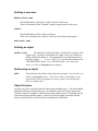
The IsoMax Timer (Timer D3) is assigned to Interrupt Priority Channel 3.
SCI#0 (RS-232) serial I/O is assigned to Interrupt Priority Channel 4.
The I/O Scheduling Timer7 is assigned to Interrupt Priority Channel 5.
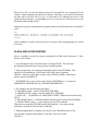
These channels may be shared by other peripherals. However, it is important to remember that these channels are
enabled by the IsoMax kernel after a reset, and must never be disabled. You should not use the corresponding bits in
the Interrupt Priority Register as interrupt enable/disable bits.
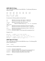
Interrupt channels 0, 1, 2, and 6 are reserved for your use. The IsoMax kernel does not use them, and you may assign,
enable, or disable them freely. Channel 0 has the lowest priority, and 6 the highest.8
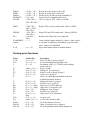
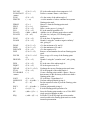
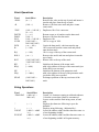
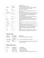
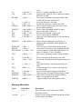
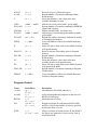
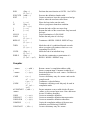
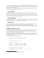
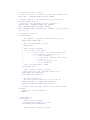
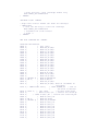
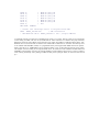
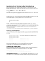
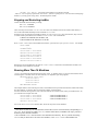
The User Interrupt Vector Table
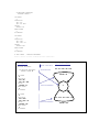
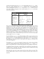
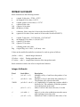
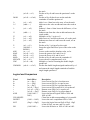
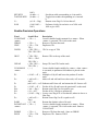
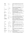
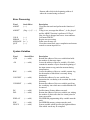
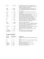
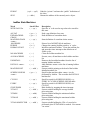
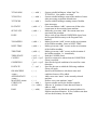
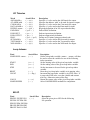
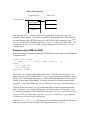
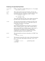
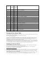
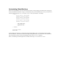
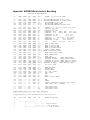
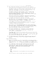
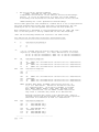
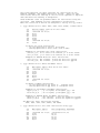
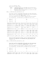
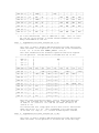
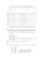
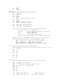
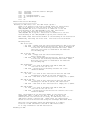
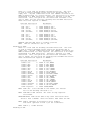
The user vector table is identical to the kernel (CPU) vector table, except that it starts at address $7D80 instead of
address $0. Each interrupt vector is two words in this table, sufficient for a machine language jump instruction. For all
interrupts which are not reserved by IsoMax, the kernel vector table simply jumps to the corresponding location in the
user vector table. (Remember that this adds the overhead of one absolute jump instruction -- 6 machine clock cycles -to the interrupt service.)
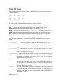
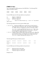
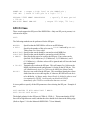
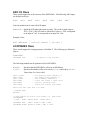
Note: ServoPod-USB™ kernels version 0.37 and earlier do not support a user vector table.
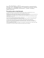
Note: This table is subject to change. Future versions of the ServoPod-USB™ software may reserve more of
these interrupts for internal use, as more I/O functions are added to the ServoPod-USB™ kernel.
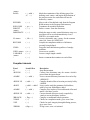
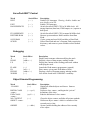
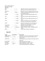
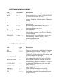
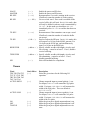
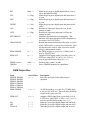
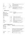
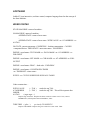
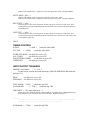
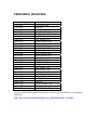
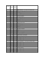
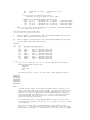
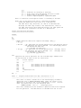
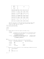
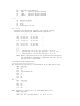
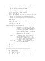
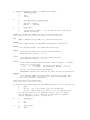
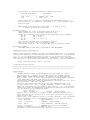
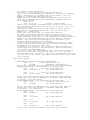
Interrupt
Number
0
1
2
7
User
Vector
Addres
s
$7D82
$7D84
Kernel Description
Vector
Addre
ss
$00
reset - reserved for ServoPod-USB™
$02
COP Watchdog reset
$04
reserved by Motorola
This will be a feature of future IsoMax kernels. Interrupt channel 5 is reserved for this use.
Use channel 6 only for critically-urgent interrupts, since it will take priority over channels 4 and 5, both of
which require prompt service.
8