1
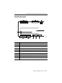
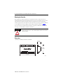
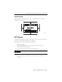
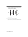
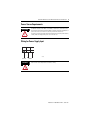
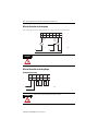
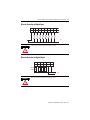
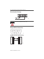
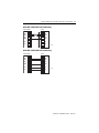
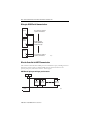
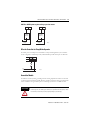
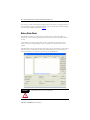
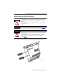
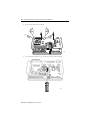
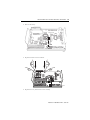
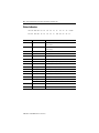
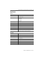
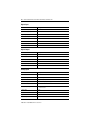
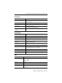
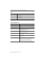
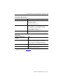
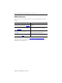
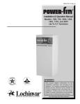
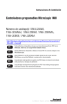
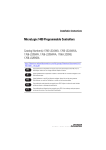
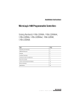
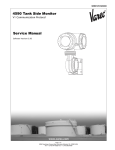
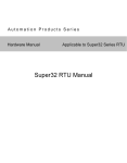
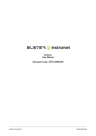
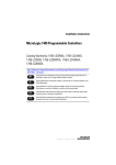
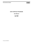
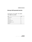
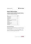
Installation Instructions
DataSite Natural Gas Flow Meter and Remote
Terminal Unit
Catalog Numbers 1758-FLO301, 1758-FLO302,
1758-RTU201, 1758-RTU202
Topic
Page
Important User Information
2
Environment and Enclosure
3
Hazardous Location Considerations
3
Overview
4
Controller Description
5
Mounting the Controller
6
DIN Rail Mounting
7
Power Source Requirements
9
Wiring for Power Supply Input
9
Wire the Controller for HART Communication
14
Ground the Module
15
Status Indicators
20
Specifications
21
Additional Resources
26
2
DataSite Natural Gas Flow Meter and Remote Terminal Unit
Important User Information
Solid state equipment has operational characteristics differing from those of electromechanical equipment.
Safety Guidelines for the Application, Installation and Maintenance of Solid State Controls (Publication
SGI-1.1 available from your local Rockwell Automation sales office or online at
http://literature.rockwellautomation.com) describes some important differences between solid state
equipment and hard-wired electromechanical devices. Because of this difference, and also because of the
wide variety of uses for solid state equipment, all persons responsible for applying this equipment must
satisfy themselves that each intended application of this equipment is acceptable.
In no event will Rockwell Automation, Inc. be responsible or liable for indirect or consequential damages
resulting from the use or application of this equipment.
The examples and diagrams in this manual are included solely for illustrative purposes. Because of the many
variables and requirements associated with any particular installation, Rockwell Automation, Inc. cannot
assume responsibility or liability for actual use based on the examples and diagrams.
No patent liability is assumed by Rockwell Automation, Inc. with respect to use of information, circuits,
equipment, or software described in this manual.
Reproduction of the contents of this manual, in whole or in part, without written permission of Rockwell
Automation, Inc., is prohibited.
Throughout this manual, when necessary, we use notes to make you aware of safety considerations.
WARNING
IMPORTANT
ATTENTION
Identifies information about practices or circumstances that can cause an explosion in
a hazardous environment, which may lead to personal injury or death, property
damage, or economic loss.
Identifies information that is critical for successful application and understanding of
the product.
Identifies information about practices or circumstances that can lead to personal injury
or death, property damage, or economic loss. Attentions help you identify a hazard,
avoid a hazard and recognize the consequences.
SHOCK HAZARD
Labels may be on or inside the equipment (for example, drive or motor) to alert people
that dangerous voltage may be present.
BURN HAZARD
Labels may be on or inside the equipment (for example, drive or motor) to alert people
that surfaces may reach dangerous temperatures.
Publication 1758-IN001C-EN-P - June 2011
DataSite Natural Gas Flow Meter and Remote Terminal Unit
3
Environment and Enclosure
ATTENTION
Do not remove the protective debris strip until after the module and all other equipment
in the panel near the module are mounted and wiring is complete. Once wiring is
complete, remove protective debris strip. Failure to remove strip before operating can
cause overheating.
ATTENTION
Electrostatic discharge can damage semiconductor devices inside the module. Do not
touch the connector pins or other sensitive areas.
ATTENTION
To comply with UL restrictions, the product and any connected devices must be powered
from a source compliant with the following:
Class 2 or Limited Voltage/Current.
Hazardous Location Considerations
This equipment is suitable for use in Class I, Division 2, Groups A, B, C, D locations only.
The following WARNING statement applies to use in hazardous locations.
WARNING
EXPLOSION HAZARD
• Substitution of components may impair suitability for Class I, Division 2.
• Do not replace components or disconnect equipment unless power has been
switched off.
• Do not connect or disconnect components unless power has been switched off.
• This product must be installed in an enclosure. All cables connected to the product
must remain in the enclosure or be protected by conduit or other means.
• All wiring must comply with N.E.C. article 501-10(b).
Use only the following communication cables in Class I, Division 2 hazardous locations.
Environment Classification
Communication Cables
Class I, Division 2 Hazardous Environment
1747-CP3 RS-232 Serial Communications Cable
Publication 1758-IN001C-EN-P - June 2011
4
DataSite Natural Gas Flow Meter and Remote Terminal Unit
Environnements dangereux
Cet équipement est conçu pour une utilisation en environnements dangereux de Classe I,
Division 2, Groupes A, B, C, D. La mise en garde suivante s’applique à utilisation en
environnements dangereux.
WARNING
DANGER D’EXPLOSION
• La substitution de composants peut rendre cet équipement impropre à une
utilisation en environnement de Classe I, Division 2.
• Ne pas remplacer de composants ou déconnecter l’équipement sans s’être assuré
que l’alimentation est coupée.
• Ne pas connecter ou déconnecter des composants sans s’être assuré que
l’alimentation est coupée.
• Ce produit doit être installé dans une armoire. Tous les câbles connectés à
l’appareil doivent rester dans l’armoire ou être protégés par une goulotte ou tout
autre moyen.
• L’ensemble du câblage doit être conforme à la réglementation en vigueur dans les
pays où l’appareil est installé.
Utilisez uniquement les câbles de communication suivants dans les environnements
dangereux de Classe I, Division 2.
Classification des environnements
Câbles de communication
Environnement dangereux de Classe I, Division 2
1747-CP3 RS-232 Serial Communications Cable
Overview
DataSite controllers are suitable for use in an industrial environment when installed in
accordance with these instructions. Specifically, this equipment is intended for use in clean,
dry environments (Pollution degree 2(1)) and with circuits not exceeding Over Voltage
Category II(2) (IEC 60664-1).(3)
Install your DataSite unit using these installation instructions.
(1)
Pollution Degree 2 is an environment where, normally, only non-conductive pollution occurs except that occasionally a
temporary conductivity caused by condensation shall be expected.
(2)
Over Voltage Category II is the load level section of the electrical distribution system. At this level transient voltages are
controlled and do not exceed the impulse voltage capability of the product’s insulation.
(3)
Pollution Degree 2 and Over Voltage Category II are International Electrotechnical Commission (IEC) designations.
Publication 1758-IN001C-EN-P - June 2011
DataSite Natural Gas Flow Meter and Remote Terminal Unit
5
Controller Description
1
DICOM DI0 DI1 DI2 DI3 DI4 DI5 DI6 DI7
2
3
+ _
WAKEUP
ON
9
10
0
1
2
H0+ H0- H1+ H1- H2+ H2- P10 P11 P12 PI AOV+ AOV- AO0 AOV- AO1 AOVCOM
Data
V+ V- AI0 AI1 AI2 AI3 AI4 AI5 V-
DO0 DO1 DO2 DO3 VDO+ VDO-
+
_
44376
44379
8
7
Item
Description
1
Discrete Inputs and wake up connectors
2
Status indicators
3
Ethernet connector
4
RS 232 COM 2 connector
5
RS 232 COM 1 connector
6
RS 485 COM 1 connector
7
Discrete Output connectors
8
Power Input and Analog Input connectors
6
5
9
HART, Pulse Input, and Analog Output connectors
10
Pulse Input Filter switches
4
Publication 1758-IN001C-EN-P - June 2011
6
DataSite Natural Gas Flow Meter and Remote Terminal Unit
Mounting the Controller
Most applications require installation in an industrial enclosure to reduce the effects of
electrical interference and environmental exposure. Locate your controller as far as possible
from power lines, load lines, and other sources of electrical noise such as hard-contact
switches, relays, and AC motor drives. For more information on proper grounding guidelines,
see the Industrial Automation Wiring and Grounding Guidelines, publication 1770-4.1.
You can mount the controller either horizontally or vertically on DIN rails, but horizontal
mounting is recommended for thermal considerations.
ATTENTION
Be careful of metal chips when drilling mounting holes for your controller or other
equipment within the enclosure or panel. Drilled fragments that fall into the controller
could cause damage.
Dimensions
1758-FLO301, 1758-FLO302, 1758-RTU201, 1758-RTU202
5.6 cm
(2.20 in.)
13.0 cm
(5.12 in.)
21.3 cm
(8.395 in.)
Publication 1758-IN001C-EN-P - June 2011
44374
DataSite Natural Gas Flow Meter and Remote Terminal Unit
7
Controller Spacing
When mounting the controller, allow 25 mm (1 in.) of space on all sides for adequate
ventilation, as shown below.
Top
Side
Side
Bottom
44375
DIN Rail Mounting
A small Phillips screwdriver is required for the installation or removal of the controller. The
controller can be mounted to EN50022-35 x 7.5 DIN rails.
Follow these steps to install your controller on the DIN rail.
1. Mount your DIN rail.
Make sure that the placement of the controller on the DIN rail meets the
recommended spacing requirements.
2. Loosen the two clamp screws until the clamp can slide out.
IMPORTANT
D
Do not remove the screws from the clamp, otherwise they will fall into the
chassis.
3. Place the controller onto the DIN rail, using the rail hooks on the back of the
controller.
Publication 1758-IN001C-EN-P - June 2011
8
DataSite Natural Gas Flow Meter and Remote Terminal Unit
4. Slide the clamp out while pushing the controller fully onto the DIN rail (1). When the
controller is properly aligned on the DIN rail (2), slide the clamp in, so that it makes
direct contact with the lower edge of the DIN rail (3).
1
2
3
DIN rail
44538
44539
44540
5. Tighten the clamp screws.
Follow these steps to remove your controller from the DIN rail.
1. Loosen the two clamp screws until the clamp can slide out, taking care not to dislodge
the clamp screws from the clamp.
2. Remove the controller.
Publication 1758-IN001C-EN-P - June 2011
DataSite Natural Gas Flow Meter and Remote Terminal Unit
9
Power Source Requirements
The DataSite modules (1758-FLO301, 1758-FLO302, 1758-RTU201, 1758-RTU202) must
be powered by a National Electrical Code (NEC) or Canadian Electrical Code (CEC) Class 2
power source when used in locations covered by Underwriters Laboratories.
In locations governed by International Electrotechnical Commission (IEC) or EN standards,
a Safety Extra Low Voltage (SELV) power source must be used.
ATTENTION
Wiring for Power Supply Input
1
2
3
V+
V-
44380
Ground
WARNING
12V DC
Refer to Power Source Requirements for details on wiring.
Publication 1758-IN001C-EN-P - June 2011
10
DataSite Natural Gas Flow Meter and Remote Terminal Unit
Wire the Controller for Analog Input
The analog input circuits are equipped with overvoltage and overcurrent protection.
4
5
6
7
8
9
AI0 AI1 AI2 AI3 AI4 AI5
Two wire
sensor
10
V-
Three
wire
sensor
44381
24VDC
WARNING
Power Supply
Refer to Power Source Requirements for details on wiring.
Wire the Controller for Analog Output
Analog Output wiring
40
41
42
43
44
45
AOV+ AOV- AO0 AOV- AO1 AOVLOAD
LOAD
44382
12~24V
WARNING
Refer to Power Source Requirements for details on wiring.
Publication 1758-IN001C-EN-P - June 2011
DataSite Natural Gas Flow Meter and Remote Terminal Unit
11
Wire the Controller for Digital Input
19
20
21
22
23
24
25
26
27
DICOM DI0
DI1
DI2
DI3
DI4
DI5
DI6
DI7
28
44383
12~24V DC
WARNING
Refer to Power Source Requirements for details on wiring.
Wire the Controller for Digital Output
13
14
D00
D01
D02
D03 D0V+ D0V-
LOAD
LOAD
15
16
LOAD
12
LOAD
24V FET
OUTPUT
11
12~24V
WARNING
44384
Refer to Power Source Requirements for details on wiring.
Publication 1758-IN001C-EN-P - June 2011
12
DataSite Natural Gas Flow Meter and Remote Terminal Unit
Wire the Controller for Pulse Input
35
36
37
38
39
PI0
PI1
PI2
PI-
40
44385
12~24V
Refer to Power Source Requirements for details on wiring.
WARNING
Wiring for RS232 Serial Communications
5
GND
4
9
3
TxD
8
CTS
7
RTS
1
2
RxD
6
44377
RS232 DTE to RS232 DTE without Handshaking
RS232 (DTE)
DCD 1
RXD 2
TXD 3
DTR 4
GND 5
6
RTS 7
CTS 8
9
DTE
1
2
3
4
5
6
7
8
9
DCD
RXD
TXD
DTR
GND
RTS
CTS
Publication 1758-IN001C-EN-P - June 2011
44387
DataSite Natural Gas Flow Meter and Remote Terminal Unit
13
RS232 DTE to RS232 DTE with Handshaking
RS232 (DTE)
DCD 1
RXD 2
TXD 3
DTR 4
GND 5
6
RTS 7
CTS 8
9
DTE
1
2
3
4
5
6
7
8
9
DCD
RXD
TXD
DTR
GND
RTS
CTS
44388
RS232 DTE to RS232 DCE with Handshaking
RS232 (DTE)
DCE
DCD
RXD
TXD
DTR
GND
1
2
3
4
5
6
7
8
9
RTS
CTS
1
2
3
4
5
6
7
8
DCD
RXD
TXD
DTR
GND
RTS
CTS
44389
Publication 1758-IN001C-EN-P - June 2011
14
DataSite Natural Gas Flow Meter and Remote Terminal Unit
Wiring for RS485 Serial Communications
Master
Station
First station in network
requires terminations
D
D
Slave
Station
D
D
RS-485 network
1200 m (4000 feet)
maximum length
Slave
Station
D
D
Last station in network
requires terminations
44390
Wire the Controller for HART Communication
The controller comes with three HART protocol communications ports, including one that is
multi-point, and can connect to thirteen HART protocol meters. The other two are
point-to-point ports, and can also collect 4…20 mA signals.
HART0 multi-point port wiring to passive meters
HO+ HO-
Two Wire
Slave #1
Two Wire
Slave #2
DC Power
Supply
Publication 1758-IN001C-EN-P - June 2011
Two Wire
Slave #13
44391
DataSite Natural Gas Flow Meter and Remote Terminal Unit
15
HART1 or HART2 point-to-point wiring to passive meters
H1+ H1-
H2+
Two Wire
Slave #1
H2-
Two Wire
Slave #2
DC Power
Supply
DC Power
Supply
44393
Wire the Controller for Sleep/Wake Up mode
To reduce power consumption in unattended or solar-powered applications, the controller
can be configured to enable Sleep mode, and disable Sleep mode when inputs are detected.
27
28
29
WAKEUP
+
-
44396
12~24V DC
Ground the Module
In solid-state control systems, grounding and wire routing help limit the effects of noise due
to electromagnetic interference (EMI). Run the ground connection from the ground terminal
of the controller to the ground bus prior to connecting any devices. Use AWG #14 wire.
ATTENTION
All devices connected to the RS-232/485 communication port must be referenced to
controller ground, or be floating (not referenced to a potential other than ground). Failure
to follow this procedure may result in property damage or personal injury.
Publication 1758-IN001C-EN-P - June 2011
16
DataSite Natural Gas Flow Meter and Remote Terminal Unit
You must also provide an acceptable grounding path for each device in your application. For
more information on proper grounding guidelines, refer to the Industrial Automation Wiring
and Grounding Guidelines, publication 1770-4.1.
Battery Status Check
The DataSite controller uses a lithium battery that allows the real-time-clock (RTC) to
maintain the correct time setting through periods when line power has been removed from
the unit.
Current drain on the battery during these periods is approximately 1 microamp, and the
battery should provide approximately 10 years of operation for the RTC without power
applied.
The DS Settings Utility provides a display of the battery voltage. If the battery voltage should
drop below 2.0 V, contact Rockwell Automation Technical Support (see the back page for
contact information) to arrange for repair/exchange of the DataSite unit.
WARNING
The lithium battery is not user replaceable.
Publication 1758-IN001C-EN-P - June 2011
DataSite Natural Gas Flow Meter and Remote Terminal Unit
17
Decommission and Recycle the Battery
WARNING
IMPORTANT
WARNING
The lithium battery is not user replaceable. Follow the instructions in this section to
remove the battery from the DataSite unit for recycling when decommissioning the
DataSite unit.
Dispose of used battery promptly. Keep away from children. Do not disassemble and do
not dispose of in fire.
Refer to the SLC 500 Lithium Battery Installation Instructions, publication 1747-IN515, for
more information on handling, usage, storage, and disposal of lithium batteries.
When you connect or disconnect the battery an electrical arc can occur. This could cause
an explosion in hazardous location installations. Be sure that the area is nonhazardous
before proceeding.
For Safety information on the handling of lithium batteries, including handling and
disposal of leaking batteries, see Guidelines for Handling Lithium Batteries,
publication AG 5-4.
1. Remove the cover by first removing the screws on either side of the controller.
44737
Publication 1758-IN001C-EN-P - June 2011
18
DataSite Natural Gas Flow Meter and Remote Terminal Unit
2. Pry the board off from the standoffs.
44738
3. Use a flat-blade screwdriver to pry the battery out from under the clamp.
CR2325
LITHIUM BATTERY
44739
Publication 1758-IN001C-EN-P - June 2011
DataSite Natural Gas Flow Meter and Remote Terminal Unit
19
4. Remove the battery.
CR2325
LITHIUM BATTERY
44740
5. Replace the board onto the standoffs.
44741
6. Replace the cover, and fasten the screws securely.
Publication 1758-IN001C-EN-P - June 2011
20
DataSite Natural Gas Flow Meter and Remote Terminal Unit
Status Indicators
PWR STAT DO0 DO2
RUN ERR
DI0
DI2
DI4
DI6
PI0
PI2
TX0 TX1
DO1 DO3 DI1
DI3
DI5
DI7
PI1
LINK RX0 RX1
TX2 10\100M
RX2 F\H
Indicator
State
Description
PWR
Green
Power is applied. This indicator is not affected by LED power
control settings.
RUN
Green
Normal operation. This indicator is not affected by LED power
control settings.
STAT
Flashing red
ISaGRAF application running
ERR
Yellow
Error detected
DI0…DI7
Green
Corresponding digital input is on
DO0…DO3
Green
Corresponding digital output is on
PI0…PI2
Green
Corresponding pulse input voltage is more than 8V
TX0
Flashing red
Transmitting data through HART port
RX0
Flashing green
Receiving data through HART port
TX1
Flashing red
Transmitting data through serial port 1
RX1
Flashing green
Receiving data through serial port 1
TX2
Flashing red
Transmitting data through serial port 2
RX2
Flashing green
Receiving data through serial port 2
LINK
Flashing yellow
Transmitting or receiving data through Ethernet port
Yellow
Controller is connected to Ethernet network
10\100M
Red
Speed for ethernet connection, 10\100 Mbps
F\H
Green
Ethernet mode, half duplex or full duplex
Publication 1758-IN001C-EN-P - June 2011
DataSite Natural Gas Flow Meter and Remote Terminal Unit
21
Specifications
General
Attribute
Description
Dimensions
213 x 133 x 56 mm
(8.375 x 5.25 x 2.20 in.)
Number of I/O
8 digital inputs
4 digital outputs
8 analog inputs
2 analog outputs
3 pulse inputs
Power supply voltage
12V DC, (-15%, +10%)
Heat dissipation, nominal
< 1.2 W
Power consumption
80…120 mA
Input circuit type
Current Sinking
Output circuit type
Current Sourcing (FET)
Terminal screw torque
0.8 Nm (7 in-lb)
North American temp code
T4
Wire size
0.34... 2.5 mm² (22...12 AWG) solid or stranded copper wire rated at
90 °C (194 °F ) or greater 1.2 mm (3/64 in.) insulation max
Pulse Input
Attribute
Description
Voltage range
12…24V DC
Off-state voltage
8V DC
Operating frequency
10 kHz with filters off
30 kHz with filters on
On-state current, min
5 mA
On-state current, nom
6 mA
On-state current, max
13.2 mA
Off-state leakage current
2.5 mA
Nominal impedance
2 kΩ
Publication 1758-IN001C-EN-P - June 2011
22
DataSite Natural Gas Flow Meter and Remote Terminal Unit
Digital Input
Attribute
Description
On-state voltage range
8…24V DC
Off-state voltage range
0…4V DC
Operating frequency
100 Hz
On-state current, min
3 mA
On-state current, nom
5 mA
On-state current, max
11 mA
Off-state leakage current
2 mA
Nominal impedance
2.4 kΩ
Digital Output
Attribute
Description
Power supply
12…24V DC
Continuous current per point
200 mA
Operating frequency
100 Hz
On-state current, min
1 mA
On-state current, max
200 mA
Off-state leakage current
1 mA
Analog Inputs
Attribute
Description
A/D resolution
16-bit
Conversion type
Successive approximation
Type
Single ended (unipolar)
Isolation voltage
500V AC from logic power supply
Transient variety protection
600 W
Voltage Input Range
0…10V DC or
4…20 mA versions
Upload time
10 ms
Response time
10 ms (10…90%)
Type of Data
Integer
Input Coding
Hexadecimal
Publication 1758-IN001C-EN-P - June 2011
DataSite Natural Gas Flow Meter and Remote Terminal Unit
23
Analog Inputs
Attribute
Description
Voltage input impedance
100 kΩ for 10V DC inputs
170 Ω for 20 mA inputs
Input Resolution
16-bit
Non-linearity
±0.1% of full scale
Overall accuracy
±0.1% of full scale at 25 °C
±0.3% of full scale over temperature range
Voltage Input Overvoltage
Protection
Continuous input must not exceed 160% of the rated range
Analog Outputs
Attribute
Description
D/A resolution ratio
16-bit
Power supply
Successive approximation
Output signal range
4…20 mA
Maximum load
Impedance
1000 Ω with 24V DC loop power
400 Ω with 12V DC loop power
Output type
Single ended regulation on positive side with common negative return
Isolation voltage
70V AC or 100V DC
Absolute accuracy
±0.2% (25 °C with 250 Ω load)
±0.5% (full temperature range, 0…1000 Ω load)
Response time
100 ms typical (10…90%)
Noise and ripple, max
0.04%
Transient protection
600 W
HART
Attribute
Description
Modulation
Frequency Shift Keying (FSK)
Logic 1 - 1200 Hz
Logic 0 - 2200 Hz
Data rate
1200 bps
Transmit level
500 mVp-p / 250 Ω
Receive sensitivity
120 mVp-p/ on
80 mVp-p/ off
Publication 1758-IN001C-EN-P - June 2011
24
DataSite Natural Gas Flow Meter and Remote Terminal Unit
HART
Attribute
Description
Output impedance
300 Ω
transformer isolated
Input impedance
4000 Ω
transformer isolated
Load resistor
250 Ω, 1 W max
Environmental Specifications
Attribute
Value
Temperature, operating
-40... 70 °C (-40 ...158 °F)
Temperature, non-operating
-50...80 °C (-58... 176 °F)
Relative humidity
5...95% non-condensing
Vibration
IEC 60068-2-6
Constant amplitude 0.15mm: 10…57 Hz
Constant acceleration 2g: 57…150 Hz
Shock
IEC 60068-2-27
18 shocks, semi-sinusoidal 15g / 11 ms
Electrical/EMC
EN 61000-6-4 2007;
EN 61000-6-2 2005
ESD immunity
IEC 61000-4-2:
4 kV contact discharges
8 kV air discharges
Radiated RF immunity
IEC 61000-4-3:
10V/m with 1 kHz sine-wave 80% AM from 80…1000 MHz
10V/m with 200 Hz 50% Pulse 100% AM at 900 MHz
10V/m with 200 Hz 50% Pulse 100% AM at 1890 MHz
3V/m with 1 kHz sine-wave 80% AM from 1000…2700 MHz
Publication 1758-IN001C-EN-P - June 2011
DataSite Natural Gas Flow Meter and Remote Terminal Unit
25
Environmental Specifications
Attribute
Value
EFT/B immunity
IEC 61000-4-4:
±2 kV at 5 kHz on power ports
±2 kV at 5 kHz on signal ports
±1 kV at 5 kHz on communications ports
Surge transient immunity
IEC 61000-4-5:
±1 kV line-line(DM) and ±2 kV line-earth(CM) on power ports
±1 kV line-line(DM) and ±2 kV line-earth(CM) on signal ports
±1 kV line-earth(CM) on shielded ports
±1 kV line-earth(CM) on communications ports
Conducted RF immunity
IEC 61000-4-6:
10V rms with 1 kHz sine-wave 80% AM from 150 kHz…80 MHz
Certifications
Certification (when product is
Value
marked)(1)
C-UL-US
UL Listed Industrial Control Equipment
UL Listed Industrial Control Equipment for use in Canada
UL Listed for Class I, Division 2 Group A,B,C,D Hazardous
Locations, certified for U.S. and Canada. See UL File E10314
CE
Marked for all application directives
C-Tick
Australian Radiocommunications Act, compliant with:
AS/NZS CISPR 11; Industrial Emissions
(1)
See the Product Certification link at http://www.ab.com for Declaration of Conformity, Certificates, and other certification
details.
Publication 1758-IN001C-EN-P - June 2011
26
DataSite Natural Gas Flow Meter and Remote Terminal Unit
Additional Resources
These documents contain additional information concerning related Rockwell Automation
products.
Resource
Description
DataSite Electronic Flow Meter and Remote
Terminal Unit Hardware User Manual 1758-UM001
Information on how to install and wire a DataSite
controller.
Customized Function Blocks for DataSite Electronic
Flow Meter and Remote Terminal Unit User
Manual 1758-RM001
Description of the customized function blocks used for
programming DataSite controllers using ISaGRAF
software.
DataSite Electronic Flow Meter and Remote
Terminal Unit Software User Manual
1758-UM002
Information on how to install and use the software
tools, DS Settings, DS FloConfig, and DS DNP3 to
configure and monitor DataSite controllers.
Industrial Automation Wiring and Grounding
Guidelines, publication 1770-4.1
Provides general guidelines for installing a Rockwell
Automation industrial system.
You can view or download publications at http://literature.rockwellautomation.com. To
order paper copies of technical documentation, contact your local Rockwell Automation
distributor or sales representative.
Publication 1758-IN001C-EN-P - June 2011
DataSite Natural Gas Flow Meter and Remote Terminal Unit
27
Notes:
Publication 1758-IN001C-EN-P - June 2011
Rockwell Automation Support
Rockwell Automation provides technical information on the Web to assist you in using its
products. At http://support.rockwellautomation.com, you can find technical manuals, a
knowledge base of FAQs, technical and application notes, sample code and links to software
service packs, and a MySupport feature that you can customize to make the best use of these
tools.
For an additional level of technical phone support for installation, configuration and
troubleshooting, we offer TechConnect support programs. For more information, contact
your local distributor or Rockwell Automation representative, or visit
http://support.rockwellautomation.com.
Installation Assistance
If you experience a problem within the first 24 hours of installation, please review the
information that's contained in this manual. You can also contact a special Customer Support
number for initial help in getting your product up and running.
United States
1.440.646.3434
Monday – Friday, 8 a.m. – 5 p.m. EST
Outside United States
Please contact your local Rockwell Automation representative for any technical
support issues.
New Product Satisfaction Return
Rockwell Automation tests all of its products to ensure that they are fully operational when
shipped from the manufacturing facility. However, if your product is not functioning and
needs to be returned, follow these procedures.
United States
Contact your distributor. You must provide a Customer Support case number (call the
phone number above to obtain one) to your distributor in order to complete the return
process.
Outside United States
Please contact your local Rockwell Automation representative for the return
procedure.
Allen-Bradley, Rockwell Automation, DataSite, and TechConnect are trademarks of Rockwell Automation, Inc.
Trademarks not belonging to Rockwell Automation are property of their respective companies.
Publication 1758-IN001C-EN-P - June 2011
Supercedes Publication 1758-IN001B-EN-P November 2010
PN-117506
Copyright © 2011 Rockwell Automation, Inc. All rights reserved. Printed in China.