1
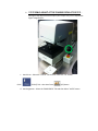
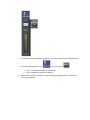
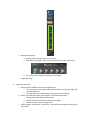
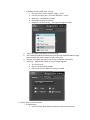
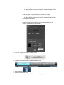
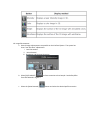
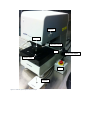
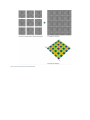
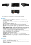
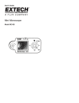
Olympus LEXT OLS 4000 Confocal Laser Microscope
The Olympus LEXT OLS4000 is a confocal microscope capable of taking high-resolution 3D images. The
magnification (Optical and Digital) of this microscope ranges from 108x – 17,280x. It is capable of
resolving features 10 nm in size in the z direction (sample height) and 120 nm in the x-y plane. The
system is capable of performing a variety of metrology measurements. Step height, surface/line
roughness, and area/volume measurements are some of the more commonly used metrology
measurements. Figure 1 at the end of the text contains an image with key hardware identified on it.
1. Purpose
This manual describes best known methods for capturing 3D images and describes some of the more
commonly used measurement capabilities of the system. Users must be trained on the operation of the
microscope in order to use it. Only qualified users who have been trained may use the system. There
are several pinch points that users must be aware of prior to use.
2. Reference Material
a. http://www.olympus-ims.com/en/metrology/ols4000/
b. LEXT User Manual Wizard - contact lab staff for full electronic copy
3. Safety Instructions
a. EMO button can be depressed at any time to stop power to the system
b. Do Not insert or remove a sample while the laser is on – MUST BE IN [COLOR] MODE
c. Liquids/wet samples are not permitted on the system at anytime
d. Keep hands from of the system – there are several pinch points that can occur due to
moving objective lenses and stages.
e. The system is equipped with a Class III laser
i. Users should be familiar with OSHA mandates for this class of laser products:
https://www.osha.gov/dts/osta/otm/otm_iii/otm_iii_6.html
ii. Maintenance should only be performed by an authorized service representative.
4. System Specifications:
Objective Lens Magnification: 5x to 100x
Laser 3D image Magnifications: 20X to 100X
Digital Magnification: 1 to 8x
Total Magnification capability: 5x to 17,280x
Color Imaging Mode: White LED Light, 2-megapixel CCD Detector
Laser Imaging Mode: 405 nm Laser, Photomultiplier Detector
Minimum Z-Resolution: 10 nm
Minimum XY-Resolution: 120 nm
5. Logging in
a. Login to the computer with User: LEXT Password: Olympus
b. Startup: Double click the OLS4000 icon on the Windows desktop
c. Click on “Allow, I trust this program”
d. Login with User ID: ADMIN Password: olympus
e. Clear off the stage – System will ask the user to check the safety around a sample,
object lens, and the stage.
f. The system will then ask if the user would like to “move the reference Z position” Select
[OK] provided nothing is on the stage.
6. Objectives Information
Lens
Magnification
(optical – 8x digital)
5x
10x
20x
50x
50x
100x
Field of view (um)
Working Distance
(mm)
Numerical
Aperture
2560 - 320
1280 -160
640 - 80
640 - 80
256 - 32
128 - 16
20.0
11.0
1.0
10.6
0.35
0.35
0.15
0.30
0.60
0.50
0.95
0.95
108x - 864x
216x - 1728x
432x - 3456x
1080x – 8640x
1080x - 8640x
2160x - 17280x
7. Loading and Unloading of Samples
a. LOAD AND UNLOAD at 5x!
i. Loading at higher magnifications can cause damage the objective lenses
ii. Loading at higher magnifications can damage your samples.
iii. To load – press the “move to load/unload” button
iv. Then Press the “move to origin”
v. To Unload – Press the load/unload – remove sample – return stage to home
position – These may be located on the [MAP SCREEN] tab
b. Do not place your fingers by the objective lenses – Potential pinch point.
c. Never move the stage or the objective lenses by hand. The system has software
features that will move the stage/objective lenses.
d. Adjust Coarse Focus (discussed in next section) if sample is large to ensure it does not
make contact with the objective lenses.
e. At any point in time, an image reference for an area of interest can be set using the
f.
[update snapshot]
icon to the right of the Map Screen tab
The green box will show the last known area of interest defined by the user
8. Imaging:
a. Select “Imaging” then “Microscope” then “Color” or “Laser”
then
COLOR
then either
or, LASER
b. Coarse Focus – Generally not needed
i. Upon placing the sample on the stage – adjust the coarse focus
ii. Never force the coarse focus adjustment – make sure the coarse focus is
unlocked – the locking collar is on the right side at the back of the unit. See
Picture.
iii.
!!!!!!!!!ONLY ADJUST AT THE COARSE FOCUS AT 5X!!!!!!! –
Damage to the objective lenses and/or your sample may occur if adjusted at
higher magnification.
c. Auto Focus – Select the “FOCUS” Tab and then select the “AF” button
CLICK
[FOCUS] Tab – then Auto Focus
[AF] Button
d. Auto Brightness – Select the “BRIGHTNESS” Tab and then Select “AUTO” button
e. To manually adjust the brightness up/down – user must unlock the Auto Brightness first
f.
To enable auto brightness - Click
Tab – then [AUTO]
i. Color – No Automatic Brightness adjustment
ii. Laser – Brightness Automatically Adjusts
g. Manual Focus can be achieved by moving the objective stage up/down to achieve the
correct focal distance.
h. Magnification Change
i. Simply select the magnification on the screen.
ii. KEEP Hands and Fingers away from objectives while moving – Pinch Point
i.
iii. Auto Focus should engage and display the live image.
Image Capturing:
9. Acquiring a 3D Image
a. Always uses the LASER to capture an image (405 nm)
i. The instrument is only rated to take measurements on the 20x, 50x (high NA),
and 100x objectives.
ii. An image taken at 5x and 10x may not give you accurate readings
b. Move to the desired location on the sample – Can be done three ways:
i. Moving the sample stage with the Joystick
ii. Double Clicking on the small sample captured image
iii. Double Clicking on the live image screen
c. Under Imaging – Microscope – Color/Laser – select the desired acquisition settings for
the sample.
i. Dropdown contains: FINE, FAST, or STEP
1. Fine uses a finer pitch to capture images – 10 um
2. Fast uses a coarser pitch – less scans and faster – 20 um
3. Multi-layer – See Manual for details
4. STEP allows users to set the pitch
5. Snap Shot – No Pitch change – just captures image on screen
ii. “Color” will capture and display a 3D color image
iii. “DIC” stands for Differential Interference Contrast and maybe desired for image
enhancements with the use polarizers and a color prism
iv. “Manual” will require the users to set the Top and Bottom Focal Planes
v. “Stitching” – Maybe used to quilt an array of images together
1. 25 x 25 max array
2. Figure 2 shows stitched example
3. Contact Lab staff for additional training if needed
d. Select “Step” to setup manually
i. Set the bottom
1. Scroll the mouse down past the lowest focal plane on the sample
a. If Red appears – turn down the brightness using “AB”
b. Red indicates oversaturated signal on the Photomultiplier Tube
2. Set the “TOP” button
ii. Set the top
1. Scroll the mouse up past the top focal plane on the sample
a. If Red appears – turn down the brightness using “AB”
b. Red indicates oversaturated signal on the Photomultiplier Tube
2. Set the “BOTTOM” button
iii. Set the pitch (10 nm or 0.010 um min)
1. Number of Steps (Focal Plane Cuts) will be displayed based on the
distance between the top and bottom
e. Press the “Acquisition” button to obtain image
f.
Image will now appear under the [MEASUREMENTS] tab
g. Select [PROFILE]
h. Select one of the four views
i. Color only appears if [COLOR] was selected during acquisition.
10. Image Enhancement
a. Several Image enhancements are possible on the Confocal System. The system has
three “one-shot filter” adjustments.
i. Level Corrections
ii. Noise Removal
iii. Brightness and Contrast Correction
b. Select [LEVEL ADJUST]
from LEXT Manual in Figure 3.
c. Select the [Noise Removal]
surface correction to level sample. See before/after
button and select the desired profile correction
d. Brightness and Contrast Image Enhancement
e. The image can be returned to its original state at anytime by selecting the [UNDO]
button
f.
Manual correction of the images can be obtained by using the
CORRECTION] button
[IMAGE
11. DIC Image Capture
a. From Manual: “Creates a shadowing effect on color and laser images, creating 3D
topologically-inaccurate images with features that “pop-out.” (See Figure 4) Works by
splitting polarized light into two rays that provide information about adjacent points on
a sample. Rays are recombined to determine differences in index of refraction and
optical path length”
b. NOTE – DIC WILL ALTER THE RESULTS OF ANY METROLOGY MEASUREMENTS IF LEFT IN
THE SYSTEM – IT IS ONLY TO BE USED TO OBTAIN CLEAR-OPTICAL IMAGES
c. Push Polarizer Lens into the system.
d. Insert the DIC Lens into the system
e. Adjust the color wheel until the clearest image is obtained.
f. When acquiring an image – Enable [DIC] option so system knows DIC prism is installed.
g. When Completed – Remove DIC Filter and Return Polarizer to the retracted position
12. Image Metrology
a. Appendix A contains information pertaining to the collection and analysis of the systems
measurement capabilities.
i. Surface/Line Roughness
ii. Profile – Heights, Angle, Distance
iii. Particle Analysis
iv. Film Thickness
b. Refer to the user manual for details on data acquisition
13. Auto Save Feature
a. Auto Save can be enabled to
b. To Enable/Disable Auto-Save – select the
c. Select the AUTO SAVE box
d. Two settings maybe selected
[ADVANCED SETTINGS] box
e. Find the location of the folder that the images should be saved to:
DESKTOP/USER/
Polarizer
DIC Prism
Objective Lenses
Lock
Coarse Focus Adjust
Sample Stage
EMO
Joystick
Figure 1. Features of the Confocal 3D Microscope
Figure 2.Stitching Example from OEM Website
Figure 3.Images before and after surface level correction
Figure 4.DIC Example from OEM Website
APPENDIX A
Reference Material for Metrology Measurements