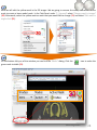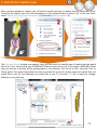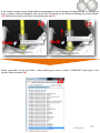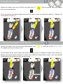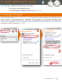
1
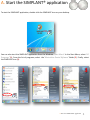
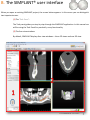
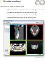
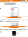
Training manual
All trademarks and company names are the property of their respective owners. Materialise Dental does not waive any rights to its trademarks by not using the symbols ®.
32670193-USX-1310 © 2013 Materialise Dental. All rights reserved.
1
SIMPLANT®
NOTE:
This training manual is designed to kick start the hands-on practice of the SIMPLANT
software.
The manual contains numerous screenshots showing you - feature per feature - exactly
where to click and what do to in the SIMPLANT software.
This manual contains both SIMPLANT Planner (treatment planning) and SIMPLANT Pro
(treatment planning and segmentation) features. Specific Pro features can be found on
the following pages :
pp 15-39 segmentation techniques
pp 41-46 Dual Scan wizard
pp 47-53 Optical Scan wizard
Parts that are exclusively useful for SIMPLANT Pro users will be indicated with the
following icon :
SIMPLANT ® Pro
2
A. Start the SIMPLANT® application
To start the SIMPLANT application, double-click the SIMPLANT icon on your desktop.
2X
You can also start the SIMPLANT application from the Windows ‘Start Menu’. In the Start Menu, select ‘All
Programs’ (1). From the list of programs, select the ‘Materialise Dental Software’ folder (2). Finally, select
the SIMPLANT icon (3).
1
2
3
A. Start the SIMPLANT® application
3
B. The SIMPLANT® user interface
When you open an existing SIMPLANT project, the screen below appears. In this screen you can distinguish
two important areas:
(1) The ‘Task Panel’:
The Task panel guides you step by step through the SIMPLANT application. In this manual we
will be using the Task Panel for practically every functionality.
(2) The four view windows:
By default, SIMPLANT displays four view windows – three 2D views and one 3D view.
B. The SIMPLANT® user interface
4
C. The view windows
Each of the four view windows has a separate color code:
(1) The cross-sectional view (top left window): This view shows the 2D cross-sectional slices.
(2) The axial view (top right window): This view shows the 2D axial slices.
(3) The panoramic view (bottom left window): This view shows the 2D panoramic slices.
(4) The 3D view (bottom right window): This view shows the 3D model.
C. The view windows
5
C. The view windows
Around each of the four view windows you can see a colored border. In the three 2D view windows you can
also notice colored lines. Each of these lines represents a view. For example, the cross-sectional view
window has a blue border and is visible as a blue line in the axial view window and the panoramic view
window.
Notice that when you click a random point in one of the 2D view windows, the other 2D view windows
automatically jump to the slice on which this point is positioned. The same functionality is present in the 3D
view window. When you click a point on the bone model here, the three 2D view windows automatically
jump to the slice on which this point is positioned.
C. The view windows
6
D. View navigation
1. Zoom to fullscreen
To get a more detailed look of each of the four view windows, you can zoom to full screen. You can zoom to
full screen by clicking the ‘Zoom to Full Screen’ icon in the SIMPLANT menu bar (1). Afterwards, click with
the left mouse button in one of the four view windows (2). The window is now zoomed to full screen (3).
Click the ‘Zoom to Full Screen’ icon a second time to zoom out again.
1
2
3
D. View navigation
7
D. View navigation
2. Scroll through the slices in the 2D view windows
In the 2D view windows you can easily scroll through the different slices. There are two alternatives to scroll
through the slices:
A Use the slider bar
B Use the mouse wheel button
A. Use the slider bar
In the 2D view windows you can use the slider bar to scroll through the slices.
B. Use the mouse wheel button
Position the mouse cursor somewhere in the 2D view window area and scroll the mouse wheel to scroll
through the slices.
D. View navigation
8
D. View navigation
3. Zoom in
To get a better look in each of the four view windows, you can zoom in on the images. First, click the ‘Zoom’
icon in the SIMPLANT menu bar (1). In one of the view windows, click and hold the left mouse button and
drag a square around the area that you would like to zoom in on (2). When you release the mouse button
the zoom function is applied (3).
1
2
hold
3
release
D. View navigation
9
D. View navigation
4. Unzoom
To zoom out again, first click the ‘Unzoom’ icon in the SIMPLANT menu bar (1). Click with the left mouse
button somewhere inside the view window (2). The view window is now zoomed out again (3).
1
2
3
D. View navigation
10
D. View navigation
5. Pan
To pan the view, first click the ‘Pan Once’ icon in the SIMPLANT menu bar (1). Position the mouse cursor
somewhere in the view window and click and hold the left mouse button while dragging the mouse to pan
the view (2). Release the mouse button to finish (3).
1
2
hold
3
release
D. View navigation
11
D. View navigation
6. Rotate
To rotate the view, first click the ‘Rotate Once’ icon on the right side of the 3D view window (lower right
window) (1). Position the mouse cursor somewhere in the view window and click and hold the left mouse
button while dragging the mouse to rotate the view (2). Release the mouse button to finish (3).
1
2
3
D. View navigation
12
E. Task Panel
The Task Panel guides you through every step of the software. In the rest of this manual we will explain the
step by step typical workflow of a SIMPLANT project using the Task Panel. The Task Panel consists of
following steps:
1. SIMPLANT® Start:
Here you can open an existing SIMPLANT project file or start a new
SIMPLANT Project by importing CT images.
2. Segment:
SIMPLANT ® Pro
In SIMPLANT you have to create a 3D model from the 2D CT
images before you can start your implant planning . This is
called a “segmentation” and can be done using this part of the Task
Panel.
3. Prepare for planning:
In this step you can draw a panoramic curve, draw a nerve, place
Virtual Teeth or place a bone graft.
4. Plan implants:
In this step the actual planning of the implants takes places. Draw,
specify and modify the implants that you would like to use in your
project.
5. Order SIMPLANT® Guide:
After you have finished your implant planning, you can design and
order a SIMPLANT Guide through the Online Shop.
6. Communication:
Export your project to the SIMPLANT View format, Print
your project or create a screenshot or movie of it.
Tools:
These tools can be used for making measurements in your project
(bone density, distance, angulation).
E. Task Panel
13
1. SIMPLANT® Start
A To start a new SIMPLANT project, click ‘Open Files’.
B You can either work with an existing project or import new CT images:
A Open an existing project.
B Import new CT images.
A. Open an existing project
Select the file you would like to open from the list (1) and click ‘Open file’ (2). Note that the default location
for storing SIMPLANT projects is “C:\DentalData”.
1. SIMPLANT® Start
14
B. Import new CT images
SIMPLANT ® Pro
Navigate to the folder on your computer where the CT images that you want to import are stored. Select
the “.dcm” file (1) and click ‘Open file’ (2) to import the images.
The ‘image selector’ window opens up (3). Here you can select which CT images you want to include in your
SIMPLANT project.
3
1. SIMPLANT® Start
15
First, select the anatomy of the images: Mandible, Maxilla or Both (4).
SIMPLANT will enter the orientation of the CT images (5). Click
or
and select ‘Top’ or
‘Bottom’ to change the orientation (6). If the orientation is not included in the image data you will have to
enter it yourself.
6
5
Hold your mouse cursor over one of the red lines until the
icon appears (7). Click and hold the left
mouse button and drag the mouse cursor to move the red line (8). This changes the area of CT images that
will be included in the SIMPLANT project.
7
8
HOLD
1. SIMPLANT® Start
16
Select whether you would like to skip images or not (9) and click ‘OK’ to import (10).
1. SIMPLANT® Start
17
2. Segment
SIMPLANT ® Pro
2.1. Advanced volume rendering
In SIMPLANT, there is an ‘advanced volume rendering’ 3D visualization tool. This feature immediately shows
an excellent 3D visualization without the use of the conventional segmentation tools.
NOTE: Please take a look at the DVD cover for indications on the system requirements required for this
feature. This feature requires a high quality video card. If your computer does not support this feature, you
will be able to work with the standard volume rendering tool.
When you import Dicom images in SIMPLANT, the ‘3D tresholding’ is automatically generated (1). The
toolbar ‘Visualization settings 3D tresholding’ is also displayed (2).
1
2
You can change the treshold value to show soft tissue (3). To do this drag the ‘Treshold’ slider to the left (4).
3
4
2. Segment
18
You can change the treshold value to show the teeth (5). To do this drag the ‘Treshold’ slider to the right (6).
5
6
You can use the clipping tool (7) to remove the upper teeth and see the occlusal plane of the mandible
teeth. Use the scroll wheel to move the clipping plane up or down
7
You can use the transparency tool to visualize the anatomical structures or implants planned.
2. Segment
19
You can use the transparency tool (8) to visualize the anatomical structures or implants inside the bone.
8
You can also generate a ‘3D X-ray’. In the lower right of the screen click the arrow next to the small skull
icon (9). From the pop-up menu select ‘3D X-ray’ (10). Now the 3D X-ray object is visible. You can rotate the
X-ray object to view it from different angles (11).
11
1010
9
2. Segment
20
2.2. Manual segmentation techniques
SIMPLANT ® Pro
In the previous step we have imported CT images into SIMPLANT. The first thing we need to do is create a
3D model from these 2D CT images. This process is called ‘segmentation’. We will perform this
segmentation by using the ‘Segmentation wizard’.
The Segmentation Wizard
Define the type of anatomy that you would like to segment: the bone model, the teeth or the prosthesis (1)
and click ‘Next’ to continue (2).
1
2
Click an internal bone point in one of the axial slices (3) and click ‘Next’ to continue (4).
3
4
2. Segment
21
The next step is to remove the scatter in the 3D model. SIMPLANT zooms the 3D view window to fullscreen
(5). To remove the scatter, click and hold the left mouse button and drag a circle around the area that you
would like to remove (6). Release the mouse button to finish (7).
5
6
hold
7
release
2. Segment
22
After removing the scatter you can split the 3D model in two separate models: one for the bone and one for
the prosthesis (8). Rotate the 3D model in a way that you have a clear view on the scan prosthesis (9). Click
and hold the left mouse button and drag a circle around the area that you would like to remove to separate
the scan prosthesis (10). Release the mouse button to finish the operation (11). The separated 3D model
now has a different color. Click ‘Next’ to continue to the final step of the Segmentation Wizard (12).
9
8
12
10
hold
11
release
To finalize the 3D model select the quality of the model (13) and click ‘Finish’ (14).
2. Segment
23
Advanced segmentation: scan prosthesis
SIMPLANT ® Pro
When following the Single Scan procedure, the patient wears a special scan prosthesis during the scan. The
scan prosthesis is produced by a dental lab and is fabricated using a mixture of barium sulfate. Because of
this special composition, the prosthesis is clearly visible in the CT images and can be segmented separately.
In this section we will explain how you can perform such a segmentation.
The first thing we need to do is create a segmentation of the patient’s jaw using the ‘Segmentation wizard’.
In the Task Panel under ‘2. Segment’ select ‘Segmentation wizard’ (1). Select ‘Bone’ as anatomic type (2)
and click ‘Next’ to continue (3).
Click an internal bone point (4) and click ‘Next’ to continue (5).
4
Advanced segmentation
24
Now click and hold the left mouse button and drag a circle around the area of the bone model that you
would like to remove (6). Release the mouse button to remove the part (7).
6
hold
7
release
In the 3D model you can notice that part of the teeth of the mandible are attached to the scan prosthesis
(8). We will remove these teeth using a clipped view. To enable clipping, click the clipping icon
(9) .
From the drop-down menu select ‘Axial plane’ (10).
8
Advanced segmentation
25
Scroll to the right slice using the mouse wheel button (11) and remove the bottom teeth from the
prosthesis model (12).
11
12
Scroll with the mouse wheel to navigate through the slices (13) and remove the remaining scatter around
the prosthesis (14).
138
14
Advanced segmentation
26
Click ‘Finish’ to exit the Segmentation Wizard (15).
15
Now we are going to create a duplicate of the mask that we just created. In the SIMPLANT menu, navigate
to ‘Lists>Masks’ (16).
16
In the ‘Masks’ dialog click the ‘Advanced’ button (17) and from the drop-down menu select ‘Duplicate’ (18).
A new copy of the green mask is created (19). This new (yellow) mask will become the mask for the bone
model.
19
Advanced segmentation
27
Now we will edit the yellow mask in the 2D images. We are going to remove the scan prosthesis from this
mask to create a bone model mask. In the Task Panel under ‘2. Segment’ select ‘Change mask in images’
(20). Afterwards, select the yellow mask as mask that you would like to change (21) and select ‘Edit mask in
single slice’ (22).
On the bottom left you of the window you can find the ‘Masks’ dialog. Click the
green mask invisible (23).
Advanced segmentation
icon to make the
28
In the ‘Edit Masks’ dialog select ‘Circle’ as type (24) and select ‘Erase’ (25).
Now you can erase the redundant parts of the yellow mask slice per slice. Click and hold the left mouse
button and trace the area of the mask that you wish to remove (26) (the traced area colors black). Release
the mouse button to finish (27). Notice that the yellow mask has disappeared on the places that you have
traced.
26
hold
27
release
Now scroll to the next slice. Remove the redundant parts of the yellow mask here in the same way as you
did in the previous slice (28-29).
28
hold
29
release
Advanced segmentation
29
Repeat this for every slice in which you have to clean up the yellow mask. In the region of the scan
prosthesis be sure not to erase the bone part of the mask. For example, in slice 19, you can see both bone
and prosthesis material. You can easily distinguish the porous bone parts from the prosthesis parts in the
slices visually (30). Only erase the prosthesis parts from the mask (31).
30
31
Now we need to calculate a 3D object again from the altered yellow mask. Select ‘Calculate a 3D object’
(32). In the ‘Calculate 3D’ dialog select the ‘Yellow’ mask (33), choose the quality of the 3D object (34) and
click ‘Calculate’ (35) to finish.
Advanced segmentation
30
At this point we have created two masks:
- One mask consisting of the bone and the prosthesis (the green mask) (36)
- Another mask consisting of the bone (the yellow mask) (37)
36
37
Now we will rename these two masks. In the SIMPLANT menu select ‘Lists>Masks’ (38). In the ‘Masks’
dialog click the name of the mask with the left mouse button (39). Type the new name for the mask (“Bone
+ Prosthesis” for the green mask and “Bone” for the yellow mask) (40).
38
Advanced segmentation
31
Now we will create a third mask by substracting the yellow mask from the green mask using ‘Boolean
Operations’. This third mask will consist of the prosthesis. In the Task Panel under ‘2. Segment’, select
‘Advanced’ (41). Afterwards, select ‘Boolean operations’ (42).
The ‘Boolean Operations’ dialog appears. Select the green “Bone + Prosthesis” mask as ‘mask A’ (43) and
the yellow “Bone” mask as ‘mask B’ (44) and click ‘Apply’ (45). This creates a new (blue) mask that
represents the separate prosthesis. Rename this mask to “Prosthesis” in the same way that you did for the
other masks (38-40).
Advanced segmentation
32
The next thing we have to do is create a 3D model from this mask. In the Task Panel, select ‘Calculate a 3D
object’ (46). In the ‘Calculate 3D’ dialog, select the blue ‘Prosthesis’ mask (47), select the quality of the 3D
model (48) and click ‘Calculate’ (49).
The result is a separate 3D model of the scan prosthesis (50).
50
Advanced segmentation
33
The final result is a separate segmentation of both the bone model and the prosthesis model (51).
51
Advanced segmentation
34
Advanced segmentation: teeth
SIMPLANT ® Pro
In this section we will explain how you can perform a separate segmentation of the teeth. In the Task Panel
under ‘2. Segment’, select ‘Segmentation wizard’ (1). Select ‘Teeth’ as anatomic type (2). Set the minimum
threshold value to around “1800” (3) and click ‘Next’ to continue (4).
Click with the left mouse button somewhere inside the tooth surface (5). Click ‘Next’ to continue (6).
5
Advanced segmentation
35
Click and hold the left mouse button and drag a circle around the area that you want to remove from the
model (7). Release the mouse button to finish (8).
88
7
hold
release
Use the methode described above to remove the rest of the bone material. Now only the tooth remains (9).
Click ‘Finish’ to end the Segmentation Wizard (10).
9
Advanced segmentation
36
The segmentation is not yet perfect however. When you take a closer look at the green mask in the axial
slices you can see that the edge mask doesn’t correspond to the (white) edge of the teeth (11). In the next
steps we will ‘dilate’ the mask to fix this. In the Task Panel under ‘2. Segment’ select ‘Advanced’ (12).
Afterwards, select ‘Morphology operations’ (13).
11
In the ‘Morphology operations’ dialog, select ‘Dilate’ (14). Set the ‘Number of pixels’ to “1” (15). Select ‘26connectivity’ (16) and click ‘Apply’ to finish (17).
Notice that the newly created yellow mask corresponds with the tooth edge (18)
18
Advanced segmentation
37
In the SIMPLANT menu navigate to ‘Lists>Masks’ (19).
19
In the ‘Masks’ dialog left-click the green ‘Tooth’ mask (20) and click the ‘Delete’ button to remove it (21).
Afterwards, left-click the yellow mask and type “Tooth” to rename this mask (22).
Click the ‘Calculate 3D’ button (23). In the ‘Calculate 3D’ dialog select the yellow ‘Tooth’ mask (24), select
the quality of the 3D model (25) and click ‘Calculate’ (26).
Advanced segmentation
38
We now have completed the separate segmentation of a tooth (27).
27
Advanced segmentation
39
3. Prepare for planning
After opening the project, it can be prepared for the actual planning:
A Dual scan wizard
B Optical scan wizard
C Draw the panoramic curve
D Draw the nerve
E Create Virtual Teeth
F Create bone graft
G Make measurements
SIMPLANT ® Pro
3. Prepare for planning
40
A. Dual Scan wizard
SIMPLANT ® Pro
To be able to use the Dual Scan wizard you need two scans:
(A) a scan of the patient with the scan prosthesis
(B) a separate scan of the scan prosthesis
In the Task Panel under ‘Prepare for planning’ select ‘Dual Scan wizard’ (3).
In the next step, SIMPLANT is going to search for the Dual Scan Markers on the scan prosthesis in the
patient scan (A). The Markers are obviously only located in the area of the scan prosthesis. To prevent
SIMPLANT to search for Markers in the entire 3D model, you need to outline the volume that contains all
the Markers (2). This outlining can be done in the three 2D view windows.
2
In the 2D view windows you can now see a square that indicates the area that SIMPLANT will search for
Markers in. To change this area, move your mouse cursor over one of the edges of such a square until the
mouse cursor changes into following icon (3):
3
Dual Scan wizard
41
Now click and hold the left mouse button and move the mouse cursor to change the dimensions of the
square (4). Release the mouse button to finish the operation (5). Repeat this for all the sides of the square
until the selected area is narrowed down to the area containing the Markers.
5
4
hold
release
The selected area should look like the area selected in the window shown below (6). Only the area of the
scan prosthesis is selected. Make sure all markers are in the box area.
6
Dual Scan wizard
42
Define the location of the prosthesis data (7). Browse for the folder where your CT images are stored (8).
Click ‘OK’ to continue (9).
Adjust the threshold of the prosthesis if necessary (10).
[NOTE: only adjust the treshold if necessary! If protocol was followed, the treshold will not have to be
adjusted]
Outline the volume of the prosthesis in the same way you did in step 4 and 5 (11) . Click ‘Next’ to continue
(12).
11
Dual Scan wizard
43
SIMPLANT now matches the 3D model of the prosthesis on the 3D model of the patient automatically (13).
13
Click ‘Next’ to continue to the last step: Soft tissue creation (14).
14
Dual Scan wizard
44
You can mark the inner surface of the prosthesis and create a 3D object of the soft tissue surface.
Choose if you want to mark or unmark the
surface (15)
15
Choose the marker size (16)
16
Hold the left mouse button and mark the soft tissue surface (17). When you release the mouse button
the 3D object of the soft tissue is created in the 3D view (18).
17
18
Dual Scan wizard
45
Now you can finetune the soft tissue 3D object by rotating the prosthesis and marking or unmarking.
In (19) we unmark a piece of the prosthesis that was incorrectly marked.
19
When you are ready, click ‘Finish’. The result is a 3D object of the prosthesis and a 3D object of the
soft tissue.(20).
20
Dual Scan wizard
46
B. Optical Scan wizard
SIMPLANT ® Pro
To be able to use the Optical Scan wizard you need two scans:
(A) a scan of the patient with the scan prosthesis
(B) an optical scan of the plaster cast or an intraoral scan
If available, you can add a wax-up and an antagonist (or any other additional 3D files from a 3rd party
software).
In the Task Panel under ‘Prepare for planning’ select ‘Optical scan wizard’ (1).
First you need to define the scanner type (2). Select which scanner was used to scan the plaster cast from
the list (3). If your scanner is not listed choose “Other Scanner” (4).
2
3
4
Optical Scan wizard
47
Now you need to locate the plaster cast or intraoral scan data (5). In the ‘Open’ dialog browse for the file (6)
and click ‘Open’ to continue (7).
5
6
5
7
It is now also possible to add additional 3D models like a wax-up or an antagonist. Click ‘Add’ to select
additional files (8). The files will be added in the correct position to your project (9).
9
8
Optical Scan wizard
48
All files have now been imported. This is how they look like before the matching with the CT images (10).
10
Click ‘Next’ in the wizard to go to the Registration step (11).
11
Optical Scan wizard
49
In the following step, three 3D view windows are shown (12):
(1) The 3D view of the patient’s jaw
(2) The 3D view of the plaster cast model
(3) The combined 3D view of the patient’s jaw and the plaster cast model
As you can see in the image below, the position of the plaster cast model does not yet match the position of
the patient’s jaw. In the next step we will match these two positions.
12
Optical Scan wizard
50
The matching of the two 3D models is done based on the information of the tooth
tips. SIMPLANT recognizes the similar geometry of these tooth tips in both 3D models
and matches the models based on this information. However, SIMPLANT can not perform this operation
fully automatic. The user still needs to select the corresponding tooth tips in both 3D models (a minimum of
three tooth tips preferably on dispersed locations in the mouth).
To be able to select the corresponding tooth tips you first need to rotate the separate 3D models (views (1)
and (2)) in order to view them both from a similar perspective (13).
13
First click a tooth tip point with the left mouse button in the 3D view of the patient’s jaw (view (1)) (7). The
point that you selected is now marked as ‘PO1’ (14).
14
Optical Scan wizard
51
Now you can select the same tooth tip in the 3D model of the plaster cast (view (2)). Click the tooth tip
point with the left mouse button (15). The point that you selected also gets marked as ‘PO1’ here (16).
15
Repeat this operation for at least two more tooth tip points (11).
16
Optical Scan wizard
52
In the combined 3D view window (view (3)) you can see that the two 3D models are now matched on each
other (17). Also, the additional 3D models (in this case the wax-up and the antagonist) will move along with
the plaster cast when the position is changed.
17
Click ‘Finish’ to exit the Optical Scan wizard (18).
18
Optical Scan wizard
53
C. Draw the panoramic curve
Select ‘Panoramic curve’ in the task panel (1). Now you can start drawing the panoramic curve in the axial
view (top right window). Click a number of points inside the bone to draw the panoramic curve and doubleclick the last point to finish the curve (2).
2X
1
3. Prepare for planning
54
2
D. Draw the nerve
Select ‘Nerve’ in the Task Panel to start drawing the nerve (1). In the 3D view window, click the entry point
of the nerve in the mental foramen to move to the right slice in the 2D view windows (2). Click ‘Add nerve’
to start drawing the nerve in the 2D view windows (3).
1
2
3
The cross-sectional view window (top left window) is already positioned on the right slice to start drawing
the nerve. In this window, click the left mouse button to define the first points of the nerve (4) (points a and
b). We will draw the rest of the nerve in the panoramic view window (bottom left window). Move the
mouse cursor over to this panoramic view window and continue drawing the nerve here (5) (points c to h).
To finish drawing the nerve, double-click on the last point (point h).
4
5
2X
3. Prepare for planning
55
E. Create Virtual Teeth
In this section we will explain how to place and modify Virtual Teeth.
In the Task Panel under ‘Prepare for planning’ select ‘Virtual Teeth’ (1). You will then enter the Virtual Teeth
wizard (2). First we need to draw a teeth curve. The procedure is the same as drawing a panoramic curve.
We will however draw the curve at tooth level and not at bone level. The virtual teeth are placed along the
path of the teeth curve. You can also draw the curve while scrolling through the axial images, if necessary.
2
1
The axial images will be shown in full screen so you can draw the panoramic curve.
Scroll to a slice in which you can see the tooth tips clearly and draw a panoramic curve that follows the
curvature of the teeth. It is best to draw the curve at the buccal side. (3)
3
Virtual Teeth
56
If you are not pleased with the panoramic curve you have drawn you can click ‘Delete curve’ and draw a
new curve (5). If the curve is well drawn, click the ‘Next’ button to go to the next step (6).
5
6
Select the teeth that you would like to create (7). The teeth will directly be added to the 3D view (8). Click
‘Finish’ to exit the wizard (9).
7
8
9
Virtual Teeth
57
The three Virtual Teeth have been created (10). However, their position is not yet perfect. In the next steps
we will show how you can change the position of the teeth. First we will move the 3 teeth together. To
select all teeth hover over one of the teeth. A tooth symbol will be added to your cursor:
When you
see this icon ‘double click’ to select all teeth (11). You will see the positional icon appear.
10
11
double click
Use the arrows to move the teeth. You can do this in 2 ways. Click on an arrow to move the teeth in that
direction (12). The other way to move the group of teeth is to click on an arrow and hold the left mouse
button. Then drag the mouse in the direction in which you want to move the teeth (13). This is the fastest
way to make changes to the teeth positions.
12
click
13
Hold & drag
Virtual Teeth
58
It is also possible to rotate the teeth. To do this use the round symbol in the middle of the positional icon.
Either click the icon (14) or click, hold and drag the mouse (15).
14
15
Hold & drag
click
To make changes to the position of a single tooth click on a tooth to select it (16). Don’t double click or you
will select all teeth. Now it is possible to move and rotate the selected tooth. In (17) you can see an
example of a rotated tooth.
17
16
Virtual Teeth
59
We can also change the size of the virtual teeth. We can do this by using the rectangular shapes (18). Click
and hold the left mouse button. If we drag with the mouse we can change te size of the teeth in that
direction. In this example we’ll shrink the teeth by moving the mouse to the right and enlarge them by
moving to the left (19).
18
19
Hold & drag
Changing the size of a single tooth is done in the same way. Select a single teeth and use the rectangular
icon (20) (21). The positional icon will change with the viewing direction of the 3D view. This way we can
move the teeth in every clinical direction.
Hold
20
21
Drag
Virtual Teeth
60
When we have a fully edentulous jaw we can create a full set of teeth by using the virtual teeth wizard.
First select the outer tooth of the bridge (22). Then move your mouse to the other outer tooth, hold in the
Shift key and click the tooth. All the teeth in between will be selected (23).
23
22
+ Shift
The result is a full arch of virtual teeth (24).
24
Virtual Teeth
61
F. Create graft volume
In this section we will create and modify a graft volume. In the Task Panel under ‘Prepare for planning’
select ‘Graft volume’ (1). Afterwards, select ‘Add recipient area’ (2).
To create a graft volume, click and hold the left mouse button an draw a circle around the area where you
would like to place the bone graft (3). When you release the mouse button, a blue volume appears (4). This
blue volume is the graft volume.
3
hold
4
release
Graft volume
62
Now you can modify the graft volume that you have selected. In the Task Panel click the arrow next to ‘Pull
locally’ (5). From the drop-down menu select ‘Augment locally’ (6). Now you can increase the thickness of
the graft volume by clicking somewhere on it with the left mouse button (7). In the same way you can
reduce the thickness of the graft volume by using the ‘Reduce locally’ tool.
7
Next we can review the dimensions of the graft volume that we have just created. In the Task Panel select
‘Graft volume Properties & List’ (8). Afterwards, select ‘Graft volumes List’ (9).
Graft volume
63
In the ‘Graft volumes’ window, you can check the dimensions of the bone graft (10).
Graft volume
64
G. Make measurements
Before you start placing implants you might want to make some measurements
on the bone area where you would like to place the implant. You can:
A Measure distance
B Measure angle
C Measure density
D Profile line
A. Measure distance
Click the measure icon on the bottom of the Task Panel (1). Click the first point of the measurement (2).
Move the mouse cursor to measure the distance in respect to the first point (3). Click the second point of
the measurement (4).
1
3
4
2
B. Measure angle
Click the measure angle icon on the bottom of the Task Panel (1). Click the first point of the angle (2). Click
the second point of the angle(3). Click the third point of the angle (4).
1
3
4
2
3. Prepare for planning
65
C. Measure density
You can measure the average bone density in a surface within the bone. You have the option to measure
within a square surface or within an elliptical surface.
Click one of the two measure bone density icons on the bottom of the Task Panel (1). Click the first point of
the measurement (2). Click and hold the left mouse button to drag a circle around the area that you are
interested in (3). Release the mouse button to see the results of the measurement (4).
1
3
4
2
hold
release
D. Profile line
You can create a profile line of the bone density.
Click the profile line icon on the bottom of the Task Panel (1). Click the first point of section of the bone
that you want to calculate the profile line for (2). Click the second point of the line(3). The profile line is now
shown (4).
1
3
4
2
3. Prepare for planning
66
4. Plan implants
4.1. The implant library
Here you will find an introduction on how to use the implant library. To access the implant library select
‘Implant’ from the menu (1), then ‘Libraries’ (2) and finally ‘Implants’ (3).
1
2
3
The implant library consists of following tab pages:
A Implant
B Abutment
C Fixation Screws
D SIMPLANT Guide Solutions
A
B
C
D
4. Plan implants
67
A. Implant
On this tab you get an overview of all the available implants in the SIMPLANT software. On this tab,
following areas can be distinguished:
a ‘Choose your SIMPLANT Guide’
b ‘Choose your implant manufacturer’
c ‘Choose your implant’
d ‘Choose your compatible abutment’
e ‘SIMPLANT Guide solutions compatible with your implant choice’
f ‘Show Preview’
4. Plan implants
68
a. Choose your SIMPLANT® Guide
Here you can choose which SIMPLANT Guide you would like to use in advance of selecting your implants.
This way only the compatible implants will be shown. For instance, when you select ‘Compatible with Astra
Tech Implant System’ only those implants that are compatible with the Astra Tech Implant System guide will
be visible. You also have to select a SIMPLANT Guide type if you want to see a preview of the tubes when
planning an implant.
b. Choose your implant manufacturer
Here you can choose the implant manufacturer and product line of implants you would like to use. On top
you can select if you would like to see all the implant brands or only your favorite implant brands (1).
If you select ‘Show Favorites’ only your favorite implant brands and their logos are shown (2). If you select
‘Show All’, all implant brands are shown (3). Right-click on an implant brand and select ‘Add manufaturer to
favorites’ to add the implant brand to the favorites (4).
2
3
4
69
Click the
sign to open up an implant manufacturer’s product line overview (5), and select a product
line from the list (6).
5
6
c. Choose your implant
Here you can select a specific implant you would like to use (1). If you click the ‘Details’ button (2), the
‘Implant parameters’ dialog pops up (3).
3
When you right-click on an implant you can choose to set it as the default implant for your mandible and/or
maxilla projects (4).
4. Plan implants
70
Some implants are compatible with the Immediate Smile – Featuring ATLANTIS Abutment solution. When
planning such an implant, you will be able to order a patient-specific ATLANTIS Abutment together with the
SIMPLANT SAFE Guide. These implants have the ATLANTIS icon in the top left corner of the ‘Details’
button(6).
6
It is also shown in the top left corner of the implant preview window (7).
7
4. Plan implants
71
d. Choose your compatible abutment
Here you can select a specific abutment you would like to use (1). Only the abutments that are compatible
with the selected implant are shown here. If you click the ‘Details’ button (2), the ‘Abutment parameters’
dialog pops up (3).
3
e. SIMPLANT® Guide solutions compatible with your implant choice
In this area all the SIMPLANT Guide solutions are shown that are compatible with the implant you have
selected.
f. SIMPLANT® Guide solutions compatible with your implant choice
In this area all you can see a 3D preview of the implant you have selected.
4. Plan implants
72
B. Abutment
On this tab you get an overview of all the available abutments in the SIMPLANT software. This tab is very
similar to the ‘Implant’ tab.
4. Plan implants
73
C. Fixation Screws
On this tab you get an overview of all the available fixation screws in the SIMPLANT software. This tab is
also very similar to the ‘Implant’ tab.
4. Plan implants
74
D. SIMPLANT® Guide solutions
On this tab you can find some more information on the different SIMPLANT Guide solutions. The SIMPLANT
Guide systems are ordered by category. You can see which manufacturers have a SAFE system.
4. Plan implants
75
4.2. Planning implants
Select ‘Create or change an implant’ in the Task Panel to start placing implants.
There are two ways to place an implant:
A ‘Place an implant’: 1-click method
B ‘Draw an implant’: 2-click method
After placing the implants you can:
C Specify the implant type
D Change the position and length of the implant
E View the implant properties
F View the implants list
G Check for collisions
A. Place an implant
Select ‘Place an implant’ in the Task Panel (1). In one of the 2D view windows, position your mouse cursor
on the location where you would like to place the implant (2). Press the left mouse button once to drop the
implant on that location (3).
1
2
3
4. Plan implants
76
B. Draw an implant
Select ‘Draw an implant’ in the Task Panel (1). With this function you can define an implant with two mouse
clicks.
1
The first click defines the point of entry for the implant (2). After you have selected this point, you can
define the length and orientation of the implant by moving the mouse cursor (3). Finally, when you are
satisfied with the implant size and orientation, you can click a second time with the left mouse button to
place the implant (4).
2
3
4
4. Plan implants
77
C. Specify the implant type
After you have placed the implant, you still need to specify the type of implant that you would like to use.
To specify the implant type, first click somewhere on the implant surface to select it (1). In the Task Panel,
select ‘Match and specify selected implant’ (2) followed by ‘Specify implant’ (3).
1
2
3
The ‘Implants library’ window now appears. Here you can select the specific type of implant that you would
like to use. First, choose what type of SIMPLANT Guide you want to use (4). If you select a SIMPLANT Guide
type you will see a preview of the guiding tubes in you planning. This can be a SAFE, Universal, Pilot or
Classic guide. Then select the product line that you would like to use (5). Finally, select the implant that you
would like to use (6), the abutment you would like to use (7), and click ‘OK’ (8) to make the changes
effective in your planning.
4
6
5
7
8
78
Because you have selected a SIMPLANT Guide type you will see a preview of the guiding tubes. You can see
the position of the tube in the cross-sectional view (9), in the 3D view (10) and in the panoramic view (11).
If you click on the tube in the 3D view as shown in (10) you will see a pop-up with information on drill
length and implant holder length.
9
10
11
If you select a system with different tube types (ExpertEase or Universal) you can change this type by right
clicking on the implant (12), clicking on ‘Change tube type’ (13) and clicking on a different tube type (14).
You can see the open sleeve in (15).
12
14
13
15
4. Plan implants
79
If we choose a system which allows different prolongations we can change the tube position. An example of
such a system is Biomet Navigator. We can do this by clicking on the tube and holding the mouse button
(16). Move the mouse up the move the guiding tube up (17).
16
Hold
17
Hold
Please remember: to see the tubes in your planning you have to select a SIMPLANT Guide type in the
implant library window (18).
18
4. Plan implants
75
D. Change the position and length of the implant
During the planning, you might want to change the position or length of the
implants. Three types of modifications to the implant can easily be made:
A Move the implant
B Rotate the implant
C Change the length of the implant
A. Move the implant
Position the mouse cursor on the implant area (1) until you see the move icon appear next to your mouse
cursor:
Click and hold the left mouse button and move the mouse cursor to drag the implant to a new location (2).
Release the mouse button to finish (3).
1
2
hold
3
release
4. Plan implants
81
B. Rotate the implant
Position the mouse cursor on one of the two rotate icons (1)
next to your mouse cursor:
until you see the rotate icon appear
Click and hold the left mouse button and move the mouse cursor to rotate the implant (2). Release the
mouse button to finish (3).
1
2
hold
3
release
C. Change the length of the implant
Position the mouse cursor on one of the two following icons
icon appear next to your mouse cursor:
(1) until you see the ‘change length’
Click and hold the left mouse button and move the mouse cursor to change the length of the implant (2).
Release the mouse button to finish (3). Notice that SIMPLANT automatically jumps to the next possible
implant within the product line that you were using.
1
2
hold
3
release
4. Plan implants
82
D. View the implant properties
After you have have created the implant you might want to review its properties. This can be done in the
‘Implant properties’ window. To open this window click with the left mouse button somewhere on the
implant (1). In the Task Panel select ‘Implant Properties & List’ (2). Finally, select ‘Implant Properties’ (3).
1
3
2
In the ‘Implant properties’ window (4) you can check the properties of the implant and change them if
necessary. On the bottom of this window you can indicate at which tooth position the implant is located
(5). This will also change the implant label and make it easy to find your implants in the planning.
4
5
5
4. Plan implants
83
E. View the implants list
If you have placed many implants in one project, it can be useful to have an overview of all the implants.
The ‘Implants List’ provides such an overview. To access this list select ‘Implant Properties & List’ in the Task
Panel (1) followed by ‘Implants List’ (2). This opens up the implants list (3)
1
2
3
F. Check for collisions
An important feature of the SIMPLANT software is the ‘Collision detection’ function. When an implant
collides with a nerve or another implant (1), a warning message automatically appears on your screen (2).
The software also generates a list of all the collisions detected in your project.
1
2
4. Plan implants
84
5. Order SIMPLANT® Guide
A The ordering of a SIMPLANT Guide consists of two steps:
A The design of the SIMPLANT Guide
B The ordering of the SIMPLANT Guide in the ‘Online Shop’
A. The design of the guide
In the Task Panel select ‘Request SIMPLANT Guide’ (1). Select what type of support you would like to use:
bone-, mucosa- or tooth-supported (2). SIMPLANT will now show you the possible SIMPLANT Guide
solutions for the implants that you have placed. Select the SIMPLANT Guide solution that you would like to
use (Classic or SAFE) (3) and click ‘Next’ (4).
1
2
3
4
5. Order SIMPLANT Guide®
85
B. SIMPLANT® SAFE Guide
If you have selected a SAFE SIMPLANT Guide as guidance type, you don’t have to enter any drill diameters
(5a). Click ‘Next’ to continue (5b).
5a
5b
5. Order SIMPLANT Guide®
86
Select the type of order process that you would like to use: ‘FastTrack’ or ‘Traditional’ (6). Check the box
next to “Tooth extractions needed” if you are planning on doing tooth extractions (7). Click ‘Mark tooth’ (8).
In the 3D view, click with the left mouse button to mark the tooth that you are going to extract (9).
6
7
8
5. Order SIMPLANT Guide®
87
Check the box next to “I want to add remarks” if you would like to add some remarks (10). Type your
remarks in the remarks area (11). Click ‘Next’ to continue (12).
10
11
12
5. Order SIMPLANT Guide®
88
Check the box next to “Create a preview of the guide” if you would like to create a preview (13). Select the
3D model representing the bone (14). Click ‘Show preview’ (15). SIMPLANT now calculates a preview of the
SIMPLANT Guide which is shown in the 3D view (16). Click ‘Finish’ to continue to the Online Shop (17).
13
14
15
16
89
5. Order SIMPLANT Guide®
B. Ordering the guide
The SIMPLANT software now directs you to the Online Shop web page. If you are
a new customer you will have to register first. Click ‘Register now’ (1).
1
The registration page appears (2). Check the box next to “I have read and agree to the Framework
Agreement” and click ‘Continue to Next step’ to continue.
2
5. Order SIMPLANT Guide®
90
On the second registration page (3) check the box next to “I have read and agree
to the Privacy policy” and click ‘Continue to Next step’ to continue.
3
On the third registration page (4) enter your username and password. Click ‘Continue to next step’ to
continue.
4
5. Order SIMPLANT Guide®
91
On the fourth registration page (5) enter your CCKey if you have one. If you don’t
have a CCKey, click ‘I don’t know my SIMPLANT CCKey’ and fill out your company
details. Then click ‘Continue to next step’ to continue.
5
On the final registration page (6) enter your contact infomation and click ‘Finish registration’ to continue.
The Online Shop login web page now appears .
6
5. Order SIMPLANT Guide®
92
Enter your username and password and click ‘Login’ to continue.
You are now directed to the first page of the Online Shop (7). You will see a list of
what you are ordering. If you want to order additional components check the
‘additional components’ section below.
7
8
If you want to order an additional component, click the
Click ‘To next step’ to continue.
sign (8) on the right of that component.
5. Order SIMPLANT Guide®
93
You can order an ATLANTIS Abutment from the additional products list (9).
Click on the plus-icon to order an ATLANTIS Abutment (10).
9
10
You can now fill in all info needed to create the ATLANTIS Abutment (11). Select the implant or implants for
which you want to order the ATLANTIS Abutment and select the tooth number from the dropdown list (12).
You also have to select to which dental laboratory you want to send the pre-order (13).
11
12
13
The ATLANTIS Abutment will now be ordered along with your SIMPLANT Guide.
When an ATLANTIS Abutment was ordered, it can be loaded in your SIMPLANT planning using the
‘import ATLANTIS Abutment’ functionality in the file menu.
5. Order SIMPLANT Guide®
94
You are directed to the second page of the Online Shop (14). Add some remarks if necessary.
14
Check that the invoice and delivery data are correct and click ‘To next step’ to continue (15).
15
5. Order SIMPLANT Guide®
95
The Scheduling & Payment page of the Online Shop is now shown (16). Click the ‘The surgery is already
scheduled.’ box to select an intervention date.
16
The final page of the Online Shop is shown (17). Review the summary, and check the box to agree with the
‘limitation of liability’ and click ‘Place order’ to finalize the procedure.
After the order is uploaded to our server, an order confirmation is shown.
17
5. Order SIMPLANT Guide®
96
You will receive a confirmation e-mail when we receive your order. You can follow-up on your orders on our
website ‘MySIMPLANT.com’. You can access the site by clicking on the link on the left hand side of the
online shop ( 18).
18
The website ‘MySIMPLANT.com’ will open in your browser and you have to log in with your Online Shop
account. (19).
You can also access ‘MySIMPLANT.com’ on your mobile device!
19
You can now see the status of your order by clicking on ‘My Orders’ in the menu (19). Then you select the
planning of which you want to check the status by clicking on the patient name (20).
19
20
5. Order SIMPLANT Guide®
97
Now you can see more details about the status of your order. When we need your approval because we
applied some minor changes to your order the status of your order will be ‘Approval Required’. You can give
your approval directly through ‘MySIMPLANT.com’ (21).
21
5. Order SIMPLANT Guide®
98
6. Share your cases
You can share your case with referrals, dental technicians, colleagues and yourself by making a planning
available for review on our iPad app, SIMPLANT Team-Up!.
We will explain the 4 buttons:
A. Share the current project
B. View shared cases
C. View case communication
D. Activity Stream
A B C D
A. Share the current project.
To share the project that you are working on click on the “Share current project’ button (1).
1
Log in with your Online Shop account (2).
2
6. Share your cases
99
Once you are logged in you will see the “Share Case” screen (3).
You can add comments to your case (4). The information about the project is shown under ‘Plans’ (5).
Check if this information is correct before sharing your case.
3
4
5
6
Click ‘Continue’ to go to the next step (6).
6. Share your cases
100
On the next screen you can add images to the case (7). These will be viewable on the iPad app.
To add images click the ‘Add Photo’ button (8). Select one or more photos in the ‘Open File’ Dialog (9) and
click the ‘Open’ button (10).
7
8
9
10
6. Share your cases
101
The images will be added to the case (11). Click ‘Continue’ (12) to go to the next step.
11
12
On the next screen you can select the people with whom you want to share the case. Enter their e-mail
address and click ‘Add’ (13). You can add as many people as you want. Click ‘Finish’ to share the case (14).
13
14
6. Share your cases
102
The case will be uploaded to the server so it will be available on the iPad app (15).
15
If you change something to your planning and save the planning, SIMPLANT will ask if you also want to
apply these changes to the shared case (16). If you choose Yes the planning will be uploaded again with
your changes.
16
6. Share your cases
103
B. View shared cases
Once the case has been uploaded the ‘Share Case’ button will be disabled. You can click on the ‘Show
shared cases’ button to view all the cases you have shared (17).
17
Here you have an overview of all cases you have shared with your referrals, dental technicians and
colleagues (18). You can select each of them and view the comments (19) and the images that have been
shared (20). On the ‘Sharing’ tab (21) you can add or remove people.
21 20
18
19
6. Share your cases
104
C. Show the case communication
You can see the comments of your colleagues by clicking on the ‘Communication’ icon (20).
20
On this screen you can see who made notes in the iPad app about the case (21).
21
6. Share your cases
105
Headquarters
Materialise Dental NV
Technologielaan 15
3001 Leuven
Belgium
Phone: +32 16 39 66 20
Fax: +32 16 39 66 22
E-mail: [email protected]
US
E-mail: [email protected]
Germany
E-mail: [email protected]
France
E-mail: [email protected]
Spain
E-mail: [email protected]
Italy
E-mail: [email protected]
Japan
E-mail: [email protected]
106