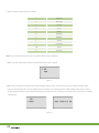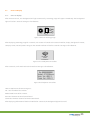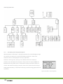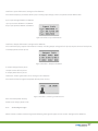
1
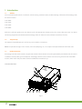
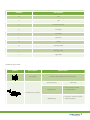
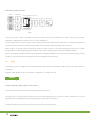
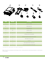
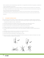
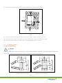
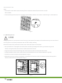
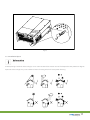
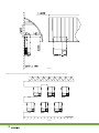
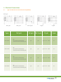
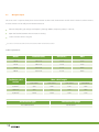
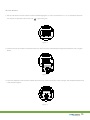
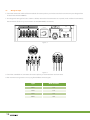
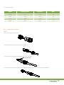
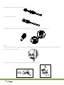
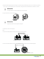
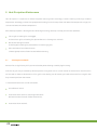
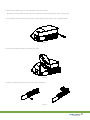
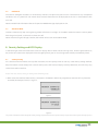
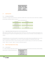
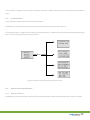
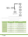
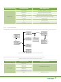
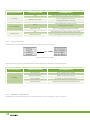
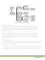
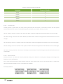
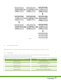
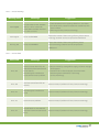
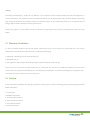
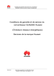
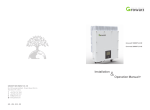
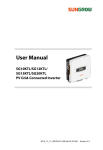
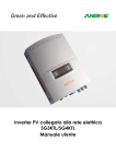
THE POWER OF ASTRONERGY
INSTALLATION & OPERATION MANUAL FOR
INVERTER OF 10~20KTL
INSTALLATION & OPERATION MANUAL
FOR INVERTER OF 10~20KTL
1. Introduction
1.1
1.2
1.3
1.4
Validity
Target Group
Product Overview
Safety
7. Operation Modes
7.1
7.2
7.3
Normal mode
Fault mode
Shutdown mode
8. LCD Display
2. Unpacking
2.1
2.2
Unpacking and Inspection
Information of Label
3. Mounting
3.1
3.2
3.3
Safety instruction
Selecting the Installation Location
Installation guidance
4. Electrical Connections
4.1
4.2
4.3
4.4
Types of Grid Structure and
Connection Compatibility
Wiring AC Output
Wiring DC Input
RS485 cable connection
5. Heat Dissipation Maintenance
5.1
5.2
Cleaning Fans and Grills
Exchanging Fan
6. Commission the Inverter
8.1
8.2
8.3
8.4
8.5
Country Setting
General LCD display
Operate by knock
Data checking and parameters setting
Inverter faulty messages
9. Communitions
9.1
9.2
9.3
9.4
Astronergy Net
Astronergy Vision
Astronergy Pano
Astronergy WebBox
10. Trouble Shooting
10.1
10.2
General question
Error Messages displayed on LCD
11. Specifications
12. Astronergy Factory Warranty
13. Warranty Conditions
14. Contact
1
1. Introduction
1.1Validity
This installation guide contains installation, commissioning, communication, trouble shooting. information of Astronergy CHPI
KTL series inverters:
CHPI 10KTL
CHPI 12KTL
CHPI 18KTL
CHPI 20KTL
With this installation guide, users are able to install and operate the inverters easily. This manual does not cover any details
concerning equipment connected to the Astronergy CHPI KTL. Store this manual where accessible at all times.
1.2
Target Group
This manual is for qualified persons such as PV system installers or electricians.
Notes: For possible changes in this manual, Chint Solar(Zhejiang) Co., Ltd. accepts no responsibilities to inform the users.
1.3
Product Overview
Astronergy CHPI KTL series inverters are grid-tied inverters which convert DC current generated by PV modules into AC current
and feed it into the public grid in threephase. Astronergy CHPI KTL series inverters are multi-string inverters with multi-MPP
trackers, which mean they are able to connect to different PV module arrays.
Inverters Overview:
Fig 1.1
2
Position
Description
A
LCD
B
LED
C
PV input terminals
D
DC Switch
E
AC output
F
RS232 lid
G
RS485
H
Series Number
I
Warning Label
J
Type label
Symbol on the inverter
Symbol
Description
Explanation
Tap symbol
Indicates display operation (see Section 6).
Green/constant
Operation
Red/constant
1. Fault-- contact installer
2. Standby module
Red/flashing
1. Fans Fault-- contact installer
2. Software update
Inverter status symbol
3
Grid-tied PV system Overview:
Input A
DC Breaker
Astronergy CHPI KTL Inverter
AC Breaker Energy meter Public grid
Input B
DC Breaker
Fig 1.2
As drawings shown above, a complete Grid-tied PV system consists of PV modules, PV inverters, public grid and other
components. Moreover, PV inverters always act as key components.
The Astronergy CHPI KTL series inverters may only be operated with PV generators (modules and cabling) with protective
insulation. Do not connect any source of energy other than PV modules to the Astronergy CHPI KTL series.
When design a PV system contains Astronergy CHPI KTL series inverters or any other Astronergy inverters, the system
designing software AstronergyDesign (download from site: www.astronergy.com) will provide adequate supports.
Notes: If PV modules of the PV system require POSITIVE or NEGATIVE GROUND, or the capacitance relative to ground of the
modules is large, please contact Astronergy for technical support before installation.
1.4Safety
Astronergy CHPI KTL is designed to use worldwide, hence the inverters meet different safety standards of variety countries
and regions.
VDE-AR-N 4105; BDEW; CEI 0-21; IEC 62109 1/2; VDE0126-1-1; RD1663; G59; CE
DANGER!
Danger to life due to high voltages in the inverter!
All work on the inverter may be carried out by qualified personnel only.
The appliance is not to be used by children or persons with reduced physical, sensory or mental capabilities, or lack of
experience and knowledge, unless they have been given supervision or instruction.
Children should be supervised to ensure that they do not play with the appliance.
4
CAUTION!
Danger of burn injuries due to hot enclosure parts!
During operation, the upper lid of the enclosure and the enclosure body may become hot.
Only touch the lower enclosure lid during operation.
CAUTION!
Possible damage to health as a result of the effects of radiation!
Do not stay closer than 20 cm to the inverter for any length of time.
Grounding the PV generator
Comply with the local requirements for grounding the PV modules and the PV generator.
Astronergy recommends connecting the generator frame and other electrically conductive surfaces in a manner which
ensures continuous conduction and ground these in order to have optimal protection of the system and personnel.
CAUTION!
Possible damage the PV modules as a result of Identification of String Failure!
The Astronergy CHPI KTL Inverter is equipped with a system which recognizes total failure of individual strings or part-strings.
2. Unpacking
2.1
Unpacking and Inspection
Before opening the packing box of Astronergy CHPI KTL, please note that whether there are any visible external damages.
Once open the packing box, please check the delivery for completeness and for any visible external damages of the inverter. If
there are anything damaged or missing, please contact your dealer. Complete delivery should contain as follows.
5
Fig 2.1
Item
Number
Description
A
1
CHPI KTL inverter
B
1
Mounting frame
C
1
Waterproof cover
D
6/8
Explosion screw
E
2
RS485 connector
F
1
Cable gland for AC connection
G
4
M4 cross recessed countersunk head screws
H
3
M6 socket head cap screws
I
2
Flat mat
——
1
Warranty(not show in the picture)
——
1
User manual (not show in the picture)
Hint: Number of D is 6 for CHPI 10/12 KTL, and 8 for CHPI 18/20 KTL.
Notes: Though the packaging box of Astronergy CHPI KTL is durable, please treat the packing box gently and avoid dispose
the packing box.
6
2.2
Information of Label
The label contains information as below:
• The inverter type/model (Model Name);
• The certificates and approvals (Certificate Number and Logos at
the bottom of thelabel);
• Specifications of the inverter (From UDCmax to Operation
Ambient Temperature).
3. Installation
3.1
Safety instruction
Danger to life due to fire or explosion
• Despite careful construction, electrical devices can cause fires.
• Do not install the inverter on easily flammable materials and where
flammable materials are stored.
Risk of burns due to hot enclosure parts
Mount the inverter in such a way that it cannot be touched inadvertently.
• All electrical installations shall be done in accordance with the local and national electrical codes. Do not remove the casing.
Inverter contains no user serviceable parts. Refer servicing to qualified service personnel. All wiring and electrical installation
should be conducted by a qualified service personnel.
• Carefully remove the unit from its packaging and inspect for external damage. If you find any imperfections, please contact
your local dealer.
• Be sure that the inverters connect to the ground in order to protect property and personal safety.
• The inverter must only be operated with PV generator. Do not connect any other source of energy to it.
• Both AC and DC voltage sources are terminated inside the PV Inverter. Please disconnect these circuits before servicing.
• This unit is designed to feed power to the public power grid (utility) only. Do not connect this unit to an AC source or
generator. Connecting Inverter to external devices could result in serious damage to your equipment.
7
• When a photovoltaic panel is exposed to light, it generates a DC voltage. When connected to this equipment, a photovoltaic
panel will charge the DC link capacitors.
• Energy stored in this equipment’s DC link capacitors presents a risk of electric shock. Even after the unit is disconnected
from the grid and photovoltaic panels, high voltages may still exist inside the PV‐Inverter. Do not remove the casing until at
least 5 minutes after disconnecting all power sources.
• Although designed to meet all safety requirements, some parts and surfaces of Inverter are still hot during operation.
To reduce the risk of injury, do not touch the heat sink at the back of the PV‐Inverter or nearby surfaces while Inverter is
operating.
3.2
Selecting the Installation Location
This is guidance for installer to choose a suitable installation location, to avoid potential damages to device and operators.
1) The wall selected to install the inverter must be strong and firm enough to support and bear the weight of the inverter for
a long period time. (Refer to Chapter 11 Specifications)
2) The location selected must be suitable for inverters’ dimension. (Refer to Fig 3.2 Required Clearances)
3) Do not install the inverter on structures constructed of flammable or thermo labile materials.
4) Never install the inverter in environment of little or no air flow, nor dust environment.
5) The Ingress Protection rate is IP65 which means the inverter can be installed outdoors and indoors.
6) Do not expose the inverter to direct sunlight, in order to avoid the power and efficiency derating caused by excessive
heating.
7) The humidity of the installation location should be 0~95% without condensation.
8) The ambient temperature of the inverter should be ‐25 °C~+60 °C.
9) The installation location must be freely and safely to get at all times.
10) Vertically installation and make sure the connection of inverter must be downwards. Never install horizontal and avoids
forward and sideways tilt.( Refer to drawings below)
Fig3.1
8
11) Notice the minimum clearances of the inverter. (Refer to Fig 3.2 Required Clearances).
Fig3.2
12) Do not install the inverter near television antenna or any other antennas and antenna cables.
13) Do not install the inverter in living area, the noise caused by the machine may affect on daily life.
14) For security reasons, don’t install the inverter in place where the children can reach.
3.3
Installation guidance
3.3.1 Mounting the Bracket
In order to avoid electrical shock or other injury, inspect existing electronic or plumbing installations before drilling holes.
To mount the inverter on the wall, we should mount the bracket to the wall firmly first of all
a) Bracket of CHPI 10KTL/12KTL
b) Bracket of CHPI 18KTL/20KTL
Fig3.3
9
Hint: Data units in mm
Steps:
• Drill holes for screws while use the mounting frame as template.6 holes for CHPI 10/12KTL and 8 for
CHPI 18/20KTL.
• Fix the mounting frame on the wall as the figures shown below, combine as the screws as the Items Fig 2.1 shows (items D)
Fig 3.4
3.3.2 Mounting Inverter
Falling equipment can cause serious or even fatal injury, never mount the inverter on the bracket unless you are sure that the
mounting frame is really firmly mounted on the wall after carefully checking.
After the bracket is firmly mounted on the wall, then mount the inverter on the bracket.
• Rise up the CHPI KTL a little higher than the bracket. Considering the weight of CHPI KTL, you need to hang on the
inverter. During the process please maintain the balance of the CHPI KTL.
• Hang the inverter on the bracket through the match hooks on bracket and the back of the inverter.
• Installed one M6*10 screw at each side of inverter to reliable fixed it on the wall. Please reference in Fig3.5(b).
• Connect the inverter to the earth. Please reference in Fig3.6.
• Recommend awning installation, the purpose is to extend the inverter service life and reduce the power derating of the
inverter. The dimensions of awning refer to Fig 3.8.
a)
10
Fig 3.5
b)
Fig 3.6
3.3.3 Installation layout
Avoid exposing inverter to direct sunlight, rain or snow to extend the inverter service life despite the IP65 protection degree.
Exposure to the sunlight may cause additional internal heating which will cause power derating.
Fig 3.7
11
Fig 3.8
Roof
500mm
>400mm
1000mm
>450mm
More than one inverter need to be installed, the dimensions below should be considered.
Ground
Fig 3.9
12
4. Electrical Connections
4.1
Types of Grid Structure and Connection Compatibility
Grid type
TN-C grid
Types
TN-S grid
TN-C grid
TN-C-S grid
TT grid
IT grid
TN-S grid
TN-C-S grid
TT grid
IT grid
CHPI 10KTL
yes
(N and PE of inverter both
should connect to PEN of grid.)
yes
yes
yes, if UN-PE < 30V
no
CHPI 12KTL
yes
(N and PE of inverter both
should connect to PEN of grid.)
yes
yes
yes, if UN-PE < 30V
no
CHPI 18KTL
yes
(N and PE of inverter both
should connect to PEN of grid.)
yes
yes
yes, if UN-PE < 30V
no
CHPI 20KTL
yes
(N and PE of inverter both
should connect to PEN of grid.)
yes
yes
yes, if UN-PE < 30V
no
13
4.2
Wiring AC Output
You must install a separate three-phase circuit-breaker or other load disconnection unit for each inverter in order to ensure
that the inverter can be safely disconnected under load.
Measure the public grid voltage and frequency (Voltage: 400Vac; Frequency: 50Hz; in 3-Phase);
Open the breaker between the PV inverter and utility;
Screw’s torsional force is 8 kg/cm;
* Specification of AC breaker: CHPI 10KTL/12KTL:25A/400V CHPI 18KTL/20KTL:50A/400V
Cable requirements:
Model
Diameter(mm)
Area(mm²)
AWG
10KTL
2.05~4.11
4~16
12~6
12KTL
2.05~4.11
4~16
12~6
18KTL
2.59~4.11
6~16
10~6
20KTL
2.59~4.11
6~16
10~6
Conductor cross
section
14
Max. cable length
CHPI 10KTL
CHPI 12KTL
CHPI 18KTL
CHPI 20KTL
6.0 mm²
53m
44m
29m
26m
10.0 mm²
88m
73m
49m
44m
16.0 mm²
141m
116m
78m
71m
AC connector type
Available wire gauge
AC Screw Terminal
6.0-16.0 mm²
AC Screw Terminal:
1. The AC side terminals of the inverter are like the following figure, it is clear to confirm that ‘L1, L2, L3’ represents three live
line output, ‘N’ represents neutral line and ‘
‘ is grounding line.
N
L1
L2
L3
Fig 4.2.1
2. Connect five standard cables into relevant terminals. The five cables should be put through the protection shell, as figure
below.
N
L1
L2
L3
Fig 4.2.2
3. Fasten the protection shell onto the bottom of the inverter, make sure the four screws are tight, the completed appearance
is like the below figure.
N
L1
L2
L3
Fig 4.2.3
15
4.3
Wiring DC Input
1 Check the connection cables of the PV modules for correct polarity and make sure that the maximum input voltage of the
inverter never exceed 1000Vdc.
2 The diagram drawing of DC side is shown as below, notice that the connectors are in paired (male and female connectors).
The connectors for PV arrays and inverters are H4 (AMPHENOL) connectors;
MPP Tracker A
MPP Tracker B
Do not disconnect under load!
NL
DC switch
1
L2
L3
RS-232
RS-485
Fig 4.3.1
Fig 4.3.2
3 Check the assembled DC connectors for correct polarity and connect them to the inverter.
4 The maximum string currents are varying from different inverter types.
16
Type
Max.current
10KTL
15A
12KTL
17A
18KTL
23A
20KTL
26A
5 Cable requirements:
4.4
Model
Diameter(mm)
Area(mm²)
AWG
10KTL
2.05
3.332
12
12KTL
2.05
3.332
12
18KTL
2.05
3.332
12
20KTL
2.05
3.332
12
RS485 cable connection
Type 1:
1. Unscrew the plastic connector.
2. Make the RS485 cable go through the connector.
3. Put two heat shrink tubes onto the front head of RS485 cable.
Heat shrink tube
4. Insert the two metal head into relevant small cupreous hole, and fasten the connection by soldering.
17
5. Make the heat shrink tubes wrap the joint.
6. Assemble the connector.
7. Connect the RS485 connector onto the inverter. Make sure the connection matched (‘1’ to ‘1’, ‘2’ to ‘2’).
Type 2:
1. Please loosen four screws, take down the RS485 waterproof cover from inverter. If you don’t choose RS485 as communication
method, keep it on the inverter.
2. Slightly loosen the swivel nut, remove the filler-plug from the M16 cable gland.
18
3. Make the cable through the hole of cable gland and put the cable into the RS485 terminals, fix all cables with screwdriver
(‘1’to’1’, ‘3’to’3’, ‘2’ to the shielding layer or no connection.). The type of cable is recommended as “KVVRP22/2*1.5mm2”.
Pull cables outwards to confirm whether they are installed firmly
4. Plug in two terminals. Cover the fix board.
Tighten 4 pcs screws first, then tighten cable gland.
5. Tighten 4pcs screws and cable gland.
Note:
1) As to the connection between inverters, please refer to the following figure.
1 23
1 23
RS 485 terminal of the inverter 1
1 23
1 23
RS 485 terminal of the inverter 2
2) As to the connection between inverter and ShineWebBox (ShinePano), please refer to the following figure.
1 23
RSRS485
inverter
485terminal
terminal of
of the
the inverter
COM
Comport
port
Com
of of
Astronergy WebBOX
Shine WebBOX
19
5. Heat Dissipation Maintenance
Heat dissipation is important to reduce the power derating when Astronergy inverters working under high ambient
temperature. Astronergy inverters are equipped with cooling fans on the top of the shell. When the temperature is high, fans
start work to lower the ambient temperature.
Once the output power is derating because of too high warming, some tips can help you solve such problems:
•
The air grills or cooling fans are clogged.
To clean the air grills and cooling fans please refer to 5.1 Cleaning Fans and Grills.
•
One or two cooling fans failed.
To exchange the cooling fans please refer to 5.2 Exchanging Fans.
•
Poor ventilation of installation location.
Choose appropriate installation location before mounting.
5.1
Cleaning Fans and Grills
Maintain fans and grills every half a year to reduce the power derating caused by high warming.
If the fans or grills are just covered by soft dust particles, using tools such as vacuum cleaner to clean the fans. And if user has
no such tools or there are obstructions in fans, grills or the cooling area of inverter, you need to clean the fans and grills after
they are took apart from the inverter.
1. Please disconnect the DC and AC connection.
•
Turn off the DC switch.
•
Disconnect the DC terminal. (You might need some
tool to disconnect the male and female terminals)
•
Disconnect the AC terminal.
20
2. Remove the protecting plants at the bottom of CHPI KTL inverter.
Remove the inverter from mounting bracket, and place inverter horizontally on clean and dry place.
3. Screw off the screws to open the cover with suitable tool, then fans will be seen, as figures below:
Fig 5.1.1
4. Pull out the white connectors with some tinny tools.
Fig 5.1.2
5. Take away the fans from the cover and clean them thoroughly.
Fig 5.1.3
21
6. When finishing cleaning, put back the fans in reverse order.
5.2
Exchanging Fan
Sometimes the heat dissipation error occurred because the cooling fans failed, under such circumstances, one need exchange
the cooling fans.
6. Commission the Inverter
1) Remove all covers from the PV array.
2) Check the PV and AC voltage.
3) Plug in the PV input.
Fig 6.1
4) Turn the DC Disconnect to position "I".
5) If the inverter is connected with PV panel arrays and the input voltage is higher than 300Vdc, while the AC grid is not
connected yet, LCD will display messages in order as below:
Company info
Basic info
State info
The LCD will display “ AC V outrange “at State info and the LED turns red.
Please check all information on the LCD, operate by knocks you will see the different parameters.
Single knock to Light the backlight
State info (single knock) Input info
(single knock) Output info
6) Turn on the AC breaker between inverter and grid, the system will operate automatically.
7) Under normal operating conditions, the LCD displays ‘Power: xx.xx Kw’ at State info, this is the power feed into grid. The
LED turns green.
8) Check the time and date of inverter as follow:
Single knock to Light the backlight
State info (Thrice knock)
Inverter info (single knock)
System
Time(double knock), if they are not correct, please set them, refer to 6.3.4 or 6.4.3 text line.
9) Finish commissioning.
7. Operation Modes
7.1
Normal Mode
In this mode, the inverter works normally and LED turns green.
Whenever the DC voltage is higher than 350Vac, inverter converts power to grid as generated by the PV panels;
Whenever the DC voltage is lower than 300Vac, the inverter will work in waiting state and attempt to connect the grid. In
waiting state the inverter consumes just enough power generated by the PV panel to monitor the internal system
Notes: The inverter starts up automatically when DC power from the PV panel is sufficient.
22
7.2
Fault Mode
The internal intelligent controller can continuously monitor and adjust the system status. If inverter finds any unexpected
conditions such as system fault and inverter fault, the fault information will be displayed on the LCD. In fault mode the LED
turns red.
Notes: Detailed fault information refers to Chapter 10.2 ERROR messages displayed on LCD.
7.3
Shutdown Mode
Inverters automatically stop running during periods of little or no sunlight. In shutdown mode the inverters take no power
from the grid and panel, and the LCD and LED turns off.
Notes: If the PV string DC voltage is too low, the inverter will also turn to Shutdown Mode.
8. Country Setting and LCD Display
In the lower right corner of inverter there is the LCD display. We can check inverter running status, historical generation data,
etc, on the LCD screen. Items displayed can be changed by knock; you can also change some inverter parameters by knock.
8.1
Country Setting
If it is the first time the inverter starts up after installation, LCD will quickly switch to and stay at the country setting interface.
Only the inverter is set to comply with a certain country rule, it will work and display normally. Otherwise, LCD will always stay
at the ’Please select’ interface.
Please finish the country setting according to the following steps:
1. When at the first interface ‘Select country :’, the option is ‘VDE0126’ in default. By single knock, countries will vary from one
to another, for example, ‘France’, as Fig 8.1.2.
Fig 8.1.1
Fig 8.1.2
* If you have ordered the inverter with specific country settings, the parameters have been preset in factory and you don't need to operate this step any more.
23
2. There are eleven countries/rules to select:
1
VDE0126
2
Germany
3
France
4
Italy
5
Greece
6
Hungary
7
Belgium
8
Turkey
9
Denmark
10
Spain
11
UK-G59
Note: if you can’t find the country you want, please directly select ‘VDE0126’.
3. When it comes to the country you want, double knock to enter, as Fig 03.
Fig 8.1.3
4. When enter the confirm interface, there are two options ‘NO’ and ‘YES’, and the cursor will stay at ‘NO’ in default, single
knock to shift between ‘NO’ and ‘YES’, double knock to confirm your selection. When at ‘NO’, double knock will exit, when
at ‘YES’, double knock will set up. After the setting is successful, the LCD will display ‘Set Country OK’, and inverter will reboot
automatically.
Fig 8.1.4
24
8.2
Power on Display
8.2.1
Power on display
After inverter restarts, LCD background will light automatically. Astronergy Logo will appear immediately. The background
light will last for 2 seconds. See Fig8.2.1 for reference.
Fig8.2.1:Power on Astronergy Logo
After displaying Astronergy Logo for 2 seconds, LCD screen will switch to the second interface, display the figure of inverter,
company name, inverter’s power rating, etc. The second interface will last for 3 seconds. See Fig8.2.2 for reference.
PV Inverter
18 KTL
Fig 8.2.2:The second power on interface
After 3 seconds, it will switch to the third interface. See Fig8.2.3 for reference.
Fig8.2.3:The third power on interface
Here are explanation of items on Fig8.2.3:
No. : serial number of this inverter.
Model:model name of this inverter.
Main Ver: firmware version of control board
Comm Ver: firmware version of communication board .
After displaying information of the third interface for 3 seconds, the background light will turn off.
25
LCD Display Overview
8.2.2
LCD Display when background light off
After the power on information is displayed automatically and the background light
turns off, the LCD display will switch to the following Interface 1. There are 4
interfaces, which can be displayed in turn by single knock.
Interface 1: Running status. See Fig 8.2.4 as reference. The first line displays
inverter’s status description, for example, in faulty state it will display ERROR and
followed with faulty codes, which is convenient to compare with error code list in
manual. The second line displays inverter’s states name; and the third line displays
energy generated today, and the forth line displays the total energy generated since
installation.
Fig8.2.4:Interface 1: Running status
26
Interface 2: Input information. See Fig8.2.5 for reference.
This interface displays parameters of PV input, including input voltage, current, and power of each MPP tracker
V-pv: input voltage of MPPT1 and MPPT2
I-pv: input current of MPPT1 and MPPT2
W-pv: input power of MPPT1 and MPPT2
Fig8.2.5:Interface 2: Input information
Interface 3: Output information. See Fig8.2.6 for reference.
This interface displays output information of inverter, including output voltage of each phase, output current of each phase,
and output power of each phase.
Fig8.2.6:Interface 3: Output information
V: output voltage of each phase
I: output current of each phase
P: output power of each phase
Interface 4: 24 hour’ generation curve. See Fig8.2.7 for reference.
This interface shows the generated power of every hour this day.
Fig8.2.7:Interface 4: 24 hour’s generation curve
Max: maximum power of today
Power curve: today’s power curve
8.2.3
Connecting messages
When inverter started to connect to grid, the following message will appear on LCD screen. See Fig8.2.8 for reference.
27
Fig8.2.8 Connect to gird interface
8.3
Operate by knock
8.3.1
Knock type and definition
The inverter can support three kinds of knock: single knock, double knock and thrice knock. Each kind of knock has different
function. Refer to specified definition in Table 8.1.
Table 8.1 Knock definition list
8.3.2
Knock type
Definition
Single knock
Down
Double knock
Enter
Tri - three knock
Esc
Knock four times
Unlock LCD
Light background light and single knock to check running information
Before light the background light, the three types of knock functions the same, which is just lighting the background.: just
light the background . Note that the background lighting will automatically turn off if there is no knock detected in 10
seconds.
During cloudy days or in the area of low light, it’s inconvenient for users to check inverter running information such as status,
input data, output data, energy generated. In this case user can light the background and check those data by single
knock, a single knock will switch LCD screen to a following interface. The interface display on LCD screen will circle as follows:
Fir8.2.4 -> Fig8.2.5 -> Fig 8.2.6 -> Fig8.2.7 -> Fig8.2.8, and then again Fig8.2.4.
8.4
Data checking and parameters setting
8.4.1
First level menu
It is a little bit different to enter the first level menu, note that using thrice knock to enter first level menu instead of double
knock. Fig 8.4.1 is interface of first level menu.
28
In this interface, a single knock will switch the index to next item, a double knock will enter the corresponding second level
menu.
8.4.2
Second level menu
In first level menu, double knock will lead to next level menu.
The followings are second level menu interfaces for each first level menu items, shown in Fig 8.4.2
In second level menu, a single knock will switch the index to next item, a double knock will enter the corresponding third level
menu. And a thrice knock will back to first level menu.
Enter
Fig 8.4.2 Second level menu for each first level menu items
8.4.3
Third level menu and explanations
8.4.3.1
Working information
The followings are third level menu interfaces for each second level menu items of working information, shown in Fig 8.4.3.
29
Enter
down
Enter
down
Enter
down
Note: if there is " * " d isplay
before the time number, t hat
mean the time number isn't
correct
down
Fig 8.4.3 Third level menu interface of working information
Explanations of each items in third level menu interface of working information: State information:
Table 8.2 Working information sub-items explanation
Second level menu
Inverter info
30
Third level items
Item explanation
State: Normal
Inverter running status
Power: xxx.xx
AC gross output power
E_day
Energy produced today
E_all
Energy produced since installation
Input info
Inverter input parameters
V-pv xxx/xxx
PV input voltage for each MPP tracker
I-pv xx.x/xx.x
PV input current for each MPP tracker
P-pv xxx/xxx
PV input power for each MPP tracker
Output info
Inverter output parameters
V: xxx.xxx.xxx
AC output voltage for each phase
I: xx.x/xx.x/xx.x
AC output current for each phase
Second level menu
Inverter info
8.4.3.2
Third level items
Item explanation
P: xxx/xxx/xxx
AC output power for each phase
Power chart
histogram of generation power
Maxrve
Maximum output power of inverter
Power info
Generation power information of inverter
P_Factor
Power factor
Q
Reactive power
GridFreq
Utility grid frequence
Historical information
The followings are third level menu interfaces for each second level menu items of historical information, shown in Fig 8.4.4.
Enter line
More
Enter
Enter
Fig 8.4.4 Third level menu interface of historical information
Explanation of each items in third level menu interface of working information: State information:
Table 8.3 Historical information sub-items explanation
Second level menu
Third level items
Item explanation
Error1: xxx
Error2: xxx
Error Record
Error3: xxx
Five latest error records
Error4: xxx
Error5: xxx
More
More error record
31
Second level menu
Third level items
Item explanation
7 Days
Title indicate this is latest 7 days running data
MM:DD: xxxx.x Kwh
Format is Month:Date, xxxx.x is
energy generated in that day.
Month
Title indicate this is every month’s
running data in this year
MM: xxxx.x Kwh
xxxx.x is energy generated in that month.
Year
Title indicate this is latest 10 years running data
20XX: xxxx.x Mwh
xxxx.x is energy generated in the corresponding year.
E in 7Days
E in Each Month
E in Each Year
8.4.3.3
Property information
The followings are second level menu interfaces of property, shown in Fig 8.4.5.
Enter
Fig 8.4.5 Property information
Explanation of each items in third level menu interface of working information: State information:
First level menu
Second level items
Item explanation
No.:xxxxxxxxxx
Serial number of this inverter
Model:GTGF00xxxx
Model name of this inverter.
Main Ver:0D0.9
Firmware version of Control Board
Comm Ver:0C0.9
Firmware version of Communication Board
Property
8.4.4
Parameters set and auto test
The followings are setting information in second level menu and its submenus, shown in Fig 8.4.6.
32
Enter
Enter
Enter
Enter
Enter
Enter
Enter
Fig 8.4.6 setting second level menu and its sub-menus
8.4.4.1
Set inverter’s COM address
When communicating with monitoring software or device, the software or device may regard inverter’s COM
address as communication address (Also may use inverter’s serial number as communication address).The COM
address could be assigned. The second level menu “Set COM Addr” of setting is to set inverter’s COM address.
Set fixed COM address:
Input password‐>Setting‐>Set COM addr‐>Set Manual, “Current Addr” is the current address of inverter.”COM
Addr Up”add address. ”COM Addr Up” decrease address .Single knock to change value of fixed address, double
knock enter next manual. Choose “YES”to save changes, and LCD screen will display “Set Addr OK! Current Addr
XXX”, see Fig 8.4.6 for reference.
8.4.4.2
Set language
To change inverter’s displaying language, please select Setting->Set language, then LCD screen will display current language
type, single knock to change current language, double knock will save changes and displays “Set Language OK! Current
Language English” see Fig 8.4.6 for reference.
The inverter provides five languages: Italian, English, German, Spanish, and French. The number on Set language interface is
sequence number of these five languages, the sequence number and its corresponding language are shown in Table 8.5
33
Table8.5 sequence number of languages
8.4.4.3
Language
Sequence Number
Italian
0
English
1
German
2
Spanish
3
French
4
Set inverter time
Inverter provides a system clock; user must set the system time after installation, as the historical statistic data for a period
were based on the clock. User can set the following time parameters: year, month, day, hour, minute.
Set year: Setting->Set time->Set year->Year up or Year down->knock to change year. Thrice knock to exit and save changes.
Set month: Setting->Set time->Set month->Month up or Month down->knock to change month. Thrice knock to exit and save
changes.
Set date: Setting->Set time->Set date->Date up or Date down->knock to change date. Thrice knock to exit and save changes.
Set hour: Setting->Set time->Set hour->Hour up or Hour down->knock to change Hour. Thrice knock to exit and save changes.
Set minute: Setting->Set time->Set minute->minute up or minute down->knock to change minute. Thrice knock to exit and
save changes.
8.4.4.4
Auto test function
Auto test function is to check the inverter's protection when grid is abnormal, including over voltage, under voltage, over
frequency, and under frequency.
To run auto test function please select Setting->Auto test, then double knock to start auto test function. It’s required to
connect inverter to computer and run a test software in computer.
Auto test procedure
1
34
2
3
4
5
6
9
8
7
10
11
12
13
Fig 8.4.7
8.5
Inverter faulty messages
When system fault or inverter error occurs, inverter will display faulty message or error code on LCD screen.
8.5.1
System fault
System fault is related to the solar system, it may be caused by PV panels wiring, AC wiring, or AC grid faults.
The followings are all system faulty messages displayed on inverter:
System fault message may display on LCD
Explanation and suggestion
Auto Test Failed
Auto test didn’t pass
No AC Connection
No utility, no grid connected
PV Isolation Low
Insulation problem
Residual I High
GFCI current high
Output High DCI
Output current DC offset too high
35
System fault message may display on LCD
Explanation and suggestion
PV Voltage High
PV panel voltage too high
AC V Outrange
Grid voltage out of range
AC F Outrange
Grid frequency out of range
8.5.2
Error message
Inverter errors are problems come from interior inverter.
ERROR CODE
OPERATION
Error: 100
Fan fault
Error: 101
Communication fault
Error: 103
EEPROM fault
Error: 104
Model Fault
Error: 117
Relay Fault
Error: 119
GFCI Fault
Error: 121
Control board communication Fault
9. Communication
9.1AstronergyNet
AsronergyNet is a monitoring software applied to monitor Astronergy inverters via RS232 port or Bluetooth module. With the
special designed functions and friendly compact UI, it can comprehensively meet users’ requirements for system monitoring
and bring unprecedented user experience.
Fig 9.1
36
Features:
Monitor and record current data and of inverters.
Record historical data.
Monitor and record event information of inverter.
Connect computer and inverter via RS232 and RS485 port (wire connection) or Bluetooth module (wireless connection).
Remote access available for local area network
Notes: Users are able to monitor the inverter after the setting of software. Detailed information about setting and functions
refer to the AstronergyNET Manual.
9.2AstronergyVision
AstronergyVision is a wireless monitoring device, which consists of a power monitor and a number of transmitters, and one
AstronergyVision can monitoring 1 to 6 inverters. The transmitters transmit the running data collected from photovoltaic
inverters to the monitor and display the data onto the monitor screen, including data of generated energy, the gross
generated energy and the generation income obtained from the above-mentioned data through some simple calculations,
indoor temperature, date and time, as well as CO2 emissions.
Features:
Monitor and transmitter communicate via wireless communication technology
External transmitter, with IP65 waterproof and dustproof.
A monitor can simultaneously communicate with six transmitters.
Communication distance between monitor and transmitter : 30 meter.
Power supply option: built-in battery slot, an external DC power supply.
Easy installation, and convenient to use it.
Fig 9.2
Notes: The Monitor should be kept indoor. For detailed information, please refer to AstronergyVision Manual.
37
9.3AstronergyPano
It is the latest intelligent monitoring master, specially designed for solar power plant. Using stable Linux operating system with
high-speed CPU, it can smartly present solar system status through friendly user interface on 8-inch large color touch screen.
Fig 9.3
Features:
A multi-functional and high-performance communication data logger; Keep user informed of the system’s status at any
time.
Massive storage with flexible parameters setting, system information management, error prompt and record.
Collects data and uploads information over the internet in near real-time to Astronergy Server platform.
Connect with inverter: RS485 and Zigbee (Wireless module).
8 inches touch screen(*option): support hand writing and USB mouse.
9.4AstronergyWebBox
It is a cost-effective and compact monitoring device, specially designed for solar power plant. Using stable Linux operating
system with high-speed CPU, it can smartly record your system features. AstronergyWebBox Provides local storage, easy
wireless and TCP/IP configuration, and presents plant data over Internet.
Features:
A multi-functional and high-performance communication data logger;
Keep user informed of the system’s status at any time.
Massive storage with flexible parameters setting, system information
management, error prompt and record.
Fig 9.4
Collects data and uploads information over the internet in near real-time to Astronergy Server platform.
38
10. Trouble Shooting
Our quality control program assures that every inverter is manufactured to accurate specifications and is thoroughly
tested before leaving our factory. If you have difficulty in the operation of your inverter, please read through the following
information to correct the problem.
10.1
General question
For General question, please visit www.astronergy.com, and find the Q&A column.
10.2
Error Messages displayed on LCD
An error message will be displayed on the LCD screen when a fault occurs. The faults consist of system fault and inverter fault.
You may be advised to contact Astronergy in some situation, please provide the following information.
Information concerning the inverter:
• Serial number
• Model number
• Error message on LCD
• Short description of the problem
• Grid voltage
• DC input voltage
• Can you reproduce the failure? If yes, how?
• Has this problem occurred in the past?
• What was the ambient condition when the problem occurred?
Information concerning the PV panels:
• Manufacturer name and model number of the PV panel
• Output power of the panel
• Voc of the panel
• Vmp of the panel
• Imp of the panel
• Number of panels in each string
If it is necessary to replace the unit, please ship it in the original box.
39
10.2.1 System fault
System fault (system faults are mainly caused by system instead of inverter, please check the items as instructed below before
replacing inverter)
Error message
Description
Suggestion
AC V Outrange
Utility grid voltage Is out of
permissible range.
1. Check grid voltage.
2. Check AC wiring, especially the ground wire.
3. If the error message still exists despite the grid voltage being
within the tolerable range, contact Astronergy.
AC F Outrange
Utility grid frequencyout of
permissible range.
1. Check AC wiring and grid frequency.
2. If the error message is displayed despite the grid frequency
being within the tolerable range, contact Astronergy.
Insulation problem
1.Check if panel enclosure ground properly.
2.Check if inverter ground properly.
3.Check if the DC breaker gets wet.
4.Check the impedance of PV (+) & PV (-) between ground
(must be more than 8 MΩ). If the error message is displayed
despite the above checking passed, contact Astronergy.
Leakage current too high
1.Restart inverter.
2.If error message still exists, contact Astronergy.
Output High DCI
Output current DC offset too high
1.Restart inverter.
2.If error message still exists, contact Astronergy.
PV Voltage High
1. Disconnect the DC wire immediately.
The DC input voltage is exceeding 2. Check the voltage of each PV string with multimerter.
the maximum tolerable value.
3. If the voltage of PV strings are lower than 1000V(+15V),
contact Astronergy.
Auto Test Failed
Auto test didn’t pass.
PV Isolation Low
Residual I High
40
Restart inverter, repeat Auto Test, if problem still
exist, contact Astronergy.
10.2.2 Inverter warning
Warning code
Warning100
Meanings
For CHPI 10KTL/12KTL: Problem
with fan 1 or fan 2.For CHPI
18KTL/20KTL: Problem with fan 1,
fan 2, fan 3 or fan 4.
Suggestion
1. Check whether there is anything above fans, clear them;
2. Turn off dc switch, rotate fan blade with screwdriver, then
restart inverter.
3. If Warning still exist, Contact Astronergy.
Warning103
Fail to read EEPROM.
Restart the inverter. If the warning still exist, please contact
Astronrgy customer service to replace the COM board.
Warning 105
Fail to write EEPROM.
Restart the inverter. If the warning still exist, please
contact Astronrgy customer service to replace the
COM board.
10.2.3 Inverter fault
Error code
Meanings
Suggestion
Error: 101
Communication board has not
received data from control board
for 10 seconds.
Electromagnetic Interference
cause communication problem.
1. Restart inverter by cutting off DC supply, and Error message
will disappear.
2. If the error 101 is often displayed, the environment
Electromagnetic Interference is too strong.
Contact Astronergy.
Error: 103
data from control board for 10
seconds.
Restart inverter, if problem still exist, Contact Astronergy.
Error: 117
Electromagnetic Interference
cause
Restart inverter, if problem still exist, Contact Astronergy.
Error: 119
communication problem.
Restart inverter, if problem still exist, Contact Astronergy.
Error: 121
Control board has not received
data from Communication board
for 5S.
Restart inverter, if problem still exist, Contact Astronergy.
41
11. Specifications
Input Data
CHPI 10KTL
CHPI 12KTL
CHPI 18KTL
CHPI 20KTL
Max. DC power
10500W
12500W
18700W
20800W
Max. DC voltage
1000V
1000V
1000V
1000V
Start Voltage
350V
350V
350V
350V
PV voltage range MPPT
180V-1000V
180V-1000V
180V-1000V
180V-1000V
MPP voltage range/
nominal voltage
300V-1000V/
600V
300V-1000V/
600V
300V-1000V/
600V
300V-1000V/
600V
Full load DC voltage range
400V-800V
400V-800V
400V-800V
400V-800V
Max. input current
15A / 15A
17A / 17A
23A / 23A
26A / 26A
Max. input current per string
20A
20A
20A
20A
Number of independent
MPP trackers/strings per
MPP tracker
2/2
2/2
2/2
2/3
Max. AC apparent power
10kVA
12kVA
18kVA
20kVA
Max. AC output power
10kW
12kW
18kW
20kW
Nominal AC output power
9kW
10.8kW
16.2kW
18kW
Max. output current
16A
19A
28.6A
32A
AC nominal voltage; range
3/N/PE, 230V/400V; 184~275V
3/N/PE, 230V/400V; 184~275V
3/N/PE, 230V/400V; 184~275V
3/N/PE, 230V/400V; 184~275V
AC grid frequency; range
50Hz - 6/+5Hz
50Hz - 6/+5Hz
50Hz - 6/+5Hz
50Hz - 6/+5Hz
Power factor
0.8leading- 0.8laging
0.8leading- 0.8laging
0.8leading- 0.8laging
0.8leading- 0.8laging
THDI
<3%
<3%
<3%
<3%
AC grid connection type
Three phase
Three phase
Three phase
Three phase
Max . efficiency
98%
98%
98%
98%
Euro-eta
97.5%
97.5%
97.5%
97.5%
MPPT efficiency
99.5%
99.5%
99.5%
99.5%
DC reverse polarity protection
yes
yes
yes
yes
DC switch for each MPPT
yes
yes
yes
yes
Output over current protection
yes
yes
yes
yes
Output AC overvoltage
Protection - Varistor
yes
yes
yes
yes
Ground fault monitoring
yes
yes
yes
yes
Grid monitoring
yes
yes
yes
yes
Integrated all-pole
sensitive leakage current
monitoring unit
yes
yes
yes
yes
Output (AC)
Efficiency
Protection devices
42
General Data
CHPI 10KTL
CHPI 12KTL
CHPI 18KTL
CHPI 20KTL
Dimensions (W / H / D) in mm
740/440/235 mm
29.1/17.3/9.3 inch
740/440/235 mm
29.1/17.3/9.3 inch
740/440/235 mm
29.1/17.3/9.3 inch
740/440/235 mm
29.1/17.3/9.3 inch
Weight
41kg/90.4lb
41kg/90.4lb
60kg/132.3lb
60kg/132.3lb
Operating temperature range
Noise emission (typical)
–25 °C ... +60 °C / (–13 °F ... +140 °F) / With derating above 45 °C(113 °F)
≤ 55 dB(A)
≤ 55 dB(A)
Self-consumption night
<0.5 W
<0.5 W
<0.5 W
<0.5 W
Topology
Transformerless
Transformerless
Transformerless
Transformerless
Cooling concept
Smart cooling
Smart cooling
Smart cooling
Smart cooling
Environmental Protection Rating
IP 65
IP 65
IP 65
IP 65
Relative humidity
0...95%
Non-condensing
0...95%
Non-condensing
0...95%
Non-condensing
0...95%
Non-condensing
DC connection
H4/MC4(opt)
H4/MC4(opt)
H4/MC4(opt)
H4/MC4(opt)
AC connection
Screw terminal
Screw terminal
Screw terminal
Screw terminal
Display
LCD
LCD
LCD
LCD
Interfaces: RS232/RS485/
Bluetooth/RF/Zigbee/Wifi
yes/yes/opt/opt
/opt/opt
yes/yes/opt/opt
/opt/opt
yes/yes/opt/opt
/opt/opt
yes/yes/opt/opt
/opt/opt
Warranty: 5years/10years
yes /opt
yes /opt
yes /opt
yes /opt
Certificates and approvals
VDE-AR-N4105, BDEW, CEI 0-21, RD1669, VDE 0126-1-1, G59, IEC 62109, CE, AS4777, AS/NZS 3100, etc.
Altitude
≤ 55 dB(A)
≤ 55 dB(A)
2000m(6560ft) without derating
Features
12. Astronergy Factory Warranty
This certificate represents a 5 year warranty for the Astronergy inverter products listed below. Possession of this certificate
validates a standard factory warranty of 5 years from the date of purchase.
Warranted products
This warranty is applicable solely to the following products: CHPI 1.5KTL, CHPI 2KTL, CHPI 3KTL, CHPI 4.4KTL, CHPI 5KTL, CHPI
1.5KTL-AS, CHPI 2KTL-AS, CHPI 3KTL-AS, CHPI 5KTL-AS,CHPI 3.6KTL-M2, CHPI 4.2KTL-M2, CHPI 5KTL-M2 , CHPI 10KTL, CHPI
12KTL, CHPI 18KTL, CHPI 20KTL
Limited Product Warranty
( Applicable under normal application, installation, use and service conditions) Astronergy warrants the above listed products
to be free from defects and/or failure specified for a period not exceeding five (5) years from the date of sale as shown in the
Proof of Purchase to the Original purchaser.
43
The warranties described in these “Limited Warranties ” are exclusive and are expressly in lieu of and exclude all other
warranties, whether written, oral, express or implied, including but not limited to, warranties of merchantability and of fitness
for a particular purpose, use ,or application, and all other obligations or liabilities on the part of Astronergy , unless such other
obligations or liabilities are expressly agreed to it in writing signed and approved by Astronergy , Astronergy shall have no
responsibility or liability whatsoever for damage or injury to persons or property, or for other loss or injury resulting from
any cause whatsoever arising out of or related to the modules, including, without limitation, any defects in the modules or
from use or installation. Under no circumstances shall Astronergy be liable for incidental , consequential or special damages
howsoever caused; loss of use, loss of production, loss of revenues are therefore specifically and without limitation excluded
to the extent legally permissible, Astronergy ’s aggregate liability, if any, in damages or otherwise, shall not exceed the invoice
as paid by the customer.
The “ Limited Product Warranties ” described above shall not apply to, and Astronergy shall have no obligation of any kind
whatsoever with respect to, any inverter which has been subjected to:
Misuse, abuse, neglect or accident;
Alteration, improper installation or application;
Unauthorized modification or attempted repairs;
Insufficient ventilation of the product;
Transport damage;
Breaking of the original manufacturers seal;
Non-observance of Astronergy installation and maintenance instruction;
Failure to observe the applicable safety regulations
Power failure surges, lighting, flood, fire, exposure to incorrect use, negligence, accident, force majeure, explosion, terrorist
act, vandalism or damage caused by incorrect installation, modification or extreme weather conditions or other
circumstances not reasonably attributable to Astronergy.
The warranty shall also cease to apply if the product cannot be correctly identified as the product of Astronergy. Warranty
claims will not be honored if the type of serial number on the inverters have been altered, removed or rendered illegible.
44
Liability
The liability of Astronergy in respect of any defects in its PV inverters shall be limited to compliance with the obligations as
stated in these terms and conditions of warranty. Maximum liability shall be limited to the sale price of the product. Astronergy
shall accept no liability for loss of profit, resultant of indirect damage, any loss of electrical power and / or compensation of
energy suppliers within the express meaning of that term.
The warranty rights as meant herein are not transferable or assignable to any third party excepting the named warranty
holder.
13. Warranty Conditions
If a device becomes defective during the agreed Astronergy factory warranty period and provided that it will not be
impossible or unreasonable, the device will be, as selected by Astronergy,
1.Shipped to a Astronergy service center for repair, or
2.repaired on-site, or
3. exchanged for a replacement device of equivalent value according to model and age.
The warranty shall not cover transportation costs in connection with the return of defective modules. The cost of the
installation or reinstallation of the modules shall also be expressly excluded as are all other related logistical and process costs
incurred by all parties in relation to this warranty claim.
14. Contact
If you have technical problems concerning our products, contact your installer or Astronergy. During inquiring, please provide
below information:
1. Inverter type
2. Modules information
3. Communication method
4. Serial number of Inverters
5. Error code of Inverters
6. Display of inverters
45
JIUQUAN,CHINA
RAVENSBURG,
GERMANY
SAN FRANCISCO,
USA
SEOUL,
KOREA
TOKYO,
JAPAN
SHANGHAI,CHINA
HANGZHOU,CHINA
BARCELONA,
SPAIN
BANGKOK,
THAILAND
CORPORATE HEADQUARTERS
SUBSIDIARIES
Chint Solar (ZheJiang) Co., Ltd.
1335 Bin’an Road, Binjiang District
Hangzhou, Zhejiang Province, 310053
China
Tel: + 86 571 5603 1888
Fax: + 86 571 5603 2383
Spain
Chint Solar Hispania S.L.
Paseo de Gracia, 78, 2-2A
08008 Barcelona,
Spain
Tel: + 34 9346 73778
Fax: + 34 9346 73789
Japan
KoyoAstro Co., Ltd.
1-5-6, Higashi-Nihonbashi, Chuo-ku,
Tokyo 103-0004,
Japan
Tel: + 03 5820 2141
Fax: + 03 5820 2142
MANUFACTURING PLANTS
Germany
Astronergy GmbH
Karlstr. 8
88212 Ravensburg,
Germany
Tel: + 49 (0)751 295096-10
Fax: + 49 (0)751 295096-39
Korea
Astronergy Solar Korea
5t h FL. Cowell Bldg, 66-1,
Banpo-Dong, Seocho-Gu,
Korea
Tel: + 82 (0)2 2226 3911
Fax: + 82 (0)2 2226 3910
North America
Astronergy Solar, Inc.
Suite 1125, 795 Folsom Street,
San Francisco, CA 94107
USA
Thailand
Astronergy Solar Korea (Thailand) Co., Ltd.
184/88 Forum Tower 18FL
Ratchadapisek Rd., Huay-Kwang,
Bangkok 10320
Thailand
Tel: + 662 645 4155
Fax: + 662 245 3185
Hangzhou, Shanghai & Jiuquan
Tel: +1 650 392 2777
http://www.astronergy.com
©
1387 P / 05 - 2013