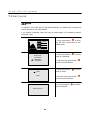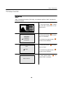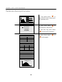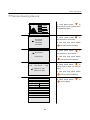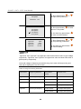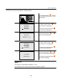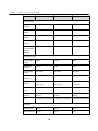
1
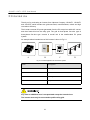
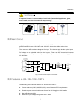
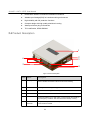
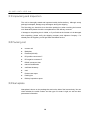
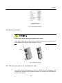
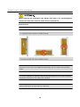
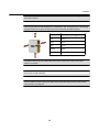
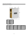
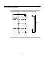
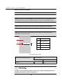
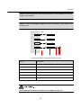
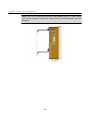
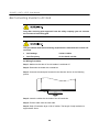
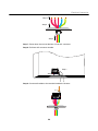
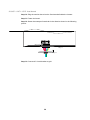
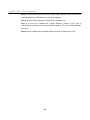
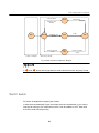
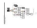
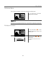
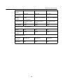
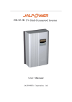
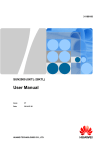
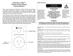
About This Manual
Contents of this Manual
This manual is applied to grid-connected inverters of JSI-10KTL, JSI-12KTL
and JSI-15KTL.
This manual provides detailed product introduction, installation guide, operation guide
and maintenance guide.
This document also provides very important safety instructions about installation,
operation or maintenance.
Target Reader
The manual is provided to installation technicians and users.
The tasks of installation and troubleshooting in this manual must only be performed by
the qualified personnel.
The tasks of menu operation and routine maintenance can be performed by the users.
Retention of this Manual
This document must be stored near installation site and must be available at all times.
Symbols Used
Important instructions contained in this manual should be followed during installation
and maintenance of the inverter. And they will be highlighted by these symbols.
1
JSI-10KTL-12KTL-15KTL User Manual
This symbol indicates a dangerous situation which, if not avoided, will cause
death or severe injury.
This symbol indicates a dangerous situation which, if not avoided, could result
in death or severe injury.
This symbol indicates a dangerous situation which, if not avoided, could cause
minor or moderate injury.
This symbol indicates a situation which can help the equipment optimal operation.
Symbols on the body of the inverter:
High Voltage!
There exists lethal voltage. Please wait at least five minutes and then perform
any work with the inverter after disconnecting the electrical connection of the
inverter.
Risk of Burning !
The surface will be very hot during running. Avoid touching the housing of
equipment except LCD display panle and DC switch when it is working.
2
Contents
About This Manual ................................................................................................... 1
Contents of this Manual.......................................................................................................................... 1
Target Reader......................................................................................................................................... 1
Retention of this Manual ........................................................................................................................ 1
Symbols Used ........................................................................................................................................ 1
1 Safety Instructions ................................................................................................. 1
2 Product Overview ................................................................................................... 5
2.1 Intended Use .................................................................................................................................... 6
2.2 Main Circuit ....................................................................................................................................... 7
2.3 Features of JSI-10K-12K-15KTL Inverters ....................................................................................... 7
2.4 Product Description .......................................................................................................................... 8
3 Installation ............................................................................................................... 9
3.1 Unpacking and Inspection .............................................................................................................. 10
3.2 Packing List .................................................................................................................................... 10
3.3 Nameplate....................................................................................................................................... 10
3.4 Moving Inverter ................................................................................................................................11
3.5 The Requirements of Installation Site ..............................................................................................11
3.6 Dimensions of Inverter .................................................................................................................... 14
3.7 Installation Procedure ..................................................................................................................... 15
4 Electrical Connection ........................................................................................... 19
4.1 General Safety ................................................................................................................................ 20
4.2 Overview of Electrical Installation ................................................................................................... 21
4.3 Terminals Description ..................................................................................................................... 22
4.4 Specification of Cables ................................................................................................................... 23
4.5 Connecting inverter to PV Arrays ................................................................................................... 24
4.5.1 Safety ..................................................................................................................................... 24
4.5.2 Assembling DC Cable to Connector....................................................................................... 25
4.5.3 Wiring Procedure.................................................................................................................... 27
4.6 Connecting Inverter to AC Grid ....................................................................................................... 28
4.7 Grounding the Inverter .................................................................................................................... 31
I
JSI10KTL/12KTL/15KTL User Manual
4.8 Connecting RS485 Cable ............................................................................................................... 32
4.8.1 Installing Monitoring System .................................................................................................. 32
4.8.2 Assembling RS485 Cable to Connector ................................................................................. 33
4.8.3 Connecting RS485 Cable ....................................................................................................... 34
5 LCD Panel and DC Switch ................................................................................. 37
5.1 LCD Panel....................................................................................................................................... 38
5.2 LED Indicator .................................................................................................................................. 38
5.3 Buttons ............................................................................................................................................ 38
5.4 LCD Screen .................................................................................................................................... 39
5.5 Operation mode .............................................................................................................................. 40
5.6 DC Switch ....................................................................................................................................... 41
6 Commissioning ..................................................................................................... 43
7 Menu Operation ................................................................................................... 45
7.1 Overview of Menu ........................................................................................................................... 46
7.2 Default Menu .................................................................................................................................. 47
7.3 Adjust Contrast ............................................................................................................................... 47
7.4 Start Inverter ................................................................................................................................... 48
7.5 Stop Inverter ................................................................................................................................... 49
7.6 Monitor Running Information .......................................................................................................... 50
7.7 Monitor Running Record ................................................................................................................. 51
7.8 Monitor Fault Record ...................................................................................................................... 52
7.9 Parameters Setting ......................................................................................................................... 54
7.9.1 Set Language ......................................................................................................................... 54
7.9.2 Set Time ................................................................................................................................. 55
7.9.3 Setting Total Generated Power Adjustment ........................................................................... 56
7.9.4 Load Default ........................................................................................................................... 57
7.9.5 Set Running Parameter .......................................................................................................... 58
7.9.6 Set Protecting Parameter ....................................................................................................... 59
7.9.7 Set Communication Parameter .............................................................................................. 61
8 Troubleshooting and Maintenance................................................................... 63
8.1 Troubleshooting .............................................................................................................................. 64
8.1.1 Troubleshooting of LED Indicator ........................................................................................... 64
8.1.2 Troubleshooting of faults in LCD Screen................................................................................ 64
8.2 Maintenance ................................................................................................................................... 66
8.2.1 Clean Fan ............................................................................................................................... 66
8.2.2 Replace Fan ........................................................................................................................... 67
II
8.2.3 Clean Air Inlet and Outlet ....................................................................................................... 67
9 Technical Specification ....................................................................................... 69
10 Appendix .............................................................................................................. 73
10.1 Exclusion of Liability...................................................................................................................... 74
10.2 Contact Us .................................................................................................................................... 75
III
1
Safety Instructions
About this Chapter
This chapter describes very important safety instructions. Please read “Safety
Instructions” carefully before any work with the inverter.
1
JSI10KTL-12KTL-15KTL User Manual
The inverter is designed and tested according to international safety requirements.
But as all electrical and electronic equipments, certain precautions should be
observed during installing, operating and maintaining.
Incorrect operation or work performed incorrectly can result in damage to:
The life and well-being of the operator or the third party
The inverter and other properties that belong to the operator or the third party
Therefore in order to reduce risk of injury and ensure the safety of the inverter, you
must carefully read and follow all instructions, cautions and warnings.
First disconnect the inverter from utility grid!
Even when the inverter is disconnected, lethal voltages still exists within
the inverter.
Before any maintenance work, you should wait for at least five minutes and
then perform work.
All tasks of installation and maintenance must only be performed by qualified
personnel.
They are trained specially.
They have read this manual, and comprehend all operation methods and
related safety instructions.
All electrical installations must be in accordance with local and national
electrical codes.
2
Safety Instructions
Only after receiving prior approval from the utility company and qualified
personnel installing the inverter, you can connect the inverter to the utility grid.
All cables must be firmly attached, undamaged, properly insulated and
adequately dimensioned.
When choosing the installation site, this ingredient to ensure that there is no
electromagnetic interference with other electrical and electronic equipments
must be taken into consideration.
Risk of damage to the inverter due to improper modification.
Never modify the inverter or other components of the inverter. Otherwise it will
lead to loss of any and all warranty right.
Any malfunction that can impair inverter safety must be repaired immediately
before the inverter is switched on again.
Please contact your local authorized personnel if any maintenance is required.
3
JSI10KTL-12KTL-15KTL User Manual
Electrostatic discharge can damage the inverter.
During replacing or installing the inner components, the technical personnel
should take appropriate protective measures such as electrostatic bracelet.
All safety instructions and warning labels on the inverter body;
Must be clearly visible
Must not be removed, covered, pasted
These regulations should also be followed:
The regulations related to the electricity fed into the grid
The safety instructions related to the PV arrays
4
2
Product Overview
About this Chapter
This chapter introduces intended use, main circuits, features and its constituent parts.
5
JSI10KTL-12KTL-15KTL User Manual
2.1 Intended Use
Thank you for purchasing an inverter from Jalpower Company. JSI10KTL, JSI12KTL
and JSI15KTL serial inverters are grid-connected, transformerless, robust and high
conversion efficiency.
The inverter converts DC power generated from the PV arrays into stable AC current,
and then feeds this into the utility grid. The grid is three-phase four-wire type or
three-phase five-wire type. Inverter is crucial unit in the small-scaled PV power
system.
An example about intended use of this inverter is show in Fig 2-1.
A
B
C
Fig 2-1 Inverter Applied in the PV Power System
Item
Description
A
PV Arrays
B
Inverter
C
Metering Device
D
Utility Grid
Any other or additional use is not permitted except the intended use.
The inverter must only be connected to public utility grid.
6
D
Installation
If output of inverter is connected to local loads (household appliance, lights,
motor loads, etc.), the inverter will stop working.
2.2 Main Circuit
F o l l o w i n g shows the main circuit of JSI15KTL----a transformerless
grid-connected inverter. JSI10KTL and JSI12KTL have the similar main circuit.
There are two MPP trackers designed for input. The boost stage levels up the input
DC voltage to a desirable value for the inverter. Then an IGBT three-level inverter
circuit converts the DC power to AC power. This AC power is fed into the utility grid via
AC EMI filter.
DC Switch
DC1
DC
EMI
Filter
Boost
Circuit
+
DC2
Relay
+
L1
IGBT Threelevel Inverter
Circuit
AC
EMI
Filter
Boost
Circuit
DC
EMI
Filter
AC
EMI
Filter
L2 Grid
L3
N
Ground
Fig 2-2 Main Circuit Diagram of Inverter
2.3 Features of JSI-10K-12K-15KTL
The following are technical features of JSI10K-12K-15KTL:
Power reduction(100%,60%,30%,0%) meets German EEG requirements
Reactive power control with power factor from 0.9 lagging to 0.9 leading
Max efficiency at 98%
Wide DC input voltage range with max. 1000V
7
JSI10KTL-12KTL-15KTL User Manual
Double MPP trackers for different installation inclinations.
Weather-proof design(IP65) for harshest working enviornment
High reliability with full protective functions
Compact design with high quality aluminium housing.
Water-proof direct plug-in termimals
TUV certification, KEMA DK5940
2.4 Product Description
1
2
3
6
5
4
Fig 2-3 Product Description
Item
Name
Description
1
Display panel
Running data and configuration parameters are displayed in the LCD
screen. Detailed information will be introduced in following.
2
Air outlet
Hot air generated during running process is exhausted via the air outlet.
3
Handles
The handles are designed for transport and install the unit.
4
Air inlet
Entrance of cool air.
5
DC switch
In normal condition it is in “ON” state. It can be turned off manually in
any emergency condition. And then the inverter will stop running.
6
Connection
terminals
They are DC input terminals, AC output terminal and RS485
communication terminal.
8
3
Installation
About this Chapter
This chapter proposes how to choose installation site and gives step-by-step
procedures to install the inverter onto the wall. And related safety instructions are also
included.
9
JSI-10KTL-12KTL-15KTL User
3.1 Unpacking and Inspection
The unit is thoroughly tested and inspected strictly before delivery. Although sturdy
package is adopted, damage may still happen during the shipping.
The first thing you should do is to check the packing box when receiving the inverter
unit. Meanwhile please check the completeness of the delivery contents.
If damage to the packing box is visible, or if you find that the inverter unit is damaged
after unpacking, please notify the shipping company and Jalpower Company. If a
related photo is supplied, you will get faster and better service.
3.2 Packing List
Inverter unit
Backplate
Fastener(M10*85)
DC positive connectors*7
DC negative connector*7
RS485 connector User
manual Qualification
certificate Warranty
card
Product test report
Packing list
Delivery inspection report
3.3 Nameplate
Nameplate is shown on the package box and on the side of the inverter body. You can
check whether the serial number and the type of inverter is right, as well as other
parameters information.
10
Installation
Fig 3-1 Nameplate of Inverter
3.4 Moving Inverter
Risk of injury due to ignoring the weight of the inverter.
The inverter is about 50kg. Proper device is needed or with the help of other people to
avoid damage to the inverter when installing or moving.
Fig 3-2 Moving the Inverter
3.5 The Requirements of Installation Site
This section provides guidelines to help you choose the best installation site,
suggestions to make sure the unit optimal operation, the warnings to avoid damage to
the unit or the operator.
11
JSI10KTL-12KTL-15KTL User Manual
When choosing the installation site, Ensure that there is no electromagnetic
interference with other electrical and electronic equipments.
Requirements:
The wall selected should be strong enough to hold the weight of the inverter.
Do not install the unit in the direct sunlight or in an enclosure exposed to the direct sunlight.
Exposure to the sun may cause additional internal heating. This can result in reducing output
power.
The chosen installation site maintains ambient temperature range from -25°C to 60°C. When the
temperature exceeds 45°C, the output power will reduce.
The humidity of chosen installation site never exceeds 95%.Moisture may result in corrosion to
the lid and damage to the inner electronic components.
12
Installation
Do not install the inverter unit on flammable construction materials or on the building that contains
flammable materials.
Take enough space for heat dissipation into consideration when choosing the site. The following
suggestive value for the space to keep clear around the inverter should be adopted.
Min. clearance suggested
Left
30cm
Right
30cm
Top
10cm
Bottom
50cm
Front
20cm
50cm
10cm
Orientation
Install the inverter at eye level. Meanwhile some space at the bottom needs to be kept for
electrical connection.
Do not install the inverter in this site where the children can reach. The housing of the inverter will
be very hot. It is risk of burning.
Do not install the inverter in living area. Noise can be produced during running of the inverter,
which will affect your daily life.
13
JSI10KTL-12KTL-15KTL User Manual
3.6 Dimensions of Inverter
Fig 3-3 Outline Dimensions of Inverter
Item
Description
W
Width
H
Height
D
Depth
Table 3-1 Dimension Value
Type
W(cm)
H(cm)
D(cm)
Net weight(kg)
JSI-10KTL
64.8
69.5
23.2
45
JSI-12KTL
64.8
69.5
23.2
51
JSI-15KTL
64.8
69.5
23.2
55
14
Installation
3.7 Installation Procedure
There is a backplate and fasteners supplied to install the inverter. If you don‟t want to
use the supplied backplate, you can drill holes refer to its dimension below.
305
10
33
7-12*9
394.9
151.5
37
120
325
Fig 3-4 Dimensions of Backplate
In the following pages we will introduce the installation procedures using the provided
backplate and fasteners.
15
JSI10KTL-12KTL-15KTL User Manual
INSTALLATION PROCEDURE:
Step 1: Get the supplied backplate and fasteners from the package.
Step 2: Choose the best installation site according to above requirements. Place
the backplate onto the chosen wall and adjust it until it is in a horizontal position.
Step 3: Mark the positions to drill holes using the backplate as the template.
Step 4: Drill seven holes at the marks you have made. The size of the hole is
illustrated in the below picture.
D
C
A
B
Item
Description
A
The depth of hole
B
The diameter of hole
C
Hole
D
Wall
Fig 3-5 Dimensions of Holes
Specification of expansion bolt
M10*85
Hole size(mm)
Depth(A)
Diameter(B)
65
14.5
In order to avoid electrical shock or other injury, inspect existing electronic or
plumbing installations before drilling holes.
16
Installation
Step 5: Insert the expansion bolts through the holes on the backplate and into the
holes you have drilled.
Step 6: Fasten the backplate against the wall via washer, sping washer and
hexagonal nut.
A
B
C
D
E
F
Fig 3-6 Demo Diagram of Backplate Fastening Process
Item
Description
A
Wall
B
Backplate
C
Expansion bolts
D
Washer
E
Spring washer
F
Hexagonal nut
Risk of damage to expansion bolt due to over-tightening the nut.
17
JSI10KTL-12KTL-15KTL User Manual
Step 7: Now you can hang the inverter onto the backplate as Fig 3-7 shows. Make
sure the two recesses on the back of the inverter fit perfectly together with the
backplate.
Fig 3-7 Installing the Inverter
18
4
Electrical Connection
About this Chapter
This chapter proposes step-by-step procedures to perform electrical connection and
related safety instructions.
19
JSI10KTL-12KTL-15KTL User Manual
4.1 General Safety
Improper operation during the wiring process can cause fatal injury to operator
or unrecoverable damage to the inverter.
Only qualified personnel can perform the wiring work.
All electrical installations must be in accordance with local and national
electrical codes.
Only after receiving prior approval from the utility company and qualified
personnel installing the inverter, you can connect the inverter to the utility grid.
All cables must be firmly attached, undamaged, properly insulated and
adequately dimensioned.
These regulations should also be followed:
The regulations related to the electricity fed into the grid
The safety instructions related to the PV arrays
20
Electrical Connection
4.2 Overview of Electrical Installation
Electrical connection of the inverter includes DC connection, AC connection and
communication connection.
F
G
E
AC
RS48
DC2
DC1
ON
A
OFF
B
C
D
Fig 4-1 Electrical Connection Diagram
Item
Description
Remark
A
Connection area of inverter
It is located at the bottom of the inverter
B
AC circuit breaker
User equips this device
C
Grid
--------
D
PV arrays
--------
21
JSI10KTL-12KTL-15KTL User Manual
Item
Description
Remark
E
RS485-RS232 converter
User can order it from Jalpower
F
Remote PC
User equips this device
G
SunInfoTM logger
User can order it from Jalpower
The dashed line in the above diagram indicates that there is another way of
communication connection. See “4.8 Connecting RS485 Cable”.
4.3 Terminals Description
All electrical terminals are all located at the bottom of unit. Fig 4-2 shows the
connection area.
Enough space should be kept for electrical connection at the bottom of the inverter
when choosing the installation site.
AC
ON
RS485
OFF
DC2
A
DC1
B
C
Fig 4-2 Terminals Description
Item
Description
A
AC connector
B
RS485 connector
C
DC connectors
D
DC switch
22
D
Electrical Connection
4.4 Specification of Cables
DC cables and RS485 cables of PV power system are equipped with water-proof
direct plug-in connector. You„ll find these connectors in the package.
For electrical connection in PV power system, specification of all cables used should
meet following requirements.
Table 4-1 Specification of cables
Items
Num
Min. cross area
Max. cross area
Recommended value
(mm2)
(mm2)
(mm2)
DC positive cable
6
4
6
4
DC negative
cable
6
4
6
4
AC
cable
L1
1
6
8
6
L2
1
6
8
6
L3
1
6
8
6
N
1
6
8
6
GND
1
6
8
6
2
0.75
2
0.75
RS485 cable
23
JSI10KTL-12KTL-15KTL User Manual
4.5 Connecting inverter to PV Arrays
4.5.1 Safety
As input of the inverter in the PV power system, PV Arrays‟ features should be paid
attention to. Please refer to PV module‟s data sheet.
When designing PV arrays, following requirements should be met.
Lethal voltage exists!
Do cover the PV arrays. Exposed to sunlight, PV arrays will output lethal
voltage.
Risk of damage to the inverter.
Make sure that the maximum open voltage of each string is within DC input
voltage range of the inverter. Voltage over 1000V can damage to the inverter.
Risk of damage to the inverter.
Make sure that the maximum short current of each string is less than maximum
input current. Please refer to chapter “9 Technical Specification”.
For each input zone, PV arrays should respectively have a homogenous
structure, including the same type, the same number, identical tilt and identical
orientation.
24
Electrical Connection
4.5.2 Assembling DC Cable to Connector
All DC cables are equiped with water-proof direct plug-in connectors, which mate with
DC conectors at input zones.
DC positive assembling procedure:
Step 1: Unscrew the water-proof terminal in the following direction.
Step 2: Insert appropriately sized DC cable through water-proof terminal.
Step 3: Strip off insulation layer of DC cable. The length of strip insulation is
approximate 8mm.
8mm
Step 4: Crimp cable core with hand crimping plier.
Step 5: Plug cable gland into connector housing until there is “Ka” voice.
Step 6: Tighten the water-proof terminal in opposite direction.
DC negative assembling procedure:
Step 1: Unscrew the water-proof terminal in the following direction.
25
-
JSI10KTL-12KTL-15KTL User Manual
Step 2: Insert appropriately sized DC cable through water-proof terminal.
Step 3: Strip off insulation layer of DC cable. The length of strip insulation is
approximate 8mm.
8mm
Step 4: Crimp cable core with hand crimping plier.
-
Step 5: Plug cable gland into connector housing until there is “pa” voice.
-
Step 6: Tighten the water-proof terminal in opposite direction.
The positve and negative connectors are marked with polority symbols and colored
cable. Red cable represents DC positive conector and blue one represents negative.
If positive and negative cable have been assembled, it is easy to plug these
connectors to the corresponding connectors at the bottom of inverter.
When connectting connectors, they will be correctly locked in the mating place.
Release the locking part by pressing on the ribbling of the locking hooks and pull them
outwords.
26
-
Electrical Connection
4.5.3 Wiring Procedure
There are DC1 input zone and DC2 input zone, each with its own MPP tracker, as
Fig 4-2 shows.
Wiring Procedure:
Step 1: Assemble DC cable to connector at the inverter side. See “4.5.2 Assembling
DC Cable to Connector”.
Step 2: Manually rotate DC switch at the bottom of the inverter to “OFF” position.
Step 3: Check connection cable of one PV array string for correct polarity and that the
maximum input voltage does not exceed 1000V.
Step 4: Plug DC positive and negative connector into corresponding terminasl.
If there is a “pa” sound, it means DC connector has attached to terminals.
It is not permitted for one input string to connect in the following way.
Step 4: Connect other strings in the same procedure.
27
JSI10KTL-12KTL-15KTL User Manual
4.6 Connecting Inverter to AC Grid
Only after receiving prior approval from the utility company you can connect
the inverter to local utility grid.
The grid should meet these following requirements. Otherwise the inverter will
not work.
Grid Voltage
3*310V~3*450V
Grid Frequency
47~51.5Hz/57~61.5Hz
AC Wiring Procedure:
Step 1: Make sure that the AC circuit breaker is switched off.
Step 2: Dismantle the board with screwdriver.
Step 3: Unscrew the waterproof terminal in the direction shown in the following
picture.
Step 2
Step 3
Step 4: Insert the cables via the holes of the AC terminals.
Step 5: Pull the cable from the other side.
Step 6: Strip off insulation layer of all AC cables. The length of strip insulation is
approximate 10mm.
28
Electrical Connection
Step 6
Step 5
Step 4
Step 7: Press down the two red latches of inner AC connector.
Step 8: Pull inner AC connector outside.
Step 7
Step 8
Step 9: Connect all cables to the terminal outside the inverter.
Step 9
29
JSI10KTL-12KTL-15KTL User Manual
Step 10: Plug the section above into the fixed terminal inside the inverter.
Step 11: Fasten the board.
Step 12: Screw the waterproof terminals in the direction shown in the following
picture.
Step 10
Step 11
Step 12
Step 13: Connect AC circuit breaker to grid.
30
Electrical Connection
4.7 Grounding the Inverter
Because of the transformless design of the inverter, DC positive pole and DC
negative pole are not permitted to be grounded. Otherwise the inverter can stop
running.
All non-current carrying exposed metal parts of equipment and other enclosure
in the PV power system should be grounded (e.g., PV arrays, DC circuit breaker
and inverter).
For AC side, it is better to use a continuous irreversibly appropriately sized
conductor bare to ground inverter.
Inverter
AC air switch
Grid
AC grounding
electrode
Fig 4-3 AC Side of Inverter Grounding
31
JSI10KTL-12KTL-15KTL User Manual
4.8 Connecting RS485 Cable
4.8.1 Installing Monitoring System
The inverter provides RS485 interface to communicate with remote PC or logger. User
can monitor the state of the inverter, observe current running information and history
record via this interface.
There are three methods provided for user to install the monitoring system.
Data logger
Inverter
Data logger
Fig 4-4 Collecting Data with SunInfo Data Logger
Data logger+ PC
Inverter
Data logger
PC
Fig 4-5 Collecting Data with SunInfo Data Logger and PC
PC
Inverter
RS485-RS232
Converter
PC
Fig 4-6 Collecting Data with PC and RS485/RS232 Converter
SunInfoTM logger and RS232-RS485 converter are optional parts and can be orded
from Jalpower.
32
Electrical Connection
4.8.2 Assembling RS485 Cable to Connector
All RS485 cables are equiped with water-proof direct plug-in connectors, which can
mate with RS485 conectors at the bottom of inverter.
Assembling procedure:
Step 1: Dismantle RS485 connector in the same way of DC connector.
Step 2: Connect appropriately sized cables to pin1 and pin3, as shown in the
following picture.
3
1
Pins are marked with symbols at the other side.
Step 3: Tighten its water-proof terminal.
33
JSI10KTL-12KTL-15KTL User Manual
4.8.3 Connecting RS485 Cable
RS485 is communication standard for bidirectional transmission of data between one
or more inverters and a PC or a data logger.
If there is more than one inverter to communicate with a PC or a data logger, it is
crucial to configure communication parameters of each inverter. See “7.9.7 Set
Communication Parameter”.
RS485 bus’ requirements to ensure quality of communication:
RS485 bus should be shielding twist-pair
Shielding layer of RS485 bus should be single-point grounding, grid
indicating shielding layer in following pictures
Data logger
Inverter 1
Inverter 2
Inverter n(n<30)
SunInfoTM Logger
A
B
A
A
B
B
A1
120Ω
120
B1
RS485 Bus
Wiring procedure:
Step 1: A resistance with 120Ω is connected at the initating terminal of RS485 bus.
Step 2: Plug the connector of RS485 cable into corresponding RS485 terminal of
Inverter 1.
Step 3: The two lines of the other end of RS485 cable, labled A and B, connected to
corresponding lines of RS485 bus, as the above diagram.
Step 4: Connect other inverters to RS485 bus in the same way.
Step 5: Connect the end of RS485 bus to A1 port and B1 port of SunInfoTM logger.
34
Electrical Connection
Data logger+ PC
Inverter 1
Inverter n(n<30)
Inverter 2
PC
TM
SunInfo
B
A
A
A
B
Logger
B
A1
120Ω
54 3 21
9 87 6
B1
RS485 Bus
RS323 Bus
Wiring procedure:
Step 1: A resistance with 120Ω is connected at the initating terminal of RS485 bus.
Step 2: Plug the connector of RS485 cable into corresponding RS485 terminal of
Inverter 1.
Step 3: The two lines of the other end of RS485 cable, labled A and B, connected to
corresponding lines of RS485 bus, as the above diagram.
Step 4: Connect other inverters to RS485 bus in the same way.
Step 5: Connect the end of RS485 bus to A1 port and B1 port of SunInfoTM logger.
Step 6: Connect RS232 port of SunInfoTM logger to RS232 port of PC.
PC
Inverter 1
Inverter 2
Inverter n(n<30)
PC
RS485-RS232 Converter
A
B
A
B
A
B
RX+
RXTX+
TX-
120 Ω
RS485 Bus
54 3 21
9 87 6
RS232 Bus
Wiring procedure:
Step 1: A resistance with 120Ω is connected at the initating terminal of RS485 bus.
Step 2: Plug the connector of RS485 cable into corresponding RS485 terminal of
Inverter 1.
35
JSI10KTL-12KTL-15KTL User Manual
Step 3: The two lines of the other end of RS485 cable, labled A and B, connected to
corresponding lines of RS485 bus, as the above diagram.
Step 4: Connect other inverters to RS485 bus in the same way.
Step 5: At the end of RS485 bus, connect RS485 A cable to “RX+” port of
RS232-RS485 converter and connect RS485 B cable to “TX-” port of RS232-RS485
converter.
Step 6: Connect RS232 port of RS232-RS485 converter to RS232 port of PC.
36
5
LCD Panel and DC Switch
About this Chapter
This chapter proposes parts that user can operate——LCD panel and DC Switch.
37
JSI10KTL-12KTL-15KTL User Manual
5.1 LCD Panel
LCD panel comprise LED indicators, buttons and LCD screen. Leds indicate the
current state of the inverter. The current running information and history information
can be seen in the LCD screen with operating the buttons.
P(%)
Power
15.000kW
100
RUN
80
E-day
125.6kWh
E-tot
497600 kWh
State
Run
60
40
20
FAULT
t
6
8
14
20
2009/11/18 18:35
Fig 5-1 LCD Panel
5.2 LED Indicator
There are two LED indicators, “RUN” and “FAULT” respectively. User can observe
these leds to get the current state.
Table 5-1 LED Indicator Description
Name
State
Description
“RUN”
On
Inverter is running.
Off
Inverter is not running.
On
A malfunction occurs
Off
A malfunction doesn‟t occur.
“FAULT”
5.3 Buttons
There are two buttons on the panel as Fig 5-1 shows. They are “
38
” and “
”.
LCD Panel and DC Switch
Table 5-2 Description of Button Function
Name
“
“
”
”
Operation
Description
Press less than two seconds
Move to last row, or move to previous page, or
increase setting value.
Press more than two seconds
Return to parent menu.
Press less than two seconds
Move to next row, or move to previous page, or
increase setting value.
Press more than two seconds
Select menu item or confirm setting.
When the two buttons “ ” and “ ” are pressed more than three seconds, inverter
will stop running and enter into the “Key-stop” state.
The background illumination of LCD screen will go out to save power if there is not
button operation in two minutes. You can activate again by pressing any button.
5.4 LCD Screen
LCD screen can display the current state of inverter, current running information,
history information and setting parameters menu. They can be accomplished with
button operation, see “7 Menu Operation”.
LCD screen and buttons provide a good human-computer interaction interface.
39
JSI10KTL-12KTL-15KTL User Manual
In its default interface, user can observe operation mode or fault type of inverter.
P(%)
100
80
60
P-ac
15.000kW
E-day
125.60kWh
E-total
40
20
t
8
14
State
497600 kWh
Run
20
2009/11/18 18:35
Fig 5-2 Default Interface
If there is no button operation in three minutes, it will go back to default menu.
5.5 Operation mode
This chapter illustrates the operation modes of inverter.
Stop
The inverter is shut down.
Stand-by
Stand-by mode is entered for insufficient input power (Ppv≈0 for 3 minutes). In
stand-by mode the inverter will wait until the DC voltage recovers to 220V in
standby time (set by user, see”7.9.5 Set Running Parameter”).
Startup
The inverter is initializing and synchronizing with the grid.
Run
After being energized, the inverter tracks the PV arrays‟ maximum power point
(MPP) and converts the DC power to AC power. This mode is the normal
operational mode.
Fault
If a fault occurs during running, the inverter will automatically stop operation,
disconnect the AC relay and display the fault type in the LCD panel with the
“Fault” LED lit.
Once the fault is removed inrecovery time (set by user, see”7.9.5 Set Running
Parameter”), the inverter will automatically resume running.
Key-Stop
The inverter will stop operation by manual stop through LCD menu; this condition
needs manual restart through LCD menu.
40
LCD Panel and DC Switch
Fault is cleared
Fault
A fault occurs
T=Recover time
30~300s
Stop
Standby
T=Standby time
10~255s
Perform command
“Stop”
Inverter is energized
T=40s
Start
Keystop
Run
Perform command
“Stop”
After running normally
Fig 5-3 Mode Transition Explanation Diagram
If “
” and “
” button are long pressed, inverter will enter into the “Key-stop” mode.
5.6 DC Switch
DC switch is designed for stopping the inverter.
Inverter work automatically if input and output meet the requirements. If you want to
interrupt its running or if a malfunction occurs, it can be rotated to “OFF” state. And
then the inverter will stop running.
41
JSI10KTL-12KTL-15KTL User Manual
If you want to restart the inverter, rotate DC switch to “ON” position again.
42
6
Commissioning
About this Chapter
This chapter demonstrates how to check before commissioning and operation
procedures.
43
JSI10KTL-12KTL-15KTL User Manual
Verify before commissioning
Number
Item
Remark
1
Verify whether inverter is fastened onto the wall.
See “1”.
2
Check whether all cables are undamaged, properly
insulated and adequately dimensioned.
See ” 4.4 Specification of
Cables”.
3
Check whether all cables are firmly attached and
correctly.
See “4.5 Connecting inverter
to PV Arrays” to “4.8
Connecting RS485 Cable”
Commissioning Procedure:
Step 1: Make sure all items above meet demands.
Step 2: Switch off external AC circuit breaker.
Step 3: Rotate DC switch to “ON” position.
After external circuit breaker is closed in the PV power system:
PV arrays initialize and supply DC power to inverter;
When DC voltage exceeds 250V, DC Bus starts to charge;
Inverter verify whether grid conditions are OK;
If the conditions are OK, inverter feeds AC power to grid and enters into the
running state.
Step 4: Observe state of LED indicators and LCD screen.
If inverter’s commissioning fails, “FAULT” indicator will be lit. And “
the LCD screen will display type of malfunction.
State
” in
In this case malfunction must be removed and then repeat step1 to step 4.
If inverter„s commissioning succeeds, “RUN” indicator will be lit.
If inverter„s commissioning succeeds, “
44
State
” in the LCD screen will display “RUN”.
7
Menu Operation
About this Chapter
This chapter shows all menu operations. User can know how to check the state of the
inverter, current running information and history information. And how to set the
parameters of the inverter is also included.
45
E-day
15.6kWh
Temp
49.5℃
P-in
9928W
R
U-PV1
380.0V
220.0V
P-PV1
P-outS
9960W
U-PV2
380.0V
220.0V
T
221.0V
E-total I-PV2
497600kWh
20.3A
20.3A
68.0A
68.0A
29760kg
CO2-reduce
P(%)
P-PV2
7714W
7714W
Power
Curve
42W
42W
09/11/18
E-month 10
3750kWh
0
50.6Hz
50.1Hz 8
49.9Hz
H-tot
620.3A
0
40
Min-day
486min
20
0
0
8
14
20
68.0A
42W
t
P 1/2
Run-record
T[2]
Long press
2009/11/17 (50)
2009/11/16 (32)
Contrast-adj
50%
P24/50
2009/11/18
E-day
125.6kWh
18:35
P-ac
Long press
15.000kW
P24/50
2009/11/18 18:35
300.4V 497600kW
I-dc
13.6A
E-total
Temp
49.5℃
V-grid
220.0V
I-grid
18.2A
State
F-grid
50.0Hz Run
V-dc
Language[0]
Run-record
Long press
Long press
Fault-record
Long press
Long press
P(%)
100
80
P-ac
15.000kW
E-day
125.60kWh
60
40
20
t
8
14
E-total
497600 kWh
State
Run
Long press
P 1/1
Fault-rec
T[2]
1> 2009/11/05 09:15:59
Samp-flt 0001
2> 2009/11/05 09:15:59
Vac-high 451V
Run-inform
His-inform
Start/Stop
Set-param
Long press
0: Spanish
2: Chinese
1: Italy
3: English
4: German
5: French
6: Japanese
7: Korea
Time
Date: 09/11/18
Time:18:35:55
Long press
20
2009/11/18 18:35
Start Confirm ?
Long press
Start
Language
Time
Energy-adj
Load default
Long press
Stop
Long press
Energy-adj
+0000 kWh
Stop Confirm?
Long press
Long press
Standby time
Recover time
Limit -p
010s
030s
100%
Long press
Long press
Load default
Password: 0000
Set-param
Password: 0000
Long press
Long press
Sys-param
Run-param
Pro-param
Com-param
7.1 Overview of Menu
JSI10KTL-12KTL-15KTL User Manual
Long press
Vgrid-max
Vgrid-min
Fgrid-max
Fgrid-min
450V
310V
50.2Hz
47.5Hz
Com-param
Long press
Address: 001
Please wait!
46
I-PV1
Fig 7-1 Menu Tree-English
Long press
Menu Operation
7.2 Default Menu
When inverter is energized, LCD screen will display the default menu.
P(%)
100
80
60
P-ac
15.000kW
E-day
125.60kWh
E-total
40
20
t
8
14
State
1. In the default menu, LCD screen
displays basic information.
497600 kWh
Run
20
2009/11/18 18:35
There are also current date and time. See “7.9.2 Set Time” to adjust the current time
7.3 Adjust Contrast
1. Long press button “
P(%)
100
80
P-ac
15.000kW
E-day
125.60kWh
60
E-total
40
20
t
8
14
State
” to enter
into the “Contrast-adj” menu in the
default menu.
497600 kWh
Run
20
2009/11/18 18:35
2. Short Press button “
contrast value.
Contrast-adj
50%
” or “
” to set
1 is the minimum value and 100 is the
maximum.
47
JSI-10KTL-12KTL-15KTL User Manual
7.4 Start Inverter
If conditions of DC side and AC side meet demands, or if malfunction is solved, the
inverter will start to run automatically.
If you perform command “Stop” and want to restart again, it is needed to perform
command “Start”.
P(%)
100
80
P-ac
15.000kW
E-day
125.60kWh
60
497600 kWh
E-total
40
20
t
8
14
1. Long press button “ ” to enter
into the main control-menu in the
default menu.
State
Run
20
2009/11/18 18:35
2. Short press button “
arrow to “Start/Stop”.
Run-inform
His-inform
Start/Stop
Set-param
” to move
3. And then long press button “
to enter into its submenu.
4. Short press button ”
arrow to “Start”.
Start
Stop
” to move
5 And then long press button “
to enter into the submenu.
6 Long press button “
“Start” command.
Start Confirm ?
48
”
”
” to confirm
Menu Operation
7.5 Stop Inverter
“Stop” command will switch off AC relay. It is needed to perform “Start” command to
restart the inverter.
P(%)
100
80
P-ac
15.000kW
E-day
125.60kWh
60
497600 kWh
E-total
40
20
t
8
14
1. Long press button “ ” to enter
into the main control-menu in the
default menu.
State
Run
20
2009/11/18 18:35
2. Short press button ”
arrow to “Start/Stop”.
Run-inform
His-inform
Start/Stop
Set-param
” to move
3. And then long press button “
to enter into its submenu.
4. Short press button ”
arrow to “Stop”.
Start
Stop
” to move
5. And then long press button “
to enter into its submenu.
6. Long press button “
confirm “Start” command.
Stop Confirm ?
49
”
”
” to
JSI10KTL-12KTL-15KTL User Manual
7.6 Monitor Running Information
P(%)
100
80
P-ac
15.000kW
E-day
125.60kWh
60
497600 kWh
E-total
40
20
State
t
8
14
1. Long press button “
” to
enter into the main control-menu
in the default menu.
Run
20
2009/11/18 18:35
2. Short press button ”
” to
move arrow to “Run-inform”.
Run-inform
His-inform
Start/Stop
Set-param
E-day
125.6kWh
Temp
49.5℃
3. And then long press button
“
4. Short Press button “
P-in
9928W
P-out
9960W
U-PV1
380.0V
U-PV2
380.0V
I-PV1
20.3A
I-PV2
20.3A
P-PV1
7714W
P-PV2
7714W
R
S
T
220.0V
220.0V
68.0A
68.0A
68.0A
42W
42W
42W
50.6Hz
50.1Hz
49.9Hz
E-total
221.0V
497600kWh
CO2-reduce 29760kg
E-month
3750kWh
H-tot
20.3A
Min-day
486min
P(%)
100
80
60
40
20
0
Power Curve
09/11/18
t
8
14
” to enter into the submenu.
20
50
“
” to turn pages.
” or
Menu Operation
7.7 Monitor Running Record
P(%)
100
80
P-ac
15.000kW
E-day
125.60kWh
60
497600 kWh
E-total
40
20
t
8
14
1. Long press button “
” to
enter into the main control-menu
in the default menu.
State
Run
20
2009/11/18 18:35
2. Short press button”
” to
move arrow to “His-inform”.
Run-inform
His-inform
Start/Stop
Set-param
3. And then long press button
“
Run-record
4. Short press button “
” to
move arrow to “Run-record”.
Fault-record
5. And then long press button
“
P 1/2
” to enter into its submenu.
Run-record
T[2]
2009/11/17 (50)
2009/11/16 (32)
” to enter into its submenu.
6. Short press button ”
” to
move arrow to time you want to
verify.
7. And then long press button
“
8. Short Press button “
P24/50
2009/11/18
E-day
125.6kWh
P-ac
15.000kW
V-dc
300.4V
I-dc
13.6A
V-grid
220.0V
I-grid
18.2A
F-grid
50.0Hz
P24/50
2009/11/18
E-total
497600kW
Temp
49.5℃
State
Run
” to enter into its submenu.
18:35
“
18:35
51
” to turn pages.
” or
JSI10KTL-12KTL-15KTL User Manual
7.8 Monitor Fault Record
P(%)
100
80
P-ac
15.000kW
E-day
125.60kWh
60
497600 kWh
E-total
40
20
t
8
14
1. Long press button “ ” to enter
into the main control-menu in the
default menu.
State
Run
20
2009/11/18 18:35
2. Short press button ”
arrow to “His-inform”.
Run-inform
His-inform
Start/Stop
Set-param
” to move
3. And then long press button “
enter into the submenu.
” to
Run-record
4. Short press button ”
” to
move arrow to “Fault-record”.
Fault-record
5. And then long press button
“
P 1/1
Fault-rec
T[2]
1> 2009/11/05 09:15:59
Samp-flt 0001
2> 2009/11/05 09:15:59
Vac-high 451V
” to enter into its submenu.
6. Short press button ”
” to
move arrow to the time you want
to verify.
7. And then long press button
“
” to enter into its submenu.
Table 7-1 Fault description
Fault type
Explanations
Vdc-high
DC voltage is too high
Vac-high
Grid voltage is too high
Vac-low
Grid voltage is too low
Iac-high
AC power over load
F-fault
Grid frequency is abnormal
No-grid
Islandor grid is unavailable
IPM-flt
The IGBT power module occur malfunctions
52
Menu Operation
Fault type
Explanations
Temp-flt
Temperature inside the enclosure is too high
Com-err
Communication occurs fault between LCD and DSP
Earth-flt
There is leakage current in the AC side
Bus-high
The inner DC bus(boost output) voltage is too high
Bus-low
The inner DC bus (boost output)voltage is too low
Samp-ft
Malfunction occurs in the sampling circuit
DC Inject
Output Current DC component is too high
The inverter can only store at most 20 latest fault records.
53
JSI10KTL-12KTL-15KTL User Manual
7.9 Parameters Setting
If you want to set inverter‟s parameters, you have to input correct password.
The default password is 1111.
7.9.1 Set Language
P(%)
100
80
60
40
20
t
8
14
P-ac
15.000kW
E-day
125.60kWh
E-total
497600 kWh
State
1. Long press button “ ” to enter
into the main control-menu in the
default menu.
Run
20
2009/11/18 18:35
2. Short press button ”
arrow to “Set-param”.
Run-inform
His-inform
Start/Stop
Set-param
Set-param
” to move
3. And then long press button “
to enter into its submenu.
”
4. Short Press button “ ” or “
to input correct password.
”
Password: 1111
5. Short press button ”
arrow to “Sys-param”.
Sys-param
Run-param
Pro-param
Com-param
” to move
6. And then long press button “
to enter into its submenu.
7. Short press button ”
arrow to “Language”.
Language
Time
Energy-adj
Load default
” to move
8. And then long press button “
to enter its submenu.
54
”
”
Menu Operation
9. Short Press button “ ” or “
to set the number of language.
Language[0]
1: Italy
0: Spanish
2: Chinese
3: English
4: German
5: French
10. And then long press button
6: Japanese
7: Korea
“
”
” to confirm the choice.
7.9.2 Set Time
P(%)
100
80
60
40
20
t
8
14
P-ac
15.000kW
E-day
125.60kWh
E-total
497600 kWh
State
1. Long press button “ ” to enter
into the main control-menu in the
default menu.
Run
20
2009/11/18 18:35
2. Short press button ”
arrow to “Set-param”.
Run-inform
His-inform
Start/Stop
Set-param
Set-param
” to move
3. And then long press button “
to enter into its submenu.
”
4. Short Press button “ ” or “
to input correct password.
”
Password: 1111
5. Short press button ”
arrow to “Sys-param”.
Sys-param
Run-param
Pro-param
Com-param
” to move
6. And then long press button “
to enter into its submenu.
7. Short press button ”
arrow to “Time”.
Language
Time
Energy-adj
Load default
” to move
8. And then long press button “
to enter into the submenu.
55
”
”
JSI10KTL-12KTL-15KTL User Manual
9. Short Press button “ ” or “ ”
to set date and time according to
you local time.
Time
Date: 09/11/18
Time:18:35:55
10. And then long press button
“
” to confirm.
7.9.3 Setting Total Generated Power Adjustment
P(%)
100
80
60
40
20
t
8
14
P-ac
15.000kW
E-day
125.60kWh
E-total
497600 kWh
State
1. Long press button “ ” to enter
into the main control-menu in the
default menu.
Run
20
2009/11/18 18:35
2. Short press button ”
arrow to “Set-param”.
Run-inform
His-inform
Start/Stop
Set-param
Set-param
” to move
3. And then long press button “
to enter into the submenu.
”
4. Short Press button “ ” or “
to input correct password.
”
Password: 1111
5. Short press button ”
arrow to “Sys-param”.
Sys-param
Run-param
Pro-param
Com-param
” to move
6. And then long press button “
to enter into its submenu.
7. Short press button ”
arrow to “Energy-adj”
Language
Time
Energy-adj
Load default
” to move
8. And then long press button “
to enter into the submenu.
56
”
”
Menu Operation
9. Short Press button “
to set value.
Energy-adj
+0000 kWh
” or “
”
10. And then long press button
“
” to confirm.
The positive symbol “+” can also be changed to negative symbol “-”.
It is needed to perform the “Energy-adj” command in case that the total power
displayed in LCD (E-total) has difference with reading value from the external power
measuring device (like an electrical meter).
The adjustable range is from -9999-+9999 kWh.
(Power-adj value)= (Real measured value)-(E-total reading value).
7.9.4 Load Default
If you perform the command “Load default”, all running information and history
information will unrecoverable cleared.
P(%)
100
80
60
40
20
t
8
14
P-ac
15.000kW
E-day
125.60kWh
E-total
497600 kWh
State
1. Long press button “ ” to enter
into the main control-menu in the
default menu.
Run
20
2009/11/18 18:35
2. Short press button ”
arrow to “Set-param”.
Run-inform
His-inform
Start/Stop
Set-param
” to move
3. And then long press button “
to enter into the submenu.
57
”
JSI10KTL-12KTL-15KTL User Manual
4. Short Press button “ ” or “
to input correct password.
Set-param
”
Password: 1111
5. Short press button ”
arrow to “Sys-param”.
Sys-param
Run-param
Pro-param
Com-param
” to move
6. And then long press button “
to enter into the submenu.
”
7. Short press button ” ” to move
arrow to “Load default”.
Language
Time
Energy-adj
Load default
8. And then long press button “
to enter into the submenu.
”
9. It is needed to input correct
password again. Short Press
Load default
Password: 1111
button “ ” or “
password.
” to input the
10. And then long press button
“
” to confirm.
7.9.5 Set Running Parameter
P(%)
100
80
60
40
20
t
8
14
P-ac
15.000kW
E-day
125.60kWh
E-total
497600 kWh
State
1. Long press button “ ” to enter
into the main control-menu in the
default menu.
Run
20
2009/11/18 18:35
2. Short press button ”
arrow to “Set-param”.
Run-inform
His-inform
Start/Stop
Set-param
” to move
3. And then long press button “
to enter into its submenu.
58
”
Menu Operation
4. Short Press button “ ” or “
to input correct password.
Set-param
”
Password: 1111
5. Short press button ”
arrow to “Run-param”.
Sys-param
Run-param
Pro-param
Com-param
Standby time
Recover time
Limit -p
010s
030s
100%
” to move
6. And then long press button “
to enter into the submenu.
”
7. Short Press button “ ” or “
to set running parameters.
”
8. And then long press button “
to confirm the setting.
”
“Standby time” is the time from inverter starting to initialize to inverter feeding power to
grid. This parameter ranges from 10s to 255s. And the default value is 10s.
“Recover time” is the time from the point that the fault is cleared to inverter recovering
to feed power to grid. This parameter ranges from 30s to 300s. And the default value
is 30s.
7.9.6 Set Protecting Parameter
P(%)
100
80
60
40
20
t
8
14
P-ac
15.000kW
E-day
125.60kWh
E-total
497600 kWh
State
1. Long press button “ ” to enter
into the main control-menu in the
default menu.
Run
20
2009/11/18 18:35
2. Short press button ”
arrow to “Set-param”.
Run-inform
His-inform
Start/Stop
Set-param
” to move
3. And then long press button “
to enter into its submenu.
59
”
JSI10KTL-12KTL-15KTL User Manual
4. Short Press button “ ” or “
to input correct password.
Set-param
”
Password: 1111
5. Short press button ”
arrow to “Pro-param”.
Sys-param
Run-param
Pro-param
Com-param
Vgrid-max
Vgrid-min
Fgrid-max
Fgrid-min
450V
310V
50.2Hz
47.5Hz
” to move
6. And then long press button “
to enter into the submenu.
”
7. Short Press button “ ” or “
to set protecting parameters.
”
8. And then long press button “
to confirm setting.
”
“Vgrid-max” and “Vgrid-min” are upper limit value and lower limit value of grid voltage
respectively. “Fgrid-max” and “Fgrid-min” are upper limit value and lower limit value of
grid frequency respectively.
Once grid voltage or frequency exceed this rang, the inverter will stop running and
fault type is displayed in the LCD screen.
Table 7-2 Range of Protecting Parameters
Data name
Simple explanation
Adjustable
Default value
range
Vgrid-max
maximum grid voltage
435V~455V
450V
Vgrid-min
minimum grid voltage
300V~315V
310V
Fgrid-max
maximum grid frequency
50.2Hz-51.5Hz
50.2Hz(for 50Hz system)
60.2Hz-61.5Hz
60.2Hz(for 60Hz system)
47.0Hz-49.5Hz
47.5Hz(for 50Hz system)
57.0Hz-59.5Hz
57.5Hz(for 60Hz system)
Fgrid-min
minimum grid frequency
60
Menu Operation
7.9.7 Set Communication Parameter
P(%)
100
80
60
40
20
t
8
14
P-ac
15.000kW
E-day
125.60kWh
E-total
497600 kWh
State
1. Long press button “ ” to enter
into the main control-menu in the
default menu.
Run
20
2009/11/18 18:35
2. Short press button ”
move arrow to “Set-param”.
Run-inform
His-inform
Start/Stop
Set-param
Set-param
” to
3. And then long press button “
to enter into the submenu.
”
4. Short Press button “ ” or “
to input correct password.
”
Password: 1111
5. Short press button ”
” to
move arrow to “Com-param”.
Sys-param
Run-param
Pro-param
Com-param
6. And then long press button “
to enter into the submenu.
”
7. Short Press button “ ” or “ ”
to set communication parameters.
Com-param
8. And then long press button “
to confirm the setting.
Address: 001
The range of communication address is 1~247.
And the baud rate of serial communication should be set 9600.
61
”
JSI10KTL-12KTL-15KTL User Manual
62
8
Troubleshooting and Maintenance
About this Chapter
This chapter illustrates troubleshooting and daily maintenance.
63
JSI10KTL-12KTL-15KTL User Manual
8.1 Troubleshooting
8.1.1 Troubleshooting of LED Indicator
See “Table 5-1LED Indicator Description” to see description of LED‟s state.
Type of fault
Troubleshooting
LED indicators and LCD
cannot be lit
1. Disconnect AC circuit breaker.
2. Rotate DC Switch to “OFF” position.
3. Check the polarity of DC input.
“RUN” indicator goes out
1. Disconnect AC circuit breaker.
2. Rotate DC Switch to “OFF” position.
3. Check the correctness of electrical connection of inverter.
See”4 Electrical ”.
4. Check whether the voltage of DC input exceeds start-up
voltage of inverter.
5. Check whether the grid condition meets the demands. See
“Table 7-2 Range of Protecting Parameters”.
6. If all above conditions are OK, please contact Jalpower. See
“10.2 Contact Us”.
“Fault” indicator is lit
1. There is a fault which is not removed yet.
2. Perform troubleshooting in according to fault type in LCD
screen. See “8.1.2 Troubleshooting of faults in LCD Screen”.
3. If it can be solved, please contact Jalpower. See“10.2 Contact
Us”.
8.1.2 Troubleshooting of faults in LCD Screen
Type of fault
Troubleshooting
Vdc-high
1. Disconnect AC circuit breaker.
2. Rotate DC Switch to “OFF” position.
3. Check the voltage of DC side.
4. Restart the inverter until the DC voltage return to allowable
range.
Vac-low
1. Disconnect AC circuit breaker.
2. Rotate DC Switch to “OFF”.
3. Check the voltage of grid side.
64
Troubleshooting and Maintenance
Type of fault
Troubleshooting
Vac-high
4. If local grid condition exceeds AC demands of inverter, Reset
the protecting parameters. See “7.9.6 Set Protecting
Parameter”.
And if local grid voltage exceeds the upper limit value of
“Vgrid-max”, or if local grid voltage is under the lower limit value
of “Vgrid-min”, please contact your local electricity company to
adjust the grid voltage.
5. If the fault can not be solved, please contact Jalpower. See
“10.2 Contact Us”.
F-fault
1. Disconnect AC circuit breaker.
2. Rotate DC Switch to “OFF”.
3. Check the frequency of grid side.
4. If local grid condition exceeds AC demands of inverter, Reset
the protecting parameters. See“7.9.6 Set Protecting Parameter”.
And if local grid frequency exceeds the upper limit value of
“Fgrid-max”, or if local grid frequency is under the lower limit
value of “Vgrid-min”, please contact your local electricity
company to adjust the grid frequency.
5. Close AC circuit breaker.
6. If the fault can not be solved, please contact Jalpower. See
“10.2 Contact Us”.
IPM-flt
If this malfunction occurs, the reasons are very complicated.
1. Disconnect AC circuit breaker.
2. Rotate DC Switch to “OFF” position.
3. Check the temperature of radiator. If its temperature exceeds
80 ℃,Restart the inverter until it recovers to environment
temperature.
4. Recover DC switch to “ON” position.
5. Close AC circuit breakeres.
7. If this malfunction happens again, please contact Jalpower.
See “10.2 Contact Us”.
No-grid
1. Check whether AC circuit breaker is off.
2. Check whether AC cables are all firmly connected.
3. Check whether grid is cut off.
4. If all conditions are OK and this malfunction still occurs in the
LCD screen, please contact Jalpower. See “10.2 Contact Us”.
65
JSI10KTL-12KTL-15KTL User Manual
Type of fault
Troubleshooting
Tem-flt
1. Check whether AC output power exceeds rated power too
much.
2. Check whether fans work normally and whether there are
some abnormal from fans. Otherwise please replace broken fan.
See “8.2.2 Replace Fan”.
3. Clean air grills of outlet. See “8.2.3 Clean Air Inlet and Outlet”.
Com-flt
1. If this malfunction happens, wait for a while and observe
whether fault can be cleared by the inverter itself.
2. Otherwise perform the command “Stop” or rotate DC switch to
“OFF” position.
3. Perform the command “Start” to restart the inverter or rotate
DC switch to “ON” position.
4. If this malfunction still exists, please contact Jalpower. See
“10.2 Contact Us”.
8.2 Maintenance
Disconnect the connection between inverter and grid and then the connection
between inverter and PV arrays before any maintenance work.
Lethal voltage still exists in the inverter. Please wait at least five minutes and
then perform maintenance work.
8.2.1 Clean Fan
There are four fans in the inverter. They are used for ventilation. It is suggested that
fans are cleaned every half year.
Procedure:
Step 1: Disconnect the connection of input and output side.
Step 2: Wait at least five minutes.
Step 3: Dismantle inverter in the reversed direction of “Installation procedure”.
Step 4: Refasten the four fixed screws on the back of the inverter.
Step 5: Clean the fan with soft brush or vacuum cleaner.
Step 6: Reinstall the install onto the wall.
66
Troubleshooting and Maintenance
Step 7: Re-connect the inverter.
Step 8: Restart up the inverter.
8.2.2 Replace Fan
If there is “Tem-flt” and abnormal noise, please replace the fan.
Procedure:
Step 1: Disconnect the connection of input and output side.
Step 2: Wait at least five minutes.
Step 3: Dismantle inverter in the reversed direction of “Installation procedure”.
Step 4: Refasten the four fixed screws on the back of the inverter.
Step 5: Dismantle the metal panel which holds the fans.
Step 6: Disconnect the connection of the fan.
Step 5: Replace the broken fan.
Step 6: Reinstall the install onto the wall.
Step 7: Re-connect the inverter.
Step 8: Restart up the inverter.
8.2.3 Clean Air Inlet and Outlet
There is huge heat generated in the process of running. Inverter adopts controlled
forced-air cooling method.
In order to maintain good ventilation, please check there is something blocking the air
inlet and outlet.
Clean the air inlet and outlet with soft brush or vacuum cleaner.
67
JSI10KTL-12KTL-15KTL User Manual
68
9
Technical Specification
About this Chapter
This chapter illustrates technical data, including input data, output data, system,
display and communication and mechanical data.
69
JSI10KTL-12KTL-15KTL User Manual
JSI10KTL
JSI12KTL
JSI15KTL
Max. DC
Voltage
1000V
1000V
1000V
MPP Voltage
Range
250~800V
250~800V
250~800V
Max. DC
Power
10.4kW
12.5kW
15.6kW
Max. Input
Current
40A(20A*2)
40A(20A*2)
40A(20A*2)
Recommend
PV Array Open
Circuits
Voltage
700V
700V
700V
Rated output
power
10kW
12kW
15kW
Rated Grid
Voltage
400V
400V
400V
Grid Voltage
Range
310~450V
310~450V
310~450V
Rated Grid
Frequency
50/60Hz
50/60Hz
50/60Hz
Grid Frequency
Range
47.5~51.5Hz/
47.5~51.5Hz/
47.5~51.5Hz/
57~61.5Hz
57~61.5Hz
57~61.5Hz
Output Current
THD
<3% (at nominal power)
<3% (at nominal power)
<3% (at nominal power)
DC Current
Injection
<0.5%(at rated output
current)
<0.5%(at rated output
current)
<0.5%(at rated output
current)
PF
0.9(lagging)~0.9(leading)
0.9(lagging)~0.9(leading) 0.9(lagging)~0.9(leading)
Input Data
Output Data
System
Max. Efficiency
98.0%
98.0%
98.0%
Euro. Efficiency
97.2%
97.2%
97.3%
70
Technical Specification
Protection
Degree
IP65
IP65
IP65
Operating
Temperature
-25℃~60℃
-25℃~60℃
-25℃~60℃
Relative
Humidity
0~95%,
non-condensing
0~95%, non-condensing
0~95%, non-condensing
Cooling method
Controlled forced-air
cooling
Controlled forced-air
cooling
Controlled forced-air
cooling
Max. Altitude
2000m
2000m
2000m
Display and Communication
Display
LCD
LCD
LCD
Communication
Interface
RS485
RS485
RS485
648*695*232
648*695*232
648*695*232
45kg
51kg
55kg
Mechanical Data
Dimensions
(W*H*D)
Net weight
71
JSI10KTL-12KTL-15KTL User Manual
72
JSI10KTL-12KTL-15KTL User Manual
10
Appendix
About this Chapter
This chapter proposes contents related to exclusion of liability and contact.
73
JSI10KTL-12KTL-15KTL User Manual
10.1 Exclusion of Liability
The contents of this manual will be periodically checked and revised if necessary.
However discrepancies cannot be excluded. Please download the latest version of
this manual via website www.Jalpower.com.However discrepancies cannot be
excluded. No guarantee is made for the completeness of these documents. Please
contact our company or distributors to get the latest version.
Guarantee or liability claims for damages of any kind are excluded if they are caused
by one or more of the following:
Improper or inappropriate use of the product
Operating the product in an unintended environment
Operating the product when ignoring relevant safety regulations in the
deployment location
Ignoring safety warnings and instructions contained in all documents relevant to
the product
Operating the product under incorrect safety or protection conditions
Altering the product or supplied software without authority
The product malfunctions due to operating attached or neighboring devices
beyond allowed limit values
In case of unforeseen calamity or force majeure
74
JSI10KTL-12KTL-15KTL User Manual
Appendix
10.2 Contact Us
If you have any questions about this product, our hotline will be happy to assist you.
Please keep the following data when contacting Jalpower.
75