1
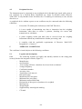
(UK/0126/0084) MI-006 United Kingdom of Great Britain and Northern Ireland Certificate of EC type-examination of a measuring instrument Number: UK/0126/0084 issued by the Secretary of State for Business, Innovation & Skills Notified Body Number 0126 In accordance with the requirements of the Measuring Instruments (Belt Weighers) Regulations 2006 (SI 2006/1259) which implement, in the United Kingdom, Council Directive 2004/22/EC, this certificate of EC type-examination has been issued to: Control Systems Technology Pty Ltd Unit 9 / 41-45 Lorraine Street Peakhurst NSW 2210 Australia in respect of continuous totalising automatic weighing instrument (belt weigher), designated the IPC-14, as described in the descriptive annex and having the following characteristics: Qmax Qmin dt Σmin ≤ > ≥ ≥ ≥ ≥ Belt speed Accuracy class ≥ dependent upon application 20 % Qmax 0.001 t 800 d for class 0.5 400 d for class 1 200 d for class 2 0.1 m/s to 15.0 m/s 0.5 The necessary data (principal characteristics, alterations, securing, functioning etc) for identification purposes and conditions (when applicable) are set out in the descriptive annex to this certificate. Signatory: for Date: 19 July 2010 Valid Until: 18 July 2020 Reference No: T1147/0006 P R Dixon Chief Executive National Weights & Measures Laboratory (Part of National Measurement office) Department for Business, Innovation & Skills Stanton Avenue Teddington Middlesex TW11 0JZ United Kingdom Descriptive Annex 1 INTRODUCTION This pattern of an automatic continuous totaliser (belt weigher), designed to weigh large quantities of loose material from bulk to bulk, is designated the IPC-14. It comprises: − − − a weighing platform a speed sensor an integrator type IPC-14 2 FUNCTIONAL DESCRIPTION 2.1 Mechanical 2.1.1 Weighing platform The weighing platform is designed to react only to forces perpendicular to the line of the conveyor belt. It consists of a fixed support frame (static) and a live frame (dynamic) and may include a ramp section bridging the static and dynamic parts. The static frame is the main support between the conveyor stringers which in turn supports the dynamic frame including the pair(s) of load cells. The dynamic frame supports the scale idlers and transfers the weight of the material to the load cells. As the material travels along the conveyor belt, a force is exerted through the suspended idlers to the dynamic frame. The movement in the load cell is sensed by its strain gauges when excited by voltage from the electronic integrator and produces a signal proportional to weight, which is returned to the integrator. 2.1.2 Load cells Any compatible load cell(s) may be used providing the following conditions are met: − There is a respective OIML Certificate of Conformity (R60) or a test certificate (EN45501) issued for the load cell by a Notified Body responsible for type examination under Directive 2009/23/EC. − The certificate contains the load cell types and the necessary load cell data required for the manufacturer’s declaration of compatibility of modules (WELMEC 2, Issue 5, May 2009, No 11), and any particular installation requirements. A load cell marked NH is allowed only if humidity testing to EN45501 has been conducted on this load cell. − The compatibility of the load cells and indicator is established by the manufacturer by means of the compatibility of modules calculation, contained in the above WELMEC 2 document, at the time of verification or declaration of EC conformity of type. − The load cell transmission must conform to one of the examples shown in the WELMEC Guide 2.4, “Guide for Load cells”. 2/9 2.1.2 Belt Displacement Transducer The conveyor belt displacement transducer may be shaft driven from a suitable pulley or may involve tags affixed to the end of a pulley instrumented to send pulses, each representing a precise amount of belt travel to the integrator. A fixed number of pulses are generated for each rotation of the pulley. The displacement transducer must be applied in a manner which ensures that slipping does not occur. It shall be driven from the clean side of the conveyor belt. It shall not be attached to a driven pulley of the conveyor belt. A dual redundant displacement transducer with automatic fail-over may be used. 2.2 Electrical 2.2.1 IPC-14 integrator The IPC-14 integrator (Figure 1) is the user interface and data handling terminal. It comprises a keypad with 16 keys, a back-lit LCD display with 4 lines of 40 characters and a circuit board with CPU. The load and belt displacement (travel) signals from the weighing platform and speed sensor are processed to derive rate of material flow and totalisation. The primary values of speed and load are available on a diagnostic display while primary derived values of rate and total are available on the main display. The display is checked at power-on, however, characters are a 5x7 dot matrix and any display faults are self evident. The integrator is protected by a metallic enclosure with lockable front door, according to drawing 0979902 rev B (Figure 2). The integrator is mains-operated and supplies the nominal 10 VDC needed to excite the load cells. The displacement transducer (tachometer / speed sensor) is powered from the integrator. The integrator is fitted with a non-volatile memory (FRAM) in which all parameters affecting the metrological characteristics of the instrument are stored, the FRAM memory retains the data indefinitely without the need for battery backup. The integrator is also fitted with a 3V Lithium battery to backup up volatile dynamic data such as the totaliser figures. The Integrator is powered from a built in float charged Battery Backed power supply which allows the integrator to be powered up by the push of a button for the purpose of viewing the totaliser figure in the event of a power outage. 2.5 Devices 2.5.1 The instrument is provided with the following devices: − − − − − − − General totalisation device (non-resettable, 10-digit) Main totalisation device (resettable, 8-digit) Semi-automatic zero-setting device (≤ ±2% Max), over a whole number of belt revolution Automatic zero-setting device (also known as Zero Tracking which operates over a whole number of belt revolution, ≤ ±2% Max), fitted with interlock preventing zero-setting while it is possible for material to feed onto the belt Indication of the flow rate (Q) Indication of the belt speed Error messages and alarms 3/9 2.6 Operation 2.6.1 Zero and Span calibrations are only available to authorised personnel, requiring password-protected Access Level greater than 0 and access to the sealed calibration/setup switch inside the console. These calibrations as well as “NTEP zero” (Semi-automatic zero executed in level 3 access) and “Initial span” (Menu (3)BeltScale/Calibrate/Span) may need to be performed depending upon operational needs. A “semi-auto zero” ((3)BeltScale/Calibrate/Zero) can be performed by an end user using the keypad, and is to be used to maintain the accuracy of the system as required. 2.6.2 Access levels greater than 0 are password-protected and used to define the operation of the system. They can only be accessed via the calibration/setup switch by authorised personnel. They allow viewing and editing the parameters to suit the application. The Access Level 0 is the only mode accessible to the end user and allows running totalisations while displaying rate and total weight. The keypad also allows the end user to view, but not edit, the system’s parameters. 2.6.3 The totaliser is continuously updated and displayed and is also logged in a built in history record space along with the information needed to identify the measurement. The system is fitted with alarms (out of range flow-rate or speed, power failure) to ensure accurate totalisation results. Error messages are displayed when the alarms are set and must be acknowledged by the user, the error message “the totalisation may not be accurate” also appear in the datalog when a critical alarm is detected. Each time there is a power outage this is considered to be a critical alarm and the “totalisation may not be accurate” alarm is displayed. 2.6.4 When the memory is full, measurement data is automatically overwritten, provided it is older than x days, with x fixed by parameter 658, which is protected by the calibration and setup switch. If the memory is full and all records are not old enough to be overwritten (parameter 658 and memory size should be chosen for each application so that this situation does not occur), the conveyor should stop and an error message is displayed on the controller. The totaliser can continue to operate and can be read when the alarm is cleared, the alarm should be recorded along with “Totaliser logging records have been lost” when memory space is freed and recording resumes. 2.6.5 An error message is displayed and must be acknowledged whenever a significant fault occurs, with this information recorded in the fault log. The measurement data also shows “Significant fault, weighing result may not be accurate”. 3 TECHNICAL DATA 3.1 The instrument has the following technical characteristics: Power supply 110 Vac, 50/60 Hz 240 Vac, 50/60 Hz ≥ 0.001 t Dependent upon application ≥ 20% Qmax ≥ 800 d for class 0.5 ≥ 400 d for class 1 ≥ 200 d for class 2 Totalisation scale interval Qmax Qmin Σmin 4/9 Operating speed Weigh length Load cells excitation voltage Minimum load cell impedance Maximum load cell impedance Minimum dead load voltage Measuring range minimum voltage (at max capacity) Measuring range maximum voltage (at max capacity) Climatic environment Electromagnetic environment Accuracy class Load cell cable 3.2 0.1 to 15 m/s Dependent upon application 10 Vdc 43.75 Ω 1100 Ω 2 mV 3 mV 50 mV -20 °C to 55 °C, Condensing (open) E1 and E2 ≥ 0.5 6 wire and screen (controller to junction box), then 4 wire and screen Documentation and drawings Description IPC-14 Installation Manual User/Service Manual Dimensional drawing Assembly drawing Parts list Electrical schematics Block diagram Main PCB circuit diagram 3.3 Document / Drawing No. 02500470 02500760 88500571 88500571 88500571 88500580 8850905 88500600 Software 3.3.1 The software is held in the EPROM and its version number is 092316xx.tsk, where 092316 is fixed for the legally relevant part and xx is for minor updates (xx must be greater than 75). The software version number can be accessed from the (1)Info menu then (2)Equipment. 3.3.2 Software download and configuration parameters are protected by a calibration & set-up switch located inside the controller enclosure, which can only be accessed with breaking the tamper-evident seal (see 6.2). 4 PERIPHERAL DEVICES AND INTERFACES 4.1 Interfaces − − − − − Load cell connection Speed sensor RS232/485 Digital I/O Analogue I/O 5/9 4.2 Peripheral devices The instrument may be connected to any peripheral device that has been issued with a parts or test certificate by a Notified Body responsible for Annex B (MI-006) under Directive 2004/22/EC in any Member State and bears the CE marking of conformity to the relevant directives; or A peripheral device without a parts or test certificate may be connected under the following conditions: − it bears the CE marking for conformity to the EMC Directive; − it is not capable of transmitting any data or instruction into the weighing instrument, other than to release a printout, checking for correct data transmission or validation; − it prints weighing results and other data as received from the weighing instrument without any modification or further processing; and − it complies with the applicable requirements of Directive 2004/22/EC Paragraph 8.1 of Annex I. 5 APPROVAL CONDITIONS The certificate is issued subject to the following conditions: 5.1 Legends and inscriptions 5.1.1 The following legends are legibly and durably marked on the rating plate securely fixed to the integrator console (Figure 3): − − − − − − − − − − − − − − − − Manufacturer Serial number ”Zero setting will have a duration of at least # belt revolutions” Voltage/frequency Certification number Accuracy class Totalisation scale interval Belt speed range Maximum flow rate Qmax Minimum flow rate Qmin Minimum totalised load Σmin Designation of the type(s) of product to be weighed Max capacity Weigh length Supplementary metrological marking CE-mark 6/9 6 LOCATION OF SEALS AND VERIFICATION MARKS 6.1 The “CE” marking, supplementary metrology marking and certificate number are located on the rating plate bracket which is fixed to the side of the integrator console. The CE mark shall be impossible to remove without damaging it. The rating plate shall be impossible to remove without it being destroyed. The markings and inscriptions shall fulfil the requirements of Paragraph 9 of Annex I of the Directive 2004/22/EC. 6.2 Components that may not be dismantled or adjusted by the user (calibration and setup switch, load cell junction box, EPROM) must be secured by either a wire and seal or a tamper evident label and securing mark: The securing mark may be either: − − 7 a mark of the manufacturer and/or manufacturer’s representative, or an official mark of a verification officer. ALTERNATIVES There are currently no alternatives. 8 ILLUSTRATIONS Figure 1 Figure 2 Figure 3 IPC-14 integrator Enclosure Rating plate (typical example) 9 CERTIFICATE HISTORY ISSUE NO. DATE DESCRIPTION UK/0126/0084 19 July 2010 Type examination certificate first issued. - - No revisions have been issued. 7/9 Figure 1 IPC-14 integrator Figure 2 Enclosure 8/9 Figure 3 Rating plate (typical example) Crown Copyright 2010 NATIONAL WEIGHTS AND MEASURES LABORATORY (Part of National Measurement Office) Department for Business, Innovation & Skills 9/9