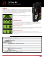
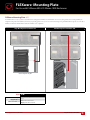
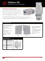
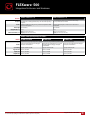
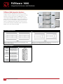
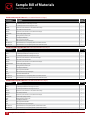
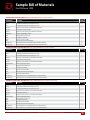
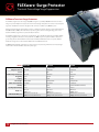
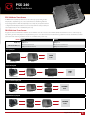
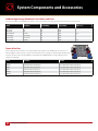
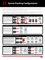
1
Product guide 8 inverter/chargers charge controllers Communications integrated systems Energy Storage OutBack Power Technologies Member of The Alpha Group Masters of the Off-Grid™… OutBack Power Technologies is the leading designer and manufacturer of advanced power conversion components and systems for renewable energy, backup, and mobile applications. From Baja to Bangladesh, from the Equator to the poles, OutBack components transform energy from renewable and conventional sources into the clean, reliable power that people need to transform the quality of their lives. First Choice for the New Grid… Identified by Pike Research as “far and away the leading vendor in the remote microgrid market*,” OutBack’s leadership across all segments is rooted in the brand’s reputation for extreme reliability and dedication to technical innovation. The products here continue that tradition of excellence while bringing OutBack’s legendary off-grid technology and performance to an even wider range of energy production and power management applications. A privately held company headquartered in Arlington, WA, OutBack Power is also a member of The Alpha Group—a global alliance of independent companies that share a common philosophy: create world-class powering solutions for communication, commercial, industrial and renewable energy markets. OutBack has pioneered many of the technologies that have become industry standards for power conversion technology, and there’s more to come. 2 *Remote Microgrids: Market Analysis and Forecasts, 2012. Table of Contents Inverter/Chargers Integration Enclosures and Hardware Radian Series............................................................................ 8-11 FLEXware ICS................................................................................ 62 FX/VFX Series........................................................................ 12-16 FLEXware ICS Plus..................................................................... 63 GTFX/GVFX Series............................................................... 18-21 FLEXware PV Combiner Box Series................................. 64 Specialized Application Models................................ 22-27 Mounting Plates......................................................................... 65 Charge Controllers FLEXware 250........................................................................ 66-67 FLEXware 500........................................................................ 68-69 FLEXmax Series.................................................................... 30-31 FLEXware 1000..................................................................... 70-71 FLEXmax Extreme............................................................... 32-33 Sample Bill of Materials................................................... 72-73 Communications OPTICS RE....................................................................................... 36 MATE3, MATE and MATE2.............................................. 37-38 FLEXware Surge Protector................................................... 74 PSX-240............................................................................................ 75 AXS Port........................................................................................... 39 System Components, Accessories and Stacking Configurations HUB4 and HUB10.3................................................................... 40 Panel Mount Breakers............................................................. 78 FLEXnet DC.................................................................................... 41 DIN Breakers.................................................................................. 78 Integrated Systems FLEXpower ONE......................................................................... 44 FLEXpower TWO........................................................................ 45 FLEXpower THREE..................................................................... 46 FLEXpower FOUR...................................................................... 47 FLEXcoupled Packages................................................... 48-49 Energy Storage EnergyCell Batteries.......................................................... 53-56 Enclosures and Racks....................................................... 57-59 PV Ground-Fault Detection and Interruption.......... 79 DC Bus Bars.................................................................................... 79 DC Current Shunts.................................................................... 79 Conduit Adapters...................................................................... 80 Mounting Brackets................................................................... 80 DIN Rail End Clamp.................................................................. 80 DC Cable Assemblies.............................................................. 81 DC DIN Mount Breakers......................................................... 81 High Voltage DIN Mount Fuse Holders and Fuses........ 82 Terminal Bus Bars....................................................................... 82 System Stacking Configurations...................................... 83 3 Inverter/Chargers Radian Series Introduction and Specifications..................................................................................... 8-9 GS Load Center............................................................................................................................ 10 Sample Bill of Materials and Optional Accessories............................................... 11 FX/VFX Series Introduction.................................................................................................................................. 12 60Hz/120V...................................................................................................................................... 13 60Hz/230V...................................................................................................................................... 14 J-Series 50Hz/120V.................................................................................................................... 15 50Hz/230V...................................................................................................................................... 16 GTFX/GVFX Series Introduction.................................................................................................................................. 18 60Hz/120V...................................................................................................................................... 19 60Hz/127V...................................................................................................................................... 20 50Hz/230V...................................................................................................................................... 21 Specialized Application Models M-Series 60Hz/120V................................................................................................................. 22 M-Series 50Hz/230V................................................................................................................. 23 OBX Extreme Series 60Hz/120V........................................................................................ 24 OBX Extreme Series 50Hz/230V........................................................................................ 25 GFX International Series 60Hz/120V.............................................................................. 26 GFX International Series 50Hz/230V.............................................................................. 27 OutBack reserves the right to make changes to the products and information contained in this document without notice. Copyright © 2015 OutBack Power Technologies. All Rights Reserved. Inverter/Chargers 7 Radian Series ™ Inverter/Charger With all the hallmark features you’ve come to expect from the Radian Series inverter/charger, the expanded Radian family includes four models, seven operating modes and two advanced new technologies designed to meet the unique requirements of the world’s different regions. Each new model offers seven operating modes and two advanced, future-ready technologies, including GridZero technology. GridZero technology, the newest of the Radian’s seven input modes, provides the perfect balance between utility power and stored renewable energy. By allowing a home or business to satisfy most of its power needs with renewable sources grid supplied power is only tapped when load demand exceeds a pre-set threshold. While the Radian is still gridconnected, grid dependence can be reduced to zero whenever possible. All of this means the Radian offers unmatched performance, reliability, value and system flexibility today and into the future. Product Highlights: Grid-Interactive and Standalone Power Systems GridZero Technology Minimizes Grid Dependence* Various Frequency, Voltage and Phase Options Multiple Output Power Options Stackable and Scalable Radian Series w/GSLC High Performance, Pure Aesthetics High-End Residential OutBack Grid/Hybrid System, Ozark Mountains, MO Skywire Electrical Systems is a system integrator offering their commercial and residential clients everything from lighting design to solar electricity and thermal systems. As is typical of installers taking a custom, craftsman like approach, referrals from satisfied customers drive the business—and it was a grid-tied system installed in a residence that inspired a neighboring one to go all-out with energy independence, something highly desirable in a rugged mountain environment. As always, Skywire responded with its best efforts, which included multiple OutBack Power Radian Series inverter/chargers and other OutBack components in a 24kW PV/solar system. Augmented by a 27kW generator, the complete system can power the residence through any outage or emergency. A key to selling such a comprehensive system was the OutBack brand itself. Notes Skywire owner James Bartley, “Our customers are impressed with the results, and OutBack’s strong reputation in the industry gives them additional assurance as they transition to solar power.” 8 Inverter/Chargers *This does not apply to the GS8048. Radian Series ™ Inverter/Charger Specifications Domestic (For Selected North, Central and Latin American Countries) Models: GS8048 Nominal DC Input Voltage Continuous Output Power (@ 25°C) AC Output Voltage (Selectable) AC Output Frequency (Selectable) Continuous AC Output Current (@ 25°C) Idle Consumption (Invert Mode, No Load) Typical Efficiency CEC Weighted Efficiency Total Harmonic Distortion Output Voltage Regulation Maximum Output Current Overload Capacity AC Input Voltage Range (Adjustable) AC Input Frequency Range (Default) Grid-Interactive Voltage Range (Default) Grid-Interactive Frequency Range Maximum AC Input Current Maximum Utility Interactive Current Continuous Battery Charge Output DC Input Voltage Range Temperature Range (Power derated above 25°C) Accessory Ports Non-Volatile Memory Field Upgradable Firmware Chassis Type Certifications Warranty Weight (lb/kg) Dimensions H x W x D (in/cm) International (For Europe, Asia and Global Countries) GS8048A GS4048A GS7048E GS3548E 48VDC 48VDC 48VDC 48VDC 48VDC 8000VA 8000VA 4000VA 7000VA 3500VA 120/240VAC 120/240VAC (200-260VAC) 120/240VAC (200-260VAC) 230VAC (210-250VAC) 230VAC (210-250VAC) 60Hz 60Hz (50Hz) 60Hz (50Hz) 50Hz (60Hz) 50Hz (60Hz) 33.3AAC @ 240VAC 33.3AAC @ 240VAC 16.7AAC 30AAC 15.2AAC 30W 34W 34W 34W 34W 93% 93% 93% 92% 92% 90% 92.5% 92.5% — — Max. Total Harmonic: <5%, Max. Single Voltage Harmonic: <2% Max. Total Harmonic: <5%, Max. Single Voltage Harmonic: <2% ±2% ±2% ±2% ±2% ±2% 1ms Peak: 100AAC @ 240VAC, 200AAC @ 120VAC 100ms RMS: 70.7AAC @ 240VAC 1ms Peak: 100AAC @ 240VAC, 200AAC @ 120VAC 100ms RMS: 70.7AAC @ 240VAC 1ms Peak: 50AAC @ 240VAC 100ms RMS: 35.35AAC @ 240VAC 1ms Peak: 100AAC 100ms RMS: 70.7AAC 1ms Peak: 50AAC 100ms RMS: 35.35AAC 100ms Surge: 16.97kVA 5 Seconds: 12.0kVA 30 Minutes: 9.0kVA 100ms Surge: 16.97kVA 5 Seconds: 12.0kVA 30 Minutes: 9.0kVA 100ms Surge: 8.5kVA 5 Seconds: 6.0kVA 30 Minutes: 4.5kVA 100ms Surge: 16.3kVA 5 Seconds: 11.5kVA 30 Minutes: 7.9kVA 100ms Surge: 8.2kVA 5 Seconds: 5.8kVA 30 Minutes: 4.0kVA (L1-N or L2-N) 70 to 140VAC (L1-N or L2-N) 85 to 140VAC (L1-N or L2-N) 85 to 140VAC (L-N) 170 to 290VAC (L-N) 170 to 290VAC 54 to 66Hz @ 60Hz 54 to 66Hz @ 60Hz (45 to 55Hz @ 50Hz) (L1-N or L2-N) 106 to 132VAC (L1-N or L2-N) 108 to 132VAC (L1-N or L2-N) 108 to 132VAC (L-N) 208 to 252VAC (L-N) 208 to 252VAC 59.3 to 60.5Hz 59.3 to 60.5Hz 59.3 to 60.5Hz 57.0 to 61.0Hz 57.0 to 61.0Hz 50AAC @ 240VAC 50AAC @ 240VAC 50AAC @ 240VAC 50AAC 50AAC 32A 30A 15A 30A 15A 115.0ADC 115.0ADC 57.5ADC 100.0ADC 50.0ADC 40 to 64VDC 40 to 64VDC 40 to 64VDC 40 to 64VDC 40 to 64VDC Rated: 0 to 50°C Maximum:-25 to 60°C Rated: -20 to 50°C Maximum:-40 to 60°C Rated: -20 to 50°C Maximum:-40 to 60°C Rated: -20 to 50°C Maximum:-40 to 60°C Rated: -20 to 50°C Maximum:-40 to 60°C 45 to 55Hz @ 50Hz (54 to 66Hz @ 60Hz) Remote Temperature Sensor, MATE3 & HUB Communications Remote Temperature Sensor, MATE3 & HUB Communications Yes Yes Yes Yes Yes Yes Yes Yes Yes Yes Vented Vented Vented Vented Vented ETL Listed to UL1741, CSA C22.2 No. 107.1 ETL Listed to UL1741, CE, CSA C22.2 No.107.1, UL 1778 Annex F, IEC 62109-1 ETL, RoHS compliant per directive 2011/65/EU, FCC Class B, IEEE 1547.1, EN61000-6-1, EN61000-6-3, EN61000-3-2, EN61000-3-3 ETL Listed to UL1741, CE, CSA C22.2 No.107.1, UL 1778 Annex F, IEC 62109-1 ETL, RoHS compliant per directive 2011/65/EU, FCC Class B, IEEE 1547.1, EN61000-6-1, EN61000-6-3, EN61000-3-2, EN61000-3-3 IEC 62477-1, AS4777.2, AS477.3, EN61000-6-1, EN61000-6-3, EN61000-3-2, EN61000-3-3, AS3100, CE, RoHS compliant per directive 2011/65/EU IEC 62109-1, IEC 62477-1, AS4777.2, AS477.3, EN61000-6-1, EN610006-3, EN61000-3-2, EN61000-3-3, AS3100, CE, RoHS compliant per directive 2011/65/EU Standard 5 year, available 10 year Standard 5 year, available 10 year Standard 5 year, available 10 year Standard 5 year, available 10 year Standard 5 year, available 10 year Unit: 125 / 56.7 Shipping: 140 / 63.5 Unit: 125.0 / 56.7 Shipping: 140.0 / 63.5 Unit: 82.0 / 37.2 Shipping: 94.0 / 42.6 Unit: 125.0 / 56.7 Shipping: 140.0 / 63.5 Unit: 81.0 / 36.7 Shipping: 93.0 / 42.1 Unit: 28 x 16 x 8.7 / 71.1 x 40.6 x 22.1, Shipping: 34.5 x 21 x 14.5 / 87.6 x 53.3 x 36.8 Unit: 28 x 16 x 8.7 / 71.1 x 40.6 x 22.1, Shipping: 34.5 x 21 x 14.5 / 87.6 x 53.3 x 36.8 Breaker Configuration Diagram Breaker Panel (DC) Holds up to eighteen 0.75” (19 mm) wide breakers, two 1.5” (39 mm) wide breakers and one FLEXnet DC. Support for optional AC Input-Output-Bypass Assembly. AC breakers are rated from 10-60A of AC current. A new double-pole 50A breaker is available to support 120/240V input and loads. Breaker Panel Inverter/Chargers 9 Radian Series GSLC ™ GS Load Center (GSLC) Balance-of-System Enclosure Specifications Radian Series GS Load Center (GSLC) The GSLC is a balance-of-systems enclosure designed to seamlessly integrate with the Radian Series inverter/chargers, FLEXmax charge controllers, and OutBack HUB communications manager. Three available models allow quick and easy installation of power systems of any size. Additional features of the GSLC line include its powder-coated galvanized chassis, ample knockout locations fitting 1/2” to 2” conduit, aesthetic stainless steel door and simple mounting to a Radian Series inverter/charger. It is listed to UL1741 and CSA C22.2 No. 107.1-01, is Type 1 indoor rated (IP30) and can also be used on its own as a separate breaker enclosure for use with other inverter models. GSLC Knockout Location Diagram Left Side • (1) ½” knockout (0.875” diameter) • (7) 1” knockout (1.375” diameter) • (2) 2” knockout (2.468” diameter) Right Side • (1) ½” knockout (0.875” diameter) • (4) 1” knockout (1.375” diameter) • (2) 2” knockout (2.468” diameter) Back Side • (1) 2” knockout (2.468” diameter) Bottom Side Top Side* • (2) ½” knockout (0.875” diameter) • (2) ¾” knockout (1.109” diameter) • (2) 1” knockout (1.375” diameter) • (2) 1¼” knockout (1.734” diameter) • (1) 1½” knockout (1.984” diameter) • (2) 2” knockout (2.468” diameter) • (2) 1” knockout (1.375” diameter) • (2) 2” knockout (2.468” diameter) GSLC Model Numbers Installed Components Enclosure w/ Hinged Door 175A Breakers Dual AC Inputs GFDI FLEXnet DC PV Disconnects 500A DC Shunt 120/240VAC Bypass 230VAC Bypass ROCB, 4-50A 120/240 Circuit Breakers, Sliding Bypass Interlock Weight (lb/kg) Recommended Radian Model 10 Inverter/Chargers GSLC GSLC175AC-120/240 GSLC175120/240 GSLC175-230 GSLC175PV-120/240 GSLC175PV-230 GSLC175PV1-120/240 GSLC175PV1-230 u u u u u u u u 2 2 2 2 2 1 1 u u u u u u u u u u u u u u u 2 2 1 1 3 3 2 2 1 1 1 u u 1 u u u u u u Unit: 26 / 11.8 Shipping: 34 / 15.4 Unit: 40 / 18.1** Shipping: 45 / 20.4 Unit: 37 / 16.8 Shipping: 45 / 20.4 Unit: 37 / 16.8 Shipping: 45 / 20.4 Unit: 40 / 18.1** Shipping: 45 / 20.4 Unit: 40 / 18.1** Shipping: 45 / 20.4 Unit: 40 / 18.1** Shipping: 45 / 20.4 Unit: 40 / 18.1** Shipping: 45 / 20.4 GS8048 GS8048A GS4048A GS7035E GS3548E GS8048 GS8048A GS4048A GS8048 GS8048A GS4048A GS7048E GS8048 GS8048A GS7048E GS4048A GS3548E *Not to be used with Radian Series inverter/charger. **Minimum Radian Series ™ Sample Bill of Materials and Optional Accessories Radian Series GSLC Sample Bill of Materials (w/Radian Series inverter/charger and dual FLEXmax charge controllers): Part Number Description Quantity GS8048A inverter/charger 8000W 120/240VAC grid-interactive and standalone solution with dual AC inputs 1 GSLC175-PV-120/240 Pre-wired GSLC with 175A inverter disconnects, GFDI and PV disconnects for two charge controllers, FLEXnet DC with 3 shunts, 120/240VAC inverter bypass and dual AC inputs 1 FLEXmax FM80-150VDC 80A output @ 40°C, 12 to 60VDC battery, 150VDC PV maximum 2 MATE3 Universal version, light gray square housing with Ethernet port 1 HUB4 Four port, up to 4 devices and one MATE 1 FW-MB3 Bracket for mounting a MATE3 system display on the side of Radian Series inverter/charger, GSLC, FW500 and FW1000 DC enclosures 1 FW-CCB2 Mounting bracket for two side mounted charge controllers on GSLC, FW500 and FW1000 DC enclosures 1 Radian Series GSLC Sample Bill of Materials (w/dual Radian Series inverter/chargers for UPS or AC only applications): Part Number Description Quantity GS8048A inverter/charger 8000W 120/240VAC grid-interactive and standalone solution with dual AC inputs 2 GSLC GS load center for Radian Series inverter/charger, includes inverter bus bars, ground bus bar, 500ADC shunt assembly with negative TBB, neutral TBB and two STBB-RED bus bars. 2 PNL-175-DC 175A, 125VDC, 3/8” stud terminals 4 PNL-50D-AC-120/240 50A 120/240VAC Double Panel - Mount Breaker 6 MATE3 Universal version, light gray square housing with Ethernet port 1 HUB4 Four Port, up to 4 devices and one MATE 1 FW-MB3 Bracket for mounting a MATE3 system display on the side of Radian Series inverter/charger, GSLC, FW500 and FW1000 DC enclosures 1 FN-DC FLEXnet DC monitors up to 3 shunts for improved battery management 1 Accessories Part Number Description/Details GS-SBUS Shunt bus to connect three shunts together within the GSLC STBB-BLACK Bus bar with black insulators and mounting screws STBB-RED Bus bar with red insulators and mounting screws STBB-WHITE Bus bar with white insulators and mounting screws PNL-50D-AC-120/240 Current rating: 50A (each of 2 poles), Voltage rating: 120/240VAC, Branch circuit: 5k AIC, Terminals: 1/4” stud, Width: 1.5” (39mm) GS-IOB-120/240VAC Input-Output Bypass Assembly Description: Field-installable kit for bypassing the AC input to the AC output for inverter maintenance or installation. Also provides overcurrent protection. Intended for use with single inverter installations. Includes: Four 50A 120/240VAC dual pole panel mount breakers, sliding bypass interlock plate, three STBB-BLACK and three STBB-RED terminal bus bars, wire and hardware kit. System rating: 120/240VAC @ 50A, Bypass breaker: Dual pole @ 50A, Input breakers: 175A, 2/0 AWG DC cable 15 inches (38 cm) long with ring terminals, Output Breaker: Dual pole @ 50A Inverter/Chargers 11 FX/VFX Series Off-Grid Sealed and Vented Inverter/Chargers 2 1 Sealed 3 Vented Pure Sinewave Technology The appliances and electronics in a home or business need a clean, undistorted AC sinewave signal to operate properly. OutBack inverter/ chargers use proprietary digital switching technology coupled to the custom, low-loss/high-efficiency transformer to deliver sinewave AC power that’s actually cleaner than the electricity many utility companies can generate. Internal Components To achieve a whole that’s greater than the sum of its parts, OutBack starts with inverter parts that meet or exceed the highest standards in place in their respective categories. Components are high-temperature rated to ensure exceptionally long operational life, and all critical assemblies are custom-built, right down to busbars and terminals. The all-critical transformer is a completely custom design, made with high-grade steel laminates and engineered for low-loss and high-efficiency operation. The transformer’s base and framework incorporate a unique architecture to transfer or “wick” heat from the transformer directly to the inverter’s chassis, enabling extra-high output and increasing reliability. 1 On-Board Intelligence An OutBack inverter/charger can sense power outages, surges, or anything else affecting your service—and takes immediate steps to provide a backup (including starting a generator). It even has a standby/sleep mode to conserve power, waking up when lights or appliances require power, for example. An OutBack inverter/charger can protect itself from potential faults including an AC short and low/ high battery voltage. OutBack inverter/chargers have superior surge capabilities and smarter battery charging algorithms—and almost all settings are user-adjustable for complete application customization. 2 Heat Management Power-conversion means heat production. So the better an inverter manages heat, the more power it can produce. Typical inverters have to be vented in order to be adequately cooled. OutBack’s sealed inverter design is behind a reputation that goes way beyond “adequate” and “typical,” with an innovative internal forced-convection method to keep the inverter’s temperature range optimal while keeping out dust, dirt and moisture. OutBack’s vented inverters use similar thermal management technology to achieve industry-leading output for their size. 3 Inverter Chassis Everything is housed in OutBack’s distinctive cast-aluminum powdercoated chassis for a purely functional reason. Because cast aluminum can’t bend or deform, it is ideal for protecting internal components and ensuring the mechanical precision necessary to maintain the tolerances and alignment an ultra-high quality sealed inverter demands. As with a high-performance engine block, OutBack’s cast-aluminum frame is also superior at dissipating heat, and is a component of the inverter’s advanced thermal management system. 12 Inverter/Chargers FX/VFX Off-Grid 60Hz/120V Inverter/Chargers Sealed Models Models: FX2012T Nominal DC Input Voltage Continuous Power Rating (@ 25°C) AC Frequency/Voltage Continuous AC RMS Output (@25°C) Idle Power Typical Efficiency Total Harmonic Distortion Output Voltage Regulation Maximum Output Current AC Overload Capacity AC Input Current Maximum AC Input Voltage Range (MATE Adjustable) AC Input Frequency Range DC Input Voltage Range Continuous Battery Charger Output Temperature Range Certifications Warranty Weight (lb/kg) Dimensions H x W x L (in/cm) Vented Models FX2524T FX3048T VFX2812 VFX3524 VFX3648 12VDC 24VDC 48VDC 12VDC 24VDC 48VDC 2000VA 2500VA 3000VA 2800VA 3500VA 3600VA 60Hz / 120VAC 60Hz / 120VAC 60Hz / 120VAC 60Hz / 120VAC 60Hz / 120VAC 60Hz / 120VAC 17AAC 20.8AAC 25AAC 23.3AAC 29.2AAC 30AAC Full: ~20W Search: ~6W Full: ~23W Search: ~6W Full: ~23W Search: ~6W Full: ~20W Search: ~6W Full: ~20W Search: ~6W Full: 23W Search: ~6W 90% 93% 93% 90% 92% 93% Typical: 2% Maximum: 5% Typical: 2% Maximum: 5% Typical: 2% Maximum: 5% Typical: 2% Maximum: 5% Typical: 2% Maximum: 5% Typical: 2% Maximum: 5% ±2% ±2% ±2% ±2% ±2% ±2% Peak: 56AAC RMS: 40AAC Peak: 70AAC RMS: 50AAC Peak: 70AAC RMS: 50AAC Peak: 56AAC RMS: 40AAC Peak: 70AAC RMS: 50AAC Peak: 70AAC RMS: 50AAC Surge: 4800VA 5 Seconds: 4000VA 30 Minutes: 2500VA Surge: 6000VA 5 Seconds: 4800VA 30 Minutes: 3200VA Surge: 6000VA 5 Seconds: 4800VA 30 Minutes: 3200VA Surge: 4800VA 5 Seconds: 4000VA 30 Minutes: 3200VA Surge: 6000VA 5 Seconds: 5000VA 30 Minutes: 4000VA Surge: 6000VA 5 Seconds: 5000VA 30 Minutes: 4000VA 60AAC 60AAC 60AAC 60AAC 60AAC 60AAC 80 to 150VAC 80 to 150VAC 80 to 150VAC 80 to 150VAC 80 to 150VAC 80 to 150VAC 55 to 65Hz 55 to 65Hz 55 to 65Hz 54 to 66Hz 54 to 66Hz 54 to 66Hz 10.5 to 17VDC 21 to 34VDC 42 to 68VDC 10.5 to 17VDC 21 to 34VDC 42 to 68VDC 80ADC 55ADC 35ADC 125ADC 82ADC 45ADC Rated: 0 to 50°C (power derated above 25°C) Maximum*: -25 to 60°C Rated: 0 to 50°C (power derated above 25°C) Maximum*: -25 to 60°C ETL Listed to UL1741 ETL Listed to UL1741 Standard 5 year Standard 5 year Unit: 62 / 29 Shipping: 67 / 31 Unit: 61 / 28 Shipping: 67 / 31 Unit: 13 x 8.25 x 16.25 / 33 x 21 x 41 Shipping: 21.75 x 13 x 22 / 55 x 33 x 56 Unit: 12 x 8.25 x 16.25 / 30.5 x 21 x 41 Shipping: 21.75 x 13 x 22 / 55 x 33 x 56 Powering Change in Paradise Mini-Grid Powering the Community of Melano, Borneo A fishing and pepper-farming village at the tip of East Malaysia, Melano is exceptionally isolated—unreachable by land, and accessible only after a long road-trip followed by an even longer boat trip. With both population and economic growth in place, Melano has reached the point where its homes, police station, community library and religious facilities are primed for modern conveniences and appliances powered by electricity. That’s part of the reason why it was selected for the evaluation of a planned roll-out of mini-grid electrical systems what will ultimately serve similar communities throughout Malaysia. For this pioneering effort, (2) OutBack FLEXpower systems were selected to run the 18.4kW mini-grid installation. High output from a relatively compact size made FLEXpower an ideal choice in a place where every component must be brought in by small boat and hand-carried to the installation site on poles, and where reliability is paramount because a replacement is literally a voyage away. As the Smart Grid Observer** noted when citing a recent Pike Research report on remote micro-grids, “ in the village power systems sub-segment, OutBack Power, which offers customized inverters and load controls optimized for rugged remote applications, is far and away the leading vendor.” *Functions, but does not necessarily meet all component specifications. **June 15, 2012, “Remote Micro-Grids Poised for Growth” Inverter/Chargers 13 FX/VFX Off-Grid 60Hz/230V Inverter/Chargers Sealed Models Models: FX2024WT Nominal DC Input Voltage Continuous Power Rating (@ 25°C) AC Frequency/Voltage Continuous AC RMS Output (@25°C) Idle Power Typical Efficiency Total Harmonic Distortion Output Voltage Regulation Maximum Output Current AC Overload Capacity AC Input Current Maximum AC Input Voltage Range (MATE Adjustable) AC Input Frequency Range DC Input Voltage Range Continuous Battery Charger Output Temperature Range Warranty Weight (lb/kg) Dimensions H x W x L (in/cm) Vented Models FX2348WT VFX3024W VFX3048W 24VDC 48VDC 24VDC 48VDC 2000VA 2300VA 3000VA 3000VA 60Hz / 230VAC 60Hz / 230VAC 60Hz / 230VAC 60Hz / 230VAC 8.7AAC 10AAC 13AAC 13AAC Full: ~20W Search: ~6W Full: ~23W Search: ~6W Full: ~20W Search: ~6W Full: 20W Search: ~6W 92% 93% 92% 93% Typical: 2% Maximum: < 5% Typical: 2% Maximum: < 5% Typical: 2% Maximum: < 5% Typical: 2% Maximum: < 5% ±2% ±2% ±2% ±2% Peak: 35AAC RMS: 25AAC Peak: 35AAC RMS: 25AAC Peak: 35AAC RMS: 25AAC Peak: 35AAC RMS: 25AAC Surge: 5750VA 5 Seconds: 4800VA 30 Minutes: 3100VA Surge: 5750VA 5 Seconds: 4800VA 30 Minutes: 3100VA Surge: 5750VA 5 Seconds: 4800VA 30 Minutes: 3100VA Surge: 5750VA 5 Seconds: 4800VA 30 Minutes: 3100VA 30AAC 30AAC 30AAC 30AAC 160 to 300VAC 160 to 300VAC 160 to 300VAC 160 to 300VAC 54 to 66Hz 54 to 66Hz 54 to 66Hz 54 to 66Hz 21 to 34VDC 42 to 68VDC 21 to 34VDC 42 to 68VDC 55ADC 35ADC 85ADC 45ADC Rated: 0 to 50°C (power derated above 25°C) Maximum*: -25 to 60°C Rated: 0 to 50°C (power derated above 25°C) Maximum*: -25 to 60°C Standard 5 year Standard 5 year Unit: 62 / 29 Shipping: 67 / 31 Unit: 61 / 28 Shipping: 67 / 31 Unit: 13 x 8.25 x 16.25 / 33 x 21 x 41 Shipping: 21.75 x 13 x 22 / 55 x 33 x 56 Unit: 12 x 8.25 x 16.25 / 30.5 x 21 x 41 Shipping: 21.75 x 13 x 22 / 55 x 33 x 56 Scaling New Heights in Power Generation Rifugio Alimonta Climbing Lodge in the Italian Alps The Dolomites have been a destination of world-class mountaineers for centuries. Its iconic peaks draw climbers and hikers from around the world, attracted by both the beauty and the challenge. The Rifugio (refuge) Alimonta was conceived and built to be their home away from home while exploring the peaks: a combination base, lodge and cafeteria at 8,464ft/2,580m altitude beautifully integrated into its magnificent surroundings. Of course, being several kilometers higher than the closest electrical grid means that off-grid operation is a given—and with “next day air” wishful thinking, the choice of off-grid system components was driven by which brand could provide the ultimate balance between reliability and performance. Based on that criteria, the choice of off-grid power components for this installation came down to a field of one: OutBack. After all, for anyone or anything representing a peak of excellence the old saying holds true: it’s always lonely at the top. 14 Inverter/Chargers *Functions, but does not necessarily meet all component specifications. J-Series FX/VFX Off-Grid 50Hz/120V Inverter/Chargers for Jamaica and Other Markets Sealed Model Models: FX2024JT Nominal DC Input Voltage Continuous Power Rating (@ 25°C) AC Frequency/Voltage Continuous AC RMS Output (@25°C) Idle Power Typical Efficiency Total Harmonic Distortion Output Voltage Regulation Maximum Output Current AC Overload Capacity AC Input Current Maximum AC Input Voltage Range (MATE Adjustable) AC Input Frequency Range DC Input Voltage Range Continuous Battery Charger Output Temperature Range Warranty Weight (lb/kg) Dimensions H x W x L (in/cm) Vented Model VFX3024J 24VDC 24VDC 2000VA 3000VA 50Hz / 120VAC 50Hz / 120VAC 16.7AAC 25AAC Full: ~20W Search: ~6W Full: ~20W Search: ~6W 92% 92% Typical: 2% Maximum: < 5% Typical: 2% Maximum: < 5% ±2% ±2% Peak: 70AAC RMS: 50AAC Peak: 70AAC RMS: 50AAC Surge: 6000VA 5 Seconds: 4800VA 30 Minutes: 3100VA Surge: 6000VA 5 Seconds: 4800VA 30 Minutes: 3100VA 60AAC 60AAC 80 to 150VAC 80 to 150VAC 44 to 56Hz 44 to 56Hz 21 to 34VDC 21 to 34VDC 55ADC 85ADC Rated: 0 to 50°C (power derated above 25°C) Maximum*: -25 to 60°C Rated: 0 to 50°C (power derated above 25°C) Maximum*: -25 to 60°C Standard 5 year Standard 5 year Unit: 62 / 29 Shipping: 67 / 31 Unit: 61 / 28 Shipping: 67 / 31 Unit: 13 x 8.25 x 16.25 / 33 x 21 x 41 Shipping: 21.75 x 13 x 22 / 55 x 33 x 56 Unit: 12 x 8.25 x 16.25 / 30.5 x 21 x 41 Shipping: 21.75 x 13 x 22 / 55 x 33 x 56 An Island of Productivity Former Sugar Plantation Converted into a Woodworking Facility, St. Kitts Island, West Indies Like almost everything else on an island, energy has to come from someplace else. Which makes electricity from island-based power utilities both very expensive and often intermittent. Focusing on emerging markets in remote locations, Solar Nexus International designs and installs customized renewable energy systems ideal for island-based customers. When one on St. Kitts wanted to covert an old plantation into a modern woodworking business, Solar Nexus needed something that could support high-powered electrical equipment day in and out while withstanding constant exposure to heat, salt air and high humidity—and also have the flexibility to draw on the grid only when needed and permit off-grid operation whenever possible. Their PV/solar solution was built around OutBack’s FLEXware 1000 platform with four inverter/chargers which can use the grid as a backup in HBX mode. The system’s capacity was so strong that the owner was later able to use it to power the entire property— a fact that didn’t surprise Solar Nexus CEO Eric Youngren, who said “for solar power in remote locations, OutBack is the best in the business.” *Functions, but does not necessarily meet all component specifications. Inverter/Chargers 15 FX/VFX Off-Grid 50Hz/230V Inverter/Chargers for Europe and International Markets Sealed Models Models: FX2012ET Nominal DC Input Voltage Continuous Power Rating (@ 25°C) AC Frequency/Voltage Continuous AC RMS Output (@25°C) Idle Power Typical Efficiency Total Harmonic Distortion Output Voltage Regulation Maximum Output Current AC Overload Capacity AC Input Current Maximum AC Input Voltage Range (MATE Adjustable) AC Input Frequency Range DC Input Voltage Range Continuous Battery Charger Output Temperature Range Warranty Weight (lb/kg) Dimensions H x W x L (in/cm) Vented Models FX2024ET FX2348ET VFX2612E VFX3024E VFX3048E 12VDC 24VDC 48VDC 12VDC 24VDC 48VDC 2000VA 2000VA 2300VA 2600VA 3000VA 3000VA 50Hz / 230VAC 50Hz / 230VAC 50Hz / 230VAC 50Hz / 230VAC 50Hz / 230VAC 50Hz / 230VAC 8.7AAC 8.7AAC 10AAC 11.3AAC 13AAC 13AAC Full: ~20W Search: ~6W Full: ~20W Search: ~6W Full: ~23W Search: ~6W Full: ~20W Search: ~6W Full: ~20W Search: ~6W Full: ~23W Search: ~6W 90% 92% 93% 90% 92% 93% Typical: 2% Maximum: 5% Typical: 2% Maximum: 5% Typical: 2% Maximum: 5% Typical: 2% Maximum: 5% Typical: 2% Maximum: 5% Typical: 2% Maximum: 5% ±2% ±2% ±2% ±2% ±2% ±2% Peak: 28AAC RMS: 20AAC Peak: 35AAC RMS: 25AAC Peak: 35AAC RMS: 25AAC Peak: 28AAC RMS: 20AAC Peak: 35AAC RMS: 25AAC Peak: 35AAC RMS: 25AAC Surge: 4600VA 5 Seconds: 4000VA 30 Minutes: 2500VA Surge: 5750VA 5 Seconds: 4800VA 30 Minutes: 3100VA Surge: 5750VA 5 Seconds: 4800VA 30 Minutes: 3100VA Surge: 4600VA 5 Seconds: 4000VA 30 Minutes: 3100VA Surge: 5750VA 5 Seconds: 4800VA 30 Minutes: 3300VA Surge: 5750VA 5 Seconds: 4800VA 30 Minutes: 3300VA 30AAC 30AAC 30AAC 30AAC 30AAC 30AAC 160 to 300VAC 160 to 300VAC 160 to 300VAC 160 to 300VAC 160 to 300VAC 160 to 300VAC 44 to 56Hz 44 to 56Hz 44 to 56Hz 44 to 56Hz 44 to 56Hz 44 to 56Hz 10.5 to 17VDC 21 to 34VDC 42 to 68VDC 10.5 to 17VDC 21 to 34VDC 42 to 68VDC 100ADC 55ADC 35ADC 120ADC 85ADC 45ADC Rated: 0 to 50°C (power derated above 25°C) Maximum*: -25 to 60°C Rated: 0 to 50°C (power derated above 25°C) Maximum*: -25 to 60°C Standard 5 year Standard 5 year Unit: 62 / 29 Shipping: 67 / 31 Unit: 61 / 28 Shipping: 67 / 31 Unit: 13 x 8.25 x 16.25 / 33 x 21 x 41 Shipping: 21.75 x 13 x 22 / 55 x 33 x 56 Unit: 12 x 8.25 x 16.25 / 30.5 x 21 x 41 Shipping: 21.75 x 13 x 22 / 55 x 33 x 56 A Cataclysm with a View U.S. Cellular Base Transceiver Station (BTS) Overlooking Mount St. Helens, Washington More than 4,000 feet up and right next to Mount St. Helens, the site of the most violent geological event in North American recorded history, it’s safe to say that the U.S. Cellular BTS installation location is way beyond typical even for this typically-remote category. It is also an exceptionally challenging one for using renewable energy. Not only are there extremes of temperature to contend with, but the PV array must be mounted high enough to prevent it being buried by snow. Solar power is essential to operating this station since propane fuel to run the generator must be brought in by snow-cat during the winter. And the station is essential in providing communications to the Forest Service personnel, hikers, researchers, and others frequenting this famous location. The onsite renewable energy system uses twin OutBack VFX Series inverter/chargers and four FLEXmax charge controllers, which dependably power this remote, autonomous link to the outside world. 16 Inverter/Chargers *Functions, but does not necessarily meet all component specifications. OutBack Power Installations Case Studies Featuring Inverter/Chargers with Customer Testimonials Gulf South Solar—OutBack Grid/Hybrid Installation S.P.A.C.E.— OutBack Off-Grid Installation “OutBack Power products are perfect for Louisana’s high-humidity, hostile climate because they continue working under tough conditions, which is why we install OutBack products and rely on them for our own office.” –Jeff Shaw, Owner, South Gulf Solar “This OutBack Power solution allows us to uphold our commitment to providing clean, reliable power domestically and internationally in a system that is self-contained, mobile and secure.” –Joey Romano, President, Adaptive Container LLC Decorah Electric—OutBack Grid/Hybrid Installation “This OutBack system is really going to be a win. with the MATE3, we can set parameters and use OutBack’s new OPTICS RE web-enabled platform to monitor the system and troubleshoot remotely, without sending a truck out. It’ll be a huge time and costs savings not to have to go to the site. Based on my experience with OutBack Power, I see no reason to ever use another vendor.” –Joel Teslow, Decorah Electric Inverter/Chargers 17 GTFX/GVFX Series Grid-Interactive Sealed and Vented Inverter/Chargers OutBack Power’s true sinewave grid-interactive inverter/charger is a complete power solution. It incorporates a DC to AC sinewave inverter, battery charger and AC transfer switch housed within a die-cast aluminum chassis. The GTFX and GVFX Series inverter/charger gives you the ability to sell solar, wind or hydro power back to the utility grid while providing instantaneous backup power in the event of a utility outage. Our built-in transfer switch automatically disconnects your loads from the utility grid and powers them from the inverter in the event of an outage, allowing you to continue using your solar and battery backup power, unlike traditional grid-tied systems. Sealed Intelligent multi-stage battery charging prolongs the life of your batteries and built-in networked communications enables you to stack up to two units while simultaneously communicating with other OutBack Power components. The exclusive modular system architecture means that increased power output is just an additional inverter/charger away. Product Highlights: Vented Sinewave Output Intelligent Battery Charging Bug-Proof Chassis Field Serviceable Preserving the Vintage Laurel Ridge Winery, Oregon Lite Solar Corporation is an innovator in Power Purchase Agreement (PPA) back-up systems for a range of customers in retail, hospitality, education, farms and wineries. That last category is particularly sensitive to electricity prices and supply, since high utility power costs and frequent outages greatly affect the bottom line—especially in Oregon’s wine country region in wintertime. Lite Solar selected the OutBack Radian Series inverter/charger for Laurel Ridge Winery’s solar electric system for its multiple operational modes and design flexibility, enabling the winery to take advantage of all available incentives while also maintaining operations during outages and making a brand-enhancing environmental statement. Project manager Mike Middleton explains the Radian advantage: “Our customers expect worryfree, low-expense solar energy systems that operate no matter the location or environmental conditions. OutBack Radian Series inverter/chargers allow us to build backup power that customers can tap into during emergencies in order to continue business operations as usual.” 18 Inverter/Chargers GTFX/GVFX Grid-Interactive 60Hz/120V Inverter/Chargers Sealed Models Models: GTFX2524 Nominal DC Input Voltage Continuous Power Rating (@ 25°C) AC Frequency/Voltage Continuous AC RMS Output (@25°C) Idle Power Typical Efficiency Total Harmonic Distortion Output Voltage Regulation Maximum Output Current AC Overload Capacity AC Input Current Maximum Vented Models GTFX3048 GVFX3524 GVFX3648 24VDC 48VDC 24VDC 48VDC 2500VA 3000VA 3500VA 3600VA 60Hz / 120VAC 60Hz / 120VAC 60Hz / 120VAC 60Hz / 120VAC 20.8AAC 25AAC 29.2AAC 30AAC Full: ~20W Search: ~6W Full: ~23W Search: ~6W Full: ~20W Search: ~6W Full: ~23W Search: ~6W 92% 93% 92% 93% Typical: 2% Maximum: 5% Typical: 2% Maximum: 5% Typical: 2% Maximum: 5% Typical: 2% Maximum: 5% ±2% ±2% ±2% ±2% Peak: 70AAC RMS: 50AAC Peak: 70AAC RMS: 50AAC Peak: 70AAC RMS: 50AAC Peak: 70AAC RMS: 50AAC Surge: 6000VA 5 Seconds: 4800VA 30 Minutes: 3200VA Surge: 6000VA 5 Seconds: 4800VA 30 Minutes: 3200VA Surge: 6000VA 5 Seconds: 5000VA 30 Minutes: 4000VA Surge: 6000VA 5 Seconds: 5000VA 30 Minutes: 4000VA 60AAC 60AAC 60AAC 60AAC Grid-Interactive Voltage Range* 108 to 132VAC 108 to 132VAC 108 to 132VAC 108 to 132VAC Grid-Interactive Frequency Range* 59.3 to 60.5Hz 59.3 to 60.5Hz 59.3 to 60.5Hz 59.3 to 60.5Hz AC Input Voltage Range 108 to 132VAC 108 to 132VAC 108 to 132VAC 108 to 132VAC 55 to 65Hz 55 to 65Hz 55 to 65Hz 55 to 65Hz AC Input Frequency Range DC Input Voltage Range 21 to 34VDC 42 to 68VDC 21 to 34VDC 42 to 68VDC Maximum DC Current (@ Rated Power) 125ADC 75ADC 175ADC 90ADC Continuous Battery Charger Output 55ADC 35ADC 85ADC 45ADC ETL Listed to UL1741, CSA C22.2 No. 107.1 ETL Listed to UL1741, CSA C22.2 No. 107.1 ETL Listed to UL1741, CSA C22.2 No. 107.1 ETL Listed to UL1741, CSA C22.2 No. 107.1 Certifications Temperature Range Warranty Weight (lb/kg) Dimensions H x W x L (in/cm) Rated: 0 to 50°C (power derated above 25°C) Maximum**: -25 to 60°C Rated: 0 to 50°C (power derated above 25°C) Maximum**: -25 to 60°C Standard 5 year, available 10 year Standard 5 year, available 10 year Unit: 62 / 29 Shipping: 67 / 31 Unit: 61 / 28 Shipping: 67 / 31 Unit: 13 x 8.25 x 16.25 / 33 x 21 x 41 Shipping: 21.75 x 13 x 22 / 55 x 33 x 56 Unit: 12 x 8.25 x 16.25 / 30.5 x 21 x 41 Shipping: 21.75 x 13 x 22 / 55 x 33 x 56 *This product was designed to meet UL1741 specifications within the US and Canada. Please check local nominal power voltage ratings in areas where grid specifications might fluctuate. **Functions, but does not necessarily meet all component specifications. Inverter/Chargers 19 GTFX/GVFX Grid-Interactive 60Hz/127V Inverter/Chargers for Mexico and Other Markets Sealed Models 60Hz/127V Models*: GTFX2524LA Nominal DC Input Voltage Continuous Power Rating (@ 25°C) AC Frequency/Voltage Continuous AC RMS Output (@25°C) Idle Power Typical Efficiency Total Harmonic Distortion Output Voltage Regulation Maximum Output Current AC Overload Capacity AC Input Current Maximum AC Input Voltage Range (MATE Adjustable) AC Input Frequency Range DC Input Voltage Range Continuous Battery Charger Output Temperature Range Warranty Weight (lb/kg) Dimensions H x W x L (in/cm) 24VDC 2500VA 60Hz / 127VAC 19.7AAC Full: ~23W Search: ~6W 92% Inverting: 2% Selling: < 5% ±2% Peak: 70AAC RMS: 50AAC Surge: 6000VA 5 Seconds: 4800VA 30 Minutes: 3200VA 60AAC 100 to 140VAC 58 to 62Hz 21 to 34VDC 55ADC Rated: 0 to 50°C (power derated above 25°C) Maximum**: -25 to 60°C Standard 5 year Unit: 62 / 29 Shipping: 67 / 31 Unit: 13 x 8.25 x 16.25 / 33 x 21 x 41 Shipping: 21.75 x 13 x 22 / 55 x 33 x 56 Vented Models GTFX3048LA GVFX3524LA GVFX3648LA 48VDC 3000VA 60Hz / 127VAC 23.6AAC Full: 20W Search: ~6W 93% Inverting: 2% Selling: < 5% ±2% Peak: 70AAC RMS: 50AAC Surge: 6000VA 5 Seconds: 4800VA 30 Minutes: 3200VA 60AAC 100 to 140VAC 58 to 62Hz 42 to 68VDC 35ADC 24VDC 3500VA 60Hz / 127VAC 27.6AAC Full: ~23W Search: ~6W 92% Inverting: 2% Selling: < 5% ±2% Peak: 70AAC RMS: 50AAC Surge: 6000VA 5 Seconds: 5000VA 30 Minutes: 4000VA 60AAC 100 to 140VAC 58 to 62Hz 21 to 34VDC 85ADC Rated: 0 to 50°C (power derated above 25°C) Maximum**: -25 to 60°C Standard 5 year Unit: 61 / 28 Shipping: 67 / 31 Unit: 12 x 8.25 x 16.25 / 30.5 x 21 x 41 Shipping: 21.75 x 13 x 22 / 55 x 33 x 56 48VDC 3600VA 60Hz / 127VAC 28.4AAC Full: 20W Search: ~6W 93% Inverting: 2% Selling: < 5% ±2% Peak: 70AAC RMS: 50AAC Surge: 6000VA 5 Seconds: 5000VA 30 Minutes: 4000VA 60AAC 100 to 140VAC 58 to 62Hz 42 to 68VDC 45ADC High-Tech Homesteading Luxury Off-Grid Modular Homes, Ojai, CA and Other Locations For those who want to live in remote locations surrounded by natural beauty, options are limited and costly. Enter Modular Lifestyles of Irvine, CA, an innovator in self-sufficient modular homes designed for people who want to “get away from it all” without getting in over their heads or giving up on basic amenities. The company uses a range of green building technologies including tankless hot water heating, greywater recycling/reclamation, and LED lighting for maximum efficiency, and equips off-grid models with OutBack FLEXpower TWO pre-wired and tested systems for providing energy autonomy for people living miles away from the nearest utility services, such as in desert and mountain environments. The company’s vice president Steven Lefler explains that their “mission was to build an efficient, green residence that would work well both off-grid and on…solving many of the problems associated with affordable housing.” By combining leading-edge green technology with advanced manufactured home design, Modular Lifestyles is opening up living possibilities to a wide range of homeowners, including seniors looking at more active retirement options. 20 Inverter/Chargers *For Mexico and other markets. This product is not ETL listed to UL1741. It is not intended for use in the US or Canada. GTFX/GVFX Grid-Interactive 50Hz/230V Inverter/Chargers Sealed Models 50Hz/230V Models: GTFX2012E Nominal DC Input Voltage Continuous Power Rating (@ 25°C) AC Frequency/Voltage Continuous AC RMS Output (@25°C) Idle Power Typical Efficiency Total Harmonic Distortion Output Voltage Regulation Maximum Output Current AC Overload Capacity AC Input Current Maximum AC Input Voltage Range (MATE Adjustable) AC Input Frequency Range DC Input Voltage Range Continuous Battery Charger Output Temperature Range Warranty Weight (lb/kg) Dimensions H x W x L (in/cm) Vented Models GTFX2024E 12VDC 24VDC 2000VA 2000VA 50Hz / 230VAC 50Hz / 230VAC 8.7AAC 8.7AAC Full: ~20W Full: ~20W Search: ~6W Search: ~6W 90% 92% Typical: 2% Typical: 2% Maximum: 5% Maximum: 5% ±2% ±2% Peak: 28AAC Peak: 35AAC RMS: 20AAC RMS: 25AAC Surge: 4600VA Surge: 5750VA 5 Seconds: 4000VA 5 Seconds: 4800VA 30 Minutes: 2500VA 30 Minutes: 3100VA 30AAC 30AAC 160 to 300VAC 160 to 300VAC 44 to 56Hz 44 to 56Hz 10.5 to 17VDC 21 to 34VDC 100ADC 55ADC Rated: 0 to 50°C (power derated above 25°C) Maximum*: -25 to 60°C Standard 5 year Unit: 62 / 29 Shipping: 67 / 31 Unit: 13 x 8.25 x 16.25 / 33 x 21 x 41 Shipping: 21.75 x 13 x 22 / 55 x 33 x 56 GTFX2348E GVFX2612E 48VDC 2300VA 50Hz / 230VAC 10AAC Full: ~23W Search: ~6W 92% Typical: 2% Maximum: 5% ±2% Peak: 35AAC RMS: 25AAC Surge: 5750VA 5 Seconds: 4800VA 30 Minutes: 3100VA 30AAC 160 to 300VAC 44 to 56Hz 42 to 68VDC 35ADC 12VDC 24VDC 2600VA 3000VA 50Hz / 230VAC 50Hz / 230VAC 11.3AAC 13AAC Full: ~20W Full: ~20W Search: ~6W Search: ~6W 90% 92% Typical: 2% Typical: 2% Maximum: 5% Maximum: 5% ±2% ±2% Peak: 28AAC Peak: 35AAC RMS: 20AAC RMS: 25AAC Surge: 4600VA Surge: 5750VA 5 Seconds: 4000VA 5 Seconds: 4800VA 30 Minutes: 3100VA 30 Minutes: 3300VA 30AAC 30AAC 160 to 300VAC 160 to 300VAC 44 to 56Hz 44 to 56Hz 10.5 to 17VDC 21 to 34VDC 120ADC 85ADC Rated: 0 to 50°C (power derated above 25°C) Maximum*: -25 to 60°C Standard 5 year Unit: 61 / 28 Shipping: 67 / 31 Unit: 12 x 8.25 x 16.25 / 30.5 x 21 x 41 Shipping: 21.75 x 13 x 22 / 55 x 33 x 56 GVFX3024E GVFX3048E 48VDC 3000VA 50Hz / 230VAC 13AAC Full: ~23W Search: ~6W 93% Typical: 2% Maximum: 5% ±2% Peak: 35AAC RMS: 25AAC Surge: 5750VA 5 Seconds: 4800VA 30 Minutes: 3300VA 30AAC 160 to 300VAC 44 to 56Hz 42 to 68VDC 45ADC A Solar Lift for Quality of Life Solar Generating Stations, Various Rural Navajo Nation Settlements, New Mexico With over 18,000 Native American homes currently without electricity—many of them in remote rural areas far away from power lines—bringing modern amenities to tribal citizens means onsite generation. With the goal of reducing dependency on diesel, kerosene and propane in remote settlements, various Federal agencies work with Sacred Power, a Native American-owned and operated renewable energy system integrator, to engineer a cost-effective remote solution for powering refrigeration, lighting, and other quality of life necessities. Sacred Power’s 650 pre-assembled systems are built around OutBack Power’s FLEXpower ONE platform because of its extreme-environment engineering and flexibility to support a wide variety of electrical loads. Onsite renewable electricity generation not only provides the basics of better living, but also improves health by reducing diesel and kerosene fumes and generator noise, and enables Native American artisans to achieve higher incomes through e-commerce. On Sacred Power’s choice of technology providers, co-owner Odes Armijo-Caster explains “we use OutBack products…because we needed a 24/7 reliable system for extreme environments. OutBack delivers electricity for activities many may take for granted.” *Functions, but does not necessarily meet all component specifications. Inverter/Chargers 21 M-Series Mobile/Marine Specialized Application 60Hz/120V Inverter/Chargers OutBack’s Mobile and Marine inverter/charger models provide high performance and reliability wherever your travels take you. The die-cast metal construction allows mounting in any position, even upside down. The required AC input neutral/ground switching is taken care of by a fully-integrated 30AAC transfer switch for shore power or generator hook-up. Three circuit boards and a simple design allow simple field servicing in any location. Rigorous factory testing ensures each inverter/charger exhibits efficiency and reliability on the first day of operation, as well as for many years to come. Product Highlights: True Sinewave Output Intelligent Battery Charging Modular, Stackable Design Sealed Models Vented Models Models: FX2012MT FX2524MT FX2532MT FX2536MT FX3048MT VFX2812M VFX3524M VFX3232M VFX3236M VFX3648M Nominal DC Input Voltage Continuous Power Rating (@ 25°C) AC Frequency/Voltage Continuous AC RMS Output (@25°C) Idle Power Typical Efficiency Total Harmonic Distortion Output Voltage Regulation Maximum Output Current AC Overload Capacity AC Input Current Maximum AC Input Voltage Range (MATE Adjustable) AC Input Frequency Range Neutral-Ground Bond Switching DC Input Voltage Range Continuous Battery Charger Output Temperature Range Certifications Warranty Weight (lb/kg) Dimensions H x W x L (in/cm) 22 Inverter/Chargers 12VDC 24VDC 32VDC 36VDC 48VDC 12VDC 24VDC 32VDC 36VDC 48VDC 2000VA 2500VA 2500VA 2500VA 3000VA 2800VA 3500VA 3200VA 3200VA 3600VA 60Hz / 120VAC 60Hz / 120VAC 60Hz / 120VAC 60Hz / 120VAC 60Hz / 120VAC 60Hz / 120VAC 60Hz / 120VAC 60Hz / 120VAC 60Hz / 120VAC 60Hz / 120VAC 17AAC 20.8AAC 20.8AAC 20.8AAC 25AAC 23.3AAC 29.2AAC 26.6AAC 26.6AAC 30AAC Full: ~20W Search: ~6W Full: ~20W Search: ~6W Full: ~21W Search: ~6W Full: ~21W Search: ~6W Full: ~23W Search: ~6W Full: ~20W Search: ~6W Full: ~20W Search: ~6W Full: ~21W Search: ~6W Full: ~21W Search: ~6W Full: ~23W Search: ~6W 90% 92% 92% 92% 93% 90% 92% 92% 92% 93% Typical: 2% Maximum: 5% Typical: 2% Maximum: 5% Typical: 2% Maximum: 5% Typical: 2% Maximum: 5% Typical: 2% Maximum: 5% Typical: 2% Maximum: 5% Typical: 2% Maximum: 5% Typical: 2% Maximum: 5% Typical: 2% Maximum: 5% Typical: 2% Maximum: 5% ±2% ±2% ±2% ±2% ±2% ±2% ±2% ±2% ±2% ±2% Peak: 56AAC RMS: 40AAC Peak: 70AAC RMS: 50AAC Peak: 56AAC RMS: 40AAC Peak: 56AAC RMS: 40AAC Peak: 70AAC RMS: 50AAC Peak: 56AAC RMS: 40AAC Peak: 70AAC RMS: 50AAC Peak: 56AAC RMS: 40AAC Peak: 56AAC RMS: 40AAC Peak: 70AAC RMS: 50AAC Surge: 4800VA 5 Sec: 4000VA 30 Min: 2500VA Surge: 6000VA 5 Sec: 4800VA 30 Min: 3200VA Surge: 4800VA 5 Sec: 4000VA 30 Min: 2500VA Surge: 4800VA 5 Sec: 4000VA 30 Min: 2500VA Surge: 6000VA 5 Sec: 4800VA 30 Min: 3200V Surge: 4800VA 5 Sec: 4000VA 30 Min: 3200VA Surge: 6000VA 5 Sec: 5000VA 30 Min: 4000V Surge: 4800VA 5 Sec: 4000VA 30 Min: 4000VA Surge: 4800VA 5 Sec: 4000VA 30 Min: 2500VA Surge: 6000VA 5 Sec: 5000VA 30 Min: 4000V 30AAC 30AAC 30AAC 30AAC 30AAC 30AAC 30AAC 30AAC 30AAC 30AAC 80 to 150VAC 80 to 150VAC 80 to 150VAC 80 to 150VAC 80 to 150VAC 80 to 150VAC 80 to 150VAC 80 to 150VAC 80 to 150VAC 80 to 150VAC 54 to 66Hz 54 to 66Hz 54 to 66Hz 54 to 66Hz 54 to 66Hz 54 to 66Hz 54 to 66Hz 54 to 66Hz 54 to 66Hz 54 to 66Hz ü ü ü ü ü ü ü ü ü ü 10.5 to 17VDC 21 to 34VDC 28 to 45.3VDC 31.5 to 51VDC 42 to 68VDC 10.5 to 17VDC 21 to 34VDC 28 to 45.3VDC 31.5 to 51VDC 42 to 68VDC 80ADC 55ADC 35ADC 35ADC 35ADC 125ADC 85ADC 45ADC 45ADC 45ADC Rated: 0 to 50°C (power derated above 25°C) Maximum*: -25 to 60°C Rated: 0 to 50°C (power derated above 25°C) Maximum*: -25 to 60°C ETL Listed to UL458 ETL Listed to UL458 Standard 5 year Standard 5 year Unit: 62 / 29 Shipping: 67 / 31 Unit: 61 / 28 Shipping: 67 / 31 Unit: 13 x 8.25 x 16.25 / 33 x 21 x 41 Shipping: 21.75 x 13 x 22 / 55 x 33 x 56 Unit: 12 x 8.25 x 16.25 / 30.5 x 21 x 41 Shipping: 21.75 x 13 x 22 / 55 x 33 x 56 *Functions, but does not necessarily meet all component specifications. M-Series Mobile/Marine Specialized Application 50Hz/230V Inverter/Chargers Sealed Models Models: FX2012EMT Nominal DC Input Voltage Continuous Power Rating (@ 25°C) AC Frequency/Voltage Continuous AC RMS Output (@25°C) Idle Power Typical Efficiency Total Harmonic Distortion Output Voltage Regulation Maximum Output Current AC Overload Capacity AC Input Current Maximum AC Input Voltage Range (MATE Adjustable) AC Input Frequency Range Neutral-Ground Bond Switching DC Input Voltage Range Continuous Battery Charger Output Temperature Range Warranty Weight (lb/kg) Dimensions H x W x L (in/cm) Vented Models FX2024EMT FX2348EMT VFX2612EM VFX3024EM VFX3048EM 12VDC 24VDC 48VDC 12VDC 24VDC 48VDC 2000VA 2000VA 2300VA 2600VA 3000VA 3000VA 50Hz / 230VAC 50Hz / 230VAC 50Hz / 230VAC 50Hz / 230VAC 50Hz / 230VAC 50Hz / 230VAC 8.7AAC 8.7AAC 10AAC 11.3AAC 13AAC 13AAC Full: ~20W Search: ~6W Full: ~20W Search: ~6W Full: ~23W Search: ~6W Full: ~20W Search: ~6W Full: ~20W Search: ~6W Full: ~23W Search: ~6W 90% 92% 93% 90% 92% 93% Typical: 2% Maximum: 5% Typical: 2% Maximum: 5% Typical: 2% Maximum: 5% Typical: 2% Maximum: 5% Typical: 2% Maximum: 5% Typical: 2% Maximum: 5% ±2% ±2% ±2% ±2% ±2% ±2% Peak: 28AAC RMS: 20AAC Peak: 35AAC RMS: 25AAC Peak: 35AAC RMS: 25AAC Peak: 28AAC RMS: 20AAC Peak: 35AAC RMS: 25AAC Peak: 35AAC RMS: 25AAC Surge: 4600VA 5 Seconds: 4000VA 30 Minutes: 2500VA Surge: 5750VA 5 Seconds: 4800VA 30 Minutes: 3100VA Surge: 5750VA 5 Seconds: 4800VA 30 Minutes: 3100VA Surge: 4600VA 5 Seconds: 4000VA 30 Minutes: 3100VA Surge: 5750VA 5 Seconds: 4800VA 30 Minutes: 3300VA Surge: 5750VA 5 Seconds: 4800VA 30 Minutes: 3300VA 30AAC 30AAC 30AAC 30AAC 30AAC 30AAC 160 to 300VAC 160 to 300VAC 160 to 300VAC 160 to 300VAC 160 to 300VAC 160 to 300VAC 44 to 56Hz 44 to 56Hz 44 to 56Hz 44 to 56Hz 44 to 56Hz 44 to 56Hz ü ü ü ü ü ü 10.5 to 17VDC 21 to 34VDC 42 to 68VDC 10.5 to 17VDC 21 to 34VDC 42 to 68VDC 100ADC 55ADC 35ADC 120ADC 85ADC 45ADC Rated: 0 to 50°C (power derated above 25°C) Maximum*: -25 to 60°C Rated: 0 to 50°C (power derated above 25°C) Maximum*: -25 to 60°C Standard 5 year Standard 5 year Unit: 62 / 29 Shipping: 67 / 31 Unit: 61 / 28 Shipping: 67 / 31 Unit: 13 x 8.25 x 16.25 / 33 x 21 x 41 Shipping: 21.75 x 13 x 22 / 55 x 33 x 56 Unit: 12 x 8.25 x 16.25 / 30.5 x 21 x 41 Shipping: 21.75 x 13 x 22 / 55 x 33 x 56 Sailing the Seven Seas with Assurance On-Board Electrical Systems on Yachts from 40-120 Feet, Worldwide Maritime Boasting the highest circumnavigation rates in the industry of any single brand, Nordhavn Yachts bring new meaning to the phrase “mission-critical” for an electrical system. With the nearest port of call possibly thousands of miles away, on-board power for communications and navigation systems is a vital concern for Nordhavn’s clientele, especially in the event of engine failure where the batteries and inverter must take up the entire load. Nordhavn now includes OutBack FX Series inverter/chargers and other components as standard equipment on selected vessels for their performance, dependability, and all-out resistance to harsh marine conditions through their sealed design and precision build quality. Most important, OutBack contributes to the overall Nordhavn brand experience for owners who expect peace-of-mind to be an integral part of their deep-sea activities. Nordhavn engineer Mike Tellaria sums it up this way: “OutBack Power allows us to design electrical systems that meet the marine-quality demands of our customers…the company provides a measurable level of reliability, convenience and safety to every one of our boats.” *Functions, but does not necessarily meet all component specifications. Inverter/Chargers 23 OBX Extreme Series Specialized Application 60Hz/120V Inverter/Chargers Built from exceptionally rugged components not available in regular commercial “off-the-shelf” inverter/chargers, the water-resistant OBX Extreme Series inverter/chargers are designed to survive harsh environmental conditions including shock and vibration. Additional features of the OBX include intelligent battery charging and an integrated AC transfer relay with automatic neutral-ground switching for mobile applications. A “mount anywhere” design and silent operation, along with low-distortion pure sinewave power output, makes the OBX ideal for mobile electrical needs, and their ample surge capability can start multiple heavy loads simultaneously. Product Highlights: Highly Reliable, All-in-One Power Solutions True Sinewave AC Output Efficient Battery Charging High Surge Power Capability Models: OBXIC2024S120/60* Nominal DC Input Voltage Continuous Power Rating (@ 25°C) AC Frequency/Voltage Continuous AC RMS Output (@25°C) Idle Power Typical Efficiency Total Harmonic Distortion Output Voltage Regulation Maximum Output Current AC Overload Capacity AC Input Current Maximum AC Input Voltage Range (MATE Adjustable) AC Input Frequency Range DC Input Voltage Range Continuous Battery Charger Output OBXIC3524P120/60 24VDC 24VDC 2000VA 2500VA 3500VA 60Hz / 120VAC 60Hz / 120VAC 60Hz / 120VAC 16.7AAC 20.8AAC 29.2AAC Full: ~20W Search: ~6W Full: ~20W Search: ~6W Full: 20W Search: ~6W 92% 92% 92% Typical: 2% Maximum: 5% Typical: 2% Maximum: 5% Typical: 2% Maximum: 5% ±2% ±2% ±2% Peak: 70AAC RMS: 50AAC Peak: 70AAC RMS: 50AAC Peak: 70AAC RMS: 50AAC Surge: 6000VA 5 Sec: 4800VA 30 Min: 3200VA Surge: 6000VA 5 Sec: 4800VA 30 Min: 3200VA Surge: 6000VA 5 Sec: 5000VA 30 Min: 4000V 30AAC 30AAC 30AAC 80 to 150VAC 80 to 150VAC 80 to 150VAC 54 to 66Hz 54 to 66Hz 54 to 66Hz 21 to 34VDC 21 to 34VDC 21 to 34VDC 55ADC 55ADC 85ADC Recommended Battery Cable #2/0 AWG #2/0 AWG #2/0 AWG Recommended Battery Types Flooded Lead Acid, AGM, Gel Flooded Lead Acid, AGM, Gel Flooded Lead Acid, AGM, Gel ü ü Sealed / fordable Sealed Vented Rated: 0 to 50°C (power derated above 25°C) Maximum**: -25 to 60°C Rated: 0 to 50°C (power derated above 25°C) Maximum**: -25 to 60°C Rated: 0 to 50°C (power derated above 25°C) Maximum**: -25 to 60°C Standard 5 year Standard 5 year Standard 5 year Unit: 57.5 / 26 Shipping: 65 / 29.5 Unit: 62 / 29 Shipping: 67 / 31 Unit: 62 / 29 Shipping: 67 / 31 Unit: 12 x 8.25 x 16.25 / 33 x 21 x 41 Shipping: 21.75 x 13 x 22 / 55 x 33 x 56 Unit: 12 x 8.25 x 16.25 / 33 x 21 x 41 Shipping: 21.75 x 13 x 22 / 55 x 33 x 56 Unit: 12 x 8.25 x 16.25 / 33 x 21 x 41 Shipping: 21.75 x 13 x 22 / 55 x 33 x 56 Neutral-Ground Bond Switching Chassis Temperature Range Warranty Weight (lb/kg) Dimensions H x W x L (in/cm) 24 OBXGIC2524P120/60 24VDC Inverter/Chargers *Optional AC wiring kit (OBXIC2024S-KIT) available for OBXIC2024S120/60 - (1ea) AC IN and AC OUT 6’ automotive maxi-connectors, (1ea) HUB/RTS, 6’ automotive mini-connector with one connector and one raw end. **Functions, but does not necessarily meet all component specifications. OBX Extreme Series Specialized Application 50Hz/230V Inverter/Chargers Models: OBXIC2024P230/50 Nominal DC Input Voltage Continuous Power Rating (@ 25°C) AC Frequency / Voltage Continuous AC RMS Output (@25°C) Idle Power Typical Efficiency Total Harmonic Distortion Output Voltage Regulation Maximum Output Current AC Overload Capacity AC Input Current Maximum AC Input Voltage Range (MATE Adjustable) AC Input Frequency Range DC Input Voltage Range Continuous Battery Charger Output 24VDC 50Hz / 230VAC 8.7AAC Full: ~20W Search: ~6W 92% Typical: 2% Maximum: 5% ±2% Peak: 35AAC RMS: 25AAC Surge: 5750VA 5 Sec: 4800VA 30 Min: 3100VA 44 to 56Hz 21 to 34VDC 55ADC Flooded Lead Acid, AGM, Gel Warranty Weight (lb/kg) Dimensions H x W x L (in/cm) As might be expected, the instrumentation, navigation, surveillance, computing and communications electronics on-board such a military marvel are mission-critical, and demand an on-board power source that’s actually build better than the tank on which it’s riding. That’s why OutBack OBX Extreme Series inverter/chargers serve with not just the M-113, but also the Unites States Marine Corps’ MRAP Cougar, the United Kingdom’s Panther, and a host of other modern fighting vehicles. 160 to 300VAC #2/0 AWG Temperature Range According to the Army, the M-113 “helped to revolutionize mobile military operations” as a fighting platform. That’s an understatement. The M-113 can do everything: launch missiles or mortar shells at ground targets and fire a Vulcan M741 20-mm cannon at air targets, transport soldiers in combat, serve as a field command post, and either roll, swim or get air-dropped to anyplace it needs to be. 30AAC Recommended Battery Cable Chassis M-113 Armored Personnel Carrier, Various United States and International Military Applications 2000VA Recommended Battery Types Neutral-Ground Bond Switching When “Built Like a Tank” Means More Than a Cliché Yes Sealed Rated: 0 to 50°C (power derated above 25°C) Maximum*: -25 to 60°C Standard 1 year Unit: 62 / 29 Shipping: 67 / 31 Unit: 12 x 8.25 x 16.25 / 33 x 21 x 41 Shipping: 21.75 x 13 x 22 / 55 x 33 x 56 Note: All OBX models meet clauses related to DC transients for wheeled and tracked profiles in MIL-STD-1275D. *Functions, but does not necessarily meet all component specifications. Inverter/Chargers 25 GFX International Series Limited Power Specialized Application 60Hz/120V Sealed Inverter/Chargers The OutBack true sine wave GFX International Series inverter/charger is a competitive power solution designed for applications with lower power demands. Incorporating a DC to AC sinewave inverter, battery charger and AC transfer relay housed within a die-cast aluminum chassis, the GFX International Series inverter/charger gives you the ability to sell solar, wind or hydro power back to the utility grid while providing instantaneous backup power in the event of a utility outage. The GFX International Series’ built-in transfer relay automatically disconnects your loads from the utility grid and powers them from the inverter in the event of an outage, allowing you to continue using your solar and battery backup power (unlike traditional grid-tied systems). For areas that frequently experience power instability such as surges, spikes or brownouts, or where standard inverters have trouble syncing to the utility grid, the GFX International Series grid reconnect timers have been shortened to reduce overall sell-back downtime and improve system functionality Product Highlights: For Grid-Tied, Backup or Standalone Power Applications True Sinewave Output Intelligent Battery Charging with Generator Support Sealed Chassis for Harsh Environments Models*: GFX1312 GFX1424 GFX1548 12VDC 24VDC 48VDC 1300VA 1400VA 1500VA 60Hz / 120VAC 60Hz / 120VAC 60Hz / 120VAC 10.83AAC 11.66AAC 12.5AAC Full: ~18W Search: ~6W Full: ~18W Search: ~6W Full: ~18W Search: ~6W 90% 92% 93% Typical: 2% Maximum: 5% Typical: 2% Maximum: 5% Typical: 2% Maximum: 5% ±2% ±2% ±2% Peak: 56AAC RMS: 40AAC Peak: 56AAC RMS: 40AAC Peak: 56AAC RMS: 40AAC Surge: 4600VA 5 Sec: 2900VA 30 Min: 1800VA Surge: 4600VA 5 Sec: 2900VA 30 Min: 2000VA Surge: 4600VA 5 Sec: 2900VA 30 Min: 2000VA 60AAC 60AAC 60AAC 70 to 140VAC 70 to 140VAC 70 to 140VAC 54 to 66Hz 54 to 66Hz 54 to 66Hz 10.5 to 17VDC 21 to 34VDC 42 to 68VDC Continuous Battery Charger Output 70ADC 40ADC 20ADC Maximum DC Current at Rated Power 130ADC 70ADC 37.5ADC Rated: 0 to 50°C (power derated above 25°C) Maximum**: -25 to 60°C Rated: 0 to 50°C (power derated above 25°C) Maximum**: -25 to 60°C Rated: 0 to 50°C (power derated above 25°C) Maximum**: -25 to 60°C Standard 5 year Standard 5 year Standard 5 year Unit: 49.6 / 22.5 Shipping: 56.4 / 25.6 Unit: 49.6 / 22.5 Shipping: 56.4 / 25.6 Unit: 49.6 / 22.5 Shipping: 56.4 / 25.6 Unit: 12 x 8.25 x 16.25 / 33 x 21 x 41 Shipping: 21.75 x 13 x 22 / 55 x 33 x 56 Unit: 12 x 8.25 x 16.25 / 33 x 21 x 41 Shipping: 21.75 x 13 x 22 / 55 x 33 x 56 Unit: 12 x 8.25 x 16.25 / 33 x 21 x 41 Shipping: 21.75 x 13 x 22 / 55 x 33 x 56 Nominal DC Input Voltage Continuous Power Rating (@ 25°C) AC Frequency/Voltage Continuous AC RMS Output (@25°C) Idle Power Typical Efficiency Total Harmonic Distortion Output Voltage Regulation Maximum Output Current AC Overload Capacity AC Input Current Maximum AC Input Voltage Range (Adjustable) AC Input Frequency Range DC Input Voltage Range Temperature Range Warranty Weight (lb/kg) Dimensions H x W x L (in/cm) 26 Inverter/Chargers *This product is not ETL listed to UL1741. It is not intended for use in the US or Canada. **Functions, but does not necessarily meet all component specifications. GFX International Series Limited Power Specialized Application 50Hz/230V Sealed Inverter/Chargers Models: GFX1312E Nominal DC Input Voltage Continuous Power Rating (@ 25°C) AC Frequency/Voltage Continuous AC RMS Output (@25°C) Idle Power Typical Efficiency Total Harmonic Distortion Output Voltage Regulation Maximum Output Current AC Overload Capacity AC Input Current Maximum AC Input Voltage Range (Adjustable) GFX1424E GFX1448E 12VDC 24VDC 48VDC 1300VA 1400VA 1400VA 50Hz / 230VAC 50Hz / 230VAC 50Hz / 230VAC 5.65AAC 6.09AAC 6.09AAC Full: ~18W Search: ~6W Full: ~18W Search: ~6W Full: ~18W Search: ~6W 90% 92% 93% Typical: 2% Maximum: 5% Typical: 2% Maximum: 5% Typical: 2% Maximum: 5% ±2% ±2% ±2% Peak: 28AAC RMS: 20AAC Peak: 28AAC RMS: 20AAC Peak: 28AAC RMS: 20AAC Surge: 4600VA 5 Sec: 2900VA 30 Min: 1800VA Surge: 4600VA 5 Sec: 2900VA 30 Min: 2000VA Surge: 4600VA 5 Sec: 2900VA 30 Min: 2000VA 30AAC 30AAC 30AAC 140 to 280VAC 140 to 280VAC 140 to 280VAC AC Input Frequency Range 45 to 55Hz 45 to 55Hz 45 to 55Hz Grid-Interactive Frequency Range (Default) 48 to 52Hz 48 to 52Hz 48 to 52Hz Grid-Interactive Voltage Range (Default) 208 to 252VAC 208 to 252VAC 208 to 252VAC DC Input Voltage Range 10.5 to 17VDC 21 to 34VDC 42 to 68VDC Continuous Battery Charger Output 70ADC 40ADC 20ADC Maximum DC Current at Rated Power 130ADC 70ADC 35ADC Rated: 0 to 50°C (power derated above 25°C) Maximum*: -25 to 60°C Rated: 0 to 50°C (power derated above 25°C) Maximum*: -25 to 60°C Rated: 0 to 50°C (power derated above 25°C) Maximum*: -25 to 60°C Standard 5 year Standard 5 year Standard 5 year Unit: 49.6 / 22.5 Shipping: 56.4 / 25.6 Unit: 49.6 / 22.5 Shipping: 56.4 / 25.6 Unit: 49.6 / 22.5 Shipping: 56.4 / 25.6 Unit: 12 x 8.25 x 16.25 / 33 x 21 x 41 Shipping: 21.75 x 13 x 22 / 55 x 33 x 56 Unit: 12 x 8.25 x 16.25 / 33 x 21 x 41 Shipping: 21.75 x 13 x 22 / 55 x 33 x 56 Unit: 12 x 8.25 x 16.25 / 33 x 21 x 41 Shipping: 21.75 x 13 x 22 / 55 x 33 x 56 Temperature Range Warranty Weight (lb/kg) Dimensions H x W x L (in/cm) *Functions, but does not necessarily meet all component specifications. Inverter/Chargers 27 Charge controllers FLEXmax Series Introduction.................................................................................................................................. 30 Specifications............................................................................................................................... 31 FLEXmax Extreme Introduction.................................................................................................................................. 32 Specifications............................................................................................................................... 33 OutBack reserves the right to make changes to the products and information contained in this document without notice. Copyright © 2015 OutBack Power Technologies. All Rights Reserved. Charge Controllers 29 FLEXmax Series ™ Charge Controllers The FLEXmax family of charge controllers is the latest innovation in Maximum Power Point Tracking (MPPT) charge controllers from OutBack Power. The innovative FLEXmax MPPT software algorithm is both continuous and active, increasing your photovoltaic array power yield up to 30% compared to non-MPPT controllers. Thanks to active cooling and intelligent thermal management cooling, both FLEXmax charge controllers can operate at their full maximum current rating, 60A or 80A respectively, in ambient temperatures as high as 104°F (40°C). Included in all of the FLEXmax charge controllers are the revolutionary features first developed by OutBack Power, including support for a wide-range of nominal battery voltages and the ability to step-down a higher voltage solar array to recharge a lower voltage battery bank. A built-in, backlit 80 character display shows the current status and logged system performance data for the last 128 days at the touch of a button. The integrated OutBack network communications allows FLEXmax Series charge controllers to be remotely programmed and monitored via a MATE system display and provides unrivaled complete system integration. Product Highlights: 60A and 80A Models Available Active Cooling for Extreme Temperatures FLEXmax 80 FLEXmax 60 Wide Input Voltage Range Keeping the Power On While Hell Freezes Over NASA Antarctic Impulse Transient Antenna Array, 37 Kilometers/23 Miles Above the South Pole On-going radio missions to detect ultra-high energy cosmic-ray neutrinos at the edge of space rely on advanced radio telescopes riding on research balloons, and it’s one wild ride—when these upper-atmosphere probes reach maximum altitude, they’re pulled into what’s known as the “polar vortex” on a circular path high above the Antarctic plateau. The solar-powered instrumentation payload carried on these scientific missions presents a special challenge in power management. Not only must it operate in extremely low atmospheric temperatures, but it also rotates in and out of direct sunlight high above the ozone layer as it travels. Coping with these variables isn’t a job for an ordinary solar charge controller, which is why NASA uses a specially-modified OutBack FLEXmax 60 to go along on every ANITA mission ride to ensure the optimum on-board power management essential to a successful mission. 30 Charge Controllers FLEXmax Series ™ Charge Controllers Models*: FLEXmax 80 (FM80-150VDC) FLEXmax 60 (FM60-150VDC) Nominal Battery Voltages 12, 24, 36, 48, or 60VDC (Single model, selectable via field programming at start-up) 12, 24, 36, 48, or 60VDC (Single model, selectable via field programming at start-up) Maximum Output Current 80A @ 104°F (40°C) with adjustable current limit 60A @ 104°F (40°C) with adjustable current limit 12VDC systems: 1000W / 24VDC systems: 2000W 48VDC systems: 4000W / 60VDC systems: 5000W 12VDC systems: 750W / 24VDC systems: 1500W 48VDC systems: 3000W / 60VDC systems: 3750W PV Open Circuit Voltage (VOC) 150VDC absolute maximum coldest conditions / 145VDC start-up and operating maximum 150VDC absolute maximum coldest conditions / 145VDC start-up and operating maximum Standby Power Consumption Less than 1W typical Less than 1W typical 97.5% @ 80ADC in a 48VDC System (typical) 98.1% @ 60ADC in a 48VDC System (typical) 60VDC input w/48V battery at 53.1VDC (98.44%) 68VDC input w/48V battery at 52.8VDC (98.31%) Bulk, absorption, float, silent and equalization Bulk, absorption, float, silent and equalization 13 to 80VDC user adjustable with password protection 13 to 80VDC user adjustable with password protection Programmable voltage setpoint and duration, automatic termination when completed Programmable voltage setpoint and duration, automatic termination when completed Automatic with optional RTS installed / 5.0mV per °C per 2V battery cell Automatic with optional RTS installed / 5.0mV per °C per 2V battery cell NEC Recommended Solar Maximum Array STC Nameplate Power Conversion Efficiency Peak Efficiency Charging Regulation Voltage Regulation Set points Equalization Charging Battery Temperature Compensation Voltage Step-Down Capability Programmable Auxiliary Control Output Status Display Remote Display and Controller Network Cabling Data Logging Operating Temperature Range Environmental Rating Conduit Knockouts Warranty Weight (lb/kg) Dimensions H x W x D (in/cm) Options Menu Languages Certifications *Use appropriate wire size in accordance with NEC. Down convert from any acceptable array voltage to any battery voltage. Example: 72VDC array to 24VDC battery; 60VDC array to 48VDC battery 12VDC output signal which can be programmed for different control applications (maximum of 0.2ADC) 3.1” (8 cm) backlit LCD screen, 4 lines with 80 alphanumeric characters total 3.1” (8 cm) backlit LCD screen, 4 lines with 80 alphanumeric characters total Optional MATE3, MATE or MATE2 Optional MATE3, MATE or MATE2 Proprietary network system using RJ-45 modular connectors with CAT5 cable (8 wires) Proprietary network system using RJ-45 modular connectors with CAT5 cable (8 wires) Last 128 days of operation: amp-hours, watt-hours, time in float, peak watts, amps, solar array voltage, max. battery voltage, min. battery voltage and absorb time, accumulated amp-hours, and kWh of production -40 to 60°C (power automatically derated above 40°C) -40 to 60°C (power automatically derated above 40°C) Indoor Type 1 Indoor Type 1 One 1” (25.4mm) on the back; One 1” (25.4mm) on the left side; Two 1” (25.4mm) on the bottom One 1” (25.4mm) on the back; One 1” (25.4mm) on the left side; Two 1” (25.4mm) on the bottom Standard 5-year / Available 10-year Standard 5-year / Available 10-year Unit: 12.20 / 5.53 Shipping: 15.5 / 7 Unit: 11.65 / 5.3 Shipping: 14.9 / 6.8 Unit: 16.25 x 5.75 x 4.5 / 41.3 x 14.6 x 11.4 Shipping: 19 x 9.5 x 8.5 / 48.3 x 24.1 x 21.6 Unit: 13.75 x 5.75 x 4.5 / 35 x 14.6 x 11.4 Shipping: 17 x 9.5 x 8.5 / 43.2 x 24.1 x 21.6 Remote Temperature Sensor (RTS), HUB4, HUB10, MATE, MATE2, MATE3 Remote Temperature Sensor (RTS), HUB4, HUB10, MATE, MATE2, MATE3 English & Spanish English & Spanish ETL Listed to UL1741, CSA C22.2 No. 107.1 ETL Listed to UL1741, CSA C22.2 No. 107.1 Charge Controllers 31 FLEXmax Extreme ™ Charge Controller The OutBack FLEXmax Extreme: A sealed, outdoor-rated charge controller with unprecedented thermal management capabilities designed for the most extreme environmental conditions. The FLEXmax Extreme is engineered around the concept that the strongest chain is one with no weak links. In the case of charge controller design, the weak link is typically the cooling fan. Removing the fan removes the greatest obstacle to long service life and high reliability, as fan problems severely limit power output. Because the FLEXmax Extreme’s passively cooled unit can be sealed, circuit boards and other sensitive electronics can be fully protected from dust, dirt, insects, and other external sources of contamination. Installer features of the FLEXmax Extreme include “ground agnostic” design to support negative, positive and floating ground systems, increased wire-bending space, oversized terminals for easier installation and mechanical design that permits servicing and replacing all power components while the unit is mounted on a wall and attached to conduit. The FLEXmax Extreme charge controller is a fitting companion to OutBack’s renowned sealed FX inverter/ charger line and demonstrates the company’s ongoing commitment to providing clean, reliable power anywhere it has the potential to transform lives. Product Highlights: Environmentally-Rated Sealed Enclosure Solid-State, Passively Cooled Design Multi-Voltage Maximum Power Point Tracking Building Geo-Political Stability with Renewable Energy Solar/Wind Hybrid Power Generators, Central Asia, North Africa and Other Regions As a European Union member enjoying unprecedented economic growth, Turkey’s expansion into renewable energy is opening a new export opportunity: system integration. Istanbul Energy is an example, with its Triac solar and wind hybrid power stations which are an extremely cost-effective alternative to the diesel generators on which many users in neighboring developing regions rely. Ironically, early adopters of these renewable energy systems include the fossil-fuel business, in the form of oil and gas extraction outfits in Turkmenistan and other resource-rich areas. Triacs are being deployed in their production fields to ensure an uninterrupted supply of essential fuels for European markets concerned about stability in the Ukraine and consequently highly interested in alternative production and pipeline sources. As Istanbul Energy’s CEO Serdar Yerdelen explains, “our aim was to produce and sell plug-and play-systems for remote areas where sending technicians and engineers will be very difficult and expensive. We use OutBack products in our systems because of their solidity, practicality of installation, and ease of use.’’ 32 Charge Controllers FLEXmax Extreme ™ Charge Controller Model: FLEXmax Extreme Nominal DC Input Voltage 12, 24, 36, 48 or 60VDC (Automatic adjustment at start-up) Maximum Output Current 80A @ 45°C / 113°F with adjustable current limit PV Open Circuit Voltage (VOC) NEC Recommended Maximum (Solar Array STC Nameplate) Standby Power Consumption Charging Regulation Typical Power Conversion Efficiency Equalization Charging Remote Battery Voltage Sense Voltage Regulation Setpoints Battery Temperature Compensation Battery Temperature Compensation Slope Equalization Charging Voltage Step-Down Capability Programmable Auxiliary Control Output Remote Display and Controller Data Logging 150VDC absolute maximum coldest conditions / 145VDC start-up and operating maximum 12VDC systems: 1000W 24VDC systems: 2000W 48VDC systems: 4000W 60VDC systems: 5000W Less than 1W typical Bulk, absorption, float, silent and equalization 98% @ 60ADC in a 48VDC system Programmable voltage setpoint and duration, automatic termination when complete Yes 13 to 80VDC Automatic with optional RTS installed Adjustable 2.0 to 6.0mV per °C per 2V battery cell (5mV default) Programmable voltage setpoint and duration—automatic termination when completed Down convert from any acceptable array voltage to any battery voltage. Examples: 72VDC array to 24VDC battery; 60VDC array to 48VDC battery 12VDC output signal which can be programmed for different control applications (maximum of 0.25ADC) Optional MATE3 or AXS Port Last 128 days of operation: amp-hours, watt-hours, time in float, peak watts, amps, solar array voltage, max. battery voltage, min. battery voltage and absorb time, accumulated amp-hours, and kWh of production Positive Ground Application Requires dual-pole circuit breaker for switching both positive and negative conductors on PV input Operating Temperature Range -40 to 60°C (Full power output -20 to 45°C with passive cooling, -20 to 55°C with Turbo Fan option) Environmental Rating Conduit Knockouts Warranty Weight (lb/kg) Dimensions H x W x D (in/cm) IP54 / NEMA 3R One 1” trade size (25.4mm) on both left and right sides; one on the back; two on the bottom Standard 5 year / available 10 year Unit: 22.6 / 10.23 Shipping: 26.0 / 11.79 Unit: 18.56 x 8.8 x 6.0 / 47.1 x 22.4 x 15.2 Shipping: 9.69 x 11.75 x 22.75 / 24.6 x 29.8 x 57.8 Non-Volatile Memory Yes Field Upgradable Firmware Yes Certifications Optional Accessories UL1741, CSA C22.2 No. 107.1, EN 50178, AS/NZS 3100, EN 61000-6-1, EN 61000-6-3, EN 55022, FCC Class B, RoHS, CE AXS Port: OutBack Modbus/TCP Interface card for remote system communication and control using Modbus over Ethernet (card only, for FLEXmax Extreme only) FLEXmax Extreme Fan: External fan kit RTS: Remote Temperature Sensor Charge Controllers 33 Communications System Monitoring and Control OPTICS RE....................................................................................................................................... 36 System Display and Communications MATE3............................................................................................................................................... 37 MATE.................................................................................................................................................. 38 MATE2............................................................................................................................................... 38 Modbus/TCP Interface AXS Port........................................................................................................................................... 39 System Communications Manager HUB4.................................................................................................................................................. 40 HUB10.3........................................................................................................................................... 40 DC System Monitoring FLEXnet DC.................................................................................................................................... 41 OutBack reserves the right to make changes to the products and information contained in this document without notice. Copyright © 2015 OutBack Power Technologies. All Rights Reserved. Communications 35 OPTICS RE Web-Based System Monitoring and Control Platform It’s a powerful advantage…the ability to see the electricity you produce and consume. To monitor and control your renewable energy system with the touch of a button from any internet connected device—anywhere in the world. Real-time status and hands-on control of your power flow and energy storage. Track individual system performance or manage a network of dispersed systems. OPTICS RE from OutBack Power. Product Highlights: Accessible From Any Internet-Connected Device Simple, Intuitive User Interface Can Be Configured to Meet Needs of Individual Users Real-Time Energy Use Data Helps to Save Money OutBack OPTICS RE Features: 36 See your energy use and production Simple insight into complex data via historical graphs Access your system from any internet connected device Notifications and alerts sent via email Remote control access of your system Protect your solar energy investment Easily verify system performance and health Save up to 30% on energy bills Smart grid ready Stay connected with your green lifestyle Communications MATE3 Advanced System Display and Communications The MATE3 advanced system display and communications make it easier than ever to program and monitor a complete OutBack Power system. An intuitive user interface and integrated system configuration wizard make system setup and programming quick and seamless. The ability to set unique multi-level user passwords makes it possible to secure critical system settings from unintended changes while still allowing open access to necessary functions. Other features making system management simpler include an easy-to-read graphical backlit LCD display, improved tactile buttons, and user programmable “favorite” keys for immediate access to the most wanted features. An intuitive scroll wheel interface allows easy adjustment of system set points. Expandable SD card memory increases data-logging capacity as well as making it easy to upgrade units in the field. OPTICS RE Compatible A built-in clock and calendar function enables timer-based programming of inverter and charger operation. This setting allows the system to work with time-of-day power rates or to limit a generator’s runtime to a specific time period of the day or week. All settings are stored in onboard memory to eliminate the need to reprogram in the event of a system shutdown or battery replacement. The MATE3 supports web-server access via an intranet to allow monitoring of an OutBack system. Product Highlights: Program, Manage and Monitor Entire System Intuitive Menu Structure with Easy-to-Read Graphical Display System Configuration Wizard Up to One Year of Data Logging Model: MATE3 Display Quick System Access Status Indicators 4.0 x 1.2” full graphical display 5 system operation hot keys, 4 user programmable soft keys (9) LED indicators Navigational Controls 5 navigational keys Setpoint Adjustment Touch sensitive scroll wheel Communication Protocol Interconnect Cabling Included PC Computer Interface Field Update Capability Microprocessor Set Point and Data Memory Clock/Calendar Operating Temperature Range Mounting Environmental Rating Maximum Cable Length Optional Accessories Warranty Weight (lb/kg) Dimensions H x W x D (in/cm) Proprietary OutBack communications protocol Standard CAT5 network cable with RJ-45 modular jack - 6’ (2m) included HTML system status dashboard over local intranet connection Yes (includes Radian Series inverter/chargers, FLEXmax Series charge controllers [rev 3.0 or higher] and FLEXmax Extreme charge controller) 80MHz 32 bit processor 8Mb RAM/ 64Mb of flash RAM On-board real time clock with battery backup 0 to 50°C Surface-mount (various brackets available) Indoor Type 1 (IP 30) 300’ (100m) MATE3 USB card Standard 5 year Warranty Unit: 1.4 / 0.64 Shipping: 3.0 / 1.36 Unit: 7.1 x 7.5 x 1.6 / 18 x 19 x 4.1 Shipping: 3.25 x 9 x 13.5 / 8.26 x 22.9 x 34.3 Communications 37 MATE & MATE2 System Display and Communications The MATE system display and communication devices are complete management tools for your OutBack Power system. Through the use of a single MATE or MATE2, you can remotely manage and monitor multiple inverter/chargers, FLEXmax charge controllers and any future OutBack Power conversion or control product. The MATE and MATE2 are packed full of features to make system management simple. The easy-toread 3.1” (8 cm) LCD is backlit for dark operating conditions. Four soft keys allow easy context-based navigation of menus and functions. Two hot keys give immediate access to AC and inverter functions. MATE A built-in clock and calendar function enables timer based programming of inverter and charger operation, allowing operators to set the system to work with time-of-day power rates or to limit a generator’s runtime to a specific time period of the day or week. All of your settings are stored in permanent memory to eliminate the need to reprogram in the event of a system shutdown or battery replacement. The MATE and MATE2 include a RS232 port with DB9 jack for connection to the serial port of a PC computer. Through the use of optional WinVerter software, operators can perform actions such as data-logging and graphical display of the system’s operation and performance. The MATE system display and controller is surface mounted while the MATE2 is flush mountable in a wall cut-out. Product Highlights: Simple System Management MATE2 Four Soft Keys Allow Easy Context-Based Navigation of Menus and Functions Built-In Clock and Calendar Function Two Hot Keys Give Immediate Access to AC and Inverter Functions Models: MATE & MATE2 Product Color/Mount Interface Display Control Keypad 6 backlit silicone keys, dedicated inverter and AC input keys Status Indicators Two LED Status Indicators: AC input (yellow), inverting (green) Proprietary OutBack multi-drop using an OutBack HUB4 or HUB10 Interconnection Cabling Standard CAT5 network cable with RJ-45 modular jack, 10’ (5m) included Microprocessor Set Point and Data Memory Clock/Calendar Operating Temperature Range Environmental Rating Maximum Cable Length Warranty Shipping Weight (lb/kg) Shipping Dimensions H x W x L (in/cm) Communications 3.1” (8 cm) backlit LCD including 2 four line, 80 alpha numeric characters Communication Protocol PC Computer Interface 38 MATE: Gray or black, surface-mount MATE2: Black, flush-mount RS232 opto-isolated DB9 jack 9600 baud serial communication 16MHz low power consumption 32k non-volatile flash RAM On-board real time clock with battery backup 0 to 50°C Indoor Type 1 (IP 30) 1000’ (300m) Standard 5 year 1 / 0.5 4.25 x 5.75 x 2 / 11 x 15 x 5 AXS Port Modbus Transmission Control Protocol (TCP) Interface The AXS Port Modbus TCP, now OPTICS RE compatible, is a powerful and economical tool that allows installers and system owners the ability to monitor and control system status from any location. When paired with OPTICS RE, the AXS Port interface offers advanced system monitoring and control features including: Real-Time PV/Solar System Performance Monitoring via Intuitive Dashboard Interface From any Internet-Connected Device Efficient Management of Multiple OutBack Power System Installations Under One Account Remote Troubleshooting Reduced Onsite Service Calls and System Downtime OPTICS RE Compatible The AXS Port makes it possible to create custom user interfaces for systems using the advanced API program development kit* and download system data logs using Modbus-read or FTP transfer. All user-configurable values are backed up with non-volatile memory, ensuring stable performance and system recovery. An optional remote temperature-sensing function provides a simple, low-cost tool for capturing and reporting ambient temperature or other critical thermal information records. The AXS Port is a SunSpec compliant device**, which means it speaks the renewable energy industry’s common language used to drive data and interoperability standards for plug-and-play operation between components and management systems. Product Highlights: Remote System Control and Monitoring via Web Interface with OPTICS RE SunSpec-Compliant Device for Interoperability and Plug-and-Play Operation Over Two Years of Data Logging Firmware Upgradable Over an Ethernet Network Accessories Include MicroSD Memory and DIN-Rail Mounting Clip Model: AXS Port Power Status Indicators Clock Internet Standards Ports Supplied by OutBack device Seven LED indicators On-board real-time clock with battery backup TCP/IP, DNS, SMTP, FTP, DHCP, NTP HUB10.3/Device: RJ-45 Communications: RJ-45 Temperature Sensor: RJ-11 Communication Protocol Modbus TCP to the SunSpec standard OutBack Device Interface OutBack proprietary PC Interface Mounting Environmental Rating Temperature Ranges Weight (lb/kg) Dimensions H x W x D (in/cm) SD Card Size Options Certifications 10/100 Ethernet DIN clip (provided) or surface mounting Indoor Type 1 (IP 30) non-condensing AXS Port: -40 to 75°C SD Card: -25 to 75°C Unit: 0.5 / 0.23 Shipping: 2.1 / 0.95 Unit: 1.29 x 3.5 x 4.99 / 3.3 x 8.9 x 12.7 Shipping: 3.25 x 9 x 13.5 / 8.3 x 22.9 x 34.3 MicroSD Type 2 (2 GB capacity) OutBack RTS FCC Part 15, subpart B CE, RoHS, SunSpec *Download the API development kit at www.outbackpower.com ** SunSpec client software is required for operation. Visit www.sunspec.org for more information. Communications 39 HUB4 & HUB10.3 System Communications Manager HUB System Communications Manager The HUB system communications manager components form the backbone of a networked OutBack power conversion system. The OutBack HUB communicates stacking, load share and power save off/on signals. Interconnection cabling is standard Ethernet CAT5 with RJ-45 modular jacks. Through a HUB, a system is completely coordinated and managed by the MATE advanced system display and communications. Models: HUB4 Number of Ports Operating Temperature Range Three-phase/Sub-Phase Master Stacking Warranty Weight (lb/kg) Dimensions H x W x L (in/cm) HUB10.3 4 plus MATE 0 to 50°C No Standard 5 year 10 plus MATE 0 to 50°C Yes Standard 5 year Unit: 1 / 0.5 Shipping: 3 / 1.4 Unit: 1 / 0.5 Shipping: 3 / 1.4 Unit: 10.5 x 6.25 x 1.27 / 27 x 16 x 3 Shipping: 12 x 6 x 5 / 31 x 15 x 13 Unit: 10.5 x 6.25 x 1.27 / 27 x 16 x 3 Shipping: 12 x 6 x 5 / 31 x 15 x 13 HUB4 Stacking Diagram 4 3 2 1 HUB10.3 Stacking Diagram 10 9 8 7 6 5 4 3 2 1 or 40 Communications FLEXnet DC ™ DC System Monitoring Device FLEXnet DC The OutBack FLEXnet DC is the ultimate DC System monitoring device. Integrated networked communications capability makes valuable, usable data available from a system viewable on an OutBack MATE communications device (screens shown below), providing information on system health, performance and efficiency. FLEXnet DC provides real state-of-charge (S.O.C.) information about the life and state of a battery bank. Battery Status Screen Easily see a system’s current condition with this at-a-glance display. This screen shows an easy-to-interpret “fuel gauge” style status bar, current state of charge and whether batteries are currently charging or discharging. Useful for system owners who want a way to quickly understand the current state of their battery bank. Now Summary Screen Monitor the amount of power a system is currently producing and consuming as well as the amount of power going IN and OUT of a battery bank. This screen also displays battery bank voltage and current state of charge, providing real-time production monitoring of DC sources such as a solar array or small wind turbine, as well as consumption by loads. Today Summary Screen Monitor the cumulative energy a system has produced and consumed as well as the total amount of energy that has gone into daily battery charging. This screen also displays the day’s lowest state of charge and allows viewing of how overall system production compares to system consumption. History Summary Screen Review historical energy production/consumption data for the most recent 128 days, including the minimum battery state of charge reached for each day. Useful for monitoring power system production and consumption trends. Model: FLEXnet DC Battery Voltage Number of Current Channels Current State of Charge Display Aux Relay Configuration Aux Relay Maximum Rating Current Shunt Type (Order Separately) Display Battery Ah Capacity Range Data Logging Memory Programmable AUX Relay Settings Accuracy Operating Temperature Range Mounting Warranty Weight (lb/kg) Dimensions H x W x L (in/cm) Input range: 8.0 to 80.0VDC Resolution: 0.1VDC One to three (each can be a source or load) Range (each channel): -1000.0 +1000.0ADC Resolution: 0.1ADC 0 to 100% (1% increments) SPST, magnetic latching relay 5A @ 30VDC 500A / 50mV Primary: MATE, MATE2 or MATE3 Secondary: Five LED Indicators on front of FLEXnet DC 100 to 10,000Ah Most recent 128 days Battery Volts: Adjustable from 8.0 to 80.0VDC State of Charge: Adjustable from 0 to 100% Time Delay: Adjustable from 0 to 240 Minutes 0.5% of reading +/- 2 LSDs per channel 0 to 50°C (32 to 122°F) 3/4” Panel mount breaker slot or surface mount using built-in mounting bars Standard 5 year Unit: 0.31 / 0.14 Shipping: 2 / .91 Unit: 0.7 x 3.7 x 5.5 / 1.8 x 9.4 x 14 Shipping: 2.1 x 9.0 x 11.5 / 5.3 x 22.9 x 29.2 Communications 41 Integrated systems Fully Pre-Wired Systems FLEXpower ONE.......................................................................................................................... 44 FLEXpower TWO........................................................................................................................ 45 FLEXpower THREE..................................................................................................................... 46 FLEXpower FOUR....................................................................................................................... 47 FLEXcoupled Packages................................................................................................... 48-49 OutBack reserves the right to make changes to the products and information contained in this document without notice. Copyright © 2015 OutBack Power Technologies. All Rights Reserved. Integrated Systems 43 FLEXpower ONE ™ Fully Pre-Wired Single Inverter System* The FLEXpower ONE accommodates all of the essential protective devices in the smallest possible space at the lowest installed cost, making it ideal for applications with modest power requirements such as cabins, chalets, homes, remote communication sites and backup power systems. Utilizing an extremely compact design and an easy-to-install mounting bracket, the fully pre-wired and factory tested FLEXpower ONE System is designed for quick installation, saving both time and money. System components carry all of the necessary ETL certifications allowing for a code compliant installation that looks great. The OutBack Power FLEXpower ONE is the only choice when you need a fully integrated, true sine wave, reliable power system. Product Highlights: Accommodates all Essential Protective Devices in an Extremely Compact Space Ideal for Applications with Modest Power Requirements Designed for Quick Installation AC and DC Wiring Boxes OPTICS RE Compatible For 120VAC/60Hz Applications Description Inverter(s) FW-X240 Bypass Outlet Inverter OCPD** PV OCPD** RTS FP1 VFX3524 VFX3524 3.5kW FLEXpower ONE VFX3524 — 120VAC Bypass NEMA 5-15 250A 80A Yes FP1 VFX3648 VFX3648 3.6kW FLEXpower ONE VFX3648 — 120VAC Bypass NEMA 5-15 175A 80A Yes FP1 GVFX3524 GVFX3524 3.5kW FLEXpower ONE GVFX3524 — 120VAC Bypass NEMA 5-15 250A 80A Yes FP1 GVFX3648 GVFX3648 3.6kW FLEXpower ONE GVFX3648 — 120VAC Bypass NEMA 5-15 175A 80A Yes FP1 GTFX3048 GTFX3048 3kW FLEXpower ONE GTFX3048 — 120VAC Bypass NEMA 5-15 175A 80A Yes FP1 FX3048T FX3048T 3kW FLEXpower ONE FX3048T — 120VAC Bypass NEMA 5-15 175A 80A Yes FP1 FX2524T FX2524T 2.5kW FLEXpower ONE FX2524T — 120VAC Bypass NEMA 5-15 175A 80A Yes FP1 GTFX2524-HI GTFX2524-HI 2.5kW FLEXpower ONE for Hawaii GTFX2524-HI — 120VAC Bypass NEMA 5-15 175A 80A Yes FP1 GTFX3048-HI GTFX3048-HI 3kW FLEXpower ONE for Hawaii GTFX3048-HI — 120VAC Bypass NEMA 5-15 175A 80A Yes Inverter(s) FW-X240 Bypass Outlet Inverter OCPD** PV OCPD** RTS VFX3024E — 230VAC Bypass CEE 7 250A 80A Yes For 230VAC/50Hz Applications Description FP1 VFX3024E VFX3024E 3kW FLEXpower ONE FP1 VFX3048E VFX3048E 3kW FLEXpower ONE VFX3048E — 230VAC Bypass CEE 7 175A 80A Yes FP1 GVFX3024E GVFX3024E 3kW FLEXpower ONE GVFX3024E — 230VAC Bypass CEE 7 250A 80A Yes FP1 GVFX3048E GVFX3048E 3kW FLEXpower ONE GVFX3048E — 230VAC Bypass CEE 7 175A 80A Yes Easy Bracket Mounting FLEXpower systems are designed with ease of installation in mind. The hanging bracket installs quickly, allowing the entire system to be hung with minimal effort. 44 Integrated Systems *All pre-wired systems include FX/VFX inverter/chargers, FLEXmax 80 charge controller, MATE3 system display and communications, FLEXnet DC system monitor, AC and DC wiring boxes, HUB 10.3 communications, surge protector and remote temperature sensor. The FP1 is also equipped with battery and PV array breakers, Input-Output-Bypass assembly, additional AC breakers and mounting for MATE3 and charge controllers. Additional configurations available. ** Overcurrent protective device. FLEXpower TWO ™ Fully Pre-Wired Dual Inverter System* The FLEXpower TWO accommodates all of the essential protective devices in an easy-to-install, fully pre-wired and factory tested dual inverter system. The FLEXpower TWO is ideal for applications with medium sized power requirements such as homes, light commercial or larger backup power systems. Utilizing a compact design and an easyto-install mounting plate, the FLEXpower TWO System can be mounted in either a horizontal or vertical orientation to allow quick installation in more space-limited locations, saving both time and money. OPTICS RE Compatible Product Highlights: Equipped with Battery and PV Array Breakers Input-Output-Bypass Assembly Additional AC Breakers Components Carry All Necessary ETL Certifications For 120/240VAC/60Hz Applications Description Inverter(s) FW-X240 Bypass Outlet Inverter OCPD** PV OCPD** RTS Yes FP2 VFX3648 Dual VFX3648 7.2kW FLEXpower TWO VFX3648 (x2) Yes 240VAC Bypass N/A 175A 80A FP2 VFX3524 Dual VFX3524 7kW FLEXpower TWO VFX3524 (x2) Yes 240VAC Bypass N/A 250A 80A Yes FP2 GTFX3048 Dual GTFX3048 6kW FLEXpower TWO GTFX3048 (x2) — 240VAC Bypass N/A 175A 80A Yes FP2 GVFX3524 Dual GVFX3524 7kW FLEXpower TWO GVFX3524 (x2) — 240VAC Bypass N/A 250A 80A Yes FP2 GVFX3648 Dual GVFX3648 7.2kW FLEXpower TWO GVFX3648 (x2) — 240VAC Bypass N/A 175A 80A Yes FP2 FX3048T Dual FX3048T 6kW FLEXpower TWO FX3048T (x2) Yes 240VAC Bypass N/A 175A 80A Yes FP2 FX2524T Dual FX2524T 5kW FLEXpower TWO FX2524T (x2) Yes 240VAC Bypass N/A 175A 80A Yes FP2 GTFX3048-HI Dual GTFX3048-HI 6kW FLEXpower TWO for Hawaii GTFX3048-HI (x2) — 240VAC Bypass N/A 175A 80A Yes FP2 GTFX2524-HI Dual GTFX2524-HI 6kW FLEXpower TWO for Hawaii GTFX2524-HI (x2) — 240VAC Bypass N/A 175A 80A Yes Inverter(s) FW-X240 Bypass Outlet Inverter OCPD** PV OCPD** RTS For 230VAC/50Hz Applications Description FP2 VFX3048E Dual VFX3048E 6kW FLEXpower TWO VFX3048E (x2) — 230VAC Bypass N/A 175A 80A Yes FP2 VFX3024E Dual VFX3024E 6kW FLEXpower TWO VFX3024E (x2) — 230VAC Bypass N/A 250A 80A Yes When “Next Day Air” is Wishful Thinking Small Luxury Hotel Chain, Tulum, Mexico The natural beauty of Mexico’s “Mayan Riviera” is the ideal setting for a small luxury hotel— as long as electrical generation is included in the plans, since the location is miles away from the nearest utility. Experience operating three off-the-grid hotels in the area gave the Colibri Hotel Collection a clear idea of what they wanted in a second-generation electricity solution to replace their original: greater capacity, three-phase operation, and extreme reliability since a hotel can’t afford any “downtime” and replacement parts are at best days away. Colibri chose OutBack FLEXpower systems with a total of six inverter/chargers to do the job, which is formidable: reducing the run-times of power generators to 4-hour stints in order to save fuel, cut noise and emissions, and reduce generator maintenance. With an OutBack system in place the resort’s fuel use was cut in half, resulting in over $25,000 in annual savings on fuel alone. Colibri Hotel’s head engineer Greg Brown observes “maintaining power off the grid is beyond a full time job…OutBack Power’s inverters are incredible units that cut our costs and contribute to a luxurious guest experience.” *All pre-wired systems include FX/VFX inverter/chargers, FLEXmax 80 charge controllers, MATE3 system display and communications, FLEXnet DC system monitor, AC and DC wiring boxes, HUB 10.3 communications, surge protector and remote temperature sensor. The FP2 is also equipped with battery and PV array breakers, Input-Output-Bypass assembly, additional AC breakers and mounting for MATE3 and charge controllers. Additional configurations available. ** Overcurrent protective device. Integrated Systems 45 FLEXpower THREE ™ Fully Pre-Wired Triple Inverter System* for Off-Grid Applications OutBack pre-assembled, pre-wired and pre-tested FLEXpower THREE takes the concept of fast, easy installation to a new level of performance, value and flexibility. The FLEXpower THREE system is designed for 120/208VAC, 60Hz off-grid commercial, backup and three-phase applications with medium sized power requirements. FLEXpower THREE systems are offered in 9kW and 10.8kW configurations. With a compact design and an easy-to-install mounting plate, OutBack’s FLEXpower systems can mount in a horizontal or vertical orientation to allow for proper installation and ventilation in more space-limited locations. Select FLEXpower models are available with a choice of sealed FX inverter/chargers for use in harsh or corrosive environments. Product Highlights: OPTICS RE Compatible Factory Tested, Pre-Wired and Pre-Configured Field-Configurable Settings Optimized System Footprint AC Cabinet to Use as Distributed Load Panel For 120/208VAC 60Hz Applications Description Inverter(s) FW-X240 Bypass Charge Controller Inverter OCPD** PV OCPD** RTS FP3 FX3048T Triple FX3048T 9kW FLEXpower THREE (3) FX3048T — 208VAC Bypass (3) FLEXmax 80 175A 80A Yes FP3 VFX3648 Triple VFX3648 10.8kW FLEXpower THREE (3) VFX3648 — 208VAC Bypass (3) FLEXmax 80 175A 80A Yes The Lion Sleeps Better Tonight Niassa Reserve Headquarters Electrical System, Mozambique The size of Massachusetts and Connecticut combined, Niassa National Reserve is home to over 35,000 people in some 40 villages—and also to large populations of elephants, wild dogs, and African lions all under protection from poachers and other dangers. With the goal of helping everyone in the neighborhood get along the Niassa Lion Project’s mission is to promote coexistence through communications and education—something easier said than done, since advance scout quarters lacked electricity to power the necessary infrastructure. Partnering with the Wildlife Conservation Network (WCN), the organization was able to secure PV/solar electricity systems to run Reserve management offices and remote anti-poaching scout camps, and support community outreach and conservation activities. OutBack based PV/solar systems reliably run computers, satellite internet access, radio communications, lighting, refrigeration and more, something WCN has come to expect. As technology manager Stephen Gould explains, “OutBack has powered 13 projects with WCN without a single failure or problem. Given OutBack’s success in previous projects and in extreme, remote locales, we exclusively use them to provide off-grid solar energy to the conservation project.” 46 Integrated Systems *All pre-wired systems include FX/VFX inverter/chargers, FLEXmax 80 charge controllers, MATE3 system display and communications, FLEXnet DC system monitor, AC and DC wiring boxes, HUB 10.3 communications, surge protector and remote temperature sensor. The FP3 is also equipped with battery and PV array breakers, Input-Output-Bypass assembly, additional AC breakers and mounting for MATE3 and charge controllers. Additional configurations available. ** Overcurrent protective device. FLEXpower FOUR ™ Fully Pre-Wired Quad Inverter System* OutBack pre-assembled, pre-wired and pre-tested FLEXpower FOUR takes the concept of fast, easy installation to a new level of performance, value and flexibility. The FLEXpower FOUR System is ideal for 120/240VAC split-phase applications with larger sized power requirements, such as large residential, commercial, or village power systems. FLEXpower FOUR Systems are offered in 12kW and 14.4kW and can be combined with other FLEXpower systems for up to a total of 36kVA. With a compact design and an easy-to-install mounting plate, OutBack’s FLEXpower systems can mount in a horizontal or vertical orientation to allow for proper installation and ventilation in more space-limited locations. Select FLEXpower models are available with a choice of sealed FX inverter/chargers for use in harsh or corrosive environments. OPTICS RE Compatible Product Highlights: Factory Tested, Pre-Wired and Pre-Configured Field-Configurable Settings Optimized System Footprint AC Cabinet to Use as Distributed Load Panel For 120/240VAC 60Hz Applications Description Inverter(s) FW-X240 Bypass Charge Controller Inverter OCPD** PV OCPD** RTS FP4 FX3048T Quad FX3048T 12kW FLEXpower FOUR (4) FX3048T Yes 240VAC Bypass (4) FLEXmax 80 175A 80A Yes FP4 VFX3648 Quad VFX3648 14.4kW FLEXpower FOUR (4) VFX3648 Yes 240VAC Bypass (4) FLEXmax 80 175A 80A Yes Making Music Greener Renewable Energy-Powered Portable Event Stages Used Around the U.S. Technology and economic efficiencies in renewable energy systems progressed to the point where it is theoretically possible to use them for powering high-powered audio, video and lighting systems used in outdoor concerts and festivals. Alternative Power Productions of California turned theory into practice with their mobile sound stages powered by renewable energy. Proof of their success is a 90+ client list reading like a Who’s Who of the music industry, with names including Neil Young, Stevie Wonder and Willie Nelson. The power-plant is a solar/diesel off-grid powered by a PV array built as big as the stage cover itself, and backed-up with an equally large battery bank below the stage floor. Delivering ultra-clean, quiet power for such a high-profile, demanding application is an impressive demonstration of renewable energy—with OutBack FLEXpower and FLEXware systems in the middle of it. Notes Alternative Power Productions’ Mark McLarry, “Reliability is key for the success of Alternative Power Productions. That is why we work strictly with OutBack inverters. They’re always reliable.” *All pre-wired systems include FX/VFX inverter/chargers, FLEXmax 80 charge controllers, MATE3 system display and communications, FLEXnet DC system monitor, AC and DC wiring boxes, HUB 10.3 communications, surge protector and remote temperature sensor. The FP4 is also equipped with battery and PV array breakers, Input-Output-Bypass assembly, additional AC breakers and mounting for MATE3 and charge controllers. Additional configurations available. ** Overcurrent protective device. Integrated Systems 47 FLEXcoupled Packages Radian Series and Energy Storage AC-Coupling Solutions Integrated Battery Rack w/ EnergyCell GH Batteries Radian Series Inverter/Charger w/ GS Load Center Integrated Battery Rack w/ EnergyCell RE Batteries OutBack makes it easy to add battery back-up to any existing installation ideal with two economical FLEXcoupled AC-coupling packages. Based on OutBack’s acclaimed Radian Series inverter/chargers, the FLEXcoupled AC-coupling packages are available in the new 4kW and 8kW Radian Series “A” models for total system power of 3.2kW and 6.4kW, respectively. Additionally, the new Radian Series inverter/chargers feature an Advanced Battery Charging (ABC) profile for compatibility with lithium-ion and other emerging energy storage technologies. Combine with OutBack EnergyCell RE batteries for deep cycle, self-consumption applications or EnergyCell GH batteries for float, back-up applications. A Prairie Home Invention Self-Sufficient Living and Work Structure, Laramie, Wyoming It takes creativity and ingenuity to conceive a net-zero structure in a place where winter climate conditions can get within striking distance of “Antarctic,” along with a heavy dose of environmental engineering technology to pull it off. The “envelope house” concept adapted by the home’s design/build team relies on unique architecture to harvest passively-collected solar heat during the day and store it for night, placing the home in a thermal “envelope” capable of keeping its occupants comfortably warm by acting like a heat-pump. Ensuring electrical self-sufficiency required equally innovative measures, including a massive, high-capacity OutBack battery bank capable of storing almost 55kW of energy so safely and securely it’s at home in the home’s living room, while providing full independence from the grid without using a generator. Comments system designer Jim McGrath, when it comes to “an installation which must perform, there is simply no better choice” than OutBack. 48 Integrated Systems FLEXcoupled Packages Radian Series and Energy Storage AC-Coupling Solutions The FLEXcoupled packages incorporate the OutBack Radian Series inverter/charger with the GS Load Center that is factory pre-wired for AC-coupling applications. They feature DC overcurrent protection and disconnects, dual AC inputs, grid-tied inverter connection and 120/240VAC maintenance bypass. For additional technical ratings, please see the AC-coupling specsheet at www.outbackpower.com. Package #1: 8000W FLEXcoupled Radian Series Solution (P/N: FPR-AC-8048A, ideal for an existing PV system from 3-6kW) Product/Model Description Quantity Radian GS8048A 8000W, 48V 120/240V Radian Series inverter/charger 1 GSLC175-AC-120/240 AC-coupling GS load center 1 MATE3 Advanced system display and communications 1 FW-MB3 MATE3 mounting bracket 1 FW-CABLE250-36R Red DC cable assemblies 1 FW-CABLE250-36W White DC cable assemblies 1 Package #2: 4000W FLEXcoupled Radian Series Solution (P/N: FPR-AC-4048A, ideal for an existing 3kW PV system) Product/Model Description Quantity Radian GS4048A 4000W, 48V 120/240V Radian Series inverter/charger 1 GSLC175-AC-120/240 AC-coupling GS load center 1 MATE3 Advanced system display and communications 1 FW-MB3 MATE3 mounting bracket 1 FW-CABLE250-36R Red DC cable assemblies 1 FW-CABLE250-36W White DC cable assemblies 1 Recommended Energy Storage for Back-Up Applications Recommended Energy Storage for Self-Consumption 24/7 Applications Product/Model Description Quantity Product/Model Description EnergyCell 220GH VRLA Grid/Hybrid batteries 8 EnergyCell 200RE VRLA Renewable Energy batteries Quantity 12 IBR-2-48-175 2-shelf Integrated Battery Rack (IBR) 1 IBR-3-48-175 3-shelf Integrated Battery Rack (IBR) 1 Accessory Parts Kit (for use with separate GS load center) The accessory parts kit can be used for different applications. These include AC-coupling parallel-stacked inverter/chargers, AC-coupling three-phase Radian Series inverter/chargers, and AC-coupling FX Series inverter/chargers and FLEXpower systems. The kit can also be used in non-AC-coupled applications such as a diversion load to dump the excess energy when the battery voltage rises too high. The kit can also open a circuit breaker, trigger an alarm, or activate an external transfer switch. P/N GS-IOB-AC-120/240 Product/Model Description Quantity ROBC Remote Operated Circuit Breaker, 50A DPST, 120/240V 1 Relay 8AX2, 12VDC, 250VAC DIN-mount w/LED 1 Relay 8AX2, 48VDC, 250VAC DIN-mount w/LED 1 Integrated Systems 49 Energy storage EnergyCell Batteries EnergyCell RE Front Terminal.............................................................................................. 53 EnergyCell RE Top Terminal.................................................................................................. 54 EnergyCell RE High Capacity.............................................................................................. 55 EnergyCell GH Front Terminal............................................................................................ 56 Enclosures and Racks Indoor Battery Rack.................................................................................................................. 57 Indoor Battery Enclosure....................................................................................................... 58 Outdoor Battery Enclosure.................................................................................................. 59 OutBack reserves the right to make changes to the products and information contained in this document without notice. Copyright © 2015 OutBack Power Technologies. All Rights Reserved. Energy Storage 51 Energy Storage Solutions EnergyCell Batteries and Enclosure Systems When the Director/Chief Editor of the number one clean technology news outlet listed OutBack Power with the “energy storage companies I’m watching like a hawk” in 2015*, it was likely due to OutBack’s innovation and expansion into the category which had transformed the brand from a respected supplier into a leading player. With widespread acclaim and a global following for its power conversion electronics engineered to optimize storage-based systems, it was natural for OutBack to add this essential “building block” to the portfolio—and, in the process, become as renowned for expertise in this key area as inverter/chargers and charge controllers. The bottom line is that leading solar installers got to where they are by paying careful attention to their bottom lines, and have seen theirs benefit since switching to OutBack Power energy storage solutions. They save time, money, and most important are able to deliver a better product to happier, more confident customers. With CleanTechnica and many other industry experts noticing, the secret of their success is finally out. While there are a number of well-known and established brands in the storage and battery segment, leading installers are switching to OutBack Power for a variety of good reasons: One-brand system solution—OutBack Power is the only single brand with a UL-1741 end-to-end solution, from batteries and rack to rooftop. For installers that means one-stop shopping and a single point of contact for technical and support needs. Integrated approach—OutBack engineering saves installers valuable time and money on the job, with pre-assembled and wired battery rack solutions and quick connection front-terminal architecture. Reliability and performance—OutBack’s battery line incorporates nothing but the best technologies, materials and designs including pure-metal composition and Absorbed Glass Mat (AGM) VRLA construction to deliver longer service life, superior shelf life, higher cycle life and maintenance-free operation. Brand assurance—installers who want to instill the highest possible confidence in their work can count on OutBack’s brand awareness with their customers, leveraging OutBack’s expertise and reputation in mission-critical installations around the globe in every system they spec-in. Complete solution— OutBack offers a full range of options ideal for nearly any energy storage application. From small, grid-tied to full off-grid, OutBack EnergyCell batteries provide solutions for light commercial, residential and high capacity installations. Industry-leading logistics and support—including the OnSite Direct battery shipment program, where selected models of factory fresh batteries ship from OutBack directly to the job site within five days of order approval and always at half price**. 52 Energy Storage *Zachary Shahan, CleanTechnica, January 2, 2015, “Cleantech Trends of 2014 & 2015” **OnSite Direct available in the U.S. with some area and product exclusions. Contact OutBack Power sales for full information. EnergyCell RE Front Terminal ® 12V VRLA AGM Battery for Renewable Energy Storage The EnergyCell RE Front Terminal Valve Regulated Lead Acid (VRLA) battery is designed for renewable energy cycling applications. This battery utilizes Absorbed Glass Mat (AGM) technology for efficient gas recombination of up to 99% and freedom from electrolyte maintenance. The EnergyCell RE also features low profile terminals with threaded copper alloy inserts providing reduced maintenance and increased safety. Product Highlights: Front Terminal Access Design for Ease of Installation and Maintenance High-Density Pasted Plates Long Life in Cycling Applications UL-Recognized Component EnergyCell RE Models: EnergyCell 170RE Cells per Unit Voltage per Unit Operating Temperature Range (w/ temperature compensation) Optimal Operating Temperature Range Recommended Maximum Charging Current Limit per String Float Charging Voltage Equalization and Cycle Service Charging Limits Maximum Charge Rate Self Discharge Temperature Compensation Factor (Charging) Terminal Terminal Hardware Initial Torque Weight Dimensions H x D x W (in/cm)* EnergyCell 200RE 6 6 12VDC 12VDC Discharge: -40 to 71°C (-40 to 160°F) Charge: -23 to 60°C (-10 to 140°F) Discharge: -40 to 71°C (-40 to 160°F) Charge: -23 to 60°C (-10 to 140°F) 23 to 27°C (74 to 80°F) 23 to 27°C (74 to 80°F) 25ADC 30ADC 13.62VDC / unit average at 25°C (77°F) 13.62VDC / unit average at 25°C (77°F) 14.4VDC / unit average at 25°C (77°F) 14.4VDC / unit average at 25°C (77°F) 46.14A 53.40A Battery can be stored up to 6 months at 25°C (77°F) before a freshening charge is required. Batteries stored at temperatures greater than 25°C (77°F) will require recharge sooner than batteries stored at lower temperatures. 5mV per °C per cell (2V) 5mV per °C per cell (2V) Threaded copper alloy insert terminal to accept ¼”-20 UNC bolt Threaded copper alloy insert terminal to accept ¼”-20 UNC bolt 110in-lbs (12.4Nm) 110in-lbs (12.4Nm) 115 / 52 131 / 60 11.14 x 22.01 x 4.95 / 28.3 x 55.9 x 12.6 12.60 x 22.01 x 4.95 / 32.0 x 55.9 x 12.6 12V Ampere Hour Capacity to 1.75 Volts Per Cell at 77°F (25°C) Discharge in Hours: 1 2 3 4 5 8 12 20 24 48 100 EnergyCell 170RE 89.1 103.5 114.3 120.4 126.0 136.8 145.2 153.8 156.9 163.6 169.9 EnergyCell 200RE 103.0 120.0 132.0 139.6 145.5 158.4 168.0 178.0 181.4 189.6 200.0 *Batteries to be installed with 0.5 in (12.7 mm) spacing minimum and free air ventilation. Energy Storage 53 EnergyCell RE Top Terminal ® 12V VRLA AGM Battery for Renewable Energy Storage The EnergyCell RE Top Terminal Valve Regulated Lead Acid (VRLA) battery is designed for high power density in renewable energy cycling applications. It features Absorbed Glass Mat (AGM) technology for efficient gas recombination of up to 99%, and freedom from electrolyte maintenance. EnergyCell RE batteries also feature low profile terminals with threaded copper alloy inserts providing increased safety and reduced maintenance. Product Highlights: Long Life in Cycling Applications Grid Design Optimized for High Power Density Absorbed Glass Mat (AGM) Technology for Efficient Gas Recombination UL-Recognized Component Models: EnergyCell 34RE EnergyCell 52RE EnergyCell 78RE EnergyCell 95RE EnergyCell 106RE 6 6 6 6 6 12VDC 12VDC 12VDC 12VDC 12VDC Discharge: -40 to 71°C (-40 to 160°F) Charge: -23 to 60°C (-10 to 140°F) Discharge: -40 to 71°C (-40 to 160°F) Charge: -23 to 60°C (-10 to 140°F) Discharge: -40 to 71°C (-40 to 160°F) Charge: -23 to 60°C (-10 to 140°F) Discharge: -40 to 71°C (-40 to 160°F) Charge: -23 to 60°C (-10 to 140°F) Discharge: -40 to 71°C (-40 to 160°F) Charge: -23 to 60°C (-10 to 140°F) 23 to 27°C (74 to 80°F) 23 to 27°C (74 to 80°F) 23 to 27°C (74 to 80°F) 23 to 27°C (74 to 80°F) 23 to 27°C (74 to 80°F) C/5A @ 20Hr rate C/5A @ 20Hr rate C/5A @ 20Hr rate C/5A @ 20Hr rate C/5A @ 20Hr rate Float Charging Voltage 13.5 to 13.8VDC unit average at 25°C (77°F) 13.5 to 13.8VDC unit average at 25°C (77°F) 13.5 to 13.8VDC unit average at 25°C (77°F) 13.5 to 13.8VDC unit average at 25°C (77°F) 13.5 to 13.8VDC unit average at 25°C (77°F) Equalization and Cycle Service Charging Limits 14.4 to 14.8VDC unit average at 25°C (77°F) 14.4 to 14.8VDC unit average at 25°C (77°F) 14.4 to 14.8VDC unit average at 25°C (77°F) 14.4 to 14.8VDC unit average at 25°C (77°F) 14.4 to 14.8VDC unit average at 25°C (77°F) Maximum Charge Rate 9.9A 15.0A 22.5A 26.4A 30.0A Cells Per Unit Voltage Per Unit Operating Temperature Range (w/ temperature compensation) Optimal Operating Temperature Range Recommended Maximum Charging Current Limit Per String Self Discharge Terminal Terminal Hardware Initial Torque Weight (lb/kg) Dimensions H x D x W (in/cm) Battery can be stored up to 6 months at 25°C (77°F) before a freshening charge is required. Batteries stored at temperatures greater than 25°C (77°F) will require recharge sooner than batteries stored at lower temperatures. Copper alloy insert terminal to accept 10”-32 UNC bolt Copper alloy insert terminal to accept ¼”-20 UNC bolt 30in-lbs (3.4Nm) 30in-lbs (3.4Nm) 110in-lbs (12.4Nm) 110in-lbs (12.4Nm) 110in-lbs (12.4Nm) 27 / 12.2 40 / 18.1 54 / 24.5 64 / 29 69 / 31.3 6.80 x 7.76 x 5.19 / 17.27 x 19.7 x 13.18 8.07 x 9 x 5.48 / 20.51 x 22.86 x 13.92 8.01 x 10.76 x 6.83 / 20.35 x 27.32 x 17.34 8.06 x 12.51 x 6.83 / 20.48 x 31.78 x 17.34 8.52 x 13.42 x 6.80 / 21.64 x 34.09 x 17.27 12V Ampere Hour Capacity to 1.75 Volts Per Cell at 77°F (25°C) 1 2 3 4 5 8 12 20 24 48 EnergyCell 34RE 19.7 23.6 26.1 28 29 30.4 31.7 33 33 33.6 34 EnergyCell 52RE 29.6 35.1 38.9 41.4 43.3 46 48 50 50.4 51.3 52 EnergyCell 78RE 43.5 53.2 58.5 62 64.5 69.6 72 75 75.6 77 78 EnergyCell 95RE 47 58 66 70.8 74 79.2 83.6 88 88.8 91 95 EnergyCell 106RE 49.2 61.5 70 76 80.6 89 94.2 100 101 102.6 106 Discharge in Hours: 54 Energy Storage 100 EnergyCell RE High Capacity ® 24/48V VRLA AGM Battery Bank The EnergyCell RE High Capacity battery family offers an ideal solution for large capacity Valved Regulated Lead Acid (VRLA) battery requirements. The EnergyCell RE High Capacity battery’s steel can (module) design concept, with its integral racking system, provides a cost effective battery system with a compact, quick and simple installation process. The EnergyCell RE high capacity battery system’s AGM technology incorporates an enhanced cell design with a superior racking system. The enhanced cell incorporates thicker positive plates for longer life. The welded/epoxy dual post seal design provides the highest integrity seal in the industry. The large copper post design also enhances the high rate performance. The EnergyCell RE high capacity battery provides excellent performance and service life in grid-tied, grid-interactive and off-grid renewable energy and UPS solutions. Product Highlights: Ideal for Applications Requiring Large Capacity VRLA Batteries 100% Out-of-Box Initial Battery Capacity Low Maintenance, No Watering Required 24 and 48V Options Available in Standard Configurations Models: 800RE Nominal Voltage Per Cell 1100RE 1300RE 1600RE 2000RE 2200RE 2700RE 2V 2V 2V 2V 2V 2V 2V Capacity 20Hr Rate (1.75VPC) 672 960 1148 1378 1716 1836 2288 Capacity 100Hr Rate (1.75VPC) 810 1150 1340 1600 2070 2140 2770 1230 1757 1995 2394 3071 3192 4094 1800 cycles 1800 cycles 1800 cycles 1800 cycles 1800 cycles 1800 cycles 1800 cycles 73.4 to 78.8°F (23 to 26°C) 73.4 to 78.8°F (23 to 26°C) 73.4 to 78.8°F (23 to 26°C) 73.4 to 78.8°F (23 to 26°C) 73.4 to 78.8°F (23 to 26°C) 73.4 to 78.8°F (23 to 26°C) 73.4 to 78.8°F (23 to 26°C) Watts Per Cell 15min Rate (1.67VPC) Cycle Life 50% DOD (77°F/25°C) Optimal Operating Temperature Range OCV Per Cell Limit* 2.05 2.05 2.05 2.05 2.05 2.05 2.05 Initial Charge Voltage Per Cell** 2.27 2.27 2.27 2.27 2.27 2.27 2.27 Float Voltage Per Cell (77°F/25°C) 2.25 2.25 2.25 2.25 2.25 2.25 2.25 Float Voltage Per Cell (95°F/35°C) 2.21 2.21 2.21 2.21 2.21 2.21 2.21 Equalize Voltage Per Cell (69.8 to 89.6°F/21 to 32°C) 2.32 2.32 2.32 2.32 2.32 2.32 2.32 148.75 212.5 250 300 375 400 500 6 months 6 months 6 months 6 months 6 months 6 months 6 months 4728 6748 7722 9267 12411 12337 16548 441 309 270 225 167 169 126 Maximum Charge Current (A) Shelf Life (77°F/25°C) Short Circuit Current (A) Internal Resistance (micro Ohm) Terminal Torque (Inter cell Connects) 88in-lbs 88in-lbs 88in-lbs 88in-lbs 88in-lbs 88in-lbs 88in-lbs Hardware Specification (Inter cell Connects) M8 bolt, lock and flat washer M8 bolt, lock and flat washer M8 bolt, lock and flat washer M8 bolt, lock and flat washer M8 bolt, lock and flat washer M8 bolt, lock and flat washer M8 bolt, lock and flat washer Weight Per Cell (lbs/kg) 114.3 / 51.8 162.3 / 73.6 188.3 / 85.4 222.3 / 100.8 272.3 / 123.5 290.3 / 131.7 358.3 / 162.5 Dimensions *Before installation OCV is open circuit voltage. **Represents 60Hrs charge time at 16 to 32°C. Please refer to the OutBack EnergyCell High Capacity specifications poster for system dimensions. Energy Storage 55 EnergyCell GH ® VRLA Battery for Grid/Hybrid Storage The EnergyCell GH Valve Regulated Lead Acid (VRLA) battery is designed for Grid/Hybrid storage applications. EnerSys SBS EON technology incorporates TPPL AGM (Thin Plate Pure Lead Advanced Glass Mat) which allows for greater shelf life, extended float service life in optimal operating conditions, and higher energy density. The EnergyCell GH also features front terminal access with threaded copper inserts providing low maintenance and increased safety. Product Highlights: Ideal for Grid/Hybrid Applications Front Terminal Access Design for Ease of Installation and Maintenance Wide Operating Temperature Range UL-Recognized Component Models: EnergyCell 200GH Cells Per Unit Voltage Per Unit Operating Temperature Range (w/ temperature compensation) Optimal Operating Temperature Range Float Charging Voltage Maximum Charge Current Equalization and Cycle Service Charging Limits Maximum Charge Rate Self Discharge Temp Compensation Factor (Charging) Terminal Terminal Hardware Initial Torque Weight (lb/kg) Dimensions H x D x W (in/cm) EnergyCell 220GH 6 6 12VDC 12VDC -40 to 122°F (-40 to 50°C) -40 to 122°F (-40 to 50°C) 68°F (20°C) 68°F (20°C) 13.62VDC / unit average at 77°F (25°C) 13.62VDC / unit average at 77°F (25°C) Up to 6x C/10A Up to 6x C/10A 14.4VDC / unit average at 77°F (25°C) 14.4VDC / unit average at 77°F (25°C) 106.2A 118.8A Battery can be stored up to 18 months at 77°F (25°C) before a freshening charge is required. Batteries stored at temperatures greater than 77°F (25°C) will require recharge sooner than batteries stored at lower temperatures. ±4mV per °C per cell (2V) ±4mV per °C per cell (2V) Threaded copper alloy insert terminal to accept ¼”-20 UNC bolt Threaded copper alloy insert terminal to accept ¼”-20 UNC bolt M6 = 80in-lbs (9.0Nm) M6 = 80in-lbs (9.0Nm) 116 / 53 132 / 60 11.1 x 22.1 x 4.9 / 28.2 x 56.1 x 12.4 12.4 x 22.1 x 4.9 / 31.5 x 56.1 x 12.4 12V Ampere Hour Capacity to 1.75 Volts Per Cell at 77°F (25°C) Discharge in Hours: 56 1 3 4 5 8 12 20 24 100 EnergyCell 200GH 120 148.5 154.8 159 168.8 176.4 191 189.6 200 EnergyCell 220GH 133.5 166.2 173.2 178 188.8 198 214 216 220 Energy Storage Indoor Battery Rack Indoor Energy Storage The OutBack Integrated Battery Racks are a comprehensive battery enclosure solution with cell interconnects, cabling, and series string overcurrent protection and disconnects included, making it easy to order and install. All electrical connections are made at the factory and ship fully assembled with the exception of the batteries, which can be quickly added and connected on the jobsite. Unlike typical steel racks, the OutBack design is crafted of powder-coated aluminum, resulting in a rack that maintains a clean, durable appearance even in challenging environments while weighing less than 90 pounds. The IBR-2 is sized to fit under an OutBack Radian Series inverter/charger to reduce system component “clutter” and make the best use of installation space. Product Highlights: Ideal for Use With OutBack Radian and FLEXpower Systems IBR-2 IBR-3 Overcurrent Protection on Each Battery String Well-Ventilated for Safety and Longevity Pre-Wired for Ease of Installation Designed to Meet UL1741 Models: IBR-2-48-175 Dimensions H x W x D (in/cm) Weight w/out Batteries (lb/kg) Physical Characteristics IBR-3-48-175 33 x 27.0 x 21.25 / 83.8 x 68.6 x 53.9 48.6 x 27.0 x 24.4 / 123.4 x 68.6 x 61.9 60 / 27 89 / 40.4 0.125-inch thick aluminum enclosure with FLEXware silver finish; plated copper bus bars and clear protective covers. Ships fully assembled (except for batteries) String Overcurrent Protection 175ADC 175ADC Gauge of Conductors 1/0 AWG 1/0 AWG Up to 8 EnergyCell batteries Up to 12 EnergyCell batteries 48VDC 48VDC EnergyCell 200RE, EnergyCell 170RE, EnergyCell 200GH, EnergyCell 220GH EnergyCell 200RE, EnergyCell 170RE, EnergyCell 200GH, EnergyCell 220GH Capacity Nominal System Voltage Supported Batteries Keeping an Ancient Culture Up-to-Date Tumul K’in Mayan School, Belize Rainforest Modern-day descendants of the venerable Mayan civilization received a boost for education for their children when a European benefactor group provided financial assistance for a new school and cultural center in the rainforest near the town of Toledo in Belize. Because access to the location is by river using a longboat, the power system—which has the dual job of providing energy as well as educating students in sustainable technology—had to deliver high output from a relatively compact size and have the reliability to operate dependably in an isolated location where a replacement is not just around the corner. System designer/installers chose the OutBack FLEXware 500 to provide renewable energy and a teaching platform for the school’s 30 students. Because the facility also serves as a cultural center for traditional Mayan ceremonies, celebrations and gatherings, its state-of-the art renewable energy system has become a benchmark throughout the region for the potential of solar power to improve quality of life. Energy Storage 57 Indoor Battery Enclosure Indoor Energy Storage The standard series IBE enclosure family from OutBack Power is engineered for use with maintenance-free, top terminal EnergyCell batteries and is ideally suited for value-oriented applications requiring up to 212Ah of energy storage. The IBE series features welded, all aluminum construction and powder-coated finish for strength and durability. Removable, lockable doors keep batteries and wiring secure and protected. A mesh screen allows for ventilation of the enclosure, helping to keep batteries cool. The IBE series also ships pre-assembled with battery wiring kits included for ease of installation. Product Highlights: Aluminum Welded Construction and Powder-coated Exterior Ideal for Value-Oriented Applications Up to 212Ah of Storage Optimized for Use with EnergyCell RE Top Terminal Batteries IBE-1 IBE-2 No Assembly Required, Battery Cable Kit Included CSA/UL Certified to Meet Applicable Industry Standards Models: IBE-1 Dimensions H x W x D (in/cm) Weight w/out Batteries (lb/kg) Material Vent Screen Door and Lid Seal Color Lid Door Part Number 48 x 26 x 15 / 121.9 x 66.0 x 38.1 61 / 28 75 / 34 Exterior powder-coated aluminum Exterior powder-coated aluminum Mesh fabric with .005 x .005in (.12 x .12mm) opening size to minimize snow, water and dust ingress Mesh fabric with .005 x .005in (.12 x .12mm) opening size to minimize snow, water and dust ingress Poron gasketing Poron gasketing Gray (custom colors available) Gray (custom colors available) Removable Removable Removable/lockable Removable/lockable IBE-1-48-001 IBE-2-48-001 Powering a True National Treasure Pinnacles National Monument Visitors’ Center, California Created by Teddy Roosevelt in 1908, this beloved central California landmark is a wildlife refuge and mecca for rock climbers, trail hikers and nature lovers throughout the U.S. and around the world, thanks to its postcard-perfect rock formations and unique San Andreasforged geology. Following the park’s centennial, the American Recovery and Reinvestment Act upgraded it with a new Visitors’ Center to better accommodate the more than 60,000 people coming to Pinnacles each year. With the goal of getting the new Center entirely off-grid, the system designer/installer selected for the project, American Incorporated of Visalia, California, was faced with fieldpowering not only a visitors’ center with vending machines and lighting, but also an entry station, maintenance/fire/EMS building, and maintenance yard. They decided on a 36kW system consisting of roof-mounted PV panels and 10 OutBack inverter/chargers in two FLEXware 1000 and one FLEXware 500 configurations. With its new off-grid powered visitor facilities, Pinnacles National Monument enters its second century with another landmark status as a showcase for green technology. 58 Energy Storage IBE-2 33.5 x 26 x 15 / 85.1 x 66.0 x 38.1 Outdoor Battery Enclosure Outdoor Energy Storage OutBack Power’s Outdoor Battery Enclosure (OBE) is engineered to provide end users and installers with a professional, factory pre-wired, rugged, easy-to-install NEMA 3R rated solution for “outside-the-home” energy storage. The OBE series is designed for seamless integration with OutBack’s EnergyCell RE Top Terminal batteries, capable of holding up to 12 EnergyCell 106RE batteries (three strings, four batteries per string). The OBE series ships pre-assembled, eliminating the need for time consuming onsite assembly. Product Highlights: Up to 318Ah or 15.3kWh of Storage NEMA 3R Rating No Assembly Required—Ships Pre-Assembled Standard Security Locks Restrict Access Battery Cable Kit Included Model: OBE-3 Dimensions H x W x D (in/mm) Weight w/out Batteries (lb/kg) Material Vent Screen Door and Lid Seal Color Lid Door Part Number Included Components 46.8 x 41.5 x 17 / 1188.7 x 1054.1 x 431.8 135 / 62 Exterior powder-coated aluminum Mesh fabric with .005 x .005in (.12 x .12mm) opening size to minimize snow, water and dust ingress Poron gasketing Gray (custom colors available) Removable Removable/lockable OBE-3-48-002 Enclosure, battery cable kit, flex intercell connects, concrete sleeve anchors, user’s manual, wiring diagram The Zero-Sum Grid Solution Home-Based Manufacturing Business, Halliburton, Ontario Life in a quaint, picturesque Canadian village is about as perfect as it gets—except for the disproportionately high cost of electricity due to an old grid infrastructure, and wildly fluctuating utility rates. For George and Elaine Schmid who operate their Halliburton Soap Factory craft business out of their home, bringing the variable cost of electricity in line was the bottom-line urgency that connected them with Halliburton Solar and Wind, where Brian Nash—a recent graduate of OutBack Power’s NABCEP-registered installation training program, had the ideal solution: the GridZero capable Radian inverter/charger. By designing his 14kW solar electricity system around this platform, Brian provided the Schmids with the ability to power their business off-grid during typical conditions, with the GridZero Radian tapping the grid only when needed for peak demand—no small feat in Ontario’s restrictive utility environment. The nearly 50% reduction in annual utility electricity costs gave the Schmids the bottom-line boost they needed for their business. As Brian Nash summarized the results, “energy resilience meets grid independence. It’s awesome.” Energy Storage 59 Integration enclosures and hardware Integrated Combiner Solutions FLEXware ICS................................................................................................................................ 62 FLEXware ICS Plus...................................................................................................................... 63 FLEXware PV Combiner Box Series................................................................................. 64 Mounting Plates FLEXware 500 and FLEXware 1000................................................................................. 65 Integration Enclosures and Hardware FLEXware 250........................................................................................................................ 66-67 FLEXware 500........................................................................................................................ 68-69 FLEXware 1000..................................................................................................................... 70-71 Sample Bill of Materials FLEXware 500............................................................................................................................... 72 FLEXware 1000............................................................................................................................ 73 Surge Suppression FLEXware Surge Protector.................................................................................................... 74 Auto-Transformer PSX-240............................................................................................................................................ 75 OutBack reserves the right to make changes to the products and information contained in this document without notice. Copyright © 2015 OutBack Power Technologies. All Rights Reserved. Integration Enclosures and Hardware 61 FLEXware ICS ™ Integrated Combiner Solution The OutBack Power FLEXware ICS combiner boxes are cost-effective integrated solutions for solar installations requiring basic combining and overcurrent protection needs. The FLEXware ICS offers value, simplicity, and ease of installation in a single solution. OutBack Power FLEXware ICS Advantages: When used with OutBack power conversion and energy storage components, the system will represent the only UL-1741 end-to-end single brand solution Easy-to-install fuses offer bi-directional overcurrent protection Vertical wall-mount, pole-mount or sloped roof-mount to 14° incline (3 in 12 roof pitch) Low-profile design allows for flexible mounting options NEMA 3R, powder-coated aluminum enclosure protects against environmental exposure Pre-configured and integrated design reduces installation time in the field Models: FWPV6 FWPV4-FH600 FWPV6-FH600 Powder-coated aluminum with stainless steel hardware Powder-coated aluminum with stainless steel hardware Enclosure Material Powder-coated aluminum with stainless steel hardware Mounting Options Vertical wall mount, pole mount or sloped roof mount to 14 degrees incline (3 in 12 roof pitch) Enclosure Rating Enclosure Security Output Terminals Number of Separate Output Circuits Total Maximum Current Overcurrent Protection Input Terminals Certifications Unit Weight (lb/kg) Unit Dimensions H x D x W (in/cm) ICS Accessories Outdoor rainproof, UL type NEMA 3R Outdoor rainproof, UL type NEMA 3R Outdoor rainproof, UL type NEMA 3R Padlock hole in chassis for up to 3/8” padlock Padlock hole in chassis for up to 3/8” padlock Padlock hole in chassis for up to 3/8” padlock #14 to 2/0 AWG (2.08 to 67.4 mm²) #14 to 2/0 AWG (2.08 to 67.4 mm²) #14 to 2/0 AWG (2.08 to 67.4 mm²) 1 1 1 96A 64A 96A Not included, can accommodate (up to 6) 600VDC fuse holders (4) DIN rail fuse holders that can accommodate up to 20A, 600V fuses (fuses sold separately) (6) DIN rail fuse holders that can accommodate up to 20A, 600V fuses (fuses sold separately) Cable Glands #14 to 8 AWG (2.08 to 8.4 mm²) Cable Glands #14 to 8 AWG (2.08 to 8.4 mm²) Cable Glands #14 to 8 AWG (2.08 to 8.4 mm²) UL 1741, CSA 22.2, CE UL 1741, CSA 22.2, CE UL 1741, CSA 22.2, CE 2.5 / 1.1 3.2 / 1.5 3.5 / 1.6 11.5 x 8.25 x 3.75 / 29.2 x 21.0 x 9.5 11.5 x 8.25 x 3.75 / 29.2 x 21.0 x 9.5 11.5 x 8.25 x 3.75 / 29.2 x 21.0 x 9.5 FUSE-15-600VDC/10: Box of (10) x 15A fuses FUSE-20-600VDC/10: Box of (10) x 20A fuses FH-30-1000VDC-DIN: 30A, 1000VDC fuse holder Model: CABLEGLAND-5 Description Maximum Wire Diameter Maximum Wire Rating 62 Skinned over cable gland and strain relief. Accomodates up to five PV source circuits 7.7mm IP68 Integration Enclosures and Hardware FLEXware ICS Plus ™ * NEC 2014 Compliant Integrated Combiner Solution The OutBack FLEXware ICS Plus is a safe, smart and flexible NEC 2014 compliant integrated combiner solution. It offers an array of benefits including DC arc fault protection, rapid shutdown and load break disconnecting means. OutBack Power FLEXware ICS Plus Advantages: The only solution that offers DC arc fault protection, rapid shutdown, and load break disconnecting means in a single UL listed system When used with OutBack power conversion and energy storage components, the system will represent the only UL-1741 end-to-end single brand solution Pre-configured and integrated for reduced installation time NEMA 3R rated enclosures protect against environmental exposure Models: FWPV6-15B150-A FWPV6-15B150-SDA FWPV6-15F600-SDA Powder-coated aluminum with stainless steel hardware Powder-coated aluminum with stainless steel hardware Enclosure Material Powder-coated aluminum with stainless steel hardware Mounting Options Vertical to horizontal mount. Mounting brackets available for pole, roof or solar racking. Enclosure Rating Enclosure Security Output Terminals Number of Separate Circuits Outdoor rainproof, UL type 3R Outdoor rainproof, UL type 3R Outdoor rainproof, UL type 3R Padlockable latch Padlockable latch Padlockable latch #14 to 2/0 AWG (2.08 to 67.4 mm²) #14 to 2/0 AWG (2.08 to 67.4 mm²) #14 to 2/0 AWG (2.08 to 67.4 mm²) 1 1 1 Total Maximum Current 80A 80A 80A Over Current Protection (6) 15A, 150VDC DIN rail breakers (6) 15A, 150VDC DIN rail breakers (6) 15A, 150VDC DIN rail breakers 600VDC 600VDC 600VDC Contactor Voltage Rating Input Terminals #14 to 6 AWG (2.08 to 13.3 mm²) #14 to 6 AWG (2.08 to 13.3 mm²) #14 to 6 AWG (2.08 to 13.3 mm²) Rapid Shutdown Compatibility No Yes Yes External Disconnect No Yes Yes Arc Fault Circuit Interrupter (AFCI) Yes Yes Yes UL1741, UL1699B, CSA22.2, FCC Class B UL1741, UL1699B, CSA22.2, FCC Class B UL1741, UL1699B, CSA22.2, FCC Class B ~20 / 9.1 ~20 / 9.1 ~20 / 9.1 16 x 19 x 4.5 / 40.6 x 48.3 x 11.4 16 x 19 x 4.5 / 40.6 x 48.3 x 11.4 16 x 19 x 4.5 / 40.6 x 48.3 x 11.4 Certifications Unit Weight (lb/kg) Unit Dimensions H x D x W (in/cm) Junction Box Models: FW1-S600 RSI Model: Rapid Shutdown Interface Enclosure Material Enclosure Material Powder-coated aluminum with stainless steel hardware Mounting Options Vertical to horizontal mount. Mounting brackets available for pole, roof or solar racking. Mounting Options Vertical wall mount or pole mount Enclosure Rating Enclosure Security Terminals Number of Controlled Conductors Total Maximum Current Contactor Voltage Rating Rapid Shutdown Compatibility Certifications Unit Weight (lb/kg) Unit Dimensions H x D x W (in/cm) *Available Summer 2015 FW2-S600 Powder-coated aluminum with stainless steel hardware Outdoor rainproof, UL type 3R Outdoor rainproof, UL type 3R Padlock hole in chassis Padlock hole in chassis #14 - 2/0 AWG (2.08 to 67.4 mm²) 1 2 120A 120A 600VDC 600VDC Yes Yes UL1741, CSA22.2, FCC Class B UL1741, CSA22.2, FCC Class B ~18 / 8.2 ~19 / 8.6 Enclosure Rating Communications Cable Rapid Shutdown Compatibility LED Indication Switch Certifications Unit Weight (lb/kg) Unit Dimensions H x D x W (in/cm) Outdoor rainproof, UL type 3R Standard CAT5 Yes Solar on, Solar off, AFCI. Verification of a successful rapid shutdown event. Initiates a rapid shutdown event and resets contactors. Can be locked in off position. UL1741, CSA22.2, FCC Class B ~7 / 3.2 12 x 7 x 5 / 30.5 x 17.8 x 12.7 19 x 14 x 4.5 / 48.3 x 35.6 x 11.4 Integration Enclosures and Hardware 63 FLEXware PV Combiner Box Series ™ Advanced Photovoltaic Combiner FLEXware PV Combiner Boxes The FLEXware PV Combiner Box Series provides installers with essential, proven, and simple-to-use PV balance-ofsystem hardware. Ideal for both small and large systems, the FLEXware PV8 and FLEXware PV12 accommodates an application’s overcurrent protection requirements. From 150VDC breakers to 600VDC fuse holders, the FLEXware PV Combiner Box Series handles it all. Designed to survive in outdoor environments, the rainproof, UL-type 3R powder-coated aluminum chassis can be mounted on a wall, sloped roof or pole. The unique angled negative terminal bus bar design makes wiring fast and easy without the common problem of larger output conductors blocking access to the smaller input terminals. Dual output lug terminals are included for up to 2/0 AWG conductors. The tinted flame-retardant polycarbonate “dead” front panel creates a clean appearance while preventing accidental contact with the live terminals and is easily removable during installation. Models: FWPV-8 Powder-coated aluminum with stainless steel hardware Powder-coated aluminum with stainless steel hardware Mounting Options Vertical wall mount, pole mount or sloped roof mount to 14 degrees incline (3 in 12 roof pitch) Vertical wall mount, pole mount or sloped roof mount to 14 degrees incline (3 in 12 roof pitch) Outdoor Rainproof, NEMA 3R Outdoor Rainproof, NEMA 3R Enclosure Security Padlock hole in chassis and cover for up to 3/8 inch padlock Padlock hole in chassis and cover for up to 3/8 inch padlock Output Terminals* #14 to 2/0 AWG (2.08 to 67.4 mm²) #14 to 2/0 AWG (2.08 to 67.4 mm²) One circuit One or two circuits 120A 180A Number of 150VDC Breakers Up to 8 Up to 12 (two groups of 6) Number of Fuse Holders Up to 6 Up to 8 (two groups of 4) 150VDC breakers: #14 to 6 AWG (2.08 to 13.3 mm²) 600VDC fuse: #14 to 10 AWG (2.08 to 5.26 mm²) 150VDC breakers: #14 to 6 AWG (2.08 to 13.3 mm²) 600VDC fuse: #14 to 10 AWG (2.08 to 5.26 mm²) Certifications ETL Listed to UL1741, UL67, CSA22.2 #29 ETL Listed to UL1741, UL67, CSA22.2 #29 Weight (lb/kg) Unit: 4.4 / 2.0 Shipping: 5.5 / 2.5 Unit: 5.9 / 2.7 Shipping: 7.4 / 3.3 Unit: 15.2 x 9.2 x 3.9 / 38.7 x 23.3 x 9.9 Shipping: 19 x 9.5 x 4.3 / 48.3 x 24.1 x 10.9 Unit: 15.2 x 12.7 x 3.9 / 38.7 x 32.2 x 9.9 Shipping: 19 x 13 x 4.3 / 48.3 x 33 x 10.9 Enclosure Rating Number of Separate Circuits Total Maximum Current Input Terminal Dimensions H x W x L (in/cm) 64 FWPV-12 Enclosure Material Integration Enclosures and Hardware FLEXware Mounting Plate ™ For Use with FLEXware 500 & FLEXware 1000 Enclosures FLEXware Mounting Plate (MP) The FLEXware MP is a one-piece, powder-coated aluminum mounting plate for FLEXware 500 and FLEXware 1000 enclosures. Using stainless steel mounting hardware, the integrated locating bolts make installation quick and easy by providing guides to line up enclosures and inverter/chargers. A single FLEXware MP is designed to accommodate a FLEXware 500 while two FLEXware MPs are utilized in a FLEXware 1000 configuration. Single MP Configuration for FLEXware 500 Dual MP Configuration for FLEXware 1000 Side View of Integrated Locating Bolts Angled View of Integrated Locating Bolts Model: FW-MP Description Shipping Weight (lb/kg) Dimensions H x W x D (in/cm) FLEXware system mounting plate 14 / 6.4 Unit: 20.3 x 46.3 x 0.8 / 51.6 x 117.6 x 2.1 Shipping: 1.15 x 22.9 x 48.4 / 2.9 x 58.2 x 123 Note: Use appropriate wire size in accordance with NEC. Integration Enclosures and Hardware 65 FLEXware 250 ™ Integration Enclosures and Hardware FLEXware 250 Integration Hardware Designed for applications with moderate power requirements such as cabins, chalets, homes, remote communication sites and backup power systems, the FLEXware 250 accommodates all essential protective devices in the smallest possible space and at the lowest installed cost. With their extremely compact design and unique mounting features, one or two FLEXware 250 enclosures can be mounted on each end of a single FX Series inverter/charger. Side View The powder-coated aluminum and ETL-listed (UL1741) FLEXware 250 enclosure provides spaces for battery, PV array or PV GFDI breakers and mounting locations for AC GFCI outlet, AC breakers and an Input-Output-Bypass Assembly. In keeping with FLEXware design concept, the FLEXware 250’s flexibility is evident in the generous number of knock-outs allowing the installation of conduit, cable glands, and other installation accessories. Front View Breaker Configuration Diagram Holds up to four 0.75” (19 mm) wide AC rated panel mount breakers (not included with bare chassis) rated for 1-60AAC current. Holds up to four 0.75” (19 mm) wide DC rated panel mount breakers (not included with bare chassis) rated for 1-80ADC current. Provision for optional AC Input-Output-Bypass assembly. Holds one 1.5” (39 mm) wide 175 or 250A breaker, or one 1.02” (26 mm) wide 100 or 125A breaker. Includes large DC breaker handle guard. Holds one 120V US outlet receptacle or one 230V European outlet receptacle. New feature includes DC negative bus for DC applications. New feature includes terminal bus bar to accommodate an isolated neutral bus in AC applications. AC Side Knockout Location Diagram AC Side • (1) 2” knockout (2.468” diameter) • (1) 1” knockout (1.359” diameter) DC Side • (1) 2” knockout (2.468” diameter) • (2) ½” knockout (0.875” diameter) Front • (1) 2” knockout (2.468” diameter) • (2) 1” knockout (1.359” diameter) Bottom 66 • (1) 1/2” knockout (0.875” diameter) Integration Enclosures and Hardware DC Side FLEXware 250 ™ Integration Enclosures, Hardware and Sample Bill of Materials Model: FLEXware 250* Description Includes Enclosure Type Shipping Weight (lb/kg) Dimensions H x W x D (in/cm) DC and/or AC breaker enclosure for one FX Series inverter/charger Ground busbar, DC breaker handle guard, breaker mounting hardware and enclosure mounting hardware Type-1 indoor (IP30) 5 / 2.3 Unit: 7.5 x 6.5 x 8.6 / 19.1 x 16.5 x 21.8 Shipping: 9.75 x 8.4 x 11.6 / 24.8 x 21.3 x 29.5 FLEXware 250 AC Input-Output-Bypass Assemblies Models: FW-IOBS-120VAC Description Includes FW-IOBS-230VAC Field-installable kit for by-passing the AC input to the AC output for inverter maintenance, testing or installation. Also provides over-current protection for AC input and output. (3) 60A 120VAC single pole panel mount breakers, sliding bypass interlock plate, wire and hardware kit (3) 30A 230VAC single pole panel mount breakers, sliding bypass interlock plate, wire and hardware kit Single-phase 120VAC 60A 7.2kW Single-phase 230VAC 30A 6.9kW Bypass Breaker One Pole @ 60A 7.2kW One Pole @ 30A 6.9kW Input Breaker One Pole @ 60A 7.2kW One Pole @ 30A 6.9kW Output Breaker One Pole @ 60A 7.2kW One Pole @ 30A 6.9kW System Rating FW-IOBS-120VAC Sample Bill of Materials (w/one OutBack VFX3524 inverter/charger): Part Number Description Quantity VFX3524 inverter/charger 3500W, 24VDC, 85A charger, 60AAC input 1 FW250 DC and/or AC breaker enclosure, secures directly to either end of an FX/VFX Series inverter/charger 2 PNL-250-DC 250A, 125VDC, 3/8” stud terminals 1 FW-IOBS-120VAC Single inverter Input-Output-Bypass for FW250 only 1 MATE System display and communications 1 HUB4 Four port, up to 4 devices and one MATE 1 FLEXnet DC Multi-channel DC system monitoring device 1 FW-SHUNT250 500A , 50mVDC current shunt with attached terminal bus bar for mounting on top of an FX/VFX Series inverter/charger 1 FW-Cable175-15R 175A 2/0 AWG DC cable 15” (38 cm) long with ring terminals on both ends with red heat shrink 1 FW-IOBS-230VAC Sample Bill of Materials (w/one OutBack VFX3024E inverter/charger): Part Number Description Quantity VFX3024E inverter/charger 3000W, 24VDC, 85ADC charger, 30AAC input 1 FW250 DC and/or AC breaker enclosure, secures directly to either end of an FX/VFX Series inverter/charger 2 PNL-250-DC 250A, 125VDC, 3/8” stud terminals 1 FW-IOBS-120VAC Single inverter Input-Output-Bypass for FW250 only 1 MATE System display and communications 1 HUB4 Four port, up to 4 devices and one MATE 1 FLEXnet DC Multi-channel DC system monitoring device 1 FW-SHUNT250 500A , 50mVDC current shunt with attached terminal bus bar for mounting on top of an FX/VFX Series inverter/charger 1 FW-Cable250-15R 250A, 4/0 AWG DC cable 15 inches (38 cm) long with ring terminals on both ends with red heat shrink 1 Note: This information is a sample only. Additional system configurations and components are available. *Holds up to (8) 1 to 80A, (1) 175 or 250A panel mount breaker and GFCI AC outlet (not included). Does not use the DCA or FW-ACA for connection to an FX Series inverter charger. DC current shunt not included. Integration Enclosures and Hardware 67 FLEXware 500 ™ Integration Enclosures and Hardware FLEXware 500 Integration Hardware For applications with medium power requirements such as larger homes, light commercial or larger backup power systems, the FLEXware 500 system architecture can support up to two OutBack FX Series inverter/ chargers, up to two OutBack charge controllers and all associated AC and DC components. With their compact design, FLEXware 500 AC and DC enclosures can mount with a FLEXware Mounting Plate in either a horizontal or vertical orientation to allow installation in more space-limited locations for a fast, professional-looking wall-mounted installation. The FLEXware 500 accommodates all of the essential protective devices in two enclosures. The powder-coated aluminum FLEXware 500 enclosure is ETL listed to UL508A. Breaker Configuration Diagram AC Side Holds up to (16) DIN mount AC breakers (not included). Support for optional AC Input-Output-Bypass assembly. AC breakers are rated from 10-60AAC current. Knockout Location Diagram Left Side • (5) 1” knockout (1.359” diameter) • (2) 2” knockout (2.468” diameter) • (2) Duplex GFCI outlet knockout Right Side • (9) 1” knockout (1.357” diameter) Back Side • (2) 2” knockout (2.468” diameter) Bottom Side • (3) 1” knockout (1.359” diameter) • (1) 3/4” knockout (1.093” diameter) • (4) 2” knockout (2.468” diameter) Top Side • (3) 1” knockout (1.359” diameter) • (1) 3/4” knockout (1.093” diameter) • (4) 2” knockout (2.468” diameter) 68 Integration Enclosures and Hardware DC Side Holds up to (8) 0.75” (19 mm) wide panel mount breakers rated for 1-80ADC current, (3) 1” (26 mm) wide breakers rated for 100 or 125ADC current, or (2) 1.5” (39 mm) wide breakers rated for 175 or 250ADC current. FLEXware 500 ™ Integration Enclosures and Hardware Models*: FLEXware 500 DC (FW500-DC) FLEXware 500 AC (FW500-AC) Description DC enclosure which mounts at the DC side of one or two FX Series inverter/chargers. Supports up to (6) terminal bus bars (not including ground busbar) and up to three shunt assemblies depending on configuration AC enclosure which mounts at the AC side of one or two FX Series inverter/chargers. Supports (6) terminal bus bars and one FW-X240 Includes Ground bus bar, 500ADC shunt assembly, positive bus, panel breaker mounting hardware, FW-BBUS and enclosure mounting hardware Ground bus bar, DIN mounting bracket, communication cable conduit and enclosure mounting hardware Type-1 indoor (IP30) Type-1 indoor (IP30) 15 / 6.8 15 / 6.8 Unit: 18.2 x 11.4 x 12.1 / 46.2 x 29 x 30.7 Shipping: 14.5 x 13.4 x 20.3 / 36.8 x 34.1 x 51.6 Unit: 18.2 x 11.4 x 12.1 / 46.2 x 29 x 30.7 Shipping: 14.5 x 13.4 x 20.3 / 36.8 x 34.1 x 51.6 Enclosure Type Shipping Weight (lb/kg) Dimensions H x W x D (in/cm) FLEXware 500 AC Input-Output-Bypass Assemblies Models: FW-IOBD-120/240VAC Description Includes System Rating FW-IOBD-120VAC FW-IOBD-230VAC Field-installable kit for by-passing the AC input to the AC output for inverter maintenance, testing or installation. Also provides over-current protection for AC input and output. (6) 60A 120VAC single pole DIN mount breakers, sliding bypass interlock plate, wire and hardware kit (4) 60A 120VAC single pole DIN mount breakers, (1) 60A 120VAC dual pole DIN mount breaker, sliding bypass interlock plate, wire and hardware kit (6) 30A 230VAC single pole DIN mount breakers, sliding bypass interlock plate, wire and hardware kit Split-phase 120/240VAC 60A 14.4kW Single-phase 120VAC 120A 14.4kW Single-phase 230VAC 60A 13.8kW Bypass Breaker Two Poles @ 60A 14.4kW Two Poles @ 60A 14.4kW Two Poles @ 30A 13.8kW Input Breaker Two Poles @ 60A 14.4kW Two Poles @ 60A 14.4kW Two Poles @ 30A 13.8kW Output Breaker Two Poles @ 60A 14.4kW Two Poles @ 60A 14.4kW Two Poles @ 30A 13.8kW *The FW500 system utilizes one FW-MP (mounting plate) and a set of the DCA and FW-ACA conduit adapters for each inverter/charger. DC and AC breaker, Input-Output-Bypass assemblies and all other additional components are sold separately. Integration Enclosures and Hardware 69 FLEXware 1000 ™ Integration Enclosures and Hardware FLEXware 1000 Integration Hardware Designed for applications with larger power requirements such as large residential, commercial, or village power systems. The FLEXware 1000 system architecture is capable of supporting up to four OutBack FX/VFX Series inverter/chargers, four OutBack charge controllers, and all the required AC and DC components and wiring. With their compact design, FLEXware 1000 AC and DC enclosures accommodate all essential protective devices with ample room for additional breakers and large cable connections, and can be mounted either vertically or horizontally. The powder-coated aluminum FLEXware 1000 enclosure is ETL listed to UL508A. Breaker Configuration Diagram AC Side Holds up to (32) DIN mount AC breakers (not included). Support for optional AC Input-Output-Bypass assembly. AC breakers are rated from 10-60AAC current. Knockout Location Diagram Left Side • (4) 2” knockout (2.468” diameter) • (9) 1” knockout (1.359” diameter) • (2) Duplex GFCI Outlet knockout Right Side • (17) 1” knockout (1.359” diameter) Back Side • (2) 2” knockout (2.468” diameter) • (2) 1” knockout (1.359” diameter) Bottom Side • (3) 1” knockout (1.359” diameter) • (1) 3/4” knockout (1.093” diameter) • (4) 2” knockout (2.468” diameter) Top Side • (3) 1” knockout (1.359” diameter) • (1) 3/4” knockout (1.093” diameter) • (4) 2” knockout (2.468” diameter) 70 Integration Enclosures and Hardware DC Side Holds up to (11) 0.75” (19 mm) wide panel mount breakers rated for 1-80ADC current, (9) 1” (26 mm) wide breakers rated for 100 or 125ADC current, or (6) 1.5” (39mm) wide breakers rated for 175 or 250ADC current. FLEXware 1000 ™ Integration Enclosures and Hardware Models*: FLEXware 1000 DC (FW1000-DC) Description Includes Enclosure Type Shipping Weight (lb/kg) Dimensions H x W x D (in/cm) FLEXware 1000 AC (FW1000-AC) DC enclosure which mounts at the DC side of three or four FX/VFX Series inverter/chargers. Supports up to (8) terminal bus bars (not including GBB) and up to (3) shunt assemblies depending on configuration. AC enclosure which mounts at the AC side of three or four FX/VFX Series inverter/chargers. Supports (8) terminal bus bars and (1) FW-X240. Ground bus bar, 1000ADC shunt assembly, positive bus, breaker mounting hardware, enclosure mounting hardware, two FW-SBUS and (1) FLEXware 1000 breaker bus Ground busbar, two DIN mounting brackets and FLEXware 1000 wiring raceway Type-1 indoor (IP30) Type-1 indoor (IP30) 21 / 9.5 21 / 9.5 Unit: 38.5 x 11.4 x 12.1 / 97.8 x 29.0 x 30.7 Shipping: 14.5 x 13.6 x 40.6 / 36.8 x 34.5 x 103.1 Unit: 38.5 x 11.4 x 12.1 / 97.8 x 29.0 x 30.7 Shipping: 14.5 x 13.6 x 40.6 / 36.8 x 34.5 x 103.1 FLEXware 1000 AC Input-Output-Bypass Assemblies Models: FW-IOBT-120/208VAC Description FW-IOBT-230/400VAC FW-IOBQ-120/240VAC FW-IOBQ-230VAC Field-installable kit for by-passing the AC input to the AC output for inverter maintenance, testing or installation. Also provides over-current protection for AC input and output. Includes (9) 60A 120VAC single pole DIN mount breakers, sliding bypass interlock plate, wire and hardware kit (9) 30A 230VAC single pole DIN mount breakers, sliding bypass interlock plate, wire and hardware kit (8) 60A 120VAC single pole DIN mount breakers, (2) 60A 120VAC dual pole DIN mount breakers, sliding bypass interlock plate, wire and hardware kit (12) 30A 230VAC single pole DIN mount breakers, sliding bypass interlock plate, wire and hardware kit System Rating Three-phase 120/208VAC, 60A 21.6kW Three-phase 230/400VAC, 30A 20.7kW Split-phase 120/240VAC, 120A 28.8kW Split-phase 230VAC, 120A 27.6kW Bypass Breaker Three Poles @ 60A 21.6kW Three poles 30A 20.7kW Four poles @60A 28.8kW Four poles @ 30A 27.6kW Input Breaker Three Poles @ 60A 21.6kW Three poles 30A 20.7kW Four poles @60A 28.8kW Four poles @ 30A 27.6kW Output Breaker Three Poles @ 60A 21.6kW Three poles 30A 20.7kW Four poles @60A 28.8kW Four poles @ 30A 27.6kW *The FW1000 system utilizes two FW-MP (mounting plate) and a set of the DCA and FW-ACA conduit adapters for each inverter/charger. DC and AC breaker, Input-Output-Bypass assemblies and all other additional components are sold separately. Integration Enclosures and Hardware 71 Sample Bill of Materials For FLEXware 500 FW-IOBD-120VAC Sample Bill of Materials (w/one OutBack VFX3648 inverter/charger): Part Number Description Quantity VFX3648 inverter/charger 3600W, 48VDC, 45A charger, 60AAC input 1 FW-ACA AC conduit adapter for all FX Series inverter/chargers to AC enclosure 1 DCA DC Conduit Adapter for all FX Series inverter/chargers to DC enclosure 1 FW500-DC DC breaker enclosure, fits at the DC side of one or two FX/VFX Series inverter/chargers 1 PNL-175-DC 175A, 125VDC breaker with 3/8” stud terminals 1 FW500-AC AC breaker enclosure, fits at the AC side of one or two FX/VFX Series inverter/chargers 1 FW-IOBD-120VAC Dual inverter Input-Output-Bypass for FW500 1 FW-MP Mounting plate for FW500 or FW1000 system 1 MATE3 System display and communications 1 HUB4 Four port, up to 4 devices and one MATE 1 FN-DC FLEXnet DC, multi-channel DC system monitoring device 1 FW-Cable175-36R 175A 2/0 AWG DC cable 36” (91.5 cm) long with ring terminals on both ends with red heat shrink 1 FW-Cable175-36W 175A 2/0 AWG DC cable 36 “ (91.5 cm) long with ring terminals on both ends with white heat shrink 1 FW-IOBD-120/240VAC Sample Bill of Materials (w/dual OutBack VFX3648 inverter/chargers): Part Number Description VFX3648 inverter/charger 3600W, 48VDC, 45A charger, 60AAC input Quantity 2 FW-ACA AC Conduit Adapter for all FX/VFX Series inverter/chargers to AC enclosure 2 DCA DC Conduit Adapter for all FX/VFX Series inverter/chargers to DC enclosure 2 FW500-DC DC breaker enclosure, fits at the DC side of one or two FX Series inverter/chargers 1 PNL-175-DC 175A, 125VDC breaker with 3/8” stud terminals 2 FW500-AC AC breaker enclosure, fits at the AC side of one or two FX/VFX Series inverter/chargers 1 FW-IOBD-120/240VAC Dual inverter Input-Output-Bypass for FW500 1 FW-MP Mounting plate for FW500 or FW1000 system 1 MATE3 System display and communications 1 HUB4 Four port, up to 4 devices and one MATE 1 FN-DC FLEXnet DC, multi-channel DC system monitoring device 1 FW-X240 Auto-transformer 4kVA 120/240VAC 60Hz 1 FW-Cable175-36R 175A 2/0 AWG DC cable 36” (91.5 cm) long with ring terminals on both ends with red heat shrink 2 FW-Cable175-36W 175A 2/0 AWG DC cable 36 “ (91.5 cm) long with ring terminals on both ends with white heat shrink 2 FW-IOBD-230VAC Sample Bill of Materials (w/dual OutBack VFX3024E inverter/charger): Part Number Description VFX3024E 3000W, 24VDC, 85ADC charger, 30AAC input Quantity 2 FW-ACA AC Conduit adapter for all FX/VFX Series inverter/chargers to AC enclosure 2 DCA DC Conduit adapter for all FX/VFX Series inverter/chargers to DC enclosure 2 FW500-DC DC breaker enclosure, fits at the DC side of one or two FX/VFX Series inverter/chargers 1 PNL-250-DC 250A, 125VDC, 3/8” stud terminals 2 FW500-AC AC breaker enclosure, fits at the AC side of one or two FX/VFX Series inverter/chargers 1 FW-IOBD-230VAC Dual inverter Input-Output-Bypass for FW500 1 FW-MP Mounting plate for FW500 or FW1000 system 1 MATE3 System display and communications 1 HUB4 Four port, up to 4 devices and one MATE 1 FN-DC FLEXnet DC, multi-channel DC system monitoring device 1 FW-Cable175-36R 250A 4/0 AWG DC cable 36” (91.5cm) long with ring terminals on both ends with red heat shrink 2 FW-Cable175-36W 250A 4/0 AWG DC cable 36” (91.5cm) long with ring terminals on both ends with white heat shrink 2 72 Integration Enclosures and Hardware Note: This information is a sample only. Additional system configurations and components are available. Sample Bill of Materials For FLEXware 1000 FW-IOBQ-230VAC Sample Bill of Materials (w/four OutBack VFX3048E inverter/chargers in parallel): Part Number Description Quantity VFX3048E inverter/charger 3000W, 48VDC, 45A charger, 30AAC input 4 FW-ACA AC Conduit Adapter for all FX/VFX Series inverter/chargers to AC enclosure 4 DCA DC Conduit Adapter for all FX/VFX Series inverter/chargers to DC enclosure 4 FW1000-DC DC breaker enclosure, fits at the DC side of up to four FX/VFX Series inverter/chargers 1 PNL-175-DC 175A, 125VDC breaker with 3/8” stud terminals 4 FW1000-AC AC breaker enclosure, fits at the AC side of up to four FX/VFX Series inverter/chargers 1 FW-IOBQ-230VAC Quad inverter Input-Output-Bypass for FW1000 1 FW-MP Mounting plate for FW500 or FW1000 system 2 MATE3 System display and communications 1 HUB10.3 Ten port, up to 10 devices and one MATE 1 FN-DC FLEXnet DC, multi-channel DC system monitoring device 1 FW-Cable175-36R 175A 2/0 AWG DC cable 36” (91.5 cm) long with ring terminals on both ends with red heat shrink 4 FW-Cable175-36W 175A 2/0 AWG DC cable 36 “ (91.5 cm) long with ring terminals on both ends with white heat shrink 4 FW-IOBQ-120/240VAC Sample Bill of Materials (w/four OutBack VFX3648 inverter/chargers in parallel): Part Number Description VFX3648 inverter/charger 3600W, 48VDC, 45A charger, 60AAC input Quantity 4 FW-ACA AC Conduit Adapter for all FX/VFX Series inverter/chargers to AC enclosure 4 DCA DC Conduit Adapter for all FX/VFX Series inverter/chargers to DC enclosure 4 FW1000-DC DC breaker enclosure, fits at the DC side of one or two FX/VFX Series inverter/chargers 1 PNL-175-DC 175A, 125VDC breaker with 3/8” stud terminals 4 FW1000-AC AC breaker enclosure, fits at the AC side of one or two FX/VFX Series inverter/chargers 1 FW-IOBQ-120/240VAC Tri inverter Input-Output-Bypass for FW1000 1 FW-MP Mounting plate for FW500 or FW1000 system 2 MATE3 System display and communications 1 HUB10.3 Ten port, up to 10 devices and one MATE 1 FN-DC FLEXnet DC, multi-channel DC system monitoring device 1 FW-X240 Auto-transformer 4kVA 120/240VAC 60Hz 1 FW-Cable175-36R 175A 2/0 AWG DC cable 36” (91.5 cm) long with ring terminals on both ends with red heat shrink 4 FW-Cable175-36W 175A 2/0 AWG DC cable 36 “ (91.5 cm) long with ring terminals on both ends with white heat shrink 4 FW-IOBT-120/208VAC Sample Bill of Materials (w/three OutBack VFX3648 inverter/chargers for three-phase): Part Number Description VFX3648 inverter/charger 3600W, 48VDC, 45A charger, 60AAC input Quantity 3 FW-ACA AC Conduit adapter for all FX/VFX Series inverter/chargers to AC enclosure 3 DCA DC Conduit adapter for all FX/VFX Series inverter/chargers to DC enclosure 3 FW1000-DC DC breaker enclosure, fits at the DC side of one or two FX/VFX Series inverter/chargers 1 PNL-175-DC 175A, 125VDC, 3/8” stud terminals 3 FW1000-AC AC breaker enclosure, fits at the AC side of one or two FX/VFX Series inverter/chargers 1 FW-IOBT-120/208VAC Tri inverter Input-Output-Bypass for FW1000 1 FW-MP Mounting plate for FW500 or FW1000 system 2 MATE3 System display and communications 1 HUB10.3 Ten port, up to 10 devices and one MATE 1 FN-DC FLEXnet DC, multi-channel DC system monitoring device 1 FW-Cable175-36R 175A 2/0 AWG DC cable 36” (91.5 cm) long with ring terminals on both ends with red heat shrink 3 FW-Cable175-36W 175A 2/0 AWG DC cable 36 “ (91.5 cm) long with ring terminals on both ends with white heat shrink 3 Note: This information is a sample only. Additional system configurations and components are available. Integration Enclosures and Hardware 73 FLEXware Surge Protector ™ Transient Overvoltage Surge Suppression FLEXware Transient Surge Protectors The FLEXware Surge Protector was designed by OutBack engineers specifically for OutBack FX/VFX Series inverter/ chargers to provide multiple levels of protection for an inverter/charger’s vital parts in the event of an electrical power surge. Ease of installation and seamless integration make it an obvious addition to any OutBack system. Advanced design allows for both AC and DC protection on multiple circuits (two AC and one DC) via thermally fused Metal Oxide Varistors (MOVs). LED visual indicators provide at-a glance status monitoring allowing system users to determine FLEXware Surge Protector operational status in real-time. The FLEXware Surge Protector is designed to operate between 120 to 240VAC at 50/60Hz and 12 to 48VDC. Multiple mounting configurations allow it to be incorporated into any OutBack system for quicker installations that look as good as they perform. The FW-SP-ACA mounts inside the FW-ACA for FLEXware 500 and 1000 systems, while the FW-SP-250 is designed to mount inside the FLEXware 250 AC Side Breaker Enclosure. The OutBack Power FLEXware Surge Protector is the logical choice for protecting an FX/VFX Series inverter/charger investment from the harmful effects of transient power surges. Models: FW-SP-ACA Nominal Voltage Voltage Protection Level AC or DC Maximum Surge Current (8/20μs) Energy Rating Frequency Protection Type Number of Protected Circuits Mounting Operating Temperature Range Weight (lb/kg) Dimensions H x W x L (in/cm) 74 FW-SP-250 FW-SP-R 120-240VAC/12-48VDC 120-240VAC/12-48VDC 120-240VAC/12-48VDC 390VAC/150VDC 390VAC/150VDC 390VAC/150VDC AC/DC AC/DC AC/DC 30kA per circuit 30kA per circuit 30kA per circuit 2500 joules 2500 joules 2500 joules 50/60Hz 50/60Hz 50/60Hz Thermally Fused MOV Thermally Fused MOV Thermally Fused MOV (2) AC and (1) DC (2) AC and (1) DC (2) AC and (1) DC FW-ACA FW-250 Replacement Board (FW-SP-ACA, FW-SP-250) -40 to 60°C -40 to 60°C -40 to 60°C Unit: 1.3 / 0.57 Shipping: 2.1 / 0.96 Unit: 1.15 / 0.52 Shipping: 2 / 0.91 Unit: 0.47 / 0.21 Shipping: 1.15 / 0.52 Unit: 8.5 x 6.75 x 2.5 / 21.59 x 17.15 x 6.35 Shipping: 10.13 x 9.13 x 5.75 / 25.72 x 23.2 x 14.6 Unit: 5.5 x 6.5 x 7.5 / 13.97 x 16.51 x 19.05 Shipping: 10 x 7.25 x 6 / 25.4 x 18.42 x 15.24 Unit: 7.75 x 5.5 x 1.5 / 19.69 x 13.97 x 3.81 Shipping: 9.38 x 7.25 x 2.5 / 23.81 x 18.42 x 6.35 Integration Enclosures and Hardware PSX-240 Auto-Transformer PSX-240 Auto-Transformer The OutBack PSX-240 (6kVA) auto-transformer can be used for step-up, step-down, generator and split-phase output balancing or as a series stacked inverter to load balancing autoformer. Incorporating a transformer with 120V/30A primary and secondary side, a temperature activated cooling fan and a 25A dual pole breaker in a steel enclosure, the PSX-240 is ready to install in your custom application. Use for 120 or 240VAC 60Hz systems only. FW-X240 Auto-Transformer Designed to be housed within the FLEXware 500 or FLEXware 1000 AC enclosures, the FW-X240 (4kVA) auto-transformer can be used for step-up, step-down, generator and split-phase output balancing or as a series stacked inverter to load balancing autoformer. Includes transformer, 25A dual pole breaker and mounting hardware. Use for 120 or 240VAC 60Hz systems only. Models: PSX-240 Weight (lb/kg) Dimensions H x W x L (in/cm) FW-X240 Unit: 37.7 / 17.1 Shipping: 39.5 / 17.9 Unit: 28.4 / 12.9 Shipping: 32.5 / 14.7 Unit: 6.25 x 8 x 12.5 / 15.9 x 20.3 x 31.75 Shipping: 10.25 x 12.25 x 16.25 / 26 x 31.1 x 33 Unit: 5.38 x 6.38 x 5.31 / 13.67 x 16.21 x 13.49 Shipping: 10.75 x 10.75 x 10.75 / 27 x 27 x 27 Step-Up Diagram 240VAC Loads Inverter/Charger PSX-240 Step-Down Diagram 120VAC Loads 120/240VAC Generator PSX-240 Inverter/Charger Generator Balancing Diagram 120/240VAC Loads 120VAC Generator PSX-240 Inverter/Charger OutBack Balancing Diagram 120/240VAC Loads Inverter/Charger PSX-240 Integration Enclosures and Hardware 75 system components, accessories and stacking configurations Panel Mount Breakers............................................................................................................. 78 DIN Breakers.................................................................................................................................. 78 PV Ground-Fault Detection and Interruption.......................................................... 79 DC Bus Bars.................................................................................................................................... 79 DC Current Shunts.................................................................................................................... 79 Conduit Adapters....................................................................................................................... 80 Mounting Brackets.................................................................................................................... 80 DIN Rail End Clamp................................................................................................................... 80 DC Cable Assemblies............................................................................................................... 81 DC DIN Mount Breakers......................................................................................................... 81 High Voltage DIN Mount Fuse Holders and Fuses................................................ 82 Terminal Bus Bars....................................................................................................................... 82 System Stacking Configurations...................................................................................... 83 OutBack reserves the right to make changes to the products and information contained in this document without notice. Copyright © 2015 OutBack Power Technologies. All Rights Reserved. System Components and Accessories 77 System Components and Accessories OutBack Panel Mount Breakers Panel mounted hydraulic-magnetic type breakers that can be used for DC sources, inverters or load circuits Model Current Rating Voltage Rating Branch Circuit Terminals PNL-1-AC/DC* 1A 150VDC 120VAC 10k AIC 1/4” stud Width (in/mm) 0.75 / 19 PNL-5-AC/DC* 5A 150VDC 120VAC 10k AIC 1/4” stud 0.75 / 19 PNL-10-AC/DC* 10A 150VDC 120VAC 10k AIC 1/4” stud 0.75 / 19 PNL-15-AC/DC* 15A 150VDC 120VAC 10k AIC 1/4” stud 0.75 / 19 PNL-20-AC/DC* 20A 150VDC 120VAC 10k AIC 1/4” stud 0.75 / 19 PNL-30-AC/DC* 30A 150VDC 120VAC 10k AIC 1/4” stud 0.75 / 19 PNL-30-AC 30A 250VAC — 1/4” stud 0.75 / 19 PNL-40-AC/DC* 40A 150VDC 120VAC 10k AIC 1/4” stud 0.75 / 19 PNL-50-AC/DC* 50A 150VDC 120VAC 10k AIC 1/4” stud 0.75 / 19 PNL-60-AC/DC* 60A 150VDC 120VAC 10k AIC 1/4” stud 0.75 / 19 PNL-80-DC* 80A 150VDC — 1/4” stud 0.75 / 19 PNL-100-DC 100A 125VDC — 5/16” stud 1 / 26 PNL-125-DC 125A 125VDC — 5/16” stud 1 / 26 PNL-175-DC 175A 125VDC — 3/8” stud 1.5 / 39 PNL-250-DC 250A 125VDC — 3/8” stud 1.5 / 39 PNL-50D-AC-120/240 50A (each of 2 poles) 120/240VAC 5k AIC 1/4” stud 1.5 / 39 Width (in/mm) OutBack DIN Breakers DIN rail mountable, hydraulic-magnetic type breakers that can be used for input, output or load circuits Model Current Rating Voltage Rating Branch Circuit Variation DIN-15-AC 15A 120VAC 50/60Hz 10k AIC Single pole 0.5 / 13 DIN-15D-AC 15A 120/240VAC 50/60Hz 10k AIC Dual pole 1 / 26 DIN-20-AC 20A 120VAC 50/60Hz 10k AIC Single pole 0.5 / 13 DIN-20D-AC 20A 120/240VAC 50/60Hz 10k AIC Dual pole 1 / 26 DIN-25D-AC 25A 120/240VAC 50/60Hz 10k AIC Dual pole 1 / 26 DIN-10-AC-277 10A 277VAC 50/60Hz — Single pole 0.5 / 13 DIN-15-AC-277 15A 277VAC 50/60Hz — Single pole 0.5 / 13 DIN-30-AC-277 30A 277VAC 50/60Hz — Single pole 0.5 / 13 DIN-30D-AC-480 30A 277/480VAC 50/60Hz — Dual pole 1 / 26 DIN-30T-AC-480 30A 277/480VAC 50/60Hz — Three pole 1.5 / 39 DIN-50-AC-277 50A 277VAC 50/60Hz — Single pole 0.5 / 13 DIN-50D-AC-480 50A 277/480VAC 50/60Hz — Dual pole 1 / 26 DIN-50T-AC-480 50A 277/480VAC 50/60Hz — Three pole 1.5 / 39 DIN-60-AC-277 60A 277VAC 50/60Hz — Single pole 0.5 / 13 DIN-60D-AC-480 60A 277/480VAC 50/60Hz — Dual pole 1 / 26 78 System Components and Accessories *ETL Listed for 150VDC maximum open circuit for PV applications. System Components and Accessories OutBack PV Ground-Fault Detection and Interruption System Ground fault detection and interruption is required by the NEC as a safety precaution. The OutBack PV Ground-Fault Detection and Interruption System protects wiring and system components for one, two or four PV arrays when used in a GSLC, FLEXware 250, FLEXware 500 or FLEXware 1000. Model* Description Terminals Width (in/cm) PNL-GFDI-80 PV ground-fault detector interrupter, 80A 150VDC single pole panel mount 1/4” stud 1.51 / 3.85 PNL-GFDI-80D PV ground-fault detector interrupter, 80A 150VDC two pole panel mount 1/4” stud 2.26 / 5.73 PNL-GFDI-80Q PV ground-fault detector interrupter, 80A 150VDC four pole panel mount 1/4” stud 3.78 / 9.59 DC Bus Bars FW-CBUS-8 OutBack DC bus bars are designed to enable the most complex of code compliant DC cable connections. FW-BBUS FW-SBUS FW-CBUS-12 Model Description Includes FW-BBUS Breaker bus allows connection of (2) 175-250A, (3) 100-125A, (4) 1-80ADC breakers or (3) 500ADC current shunts Plated copper plate rated for 500A FW-SBUS Shunt bus allows up to (4) high current cable connections on same side of DC shunt Plated copper plate rated for 500A and (2) 5/16 inch bolts for mounting FW-CBUS-8 Combiner bus connects up to (8) DIN mounted breakers or (6) DIN mounted fuse holders (2) 2/0 AWG box lug terminals; plated copper FW-CBUS-12 Combiner bus connects up to (12) DIN mounted breakers or (8) DIN mounted fuse holders (2) 2/0 AWG box lug terminals; plated copper DC Current Shunts When used with an amp hour meter, OutBack Power DC current shunt kits can provide valuable insight into the status of batteries or DC power source. One shunt kit is included standard on FLEXware 500 and FLEXware 1000 DC enclosures. FW-SHUNT500 Model Description Includes FW-SHUNT250 500ADC current shunt with terminal bus bar for mounting on top of the FX Series inverter/charger Shunt, mounting hardware and terminal bus bar for connection to FX inverter/charger’s DC negative terminal FW-SHUNT500 500ADC current shunt with terminal bus bar Shunt, terminal bus bar and one white insulator and mounting screws *Uses two, three or five 3/4” wide panel mount breaker spaces. System Components and Accessories 79 System Components and Accessories Conduit Adapters Allows connection of the FX/VFX Series inverter/chargers to FLEXware 500 and FLEXware 1000 enclosures, one FW-ACA and DCA required per FX Series inverter/charger. Model Description Includes FW-ACA Adapter for AC end of FX Series inverter/charger FW-ACA and mounting hardware DCA Adapter for DC end of FX Series inverter/charger DCA, bushing and mounting hardware Mounting Brackets FW-MB1 FW-CCB and FW-CCB2 mounting brackets allow OutBack Power charge controllers to be mounted on the side of FW500-DC, FW1000-DC or GSLC enclosures. FW-CCB2-T mounting bracket allows OutBack Power charge controllers to be mounted on the top of FW500-DC or FW1000-DC enclosures. FW-MB1 mounting bracket allows mounting OutBack Power charge controllers and MATE system display and communications to FLEXware 500, FLEXware 1000 and Radian Series enclosures. Model Description FW-CCB Bracket for mounting a single FLEXmax Series charge controller on the side of FW500, FW1000 or GSLC enclosures FW-CCB2 Bracket for mounting two FLEXmax Series charge controller on the side of FW500, FW1000 or GSLC enclosures FW-CCB2-T Bracket for top mounting two FLEXmax Series charge controllers on the top of FW500 and FW1000 enclosures FW-MB1 Bracket for mounting a MATE system display on the side of FW500 and FW1000 enclosures FW-MB2 Bracket for mounting a MATE2 system display on the side of FW500 and FW1000 enclosures FW-MB3 Bracket for mounting a MATE3 system display on the side of Radian, GSLC, FW500 and FW1000 DC enclosures FW-MB3-F Flat-mount MATE3 system display mounting plate for installation over standard electrical boxes FW-MB3-S Surface-mount MATE3 system display mounting bracket FW-MB3 FW-CCB2-T FW-MB3-F FW-CCB2 FW-MB3-S DIN Rail End Clamp Model Description Width (in/mm) FW-EC-DIN DIN rail mountable securing device for DIN rail mountable fuse holders or breakers 0.4 / 10 80 System Components and Accessories System Components and Accessories DC Cable Assemblies* DC interconnect cable assemblies for wiring between inverter/chargers and breakers or DC shunts. Can also be used as battery interconnects. The THW type cable assemblies are UL listed and NEC compliant with a maximum voltage rating of 1000VDC and a temperature rating of 105°C. Model Description Hole to Hole Length (in/cm) FW-CABLE250-15R 250A 4/0 AWG (11.7 mm) DC cable 15 inches (38 cm) long with ring terminals on both ends and red heat shrink. For connection from 250ADC breaker to inverter positive terminal. 19 / 48.3 FW-CABLE175-15R 175A 2/0 AWG (9.26 mm) DC cable 15 inches (38 cm) long with ring terminals on both ends and red heat shrink. For connection from 175ADC breaker to inverter positive terminal. 40 / 101.6 FW-CABLE250-36R 250A 4/0 AWG (11.7 mm) DC cable 36 inches (91.5 cm) long with ring terminals on both ends and red heat shrink. For connection from 250ADC breaker to inverter positive terminal. 19 / 48.3 FW-CABLE175-36R 175A 2/0 AWG (9.26 mm) DC cable 36 inches (91.5 cm) long with ring terminals on both ends and red heat shrink. For connection from 175ADC breaker to inverter positive terminal. 40 / 101.6 FW-CABLE250-36W 250A 4/0 AWG (11.7 mm) DC cable 36 inches (91.5 cm) long with ring terminals on both ends and white heat shrink. For connection from DC current shunt to inverter negative terminal. 40 / 101.6 FW-CABLE175-36W 175A 2/0 AWG (9.26 mm) DC cable 36 inches (91.5 cm) long with ring terminals on both ends and white heat shrink. For connection from DC current shunt to inverter negative terminal. 40 / 101.6 OutBack DC DIN Mount Breakers DIN rail mount breakers are hydraulic-magnetic type and are not affected by high ambient temperatures. Model Current Rating Voltage Rating** Terminals Width (in/mm) DIN-1-DC 1A 125VDC #14 to 2 AWG clamp terminals 0.5 / 13 DIN-2-DC 2A 150VDC #14 to 2 AWG clamp terminals 0.5 / 13 DIN-3-DC 3A 150VDC #14 to 2 AWG clamp terminals 0.5 / 13 DIN-4-DC 4A 150VDC #14 to 2 AWG clamp terminals 0.5 / 13 DIN-5-DC 5A 150VDC #14 to 2 AWG clamp terminals 0.5 / 13 DIN-6-DC 6A 150VDC #14 to 2 AWG clamp terminals 0.5 / 13 DIN-8-DC 8A 150VDC #14 to 2 AWG clamp terminals 0.5 / 13 DIN-9-DC 9A 150VDC #14 to 2 AWG clamp terminals 0.5 / 13 DIN-10-DC 10A 150VDC #14 to 2 AWG clamp terminals 0.5 / 13 DIN-15-DC 15A 150VDC #14 to 2 AWG clamp terminals 0.5 / 13 DIN-20-DC 20A 125VDC #14 to 2 AWG clamp terminals 0.5 / 13 DIN-30-DC 30A 125VDC #14 to 2 AWG clamp terminals 0.5 / 13 DIN-50-DC 50A 125VDC #14 to 2 AWG clamp terminals 0.5 / 13 DIN-60-DC 60A 125VDC #14 to 2 AWG clamp terminals 0.5 / 13 *All ring lugs have 3/8” (9.53mm) diameter hole. **Approved for maximum VOC of 150VDC by ETL for PV array applications only. System Components and Accessories 81 System Components and Accessories OutBack High Voltage DIN Mount Fuse Holders and Fuses Fuse holders are DIN rail mount with #8 AWG set-screw type compression terminals. Touch-safe design and not rated for load make or load break usage. Model Description Current Rating Voltage Rating Width (in/mm) OBF-6-600VDC Fuse 6A 600VDC — OBF-10-600VDC Fuse 10A 600VDC — OBF-15-600VDC Fuse 15A 600VDC — OBFH-30-600VDC-DIN Fuse holder 30A 600VDC 0.7 / 18 FUSE-15-600VDC/10 Carton of (10) fuses 15A 600VDC — FUSE-20-600VDC/10 Carton of (10) fuses 20A 600VDC — FH-30-1000VDC-DIN Fuse holder 30A 1000VDC 0.7 / 18 Terminal Bus Bars Used for adding more wire terminations or for isolating multiple positive/negative circuits. All TBB models have three #1/0 to 14 AWG and eight #6 to 14 AWG screw type compression terminals, which means no ring lugs are required. Available with black, white, red, blue and brown insulators. All required TBBs are included with the AC Input-Output-Bypass Assemblies. TBBs are rated for a maximum of 180AAC/ADC. Model Description Terminals TBB-GROUND Ground/Neutral terminal bus bar and mounting screws (no insulators) (3) #1/0 to 14 AWG and (8) #6 to 14 AWG screw type compression TBB-BLACK Bus bar with black insulators and mounting screws (3) #1/0 to 14 AWG and (8) #6 to 14 AWG screw type compression TBB-BLUE Bus bar with blue insulators and mounting screws (3) #1/0 to 14 AWG and (8) #6 to 14 AWG screw type compression TBB-RED Bus bar with red insulators and mounting screws (3) #1/0 to 14 AWG and (8) #6 to 14 AWG screw type compression TBB-WHITE Bus bar with white insulators and mounting screws (3) #1/0 to 14 AWG and (8) #6 to 14 AWG screw type compression TBB-BROWN Bus bar with brown insulators and mounting screws (3) #1/0 to 14 AWG and (8) #6 to 14 AWG screw type compression 82 System Components and Accessories System Stacking Configurations OutBack adheres to a philosophy that a power system should be fully customizable to address your specific needs. Therefore, the company set out to create the world’s first group of inverter/chargers that use a truly modular architecture. This modular architecture uses the next generation of a technique referred to as “stacking” to enable you to tailor your system for higher output power, increased charging capabilities and/or three-phase power configuration. Whether stacked in parallel, classic series, series/parallel or three-phase there is always an inverter/charger which performs the task of master. Depending on the model, the master talks to the other units through the HUB system communications manager while performing three major roles, keeping all inverter/chargers properly phased, controlling inverter and charger output levels, as well as putting unused inverters into “Power Save” mode to improve system efficiency at low AC load levels. Parallel Stacking (More Power at Same Output Voltage) When the inverter/chargers are stacked in parallel all inverter and charger outputs are combined. This means that each inverter’s AC output is added up to equal your total system AC output, up to 36,000W, in phase at the same 120VAC/60Hz or 230VAC/50Hz output voltage, or 80,000W at 120/240VAC/60Hz with the Radian Series. 9kW 120VAC Load 3kW, 120VAC 3kW, 120VAC 9kW 230VAC Load 3kW, 230VAC 24kW 120/240VAC Load 3kW, 230VAC 3kW, 120VAC 8kW, 120/240VAC 3kW, 230VAC 8kW, 120/240VAC 8kW, 120/240VAC Classic Series Stacking (More Power at Higher Output Voltage) Stacking inverter/chargers in classic series provides a system with split phase 120/240VAC. This method does not allow balancing between separate legs on a system and can only be used in dual inverter/ charger systems without an Auto Transformer. 3kW, 120VAC 3kW 120VAC Leg 1 3kW, 120VAC 3kW 120VAC Leg 2 or 6kW 240VAC Load OutBack Series/Parallel Stacking (More Power at All Output Voltage) Series/parallel stacking or OutBack stacking is unique to OutBack inverter/chargers. Never before has it been possible to have inverter/ chargers balancing loads intelligently between two legs of AC power while seamlessly changing between series and parallel. OutBack stacking uses the PSX-240 auto transformer to balance the loads between the two separate legs of a system. The PSX-240 allows AC loads on leg 1 and leg 2 to be powered by any combination of inverter/ chargers within your system. Even if there are only two inverter/ chargers, connected in series, they can function as if connected in parallel. This allows larger AC loads to be operated by a system without risking overloading one of the 120VAC outputs. 3kW, 120VAC 6kW 120VAC Leg 1 3kW, 120VAC 9kW 120VAC Leg 1 or PSX-240 3kW, 120VAC 3kW 120VAC Leg 1 3kW, 120VAC 6kW 120VAC Leg 2 9kW 120VAC Leg 2 or 12kW 240VAC Load or 9kW 400VAC Three-Phase 3kW 120VAC Leg 2 Three-Phase Stacking (More Power for Three-Phase Loads) Three inverter/chargers can be configured to provide 120/208VAC or 230/400VAC four wire “WYE/Star” three-phase AC Power. An inverter/ charger is used to power each of the three legs for three-phase AC power. The loads on each of the inverters do not need to be kept balanced—each phase is independently voltage regulated. 3kW, 120VAC 3kW, 120VAC 3kW, 120VAC Note: Not all configurations are available with all models. 3kW 120VAC 3kW 120VAC 3kW 120VAC or 9kW 208VAC Three-Phase 3kW, 230VAC 3kW, 230VAC 3kW, 230VAC 3kW 230VAC 3kW 230VAC 3kW 230VAC System Components and Accessories 83 Corporate Headquarters Central & Latin America Europe Asia Pacific Australia & New Zealand India 17825 59th Ave. NE, Suite B Arlington, WA 98223 United States 15105 Cedar Bluff Pl Wellington, FL 33414 United States Hansastrasse 8 D-91126 Schwabach, Germany Suite 2 32-34 Peter Brock Drive Eastern Creek NSW 2766 Australia Tel: +1 360.435.6030 Fax: +1 360.435.6019 Tel: +1 360.392.2593 Fax: +1 561.792.7157 Tel: +49 9122 79889 0 Fax: +49 9122 79889 21 Suite 1903, Tower 1, China Hong Kong City 33 Canton Road, Kowloon Hong Kong # 255, Block -25 LIC Jeevan Sathi,10th Cross J.P.Nagar Phase I Bangalore - 560087 Karnataka (India) Tel: +852 2736 8663 Tel: +61 (2) 8599 6960 Email: [email protected] Tel: +91 8861640001