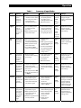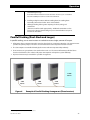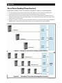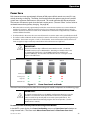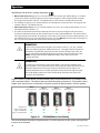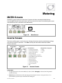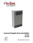
1
Radian Series Inverter/Charger GS7048E GS3548E Operator’s Manual About OutBack Power Technologies OutBack Power Technologies is a leader in advanced energy conversion technology. OutBack products include true sine wave inverter/chargers, maximum power point tracking charge controllers, and system communication components, as well as circuit breakers, batteries, accessories, and assembled systems. Grid/Hybrid™ As a leader in off-grid energy systems designed around energy storage, OutBack Power is an innovator in Grid/Hybrid system technology, providing the best of both worlds: grid-tied system savings during normal or daylight operation, and off-grid independence during peak energy times or in the event of a power outage or an emergency. Grid/Hybrid systems have the intelligence, agility and interoperability to operate in multiple energy modes quickly, efficiently, and seamlessly, in order to deliver clean, continuous and reliable power to residential and commercial users while maintaining grid stability. Contact Information Address: Corporate Headquarters 17825 – 59th Avenue N.E. Suite B Arlington, WA 98223 USA European Office Hansastrasse 8 D-91126 Schwabach, Germany Telephone: +1.360.435.6030 +1.360.618.4363 (Technical Support) +1.360.435.6019 (Fax) +49.9122.79889.0 +49.9122.79889.21 (Fax) Email: [email protected] Website: http://www.outbackpower.com Disclaimer UNLESS SPECIFICALLY AGREED TO IN WRITING, OUTBACK POWER TECHNOLOGIES: (a) MAKES NO WARRANTY AS TO THE ACCURACY, SUFFICIENCY OR SUITABILITY OF ANY TECHNICAL OR OTHER INFORMATION PROVIDED IN ITS MANUALS OR OTHER DOCUMENTATION. (b) ASSUMES NO RESPONSIBILITY OR LIABILITY FOR LOSS OR DAMAGE, WHETHER DIRECT, INDIRECT, CONSEQUENTIAL OR INCIDENTAL, WHICH MIGHT ARISE OUT OF THE USE OF SUCH INFORMATION. THE USE OF ANY SUCH INFORMATION WILL BE ENTIRELY AT THE USER’S RISK. OutBack Power Technologies cannot be responsible for system failure, damages, or injury resulting from improper installation of their products. Information included in this manual is subject to change without notice. Notice of Copyright Radian Series Inverter/Charger Operator’s Manual © 2014 by OutBack Power Technologies. All Rights Reserved. Trademarks OutBack Power, the OutBack Power logo, FLEXpower ONE, and Grid/Hybrid are trademarks owned and used by OutBack Power Technologies, Inc. The ALPHA logo and the phrase “member of the Alpha Group” are trademarks owned and used by Alpha Technologies Inc. These trademarks may be registered in the United States and other countries. Date and Revision September 2015, Revision B (firmware revision 001.005.xxx) Part Number 900-0145-01-01 Rev B Table of Contents Introduction ................................................................................................. 5 Audience ................................................................................................................................................................................. 5 Symbols Used ........................................................................................................................................................................ 5 General Safety ....................................................................................................................................................................... 5 Welcome to OutBack Power Technologies ................................................................................................................. 6 Inverter Functions ................................................................................................................................................................ 6 GS7048E .............................................................................................................................................................................................. 7 GS3548E .............................................................................................................................................................................................. 7 Inverter Controls ................................................................................................................................................................... 8 On/Off Switch .................................................................................................................................................................................... 8 MATE3 System Display and Controller ..................................................................................................................................... 8 Commissioning ............................................................................................ 9 Functional Test ...................................................................................................................................................................... 9 Pre-startup Procedures .................................................................................................................................................................. 9 Startup ................................................................................................................................................................................................. 9 Powering Down ..............................................................................................................................................................................11 Adding New Devices.....................................................................................................................................................................11 Firmware Updates .........................................................................................................................................................................12 Operation .................................................................................................. 13 Inverter Functionality ...................................................................................................................................................... 13 Description of AC Input Modes .................................................................................................................................... 13 Generator ..........................................................................................................................................................................................14 Support..............................................................................................................................................................................................14 Grid Tied ............................................................................................................................................................................................15 UPS ......................................................................................................................................................................................................17 Backup ...............................................................................................................................................................................................18 Mini Grid............................................................................................................................................................................................18 GridZero ............................................................................................................................................................................................19 Description of Inverter Operations ............................................................................................................................. 22 Inverting ............................................................................................................................................................................................22 DC and AC Voltages ..........................................................................................................................................................................................22 AC Frequency ......................................................................................................................................................................................................23 Search .....................................................................................................................................................................................................................23 Input ...................................................................................................................................................................................................24 AC Current Settings ...........................................................................................................................................................................................24 AC Source Acceptance .....................................................................................................................................................................................25 Generator Input ..................................................................................................................................................................................................26 Transfer ..................................................................................................................................................................................................................26 Battery Charging ............................................................................................................................................................................27 Charge Current....................................................................................................................................................................................................27 Charge Cycle ........................................................................................................................................................................................................27 Charging Graphs ................................................................................................................................................................................................28 Charging Steps ....................................................................................................................................................................................................29 New Charging Cycle ..........................................................................................................................................................................................31 Equalization..........................................................................................................................................................................................................33 Battery Temperature Compensation ..........................................................................................................................................................33 Offset ..................................................................................................................................................................................................35 900-0145-01-01 Rev B 1 Table of Contents Multiple-Inverter Installations (Stacking) ...............................................................................................................................36 Parallel Stacking (Dual-Stack and Larger) .................................................................................................................................................37 Three-Phase Stacking (Three Inverters) .....................................................................................................................................................38 Power Save ...........................................................................................................................................................................................................39 Auxiliary Terminals ........................................................................................................................................................................43 System Display-Based Functions ................................................................................................................................. 47 Advanced Generator Start (AGS) ..............................................................................................................................................47 Grid Functions .................................................................................................................................................................................47 High Battery Transfer (HBX)............................................................................................................................................................................47 Grid Use Time ......................................................................................................................................................................................................48 Load Grid Transfer .............................................................................................................................................................................................48 Metering .................................................................................................... 49 MATE3 Screens ................................................................................................................................................................... 49 Inverter Screens ..............................................................................................................................................................................49 Battery Screen .................................................................................................................................................................................50 Troubleshooting ......................................................................................... 51 Basic Troubleshooting ..................................................................................................................................................... 51 Module Select..................................................................................................................................................................................56 Error Messages ................................................................................................................................................................... 57 Warning Messages ............................................................................................................................................................ 58 Temperature Events ......................................................................................................................................................................59 GT Warnings.....................................................................................................................................................................................59 Disconnect Messages ...................................................................................................................................................... 60 Sell Status ............................................................................................................................................................................. 61 Specifications ............................................................................................. 63 Electrical Specifications ................................................................................................................................................... 63 Mechanical Specifications .............................................................................................................................................. 64 Environmental Specifications ....................................................................................................................................... 64 Temperature Derating..................................................................................................................................................................65 Certifications ....................................................................................................................................................................... 65 Compliance.......................................................................................................................................................................... 65 Firmware Revision ............................................................................................................................................................. 67 Default Settings and Ranges ......................................................................................................................................... 67 Definitions............................................................................................................................................................................ 70 Index ......................................................................................................... 71 2 900-0145-01-01 Rev B Table of Contents List of Tables Table 1 Table 2 Table 3 Table 4 Table 5 Table 6 Table 7 Table 8 Table 9 Table 10 Table 11 Table 12 Table 13 Table 14 Table 15 Table 16 Table 17 Table 18 Summary of Input Modes ............................................................................................................. 21 Charge Currents for Radian Models .......................................................................................... 27 Offset Interaction with AC Source ............................................................................................. 35 Changing Master Power Save Levels (GS7048E) .................................................................. 42 Aux Mode Functions....................................................................................................................... 46 Troubleshooting............................................................................................................................... 51 Error Troubleshooting.................................................................................................................... 57 Warning Troubleshooting ............................................................................................................ 58 Temperature Events........................................................................................................................ 59 GT Warnings ...................................................................................................................................... 59 Disconnect Troubleshooting ...................................................................................................... 60 Sell Status Messages ...................................................................................................................... 61 Electrical Specifications for Radian Models ........................................................................... 63 Mechanical Specifications for Radian Models ...................................................................... 64 Environmental Specifications for Radian Models ............................................................... 64 AS4777.3 Acceptance Settings .................................................................................................. 66 Radian Inverter Settings ............................................................................................................... 67 Terms and Definitions ................................................................................................................... 70 List of Figures Figure 1 Figure 2 Figure 3 Figure 4 Figure 5 Figure 6 Figure 7 Figure 8 Figure 9 Figure 10 Figure 11 Figure 12 Figure 13 Figure 14 Figure 15 Figure 16 Figure 17 Figure 18 Radian Series Inverter/Charger .................................................................................................... 7 MATE3 System Display and Controller...................................................................................... 8 AC Test Points ................................................................................................................................... 10 Charging Stages Over Time ......................................................................................................... 28 Charging Stages Over Time (24/7) ............................................................................................ 28 Repeated Charging Cycles ........................................................................................................... 32 OutBack HUB4 and MATE3 .......................................................................................................... 36 Example of Parallel Stacking Arrangement (Three Inverters) ........................................ 37 Example of Three-Phase Stacking (Three Inverters) .......................................................... 38 Example of Three-Phase Stacking (Nine Inverters) ............................................................ 38 Power Save Levels and Loads ..................................................................................................... 39 GS3548E Power Save Priority ...................................................................................................... 40 GS7048E Power Save Priority ...................................................................................................... 41 Home Screen..................................................................................................................................... 49 Inverter Screens ............................................................................................................................... 49 Battery Screen .................................................................................................................................. 50 AC Test Points ................................................................................................................................... 51 Temperature Derating................................................................................................................... 65 900-0145-01-01 Rev B 3 Table of Contents This page intentionally left blank. 4 900-0145-01-01 Rev B Introduction Audience This manual provides instructions for setup and operation of the product. It does not cover installation. The manual is intended to be used by anyone required to operate the Radian Series Inverter/Charger. Operators must be familiar with all the safety regulations pertaining to operating power equipment of this type as required by local code. Operators are advised to have basic electrical knowledge and a complete understanding of this equipment’s features and functions. Do not use this product unless it has been installed by a qualified installer in accordance with the Radian Series Inverter/Charger Installation Manual. Symbols Used WARNING: Hazard to Human Life This type of notation indicates that the hazard could be harmful to human life. CAUTION: Hazard to Equipment This type of notation indicates that the hazard may cause damage to the equipment. IMPORTANT: This type of notation indicates that the information provided is important to the installation, operation and/or maintenance of the equipment. Failure to follow the recommendations in such a notation could result in voiding the equipment warranty. MORE INFORMATION When this symbol appears next to text, it means that more information is available in other manuals relating to the subject. The most common reference is to the Radian Series Inverter/Charger Installation Manual. Another common reference is the system display manual. General Safety WARNING: Limitations on Use This equipment is NOT intended for use with life support equipment or other medical equipment or devices. WARNING: Reduced Protection If this product is used in a manner not specified by GS product literature, the product’s internal safety protection may be impaired. CAUTION: Equipment Damage Only use components or accessories recommended or sold by OutBack Power Technologies or its authorized agents. 900-0145-01-01 Rev B 5 Introduction Welcome to OutBack Power Technologies Thank you for purchasing the OutBack Radian Series Inverter/Charger. It is designed to offer a complete power conversion system between batteries and AC power. As part of an OutBack Grid/Hybrid™ system, it can provide off-grid power, grid backup power, or grid-interactive service which sells excess renewable energy back to the utility. Inverter Functions Battery-to-AC inverting which delivers power to run backup loads and other functions Provides single-phase output Adjustable range of output voltage Settable nominal output frequency AC-to-battery charging (OutBack systems are battery-based) Accepts a wide variety of AC sources Requires single-phase input Uses battery energy stored from renewable resources Can utilize stored energy from many sources (PV arrays, wind turbines, etc.) OutBack FLEXmax charge controllers will optimize PV power production as part of a Grid/Hybrid system Dual AC inputs allow direct connection to utility grid and AC generator Rapid transfer between AC source and inverter output with minimal delay time Uses MATE3 System Display and Controller (sold separately) for user settings as part of a Grid/Hybrid system Stackable in parallel configuration up to ten inverters Stackable in three-phase configuration with up to nine inverters (using HUB10.3 Communications Manager) Field-upgradeable firmware Seven selectable input modes for different applications Generator Support Grid Tied UPS Backup Mini Grid GridZero Certified to IEC 62109-1 IMPORTANT: The Radian Series Inverter/Charger is not intended for use with the OutBack MATE or MATE2 System Display and Controller. It is only compatible with the MATE3 System Display and Controller. 6 900-0145-01-01 Rev B Introduction Figure 1 Radian Series Inverter/Charger GS7048E 7000 watts (7 kW) continuous power at 48 Vdc 16.3 kVA peak surge capacity Modular internal design allows low idle consumption and high efficiency at high or low power operation GS3548E 3500 watts (3.5 kW) continuous power at 48 Vdc 8.2 kVA peak surge capacity NOTE: This product has a settable AC output range. In this book, many references to the output refer to the entire range. However, some references are made to 230 Vac or 50 Hz output. These are intended as examples only. 900-0145-01-01 Rev B 7 Introduction Inverter Controls The Radian inverter has no external controls. It can operate normally without an external control or interface. Basic modes and settings are pre-programmed at the factory. (See page 67 for default settings.) However, certain external devices can be used to operate or program the Radian. On/Off Switch The inverter can be equipped with a switch to turn it on and off. This switch is not sold as an inverter accessory; a common toggle switch can be used. It is wired to the Switch INV auxiliary terminals. (See the Radian Series Inverter/Charger Installation Manual for more information on wiring the switch.) This switch controls the inverting function only; it does not control the charger or any other function. MATE3 System Display and Controller The Radian inverter has no display or LED indicators. It is not possible to monitor its status or operating mode without a metering device. The MATE3 System Display and Controller (sold separately) is designed to accommodate programming and monitoring of a Grid/Hybrid power system. The MATE3 provides the means to adjust the factory default settings to correctly match the installation where needed. It provides the means to monitor system performance and troubleshoot fault or shutdown conditions. It also has data logging and interface functions using the Internet. Once settings are modified using a MATE3, the MATE3 can be removed from the installation. The settings are stored in the nonvolatile memory of the Radian inverter. However, it is highly recommended to include a MATE3 as part of the system. This provides the means to monitor system performance and respond quickly should it be necessary to correct a fault or shutdown condition. The MATE3’s Configuration Wizard is capable of automatically configuring inverters to a series of preset values. This is often more efficient than attempting to manually program each setting in each inverter. Affected fields include system type, battery charging, and AC source configuration. NOTE: The Radian inverter can only be used with MATE3 firmware revision 002.017.xxx or higher. IMPORTANT: Some functions are not based in the inverter, but are part of the MATE3 system display’s firmware. They will not function if the system display is removed. These functions are listed beginning on page 46. Figure 2 8 MATE3 System Display and Controller 900-0145-01-01 Rev B Commissioning Functional Test WARNING: Shock Hazard and Equipment Damage It is necessary to remove the inverter cover to perform these tests. The components are close together and carry hazardous voltages. Use appropriate care to avoid the risk of electric shock or equipment damage. Pre-startup Procedures 1. 2. 3. 4. 5. Ensure all DC and AC overcurrent devices are opened, disconnected, or turned off. Double-check all wiring connections. Confirm that the total load does not exceed the inverter’s wattage. (See page 22.) Inspect the work area to ensure tools or debris have not been left inside. Using a digital voltmeter (DVM) or standard voltmeter, verify battery voltage. Confirm the voltage is correct for the inverter model. Confirm the polarity. 6. Connect the MATE3 system display, if present. CAUTION: Equipment Damage Incorrect battery polarity will damage the inverter. Excessive battery voltage also may damage the inverter. This damage is not covered by the warranty. IMPORTANT: Prior to programming (see Startup), verify the operating frequency of the AC source. This is necessary for correct AC operation. The default setting is 50 Hz, but this can be changed to 60 Hz. Startup It is highly recommended that all applicable steps be performed in the following order. However, if steps are inapplicable, they can be omitted. If the results of any step do not match the description, see the Troubleshooting section on page 50. To start a single-inverter system: 1. Close the main DC circuit breakers (or connect the fuses) from the battery bank to the inverter. Confirm that the system display is operational, if present. 2. If a system display is present, perform all programming for all functions. These functions may include AC input modes, AC output voltage, input current limits, battery charging, generator starting, and others. AC input modes are described beginning on page 13 and are summarized on page 21. The inverter’s individual operations are described beginning on page 22. 3. Turn on the inverter using the MATE3 or external switch. The Radian’s default condition is Off. Do not turn on any AC circuit breakers at this time. 900-0145-01-01 Rev B 9 Commissioning Metal pads are located at these locations. In commissioning, AC voltages can be measured at this series of test points. Figure 3 AC Test Points 4. Using a DVM or voltmeter, verify 230 Vac (or appropriate voltage) between the “L” and “N” OUT terminals. (See Figure 3 for AC test points.) The inverter is working correctly if the AC output reads within 10% of 230 Vac or the programmed output voltage. 5. Proceed past the items below to Step 6 on the next page. To start a multiple-inverter (stacked) system: 1. Close the main DC circuit breakers (or connect the fuses) from the battery bank to the inverter. Repeat for every inverter present. 2. With the system display, perform any programming for stacking and all other functions. These functions may also include AC input modes, AC output voltage, input current limits, battery charging, generator starting, and others. When stacking in parallel, all slave inverters will observe the programming settings for the master. They do not need to be programmed individually. When stacking in three-phase configuration, all subphase masters will observe the AC input mode and many of the settings used by the master inverter. However, they need to be individually programmed as appropriate for AC output voltage and frequency. They also need to be programmed for AC input voltage and frequency (for both AC inputs). All slaves will observe the programming settings for the master or for their individual subphase master. They do not need to be programmed individually. AC input modes are described beginning on page 13 and are summarized on page 21. The inverter’s individual operations are described beginning on page 22. Stacking is described beginning on page 36. The MATE3 Configuration Wizard may be used to assist programming. 3. Turn on the master inverter using the system display (or external switch, if one has been installed). The Radian’s default condition is Off. Do not turn on any AC circuit breakers at this time. 4. Using a DVM or voltmeter, verify 230 Vac (or appropriate voltage) between the master “L” and “N” OUT terminals. (See Figure 3 for AC test points.) 10 The inverter is working correctly if the AC output reads within 10% of 230 Vac or the programmed output voltage. If subphase masters are used in three-phase configuration, perform this test on each subphase master. If necessary, confirm appropriate voltages from one inverter to the next. 900-0145-01-01 Rev B Commissioning 5. Using the system display, temporarily bring each slave out of Silent mode by raising the Power Save Level of the master. (See page 39.) As each slave is activated, it will click and create an audible hum. Confirm that the system display shows no fault messages. Confirm that the output voltages are still correct. Individual slave voltage readings are not necessary since all slave inverters are in parallel. When this test is finished, return the master to its previous settings. After output testing is completed, perform the following steps: 6. Close the AC output circuit breakers. If AC bypass switches are present, place them in the normal (non-bypass) position. Do not connect an AC input source or close any AC input circuits. 7. Use a DVM to verify correct voltage at the AC load panel. 8. Connect a small AC load and test for proper functionality. 9. Close the AC input circuit breakers and connect an AC source. Using a DVM on the correct input, check the “L” and “N” input terminals for 230 Vac (or appropriate voltage from the AC source.) If a system display is present, confirm that the inverter accepts the AC source as appropriate for its programming. (Some modes or functions may restrict connection with the source. If one of these modes has been selected for the system, it may not connect.) Check the system display indicators for correct performance. NOTE: If any Phase B or Phase C inverters are wired to the wrong AC source phases, the inverters will not connect to the AC source and will display a Phase Loss warning. See page 58. 10. If the charger is activated, the inverter will perform a battery charging cycle after powering up. This can take several hours. If restarted after a temporary shutdown, the inverter may skip most or all of the charging cycle. Confirm that it is charging as appropriate by using the system display. 11. Test other functions which have been enabled, such as generator start, selling, or search mode. 12. Compare the DVM’s readings with the system display meter readings. If necessary, the system display’s readings can be calibrated to match the DVM more accurately. Calibrated settings include AC input voltage for the Grid and Gen inputs, AC output voltage, and battery voltage. Powering Down If steps are inapplicable, they can be omitted. However, it is highly recommended that all applicable steps be performed in the following order. These steps will completely isolate the inverter. To remove power from the system: 1. Turn off all load circuits and AC input sources. 2. Turn off all renewable energy circuits. 3. Turn each inverter OFF using the MATE3 system display or external switch. 4. Turn off the main DC overcurrent devices for each inverter. Adding New Devices When adding new devices to the system, first turn off the system according to the preceding instructions. After adding new devices, perform another functional test, including programming. 900-0145-01-01 Rev B 11 Commissioning Firmware Updates IMPORTANT: All inverters will shut down during firmware updates. If loads need to be run while updating the firmware, bypass the inverter with a maintenance bypass switch. Communication cables must remain connected and DC power must remain on. Interrupted communication will cause the update to fail and the inverter(s) may not work afterward. Inverters automatically update one at a time beginning with Port 1. Each requires about 5 minutes. Updates to the Radian’s internal programming are periodically available at the OutBack website www.outbackpower.com. If multiple inverters are used in a system, all units must be upgraded at the same time. All units must be upgraded to the same firmware revision. If multiple stacked Radian inverters are used with different firmware revisions, any inverter with a revision different from the master will not function. (See the stacking section on page 36.) The MATE3 will display the following message: An inverter firmware mismatch has been detected. Inverters X, Y, Z 1 are disabled. Visit www.outbackpower.com for current inverter firmware. NOTES: 1 The port designations for the mismatched inverters are listed here. 12 900-0145-01-01 Rev B Operation Inverter Functionality The inverter is capable of being used for many applications. Some of the inverter’s operations occur automatically. Others are conditional or must be enabled manually before they will operate. Most of the inverter’s individual operations and functions can be programmed using the system display. This allows customization or fine tuning of the inverter’s performance. The Radian inverter has two sets of input connections, which are labeled Grid and Gen. Two different AC sources can be connected during inverter installation. Before operating the inverter: The operator needs to define the application and decide which functions will be needed. The Radian inverter is programmed with seven AC input modes. Each mode has certain advantages which make it ideal for a particular application. Some modes contain functions unique to that mode. The modes are described in detail following this section. To help decide which mode will be used, the basic points of each mode are compared in Table 1 on page 21. Apart from the input modes, Radian inverters possess a set of common functions or operations. These operations are described in detail beginning on page 22. Most of these items operate the same regardless of which input mode is selected; however, this is not always true. The exceptions are noted where appropriate. NOTE: The Radian’s battery charger uses the same programming and settable limits regardless of which input is used. It does not have independent charger settings on each input. Each distinct mode, function, or operation is accompanied by a symbol representing the inverter and that operation: These items represent the input from the AC DC source, the output to the AC loads, DC functions TRANSFER (inverting, charging, etc), and the transfer relay. AC IN AC OUT Arrows on each symbol represent power flow. The symbols may have other features depending on the operation. Description of AC Input Modes These modes control aspects of how the inverter interacts with AC input sources. Each mode is intended to optimize the inverter for a particular application. The names of the modes are Generator, Support, Grid Tied, UPS, Backup, Mini Grid, and GridZero. The modes are summarized and compared in Table 1. Both of the Radian’s inputs, Grid and Gen, can be programmed for separate modes. The Grid input can be set in the Grid AC Input Mode and Limits menu. The Gen input can be set in the Gen AC Input Mode and Limits menu. NOTE: The input terminals are labeled for grid and generator due to common conventions, not because of inverter requirements. Each input can accept any AC source as long as it meets the requirements of the Radian inverter and the selected input mode. If necessary, the Gen terminals can 900-0145-01-01 Rev B 13 Operation accept grid power. The opposite is also true. However, if using the Gen Alert or AGS functions, the generator must use the Gen terminals. See page 43 (Gen Alert) and page 47 (AGS).) When multiple inverters are stacked together in parallel, the master inverter’s input mode is imposed on all slaves. The slave settings are not changed; they retain any mode that was previously programmed. However, the slave will ignore its own input mode and use that of the master. This also applies to any parameters in the mode menu (Voltage Limit, Connect Delay, and so on). If inverters are stacked using subphase masters, the subphase masters will observe the AC input mode and many of the settings used by the master inverter. However, they need to be individually programmed as appropriate for AC output voltage and frequency. They also need to be programmed for AC input voltage and frequency (for both AC inputs). See the stacking section on page 36 for explanation of both parallel and subphase master (three-phase) stacking. The following pages compare the various aspects of each input mode. Generator The Generator mode allows the use of a wide range of AC sources, including generators with a rough or imperfect AC waveform. In other modes, a “noisy” or irregular waveform may not be accepted by the inverter. (Self-excited induction generators may require this mode when used with the Radian.) Generator allows these waveforms to be accepted. The charging algorithm of this mode is designed to work well with AC generators regardless of power quality or regulation mechanism. The generator must still comply with the inverter’s nominal input specifications. (See page 24.) BENEFITS: The Radian inverter will charge the batteries from the generator even when the generator is undersized, of low quality, or has other problems. See page 26 for recommended parameters for sizing a generator. In cases where utility grid power is unstable or unreliable, Generator mode may allow the Radian inverter to accept the power. A programmable delay time is available which will allow a generator to stabilize before connection. In the MATE3, this menu item is Connect Delay. It is available in both the Grid AC Input Mode and Limits and the Gen AC Input Mode and Limits menus, depending on which input is being programmed. NOTES: Any AC fluctuations that are accepted by the inverter will be transferred to the output. The loads will be exposed to these fluctuations. It may not be advisable to install sensitive loads under these conditions. The name of Generator mode does not mean that the Radian requires a generator input when using this mode. The use of this mode does not require the use of the Gen input; either input can be used. Conversely, the Radian is not required to be placed in this mode just because a generator is installed. Support The Support mode is intended for systems that use the utility grid or a generator. In some cases the amount of current available from the source is limited due to size, wiring, or other reasons. If large loads need to be run, the Radian inverter augments (supports) the AC source. The inverter uses battery power and additional sources to ensure that the loads receive the power they demand. In the MATE3 system display, the Grid Input AC Limit dictates the maximum AC draw for the Grid 14 900-0145-01-01 Rev B Operation input. The Gen Input AC Limit sets the maximum draw for the Gen input. The Support function takes effect if the AC demand on either input exceeds the AC Limit setting. BENEFITS: Large inverter loads can be powered while staying connected to the AC input, even if the input is limited. The added battery power prevents overload of the input source, but the batteries are not in constant use. The Radian inverter will offset the loads with excess renewable energy if it is available from the batteries. See page 35 for more information. NOTES: IMPORTANT: The inverter will draw energy from the batteries when the loads exceed the appropriate AC Limit. With sustained loads and no other DC source, the batteries may discharge to the Low Battery Cut-Out point. The inverter will shut down with a Low Battery error. (See pages 22 and 57.) To prevent the loss of power, load use should be planned accordingly. IMPORTANT: A “noisy” or irregular AC source may prevent Support from working normally. The inverter will transfer the power, but will not support the source, charge the batteries, or interact with the current in any other way. This problem is more common with generators smaller than the wattage of the inverter. A programmable delay time is available which will allow an AC source to stabilize before connection. In the MATE3, this menu item is Connect Delay. It is available in both the Grid AC Input Mode and Limits and the Gen AC Input Mode and Limits menus, depending on which input is being programmed. Because the inverter limits the current draw from the AC source, it will reduce the charge rate as necessary to support the loads. If the loads equal the appropriate AC Limit setting, the charge rate will be zero. If the AC loads exceed the AC Limit setting, the Support function is activated by operating the charger in reverse. It will take power from the batteries and use it to support the incoming AC current. The Support function is not available in any other input mode. Grid Tied IMPORTANT: Selling power to the utility company requires the authorization of the local electric jurisdiction. How the utility company accommodates this will depend on their policies on the issue. Some may pay for power sold; others may issue credit. Some policies may prohibit the use of this mode altogether. Please check with the utility company and obtain their permission before using this mode. The Grid Tied mode allows the Radian inverter to become grid-interactive. This means that in addition to using power from the utility grid for charging and loads, the inverter can also convert excess battery power and sell it to the utility grid. Excess battery power usually comes from renewable energy sources, such as PV arrays, hydroelectric turbines, and wind turbines. 900-0145-01-01 Rev B 15 Operation The grid-interactive function is integrally tied with Offset operation and with the battery charger. See pages 35 and 27 for more information on these items. BENEFITS: Excess power is returned to the utility grid. The inverter will offset the loads with excess renewable energy if it is available from the batteries. If the excess energy is greater than the AC demand (the load size), the excess will be sold to the utility grid. Due to varying requirements in different locations around the world, the grid-interactive settings are adjustable. These adjustments are made in the Grid Interface Protection menu. This menu is only available to operators with installer-level access. There are firm rules concerning the acceptable voltage range, frequency range, clearance time during power loss, and reconnect delay when exporting power to the utility. Generally it is expected that the end user cannot alter the settings. The installer password must be changed from the default in order to get access to these settings. Once this password has been changed, the settings can only be accessed by using the installer password. See pages 67 and 69 for more information. The inverter’s operating frequency can be changed between 50 and 60 Hz using the Grid Interface Protection menu. This setting changes the inverter’s input acceptance parameters, as well as its output. See Table 17 beginning on page 67 for the locations of all menu items in the MATE3 menus. NOTES: The inverter has a delay before selling will begin. This delay has a default setting of one minute. During this time, the inverter will not connect to the utility grid. This setting is adjustable in the Grid Interface Protection menu. Upon initial connection to the utility grid, the inverter may be required to perform a battery charging cycle. This may delay the operation of the grid-interactive function. The grid-interactive function only operates when excess DC (renewable) power is available. The grid-interactive function is not available in any of the other input modes. When power is returned to the utility grid, it may be possible to reverse the utility meter. However, this depends on other loads in the system. Loads on the main panel (not on the inverter’s output) may consume power as fast as it is sold. The meter would not run backwards, even if the system display showed the inverter selling power. The result of selling would be to reduce AC power consumption, not reverse it. The amount of power an inverter can sell is not equal to its specified output wattage. The Maximum Sell Current can be decreased if it is necessary to limit the power sold. This item is available in the Grid Interface Protection menu. The amount of power that is sold is controlled by the utility grid voltage. The wattage sold is determined by this voltage multiplied by the current. For example, if the inverter sells 30 amps and the voltage is 231 Vac, the inverter will sell 6.93 kVA. If the voltage is 242 Vac, the inverter will sell 7.26 kVA. Additionally, output will vary with inverter temperature, battery type, and other conditions. This recommendation is specifically for the inverter’s grid-interactive function. In some cases, the source may be sized larger to account for environmental conditions or the presence of DC loads. This depends on individual site requirements. The grid-interactive function can only operate while the utility grid power is stable and within specific limits. In Grid Tied mode, the inverter will operate in accordance with the Grid Interface Protection settings. The default settings and ranges are listed in Table 17, which begins on page 67. If the AC voltage or frequency vary outside the Grid Interface Protection limits, the inverter will disconnect from the utility grid to prevent selling under unacceptable conditions. These limits override the AC source acceptance limits described on page 24, which are used in other input modes. 16 900-0145-01-01 Rev B Operation If the inverter stops selling or disconnects due to Grid Interface Protection, the MATE3 will show the reason. Sell Status messages are listed on page 61. Disconnect messages are listed on page 60. Often these messages will be the same. Due to varying requirements in different locations around the world, the grid-interactive settings are adjustable. However, this is only available to operators with installer-level access. There are firm rules concerning the acceptable voltage range, frequency range, clearance time during power loss, and reconnect delay when exporting power back to the utility. Generally it is expected that the settings cannot be altered by the end user. For this reason, it is necessary to change the installer password from the default in order to get access to these settings. Once this password has been changed, the settings can only be accessed by using the installer password. See pages 67 and 69 for more information. Before operating in Grid Tied mode, contact the utility company that provides power to the installation. They can provide information regarding the rules that must be followed in order to export power back to the utility. The items below are the selectable options for Grid Interface Protection. It may be necessary to provide these options to the utility company to make certain their standards are met. The utility may simply name a standard to be followed, as with AS 4777.3 for Australia. It may be necessary to look up the requirements for a local standard and program them accordingly. STAGE 1 Voltage (basic settings) Frequency Trip Over Voltage Clearance Time (seconds) Over Frequency Clearance Time (seconds) Over Voltage Trip (AC Voltage) Over Frequency Trip (Hertz) Under Voltage Clearance Time (seconds) Under Frequency Clearance Time (seconds) Under Voltage Trip (AC Voltage) Under Frequency Trip (Hertz) STAGE 2 Voltage (if required by utility) NOTE: The Frequency Trip settings are dependent on the inverter’s operating frequency, which must be set correctly. See pages 9 and 69. Over Voltage Clearance Time (seconds) Over Voltage Trip (AC Voltage) Under Voltage Clearance Time (seconds) Clearance Time (seconds) Under Voltage Trip (AC Voltage) Reconnect Delay (seconds) Mains Loss See Table 17 on page 67 for the default settings and ranges. UPS Failure In UPS mode, the Radian’s parameters have been optimized to reduce the response and transfer times. If the utility grid becomes unstable or is interrupted, the Radian can transfer to inverting in minimal time. This allows the system to support sensitive AC loads without interruption. BENEFITS: Constant power is provided to the loads with virtually no drop in voltage or current. NOTES: Due to the need for the Radian inverter to react quickly to AC source fluctuations, it must remain fully active at all times. The inverter requires a continuous consumption of 42 watts. For this reason, the Search function does not operate in this mode. (See page 23.) 900-0145-01-01 Rev B 17 Operation Backup Failure The Backup mode is intended for systems that have utility grid available as the primary AC source. This source will pass through the Radian inverter’s transfer circuit and will power the loads unless utility power is lost. If utility grid power is lost, then the Radian inverter will supply energy to the loads from the battery bank. When the utility power returns, it will be used to power the loads again. BENEFITS: This mode will continuously maintain the batteries in a fully-charged state, unlike the Support mode. It does not have the overhead consumption of the UPS mode. Mini Grid In Mini Grid mode, the Radian inverter automatically rejects an AC source and runs solely from battery (and renewable) energy. The inverter only connects to the AC source (usually the utility grid) when the batteries run too low. The Radian inverter runs on battery-supplied power for as long as the batteries can be sustained. It is expected that the batteries will also be charged from renewable sources such as PV. When the batteries become depleted, the system reconnects to the utility grid to operate the loads. The inverter will reconnect to the utility grid if the battery voltage decreases to the Connect to Grid set point and remains there for the Delay time period. These items are shown in Table 17 on page 67. While connected to the utility grid, the inverter’s charger can be set either on or off. If the charger is turned on, the inverter will proceed through a full charging cycle. Upon reaching float stage, the inverter will disconnect from the grid. If the inverter is connected to the utility grid and the charger is turned off, another DC source such as renewable energy should be present to charge the batteries. The inverter will observe the batteries as if it was performing the charge. When the batteries reach the required voltages and charging times to achieve float stage, the inverter will disconnect from the grid. This means that the regulator for the renewable source must be set to the same settings as the Radian (or higher). Check the settings of both devices as needed. See page 27 for more information on the battery charging cycle. BENEFITS: Mini Grid mode allows a system to minimize or eliminate dependence on the utility grid. This is only possible if certain conditions are met. See the Notes below. NOTES: The Radian inverter will offset the loads with excess renewable energy if it is available from the batteries. See page 35 for more information on Offset operation. However, the Offset function is inapplicable when the Radian disconnects from an AC source. The renewable energy supports the inverting function instead. This mode has similar priorities to the high-battery transfer (HBX) function used by the MATE3 system display. However, it is not compatible with HBX and cannot be used at the same time. When using Mini Grid mode, the system display should disable HBX to prevent conflicts. 18 900-0145-01-01 Rev B Operation Mini Grid mode is also incompatible with the Grid Use Time and Load Grid Transfer functions of the MATE3 system display. These functions do not have similar priorities to Mini Grid or HBX, but they do control the inverter’s connection and disconnection with the grid. Mini Grid should not be used with these functions. When deciding whether to use Mini Grid mode or HBX, the user should consider the aspects of each. Mini Grid logic is based in the Radian inverter and can function in the absence of the MATE3. HBX logic is based in the MATE3 and cannot function unless the MATE3 is installed and operating. Mini Grid can use utility grid power to fully recharge the batteries every time it reconnects to the grid. HBX can only do so under specific circumstances. HBX set points have a wide range of settings. Mini Grid uses settings intended to protect the batteries from excessive discharge; however, most of its settings are automatic and do not allow customization. HBX works more efficiently with a larger renewable source, but there is no specification for renewable size. Mini Grid cannot work properly unless the source is larger than the size of the loads. If this condition is not met, Mini Grid will not disconnect the inverter from the utility grid. HBX can be combined with the settings of any other input mode (Generator, UPS, etc.). The Mini Grid input mode is limited to its own settings and does not have access to certain functions of other modes. See page 47 for more information on HBX, Grid Use Time, and Load Grid Transfer. GridZero In GridZero mode, the Radian inverter remains grid-connected, but prioritizes the use of battery or renewable sources to run loads. It uses only renewable energy to recharge the batteries. The inverter tries to “zero” the use of the utility grid, drawing on AC power only when needed to supplement stored DC sources. Note that the inverter draws up to 1 Aac regardless of the DC sources. In the MATE3 system display, the selectable options are DoD Volts and DoD Amps. The inverter sends battery power to the loads when the batteries exceed the DoD Volts setting by 0.8 Vdc. As the battery voltage decreases to DoD Volts, the inverter reduces the current toward zero. It will maintain the batteries at this setting. The Radian inverter can manage large quantities of power. To prevent damage to the batteries from rapid discharge, the rate of discharge can be limited using the DoD Amps setting. This item should be set lower than the amperage provided by the renewable source. When DoD Volts is set low, this mode allows more renewable energy to be delivered from the batteries to the loads. However, it will also leave less of a battery reserve in the event of a grid failure. When DoD Volts is set high, the batteries will not be discharged as deeply and will retain more of a backup reserve. However, not as much renewable energy will be sent to the loads. The renewable energy source needs to exceed the size of all loads and possible losses. The renewable source must also charge the batteries. The inverter does not charge the batteries in GridZero mode. BENEFITS: This mode seamlessly blends the use of battery power and grid power. It puts renewable energy to the most effective use without selling power to the utility grid. GridZero mode minimizes dependence on the grid as long as certain conditions are met. The inverter remains connected to the utility grid in case the grid is needed. If large loads require the use of grid power, no transfer is necessary to support the loads. 900-0145-01-01 Rev B 19 Operation NOTES: IMPORTANT: Setting DoD Volts too low will severely discharge the batteries. The battery bank may not have sufficient reserve to provide backup in the event of a grid failure. To prevent the loss of power, load use and the DoD Volts setting should be planned accordingly. If the renewable energy source is not greater than the size of the inverter loads, this mode will not work well over time. The renewable source must be capable of charging the batteries as well as running the loads. This occurs when renewable energy production exceeds the DoD Amps setting. The inverter will offset the loads with excess renewable energy if it is available from the batteries. See page 35 for more information on Offset operation. However, the behavior of Offset in Grid Zero mode is different because it uses the DoD Volts exclusively. The inverter’s battery charger cannot be used in this mode. However, the menu settings and timer operations are not changed when this mode is selected. The battery should be discharged whenever possible in the attempt to “zero” the grid usage. If the DoD Amps setting is limited or loads are not present, the batteries will be unable to accept much renewable recharging the next time it is available. The renewable energy will be wasted, leaving the system dependent on the utility grid more than necessary. 20 900-0145-01-01 Rev B Operation Table 1 Mode Summary Benefits Cautions Intended Charger Can use AC that may be Will pass irregular or unusable in other modes Can charge even with a poor generator or low-quality AC source low-quality power to the output; could damage sensitive loads Offset unavailable Source: Generator Loads: Nonsensitive devices Performs three-stage charge and goes silent as specified by settings. Adds battery power to augment an AC source that has limited output Can use battery power Drains batteries during in conjunction with AC source Offset operation sends excess DC to loads support; intended for intermittent use only May not function with low-quality AC source Source: Grid or Generator Performs three-stage charge and goes silent as specified by user settings. Inverter sells excess power (renewable) to utility Bidirectional input Requires utility Can reduce utility bills approval Other approvals may be required depending on electrical codes Has exact requirements for accepting AC input Requires renewable energy source Generator Accepts power from an irregular or low-quality AC source Support GridTied Summary of Input Modes and still provide backup Offset operation sends excess DC to loads Any additional Offset excess is sold to the grid In grid failure, unit switches to batteries with fastest possible response time Quick backup for In grid failure, unit switches batteries to support loads; this is the default mode Simple use compared to Mini Grid Stays off grid most of the time; only uses grid when batteries low Can minimize/eliminate Will not work properly dependence on grid Offset operation sends excess DC to loads (but only when on grid) unless renewable source is above a certain size Conflicts with related modes in MATE3 Grid Zero On-grid but actual grid use is “zeroed out” with battery and renewable power; does not sell or charge Can minimize/eliminate Discharges batteries dependence on grid Offset operation sends excess DC to loads at adjustable rate Remains on-grid to avoid transfer problems while remaining on grid Will not work properly unless renewable source is above a certain size Battery charger inoperative UPS Backup 900-0145-01-01 Rev B sensitive devices during grid outage other modes; often used with generators for this reason Less idle power than UPS Does not drain battery as in Support Uses higher idle power than other modes Search function unavailable Offset unavailable Has none of the special functions described in other modes, including Offset Loads: Can be larger than AC source Source: Grid Loads: Any type Source: Grid Loads: PC, audio, video, etc. Source: Grid or Generator Loads: Any type Source: Grid Loads: Any type Source: Grid Loads: Any type Performs three-stage charge and goes silent as specified by user settings. Performs three-stage charge and goes silent as specified by user settings. Performs three-stage charge and goes silent as specified by user settings. Performs three-stage charge on reconnect; if charger is disabled, inverter emulates charge cycle from external source and reacts accordingly Charger inoperative; batteries must be charged using an external (renewable) energy source 21 Operation Description of Inverter Operations The items in this section are operations common to all Radian inverters. These are used in most or all of the input modes described in the preceding section. Some of the items in this section are functions which can be manually selected, enabled, or customized. Other items are general topics or applications for the inverter. These items may not have their own menus, but their activity can still be influenced or optimized by changing certain settings. Any of these items may need to be adjusted so that the inverter is best matched to a particular application. The operator should review these items to see which are applicable. All items described as settable or adjustable have set points which can be accessed using the system display. The default settings and ranges of adjustment are listed in Table 17 beginning on page 67 of this manual. Inverting This is the Radian inverter’s primary task. The inverter converts DC voltage from batteries into AC voltage that is usable by AC appliances. It will continue to do this as long as the batteries have sufficient energy. The batteries can be supplied or recharged from other sources, such as solar, wind, or hydroelectric power. The inverter’s design uses transformers and high-frequency H-Bridge FET modules to achieve the required high-wattage output. In the GS7048E, the dual design allows half the inverter to shut down for lower idle consumption when not in use. The Radian can deliver the rated wattage continuously at 25°C. The maximum output is derated at temperatures exceeding 25°C. See pages 63 and 65 for these wattages. Measure the total load wattage so that it does not exceed the Radian’s capacity. The Radian cannot maintain its AC voltage under an excessive load. It will shut down with a Low Output Voltage error. V DC and AC Voltages V The Radian inverter requires batteries to operate. Other sources may not maintain DC voltages that are consistent enough for the inverter to operate reliably. CAUTION: Equipment Damage Do not substitute other DC sources in place of the batteries. High or irregular voltages may damage the inverter. It is normal to use other DC sources with the batteries and the inverter, but not in place of the batteries. The following items will affect the inverter’s operation. These are only used when the inverter is generating AC power on its own. Low Battery Cut-Out: This function prevents the inverter from draining the batteries completely. When the DC voltage drops below a specified level for 5 minutes, the inverter will stop functioning. The MATE3 will give a Low Battery V error. This is one of the error messages described on page 57. It appears as an event on the MATE3 system display. This function is intended to protect both the batteries and the inverter’s output. (Continuing to invert on a low DC voltage may produce a distorted waveform.) This item is adjustable. 22 900-0145-01-01 Rev B Operation Low Battery Cut-In: The recovery point from Low Battery Cut-Out. When the DC voltage rises above this point for 10 minutes, the error will clear and the inverter will resume functioning. This item is adjustable. Connecting an AC source for the Radian to charge the batteries will also clear a low battery error. Output Voltage: The AC output voltage can be adjusted. Along with small changes, this allows the inverter to be used for different nominal (single-phase) voltages such as 220 Vac, 230 Vac, and 240 Vac. IMPORTANT: The output voltage can adjusted to a different nominal value for a particular region. Making this change will not affect the default input voltage range accepted by the inverter from an AC source. The input range must be adjusted manually. These changes should be made at the same time. (See AC Source Acceptance on page 24.) The inverter is also controlled by a high battery cut-out limit. If the DC voltage rises above this limit, the inverter will immediately stop functioning and give a High Battery V error. This is one of the error messages described on page 57. The shutdown occurs to protect the inverter from damage due excessive DC voltage. It appears as an event on the MATE3 system display. For the Radian inverter, the high battery cut-out voltage is 68 volts. It cannot be changed. If the voltage drops below this point, the inverter automatically recovers. AC Frequency Hz CAUTION: Equipment Damage Setting the inverter’s output frequency to deliver 50 Hz to 60-Hz loads, or setting it to deliver 60 Hz to 50-Hz loads, could damage sensitive devices. Make certain the inverter’s output frequency matches the installation. The inverter’s output can operate at a frequency of either 50 or 60 Hertz. This output frequency (and the AC acceptance frequency) can be changed with the Operating Frequency menu item. This requires high-level access. Due to the possibility of damage, access to this setting was restricted by placing it in the Grid Interface Protection menu. The installer password must be changed from the default in order to get access to this menu. Once this password has been changed, the Grid Interface Protection menu can only be accessed by using the installer password. This password can be changed in the system display. See page 17 for more information on the Grid Interface Protection menu. See Table 17, which begins on page 67, for the location of the Operating Frequency menu item. Search An automated search circuit is available to minimize the power draw when no loads are present. When enabled, the inverter does not always deliver full output. The output is reduced to brief pulses with a delay between them. These pulses are sent down the output lines to see if a resistance is present. Basically, the pulses “search” for a load. If a load is detected on the output, the inverter’s output increases to full voltage so that it can power the load. When the load is turned off, the inverter “goes to sleep” and begins searching again. The sensitivity of Search mode is in increments of approximately 0.1 Aac. The default is 6 increments, or about 0.6 Aac. A load which draws this amount or greater will “wake up” the inverter. 900-0145-01-01 Rev B 23 Operation NOTE: Due to load characteristics, these increments are only approximate and may not function exactly as listed. The pulse duration and the delay both have a time period that is measured in AC cycles. These two items and the load detection threshold are adjustable. Search mode may not be useful in larger systems with loads that require continuous power (e.g., clocks, answering machines, fax machines). Search mode may cause nuisance shutdowns, or it may sleep so rarely that there is no benefit. Some devices may not be easily detected by Search mode. Search is inoperative if the UPS input mode is in use. See page 17 for more information on this mode. Input When the Radian inverter input terminals are connected to a stable AC source, the inverter will synchronize itself with that source and use it as the primary source of AC power. Its transfer relay will engage, linking the AC source directly with the inverter’s output. It can also use the source to charge batteries. (See Battery Charging on page 27.) Two sets of AC input terminals are available. Both inputs are identical and can be used for any AC source. However, for easy reference, the first input has been labeled GRID (for the utility grid). The second input is labeled GEN (for a generator). These designations are also used in the menus of the MATE3 system display. Each input has a separate set of input criteria and input modes. The criteria, modes, and other programming for each input contain identical content. The independent inputs are intended to simplify the connection to multiple AC sources; however, the inverter can only use one input at a time. If both inputs are powered, the default setting is for the inverter to accept the GRID input. This can be changed. In the MATE3 system display, these priorities are selected using Input Priority in the AC Input and Current Limit menu. Seven input modes are available which affect the Radian inverter’s interactions with AC input sources. The Grid Tied mode allows the Radian to sell power using the input connection. The Support mode can use battery power to assist a smaller AC source. See page 21 for descriptions of these and other input modes. The loads powered by the inverter must not exceed the size of the inverter’s transfer relay. CAUTION: Equipment Damage Current draw in excess of the transfer relay rating can damage the transfer relay. This damage is not covered by warranty. Use protective devices of appropriate size. AC Current Settings A A A The AC current settings, Grid Input AC Limit and Gen Input AC Limit, control the amount of current that the inverter draws from the source(s). When using either of the Radian’s AC inputs, the appropriate setting limits the input. Adjust these settings to match the input circuit breakers. The adjustment is meant to protect a generator or source that cannot supply enough current for both charging and loads. If the combined charging and loads exceed the setting, the inverter will reduce its charge rate and give priority to the loads. If the loads exceed this number on their own, the charge rate will be reduced to zero. The Radian’s battery charger and grid-interactive function have individual settings. However, the AC Limit settings can also limit the charging or selling current. The Support input mode allows the Radian to support the AC source with battery power. See page 14. 24 900-0145-01-01 Rev B Operation The AC input current is used to power both loads and battery charging. The combined amount should not exceed the size of the AC overcurrent device or AC source. These devices should be sized appropriately during planning and installation of the inverter system. If multiple parallel inverters are installed with an AC source of limited amperage, the total combined amperage settings for all units must be less than the AC input circuit. The Configuration Wizard in the MATE3 can perform this calculation. However, the inverters do not perform this calculation. If the MATE3 or the Configuration Wizard are not used, divide the input size by the number of inverters and assign an equal part of the amperage to each port. AC Source Acceptance The input source must meet the following specifications to be accepted. This is true in all modes except Grid Tied (see NOTES on page 26): Voltage (both inputs): 208 to 252 Vac (default) Frequency (both inputs): If output frequency is set to 50 Hz (default), the input range of acceptance is 45 to 55 Hz. If the output frequency is set to 60 Hz, the input acceptance range is 55 to 65 Hz. See Table 17 on page 67 for the available selections for these items. When these conditions are met, the inverter will close its transfer relay and accept the input source. This occurs after a delay which is specified below. If the conditions are not met, the inverter will not accept the source. If it was previously accepted and then rejected, the inverter will open the relay and return to inverting power from the batteries. This occurs after a specified transfer delay, which is an adjustable menu item. IMPORTANT: The Radian’s output voltage can adjusted to a different nominal value for a particular region. (See page 23.) If this occurs, the source acceptance range should be adjusted to match this nominal value or the inverter may not accept the new source normally. The voltage limits can be adjusted to allow (or exclude) a source with weak or irregular voltages. These items are adjustable in the appropriate menu of the MATE3 (Grid AC Input Mode and Limits or Gen AC Input Mode and Limits). The settings are titled Voltage Limit Lower and Upper. There can be side effects to changing the range of allowed voltages. Each of the AC inputs has a settable Connect Delay. This is intended as a warmup period which allows an input source to stabilize before connection. The default setting for the Grid input is 0.2 minutes (12 seconds). The default setting for the Gen input is 0.5 minutes (30 seconds). These items are adjustable in the appropriate menu of the MATE3 (Grid AC Input Mode and Limits or Gen AC Input Mode and Limits). NOTES: The Grid Tied input mode does not use these acceptance limits and uses the Grid Interface Protection settings instead. (See page 17 for more information.) The inverter may not accept AC power if it meets the settings noted here but does not meet the Grid Interface Protection settings. AC Acceptance is controlled separately between the Radian inverter’s two inputs. An AC source that is unacceptable on one input may be acceptable on the other if the input mode or settings are different. Certain input modes such as Mini Grid may prevent the inverter from accepting AC power even if electrical conditions are met. (See page 18.) Several items external to the inverter may prevent the inverter from accepting AC power even if electrical conditions are met. Some examples are the High Battery Transfer, Grid Usage Time, or Load Grid Transfer 900-0145-01-01 Rev B 25 Operation functions, all of which are operated by the MATE3 system display. (See page 47.) Another example is the MATE3’s AC INPUT hot key menu, which can order all inverters to disconnect when set to Drop. Generator Input A generator should be sized to provide enough power for all inverters, both for loads and for battery charging. The generator’s voltage and frequency must match the inverter’s acceptance settings. It is usually recommended that the generator be sized at twice the wattage of the inverter system. Many generators may not be able to maintain AC voltage or frequency for long periods of time if they are loaded more than 80% of rated capacity. The generator is required to have a stable output before its power is accepted by the inverter. Some generators with less stable or uneven outputs may not be accepted. The use of the Generator input mode may assist with this problem. Transfer The inverter uses a transfer relay to alternate between the states of inverting and of accepting an AC source. Until the relay energizes, the output terminals are electrically isolated from the input that is in use. When it closes, the input and output terminals become electrically common. (The terminals for the unused input remain isolated during this time.) When the relay changes states, the physical transfer delay is approximately 25 milliseconds. The relay contacts are limited to 50 amps per phase or leg. The continuous loads on that output should never exceed this number. When connected to an AC source, the Radian inverter cannot limit the load current. An overload condition is possible. CAUTION: Equipment Damage Current draw in excess of the transfer relay rating can damage the transfer relay. This damage is not covered by warranty. Use protective devices of appropriate size. The inverter does not filter or clean up the power from the AC source. The voltage and power quality received by the output loads is the same as that of the source. If the voltage or quality do not meet the inverter’s input requirements, it will disconnect and return to the inverting mode. NOTES: To ensure a smoother transition, it may be advisable to raise the inverter’s lower acceptance limit. The default setting is 208 Vac. A higher setting will cause the inverter to transfer sooner in the event of a quality problem. If the AC source meets the inverter’s requirements but is irregular, any fluctuations will be transferred to the loads. If the loads are sensitive, it may be necessary to improve the quality of the AC source. The Generator input mode is intended to accept irregular or unfiltered AC sources and is more likely to do so than other modes. This should be considered before using this mode with sensitive loads. (See page 13.) If the charging function is turned off, the inverter will transfer power from the source but will not use it to charge. If the inverting function is turned off, the inverter will transfer (“pass through”) the source power when connected, but will not invert when the source is removed. In a stacked system, slaves are ordered to transfer at the same time as the master. If a slave does not sense an AC source at the same time as the master, it will continue inverting, and will experience a Phase Loss warning (see page 58). This appears as an Event on the MATE3 system display. 26 900-0145-01-01 Rev B Operation Battery Charging IMPORTANT: Battery charger settings need to be correct for a given battery type. Always follow battery manufacturer recommendations. Making incorrect settings, or leaving them at factory default settings, may cause the batteries to be undercharged or overcharged. Charge Current Batteries or battery banks usually have a recommended limit on the maximum current used for charging. Often this is calculated as a percentage or fraction of the battery capacity, represented by “C”. For example, C/5 would be a DC amperage figure that is 1/5 of the total amp-hours of the bank. Any chargers must be set so that the peak charge current does not exceed the recommended maximum. If multiple chargers are present (including other chargers besides the Radian), this calculation must accommodate the total combined current. The Radian’s charger may need to be set at less than maximum. The system display can be used to change charger settings. IMPORTANT: Although the recommended current is generally represented in DC amperes, the Charger AC Limit setting is measured in AC amperes, which are not measured on the same scale. To convert the recommended DC current into a usable AC figure, divide the DC figure by 4 and round up. The result can be used as a charger setting for the Radian inverter. Examples: 1) Battery bank consists of 8 x L16 FLA batteries in series. Recommended maximum charge current is 75 Adc. 75 ÷ 4 = 18.75 or 19 Aac. 2) Battery bank consists of 12 x OutBack EnergyCell 200RE VRLA batteries in series/parallel. Recommended maximum charge current is 90 Adc. 90 ÷ 4 = 22.5 or 23 Aac. The maximum DC charge rate for Radian models is specified in Table 13 on page 63. The actual Charger AC Limit setting is available in the AC Input and Current Limit menu of the MATE3 system display. See Table 17 on page 67. These numbers are also summarized in Table 2 below. If multiple Radian inverters are installed, divide the total current by the number of inverters and program each with the resulting number. Table 2 Charge Currents for Radian Models Model Maximum DC Output (sent to battery) Maximum AC Input (used from source) GS7048E 100 Adc 30 Aac GS3548E 50 Adc 15 Aac Charge Cycle The inverter uses a “three-stage” battery charging process which is designed around batteries using lead-acid chemistry. The three stages are Bulk, Absorption, and Float. These stages follow a series of steps, which are shown on graphs and described in text (see page 28). On the graphs, the transitions between steps are marked with vertical dotted lines. A circle indicates that the inverter has begun 900-0145-01-01 Rev B 27 Operation charging to a new voltage setting. A square indicates that the inverter has reached the setting (a horizontal dotted line). A triangle indicates that the inverter has stopped charging and is no longer using the previous set point. (The charging may have stopped for any of several reasons.) The battery voltage must drop to one of several low set points before the inverter resumes charging. Specialized Charging Lithium-ion, sodium-sulfur, and similar advanced battery technologies may require charger settings that are very different from the inverter’s defaults or the three-stage cycle in general. The Charging Steps section describes the individual selections and behavior. All charger settings are adjustable. The selection range for each step allows very different priorities from the defaults. For example, the Float voltage could be set higher than the Absorption voltage, or a step could be completely skipped.. Charging Graphs Figure 4 shows the progression of steps of the default three-stage charging cycle. Voltage Absorption Set Point Absorption (c.v.) Silent Bulk (c.c.) Float (c.c.) Float Set Point Float Timer (c.v.) Silent Float (c.c.) Float Timer Float Silent Float Timer (c.c.) (c.v.) Re-Float Set Point No Charging Time c.c. = Constant-Current Stage; charger can deliver up to inverter’s maximum (or maximum setting) c.v. = Constant-Voltage Stage; charger delivers the current needed to maintain voltage; usually tapers Figure 4 Charging Stages Over Time Figure 5 shows the charge cycle used by the inverter when the Float Time menu item is set to 24/7. This setting eliminates the Silent and Float Timer steps. The charger remains in Float continuously. The Float stage lasts until the AC source is removed. Voltage Absorption Set Point Absorption (c.v.) Bulk (c.c.) Float (c.v.) Float Set Point No Charge (Source removed) No Charge Time c.c. = Constant-Current Stage; can deliver up to the inverter’s limit c.v. = Constant-Voltage Stage; delivers only the current needed to maintain voltage; usually tapers Figure 5 28 Charging Stages Over Time (24/7) 900-0145-01-01 Rev B Operation Charging Steps The following items describe the operation and intended use for each individual charging step as shown in the graphs. Note that some charging cycles may not follow this exact sequence. These include cycles which were previously interrupted, and also customized charging. Each step describes how to defeat or customize the step if specialized charging is required. See page 31 for a description of multiple cycles when the charger is restarted after completion. This page also describes multiple cycles when the charger is restarted after being interrupted. For multiple inverters: The charging of parallel stacked inverters is synchronized by the master inverter. The charger settings of slave or subphase masters are ignored. Slaves or subphase masters use the master inverter settings. No Charging If the inverter is not charging, any of the following conditions may apply: The unit is not connected to a qualified AC source. If a generator is present, it may not be running. The unit is connected to an AC source but is in a mode or step (such as Silent) that does not use the charger. The unit is connected to an AC source but the charger has been turned off. Bulk Stage This is the first stage in the three-stage charge cycle. It is a constant-current stage which drives the battery voltage up. This stage typically leaves the batteries at 75% to 90% of their capacity, depending on the battery type, the exact charger setting, and other conditions. Voltage Used: Absorb Voltage setting. The default setting is 57.6 Vdc. The initial DC current may be as high as the charger’s maximum current, depending on conditions. It will begin at a high level, but will drop slightly as the voltage rises. This is not a decrease in charging; the charger delivers constant power in Bulk stage. It can be viewed as a wattage “tradeoff”; the increase in voltage results in a decrease in current for a constant wattage. To skip this step: Setting Absorb Voltage equal to Float Voltage will cause the charger to proceed through the normal three-stage cycle, but at a single voltage. Setting Absorb Time to zero will cause the charger to skip both the Bulk and Absorption stages and proceed directly to Float. This may not be desired if the intent is to include the Bulk stage but skip Absorption. Absorption Stage This is the second stage of charging. It is a constant-voltage stage. Current varies as needed to maintain the voltage, but will typically decrease to a very low number over time. This “tops off the tank”, leaving the batteries at essentially 100% of capacity. Voltage Used: Absorb Voltage setting. This setting is also used by Offset when in this stage. (See page 35.) For the three-stage cycle to proceed normally, this setting should be kept higher than the Float Voltage and Re-Bulk Voltage settings. Time limit: Absorb Time setting. This timer counts down from the inception of the Absorption stage until it reaches zero. The time remaining can be viewed in the system display. The Absorption timer does not reset to zero when AC power is disconnected or reconnected. It only resets to zero if it runs out, or if an external STOP BULK command is sent; otherwise it retains any remaining time. The Absorb Time setting is not a required minimum period for Absorption. It is only a maximum limit. The duration of Absorption is equal to the amount of time the Re-Bulk Voltage setting exceeds the battery voltage (up to the maximum Absorption limit). The counter adds more time to the Absorption 900-0145-01-01 Rev B 29 Operation period whenever the battery voltage decreases below this setting. (See page 31 for more information on how the timer works.) To skip this step: Setting Absorb Time to a very short duration will cause the charger to spend minimal time in Absorption once the Bulk stage is complete. Setting Absorb Time to zero will cause the charger to skip both the Bulk and Absorption stages and proceed directly to Float. This may not be desired if the intent is to skip Absorption but retain the Bulk stage. Silent This is not a charging stage, but a quiescent period between stages. The inverter remains on the AC source, but the charger is inactive. It enters this condition upon completing a timed stage such as Absorption, Float, or Equalize. In Silent, the batteries are not in significant use by the inverter, but they are also not being charged. The battery voltage will naturally decrease when not maintained by another means such as a renewable source. The term “Silent” is also used in an unrelated context regarding Power Save levels. See page 39. Voltage Used: Re-Float Voltage setting. When the battery voltage decreases to this point, the charger becomes active again. The default set point is 50.0 Vdc. To skip this step: Setting Float Time to 24/7 will cause the charger remain in Float continuously so that it does not proceed through the Silent, Bulk, Absorption, or Float timer steps. Float Stage This is the third stage of charging. It is sometimes known as maintenance charging. Float stage is initially a constant-current stage. The initial DC current may be as high as the charger’s maximum current, depending on conditions. This current is only sustained until the charger reaches the Float Voltage setting, after which the charger switches to constant-voltage operation. Float stage balances the batteries’ tendency to self-discharge (as well as balancing the draw of any other DC loads). It maintains the batteries at 100% of capacity. Voltage Used: Float Voltage setting. The default set point is 54.4 Vdc. This setting is also used by Offset when in this stage. (See page 35.) For the charger to work normally, this setting needs to be higher than the Re-Float Voltage setting. Time limit: This can vary. If the duration of the Float Time setting is less than the total time of the bulk and absorption stages, the charger will not enter Float and will go directly to Silent instead. See Float Timer. To skip this step: As noted, the charger will not enter Float if the Float Time setting is less than the total bulk and absorption times. Decreasing the Float Time setting to zero will cause the inverter to enter Silent as soon as the absorption stage is complete. The inverter will perform neither the constant-current nor the constant-voltage portions of Float. Setting Float Voltage equal to the Absorb Voltage level will cause the charger to proceed through the normal three-stage cycle, but at a single voltage. Float Timer This is not a separate stage of charging. In Figure 4 on page 28, it is marked as a separate step to note when the charger switches from constant-current to constant-voltage charging. When this occurs, the current varies as needed to maintain the Float Voltage, but typically drops to a low number. NOTE: The Float timer begins running any time the battery voltage exceeds the Float Voltage set point. This usually means that it begins running during the Bulk stage, once the battery voltage rises 30 900-0145-01-01 Rev B Operation above that level. Often the timer will expire before the bulk and absorption stages are complete. If this happens, the charger will not enter Float but will go directly to Silent. The charger only spends time in Float stage if the timer is still running. Time limit: Float Time setting. The charger will go Silent once the timer has expired (if another stage is not still in progress.) The Float timer is reset to its maximum amount whenever the batteries decrease to the Re-Float Voltage setting. To skip this step: Setting Float Time to 24/7 will cause the charger remain in Float continuously so that the Float timer no longer applies. (The charger also skips Bulk, Absorption, and Silent.) However, the charger can initiate a single three-stage charge if the criteria are met, after which it will return to continuous Float again. Silent Following the expiration of the Float timer, the unit enters (or re-enters) the Silent stage. The unit remains connected to the AC source, but the charger is inactive. The unit will continue cycling between Float and Silent for as long as the AC source is present. New Charging Cycle If the AC source is lost or disconnected, the unit will return to inverting mode if enabled. The battery voltage will begin to decrease due to loads or natural loss. When the AC source is restored, the inverter will return to the charging cycle. Re-Bulk If the battery voltage decreases due to discharge, the inverter will restart the cycle as soon as the AC source is available, beginning at Bulk stage. Voltage Used: Re-Bulk Voltage setting. The default set point is 49.6 Vdc. If the batteries do not decrease to the Re-Bulk point, the charger will not enter the Bulk stage and will return to its previous stage. Absorption Timer Time limit: Absorb Time setting. The charger will not necessarily run through its full duration, as this setting is not a required minimum period for Absorption. It is only a maximum limit. The duration of Absorption is equal to the amount of time the battery voltage was less than the Re-Bulk Voltage setting, up to the maximum limit. If the Absorption timer expired on the previous cycle, it is not reset afterward and retains a “remaining run time” of zero. Whenever the battery voltage decreases to Re-Bulk or lower, the Absorption timer will begin gaining time. For as long as the batteries remain below this voltage, the Absorption timer will gain an equal amount of time. This controls the duration of the Absorption stage. The intent was to avoid a “blind” cycle that operates regardless of conditions. The charger avoids maintaining the batteries at high voltages for excessive or unnecessary time. The Absorption timer continues this operation even if the charger is still on. For example, if the charger is in Float stage and there is a significant battery drain, the charger may not be able to maintain the batteries at the Float voltage. Once the batteries fall below the Re-Bulk point, the Absorption timer will begin accumulating time. (However, the accumulation will be minor, as this will also cause the charger to re-enter the Bulk stage.) The remaining charging steps will proceed as described on the previous pages. 900-0145-01-01 Rev B 31 Operation Cycle 1 Voltage AC Loss Absorption (c.v.) Absorption Set Point Float Set Point Cycle 4 Cycle 3 AC Loss AC Loss Absorption (c.v.) Float (c.c.) Float Timer (c.v.) Re-Float Set Point Re-Bulk Set Point Cycle 2 Silent Float (c.c.) Absorption (c.v.) Bulk (c.c.) Bulk (c.c.) Silent Float Timer (c.v.) Silent Silent Timer runs Timer accumulates Timer runs Timer runs Timer accumulates Time Figure 6 Repeated Charging Cycles Example of Multiple Cycles In Figure 6 (Cycle 1), the charger initially completes Absorption. When the Absorption timer expires, the charger goes Silent until battery voltage decreases to the Re-Float setting. The Float timer is reset to its maximum. The charger enters Float and proceeds until it is interrupted by a loss of AC power. Cycle 2 begins when the AC source is restored. During the AC loss, the battery voltage did not decrease to the Re-Float setting, so Float Time retains the remainder of the previous cycle. The charger returns to Float and completes the stage when its timer expires. It then goes Silent. During the Silent period, AC is lost again. The battery voltage decreases until it reaches the Re-Bulk set point. This causes the charger to prepare a new three-stage cycle from the beginning, but it cannot do so until the AC source is restored. In Cycle 1, Absorb Time had expired. It was not reset afterward and retained a “remaining run time” of zero. Whenever the battery voltage decreases to Re-Bulk or lower, the Absorption timer will begin accumulating run time. The first set of arrows below the graph show the length of time accumulated on the Absorption timer at the end of Cycle 2. Cycle 3 begins when the AC source is restored again. The charger begins a new cycle by entering Bulk stage. When it enters Absorption, the amount of time spent in this stage is equal to the amount of time accumulated at the end of Cycle 2. (The space between the first and second set of arrows is the same.) Absorption ends when the timer expires. This means that the length of Absorption may be shorter than the Absorb Time setting. During intermittent AC loss, the batteries may not be used enough to require a total recharge. In this example, the duration was also longer than the Float Time setting. Because the Float timer began running near the beginning of Cycle 3 (when the batteries exceeded the Float Voltage setting), the Float Time has also expired. The charger does not enter Float and goes Silent. During the Silent period, AC is lost again. The battery voltage decreases until it reaches the Re-Bulk set point, prompting a new charge cycle. The Absorption timer accumulates run time while the batteries are below this set point. The first set of barred arrows below the graph show the length of time accumulated on the Absorption timer. Note that the timer stops accumulating well before the beginning of Cycle 4 when the AC source is restored. The accumulation of the Absorption timer cannot exceed the Absorb Time setting. 32 When Cycle 4 begins, the charger proceeds through the Bulk stage and then the Absorption stage. (The space between the first and second set of barred arrows is the same.) The duration of Absorption is equal to Absorb Time, which is the maximum time allowed. At the end of Cycle 4, the Float Time has expired, so the charger goes Silent. 900-0145-01-01 Rev B Operation Equalization Equalization is a controlled overcharge that is part of regular battery maintenance. Equalization brings the batteries to a much higher voltage than usual and maintains this high voltage for a period of time. This has the result of removing inert compounds from the battery plates, and reducing stratification in the electrolyte. Equalization follows the same pattern as standard three-stage charging, as shown in the figures on page 28. However, instead of the Absorption voltage and time set points, it is controlled by the Equalize Voltage and Equalize Time settings in the MATE3. The Radian inverter can perform Offset when equalizing. (See page 35.) Equalize Voltage is also the reference voltage for Offset during equalization. This process must be started manually using the system display. The inverter cannot be programmed for automatic battery equalization. This is a safety measure. Equalization is normally performed only on flooded lead-acid batteries. The schedule for equalization varies with battery use and type, but it is usually performed every few months. If performed correctly, this process can extend battery life by a considerable amount. Equalization is not normally performed on nickel-technology batteries or any sort of sealed battery. CAUTION: Battery Damage Do not equalize OutBack EnergyCell batteries of any model. Do not equalize any sealed battery types (VRLA, AGM, Gel, or other) unless approved by the manufacturer. Some batteries may suffer severe damage from equalization. Contact the battery manufacturer for recommendations on equalization voltage, duration, schedule, and/or advisability. Always follow manufacturer recommendations for equalization. Battery Temperature Compensation Battery performance will change when the temperature varies above or below room temperature (77°F or 25°C). Temperature compensation is a process that adjusts battery charging to correct for these changes. When a battery is cooler than room temperature, its internal resistance goes up and the voltage changes more quickly. This makes it easier for the charger to reach its voltage set points. However, while accomplishing this process, it will not deliver all the current that the battery requires. As a result, the battery will tend to be undercharged. Conversely, when a battery is warmer than room temperature, its internal resistance goes down and the voltage changes more slowly. This makes it harder for the charger to reach its voltage set points. It will continue to deliver energy as time passes until the charging set points are reached. However, this tends to be far more than the battery requires, meaning it will tend to be overcharged. The Radian inverter, when equipped with the Remote Temperature Sensor (RTS) will compensate for changes in temperature. The RTS is attached to a single battery near the center of the bank, to achieve a representative temperature. The Radian inverter has a designated port for installing the RTS. 900-0145-01-01 Rev B 33 Operation If installed in a multiple-inverter system, only a single RTS is necessary. It must be plugged into the master inverter and will automatically control the charging of all slaves and all charge controllers. When charging, an inverter system with an RTS will increase or decrease the charge voltage by 5 mV per degree Celsius per battery cell. This setting affects the Absorption, Float, and Equalization set points. The Sell Voltage and Re-Float Voltage set points are not temperature compensated. The Equalization set points are not compensated in OutBack charge controllers. In a 48 Vdc system (24 cells, 2 volts each), this means 0.12 volts per degree Celsius above or below 25°C. Maximum compensation is ± 2.4 Vdc. EXAMPLES: A 48 Vdc system with batteries at 15°C will compensate its charging to 1.2 Vdc higher than the set points. A 48 Vdc system with batteries at 40°C will compensate its charging to 1.8 Vdc lower than the set points. Slope Some batteries require different amounts of compensation. The OutBack FLEXmax Extreme charge controller has an adjustable rate of compensation (“slope”) and is not limited to 5 mV. The FLEXmax Extreme can be networked with the Radian with the HUB Communications Manager. If this is done, the Radian can import the slope setting from the FLEXmax Extreme charge controller. NOTE: Temperature compensation only applies to the battery charging function. Other set points in the inverter, such as the AUX functions, are not compensated for temperature. 34 900-0145-01-01 Rev B Operation Offset This operation is designed to use excess battery energy to power the loads when an AC source is present. This allows the system to take advantage of renewable energy sources, in effect “offsetting” dependence on the AC source. A renewable energy source will raise the battery voltage as it charges the batteries. When the voltage exceeds a designated reference voltage, the Radian inverter begins drawing power from the batteries (discharging them) and using that power to offset usage of the AC source. The batteries are kept at equilibrium and are maintained at the reference voltage. The Radian inverter uses excess DC energy for offset under the following rules: If the load demand is higher than the exported power, the inverter’s use of the AC source is reduced. The exported amount of power has “offset” the same amount of demand on the AC source. (This is sometimes known as “selling to the loads”.) If the excess DC energy (and exported power) is equal or greater than the load demand, and the Radian is in the Grid Tied input mode, the inverter will sell the additional power to the utility grid. This is the key priority of the Grid Tied mode. The Radian inverter uses several set points as reference voltages for the Offset operation, particularly the battery charger settings. The charger settings Absorb Voltage, Float Voltage, and Equalize Voltage (as shown in the system display) are all used as reference voltages. Normally the charger regulates to these set points by adding power to the batteries. Offsetting does the opposite; it uses the same set points but regulates the voltage by removing power from the batteries. If none of the battery charger’s timers are active, the Offset voltage is Sell Voltage in the Grid-Tie Sell menu. This is true in any input mode where Offset is used, not just the Grid Tied input mode. The Grid Zero mode only uses a single reference voltage for Offset, the DoD Volts setting. NOTES: Offset operation is not available in the Generator, UPS, and Backup input modes. Offset operation is available in the Support, Grid Tied, and GridZero modes. Offset operation is available in the Mini Grid mode. However, it may not be used often since the Mini Grid priority is to avoid grid use. The Grid-Tie Enable menu item must be set to Y (yes) for Offset to work. This is true even if the inverter is not used in a grid-tied mode or application. Table 3 Mode Offset Interaction with AC Source Excess DC ≥ loads Excess DC < loads N/A; Offset operation does not function Generator Support Offsets load use, but also uses DC and batteries to support the AC source based on Support mode settings Grid Tied Sells excess to AC source (grid); remains connected N/A; Offset operation does not function UPS N/A; Offset operation does not function Backup Mini Grid Offsets load use with whatever power is available Offsets load use with whatever power is available; inapplicable if disconnected from utility grid Grid Zero 900-0145-01-01 Rev B Offsets load use, but only according to the DoD Volts setting 35 Operation Multiple-Inverter Installations (Stacking) Multiple inverters in a single system can support larger loads than a single inverter can handle. Installing inverters in this configuration is called “stacking”. Stacking inverters does not refer to physically placing one on top of another. It refers to how they are wired within the system and then programmed to coordinate activity. Stacking allows all units to work together as one system. The GS7048E and GS3548E models can stack up to ten units in parallel for increased capacity. For three-phase output, up to nine models can be stacked, three per phase. Stacking requires an OutBack HUB Communications Manager, as well as a MATE3 system display. There are usually other specialized stacking instructions during installation. A system of four or fewer units may use the HUB4. Systems of up to ten units require the HUB10 or HUB10.3. All interconnections between the products are made using CAT5 non-crossover cable. (See the Radian Series Inverter/Charger Installation Manual for more stacking instructions.) Each inverter needs to be assigned a status — “master” or “slave”. The master is the primary and most heavily used unit. Slave inverters provide assistance when the loads are more than the master can handle alone. In addition, in a three-phase system, “subphase masters” allow control of outputs that the master inverter cannot monitor. Programming involves using the MATE3 to assign a status and stacking value to the inverter on each port. See the MATE3 and HUB manuals for programming instructions. HUB4 Additional Ports Port 1 Figure 7 OutBack HUB4 and MATE3 MATE Port MATE3 IMPORTANT: 36 The Radian GS7048E can be stacked with the Radian GS3548E in either a parallel or a three-phase configuration. The master inverter must always be connected to port 1 on the HUB. Connecting it elsewhere, or connecting a slave to port 1, will result in backfeed or output voltage errors which will shut the system down immediately. All stacked Radian inverters must have the same firmware revision. If inverters are stacked with different firmware revisions, any unit with a revision different from the master will not function. The MATE3 will display 900-0145-01-01 Rev B Operation the following message: An inverter firmware mismatch has been detected. Inverters X, Y, Z 2 are disabled. Visit www.outbackpower.com for current inverter firmware. Installing multiple inverters without stacking them (or stacking them incorrectly) will result in similar errors and shutdown. Although stacking allows greater capacity, the loads, wiring, and overcurrent devices must still be sized appropriately. Additional terminations or bus bars may be required. Overloading may cause circuit breakers to open or inverters to shut down. Parallel Stacking (Dual-Stack and Larger) In parallel stacking, two or more inverters are stacked to create a single, common AC output. All inverters share a common input (AC source) and run loads on a common output bus. The master inverter provides the primary output. The slaves are connected to the same output and assist the master. The slave outputs are controlled directly by the master and cannot operate independently. Slave inverters can go into Power Save mode when not in use. The master will activate individual slaves based on load demand. This reduces idle power consumption and improves system efficiency. Up to ten inverters may be installed in a parallel arrangement. 21 kVA 230 Vac 7 kVA 230 Vac 7 kVA 230 Vac Figure 8 7 kVA 230 Vac Example of Parallel Stacking Arrangement (Three Inverters) 2 The port designations for the mismatched inverters are listed here. 900-0145-01-01 Rev B 37 Operation Three-Phase Stacking (Three Inverters) In three-phase stacking, inverters are stacked to create three AC outputs in a wye configuration. The three outputs operate independently of each other. Each can run in independent Search mode if desired, although this does not normally occur when three-phase loads are connected. Each output is 120° out of phase from the others. Any two outputs produce 400 Vac between them. (This voltage is nominal and may vary with output settings.) The outputs can be used to power three-phase loads when all inverters work together. Only three inverters, one per phase, may be installed in a three-phase arrangement when using the HUB4 or HUB10 products. Up to nine inverters, three per phase, may be stacked when using the HUB10.3. 7 kVA 230 Vac 7 kVA 230 Vac 7 kVA 230 Vac 7 kVA 230 Vac 21 kVA 230/400 Vac 7 kVA 230 Vac 7 kVA 230 Vac Figure 9 Example of Three-Phase Stacking (Three Inverters) 21 kVA 230 Vac 7 kVA 230 Vac (x3) 21 kVA 230 Vac 63 kVA 230/400 Vac 7 kVA 230 Vac (x3) 21 kVA 230 Vac 7 kVA 230 Vac (x3) Figure 10 38 Example of Three-Phase Stacking (Nine Inverters) 900-0145-01-01 Rev B Operation Power Save Each inverter consumes approximately 30 watts of idle power while it remains on, even if it is not actively inverting or charging. The Power Save function allows the option to put part of a parallel system into a quiescent state known as Silent mode. This mode minimizes the idle consumption. The inverters will come on again when the loads require power. (The term “Silent” is also used in an unrelated context during battery charging. See page 30.) When the load increases by approximately 2.5 kW, the master inverter activates one or more additional modules for assistance. When the load decreases to a lesser wattage (as detected by the master), the modules deactivate and return to Silent mode. Additional load increments of approximately 2.5 kW will activate additional modules. The first module in the master does not enter Silent mode. It remains active unless specifically turned off. The order in which additional modules activate (or return to Silent mode) is controlled by programming in the MATE3. The inverters are given a “rank”, or level number. Lower rank numbers activate when lesser loads are applied. Higher ranks only activate when the load increases to a high level. IMPORTANT: Power Save functionality is different between Radian models. The Radian GS3548E contains only one 4kW module. Activating one module is the same as activating the full inverter. The GS7048E contains two modules and operates differently. Do not confuse the behavior of each. See Figure 12 and Figure 13 for differences. Master Slave 1 Slave 2 Minimal load On Off Off Off Increasing load On On Off Off High load On On On Off Maximum load On On On On Figure 11 Slave 3 Power Save Levels and Loads The actual watt and ampere thresholds for activating each model are depicted on the following pages. IMPORTANT: It is highly recommended to use the MATE3 Configuration Wizard to set up this function. It is essential to set the slave Power Save Levels in sequential order. Failure to set them up correctly will cause erratic system performance. The Configuration Wizard automatically programs the correct priorities. (See the MATE3 owner’s manual.) To set these items manually without the Configuration Wizard: In the MATE3 system display, the Power Save Ranking screen uses Power Save Level selections to assign inverter ranks. The screen reads Master Power Save Level or Slave Power Save Level, 900-0145-01-01 Rev B 39 Operation depending on the inverter’s stacking designation. Master Power Save Level appears on an inverter which is set as master (the default setting). In a stacked system, this selection should only appear on the inverter using Port 1 of the communications manager. The range of rank numbers is 0 to 31. The default value is 0. The master is normally left at this value. This heading also appears on an inverter which is set as the B phase or C phase master. The range of rank numbers is 0 to 31. The default value is 0. Slave Power Save Level appears on an inverter which is set as slave. The range of rank numbers is 1 to 31. (The default value for all ports is 1.) The ranks are prioritized so that lower-numbered ranks turn on sooner and higher ranks turn on later. The lowest-ranked unit will not go silent and will remain on unless ordered otherwise. The lowest-ranked unit is expected to be the master. The priorities are the same across both screens; thus, if P01 (master) is set at 0 and P02 (slave) is set at 1, the slave will turn on later. Since the Master item is the only one that goes to 0, it is easy to ensure that all other units besides the master go silent. IMPORTANT: Set the master rank at 0 and arrange the slave ranks in order (1, 2, 3, 4, etc.). Another order may defeat the purpose of Power Save mode. Leaving the master at 0 makes 4 kW of power available from the master; the other inverters should not be active. If a slave is ranked lower (prioritized higher) than the master, that slave will not go silent. NOTE: Disregard this rule if the installation requires some of the slaves to be continuously active. IMPORTANT: Do not give slave inverters the same rank numbers. If, for example, multiple slaves were all ranked at 1, they would all come on at the same time. Once they came on, the divided load would cause the master to detect a minimal load on its output, so it would shut off all the slaves, at which point the master would read a high load again. This could quickly escalate into a rapid on/off cycling of inverters and could cause long-term system problems. Figure 12 shows a system of four GS3548E inverters (the master and three slaves) in a parallel system with a common load bus. The labels at the top indicate the ranking of each unit. The notations at the bottom show how the units are activated in sequence as loads of approximately 2.5 kW are applied. Master Master Power Save =0 Slave 1 Slave Power Save =1 Slave 2 Slave Power Save =2 Slave 3 Slave Power Save =3 Off Minimal Load On Off Off approx. 2.5 kW (12 Aac) On On Off Off approx. 5 kW (24 Aac) On On On Off approx. 7 to 8 kW (36 Aac) On On On On Figure 12 GS3548E Power Save Priority The last line indicates that loads of approximately 7 to 8 kW are present on the system, causing all four inverters to be activated. 40 900-0145-01-01 Rev B Operation Additional Notes for the Radian GS7048E: The GS7048A has two modules. The modules are controlled individually. The Power Save function will activate one module at a time, making an additional 3.5 kW of power available for every load increase of approximately 2.5 kW. Figure 13 shows a system of four GS7048E inverters (the master and three slaves) in a parallel system with a common load bus. The labels at the top indicate the ranking of each unit. The notations at the bottom show how the units are activated in sequence as loads of approximately 2.5 kW are applied. The first line shows little load and only the first module in Master is activated. The second line shows load beginning to be applied. The second module in Master is activated. The third line shows increasing load. The first module in Slave 1 is activated. The fourth line shows even higher load. Slave 1 is completely activated. In general, roughly 5 kW of loads are applied to fully activate an additional slave inverter. In the example shown in Figure 13, an 8-kW load has been applied, fully activating the first slave. In this example, loads of approximately 17 to 18 kW would be needed to turn on all inverters. Master Master Power Save =0 Module 1 Module 2 Slave 1 Slave Power Save =1 Module 1 Module 2 Slave 2 Slave Power Save =2 Module 1 Module 2 Slave 3 Slave Power Save =3 Module 1 Module 2 Minimal load On Off Off Off Off Off Off Off approx. 2.5 kW On On Off Off Off Off Off Off approx. 5 kW On On On Off Off Off Off Off approx. 7 to 8 kW On On On On Off Off Off Off Figure 13 GS7048E Power Save Priority Forcing Specific Slaves to be Active: It is possible to raise the priority of a slave and force it to activate. This is done by setting the master rank higher than that slave. However, the Master Power Save Level scale is not the same as the Slave level. Slave level settings apply to the whole inverter. Master level settings are applied per module. This means that increasing the master by one rank will only turn on one additional module. To completely turn on a slave inverter, the master must be increased two ranks. See the next page. 900-0145-01-01 Rev B 41 Operation In Table 4, instead of loads, the number on the far left of each line shows the master increased by one rank. (This example is otherwise the same as Figure 13.) The last line of the table shows the master increased to 3, which is the same as the rank of the highest slave. However, this only activates the first of the three slaves. The master would need to be set to rank 7 to activate all slaves. Table 4 Changing Master Power Save Levels (GS7048E) Master Slave 1 Slave 2 Slave 3 Power Save Module Module Module Module Module 4 5 6 Power Save Module 3 Power Save Module 2 Power Save Module 1 7 8 0 On Off 1 Off Off 2 Off Off 3 Off Off 1 On On 1 Off Off 2 Off Off 3 Off Off 2 On On 1 On Off 2 Off Off 3 Off Off 3 On On 1 On On 2 Off Off 3 Off Off 42 900-0145-01-01 Rev B Operation Auxiliary Terminals The Radian inverter has two sets of terminals which can respond to different criteria and control many operations. The 12V AUX terminals provide a 12 Vdc output that can deliver up to 0.7 Adc to control external loads. The RELAY AUX terminals are “dry” relay contacts rated up to 10 amps (at 250 Vac or 30 Vdc). Each set of terminals has its own set of programmed criteria. Each has identical options available. (When the options described below refer generically to the “AUX output”, it can mean either set of terminals.) Each AUX output has three states: continuous Off, continuous On, and Auto, which allows that output to be activated using the automatic auxiliary functions. (All functions are defaulted to Off.) These items are based in the Radian and accessed using the system display. The system display and other devices also have programming, such as AGS, that can control the AUX outputs. To avoid conflicts, the output should be turned Off when the AGS function is active. (See page 47.) For the Radian automatic functions, typical applications include signaling a generator to start, sending a fault alarm signal, or running a small fan to ventilate the batteries. When considering these applications, plan for both connection requirements and programming with the system display. The AUX terminals have a series of set points which are used by various functions. Both sets of terminals have the same options available, but they are programmed independently. Not all set points are used by all functions. Each AUX mode description below will detail the set points that are used for that function. Low DC voltage settings High DC voltage settings On delay settings, in increments of 0.1 minutes Off delay settings, in increments of 0.1 minutes These settings are not temperature compensated. Compensation is only used for inverter battery charging. There are nine functions, each geared toward a different application. (The 12V AUX and RELAY AUX outputs are defaulted to different selections.) These functions are summarized in Table 5 on page 46. Load Shed can perform load management. It is intended to turn off designated loads during low battery periods to conserve remaining battery power. When battery voltage rises above a settable high voltage level, the AUX output is activated after a settable delay. The AUX output is used to energize a larger external relay (normally open) which is connected to non-vital loads. The AUX output will be deactivated once the battery voltage falls below a low voltage setting for a settable delay period. Load Shed will also turn off when the inverter enters a high-temperature condition or when the AC output voltage drops below a specific AC voltage for more than 3 seconds. This voltage limit is 30 volts below the setting of the inverter’s output voltage. For the Radian’s default output voltage of 230 Vac, the limit is 200 Vac. (See page 69.) The limit is not otherwise settable. Load Shed will also turn off if the input current exceeds the Input AC Limit setting while the inverter is using an AC source. Settable parameters include: Low and high DC voltage On and off delay Gen Alert is used as a controller for an AC generator with a remote start feature, although it has limited functionality. (The generator recharges batteries using the inverter’s battery charger.) Either set of AUC terminals may be used to start the generator by closing the appropriate circuit. The specific choice of RELAY AUX or 12V AUX may depend on the generator’s starting circuitry. Different 900-0145-01-01 Rev B 43 Operation examples are illustrated in the Radian Series Inverter/Charger Installation Manual. The AUX output will activate to start the generator when the battery voltage falls to a low set point for a settable delay. The AUX output is deactivated, shutting off the generator, once the battery voltage rises to a high voltage setting for a settable delay period. Settable parameters include: Low and high DC voltage On and off delay Gen Alert control logic is located in the inverter. It has the advantage of functioning when the system display is removed. However, it may not completely charge the batteries and does not have all the advantages of the Advanced Generator Start (AGS) function that is found in the system display. For many users, the AGS function may prove more useful than Gen Alert. Gen Alert, however, could be used as a literal “Generator Alert”, a signal to the user to manually start a generator. NOTE: Gen Alert is the default selection for the RELAY AUX settings. IMPORTANT: When using Gen Alert (or AGS), the generator must be connected to the inverter’s GEN terminals. If the input priority is set to GRID and the GRID terminals are energized, an automatically controlled generator will shut down. This prevents an automatic generator from working correctly when using the GRID terminals. Fault activates the AUX output when the inverter shuts down due to an error condition (see page 57). It can activate a light or alarm to show that the inverter has failed. With the appropriate devices, it could send an alarm signal through a radio, pager, or telephone dialer. This function does not have settable parameters. Vent Fan activates the AUX output in response to a high DC (battery) voltage set point. It can run a small fan to ventilate the battery compartment to eliminate gases that result from battery charging. (This is illustrated in the Radian Series Inverter/Charger Installation Manual.) When the voltage falls below this set point for a settable delay period, the AUX output turns off. Settable parameters include: High DC voltage Off delay NOTE: Vent Fan is the default selection for the 12V AUX settings. Cool Fan activates the AUX output when the inverter reaches a high internal temperature. It is intended to trigger a small external fan for additional cooling. See the Warning Troubleshooting table on page 58 for a description of the fan criteria. 44 This function does not have settable parameters. DC Divert activates the AUX output to divert (or “dump”) excess renewable energy to a DC load, such as a resistor, a heater, or a fuel cell. This prevents overcharging of the batteries. This function can serve as rough charge regulation for an external charging source. When battery voltage rises above a settable high voltage level, the AUX output is activated after a settable delay. The AUX output controls a larger, external relay. When energized, the relay allows current to flow from the batteries to a dedicated DC load. (This is illustrated in the Radian Series Inverter/Charger Installation Manual.) The resistor or load must be sized to dissipate all of the energy from the renewable source if necessary. Diversion will turn off following a delay when a low DC voltage setting is reached. Settable parameters include: Low and high DC voltage On and off delay 900-0145-01-01 Rev B Operation GT Limits activates the AUX output as an alert that the utility grid does not meet Grid Interface Protection parameters for the grid-interactive function (see page 15). It can activate a light or alarm to show that the grid-interactive function has shut down and that there may be problems with the grid. The AUX output will cycle on and off if grid parameters are met and the reconnection timer is counting down. Source Status activates the AUX output whenever the inverter accepts an AC source. It can activate a light or alarm to show that the utility grid is present or that a generator has started. Alternately, it could be used to show that the source has disconnected. This function does not have settable parameters other than those of the Grid Interface Protection menu (see Table 17 beginning on page 67). This function does not have settable parameters. AC Divert activates the AUX output to divert (or “dump”) excess renewable energy to an AC load, usually an AC device powered by the inverter itself. This prevents overcharging of the batteries. This function can serve as rough charge regulation for an external charging source. When battery voltage rises above a settable high voltage level, the AUX output is activated after a settable delay. The AUX output controls a larger relay, which allows current to flow from the batteries to a dedicated AC load when energized. Diversion is usually used to regulate battery charging. The AC device is usually wired to the output or load panel and must be left on. It must be sized to dissipate all of the energy from the renewable source if necessary. Diversion will turn off following a delay when a low DC voltage setting is reached. The AUX output will automatically turn on to run the loads if the inverter accepts an AC source. Settable parameters include: Low and high DC voltage On and off delay During variable conditions, the AUX output is triggered no more than once per minute (if voltage conditions are still met). This prevents rapid nuisance cycling of the AC load in the event of rapidly changing conditions. AC Divert should not be used as the sole source of battery regulation. If the inverter shuts down or fails, the batteries could suffer severe damage. This function should be supported by an external regulator. If the inverter shuts down due to overload, the AUX output will also shut down. If the inverter load exceeds 30 Aac, the AUX output will turn off to prevent an overload condition. If either the FETs or the capacitors (see page 58) become too hot, the AUX will turn off due to diminished inverter wattage capacity. Note that even if every function in the menu is set to Off, the AUX output may still be triggered by an external function such as AGS (see page 47). The AUX functions are summarized in Table 5 on the next page. 900-0145-01-01 Rev B 45 Operation Table 5 Name Aux Mode Functions Triggers Purpose Start Stop Settable Points Load Shed Operates designated loads normally; turns off loads in severe conditions High Vdc Gen Alert Starts generator to charge batteries Low Vdc High Vdc Low & high Vdc On & Off delay Fault Signals that the Radian shut down due to error Error present Error cleared None Vent Fan Runs fan to vent batteries while charging High Vdc Below high Vdc High Vdc Off delay Cool Fan Runs fan to cool Radian Internal sensor > 60°C Internal sensor < 49°C None High Vdc Low Vdc Low & high Vdc On & Off delay Signals disconnect of grid-tied Radian due to AC conditions GIP parameters not GIP parameters met None Source Status Signals that the Radian accepted an AC source AC source accepted AC source None AC Divert Turns on AC dump load to prevent overcharging High Vdc AC source accepted DC Divert Turns on DC dump load to prevent overcharging GT Limits Low Vdc High temp Low output Vac High input Aac Low & high Vdc On & Off delay met disconnected Low Vdc High output load High temp Low & high Vdc On & Off delay NOTES: 46 900-0145-01-01 Rev B Operation System Display-Based Functions A system display such as the OutBack MATE3 can provide functions not available in the inverter. These functions are briefly described to provide a better idea of overall system capabilities. The system display must be present for these functions to operate. If a function is set up (or already in operation) but the system display is removed, the function will not operate. Advanced Generator Start (AGS) As noted under the Gen Alert function (see Table 5), the system is capable of starting a generator. Gen Alert simply starts and stops the generator based on battery voltage. For more advanced control, the inverter system can use the Advanced Generator Start (AGS) function, which runs through the entire three-stage charging cycle. It can start according to battery voltage, inverter load, time of day, and other criteria. AGS has a quiet time application which restricts the generator from starting at inconvenient times. Additional applications are also available. IMPORTANT: This function is higher-priority than Gen Alert or any other inverter function. It can activate the 12V AUX or RELAY AUX even if the inverter has disabled them. When AGS is in use, Gen Alert and other AUX functions should be disabled on that AUX output by setting it to OFF. This will avoid programming conflicts. IMPORTANT: When using AGS (or Gen Alert), the generator must be connected to the inverter’s GEN terminals. If the input priority is set to GRID and the GRID terminals are energized, an automatically controlled generator will shut down. This prevents an automatic generator from working correctly when using the GRID terminals. Grid Functions The following functions affect the transfer of the Radian inverter to and from an AC source (usually the utility grid). These functions are based in the system display because they are system-wide. They affect the transfer of all inverters on the system. High Battery Transfer (HBX) In HBX mode, the system is connected to the utility grid. However, it will use battery power as the first priority. The utility grid is locked out until needed. The system runs on battery-supplied power for as long as the batteries can be sustained. It is expected that the system will be supplied by renewable sources such as PV power. When the batteries become depleted, the system reconnects to the utility grid to operate the loads. The batteries may be recharged during this time using the renewable source. When the batteries are recharged to a high enough voltage, the system transfers back to the batteries as the primary source (hence the name High Battery Transfer). NOTE: The inverter’s charger should be off. High Battery Transfer mode is intended to use only the renewable source for charging batteries. Renewable charging is the motivator for returning to battery (and renewable) operation. Use of the inverter’s charger interferes with this priority. It also may not charge effectively. 900-0145-01-01 Rev B 47 Operation This mode has similar priorities to the Mini Grid input mode contained within the Radian inverter. Either mode may achieve similar results, but they are not identical. See page 18 for the advantages and disadvantages of each mode. Grid Use Time The inverter system is capable of connecting to, or disconnecting from, the utility grid based on time of day. It can also be programmed to connect at different times on weekdays and on weekends. Load Grid Transfer The inverter system is capable of connecting to, or disconnecting from, the utility grid based on load size. This avoids undesirable battery discharge from excessive loads. It can also be programmed to connect to the grid when the batteries reach a low voltage due to excessive discharge. NOTES: 48 900-0145-01-01 Rev B Metering MATE3 Screens The MATE3 system display can monitor the GS inverter and other networked OutBack devices. From the MATE3 Home screen, the Inverter “soft” key accesses the screens for monitoring the inverter. (See the MATE3 owner’s manual for more information.) 52.0 V 231 V Inverter Soft Key Figure 14 Home Screen Inverter Screens The Inverter soft key opens a series of screens showing the inverter operating mode, battery voltage, and status of several AC operations. The <Port> soft key will select other networked OutBack inverters, if present. Inverter Mode Charge Mode 57.0 V Charge Modes (see page 27: Inverter Modes: BULK Inverting (see page 22) FLOAT Searching (see page 23) EQ Support (see page 14) Sell (see page 15) Charging (see Bulk on page 29) Charger Off (see pages 26 and 30) Float (see page 30) EQ (see page 30) Silent (see page 30) PassThru (see page 26) Error (see page 57) Off Figure 15 Inverter Screens Screen items: The upper left corner is the Inverter Mode (see above). When Charging is indicated, the Charge Mode specifies the stage. Invert displays the kilowatts and AC amperage generated by the inverter. It may go to loads, or in a grid-interactive system it may be sold back to the utility grid. 900-0145-01-01 Rev B 49 Metering Charge displays the kilowatts and AC amperage consumed for the inverter to charge the battery bank. This line also shows the present charging stage. Load displays kilowatts and AC amperage consumed by devices on the inverter’s output. It can be the same as Invert. Buy displays the kilowatts and AC amperage brought into the inverter’s input for both charging and loads. This is usually a total of Charge and Load. Battery displays the uncompensated battery voltage. AC Out displays the AC voltage measured at the inverter’s output. If an AC source is present, this reading is usually the same as AC In. AC In displays the AC voltage measured at the inverter’s input from an AC source. This number may be erratic or inaccurate upon first connection until the inverter synchronizes with the input source. AUX displays the current status of the inverter’s Auxiliary (AUX) 12-volt output. Relay displays the current status of the inverter’s Auxiliary relay contacts. (See page 41.) A diode symbol may appear to the left of the screen name to indicate “diode charging” mode. This is a mode that allows fine control of charging, selling, and load support. It does not visibly affect operation. The <Graph> soft key brings up a series of screens which plot various types of data over time on the MATE3 screen. Battery Screen From the Inverter screen, the <Next> soft key brings up a screen showing charger status, charger settings, and battery voltage and temperature information. 57.0 58.4 53.6 62.0 V V V V 57.0 V NOTE: The charger settings cannot be adjusted on this screen. 50.0 V 52.0 V An arrow will appear to the right of Absorb, Float, or Equalize to indicate that the charger is in that stage. The arrow will not appear if the charger is in the Bulk stage, or if it is inactive. Figure 16 Battery Screen Screen items: Actual displays the uncompensated battery voltage. Absorb displays the charger’s Absorption voltage setting. (See page 29.) Float displays the charger’s Float voltage setting. (See page 30.) Equalize displays the charger’s Equalization voltage setting. (See page 30.) Temp Comp displays the corrected battery voltage using temperature readings from the Remote Temperature Sensor (RTS). If no RTS is present, Temp Comp and Actual will read the same. (See page 33.) Batt Temp displays the battery temperature in degrees Celsius, as measured by the RTS. It is only valid for port 1 on the HUB. If other ports are selected, or if no RTS is present, the characters ### will be displayed. Re-Float displays the Re-Float setting which was programmed into the inverter’s charger. This is the voltage used for the inverter to return from Silent mode to the float stage. (See page 30.) Sell RE voltage is the target voltage used by the inverter for both the Offset and grid-interactive functions when the charger is otherwise inactive. (See pages 15 and 35.) The <Warn> and <Error> keys bring up screens with various fault information. See the next section. 50 900-0145-01-01 Rev B Troubleshooting Basic Troubleshooting Table 6 is organized in order of common symptoms, with a series of possible causes. Each cause also shows possible troubleshooting remedies, including system display checks where appropriate. Metal pads are located at these locations. In troubleshooting, AC voltages can be measured at this series of test points. Figure 17 AC Test Points WARNING: Shock Hazard During an error shutdown, the inverter’s output terminals are not live. However, if the inverter recovers from a shutdown, the terminals will become live without notice. Several error shutdowns can be recovered automatically, including Low Battery V, High Battery V, and Over Temperature. See page 57. Table 6 Symptom No AC output (will not invert). Troubleshooting Possible Cause Possible Remedy No DC voltage. Use a DC voltmeter to check the voltage directly on the DC terminals. If not present, the problem is external. If present, the inverter could be damaged. Contact OutBack Technical Support.3 Jumper J3 missing. See the Installation Manual for the location of J3. Confirm the jumper is present. If missing, replace the jumper. Or follow the Installation Manual instructions to install an external switch. Unit defaulted off (No MATE3 present; initial install; J3 confirmed present). The Radian inverter is given an initial Off command in the factory. With DC present, use narrow pliers to remove jumper J3 from its pins. Once removed, install it again. This is the equivalent of “jiggling the switch.” Inverter set to Off. MATE3 system display only: Set to On with the INVERTER hot key. Inverter set to Search (Search mode). MATE3 system display only: If constant power is required, set to On with the INVERTER hot key. (If this setting was intentional, then no action is required.) 3 See inside front cover of this manual. 900-0145-01-01 Rev B 51 Troubleshooting Table 6 Symptom One or more inverters will not invert while others do (in multi-inverter system). Will not connect to the AC source. Troubleshooting Possible Cause Possible Remedy Unit is slave and is in Power Save mode. MATE3 system display only: Check Power Save levels in the Inverter Stacking menu and test with loads. Determine if the inverter comes on at the appropriate levels. (If this setting was intentional, then no action is required.) No AC input. Check the AC voltage on the inverter’s input test points. (See page 51.) If not present, the problem is external. If present, the inverter could be damaged. Contact OutBack Technical Support.4 AC source does not meet requirements. MATE3 system display only: Check the Last AC Disconnect screen (using the AC INPUT hot key and the Discon selection) for the reason for disconnection. If the unit never originally connected, check the Warning menu (using the Inverter soft key from the Home screen). Confirm source voltage and frequency. AC source meets requirements but is “noisy” or irregular. MATE3 system display only: The Generator input mode can accept irregular AC power. Select that mode for that input. Inverter was manually set to disconnect from AC. MATE3 system display only: Change the AC Input Control setting from Drop to Use with the AC INPUT hot key. (If this setting was intentional, then no action is required.) Grid use function has disconnected from AC. MATE3 system display only: If activated prematurely, check both the MATE3’s Grid Use Time settings and the MATE3 clock settings in the System menu. (If this setting was intentional, then no action is required.) High Battery Transfer (HBX) mode has disconnected from AC. MATE3 system display only: Check the AC INPUT hot key screen to see if HBX mode is in use. If activated prematurely, check the settings of HBX mode. (If this setting was intentional, then no action is required.) Mini Grid input mode has disconnected from AC. MATE3 system display only: Check the Inverter part of the Settings menu to see if Mini Grid mode is in use. If activated prematurely, check the settings of Mini Grid mode. (If this setting was intentional, then no action is required.) Conflicting programming. MATE3 system display only: Check to see if more than one of the following are enabled: Mini Grid, HBX, Grid Use Time. These have conflicting priorities and only one can be used at a time. Grid Tied mode has disconnected from AC. AC source does not meet requirements; see related entry under “Will not sell power to the utility grid” (next page). For only the B or C inverters on a three-phase system: Power is unacceptable on that phase. Check the source voltage and frequency. If the AC source voltage or frequency cannot be maintained on the B or C phases, the inverters on those phases will return to inverting. This ensures that a three-phase output is maintained to the loads. If the source becomes acceptable, the inverters will connect to it again. Conflicting AC sources. Priority input is interfering with secondary input. If AC is present on the priority input, the inverter will not connect to AC on the second input. This is true even if the first input is not connected for other reasons (programming, low power quality). 4 See inside front cover of this manual. 52 900-0145-01-01 Rev B Troubleshooting Table 6 Symptom Low charge rate. Possible Cause Possible Remedy Charge complete or nearly complete. Check the DC voltage and charging stage using the MATE3, if present. Confirm with DC voltmeter. MATE3’s DC meter reads significantly higher than actual battery voltage. Check the DC voltage on the inverter’s DC terminals. If different from the MATE3 reading, the inverter could be damaged. Otherwise, check the DC voltage on batteries with a voltmeter. If different from the reading on the inverter, this could be a DC connection problem. High output loads. If total loads and charge exceed the AC input setting, charge rate decreases to give priority to the loads. Turn off some of the output loads and test the charge rate again. High temperature. The inverter will reduce the current rate for charging and other activities if the internal temperature exceeds a certain level. Check temperature readings and allow the inverter to cool if necessary. (See page Error! Bookmark not defined..) External cooling may also be applied. No AC input. See “Will not connect to AC” category. Charger set to Off. MATE3 system display only: Check the Charger Mode screen with the CHARGER hot key and set to On or Auto. (If this setting was intentional, then no action is required.) Grid Zero mode in use. MATE3 system display only: The charger is inoperative in Grid Zero mode. (If this setting was intentional, then no action is required.) Will not charge. Unusual voltage on AC hot input line. Troubleshooting Inverter has not synchronized with input source. MATE3 system display only: The AC In reading accessed by the Inverter soft key may be erratic or inaccurate after initial connection until the inverter has synchronized with the AC source. This may require a short time. Unusual voltage on System neutral and ground may Test “L” and “N” OUT test points with AC voltmeter. (See page 51.) hot or neutral output not be bonded. These measurements should give full voltage. Test neutral and line. ground connections. This measurement should read zero volts. Any other result means neutral and ground are not bonded correctly. (If bonding is not required or prohibited by national or local codes, then no action may be required.) Inverter does not perform the Offset function when expected. Incorrect input mode. Offset does not function in Generator, UPS, and Backup modes. Specific mode only offsets under particular conditions. Support mode will perform the Support function based on load. This may appear as Offset without reaching the reference voltage. Grid Zero mode will perform Offset based on the DoD Volts setting. Other reference voltages are not used. AC source voltage is driven high When the inverter senses a rise in grid voltage while selling, it when the inverter sells large reduces the sell current, to avoid forcing the voltage to amounts of power. unacceptable levels. Check AC input voltage while selling. The inverter may be operating correctly. Reduced power sold to the utility grid. 900-0145-01-01 Rev B High temperature. The inverter will reduce the current rate for selling and other activities if the internal temperature exceeds a certain level. Check temperature readings and allow the inverter to cool if necessary. (See page Error! Bookmark not defined..) External cooling may also be applied. 53 Troubleshooting Table 6 Symptom Possible Cause Possible Remedy Grid-tied function has been manually disabled. MATE3 system display only: Check the Grid-Tie Enable setting in the Grid-Tie Sell menu. Confirm it is set to Y. Grid Tied mode not in use on the appropriate input. MATE3 system display only: Check the Inverter part of the Settings menu to see if Grid Tied mode is in use. Confirm that it has been selected for the correct Radian input terminals. AC source does not meet requirements; this item is usually accompanied by Will not sell power to disconnecting from the the utility grid. utility grid when in Grid Tied mode. Verify grid voltage and frequency. Determine if they are within the inverter’s approved limits. If not, the inverter is operating correctly. Contact the utility company if necessary. MATE3 system display only: The program limits are found in the inverter’s Grid Interface Protection menu. See the Grid Tied mode beginning on page 15 for more information on this menu. The inverter has other criteria besides the AC source which must be met, such as the qualifying time. MATE3 system display only: Check Sell Status screen using the Home screen’s soft keys. The inverter may be operating correctly. Depending on the conditions which need to be met, the delay may be temporary, The inverter will perform the Offset function before attempting to sell. Output loads can consume all excess renewable power if they are large enough. (The Offset function “sells to the loads.” Turn off some output loads and observe the sell operation. Erratic AC source voltage. Check AC voltage on the inverter’s input test points. (See page 51.) If not consistent, the problem is external. MATE3 system display only: AC source voltage may have dipped or hovered at a low enough point to crash a sensitive load before the inverter could take over. This can happen if the inverter’s Grid AC Input Voltage Limits or Gen AC Input Voltage Limits were turned down to accommodate a problematic AC source. To make the inverter respond sooner, raise the lower limit setting in the appropriate menu. (If this setting was intentional, then no action is required.) Inverter set to Search (Search mode). The unit will take a moment to come out of Search mode after transferring. MATE3 system display only: If constant power is required, set to ON with the INVERTER hot key. (If this setting was intentional, then no action is required.) Loads sensitive to inverter’s transfer time. UPS mode not in use on the appropriate input. MATE3 system display only: Most of the inverter’s input modes feature a small but noticeable response time during transfer. Certain loads (such as highly sensitive computers) may not respond well. The UPS input mode has a faster response time. Select this mode for the appropriate input. (See page 17.) Loads too large. The unit can transfer more power than it can invert. If loads are oversized, the unit will falter or crash when switching to batteries. Reduce the size of the loads. Undersized battery cables. Battery cables smaller than recommended will cause a significant voltage drop when switching to batteries, acting like either an overload or a low-battery condition. Size all cables correctly. Loads drop out or crash during transfer. 54 Troubleshooting 900-0145-01-01 Rev B Troubleshooting Table 6 Symptom Inverter clicks repeatedly. AC output voltage rises or drops to unusual levels with every click. Unit reads AC input, even though no source is present. Possible Cause Possible Remedy Inverter’s output has been connected to its input. Voltage shifts are the result of trying to match its own voltage. Disconnect the wires from the inverter’s AC input or AC output terminals, or both. If the problem immediately disappears, it is an external wiring issue. The inverter’s AC IN and AC OUT must remain isolated from each other. Low AC input voltage. Can be caused by weak AC source, or by faulty input connection. Test AC hot and neutral input test points with an AC voltmeter. (See page 51.) If low or fluctuating, this is an external problem. A generator is connected to the input terminals while the unit is in the Grid Tied input mode. The inverter is not intended to sell power to a generator. The selling activity will drive the generator voltage up to the disconnection point. It will then reconnect to the generator and try again. Change input modes, or move the generator to an input with a different mode selected. Internal transfer relay may be damaged. May be accompanied by AC Relay Fault error and shutdown. Disconnect AC input wires and turn inverter on. Test the AC input and neutral test points with an AC voltmeter. (See page 51.) If voltage appears there, the transfer relay may be jammed. Contact OutBack Technical Support.5 This problem is not common. If this occurs, it will likely occur on only the Grid or Gen input — not both. False reading due to noise. Electrical noise can cause false readings on the metering circuits when no voltage is present. The readings are usually less than 30 Vac. If this is the case, no action is required. Inverter output is being supplied with an external AC Inverter hums loudly. source that is out of phase. System display may show messages for high battery voltage, Inverter has been incorrectly low battery voltage, stacked with another unit on or backfeed error. the same output. All units come defaulted as master. Generator, external fan, etc. fails to start when signal is provided by AUX output. Troubleshooting Disconnect AC output wires. Turn the inverter off and then on. If the problem clears, reconnect the AC output wires. If the problem recurs when reconnected, an external AC source is connected to the output. Check HUB ports and make certain the master inverter is plugged into port 1. MATE3 system display only: Check stacking settings in the Inverter Stacking menu. Only one master is allowed per system. AUX output is not connected. Test the generator or device to confirm functionality. Test the appropriate AUX terminals with a DVM. (If the RELAY AUX terminals are in use, test for continuity. If the 12V AUX terminals are in use, test for 12 Vdc.) If the proper results are present when the menu indicates the function is On (and the device still does not work), then there is an external connection problem. If the proper results are not present with the function On, the AUX circuit may be damaged. Contact OutBack Technical Support.5 Wrong AUX terminals have been programmed. MATE3 system display only: Confirm that the AUX menu that was programmed matches the terminals that are in use. The Auxiliary Output menu programs the 12V AUX terminals. The Auxiliary Relay menu programs the RELAY AUX terminals. Wrong AUX terminals are in use. If generator or external device requires 12 Vdc, confirm the 12V AUX terminals have been connected. The RELAY AUX terminals do not provide voltage. 5 See inside front cover of this manual. 900-0145-01-01 Rev B 55 Troubleshooting Table 6 Symptom Advanced Generator Start (AGS) fails to activate when conditions are met (or starts when conditions are not met). AGS or Gen Alert functions start the generator, but the inverter does not accept the power and shuts off the generator again. Troubleshooting Possible Cause Possible Remedy MATE3 system display only: AGS function does not work if another valid input is present. Check both inputs for a second AC source (utility grid). If the inverter detects an acceptable AC source, it will not allow AGS. This is true even if it is internally disconnected from the source (due to HBX mode, Mini Grid mode, or similar programming). MATE3 system display is not present. AGS programming is located in the MATE3 and cannot function if the MATE3 is removed. Other AUX functions are in operation. Gen Alert or another AUX function may try to start or stop the generator using the wrong criteria. Make sure all other AUX functions are disabled. The inverter’s GRID input is in use and the input priority is set to GRID. If the input priority is set to GRID and the GRID terminals are energized, an automatically controlled generator will shut down. This could indicate that the generator has been wired to the GRID input, or it could indicate that another AC source is active on the GRID input while the generator is using the GEN input. The GEN input must be the only terminals in use when automatically controlling a generator. Either the GRID or GEN input can be used when manually controlling a generator. Module Select The GS7048E uses two high-frequency H-Bridge FET modules. The dual design allows half the inverter to shut down for lower idle consumption. Normally this is automatically selected. If one module fails or if troubleshooting is otherwise needed, the module selection can be performed manually. The GS7048E can be directed to use a single, specified module (left or right), or it can be directed to turn on both modules continuously. This procedure should only be performed if directed by OutBack Technical Support (see inside the front cover of this manual). Although the GS3548E has only a single module, this command is still available. The default setting is Left, which is the location of the module. Do not change this setting in the GS3548E. The Module Select menu options are displayed as part of Table 17, which begins on page 67. 56 900-0145-01-01 Rev B Troubleshooting Error Messages An error is caused by a critical fault. In most cases when this occurs, the unit will shut down. The MATE3 system display will show an event and a specific error message. This screen is viewed using the MATE3 Home screen’s soft keys. (See the MATE3 manual for more instructions.) One or more messages will display Y (yes). If a message says N (no), it is not the cause of the error. NOTE: The Radian series has no external indicators and requires a system display to identify an error. Some errors will reset automatically when the cause is resolved. These are noted. It is possible to clear an error by resetting the inverter. The inverter must be turned off, and then on, to reset it. Other possible steps are shown below. Each should be followed by resetting the inverter. Table 7 Error Troubleshooting Message Causes Low Output Voltage Inverter’s AC regulation cannot be maintained under high load conditions. Check loads and measure current draw. Remove loads as necessary. AC Output Shorted Inverter exceeded its maximum surge current due to severe overload. Check the loads and wiring. This issue is usually the result of a wiring problem (a short), as opposed to a poorly-sized load. Usually indicates another AC power source (out of phase with the inverter) was connected to the unit’s AC output. Disconnect the AC OUT wires from the inverter. Check the wires (not the inverter) with an AC voltmeter. If an AC source is present, shut it off. AC Output Backfeed Stacking Error Programming problem among stacked units. (Often occurs if there is no master.) Can also occur if AC Output Backfeed occurs. Low Battery V6 DC voltage is below low battery cut-out set point, usually due to battery discharge. This error can be triggered by other causes. It can appear along with Low Output Voltage, AC Output Shorted, or AC Output Backfeed errors. Possible Remedy Check stacking programming and designation of master. (See page 34.) Check for output backfeed from an external source. Disconnect output if necessary. If this error accompanies other errors, treat those conditions as appropriate. If it occurs by itself: Recharge the batteries. The error will clear automatically if an AC source is connected and the charger turns on. DC voltage exceeded acceptable level. See page 22. Check the charging source. This problem is usually the result of external charging. The error clears automatically if conditions are removed. Inverter has exceeded its maximum allowed operating temperature. See page Error! Bookmark not defined.. Allow the inverter to remain off to reduce the temperature, or add external cooling. Comm Fault The inverter has suffered an internal communication failure. Contact OutBack Technical Support.7 Loose DC Neg Terminals (L or R) Loose DC connection on left (L) or right (R) internal power module. Tighten all DC connections between inverter and battery. If error is not resolved, contact OutBack Technical Support.7 AC Relay Fault AC transfer relay damaged. Contact OutBack Technical Support. 7 High Battery V6 Over Temperature6 6 This error will clear automatically when the cause of the error is resolved. The inverter will begin functioning again when this occurs. 7 See inside front cover of this manual. 900-0145-01-01 Rev B 57 Troubleshooting Warning Messages A warning message is caused by a non-critical fault. When this occurs, the unit will not shut down, but the MATE3 system display will show an event and a specific warning message. This screen is viewed using the MATE3 Home screen’s soft keys. (See the MATE3 manual for more instructions.) One or more messages will display Y (yes). If a message says N (no), it is not the cause of the warning. NOTE: The Radian series has no external indicators and requires the MATE3 system display to identify a warning. Some warnings can become errors if left unattended. Frequency and voltage warnings are meant to warn of a problematic AC source. Often the inverter will disconnect from the source. This will occur if the condition lasts longer than the inverter’s transfer delay settings. If the inverter disconnects, the warning will display as long as the source is present, accompanied by a disconnect message. (See page 60.) Warning screens can only display warnings; they cannot clear them. The way to correct the fault may be obvious from the message. Table 8 Warning Troubleshooting Message Definition Possible Remedy AC Freq Too High The AC source is above the upper acceptable frequency limit and prevents connection. Check the AC source. If it is a generator, reduce its speed. AC Freq Too Low The AC source is below the lower acceptable frequency limit and prevents connection. Check the AC source. If it is a generator, increase its speed. Voltage Too High The AC source is above the upper acceptable voltage limit and prevents connection. Check the AC source. The inverter’s acceptance range is adjustable. NOTE: Adjusting the range may accommodate a problematic AC source, but it will not fix it. Voltage Too Low The AC source is below the lower acceptable voltage limit and prevents connection. Check the AC source. Check the AC wiring. The inverter’s acceptance range is adjustable. NOTE: Adjusting the range may accommodate a problematic AC source, but it will not fix it. Input Amps > Max AC loads are drawing more current from the AC source than allowed by the input setting. Check the loads. Oversized loads can open circuit breakers. If they exceed the inverter’s transfer relay size, the relay can be damaged. This issue is usually the result of a poorly-sized load, as opposed to a wiring problem. Temp Sensor Bad An internal inverter temperature sensor may be malfunctioning. One of the three internal sensor meters may give an unusual reading. In the MATE3, the three readings are labeled Transformer, Output FETs, and Capacitors. These values are given in degrees Celsius. See next page. Phase Loss A slave was ordered to transfer to an AC source by the master, but the AC source is the wrong phase or no AC source is present. Check the AC voltage on the inverter input terminals. If AC voltage is not present, problem is external. If AC voltage is present, the unit may be damaged. Contact OutBack Technical Support.8 8 See inside front cover of this manual. 58 900-0145-01-01 Rev B Troubleshooting Table 8 Warning Troubleshooting Message Definition Possible Remedy Fan Failure The inverter’s internal cooling fan is not operating properly. Lack of cooling may result in derated inverter output wattage. Turn the battery disconnect off, and then on, to determine if the fan self-tests. After this test, contact OutBack Technical Support for the next step. (The next step will depend on the results of the test.) NOTE: The system can continue to operate if the inverter can be run at reasonable levels. External cooling may also be applied. Transformer (in Temps menu) Displays the ambient temperature around the inverter’s transformer. Output FETs (in Temps menu) Displays the temperature of the FETs (Field Effect Transistors) and heat sink. In the MATE3, these values are given in degrees Celsius. If any reading does not seem to reflect the inverter’s temperature or conditions, contact OutBack Technical Support.9 Capacitors (in Temps menu) Displays the temperature of the inverter’s ripple capacitors. Temperature Events The temperature sensor readings shown in Table 8 are used to limit the inverter operation in high temperatures. Error! Reference source not found. shows the effects on the inverter and the temperature used by each sensor to cause the effect. Table 9 Effect Temperature Events Temperature Reading Transformer Output FETs Capacitors Over Temperature error >125°C >80°C >80°C Reduced charging or selling =120°C =80°C =80°C Fan turns on >60°C >60°C >60°C Fan turns off <49°C <49°C <49°C GT Warnings This screen is also available under Inverter Warnings. The GT (grid-tie) warnings in Table 10 indicate why a grid-interactive inverter has stopped selling. These warnings are caused when the grid exceeds one of the settings in the Grid Interface Protection menu. A GT warning may accompany a Disconnect message (see Table 11) or a regular warning (see Table 8), depending on conditions. Table 10 Message GT Warnings Definition AC Freq Too High The AC source has exceeded Grid Interface Protection frequency levels. AC Freq Too Low The AC source has dropped below Grid Interface Protection frequency levels. Voltage Too High The AC source has exceeded Grid Interface Protection voltage levels. Voltage Too Low The AC source has dropped below Grid Interface Protection voltage levels. 9 See inside front cover of this manual. 900-0145-01-01 Rev B 59 Troubleshooting Disconnect Messages Disconnect messages explain why the inverter has disconnected from an AC source after previously being connected. The unit returns to inverting mode if turned on. This screen is viewed using the AC INPUT hot key on the MATE3. One or more messages will display Y (yes). If a message says N (no), it is not the cause of the disconnection. The MATE3 system display may generate a concurrent event and warning message following the disconnection. (See page 58.) If the AC source is removed, the warning will be blank, but the cause of the last disconnection will remain. Disconnect messages only display the reason for the disconnection; they cannot correct it. It is usually the result of external conditions, not an inverter fault. If the condition is corrected, the inverter will reconnect. A few settings can be changed to accommodate problems with the AC source. The reasons shown in the Sell Status menu for ceasing to sell power (see next page) may be the same as disconnect messages. If the Grid Interface Protection settings are exceeded (see page 12), the inverter will disconnect from the utility grid. Table 11 shows the primary seven reasons for disconnection. An eighth field may be visible, but it can feature several different messages which vary with conditions. A list of these messages and their definitions is featured on the OutBack website at www.outbackpower.com. Table 11 Disconnect Troubleshooting Message Definition Possible Remedy Frequency Too High The AC source has exceeded acceptable frequency levels. Check AC source. If it is a generator, reduce speed. Frequency Too Low The AC source has dropped below acceptable frequency levels. Check AC source. If it is a generator, increase speed. Voltage > Maximum The AC source has exceeded acceptable voltage levels. Check AC source. The inverter’s acceptance range is adjustable. NOTE: Adjusting the range may accommodate a problematic AC source, but it will not fix it. Voltage < Minimum The AC source has dropped below acceptable voltage levels. Check AC source. The inverter’s acceptance range is adjustable. NOTE: Adjusting the range may accommodate a problematic AC source, but it will not fix it. Backfeed Usually indicates that another AC power source (out of phase with the inverter) was connected to the AC output. Disconnect the AC OUT wires. Check the wires (not the inverter) with an AC voltmeter. If an AC source is present, shut it off. (This is more often accompanied by an AC Output Backfeed error.) Can also occur if an out-of-phase AC source is connected to the AC input. Check input source and wiring. This can be caused by a source with phase problems Phase Lock The unit cannot remain in phase with an erratic AC source. Check AC source. This can be caused by a generator with a poorly regulated output. Some generators perform this way when low on fuel. If necessary, use the Generator input mode. (See page 13.) Island Detect The grid seems to be present but normal grid conditions are not detected. This can occur if the Radian’s input is powered by another inverter instead of the grid. It may be the result of an open main disconnect. Check all input disconnects or circuit breakers for an open circuit. Check for any other inverters installed in the system and disable them. This may (rarely) occur with a generator. If necessary, use the Generator input mode. (See page 13.) 60 900-0145-01-01 Rev B Troubleshooting Sell Status Sell Status messages describe conditions relating to the inverter’s grid-interactive mode. This screen is viewed using the MATE3 Home screen’s soft keys. (See the MATE3 manual for more instructions.) One or more messages will display Y (yes). If a message says N (no), it is not the cause of the disconnection. If the inverter has stopped selling or charging unexpectedly, this screen may identify the reason. More often these messages are used by a normally functioning inverter to identify external conditions that are preventing selling or charging. (If nothing has stopped, the messages will indicate that as well.) The acceptable limits for AC source voltage and frequency are controlled by the Grid Interface Protection settings, which are shown on page 69. If the AC source exceeds these limits, the inverter will stop selling and display the appropriate code. (At the same time it will disconnect from the utility grid, with an appropriate message in Table 11 as shown on page 60.) After the source returns to the acceptable range, the screen will begin its reconnection timer (with a default setting of five minutes). When the timer expires, the inverter will reconnect to the utility grid and begin selling power again. If the AC source is unstable, it may become unacceptable before the timer expires. This may cause the timer to continually reset. It is possible for brief fluctuations to occur that are too fast to be seen on a DVM. If this happens, the appropriate message will still appear on the system display for a short time to help troubleshoot the problem. Additionally, undersized wires or bad connections can result in local voltage problems. If a Voltage Too Low or Voltage Too High message is accompanied by voltage changes that do not appear at the main utility connection, check the wiring. Table 12 Sell Status Messages Sell Status Definition Selling Disabled The Grid-Tie Enable command has been set to N (no). Qualifying Grid All utility grid conditions are acceptable. The inverter is running a timed test during which it confirms the grid quality. The timer is shown on the screen. At the end of that time, the inverter may be ready to sell. Frequency Too Low The utility grid’s AC frequency is below the acceptable range for selling. Frequency Too High The utility grid’s AC frequency is above the acceptable range for selling. Voltage Too Low The utility grid’s AC voltage is below the acceptable range for selling. Voltage Too High The utility grid’s AC voltage is above the acceptable range for selling. Battery < Target The battery voltage is below the target voltage for that stage (Float, Selling, etc.). No excess energy is available to sell. 900-0145-01-01 Rev B 61 Troubleshooting NOTES: 62 900-0145-01-01 Rev B Specifications Electrical Specifications NOTE: Items qualified with “default” can be manually changed using the system display. Table 13 Electrical Specifications for Radian Models Specification GS7048E GS3548E Continuous Output Power at 25°C 7000 VA 3500 VA Continuous AC Output Current at 25°C 30.4 Aac 15.2 Aac AC Output Voltage (nominal) 230 Vac 230 Vac AC Output Frequency (default) 50 Hz 50 Hz AC Output Type Single-phase Single-phase AC Waveform True Sinewave True Sinewave Efficiency (typical) 92% 92% Total Harmonic Distortion (maximum) < 5% < 5% Harmonic Distortion (maximum single voltage) < 2% < 2% AC Output Voltage Regulation ± 2% ± 2% Appliance Protective Class (IEC) Class I Class I Power Factor –1 to 1 –1 to 1 Inrush Current None None AC Maximum Output Current (1 ms peak) 100 Aac 50 Aac AC Maximum Output Current (100 ms RMS) 70.7 Aac 35.35 Aac AC Overload Capability (100 ms surge) 16.3 kVA 8.15 kVA AC Overload Capability (5 second) 11.5 kVA 5.75 kVA AC Overload Capability (30 minute) 7.9 kVA 3.95 kVA AC Maximum Output Fault Current and Duration 109 Aac for 0.364 seconds 54.5 Aac for 0.364 seconds Power Consumption (idle) – Invert mode, no load 34 watts 34 watts Power Consumption (idle) – Search mode 10 watts 10 watts Power Consumption – Off 4 watts 4 watts AC Input Voltage Range 170 to 290 Vac 170 to 290 Vac AC Input Frequency Range (default) 45 to 55 Hz 45 to 55 Hz AC Input Current (maximum continuous) 50 Aac 50 Aac Grid-Interactive Voltage Range (default) 208 to 252 Vac 208 to 252 Vac Grid-Interactive Frequency Range (default) 47 to 51 Hz 47 to 51 Hz DC Input Voltage (nominal) 48 Vdc 48 Vdc DC Input Voltage Range 40 to 64 Vdc 40 to 64 Vdc DC Maximum Input Voltage 68 Vdc 68 Vdc DC Input Power (continuous) 7.634 kVA 3.817 kVA DC Input Maximum Current (continuous full power) 175 Adc 87.5 Adc 900-0145-01-01 Rev B 63 Specifications Table 13 Electrical Specifications for Radian Models Specification GS7048E GS3548E DC Input Maximum Current (surge) 406.5 Adc 203.3 Adc DC Input Maximum Current (short-circuit) 8975 Adc 4488 Adc Battery Charger Maximum AC Input 30 Aac at 230 Vac 15 Aac at 230 Vac Battery Charger Maximum DC Output 100 Adc 50 adc DC Output Voltage Range (charging) 44 to 68 Vdc 44 to 68 Vdc Auxiliary Output 0.7 Adc at 12 Vdc 0.7 Adc at 12 Vdc Auxiliary Relay 10 A at 250 Vac or 30 Vdc 10 A at 250 Vac or 30 Vdc Mechanical Specifications Table 14 Mechanical Specifications for Radian Models Specification GS7048E GS3548E 71.1 x 40.6 x 22.2 cm (28 x 16 x 8.75") 36.8 x 53.3 x 87.6 cm (14.5 x 21 x 34.5") 56.8 kg (125 lb) 71.1 x 40.6 x 22.2 cm (28 x 16 x 8.75") 36.8 x 53.3 x 87.6 cm (14.5 x 21 x 34.5") 37.2 kg (82 lb) Non-volatile Memory 63.5 kg (140 lb) RJ11 (batt temp) and RJ45 (remote) Yes 42.6 kg (94 lb) RJ11 (batt temp) and RJ45 (remote) Yes Neutral-Ground Bond Switching No No Chassis Type Vented Vented Inverter Dimensions (H x W x D) Shipping Dimensions (H x W x L) Inverter Weight Shipping Weight Accessory Ports Environmental Specifications Table 15 Environmental Specifications for Radian Models Specification Rated Temperature Range (meets component specifications; however, please note that the inverter output wattage is derated above 25°C) Operational Temperature Range (functions, but does not necessarily meet all component specifications) Storage Temperature Range Value –20°C to 50°C ( –4°F to 122°F) –40°C to 60°C (–40°F to 140°F) –40°C to 60°C (–40°F to 140°F) IP (Ingress Protection) Rating of Enclosure IP20 Environmental Category Indoor unconditioned Wet Locations Classification Wet locations: No Relative Humidity Rating 93% Pollution Degree Classification PD 2 Maximum Altitude Rating 2000 m (6561’) Overvoltage Category (AC Input) 3 Overvoltage Category (DC Input) 1 64 900-0145-01-01 Rev B Specifications Temperature Derating All Radian inverters can deliver their full rated wattage at temperatures up to 25°C (77°F). The Radian maximum wattage is rated less in higher temperatures. Above 25°C, the GS7048E is derated by a factor of 70 VA for every increase of 1°C. The GS3548E is derated by 35 VA per 1°C. Figure 18 is a graph of wattage over temperature, showing the decrease in rated wattage with increased temperature. The graph ends at 50°C (122°F) because the Radian inverter is not rated for operation above that temperature. Output Watts 8000 7000 6000 5250 4000 2625 2000 0 0 10°C 50°F Figure 18 20°C 68°F 25°C 77°F 30°C 86°F 40°C 104°F 50°C 122°F Temperature Derating Certifications The Radian GS3548E and GS7048E are certified to the following standards: IEC 62109-1:2010 — Safety of Power Converters for use in Photovoltaic Systems (2010) IEC 62477-1:2012 — Safety Requirements for Power Electronic Converter Systems and Equipment EN 61000-6-1 — EMC Standard: Immunity for Residential, Commercial, and Light-Industrial Environments EN 61000-6-3 — EMC Standard: Emissions for Residential, Commercial, and Light-Industrial Environments EN 61000-3-3 — EMC Standard: Limitation of Voltage Changes, Voltage Fluctuations, and Flicker in Public Low-Voltage Supply Systems AS4777.2 and AS4777.3 — Grid Connection of Energy Systems via Inverters AS/NZS 3100 — General Requirements for Electrical Equipment Compliance RoHS: per directive 2011/65/EU These inverter/charger models have grid-interactive functions. All models are tested to comply with certain limits for acceptable output voltage ranges, acceptable output frequency, total harmonic distortion (THD) and anti-islanding performance when 900-0145-01-01 Rev B 65 Specifications the inverter exports power to a utility source. The OutBack inverter/charger models listed in this document are validated through compliance testing. The following specifications refer to exporting power to a simulated utility source of less than 1% voltage total harmonic distortion (THD). The THD of the root mean square (RMS) current is less than 5%. The output of the Radian inverter exceeds the minimum power factor of 0.85 with a typical power factor of 0.96 or better. The reconnection delay has a default setting of 1 minute. The grid-interactive default settings are shown in the Grid Interface Protection Menu portion of Table 17 on page 69. The Grid Interface Protection settings are adjustable. However, this is only available to operators with installer-level access. The reason for this limitation is that there are firm rules concerning the acceptable voltage range, frequency range, clearance time during power loss, and reconnect delay when exporting power back to the utility. The rules differ in different locations around the world, although generally it is expected that the settings cannot be altered by the end user. For this reason, the installer password must be changed from the default to get access to these settings. See the Grid Tied function on page 15 for more information. To meet the standard AS4777.3 for installations in Australia, the acceptance settings shall not exceed the following. The factory default settings meet these requirements. Table 16 66 AS4777.3 Acceptance Settings Minimum Voltage Maximum Voltage Minimum Frequency Maximum Frequency 200 Vac 270 Vac 45 Hz 55 Hz 900-0145-01-01 Rev B Specifications Firmware Revision This manual applies to inverter models GS7048E and GS3548E with Revision 001.005.xxx or higher. Updates to the Radian’s firmware are periodically available. These can be downloaded from the OutBack website www.outbackpower.com. See page 12. Default Settings and Ranges NOTE: Some items are retained at the present setting even when the inverter is reset to factory defaults. These items are noted with the letter “X” in the Item column. Certain items, particularly those in the Auxiliary menus, share common set points. If one of these items is changed in a mode menu, the change will appear in other menus that use the same set point Certain menus are only visible when the installer password is used, particularly the Grid Interface Protection menu. These menus are bordered in the table with a double line of this style: Table 17 Field Radian Inverter Settings Item Default Minimum Maximum INVERTER Hot Key Inverter Mode CHARGER Hot Key Charger Control On On or Off AC Input Hot Key AC Input Mode Use Drop or Use Sensitivity (see page 23 for increments) 10 0 Pulse Length 8 AC Cycles 4 AC Cycles 20 AC Cycles Pulse Spacing 60 AC Cycles 4 AC Cycles 120 AC Cycles Search Off Input Priority AC Input and Current Limit Grid 5 Aac 55 Aac Gen Input AC Limit 50 Aac 5 Aac 55 Aac GS7048E 30 Aac 0 Aac 30 Aac GS3548E 15 Aac 0 Aac 15 Aac Grid Tied 208 Vac Voltage Limit Lower Generator, Support, Grid Tied, UPS, Backup, Mini Grid, Grid Zero 170 Vac 230 Vac (Voltage Limit) Upper 252 Vac 232 Vac 290 Vac Transfer Delay 1 second 0.12 seconds 4.0 seconds 25.0 minutes 0.2 minutes 0.2 minutes Connect to Grid 48.0 Vdc 44.0 Vdc 64.0 Vdc (Connect) Delay 10 minutes 2 minutes 200 minutes 64.0 Vdc Connect Delay When Mini Grid mode is selected: 48.0 Vdc 44.0 Vdc GS7048E 5 Aac 1 Aac 30 Aac GS3548E 5 Aac 1 Aac 15 Aac DoD Volts When Grid Zero mode is selected: DoD Amps Input Mode Generator Generator, Support, Grid Tied, UPS, Backup, Mini Grid, Grid Zero Voltage Limit Lower 208 Vac 170 Vac (Voltage Limit) Upper 252 Vac 232 Vac 290 Vac Transfer Delay 1 second 0.12 seconds 4.0 seconds Connect Delay 0.5 minutes 0.2 minutes 25.0 minutes Connect to Grid 48.0 Vdc 44.0 Vdc 64.0 Vdc (Connect) Delay 10 minutes 2 minutes 200 minutes 48.0 Vdc 44.0 Vdc 64.0 Vdc GS7048E 5 Aac 1 Aac 30 Aac GS3548E 5 Aac 1 Aac 15 Aac If Mini Grid mode is selected: If Grid Zero mode is selected: 900-0145-01-01 Rev B Grid or Gen 50 Aac Input Mode Gen AC Input Mode and Limits 250 Grid Input AC Limit Charger AC Limit Grid AC Input Mode and Limits On, Off, or Search DoD Volts DoD Amps 230 Vac 67 Specifications Table 17 Field Radian Inverter Settings Item Default 230 Vac Minimum Maximum 200 Vac This selection is inoperative 260 Vac AC Output Output Voltage AC Coupled Mode Low Battery Cut-Out Voltage Cut-In Voltage 42.0 Vdc 50.0 Vdc 36.0 Vdc 40.0 Vdc 48.0 Vdc 56.0 Vdc Battery Charger Absorb Voltage (Absorb) Time Float Voltage (Float) Time Re-Float Voltage Re-Bulk Voltage 57.6 Vdc 1.0 hours 54.4 Vdc 1.0 hours 54.4 Vdc 49.6 Vdc 44.0 Vdc 0.0 hours 44.0 Vdc 0.0 hours 44.0 Vdc 44.0 Vdc 64.0 Vdc 24.0 hours 64.0 Vdc 24/7 64.0 Vdc 64.0 Vdc Equalize Voltage 58.4 Vdc 44.0 Vdc 68.0 Vdc (Equalize) Time 1.0 hours 0.0 hours 24.0 hours Battery Equalize Aux Control Aux Mode Auxiliary Output (Load Shed) ON: Batt > (Load Shed ON) Delay (Load Shed) OFF: Batt < (Load Shed OFF) Delay (Gen Alert) ON: Batt < (Gen Alert ON) Delay (Gen Alert) OFF: Batt > (Gen Alert OFF) Delay (Vent Fan) ON: Batt > (Vent Fan) Off Delay (DC Divert) ON: Batt > (DC Divert ON) Delay (DC Divert) OFF: Batt < (DC Divert OFF) Delay (AC Divert) ON: Batt > (AC Divert ON) Delay (AC Divert) OFF: Batt < (AC Divert OFF) Delay Aux Control Aux Mode Auxiliary Relay 68 (Load Shed) ON: Batt > (Load Shed ON) Delay (Load Shed) OFF: Batt < (Load Shed OFF) Delay (Gen Alert) ON: Batt < (Gen Alert ON) Delay (Gen Alert) OFF: Batt > (Gen Alert OFF) Delay (Vent Fan) ON: Batt > (Vent Fan) Off Delay (DC Divert) ON: Batt > (DC Divert ON) Delay (DC Divert) OFF: Batt < (DC Divert OFF) Delay (AC Divert) ON: Batt > (AC Divert ON) Delay (AC Divert) OFF: Batt < (AC Divert OFF) Delay X Auto Vent Fan 56.0 Vdc 0.5 minutes 44.0 Vdc 0.5 minutes 44.0 Vdc 0.5 minutes 56.0 Vdc 0.5 minutes 56.0 Vdc 0.5 minutes 56.0 Vdc 0.5 minutes 44.0 Vdc 0.5 minutes 56.0 Vdc 0.5 minutes 44.0 Vdc 0.5 minutes Auto Gen Alert 56.0 Vdc 0.5 minutes 44.0 Vdc 0.5 minutes 44.0 Vdc 0.5 minutes 56.0 Vdc 0.5 minutes 56.0 Vdc 0.5 minutes 56.0 Vdc 0.5 minutes 44.0 Vdc 0.5 minutes 56.0 Vdc 0.5 minutes 44.0 Vdc 0.5 minutes Off, Auto or On Load Shed, Gen Alert, Fault, Vent Fan, Cool Fan, DC Divert, GT Limits, Source Status, AC Divert 40.0 Vdc 72.0 Vdc 0.1 minutes 25 minutes 40.0 Vdc 56.0 Vdc 0.1 minutes 25 minutes 40.0 Vdc 56.0 Vdc 0.1 minutes 25 minutes 40.0 Vdc 72.0 Vdc 0.1 minutes 25 minutes 40.0 Vdc 72.0 Vdc 0.1 minutes 25 minutes 40.0 Vdc 72.0 Vdc 0.1 minutes 25 minutes 40.0 Vdc 56.0 Vdc 0.1 minutes 25 minutes 40.0 Vdc 72.0 Vdc 0.1 minutes 25 minutes 40.0 Vdc 56.0 Vdc 0.1 minutes 25 minutes Off, Auto or On Load Shed, Gen Alert, Fault, Vent Fan, Cool Fan, DC Divert, GT Limits, Source Status, AC Divert 40.0 Vdc 72.0 Vdc 0.1 minutes 25.0 minutes 40.0 Vdc 56.0 Vdc 0.1 minutes 25.0 minutes 40.0 Vdc 56.0 Vdc 0.1 minutes 25.0 minutes 40.0 Vdc 72.0 Vdc 0.1 minutes 25.0 minutes 40.0 Vdc 72.0 Vdc 0.1 minutes 25.0 minutes 40.0 Vdc 72.0 Vdc 0.1 minutes 25.0 minutes 40.0 Vdc 56.0 Vdc 0.1 minutes 25.0 minutes 40.0 Vdc 72.0 Vdc 0.1 minutes 25.0 minutes 40.0 Vdc 56.0 Vdc 0.1 minutes 25.0 minutes 900-0145-01-01 Rev B Specifications Table 17 Field Item Inverter Stacking Power Save Ranking Radian Inverter Settings Default Stack Mode Master Minimum Maximum Master, Slave, B Phase Master, C Phase Master Mode = Master: Master Power Save Level 0 0 31 Mode = Slave: Slave Power Save Level 1 1 31 Mode = B Phase Master Master Power Save Level 0 0 31 Mode = C Phase Master: Master Power Save Level 0 0 31 Grid-Tie Sell Module Control Calibrate Grid-Tie Enable Y 52.0 Vdc Sell Voltage Y or N 44.0 Vdc 64.0 Vdc GS7048E Auto Auto, Left, Right, Both GS3548E Left Auto, Left, Right, Both Grid AC Input Voltage X 0 Vac –7 Vac 7 Vac Gen AC Input Voltage X 0 Vac –7 Vac 7 Vac Output Voltage X 0 Vac –7 Vac 7 Vac Battery Voltage X 0.0 Vdc –0.8 Vdc 0.8 Vdc Module Control Grid Interface Protection Menu Operating Frequency Operating Frequency X 50 Hz Stage 1 Voltage Trip Over Voltage Clearance Time X 1.5 seconds 0.12 seconds 4.0 seconds Over Voltage Trip X 252 Vac 240 Vac 300 Vac 4.0 seconds Stage 2 Voltage Trip Frequency Trip Under Voltage Clearance Time X 1.5 seconds 0.12 seconds Under Voltage Trip X 208 Vac 160 Vac 240 Vac Over Voltage Clearance Time X 0.2 seconds 0.12 seconds 4.0 seconds Over Voltage Trip X 264 Vac 240 Vac 300 Vac Under Voltage Clearance Time X 0.2 seconds 0.12 seconds 4.0 seconds Under Voltage Trip X 196 Vac 160 Vac 240 Vac Over Frequency Clearance Time X 0.2 seconds 0.12 seconds 5.0 seconds 51.0 Hz 50.1 Hz 55.0 Hz 61.0 Hz 60.1 Hz 65.0 Hz 0.2 seconds 0.12 seconds 5.0 seconds 47.0 Hz 45.0 Hz 49.9 Hz 57.0 Hz 55.0 Hz 59.9 Hz Over Frequency Trip 50-Hz system X 60-Hz system Under Frequency Clearance Time Under Frequency Trip Mains Loss Sell Current Limit 900-0145-01-01 Rev B 50 Hz, 60 Hz X 50-Hz system X 60-Hz system Clearance Time X 2.0 seconds 1.0 seconds 5.0 seconds Reconnect Delay X 300 seconds 2 seconds 302 seconds Maximum Sell Current GS7048E GS3548E X 30 Aac 5 Aac 30 Aac 15 Aac 5 Aac 15 Aac 69 Specifications Definitions The following is a list of initials, terms, and definitions used in conjunction with this product. Table 18 Terms and Definitions Term Definition 12V AUX Auxiliary connection that supplies 12 Vdc to control external devices AC Alternating Current; refers to voltage produced by the inverter, utility grid, or generator AGS Advanced Generator Start DC Direct Current; refers to voltage produced by the batteries or renewable source DVM Digital Voltmeter GND Ground; a permanent conductive connection to earth for safety reasons; also known as Chassis Ground, Protective Earth, PE, Grounding Electrode Conductor, and GEC Grid/Hybrid™ System technology which optimizes both grid-interactive and off-grid options Grid-interactive, grid-intertie, grid-tie Utility grid power is available for use and the inverter is a model capable of returning (selling) electricity back to the utility grid HBX High Battery Transfer; a function of the remote system display IEC International Electrotechnical Commission; an international standards organization LBCO Low Battery Cut-Out; set point at which the inverter shuts down due to low voltage NEU AC Neutral; also known as Common Neutral-to-ground bonding A mechanical connection between the AC neutral (Common) bus and the ground (PE) bus; this bond makes the AC neutral safe to handle Off-grid Utility grid power is not available for use PV Photovoltaic RELAY AUX Auxiliary connection that uses switch (relay) contacts to control external devices RTS Remote Temperature Sensor; accessory that measures battery temperature for charging System display Remote interface device (such as the MATE3), used for monitoring, programming and communicating with the inverter; also called “remote system display” Three-phase, 3-phase A type of utility electrical system with three “hot” lines, each 120° out of phase; each carries the nominal line voltage with respect to neutral; each carries voltage with respect to each other equaling the line voltage multiplied by 1.732 Utility grid 70 The electrical service and infrastructure supported by the electrical or utility company; also called “mains”, “utility service”, or “grid” 900-0145-01-01 Rev B Index 12V AUX ................................................................................43 Silent ................................................................................30 Steps.......................................................................... 29, 31 Commissioning .................................................................... 9 Cool Fan ................................................................................44 A D Absorption Stage...............................................................29 AC Input ................................................................................24 AC Source Acceptance.....................................................25 AC Test Points .............................................................. 10, 51 Adding New Devices ........................................................11 AGS .........................................................................................47 Audience ................................................................................ 5 AUX.................................................................................. 43, 70 AUX Functions Cool Fan ..........................................................................44 Diversion Control .................................................. 44, 45 Fault..................................................................................44 GenAlert ................................................................... 44, 47 GT Limits .........................................................................45 LoadShed........................................................................43 Source Status.................................................................45 Summary Table.............................................................46 Vent Fan ..........................................................................44 Default Settings .................................................................67 Definitions............................................................................70 Design ...................................................................................22 Disconnect ...........................................................................60 Diversion Control........................................................ 44, 45 DVM................................................................................... 9, 11 1 B Backup...................................................................................18 Battery Charging ................................................................27 Current ............................................................................27 Graphs ...................................................................... 28, 32 Steps.................................................................................28 Battery Charging Graph ..................................................32 C Caution Symbol.................................................................... 5 Charging Absorption Stage .........................................................29 Current ............................................................................27 Float Stage .....................................................................30 Float Timer .....................................................................30 New Bulk .........................................................................32 None .................................................................................29 900-0145-01-01 Rev B E Equalization .........................................................................33 Errors ......................................................................................57 F Features .................................................................................. 6 Firmware........................................................................ 12, 67 Float Stage ...........................................................................30 Functional Test ..................................................................... 9 Functions................................................................................ 6 AC Input Limit ...............................................................24 AC Transfer .....................................................................26 Inverting..........................................................................22 LBCO.................................................................................22 Offset................................................................................35 Search ..............................................................................23 G GenAlert......................................................................... 44, 47 Generator ...................................................................... 14, 38 Sizing................................................................................26 Generator Acceptance .....................................................25 Grid Acceptance ................................................................25 Grid Interface Protection............................ 17, 25, 66, 69 Grid Tied ........................................................................ 15, 59 Grid Use Time............................................................... 18, 48 Grid Zero...............................................................................19 Grid-Interactive ........................................................... 15, 70 71 Index GT Limits ...............................................................................45 GT Warnings ........................................................................59 R H Regulatory............................................................................65 Relay AUX .............................................................................43 Remote System Display ...................................................70 Remote Temperature Sensor (RTS) ...................... 33, 70 High Battery Cut-Out........................................................22 High Battery Transfer (HBX) .................................... 18, 47 I IEC ...........................................................................................70 Important Symbol ............................................................... 5 Input Modes ..................................................... 6, 13, 24, 35 Summary Table.............................................................21 Input Priorities ....................................................................24 Inverting ...............................................................................22 L LBCO (Low Battery Cut-Out) ..........................................22 Levels, Power Save ............................................................39 Load Grid Transfer ...................................................... 18, 48 LoadShed .............................................................................43 Low Battery Cut-In ............................................................22 M MATE or MATE2 .................................................................... 6 MATE3 ................................................................... 6, 8, 49, 51 Mini Grid ........................................................................ 18, 47 Modes ...................................................................................... 6 Backup .............................................................................18 Generator .......................................................................14 Grid Tied..........................................................................15 Grid Zero .........................................................................19 Mini Grid .................................................................. 18, 47 Summary Table.............................................................21 Support ...........................................................................14 UPS....................................................................................17 Module Select .....................................................................56 Modules ................................................................................39 O Offset .....................................................................................35 Output Frequency.......................................................................23 Voltage ............................................................................23 P Parallel Stacking .................................................................37 Power Save ..........................................................................39 Powering Down .................................................................11 72 S Safety ....................................................................................... 5 Search ....................................................................................23 Sell Status .............................................................................61 Settings .................................................................................67 Silent Charging .........................................................................30 Power Save.....................................................................39 Source Status ......................................................................45 Specifications Electrical ..........................................................................63 Environmental ..............................................................64 Mechanical .....................................................................64 Regulatory ......................................................................65 Stacking ................................................................................36 Parallel .............................................................................37 Three-Phase ...................................................................38 Startup..................................................................................... 9 Support .................................................................................14 Switch ...................................................................................... 8 Symbols Used ....................................................................... 5 System Display .............................................. 38, 49, 51, 70 T Temperature .................................................. 58, 59, 64, 65 Temperature Compensation .........................................33 Terms and Definitions ......................................................70 Test ........................................................................................... 9 Test Points..................................................................... 10, 51 Three-Phase Stacking .......................................................38 Timers Absorption .....................................................................29 Equalize ...........................................................................33 Float..................................................................................31 Transfer Relay............................................................... 24, 26 Troubleshooting ................................................................51 Disconnect Messages .................................................60 Error Messages ..............................................................57 Sell Status Messages ...................................................61 Warning Messages ......................................................58 U Updating Firmware .................................................... 12, 67 UPS .........................................................................................17 Utility Grid ..................................................................... 38, 70 900-0145-01-01 Rev B Index V W Vent Fan Control ................................................................44 Warning Symbol .................................................................. 5 Warnings ..............................................................................58 Website .......................................................................... 12, 67 900-0145-01-01 Rev B 73 Masters of the Off-Grid.™ First Choice for the New Grid. Corporate Headquarters 17825 – 59th Avenue N.E. Suite B Arlington, WA 98223 USA +1.360.435.6030 900-0145-01-01 Rev B European Office Hansastrasse 8 D-91126 Schwabach, Germany +49.9122.79889.0