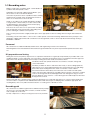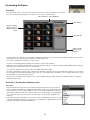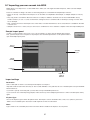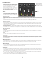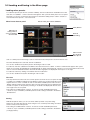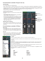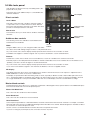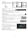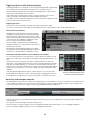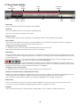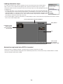
1
2.0.1
Dec 2007
www.fxpansion.com
Contents
.MANUAL
27
2:3 Loading and saving in the Kit page
27
27
• Loading in the Kit page
• Saving in the Kit page
28
2:4 Loading and saving kits
• Loading kits – overview
• Controls in the kit chooser panel
• Saving kits 6
chapter 01: INTRODUCING BFD2
28
28
30
6
1:1 An introduction to BFD2
31
2:5 Kit display and kit-piece slot windows
6
6
• Welcome to BFD2
• Credits
31
32
• Kit display
• Kit-Piece Slot windows
7
1:2 BFD2 Architecture
33
2:6 Loading Kit-Pieces
7
7
8
8
10
33
33
36
36
11
1:3 Recording notes
37
2:7 Importing your own sounds into BFD2
11
11
11
12
13
1:4 Introduction to the BFD2 interface
37
37
38
38
38
38
13
14
• Control conventions
• Interface overview
39
2:8 Kit page toolbar
14
1:5 Control bar
14
14
15
15
15
15
39
39
39
39
40
2:9 Kit-piece inspector
16
1:6 Status Bar
16
16
16
16
16
16
17
17
17
18
18
18
18
18
40
40
40
41
42
42
43
43
45
2:10 Mini-mixer 45
45
45
45
46
2:11 MIDI Note Learn wizard
46
47
47
• Initializing the MIDI learn wizard
• Next slot mode
• Wait mode 19
1:7 Loading BFD2 Presets
21
1:8 Saving BFD2 Presets
48
chapter 03: MIXER PAGE
engineering your drum sound
21
• Elements saved with Presets
22
1:9 BFD2 Help functions
48
3:1 Mixer page overview
22
22
22
23
48
• How to approach mixing
49
3:2 Loading and Saving in the Mixer page
24
chapter 02: KIT PAGE
building and adjusting your kit
49
51
51
51
51
52
3:3 Introduction to BFD2 mixer channels
24
2:1 Kit page overview
25
2:2 Kit Size
52
52
• Channel views
• Types of channel strips in BFD2
25
25
26
26
• • • • • • • • • • • • • • • • • • • • • • • • • • • • • • • • • • • • • How BFD2 works
Anatomy of a kit-piece
Articulations
Mic channels
Microphone buses
Personnel
Kit preparation and tuning
Recording path
Microphones
Page buttons
Preset indicator
Load menu
Save menu
Gain
Help menu
MIDI Log
Audio stream indicator
MIDI stream indicator
RAM indicator
CPU and hard disk performance meters
Offline switch
Controller learn
Context info display
Transport
Rude Solo light
Beat light
Tempo
Time signature
Playback position
Context info display
Tool-tips
Help menu
Getting further help with BFD2
10-piece kit
18-piece kit
32-piece kit
Switching kit sizes
• • • • • • • • • • • • • • • • • • • • • • • • • • • • • • • Overview
Controls in the kit-piece chooser panel
Possible problems when loading
Building unorthodox kits
Sample Import panel
Import settings
Photo settings
Velocity layers
Import & Cancel
Progress bar
Select
Link
Note Learn
Clear Kit
Photo & star rating
Kit-piece quick-load controls
Kit-piece presets
Basic kit-piece controls
Ambience sends
Advanced kit-piece controls
Kit-piece bleed controls
Articulation controls Mixer
Master Dynamics
Master Tuning
Humanize
Loading mixer presets
Saving Mixer presets Varying channels between mixer presets
Loading/saving channel presets Loading/saving effect presets 3:4 Mixer toolbar and utility panel
81
5:3 Loading Grooves
55
55
55
55
55
56
81
• Using the Groove chooser panel to load Grooves
83
5:4 Playing Grooves in the Palette
83
84
84
• Triggering Grooves with MIDI notes
• Triggering Grooves with Preview buttons
• Auto-Play and transport controls
57
3:5 Mixer channel controls and indicators
85
5:5 Working with Grooves in the Palette
57
59
59
• Controls/indicators in Regular and FX/Sends views
• Controls/indicators available in Regular view only
• Controls/indicators available in FX/Send view only
61
3:6 Using the mixer
85
85
86
86
61
61
61
62
62
63
87
5:6 Groove Actions
88
88
89
89
90
5:7 Importing BFD 1.x Grooves and MIDI files
90
91
91
• Importing BFD 1.x Grooves and Bundles
• Importing MIDI files into the Palette
• MIDI Import panel
92
5:8 Groove and Palette Info Inspectors
92
92
92
93
94
5:9 Saving and exporting Grooves
94
94
95
• Saving Grooves
• Exporting Grooves as MIDI
• Export Groove as Audio
96
5:10 Saving Palettes
97
chapter 06: GROOVES PAGE part 2
editing, recording and groove FX
97
6:1 Introduction to the Editor
97
97
98
• Editor interface overview
• Other topics covered in this chapter
• Playing the currently selected Groove
99
6:2 Editor Grid
99
100
100
101
101
102
103
6:3 Grooves toolbar
103
103
103
103
104
104
104
104
105
6:4 Other Editor functions
6:5 Combining elements of other Grooves
55
• • • • • • • • • • • • Reset Mixer
Add Aux
Remove Aux
FX Power
Mixer view switches
Utility Panel Selecting channels
Rearranging channels on the mixer
Channel processing order
Keyboard shortcuts for mixer operation
Channel context menu
Signal Routing indicators
64
3:7 Using FX
64
64
65
65
66
3:8 Using Sends and Sidechains 66
66
67
67
68
3:9 Mic tools panel
68
68
68
• Direct controls
• Ambience bus controls
• Master bleed controls
69
3:10 Mixer preset panel
70
3:11 Audio Export panel 72
chapter 04: GROOVES PAGE - overview
an introduction to BFD2’s groove engine
72
4:1 Introduction 72
72
• Key concepts
• BFD 1.x users
73
4:2 Grooves page interface
74
4:3 Loading and saving in the Groove page
75
4:4 Undo function
75
4:5 Transport, tempo and time signature
75
76
76
76
76
76
4:6 Using the Groove Engine
77
chapter 05: GROOVES PAGE part 1
palettes, grooves and fills
77
5:1 An Introduction to the Palette
77
77
• MIDI channels and key ranges
• Palette and info inspectors visibility
105
105
105
105
106
106
78
5:2 Loading Palettes
107
78
80
• Palette chooser
• Loading BFD 1.0 and 1.5 Bundles
• • • • • • • • • • • • • The FX rack
Basic FX controls
Managing FX with the Effect context menu
Swapping and copying FX between slots
Sends panel
Send indicators
Using sends for parallel processing
Using Sidechaining
Transport
Beat light
Tempo
Time signature
Playback position
• • • • • • • • • • • • • • • • • • • • • • • • • • • • • • • • Selecting Grooves
Operations on Grooves in the Palette
Blending elements of other Grooves in the editor
Slot context menu
Summary of available Groove Actions
Start Actions for Grooves and Fills
End Actions for Grooves
Slot End Actions for Fills
Documenting Grooves and Palettes
Palette and Info inspector visibility
Groove Info Inspector
Palette Info inspector Kit-piece and Articulation lanes
Events
Ruler and Groove length
Velocity lane
View controls
Zoom and scroll controls
Left and right mouse button tools
Hearing events during editing
Select tool
Draw tool
Erase tool
Mute tool
Velocity tool
Undo button
Editor display settings
Metronome Grid controls
Grid-based destructive processes
Edit menu Keyboard shortcuts
108
6:6 Recording Grooves via MIDI
125
8:4 Key mapping view
108
108
108
108
108
109
6:7 Groove FX panel
109
109
109
109
110
110
110
110
111
111
111
111
125
125
125
125
126
127
127
127
127
128
8:5 Working with the key mapper
128
128
129
129
130
8:6 Mapping inspector
112
chapter 07: GROOVES PAGE part 3
auto-play, drum track and other ways of
using grooves
130
130
130
130
130
131
8:7 Introduction to BFD2 automation
112
7:1 Auto-Play mode
112
112
• Auto-Play vs. MIDI triggering
• Auto-Play modes
114
7:2 Drum Track Introduction
114
114
• Enabling the Drum Track
• Drum Track synchronization
131
131
131
131
131
131
131
132
115
7:3 Drum Track display
134
8:8 Mapping MIDI CCs to BFD2 controls
116
7:4 Working with the Drum Track
116
116
117
• Adding parts to the Drum Track
• Manipulating Parts on the Drum Track
• Part context menu
134
134
134
• Automation source table in MIDI CC view
• Mapping indication in BFD2 parameter table
• Mapping an already-mapped BFD2 parameter
135
8:9 Mapping MIDI notes to BFD2 controls
118
7:5 Loading, saving and exporting the Drum Track
118
118
118
• Saving and loading Drum Track contents
• Exporting the Drum track as MIDI
• Exporting the Drum track as audio
135
135
135
135
136
8:10 Mapping host automation to BFD2 controls
118
7:6 Combining playback methods
118
• Groove playback and MIDI triggering of articulations
119
7:7 Using BFD2’s MIDI Out
136
136
136
136
119
119
119
• Setting up the MIDI output function
• Using the MIDI output as a MIDI input in your host
• Latency of the MIDI Out
137
chapter 09: ELECTRONIC DRUMS & BFD2
120
chapter 08: MAPPING PAGE
key and automation mapping
137
9:1 Intoduction to using electronic kits with BFD2
120
8:1 Overview
137
137
137
137
120
120
120
120
138
9:2 Simple hihat control
138
• Advantages and disadvantages of non-variable hihat
control
121
8:2 Loading in the Mapping page
139
9:3 Variable hihat control
121
122
123
123
139
139
140
140
141
124
8:3 Saving in the Mapping page 124
124
124
124
142
9:4 Other settings related to hihat control
142
143
• Preferences
• Kit-piece Inspector
• • • • • • • • • • • • • • • • • • • • • • • • • • • • • MIDI Mappings
Initiating recording
Recording modes
Metronome button
Record lead-in
Show/Hide advanced Groove FX
Groove FX power
Apply: Groove
Apply: All Quantize effect
Double/Half time effect
Simplify effect
Dynamics effect
Swing effect
Humanize effects
Humanize Velocity
Humanize Timing Loading and saving maps
Key mapping view
Automation mapping view
Switching between views
Loading key maps
Key map loaded when BFD2 is launched
Loading Automation maps
Automation map loaded when BFD2 is launched
Save Key Map
Save Automation Map
Save Key + Automation maps
Save MIDI Event Log
• • • • • • • • • • • • • • • • • • • • • • • • • • • • • • • • • • • • • • • • • • • Kit-piece listing
Keyboard layout and keyrange selector
Mapping inspector
Clear all keys
Key labelling
Single-articulation previews
Key context menu
MIDI event log
External MIDI Log
Mapping an articulation to a MIDI key
Mapping multiple articulations to neighbouring keys
Layering multiple articulations on a single key
Special articulations
Articulation list
Low & High velocity
Velocity Curve
Delete articulation
Variable articulation controls
Overview
MIDI CCs and host automation
MIDI note automation
Parameter MIDI learn function in the status bar
Automation mapping page
Multiple mappings
Setting a unique MIDI channel for MIDI automation
Automation view interface
Automation parameters table in MIDI note view
Creating a MIDI note mapping
Mapping indication in BFD2 parameter table
Mapping an already-mapped BFD2 parameter
Automation parameters table in host automation view
Creating a host automation mapping
Mapping indication in BFD2 parameter table
Mapping an already-mapped BFD2 parameter
How electronic drumkits work
Cross-talk between triggers and zones
Double-triggering: setting the Retrigger threshold
Latency
Overview
Assigning variable tip and variable shank articulations
Assigning the hihat height pedal MIDI CC
Customizing hihat pedal response
All Hihats variable setting
144
9:5 Positional snare control
164
chapter 12: MIXING AND EFFECTS USAGE
144
• Variable snare controls
144
9:6 Controlling cymbals
164
164
• Overview
• D.CAM FX
145
chapter 10: BFD2 PREFERENCES
customizing BFD2
165
12:1 Mixing basics
145
10:1 Preferences page overview 165
165
165
166
146
10:2 Data preferences
167
12:2 EQ and filtering
146
146
146
• Preference Options
• Data Path
• Startup
167
167
168
• EQ • Filter
• Filter Mod
147
10:3 Groove preferences
169
12:3 Dynamics processing
147
147
148
149
169
169
170
170
171
150
10:4 Session preferences
150
151
• Session MIDI prefereces
• Session Playback preferences
172
12:4 Distortion
172
173
• Drive
• Bit Crusher 152
10:5 MIDI preferences
152
152
152
153
153
174
12:5 Other effects 154
10:6 Engine preferences
154
155
156
157
174
174
175
175
176
176
176
177
12:6 Mixing each part of the kit
158
10:7 GUI preferences
158
159
159
159
177
177
177
178
178
179
12:7 Routing scenarios
179
160
Chapter 11: PROGRAMMING TIPS
179
179
• Creating sub-mixes for processing mic channels
together
• Mic channel separation
• Creating sends to an external reverb
160
11:1 Building the kit
180
12:8 External processing
160
11:2 Using Velocity layers
160
160
160
• The importance of utilising BFD2’s velocity layers
• Deploying velocity layers effectively
• Dynamics controls
180
180
180
180
161
11:3 Using articulations effectively
161
11:3 Damping, tuning and tightening
161
161
161
• Damping kicks, snares and toms
• Tightening closed hihats
• Tuning the kit
162
11:4 Layering
162
162
162
162
163
11:5 Programming patterns
163
163
163
• Drumming fundamentals
• Transcribe, study and edit existing drum parts
• Physical interfacing with the computer
• • • • • • • • • • • • • • • • • • • • • Show Groove Session preferences
MIDI Import Editor Preferences
Metronome MIDI Channels
MIDI Input Transformations
MIDI display
Key Mapping preferences
MIDI Learn Note Wizard preferences
Streaming Engine
Synth options
Fade preferences
Detail
Control behaviour
Mixer GUI Options
Kit Page
Keyboard Shortcuts
• • • • • • • • • • • • • • • • • • • • • • • • • Mic channel usage
Panning
Gain levels
Approaching EQ and compression
Common compression parameters
Advanced features in BFD2’s dynamics processors
Comp Chan Comp Bus Noise Gate Gain
Delay
Flanger
Chorus RingMod Frequency shifter TinCanVerb Kicks
Snares
Hihats
Toms
Cymbals
Artificial reverb
Distortion and re-amping
Noise
Resampling and re-sequencing
Introduction to layering
Simple layering using the Link function
Layering individual articulations in the Mapping page
Creative and experimental layering
2.0.1
Dec 2007
manual revision 2
chapter 01
INTRODUCING BFD2
1:1 An introduction to BFD2
Welcome to BFD2
Thank you for purchasing BFD2!
Welcome to the most advanced acoustic drum production environment ever. As you begin to explore the software and manual
you’ll start to realise the sheer power you have at your fingertips.
About this manual
There is a huge amount of functionality in BFD2, so please take the time to study this manual as you delve into the software. We
realise it’s a rather large manual, but it is broken down into fairly easily digestible sections, logically structured for each part of the
software.
Remember to use the PDF bookmarks integrated into the document to make navigation through the manual quick and easy.
Credits
SKoT McDonald
Paul Chana
Steve Baker Andy Simper Angus Hewlett Andreas Schnetzler
Gareth Green Alex Akers
Rus Brockman Mayur Maha Rob Bantin
Rhiannon Bankston-Thomas
Julia Titchfield Project lead, Programming (synthesis engine and mixer)
Programming (kit page, panels and Installer)
Programming (Groove engine)
Programming (effect DSP & circuit modelling)
Programming (adapters, licensing)
Programming (website)
Lead audio engineering, production, editing
Graphic design (interface, 3D modelling)
Graphic design (packaging)
Documentation
Quality assurance engineering
Emre Ramazanoglu
Darrin Mooney Kevin Hay
Ben Ferns
Ryan Sellers Alex Volmer
Session drumming
Session drumming
Assistant audio engineering
Photography and video
Technical support
Technical support
Marketing & Sales
Artist relations & Publicity
Steve Duda & Husky Hoskulds
John Emrich BFD 8BK Audio Content (Electronic)
BFD PER Audio Content (Percussion)
BFD2 Grooves: BFD1 Grooves: Jacques Mathias, Patchen Preston, Mikael Adle, Jessy Schmidt, Derik White, Kevin Hay
Chris Dagley, Mayur Maha
Recorded at AIR Studios Lyndhurst Hall, London
Thanks to all the beta testers, especially Rail Jon Rogut, Robert Sfeir, Ralf Steyrer, Jordan L. Chilcott, Christopher Reis, Oliver
Kauert, Andrew Cordani, Mikael Adle, Murray McDowall and Hiroaki Honshuku!
Additional thanks to Apostrophe, BLT, Cay Tre, Karma, all pizza places in a mile for keeping us caffeinated and fed... to the Foundry, Charlie Wright’s, Bar Music Hall, Pool bar, Bricklayers and every booze emporium in Shoreditch for keeping us sane...
...to all our families and friends.... cheers!
© 2007 FXpansion Audio UK Ltd.
www.fxpansion.com
1:2 BFD2 Architecture
How BFD2 works
Disk-streaming multi-channel sample playback engine
At the heart of BFD2 is a sample playback engine that streams multi-channel audio recordings of drum, hihat, cymbal and percussion instruments – called kit-pieces – being played in various ways, and recorded with multiple sets of microphones.
There is an inherent latency when accessing files on a hard drive. Because of this, BFD2 caches a short segment of the start of
every sound in system memory. Therefore, even though BFD2 can use a lot of RAM, it allows you to use sounds with detail levels
far beyond conventional RAM limitations. Hard disk space is far cheaper than RAM, and will be for the foreseeable future.
Dedicated interface for working with multi-channel acoustic drums
Rather than having to work with a generic sampler interface and sample libraries designed within its limitations, BFD2’s user
interface allows you to work with its hyper-detailed sample library as if you were playing and mixing a real drumkit!
There are functions dedicated to building the custom kit of your dreams in seconds, tuning and damping kit-pieces, and high-end
studio quality mixing tools. It features simple-to-use mapping tools, and dedicated support for electronic drumkit systems. Meanwhile, the flexible Groove engine lets you lay down convincing drum tracks quickly and easily.
Anatomy of a kit-piece
Articulations
A kit-piece is made up of one or more articulations. These were referred to as ‘hit types’ in previous versions of BFD. An articulation is an individual way of playing a percussive instrument such as a drum, cymbal or hihat. For example, hihats feature up to
11 articulations – a pedal-down sound (‘foot-chick’) and tip and shank (edge) sounds when the hihat is closed, fully open and at
three positions in-between.
Good use of multiple articulations allows greater realism than using conventional sample-sets, because of the expressive range
possible on a drumkit.
Velocity layers
Each articulation is made up of a number of audio files, called velocity layers. These audio files are recordings of the articulation
being played at varying intensities from soft to hard. As well as the amplitude (‘loudness’), the timbral response of percussive
instruments varies greatly with playing dynamics.
The high amount of velocity layers in BFD2’s sounds lets you recreate the sound of dynamic drumming, giving convincing results
when using accenting. This is very important in the formation of realistic grooves.
Multi-channel audio files
Each velocity layer is an audio file made up of multiple channels. These are recordings from several sets of microphones used to
capture each kit-piece. Real drum recording situations commonly use multiple mic setups in order to capture a variety of different
elements.
Firstly, a kit-piece may sound different depending on where a mic is placed. Snares sound very different when mic’d from above
compared to from below – a mic placed on top captures the ‘pop’ of the skin being struck, while the crunch and sizzle of the mesh
snare is captured at the bottom. Meanwhile, mics inside kick drums tend to pick up the ‘snap’ or ‘click’ of the beater striking the
drum. The main ‘thud’ and low-end power is captured by a mic outside the kick drum.
Drum recording situations also make use of stereo sets of mics to capture the kit as it sounds as a whole within a space. They
capture the projection of the kit and its reflections within the room much more effectively than individual directional close mics on
various parts of the kit, which sound very dry in comparison.
Articulations
Here is a summary of possible articulations in BFD2. Please note that some kit-pieces do not contain all possible articulations.
Kicks
Hit
No Snare
Snares
Hit
Rim
Sidestick
Drag
Half-edge*
*Half-edge is the skin or head struck
half-way between the centre and
the edge. Most previous BFD libraries
featured a flam instead
Hihats
Pedal
Closed tip
Closed shank
1/4-open tip
1/4-open shank
1/2-open tip
1/2-open shank
3/4-open tip
3/4-open shank
open tip
open shank**
** previous BFD libraries did not include an open shank articulation
To support electronic drums, all tip
and shank hihat articulations can
also be triggered via a MIDI CC and 2
‘virtual articulations’ – variable tip and
variable shank
Toms
Hit
Cymbals
Hit
Bell
Edge
3-articulation cymbals are new in
BFD2
Percussion
Hit
Alt
[more...]***
***Percussion slots, like all slots in
BFD2, can have more than 2 articulations. This allows you to load large,
complex percussion pieces from
the BFD Percussion expansion pack,
which required one of 2 snare slots in
BFD 1.5.
Mic channels
Each velocity layer sample of each Kit-Piece articulation possesses 12 mic channels (3 stereo, 6 mono):
Ambience channels (stereo)
Overhead
The signal from the stereo Overhead mic set, above the kit.
Room
• M/S Room in BFD2
• S tereo room in most previous BFD libraries
The signal from the room mics. BFD2 features an M/S room
mic set. BFD2’s mixing engine decodes each M/S-recorded kit-pieces on the voice level, so you can mix and
match kit-pieces with previous BFD libraries, most of which
feature a stereo Room.
Amb3
• Room2 in BFD2’s library
• PZM in most previous BFD2 libraries
The signal from the third set of ambient mics. The wide,
high placed Room2 mics in BFD2 and PZMs in previous
libraries all tend to sound huge!
Direct mic channels (mono)
Kick In
The signal from the mic inside the kick drum.
Kick Out
The signal from the mic outside the kick drum.
Snare Bottom
The signal from the mic underneath the snare drum.
Snare Top
The signal from the first mic above the snare drum.
Snare Top2
The signal from the second mic above the snare drum.
BFD2’s library is the first to contain this mic channel, which
does not exist in previous BFD libraries.
Multi
The signal from the direct mic for all Kit-Pieces except
kicks and snares. This is usually empty for kicks and snares.
Primary direct and bleed channels
The kick and snare mics are used for all Kit-Pieces, as bleed signals are recorded through them.
A Kit-Piece’s own close mic’d direct signal is known as the primary direct mic channel. For a kick, this is in the Kick In and Out mic
channels, and for a hihat or cymbal, it is in the Multi mic channel.
The Kick In/Out mic channels are the primary direct mic channels for the kick. Bleed from the kick appears in the Snare Bottom/Top mic channels. The Multi mic channel is empty for kicks, except on certain BFD XFL kicks, which feature bleed captured
through the hihat mic.
The Snare Bottom/Top mic channels are the primary direct mic channels for the snare. Bleed from the snare appears in the Kick
In/Out mic channels. The Multi mic channel is empty for snares, except on certain BFD XFL snares, which feature bleed captured
through the hihat mic.
The Multi mic channel is the primary direct mic channel for all other Kit-Pieces, whose bleed appears in the Kick In/Out and Snare
Bottom/Top mic channels.
Bleed is only present in the kick and snare mic channels. Bleed from the other mics is not included, because the levels were too
low and not useful enough to justify the extra RAM and hard disk bandwidth required. In any case, bleed can be, in many cases,
an annoying side-effect of the drum-recording process, which is often minimized during post-processing by using noise gates.
Microphone buses
As well as mic channels, when using BFD you need to be aware of the four microphone buses, which are ‘virtual groups’ of the
mic channels.
Ambience buses
The ambience buses allow you to approach mixing in BFD2 in the same way as a real drumkit recording. Even though BFD2’s kitpieces possess discrete ambience signals, this is impossible to achieve when recording a real drumkit, when any ambient mics
capture the sound of the whole of the kit.
Also, while you can manipulate each kit-piece’s direct mics as channels in the BFD2 mixer, there are too many ambience channels (three channels would be required for each kit-piece) to control each kit-piece’s ambience efficiently.
Therefore, the overhead, room and amb3 signals for all kit-pieces are each organized into groups called the ambience buses.
Please note that you can, in the kit-piece inspector, route the ambience signals to individual Aux channels on the mixer if you
wish. This facility is provided for advanced and experimental mixing applications. If you do this, you can still control the Width of
each ambience type using the Mic Tools panel in the Mixer page’s Utility panel.
Overhead
The Overhead mic channels from all
Kit-Pieces.
Room
The Room mic channels from all KitPieces.
Amb3
The third set of ambient mic channels
from all Kit-Pieces.
Direct bus
There is a fourth mic bus, called the Direct bus, which represents the direct mic channels of all kit-pieces mixed together. This
does not have a dedicated channel on the mixer by default, although you can create one if you wish by adding an Aux channel
and routing all kit-pieces’ direct channels to it.
You can, however, control the level of the Direct Master bus using the Direct fader in the Kit page’s Mini-mixer section, or using
the Direct Master level control in the Mixer page’s Mic Tools panel.
How mic buses are used in BFD2
Mic buses are controlled via the Mic Tools panel, part of the mixer’s Utility panel. In this panel, you can control the level of the
Direct bus, as well as the Width and Distance of the ambience buses.
The ambience channels that exist in the Kit page’s Mini-mixer and in the main Mixer page should not be considered as mic buses.
This is because while ambience signals from individual kit-pieces can be routed to other aux channels, they are still considered
to be part of the ambience buses. They are still affected by the Width parameters in the Mic Tools panel, although for technical
reasons the Distance controls do not apply.
10
1:3 Recording notes
BFD2’s sounds were recorded in studio 1 at AIR Studios at
Lyndhurst Hall, Hampstead, London.
AIR Studios was started in 1969 by George Martin, a producer famous for his work with The Beatles.
It moved to its present location at Lyndhurst Hall, a stunning
grade II listed converted church in Hampstead, in 1991. It
offers one of the best live rooms in the UK.
Studio 1’s recording room could be described as medium
to large sized. It consists mainly of wooden surfaces with
excellent dispersion characteristics and a fast decaying
‘explosive’ sounding reverb quality.
The size of the room offers a lot of options when recording,
with very different reverb characteristics depending on the
position and height of ambience microphones.
This room was portioned into a slightly smaller space more appropriate for drum recording, without losing its lush reverberant
sound.
The mixing console in the studio 1 control room is a rather special custom Neve featuring ‘AIR Montserrat’ mic preamps. It was
designed in 1989 by Rupert Neve with consultation from George Martin, and is a classic fully-discrete Neve design offering a
bandwidth of 100 kHz.
Personnel
All sounds were recorded and edited by Gareth Green, with engineering assistance from Kevin Hay.
Drumming duties were shared between Emre Ramazonoglu and Darrin Mooney, both respected and experienced session players.
Kit preparation and tuning
During the sessions, the primary objective was to capture the instruments as organically and powerfully as possible, while covering different kinds of voicing and tuning. A lot of the drums, especially the vintage kits, have loose hardware and other supposed
flaws. These have all been retained, as there really is nothing worse than sterile, characterless drums.
The drums, hihats and cymbals themselves are a mixture of modern, vintage and
custom instruments.
The library includes two historic and famous kits. Firstly, a classic Ludwig ‘Spiral’ Vistalite that was once owned and played by the late John Bonham and, secondly, Ringo
Starr’s Blue Oyster Ludwig kit that was used on a number of classic albums.
The other instruments in the library were selected to offer a wide tonal and stylistic
range, from the modern, tight punch of the DW Collector’s Series to the warm, rounded
tones of the vintage Gretsch Round-badge kit. We even managed to drag our ‘house
kit’ at FX HQ down to the sessions – a late 70s Rogers XP-8 with Bosphorus hihat and
Brady jarrah wood snare.
Snares especially were carefully tuned to range from deep and loose to tight and ringy with lots of overtones. Drum heads were
chosen in order to complement each individual instrument, while various types of damping were used when appropriate. The
resulting library offers a very wide and varied selection of sounds, great for all kinds of music.
Recording path
All sounds were recorded through the Neve’s AIR Montserrat preamps
into Pro Tools, via Prism ADA-8 XR converters, at 24-bit resolution
with a sample rate of 44.1 kHz.
No EQ, compression or other processing was used on any channels.
11
Microphones
Several microphones were set up for many mic positions, with the most appropriate sets being used for each kit.
Some snares were mic’d using a slightly different technique involving the top snare mics pointing at the side of the snare shell
instead of at the top skin.
BFD2’s snares offer two mics for the top snare position, allowing even more flexibility than before when mixing.
Microphone delay was edited out from the direct channels so all kick and snare mic channels are time-aligned with reference to
themselves.
Bottom snare and outside kick mic channels have been phase-flipped to ensure they are already in phase.
No time-aligning of ambience channels was performed, as this would affect the natural stereo image provided by their timing
discrepancies.
Directs
Kick In
The most appropriate inside mic from the following was chosen for each
kick:
• AKG D112 on the beater side
• ElectroVoice RE20 inside the kick
Kick Out
AKG D112
ElectroVoice RE20
Neumann FET 47
CAD VX2
Shure SM57
Neumann KM84
Sennheiser MD421
Coles 4038
Manley Gold
AKG C12
The most appropriate outside mic from the following was chosen for each
kick:
• Neumann FET 47
• CAD VX2
Snare Top
Snare Top1:
Snare Top2:
Shure SM57
Neumann KM84
Snare Bottom
Neumann KM84
Hi Hats
Neumann KM84
Toms
Sennheiser MD421 on top skin only
Cymbals
Neumann KM84
Overheads
The most appropriate set from the following was chosen for each kit-piece:
• Coles 4038
• Manley Gold reference
Sony C800
Both sets were arranged as stereo spaced pairs, with the Coles in a Blumlein array as they have a ‘figure of 8’ response.
Room
For the first Room mic set, original AKG C12s were used in M/S configuration. They were placed in front of the kit, approx. 8 ft.
away and aligned just above the kick drum.
The use of the M/S configuration is intended to facilitate a good true mono room sound, something which is heard in many classic
drum sounds.
It also has the benefit of being used for widening the stereo image.
The BFD2 mixing engine handles the M/S decoding in real-time on the voice level to take advantage of this type of recording.
Amb3 (Room2)
For the Room2 mic set on the Amb3 mic bus, a stereo spaced pair of Sony C800’s was used, placed diagonally 23 ft away from
the kit and very high up in the room – around 20-25 ft.
Compared to the Room set, this mic set has a more obvious room ‘slap back’ reverb effect. Because of the height of placement, it
captures the size of the room well. It has a brighter, more dense sound.
12
1:4 Introduction to the BFD2 interface
Control conventions
Faders
Faders are controlled by clicking and dragging vertically.
Faders are oriented vertically but some controls, such as the send level controls in the FX/Sends mixer view, are
horizontally aligned but are still controlled by clicking and dragging vertically.
Vertical fader movement
Knobs
Knobs are controlled by clicking and dragging vertically (up/down) by default. This can be changed to circular motion in the GUI preferences or with the startup wizard.
Vertical knob movement
Graphs
Graphs can be oriented horizontally or vertically. They can be adjusted in 2 ways:
Jumping to a graph value
• Click anywhere over the range to jump to a value.
• Hover the mouse near the current value and click and drag in the axis in which the
graph is oriented (horizontally or vertically). This method is much like using the graph
a fader.
as
Adjusting with click and drag
Fine control and returning to default values • Holding down the SHIFT key while adjusting a knob, fader or graph gives you fine control.
• Double-click a knob, fader or graph to return it to its default value.
Click to display the menu
Drop-down menus
These are indicated by a downward-facing triangle – click to display the menu.
Click a menu item to select it and hide the menu again, or click elsewhere to just hide the menu.
Other drop-down menus do exist, located on buttons for example. These are detailed in the
manual where necessary.
Click any item to select it
Numerical value boxes
These can be adjusted in 2 ways:
• click and drag vertically to adjust the current value.
Click and drag vertically
to adjust
• double-click the box, type a new value and press ENTER or RETURN.
Double-click to type a value
Right-clicking
Right-clicks are used in several parts of the BFD2 interface, particularly for accessing context menus and the secondary tool in
the Groove editing environment.
If you use a Mac and do not have access to a 2-button mouse, you can access right-click functions by holding down the CTRL
key while clicking your mouse button. However, a 2-button mouse is highly recommended!
Some keyboard shortcut that operate with the CTRL key on Windows are accessed on Mac by using the COMMAND key instead.
This is also known as the APPLE key.
13
Interface overview
Page buttons:
These change
the contents of
the main interface.
Control bar:
Features the Load,
Save and Help
menus, the Page
buttons and other
functions.
See section 1:5.
See section 1:5.
Main interface:
This changes
according to
the currently
selected page.
Status bar:
Contains various
displays and readouts, and several
important functional controls.
See section 1:6.
1:5 Control bar
Save
menu
Page buttons
Preset
indicator
Load
menu
Help
menu
Gain
Page buttons
Clicking these large buttons switches to one of the five Pages, each covering a different aspect of BFD2’s operation. Only one
Page can be active at any one time.
Kit page – chapter 2
The Kit page is used for building and tweaking the kit, as well as providing very simple mixing functions.
Mixer page – chapters 3 and 12
BFD2’s advanced and full-featured mixer gives you access to virtually unlimited routing, mixing and effects
processing. The built-in EQ, compression and other effects can be accessed here, as well as advanced mic manipulation and audio export functions. If you’re more of a writer than an engineer, a variety of professional mixer
presets are at your fingertips.
Grooves page – chapters 4, 5, 6 and 7
The Grooves page is an advanced drum sequencing environment allowing you to preview, load and play BFD2’s
library of ready-made Grooves. It also includes an advanced Groove editor, humanization effects and a number
of ways of varying Grooves over time, such as the Drum Track, which allows you to sequence a whole track of
individual Grooves.
Mapping page – chapters 8 and 9
BFD2 features powerful mapping for playing its drum sounds and automating its parameters.
Preferences page – chapter 10
The Preferences Page allows you to customize BFD2 to your needs by changing a number of settings.
Preset indicator
The Preset indicator displays the name of the last loaded BFD2 Preset. You can also click it to manually
type a new name for the current session, which is also used as the suggested filename when you next
save a BFD2 Preset.
14
Load menu
Clicking the Load button shows a menu allowing you to load various elements into BFD2. The Load menu is partly contextdependent, varying according to whichever Page is currently in view. The menu has 3 sections:
1. BFD2 Preset
A Preset is a snapshot of the entire state of BFD. The Preset loader panel allows you to selectively load different elements of
Presets. For a full guide to loading Presets, please see the ‘Loading presets’ section later in this chapter.
2. Page-dependent elements
Depending on which Page is currently in view, the next part of the menu shows the relevant Load items – the exception is the
Preferences Page, which does not require any loading functions.
3. Commonly used elements
The next section of the menu allows you to load commonly needed elements from Pages other than that currently in view.
The Load menu allows you to load the following elements into BFD2:
• BFD2 presets
• Kits
• Mixer presets
• Palettes
• Grooves
• MIDI keymap
• Automation map – MIDI CC, note and host automation assignments
Save menu
Click the Save button in order to display the Save menu. The save menu is structured in exactly the same way as the Load
menu.
The menu allows you to save the following:
• BFD2 preset
• Kit
• Kit-piece preset
• Mixer preset
• Groove
• Groove Palette
• MIDI keymap
• Automation map – MIDI CC, note and host automation assignments
• Keymap + Automation map
• MIDI event log contents
Groove engine export functions
When in the Groove page, the save menu also gives you access to the groove engine’s export functions.
• Export Groove MIDI
• Export Groove Audio
• Export Track MIDI
• Export Track Audio
Gain
Because it is possible to route audio out of 32 channels when running as a plugin within a host, BFD2 includes an overall
plugin gain control which affects the level of all channels simultaneously.
Do not confuse this control with the Master channel level – the Master channel in the BFD2 mixer is simply a special Aux channel
to which all channels are routed by default, set to outputs 1 & 2 – is all you need if you want to process all BFD2 sounds with the
internal FX and simply output a stereo pair. If this is all that you need, you can use the Master channel level to control the overall
volume of BFD2.
If, on the other hand, you set up more than a stereo output, you can use the Gain control to adjust the volume of all BFD2’s channels together.
Help menu
See section 1:9 for details of the Help menu.
15
1:6 Status Bar
CPU & HD
RAM
performance Controller
indicator
meters
learn
MIDI
Log
MIDI & audio
stream
indicators
Offline
switch
Rude
solo light
Context info
display
Transport
controls
Tempo
Beat light
Playback
position
Time
signature
MIDI Log
Clicking this button opens an external MIDI log window, making it easy to view and troubleshoot incoming MIDI events. The
contents of the log are identical to the smaller log built into the Keymap page.
See section 8:4 for more details of MIDI logging in BFD2.
Audio stream indicator
The Audio stream indicator lights up when BFD2 has successfully launched and been integrated into the host audio engine
(when running as a plugin) or when the standalone version of BFD2 has successfully established communication with the
specified audio device.
MIDI stream indicator
This indicator lights up whenever BFD2 receives any MIDI input.
RAM indicator
This indicator displays how much RAM is being used by BFD2. This includes the cached start portion of each sound,
plus a small overhead for BFD2’s engine.
CPU and hard disk performance meters
Synthesis CPU
Mixer CPU
Hard disk load
The 3 horizontal meters in the status bar provide a performance guage for several aspects of BFD2’s system resource
usage.
Synthesis engine CPU usage
The synthesis engine is involved in receiving MIDI input or generating Groove engine events and playing back the relevant articulations.
Mixer engine CPU usage
The mixer engine processes all routing, mixing and FX functions in BFD2.
Hard disk load
This meter indicates the intensity of hard disk resource usage. Do not be alarmed if this meter reaches high values, as your
machine may well be able to handle a large amount of disk usage. It is intended as an indicator of the amount of hard disk activity
that is occurring.
If your machine cannot handle the amount of disk usage required, the side-effects are usually clearly audible – tails may be cut or
intermittent, and audio dropouts or other artifacts may occur.
Offline switch
This switch is intended for use with hosts that provide an offline (non-realtime) bounce or mixdown facility. When the Offline switch is on, BFD2 waits for all data to be properly delivered from the hard disk before allowing the host to continue,
ensuring that sounds are not cut off before their full decay is complete.
Please note that Offline mode is non-realtime, and should only be used during offline mixdown or rendering in your sequencer, if
it even offers this feature. Do not leave the Offline switch enabled during ordinary playback.
If your sequencer only provides realtime bouncing facilities (a good example is Pro Tools), you should leave Offline mode turned
off at all times.
16
Controller learn
The controller learn function gives you a quick method of assigning BFD2 controls to MIDI continuous controllers (MIDI
CCs) and even to MIDI notes, so that you can use physical keys, knobs, faders or other controllers to control BFD2 controls such as knobs, faders and buttons.
Using controller learn
1. When the controller learn button is enabled, an overlay appears on the interface, with all MIDI-controllable parameters highlighted in green.
2. Click the desired automatable control and then do one of the following:
• move the physical knob, fader or other controller to assign a MIDI CC
• play a MIDI key to assign the note – this is especially useful for buttons
3. The assignment is made, and the assigned note or MIDI CC number is overlaid on the control.
Please see section 8:8 for more details on automation of BFD2 parameters.
Controller learn context menu
While you are in controller learn mode, right-click on any assignable control to display
the controller learn context menu.
Clear automation
This function clears the control’s current automation mapping.
If the parameter has not yet been mapped, this function is greyed out on the menu.
Context info display
The context info display provides information about the
control currently under the mouse cursor. Parameter names
and values are shown.
While a control is being adjusted, the context info display remains locked to the parameter until the mouse button is released,
showing the value as it changes.
Transport
The transport controls are used in conjunction with BFD2’s Groove engine. Please see section 4:5
for more details about the transport buttons.
17
Rude Solo light
The Rude Solo indicator is always lit whenever one or more channels are soloed in the BFD2 mixer.
You can ALT-click this light in order to un-solo all channels currently in a solo state.
Beat light
This indicator flashes on every beat when BFD2’s Groove engine is playing.
Tempo
When using BFD2 as a standalone application, you can enter a tempo for the Groove Engine by double-clicking the
Tempo indicator. Simply type a new tempo and hit ENTER.
You can also click and drag this control up and down to adjust the tempo.
When running BFD2 as a plugin, the Tempo indicator is not editable because BFD2 is locked to the host tempo.
Time signature
Similarly to the tempo, you can enter a new time signature either by double-clicking this indicator and typing a new
value, or clicking and dragging each number in the time signature up and down.
Playback position
This readout is an indicator of the current playback position, in bars and beats, of either the host (when using BFD2
as a plugin), the Drum Track or the current Groove.
18
1:7 Loading BFD2 Presets
BFD2 Presets store the entire state of a BFD2 session.
To load a Preset, click the Load button in the Control bar and click on Load BFD2 Preset... from the Load
menu that appears. This opens the Preset chooser panel. Any available preset is displayed with an image
representing its contents.
Delete Preset from database
Sticky button
Preset listing:
click to select or
double-click to
load
Photo &
Star rating
Click to load
the selected
Preset
Click a Preset to select it. A larger photo and rating information is displayed in the Info display to the right.
To load a preset, select it by clicking on it and then click the Load button.
You can also load any preset in the listing by double-clicking it.
View size
This drop-down menu selects the size of Preset images shown in the chooser panel listing.
A range of settings are available, including text-only displays. Larger sizes result in larger
photos but requires more use of the scrollbars in order to view all the available Presets.
The ‘List’ and ‘Details’ settings result in faster operation due to the fact that images are not
displayed. You can still see a photo for the Preset by selecting it – its details are displayed on
the right side of the panel.
This setting is recalled between sessions. Its state is stored in the BFD2 preferences
– therefore, if you re-initialize your BFD2 preferences this setting is returned to the default
‘Standard’ size.
Sorting
With this drop-down menu you can sort Presets either by ‘Name’ or ‘Star rating’.
Rating the Presets in the database and sorting the listing by ‘Star rating’ can make it easier
to find your favourite Presets.
This setting is recalled between sessions. Its state is stored in the BFD2 preferences
– therefore, if you re-initialize your BFD2 preferences this setting is returned to the default
(sorting by ‘Name’).
Search
The Preset chooser panel includes a search facility in order to narrow down the amount
of Presets shown in the listing.
Delete Preset from database
Clicking this button removes the selected preset from the BFD2 database. This feature is provided if you find you have
too many presets and you want to get rid of those which may not be to your taste, making those you do like easier to
find in the Preset chooser. You are asked for confirmation before you can continue.
If you choose to remove a user preset from the database, you are also asked if you want to remove the preset files from disk – if
19
you click ‘Yes’, the preset file and its associated photo are deleted from the <user location>/BFD2/Presets folder. If you click ‘No’,
the preset’s files remain untouched. If you leave user kit files on disk, they are scanned during the next full rescan of the database
(Trash and rebuild all databases in the BFD2 Data preferences).
BFD2 never prompts to delete factory-installed Preset files.
Note that this function always leaves the actual kit-piece audio files untouched – if you want to delete these to recoup hard disk
space, you must go into BFD2’s audio folder and delete the relevant folders.
Sticky button Enabling the Sticky button results in the Preset chooser panel remaining open after a Preset is loaded.
This is useful if, for example, BFD2 is being played via MIDI and you want to repeatedly change Presets until you find
what you need. Clicking the Sticky button saves you having to keep opening the Preset chooser panel.
Load selective elements from Presets
A BFD2 Preset stores all of the following constituent elements:
• Kit (kit-pieces and kit-piece setups)
• Mixer
• Groove Palette, Drum Track and other Groove page settings
• MIDI keymap
• Automation map – MIDI CC, note and host automation assignments
• Session preferences
A button is provided for each of these elements in the Preset chooser panel, with the exception of embedded Session preferences. Each of these buttons, when enabled, tells BFD2 to load that constituent element of the preset. If an element’s button is
disabled, it is not loaded from the preset.
For example, if you’re working in a session with the Grooves that you want, but you merely want to try out different kit and mixer
settings from various Presets, simply disable the Grooves button – the current Palette in the Grooves page is unaffected when the
new kit and mixer settings are loaded.
By default, the MIDI Map and MIDI CCs buttons are disabled, because you would normally want to stick with the same MIDI mappings when trying Presets.
Load BFD1
Original BFD 1.x Programs are very different types of files to the Preset files used in BFD2. Because of this
they are not shown in the Preset chooser panel, even if you have specified a BFD data path containing valid
BFD 1.x Programs files.
However, BFD2 gives you the ability to load a BFD program file through an additional file load dialog. To do this, click the Load
BFD1 button to bring up a system file open dialog. Then browse to and select the BFD1 program file that you want to import.
After the program file has been loaded in this way, it is recommended that you re-save it as a BFD2 Preset, in order to be able to
load it easily from the Preset chooser panel.
Load / Cancel buttons
To load the currently selected preset, click the Load button.
You can also load any preset by double-clicking it in the listing.
If you change your mind and decide you don’t want to load a new preset, click the Cancel button.
Keyboard operation
You can navigate around the available presets with the cursor (arrow) keys.
The selected preset can be deleted from the database by pressing the DELETE key.
Load the selected preset by pressing the RETURN or ENTER key.
To exit the Preset chooser panel without loading anything, press the ESC key.
20
Photo & Rating
The large photo of the Preset, showing a representation of the included kit-pieces, is especially useful when using ‘List’ or ‘Details’ View settings.
Above the photo is the star rating control, with which you can rate the preset by clicking on
one of the stars. This is used as a ‘favourites’ system when the Sorting type is set to ‘Star
rating’: Presets are shown in order of their rating. This means that those with a higher rating
are shown first.
When you set a preset’s Star rating, it is applied immediately to the BFD2 database.
1:8 Saving BFD2 Presets
To save the current state of BFD2 as a Preset, use the Save BFD2 Preset function on the Control bar Save menu.
A system file save dialog is displayed, prompting you to save the Preset to disk.
The suggested filename used for the Preset is that defined in the Preset name
box, although you can type a new filename if you wish.
When you are happy with the filename and location, hit ENTER or click the Save
button.
Save location
When you save your own Presets, you are prompted by default to save them in
the user level BFD2 folder as follows:
<user location>/Presets
It is recommended that you stick to this location, so that your Presets are accessible whenever you use the Preset chooser.
Wherever you save the Preset, it is added to the BFD2 database. It is very important to remember, however, that if it is removed
from the database (or if you trash and rebuild your database), items not saved in the user location are not re-scanned.
Preset photo
When you save a Preset, a TGA graphic file is saved along with it, showing images of the kit-pieces it contains. This photo is then
visible in the Preset chooser panel during future browsing.
Elements saved with Presets
When you save a Preset, all the following elements are saved with it:
• Kit (kit-pieces and kit-piece setups)
• Mixer
• Groove Palette, Drum Track and other Groove page settings
• MIDI keymap
• Automation map – MIDI CC, note and host automation assignments
• Session preferences
It is not possible to opt not to save any of these elements. You can, however, selectively choose to load only certain elements
(with the exception of embedded Session preferences) when recalling Presets at a later time.
If you specifically do not want to save certain elements, for example Grooves or mixer FX, within a Preset, you should first clear
the Palette or remove the FX from the mixer before saving the Preset.
Alternatively, you may want to save a Preset with mixer settings but no kit-pieces, so that you can load whatever kit-pieces you
want into a certain mixer setup. Since mixer channels are dependent on kit-pieces being loaded, it is necessary to first create the
mixer settings with kit-pieces loaded. However, before saving the Preset, clear the kit (remove all kit-pieces from their slots). The
mixer channels remain, but they are inactive until you load kit-pieces into the relevant slots.
21
1:9 BFD2 Help functions
BFD2 offers a number of different help methods to make learning the software as painless as possible.
Context info display
The context info display in the BFD2 Status bar shows information about the control element currently underneath the mouse
cursor.
This also displays the current values of controls, and updates to show any adjustments made while they are adjusted.
Tool-tips
Tool-tips are shown when the mouse is hovered over a control for a definable length of time. This time is set in the BFD2 GUI
preferences, and is defined in animation frames. A setting of 25 is roughly equivalent to 1 second.
If you prefer, you can switch off tool-tips in the BFD2 GUI preferences.
Help menu
Clicking the Help button on the BFD Control bar displays the Help menu.
Launch PDF Manual
This function launches the BFD2 PDF manual in your system’s PDF reader.
Start BFD2 setup wizard
The BFD2 setup wizard is provided as an easy way to set up BFD2’s preferences in order to achieve the best performance for your particular system.
When you use the Start BFD2 setup wizard function on the Help menu, the
setup wizard panel is displayed.
Amplitude scaled response
This item affects Vel to Amp default amount setting in the BFD2 Engine preferences. With an amplitude-scaled response, the
default Vel to Amp amount is set at 50%, meaning that whenever a kit-piece is initialized – in other words, when it has just been
cleared – the Vel to Amp amount is set to 50%. Therefore, when you subsequently load a kit-piece, it is fully amplitude-scaled with
incoming velocity.
If you un-tick this checkbox, the default Vel to Amp amount is set at 0%: no amplitude scaling is applied when a slot is initialized.
If you want to specify other values for the Vel to Amp default amount preference, it is necessary to adjust the preference itself.
This computer is connected to the internet
Ticking this checkbox enables the Launch web browser for images setting in the BFD2 GUI options. This results in launching factory Groove Palette and mixer preset authors’ websites when their images are clicked on the BFD2 interface.
I have BFD 1.x installed
If this checkbox is ticked, BFD2 adds your BFD
1.x data path and imports all the kits into the
BFD2 database. If BFD2 detects a BFD1 installation on your system, this checkbox is ticked by
default.
I like to use tool-tips
Ticking this checkbox results in tool-tips being
displayed when the mouse cursor is held over a
control for approx. 1 second. If you want to adjust the time it takes for tool-tips to appear, you
must edit the Tool-tip appear time setting directly
in the BFD2 GUI preferences.
22
When moving a control I like to drag... [up and down / around (circular)]
Setting this item to ‘up and down’ requires vertical mouse movement to adjust circular knobs in BFD2, while setting it to ‘around
(circular)’ requires circular mouse movement. The preference that this item affects – Circular knob movement – is located in the
BFD2 GUI preferences.
My main host application is... [BFD2 Standalone / various plugin hosts]
This item affects the -2 octave numbering and -1 octave numbering settings in the BFD2 GUI preferences. If you select the BFD2
standalone here, the -2 octave system of note numbering is used. If you choose one of the other hosts in the list, the note numbering preferences are set accordingly.
I am a... [keyboard/finger drummer / e-drummer / drum programmer]
I use a... [various MIDI controller hardware keymaps]
These items in the wizard specify how you are going to control BFD2. Depending on the setting specified for the first item, a
number of hardware controller keymaps are listed in the second item.
Note that BFD2 overrides this setting if you subsequently load a new keymap, or if you set up a startup Preset with different keymap settings.
Getting further help with BFD2
Further information and help about BFD2 can be found at the fxpansion.com webpage. Internet shortcuts to all of these help
methods are available on the BFD2 Help menu:
1. Launch online FAQ: www.fxpansion.com/bfd2faq
The FAQ is often updated with late-breaking information about BFD2. This includes common solutions to problems which are not
covered in the manual – for example installation and authorization issues.
2. Launch online forum: www.fxpansion.com/forum
Our forum is frequented by our programming and technical support teams, as well as knowledgable and experienced users of
BFD2. If you have a query which is not covered in the provided documentation or webpage FAQs, you can often find an answer
in the forum after a quick search. It is also possible to obtain answers to new questions from other users out of our usual office
hours.
3. Launch online support: www.fxpansion.com/support
If all other help resources have not yielded answers to your questions, you can fill out a technical support request in the Support
section at fxpansion.com.
You must register your copy of BFD2 before you can obtain technical support.
23
chapter 02
KIT PAGE
building and adjusting your kit
2:1 Kit page overview
1
5
6
3
2
7
4
1. Loading and saving kits – 2:3, 2:4
Use the Load and Save menus in order to load and save kits.
2. Kit Size – 2:2
This selector lets you choose between 10, 18 and 32 piece kits.
3. Kit display – 2:5
This changes for each kit size. Click a kit-piece in the display in order to select it. Each kit-piece in the display flashes when it is
played.
4. Kit-piece slots and loading kit-pieces – 2:5, 2:6, 2:7
The number of kit-piece slots shown depends on the kit size. Each slot features a controls for loading a kit-piece into the slot and
clearing its contents, as well as trim and direct pan controls.
5. Kit page toolbar – 2:8, 2:11
The toolbar features tools for selecting and linking kit-pieces.
It also features a wizard tool for easy MIDI learn-based key assignments for kit-piece articulations.
6. Kit-piece inspector – 2:9
This inspector features a multitude of ways to tweak the sound and response of the selected kit-piece and its articulations.
A preset system is also available for kit-piece inspector settings.
The inspector includes the kit-piece quick-load controls, allowing you to flick through available kit-pieces without opening the kitpiece chooser panel.
7. Mini-mixer 2:10
The mini-mixer contains a number of useful functions.
Firstly, the master tune, master dynamics and humanize controls offer a number of ways of changing the way the kit sounds and
plays.
The mini-mixer itself allows a quick way of setting the mix between direct and ambient mic channels without having to switch to
the Mixer page.
24
2:2 Kit Size
You can choose between 3 kit sizes using the selector buttons on the toolbar.
All slots have an intended purpose – when the kit-piece chooser panel is displayed for each slot, it sets the Type and Search
controls to show the intended variety of kit-piece.
However, you can load any kit-piece into any slot by changing the Type and Search criteria.
10-piece kit
1 2 3 4 5 6 7 8 9 10 Kick1
Snare 1
Hihat
Floor Tom
Mid Tom
High Tom
Crash 1
Cymbal 1
Ride 1
Perc
When the load kit-piece button is clicked for the tom slots, the kitpiece chooser defaults to the appropriate type of tom by setting the
search criteria automatically as required. To view all toms, clear the search text-box.
When loading a kit-piece into the cymbal slots, the kit-piece chooser defaults to the intended cymbal type by putting the relevant
search criteria automatically into the search text-box. To view all cymbals, clear the search text-box.
The Cymbal 1 slot (slot 8) chooser defaults to showing all cymbals.
18-piece kit
1
2
3
4
5
6
7
8
9
10 11 12 13 14 15 16 17 18 Kick 1
Snare 1
Hihat
Floor Tom
Mid Tom
High Tom
Crash 1
Cymbal 1
Ride 1
Kick 2
Snare 2
Perc
Tom 4 (all toms)
Tom 5 (all toms)
Tom 6 (all toms)
Crash 2
Cymbal 2
Ride 2
When the load kit-piece button is clicked for the Floor, Mid and High
Tom slots, the kit-piece chooser defaults to the appropriate type of
tom by setting the search criteria automatically as required. To view
all toms, clear the search text-box.
When loading a kit-piece into the Tom 4, Tom 5 and Tom 6 slots, the kit-piece selector defaults to displaying all toms.
When loading a kit-piece into the cymbal slots, the kit-piece chooser defaults to the intended cymbal type by putting the relevant
search criteria automatically into the search text-box. To view all cymbals, clear the search text-box.
The Cymbal 1 and Cymbal 2 slots (slot 8) chooser defaults to showing all cymbals.
25
32-piece kit
1
2
3
4
5
6
7
8
9
Kick 1
Snare 1
Hihat
Floor Tom
Mid Tom
High Tom
Crash 1
Cymbal 1
Ride 1
10 11 12 13 14 15 16 17 18 Kick 2
Snare 2
Perc
Tom 4 (all toms)
Tom 5 (all toms)
Tom 6 (all toms)
Crash 2
Cymbal 2
Ride 2
19 20 21 22 23 24 25 Perc 2
Perc 3
Perc 4
Perc 5
Perc 6
Perc 7
Perc 8
26 27 28 29 30 31 32 Perc 9
Perc 10
Perc 11
Perc 12
Perc 13
Perc 14
Perc 15
The 32-piece kit features the same first 18 slots as the 18-piece kit, but with an extra 14 percussion slots as shown above.
These slots have no default mapping, due to the fact that they potentially need lots of MIDI keys, so it would really be necessary
to first set the Groove Palette to another MIDI channel.
If you need this many kit-pieces, please set up your desired mapping and save a Program so that it’s set up for future use.
While these slots are intended as a percussion rack, especially for use with the BFD Percussion expansion pack, you can of
course use them to load any kit-piece you like.
Switching kit sizes
If the kit size is changed to a larger setting, any currently loaded Kit-pieces are unaffected - you simply have more slots available
to you.
If you change to a smaller kit size, the slots which still exist in the smaller size are unchanged. However, any slots that do not exist
in the smaller size are lost – the kit-pieces and any settings made to the slot are cleared from memory.
For example, if you change from an 18-piece kit to a 10-piece kit, slots 11-18 are discarded.
26
2:3 Loading and saving in the Kit page
Loading in the Kit page
You can load and save a number of different elements in the Kit page:
Kits (section 2:4)
A kit is comprised of a number of kit-pieces loaded into kit-piece slots, as well as any Link setups
and additional parameters for each kit-piece (adjustable in the kit-piece inspector). You can, if you
wish, choose to load only the kit-piece arrangement, and dispense with the additional settings.
Kits are loaded and saved using the Load menu in the BFD2 control bar.
Kit-pieces (section 2:6)
You can load individual kit-pieces into the available
slots in order to build a custom kit.
This is achieved via the Load buttons on each kitpiece slot, or by double-clicking anywhere in a slot.
You can also use the kit-piece quick-load controls at
the top of the kit-piece inspector as an alternative way
of loading kit-pieces.
Kit-piece presets (section 2:9)
These are presets of kit-piece inspector settings for each kit-piece class – kicks, snares,
hihats, toms, cymbals and percussion.
Kit-piece presets are saved using the ‘Save kit-piece preset’ function on the BFD2 Load
menu in the control bar.
You can load kit-piece presets via the kit-piece preset loading controls, located in the kitpiece inspector.
BFD2 Presets (section 1:7) You can also load BFD2 Presets using the Load menu on
the BFD2 Control bar. Presets contain a snapshot of the
entire state of BFD2. In the Preset chooser you can load any or all of the following:
• Kit (kit-pieces and kit-piece setups)
• Mixer
• Groove Palette
• Keymap
• Automation map
• Session preferences
Rather than be able to load default kits, mixer presets, Grooves and mappings when the software is launched, BFD2 instead only
allows you to set up a default Preset to load whenever it is launched. This is to avoid having too many default settings specified,
and also due to the sheer variety of possible kit, mixer and mapping setups that might conflict with each other.
Saving in the Kit page
You can save the following using the Save menu:
Kits: section 2:4
Kit-piece presets: section 2:9
BFD2 Presets: section 1:8
27
2:4 Loading and saving kits
Loading kits – overview
To load a kit, click the Load button in the BFD Control bar and click on Load Kit... from the Load menu that
appears. This opens the kit chooser panel.
Delete kit from database
Sticky button
Kit listing: click to
select or doubleclick to load
Info
Click to load
the selected kit
All available kits are displayed with an image representing its contents. To see more information about a kit, click it to select it.
Detailed information about the kit and a larger photo is displayed in the inspector to the right.
To load a kit, select it by clicking on it and then click the Load button.
You can also double-click any kit in the listing in order to load it.
A kit file stores a set of kit-pieces in either of the 3 available kit sizes, as well as further settings in the Kit page, such as Link and
kit-piece inspector setups.
Controls in the kit chooser panel
Load Audio Only button
You can choose to load only the kit-pieces in a kit by clicking the ‘Load Audio only’ button. Leaving
this button off results in a kit’s Link and kit-piece inspector settings being loaded with it.
Slot Load switches
The Slot Load switches allow you to specify which kit-piece slots are replaced
by new sounds and settings from the loaded Kit.
Turning off a Slot Load switch results in the current contents of that slot remaining unchanged when a kit is loaded.
View size
This drop-down menu selects the size of kit images shown in the chooser panel. A range of
settings are available, including text-only displays. Larger sizes result in larger photos but requires more use of the scrollbars in order to view all the available kits. The ‘List’ and ‘Details’
settings result in faster operation due to the fact that images are not displayed. You can still
see a photo for the kit by selecting it – its details are displayed in the inspector.
This setting is recalled between sessions. Its state is stored in the BFD2 preferences
– therefore, if you re-initialize your BFD2 preferences this setting is returned to the default
‘Standard’ size.
28
Sorting
With this drop-down menu you can sort kits either by name or by star rating.
Rating your favourite kits and sorting chooser contents by Star rating can make it easier to
find your favourite kits.
This setting is recalled between sessions. Its state is stored in the BFD2 preferences
– therefore, if you re-initialize your BFD2 preferences this setting is returned to the default
(sorting by ‘Name’).
Search
The kit chooser panel includes a search facility in order to narrow down the amount of
kits shown in the chooser panel.
Quick-search Useful search terms are stored in the quick-search drop-down menu to the left of the Search text-box.
Delete kit-piece from database
Clicking this button removes the selected kit from the BFD2 database. This feature is provided if you find you have too
many kits and you want to get rid of those which may not be to your taste, making kits you do like easier to find in the
chooser panel. You are asked for confirmation before you can continue.
If you choose to remove a user kit from the database, you are also asked if you want to remove the kit files from disk – if you click
‘Yes’, the kit file and its associated photo are deleted from the <user location>/BFD2/Kits folder. If you click ‘No’, the kit’s files remain untouched. If you leave user kit files on disk, they are scanned during the next full rescan of the database (Trash and rebuild
all databases in the BFD2 Data preferences).
BFD2 never prompts to delete factory-installed kit files.
Note that this function always leaves the actual kit-piece audio files untouched – if you want to delete these to recoup hard disk
space, you must go into BFD2’s audio folder and delete the relevant folders.
Sticky button Enabling the Sticky button results in the kit chooser panel remaining open after a kit is loaded.
This is useful if, for example, BFD2 is playing a sequence or Groove and you want to repeatedly change kits until you find
what you need. Clicking the Sticky button saves you having to keep opening the kit chooser panel.
Load / Cancel buttons
To load the currently selected kit, click the Load button.
You can also load any kit in the listing by double-clicking it.
If you change your mind and decide you don’t want to load a new kit, click the Cancel button.
Keyboard operation
You can navigate around the available kits with the cursor (arrow) keys.
The selected kit can be deleted from the database by pressing the DELETE key.
Load the selected kit by pressing the RETURN or ENTER key.
To exit the chooser panel without loading anything, press the ESC key.
Info
The Info area displays information about the currently selected kit and allows you to rate it.
Photo & rating
The large kit photo shows a representation of the included kit-pieces. It is especially useful if
you are using the ‘List’ or ‘Details’ views.
Above the kit photo is the star rating control, with which you can rate the kit by clicking on
one of the stars. This is used as a ‘favourites’ system when the Sorting type is set to ‘Star
rating’: kits are shown in order of their rating.
When you set a kit’s rating, it is applied immediately to the BFD2 database.
Info
The info display shows information about which kit-pieces exist in each of the kit’s slots.
• Valid kit-pieces’ names are shown in black
• Empty slots or those with unidentifiable contents are shown in grey
29
• Invalid kit-pieces are shown in red – this usually means that the kit-pieces have not been authorized or are somehow corrupt.
If you suspect they are not authorized, exit BFD2 and run the FXpansion License Manager to verify their authorization status.
If necessary, authorize the expansion pack containing the kit-pieces. Then re-run BFD2. It may also be necessary to trash and
rebuild the BFD2 database.
Import BFD1 kit
Original BFD kits are very different types of files to the kit files used in BFD2. Because of this they are not
shown in the kit selector panel, even if you have specified a BFD data path containing kits made for BFD
1.0 or 1.5.
However, BFD2 gives you the ability to import BFD kit files to the BFD2 database. To do this, click the BFD1 Kit Import button
to bring up a system file open dialog. Then browse to and select one or more BFD1 kit files that you want to import. The kits are
converted into BFD2 format and added into the database so that they can be loaded in the kit chooser.
If you specify that you are a BFD1.x user during the BFD2 setup wizard, BFD2 automatically imports any BFD1.x kit files it finds
in the current data paths.
Saving kits
Use the Save Kit... item in the BFD2 Save menu in order to save the current kit.
Clicking this menu item opens a system file save dialog allowing you to save the
kit to any location.
Save location
When you save your own kits, you are prompted by default to save them in the
user level BFD2 folder at the following location:
<user location>/Kits
We recommend that you save your kits into this folder in order for them to be visible in the Kit chooser panel.
Wherever you save the kit, it is added to the BFD2 database. It is very important
to remember, however, that if it is removed from the database and you trash and
rebuild your database, items not saved in the user location are not rescanned.
Kit Photo
When you save a kit, a TGA graphic file is saved along with it, showing images of the kit-pieces it contains. This photo is visible in
the kit chooser panel during future use.
30
2:5 Kit display and kit-piece slot windows
Kit display
Slot windows
Kit display
The kit display serves a number of purposes in the Kit page.
Visual representation of the current kit
The kit shown differs depending on the current kit size. See section 2:2 for details of the 3 kit sizes.
When the mouse cursor is moved over a part of the kit in the display, its corresponding slot window is highlighted (this behaviour
can be turned off in the BFD2 GUI preferences using the Connect kit and slot setting).
Kit-piece event indicators
When a kit-piece receives a MIDI, Groove or preview event, its surface flashes in the kit display to indicate that it has been played.
Kit-piece audition
Click on a kit-piece in the kit-display in order to hear a preview of the main articulation in the kit-piece (hit, or closed tip for hihats)
at a velocity of 95.
In order to preview any articulation at any velocity, use the Audition strip in the kit-piece inspector’s articulation control section.
Selecting a kit-piece
ALT-click on any kit-piece in the kit display in order to select it without auditioning it.
31
Kit-Piece Slot windows
Slot number
Load kit-piece
Image
Selected slot
Trim
Clear
kit-piece
Direct
Pan
Mute &
Solo
Each available kit-piece slot window in the display shares some common features.
Kit Display highlight
When the mouse cursor is moved over any slot window, its corresponding part of the kit display is highlighted.
Selecting a kit-piece
When using the Select tool, clicking on a kit-piece slot selects it, and its settings are displayed in the kit-piece inspector.
If you enable the Select triggers preview setting in the BFD2 GUI preferences, clicking a kit-piece slot window to select it also
results in an audition being heard.
Load kit-piece
The Load button opens the kit-piece chooser panel.
You can also double-click anywhere on the slot in order to open the chooser panel.
See section 2:6 for more details on loading kit-pieces.
Clear kit-piece
This button removes any kit-piece currently loaded into the slot.
Image
The main part of the slot window shows a photo of the loaded kit-piece. If the slot is empty, a generic grey picture of the suggested kit-piece type is shown.
Trim
The trim control is a global volume control for the kit-piece. Adjusting it affects the level of all the kit-piece’s mic channels equally.
You can think of it as a ‘pre’ volume control - it sets the level of the kit-piece at the start of the signal path, before any routing and
mixing features are applied.
This control is duplicated in the kit-piece inspector.
Direct pan
The pan control sets the pan position of the kit-piece within the direct master bus. It does not affect the stereo position of the kitpiece in its ambience channels.
This control is duplicated in the kit-piece inspector, and on the primary direct channel for the kit-piece in the Mixer page.
Mute & Solo
With these buttons, you can mute and solo all mic channels for each kit-piece.
These controls are duplicated in the kit-piece inspector.
Kit-piece audition
When a kit-piece is loaded into the slot, ALT-clicking anywhere in the slot plays an audio preview of the main articulation in the kitpiece (hit, or closed tip for hihats) at a velocity of 95. The Select tool must be enabled in the toolbar for this to occur.
If you need to preview individual articulations at variable velocities, use the Articulation preview controls in the Kit-Piece Inspector.
If you prefer, this audition function can operate in a similar way to the articulation Audition strip, although restricted to the main
articulation only. Enable the Left-right velocity-scaled preview support setting in the BFD2 GUI preferences if you want the audition to work in this way.
32
2:6 Loading Kit-Pieces
Overview
To load a kit-piece into a slot, click the Load button on the slot to open the kit-piece chooser panel.
You can also double-click anywhere on a kit-piece slot in order to open the panel.
Delete kit-piece from database
Sticky button
Kit-piece listing:
click to select or
double-click to
load
Preview & Info
Click to load
the selected
kit-piece
Click on a kit-piece to select it. You can preview individual articulations at any velocity before loading the kit-piece. Once the desired kit-piece is selected, click the Load button to load it into the slot.
You can also double-click a kit-piece in order to load it.
To return to the Kit page without loading a new kit-piece, click the Cancel button.
BFD2 also offers the kit-piece quick-load controls in the kit-piece inspector, for fast browsing through available kit-pieces without
opening the chooser panel. See section 2:9 for details.
You can also load kit-pieces in various ways in the Mixer and Grooves pages.
Each slot is intended for a specific type of kit-piece. By default, the Type drop-down menu and Search criteria are set so that the
chooser panel shows the relevant kit-piece type. If you try to load a kit-piece into the Ride 1 slot for example, Type is set to ‘Cymbal’ and “Ride” is used as the Search criteria.
However, you can load any type of kit-piece into any slot. Simply change the Type and Search settings in order to change the
displayed kit-piece type.
Controls in the kit-piece chooser panel
View size
This drop-down menu selects the size of kit-piece images shown in the chooser panel. A
range of settings are available, including text-only displays. Larger sizes result in larger photos but requires more use of the scrollbars in order to view all the available items. The ‘List’
and ‘Details’ settings result in faster operation due to the fact that images are not displayed.
You can still see a photo for each kit-piece by selecting it – its details are displayed in the
inspector.
This setting is used for all kit-piece slot choosers, and is recalled between sessions. Its state
is stored in the BFD2 preferences – therefore, if you re-initialize your BFD2 preferences this
setting is returned to the default ‘Standard’ size.
33
Sorting
Using this drop-down menu you can sort kit-pieces in the listing by the following criteria:
• Manufacturer
• Star rating
• Articulation count
• Kit-piece class
• Disk size
• Name
Rating your favourite kits and sorting chooser contents by ‘Star rating’ can make it easier to
find your favourite kit-pieces.
This setting is used for all kit-piece slot choosers, and is recalled between sessions. Its state is stored in the BFD2 preferences
– therefore, if you re-initialize your BFD2 preferences this setting is returned to the default (‘Manufacturer’).
Type
This drop-down menu specifies the type of kit-piece displayed in the current kit-piece slot’s
chooser panel.
When a slot’s kit-piece selector panel is opened, only kit-pieces that correspond to the slot’s
intended purpose are displayed. However, by changing the kit-piece type you can load any
kit-piece into any slot.
Please note that there are certain important things to bear in mind when loading different
types of kit-pieces into slots in this way. Please see the ‘Building unorthodox kits’ sub-section
below for usage guidelines.
Search
The kit-piece chooser panel includes a search facility in order to narrow down the
amount of kit-pieces shown in the listing.
Quick-search Useful search terms are stored in the quick-search drop-down menu to the left of the Search text-box.
Delete kit-piece from database
Clicking this button removes the selected kit-piece from the BFD2 database. Please note that the kit-piece’s audio files
remain untouched.
This feature is provided if you find you have too many kit-pieces and you want to get rid of those which may not be to your taste,
making kit-pieces you do like easier to find in the selector. You can bring them back by trashing and rebuilding your database.
Because this function does not affect kit-piece audio files, if you want to reclaim hard disk space, you must go into BFD2’s audio
folder and delete the relevant kit-piece folders.
Sticky button Enabling the Sticky button results in the kit-piece chooser panel remaining open after a kit-piece is loaded.
This is useful if, for example, BFD2 is playing a MIDI sequence or Groove and you want to repeatedly change kit-pieces
until you find what you need. Clicking the Sticky button saves you from having to keep opening the slot’s chooser panel.
Target indicator
The target indicator displays information
about the destination kit-piece slot:
Target Slot (slot number)
Each kit-piece slot is numbered – see section 2:2 for information on kit-piece slot numbering for each of the 3 available kit sizes in
BFD2.
Target Suggested Class
This is the suggested kit-piece type for the destination slot number. Nevertheless you can, as already mentioned, load any type of
kit-piece into any slot.
Currently in Slot
The name of the kit-piece currently loaded into the slot. If no kit-piece is currently loaded into the slot, ‘Empty slot’ is shown.
34
Import
Clicking this button opens the sample import panel. BFD2 allows you to create single-articulation mono or
stereo kit-pieces with multiple velocity layers from a set of one of more samples. See section 2:7 for a full
guide to using this feature.
Load / Cancel buttons
To load the currently selected kit-piece, click the Load button.
You can also double-click any kit-piece in the listing in order to load it.
If you change your mind and decide you don’t want to load a new kit-piece into the slot, click the Cancel button.
Keyboard operation
You can navigate around the available kit-pieces with the cursor (arrow) keys.
The selected kit-piece can be deleted from the database by pressing the DELETE key.
Load the selected kit-piece by pressing the RETURN or ENTER key.
To exit the kit-piece chooser panel without loading anything, press the ESC key.
Preview & Info
The preview and info area displays information about the selected kit-piece, as well as allowing you to rate it and audition its articulations.
Photo/Preview tab
• photo & star rating
The large kit-piece photo is especially useful if you are using the ‘List’ or ‘Details’ views.
Above the photo is the star rating control, with which you can rate the kit-piece by clicking on
one of the stars. This is used as a ‘favourites’ system when the Sorting method is set to ‘Star
rating’: kit-pieces are shown in order of their rating.
Please note that you can also set a kit-piece’s rating when it is loaded, in the kit-piece
Inspector.
Whichever of theses methods you use to rate a kit-piece, the change is applied immediately
to the BFD2 database.
• preview
Each articulation present within the selected kit-piece can be previewed by clicking its Audition strip. Click towards the left of the strip for lower velocity layers, and towards the right for
higher layers.
Info tab
The info tab in the Inspector shows factory information about the selected kit-piece.
Two information readouts are shown: the top display shows standard information regarding
the manufacturer, name, materials and production date of the kit-piece. The class (type) of
the kit-piece, as well as its size on disk and its location in the data path is also shown.
Below this information, a separate text-box contains additional factory and recording notes.
35
Possible problems when loading
If a problem is encountered when loading a kit-piece, an error icon is displayed in the slot. If you
experience any of these, please get in touch with our technical support team for further advice.
Not found
his error appears when BFD2 can’t find a kit-piece that exists in the database in any
T
of the current data paths. You may have deleted or moved some files or folders by accident, or there may be other reasons the data could be missing. If you cannot resolve
the problem, it may help to trash and rebuild the database in the BFD2 Data preferences.
Error
his indicates that something went wrong during the loading process – the main cause of this is if there is not enough
T
RAM to load the kit-piece fully. Other possible causes: some layers may have failed to load or there may have been inadequate permissions to load the kit-piece. The BFD2 runtime log should help in determining what went wrong – please
consult the BFD2 FAQ for details of how to retreive the logs, or contact our tech support team for advice.
Exception
his message signifies a serious internal error when loading the kit-piece. You shouldn’t ever see this message, but if it
T
appears, the BFD2 runtime log should contain information about what happened. See the BFD2 FAQ for details of how to
retrieve it, or consult our tech support team for advice.
Unknown
This means that an unknown error occurred. You shouldn’t ever see this message, but if you do, please save the current
BFD2 session as a Preset and contact our technical support department for further advice.
Building unorthodox kits
Even though each slot in all 3 kit sizes have suggested purposes, BFD2 allows virtually unlimited freedom when building kits. This
is achieved by changing the setting in the Type selector in the kit-piece chooser panels.
Potential issues
While being able to freely build your kit can yield some great creative ideas, you should be aware of these potential issues:
1. Articulation mappings
Because different kit-pieces have different numbers of articulations, you can create discrepancies between the kit and the keymap.
If you load a snare into a tom slot, for instance, the slot contains 5 articulations instead of 1. These extra articulations need to be
keymapped before they can be played via MIDI.
If, on the other hand, you load a tom into a snare slot, any mappings which exist for the snare which do not have a logical equivalent for a tom ‘fall back’ to a suitable available tom articulation.
It is not recommended to load different types of kit-pieces into the Hihat slot. This slot is specially designed to load hihats, and
there is no real reason to load any other type of kit-piece into this slot. If you have an electronic drumkit, you should be aware that
the Hihat slot is the only slot that supports variable hihat control.
2. Grooves
Even though Groove events do not rely on articulations being mapped, they are nevertheless usually intended for a certain type
of kit-piece articulation. In the vast majority of cases, Grooves are designed for kits that follow suggested kit-piece slot uses. However, you may sometimes come across Grooves that come with a BFD2 preset specifically designed for them.
Like articulation mappings, Groove events fall back intelligently to suitable articulations in the loaded kit-piece, so this can be
good for experimentation. Please bear in mind, however, that a Groove simply may not make sense when played with a completely different type of kit composition.
Solution: save BFD2 Presets
Because of the large number of variables when building unconventional kits, it is recommended that after you have set up the kit
and mixer the way you want it, mapped the available articulations as required and so on, you should save a BFD2 Preset using
the Save menu on the BFD2 Control bar. This function saves the entire state of BFD2, and therefore saves all current BFD2 settings.
It is much more convenient to save a BFD2 Preset file instead of having to save Kit, Mixer and MIDI presets that correspond to
one another. When loading BFD2 Presets, you can choose to only load selective elements from those saved in each Preset file,
which are applied to the current BFD2 environment where suitable.
For more details on loading and saving BFD2 Presets, please see sections 1:4 and 1:5.
36
2:7 Importing your own sounds into BFD2
BFD2 allows you to import mono or stereo WAV files to make your own single-articulation kit-pieces, which can have multiple
velocity layers.
There are a number of things to be aware of when using kit-pieces created with the Sample Import function:
• There can be only 1 articulation in the kit-piece. It can be either one amplitude-scaled sample, or multiple samples for velocity
layers.
• They only produce sound in the direct bus. There is no facility for ambience channels such as those within BFD2’s factory
sounds. However, you can of course use the mixer’s routing functions to send the audio for further processing on an aux channel, for example.
• Only 1 channel is active for the kit-piece slot on the mixer, no matter what Kit-Piece slot is used, unless it is loaded into the kick1
or snare1 slots.
• Samples can be mono or stereo, but you cannot use a combination of mono and stereo samples in the same imported kit-piece.
Sample Import panel
In order to create a kit-piece from a set of one or more samples, you must open the Sample Import panel.
First, open the kit-piece chooser panel for any kit-piece slot. Click the Import button on the panel in order to
open the Sample Import panel.
Import
settings
Velocity
layers
Photo
settings
Progress
bar
Import &
cancel
buttons
Import settings
Destination
Select a data path to which to save the imported samples as a kit-piece.
Imported sounds stream in the same way as other sounds in BFD2, so the path must be one of the data paths set up in the BFD2
Data Preferences.
If you want to specify a new data path, you must first set it up in the BFD2 preferences.
If you receive an error when importing samples, make sure that you have adequate permissions to write to the data path, and try
again.
Kit-piece Type
Choose the kit-piece type from this drop-down menu. The kit-piece can be classified as kick, snare, tom, cymbal or percussion.
‘Hihat’ is not an available option because it would require more than one articulation.
Name
Type a name for the created kit-piece. This is the name which is visible in the kit-piece chooser panels.
37
Photo settings
You can specify any JPEG, PNG or TGA image file as a photo to associate with the kit-piece. If no image is specified, a default
image is used.
Browse button
Clicking the browse button opens a system file open dialog allowing you to browse to a JPEG, PNG or TGA file to specify as the
imported kit-piece’s photo. The file must have a resolution of 180x150 pixels.
Clear button
Clicking this button removes the photo currently specified for the kit-piece.
Velocity layers
This is where you add samples, and sort them into the desired order, going from the highest velocity layer at the top of the list, to
the lowest layer at the bottom.
Add Layer(s)
Click this button to add a sample. Any mono or stereo WAV file can be selected, but it must be at a sample rate of 44.1kHz, at a
bit depth of either 16 or 24 bit.
If only one sample is specified, BFD2 automatically scales the amplitude of the sample with incoming velocity – this has the same
effect as turning the Vel to Amp control to maximum.
If you specify two or more layers, BFD2 splits the samples proportionally across the velocity range as normal. Any amplitude scaling needs to be dialled in manually with the Vel to Amp control after the kit-piece is loaded.
Remove Layer(s)
With a sample selected, click this button to remove the selected sample from the list of velocity layers.
Move layer up
By clicking this button you can move the selected sample up the list of velocity layers: it changes places with the sample immediately above it.
Move layer down
By clicking this button you can move the selected sample down the list of velocity layers: it changes places with the sample immediately below it.
Import & Cancel
When you have finished arranging samples in the list, click the Import button to save the user kit-piece into the database.
If you change your mind and decide that you don’t want to create a kit-piece at this time, click the Cancel button.
When you import a kit-piece, it is not loaded into the current slot – it is added to the database. It is visible in the kit-piece chooser
panel whenever the Type and Search criteria allow it, so that it can be loaded like any other kit-piece.
Progress bar
After you click the Import button, the progress bar updates to indicate the current progress on the import process. When it
reaches 100%, the import process is complete.
38
2:8 Kit page toolbar The toolbar on the left of the interface provides a number of functions in the Kit Display.
Select
The Select tool is the default tool in the Kit Display. It allows you to select kit-piece slots by clicking on them.
You can also ALT-click a kit-piece slot in order to preview its main articulation (hit, or closed tip for hihats) at a velocity
of 95.
If you prefer, this audition function can operate in a similar way to the articulation Audition strip, although restricted to
the main articulation only. Enable the Left-right velocity-scaled preview support setting in the BFD2 GUI preferences
if you want the audition to work in this way.
If you enable the Select triggers preview setting in the BFD2 GUI preferences, clicking a kit-piece slot window (rather
than ALT-clicking) auditions it as well as selecting it.
Link
This tool allows you to link two kit-pieces together for layering purposes.
To link two kit-pieces while in Link mode, click and drag one of the kit-pieces onto the other.
When the source kit-piece is selected, an arrow showing the link to the destination kitpiece is displayed between the two slots.
While the source kit-piece is deselected, a small indicator arrow is shown on its slot.
When you trigger the source kit-piece, the linked destination kit-piece is triggered. If it is
the same kit-piece type, the corresponding articulation is triggered. If the destination kitpiece is a different type of kit-piece to the linked source, BFD2 tries to trigger an articulation with the same name. If this does not exist, the first articulation is played (‘hit’ or ‘closed
tip’ for hihats).
Removing a link
To remove a link, right-click on the source kit-piece (where the arrow is coming from). A
list of links from this kit-piece are shown in the context menu that appears. Click on the link
that you want to remove in order to break the link.
Linking the snare to the percussion slot.
The kick already has a link set up.
Clicking on the kick shows its link destination.
Right-click on a slot to remove a link.
Note that if you want to layer specific individual articulations, you must map multiple articulations onto a single MIDI key in the
BFD2 Mapping page. See section 8:5 for details.
Note Learn
With the Note Learn tool selected, clicking on a slot launches the MIDI note learn wizard for that slot and, optionally, for subsequent slots.
Please see section 2:11 for a full guide to using this feature.
Clear Kit
Click this button to remove all kit-pieces currently filling any slots, all kit-piece inspector settings and any current Link setups.
39
2:9 Kit-piece inspector
Photo
Star rating
The kit-piece inspector on the right hand side of the Kit
panel allows you to tweak each part of the kit just like
you would in a real-world drum recording environment.
It operates on the currently selected kit-piece.
Kit-piece
quick-load
Kit-piece presets
With the exception of the Articulation controls, the
kit-piece inspector is also available in the Mixer page
Utility panel, when selecting kit-piece direct channels
in the mixer.
Basic kit-piece
controls
Ambience
sends
Photo & star rating
The photo indicates the currently selected kit-piece.
The star rating control allows you to rate the kit-piece.
This is used as a ‘favourites’ system in the kit-piece
chooser panels when the ‘Sorting’ method is set to
‘Star rating’.
Advanced kitpiece controls
When a kit-piece is rated in this way, the rating is
saved in the BFD2 database immediately.
Kit-piece bleed
controls
Kit-piece quick-load controls
The kit-piece quick-load controls provide an alternative
to the kit-piece choosers for loading kit-pieces into the
currently selected slot.
Articulation
controls
When the slot is empty, the available kit-pieces correspond to the suggested use for the slot. However, if
you load a different type of kit-piece into the slot, the
quick-load controls allow access to this type.
Previous
Next
Kit-piece selector
Click the kit-piece name to display a drop-down selector menu featuring all available kit-pieces for the intended slot type. Click on the desired kit-piece to load it.
Next/Previous buttons
Clicking these buttons steps through to the next or previous available kit-piece. They offer a
quick way of cycling through available kit-pieces with the minimum of effort.
Kit-piece
browser
Previous
Kit-piece presets
Kit-piece presets allow you to save kit-piece inspector settings for future use. They are
saved on the basis of a kit-piece’s type. Therefore all kicks access the same set of presets,
all snares access another set of presets, and so on.
This functionality is very useful in saving commonly needed setups, so that you don’t need
to tweak the same kit-piece settings whenever you create a new kit.
A number of presets are provided, giving quick access to damped and dry kicks, snares
and toms for example.
Preset selector
Click the browser to display a drop-down selector menu showing all available presets for
the type of kit-piece loaded into the slot. Click on the desired preset to load its settings.
40
Kit-piece
browser
Next
Next/Previous buttons
Clicking these buttons steps through to the next or previous available preset. They offer a
quick way of cycling through presets with the minimum of effort.
Saving kit-piece presets
In order to save the currently selected kit-piece’s settings as a preset, click the Save button
on BFD2’s control-bar. Click on ‘Save kit-piece preset’ from the Save menu that appears.
A system file save dialog is shown, allowing you to name and save your preset. It is recommended that you save the preset in the default folder which is shown, so that it is accessible from the preset browser.
Kit-piece presets are not part of the BFD2 database. They are stored in the following folder:
<user location>/Kit Pieces
Basic kit-piece controls
Trim
The trim control is a global volume control for the kit-piece. Adjusting it affects
the level of all the kit-piece’s mic channels equally. You can think of it as a ‘pre’
volume control - it sets the level of the kit-piece at the start of the signal path,
before any routing and mixing features are applied.
This control is duplicated in the individual kit-piece slot windows.
Pan
The pan control sets the pan position of the kit-piece within the direct bus. It does not affect the stereo position of the kit-piece in
its ambience channels.
This control is duplicated in the individual kit-piece slot windows, and on the primary direct channel for the kit-piece in the Mixer
page.
Mute & Solo
With these buttons, you can mute and solo all mic channels for the kit-piece.
These controls are duplicated in the individual kit-piece slot windows.
Flip Ambience
Because the ambient mic buses are stereo, you can encounter problems when panning the Direct mic channels for a Kit-Piece.
The position of the Kit-Piece within the stereo field of the ambient mic buses cannot be changed - this is an inherent drawback of
true stereo ambience. However, activating the Flip Ambience button results in the Kit-Piece’s Overhead, Room and PZM left/right
channels being swapped around.
Using this method, the Kit-Piece’s ambient reflections can at least be inverted if you decide to alter the direct panning so that it is
predominantly in the other half of the stereo field.
In addition you can use the Width controls in the Bus Mixer in order to manipulate the stereo properties of the ambient mic buses.
41
Ambience sends
By adjusting the OH Send, Room Send and Amb3 Send controls, you can
control the level of the currently selected kit-piece’s ambience channels
– Overhead, Room and Amb3. You can also set up custom routing of each
type of ambience for the selected kit-piece.
It is important to realise that these are ‘artificial’ controls: you would not have
such control in a real-world drum recording situation. However, the creative
possibilities are too great to omit this functionality.
As described in the Mixer page chapter (see section 3:3), you can think of the
Ambience buses as stereo reverb returns. With this analogy in mind, these
controls form the sends to those reverb units.
Send level
Routing
selector
However, this is not a reverb send at all – the reverb is real recorded stereo ambience alongside direct signals in BFD2’s multichannel audio files.
You cannot pan the kit-piece in the ambience channels (apart from inverting the stereo image with the Flip Ambience button), or
change any characteristics of the ambience, beyond processing its signals further or using the parameters in the Mic Tools panel,
part of the Mixer page’s Utility panel.
The following controls are available for each of the 3 ambience sends:
Send level
There are 3 send level controls, for the Overhead, Room and Amb3 ambience types. Each control dictates the level of that type of
ambience for the current kit-piece.
Routing selector
By default, all ambience signals for all kit-pieces are routed to the 3 ambience bus channels in the BFD2 mixer. You can, however,
override these settings and route the OH, Room or Amb3 signals for any kit-piece to any currently available aux channel.
Note that there are no aux channels set up by default: you need to create them in the mixer first before you can route signals to
them.
Note that these settings can lead to issues when using mixer presets – see the subsection entitled ‘Varying channels between
mixer presets’ in section 3:2.
Advanced kit-piece controls
Damping
BFD allows virtual control over damping, very much like putting a blanket or
pillow inside a kick drum, or placing objects which absorb vibrations onto the
surface of a snare or tom.
Do not confuse damping with choking a cymbal after it has been struck in order to stop its decay.
The damping controls consist of 2 parameters, and affect all articulations in the kit-piece:
Damp Amount
As this control is increased, the decay of the kit-piece becomes shorter.
Damp Freq
The damping frequency is a crossover frequency. Below this frequency setting the decay of its ambience channels is shortened
according to the damping amount. Above the frequency, the damping is less extreme. This results in a more natural ambience
sound when using the damping functions.
Tuning
The control allows you to tune a kit-piece - in other words, to increase or decrease its pitch. You can tune sounds up to an octave
away from its original pitch.
While tuning cymbals has no obvious real-world equivalent, it is still very useful to do so in the virtual domain.
Dynamics
The dynamics control scales incoming velocities up or down. As such, it is not really a way of tweaking a kit-piece, but rather a
way of telling the ‘drummer’ to play the kit-piece more quietly or more loudly. You can alter the dynamics of the whole kit relative to
kit-pieces’ individual dynamics settings by using the Master Dynamics control in the Mini-mixer.
A similar control, called Weight, exists in the Groove page, in the Groove FX section’s non-destructive velocity manipulation functions. This affects only the Groove engine, and accompanies a ‘velocity compressor’ for smoothing out velocity dynamics.
42
Kit-piece bleed controls
In BFD2, bleed is the sound of other kit-pieces picked up by the kick 1 and
snare 1 direct mics. In real-world situations, bleed occurs across all direct
mics. For various reasons, bleed only exists within BFD2 in the kick and snare
mic channels.
For further details on bleed, please see sections 1:2, 3:3, and 12:1.
Bleed destination
The Bleed destination buttons allow you to route the kick and snare bleed for the kit-piece in one of three ways:
On
Bleed is routed as normal to the kick 1 and snare 1 mixer channels.
Direct
The kit-piece’s bleed is routed to its primary direct mic channel. Therefore, there would be no bleed from the kit-piece in the kick1
and snare1 mic channels, except their own respective bleed signals.
Off
The kit-piece’s bleed is turned off completely.
Bleed trim
You can adjust the level of the kit-piece’s bleed signals with this control.
Changing overall bleed levels
You can change overall bleed levels by using the master bleed controls in the Mic Tools panel, part of the Mixer page’s Utility
panel.
Articulation controls
BFD2 allows you to set up a number of parameters for each articulation in the
selected kit-piece.
Firstly, select the articulation that you want to tweak using the selector, or
select ‘All’ in order to affect all articulations in the selected kit-piece.
Articulation selector
The Articulation selector drop-down menu is used to select which articulation
in the current kit-piece to adjust. If you want to edit settings for all articulations
in the kit-piece, select ‘All’ in the menu.
Articulation
selector
Audition strip
The Audition strip plays the selected articulation when clicked. The velocity
of the audition depends on where the strip is clicked – low velocity layers are
played towards the left of the strip, with velocity increasing towards the right.
With ‘All’ specified in the selector, a preview of the main articulation is played.
Artic Trim
With the Artic Trim control, you can adjust individual articulations between
levels of -oo to +12dB. This is extremely useful when you want to adjust the
relative levels of different open and closed hihat articulations, for example.
The default is 0 dB.
Vel to Amp
This setting makes the amplitude of an articulation quieter or louder depending on the incoming note velocity. This occurs in addition to the different velocity layer samples being played over the velocity range.
Settings range from -100% to 100%. This parameter can have positive and negative values for increases and decreases in amplitude with higher velocities. When it is set to 0%, there is no amplitude-scaling on BFD2’s sounds – they are played back exactly
as they exist on disk.
High positive settings of this parameter result in BFD2 responding more like conventional sample-sets. It is very useful if you are
using a small number of velocity layers in order to save on system resources, as it can smooth out the dynamic ‘resolution’ over
the velocity range.
Negative settings are provided for creative experimentation.
Vel to Amp is always set to +100% when using a ‘minimal’ detail setting for any kit-piece – with this detail setting, only 1 velocity
layer is in use for each articulation.
43
Vel to Amp default
During the BFD2 setup wizard which runs when you first launch BFD2, you
are asked if you want an amplitude-scaled response. Your choice initializes
the state of the Vel to Amp default amount preference.
If you choose a natural response – a Vel to Amp setting of 0% – there is
no amplitude scaling with different velocities within BFD2: the velocity layer
samples, played at varying degrees of force, take care of the ‘loudness’ over
the velocity range.
If you choose an amplitude-scaled response during the setup wizard, the Vel
to Amp default is set to +100%. This means that the amplitude scales down to silence over the velocity range.
Setting up this preference is a good idea if you want to have a more ‘conventional’ dynamic response for BFD2’s sounds without
having to set the Vel to Amp parameter for each articulation in each kit-piece after you load it, or load a suitable kit-piece preset.
This preference can be fine-tuned in the Engine preferences, where you can specify a default Vel to Amp amount between -100%
and +100%.
Vel to Tune
This control allows the tuning of each articulation to vary depending on the incoming note velocity.
There are a lot of uses for this control, from extreme creative effects to very subtle changes which can give some extra character
to the sound of the kit.
Settings range from -100% to 100%. This parameter can have positive and negative values for increases and decreases in pitch
with higher velocities.
Vel to Damp
Adjusting this setting allows the amount of damping applied to the articulation to be varied according to the velocity of incoming
note events.
Any changes in the damping applied to each articulation as a result of this parameter are relative to the kit-piece’s overall damping amount setting.
Settings range from -100% to 100%. This parameter can have positive and negative values for increases and decreases in the
damping amount with higher velocities.
Vel RND
The Vel RND control allows you to control the amount of humanization applied to each articulation of a kit-piece when using any
of the humanization features in BFD2. Settings range from 0% to 100%. To turn off randomization completely for an articulation, set this parameter to 0%.
It can be useful to turn off randomization for articulations or kit-pieces when using lower Max velocity layers and detail settings
– randomization in these cases can sound unnatural and intrusive.
44
2:10 Mini-mixer
Master dynamics,
Master tune and
Humanize controls
The mini-mixer allows you to blend between the
ambience channels and the direct master bus,
as well as offering global control over tuning,
dynamics and humanization for the kit.
Please note that if you need to control the overall volume of BFD2, the easiest way to do so is
by using the BFD2 main volume on the Control
bar – see section 1:2 for details.
Mixer
Mixer
The mini-mixer provides simple mixing control
to let you blend the direct and ambience channels without having to switch to the Mixer view.
Direct master bus
The Direct master bus consists of all kit-piece’s direct mic channels. This mic bus does not have a dedicated channel on the main
BFD2 mixer, although you can easily set one up by creating an Aux channel and routing the direct mic channels for all kit-pieces
to it.
The Direct master level can, however, be accessed on the Mic tools panel, part of the Mixer page Utility panel.
Ambience channels
The three Ambience channel level parameters are for the Overhead, Room and Amb3 ambience channels. These are shortcuts
to the actual ambience channels that exist in the main Mixer page. Note that, unlike the Direct fader, they do not represent the
‘virtual’ mic buses for ambience types.
Since these are shortcuts to the main mixer’s ambience channels, they do not affect ambience signals that have been custom
routed to aux channels.
For example, if you route a kit-piece’s Room signal to an aux channel, the Room fader in the Mini-mixer does not affect this signal.
Mini-mixer controls
Level fader
This fader sets the gain of the channel. It includes momentary peak level indicators as well as red clip indicators – click these to
clear their status.
Meter
The stereo meters provide visual feedback for the level of each channel.
Mute & Solo
Each channel can be muted or soloed. These mute and solo buttons are extensions to the Mixer page’s mute and solo controls,
and operate in the same domain. For example, soloing the Direct channel in the Mini-mixer results in soloing all direct channels in
the main BFD2 mixer.
Master Dynamics
The Master Dynamics control adjusts the dynamics of the whole kit, relative to the individual kit-piece Dynamics controls in the
kit-piece inspector. This control effectively makes the ‘drummer’ play the whole kit more quietly or more loudly.
Master Tuning
This control adjusts the tuning of the whole kit, relative to the individual kit-piece Tune controls in the kit-piece inspector. This
control allows you to radically alter the sound of the whole kit very easily.
Humanize
The Humanize control defines the maximum amount of random velocity variation (higher or lower than the original velocity) that
can be applied to events in order to inject a more ‘humanized’ feel and make drum parts sound less mechanical. This is because
a real drummer doesn’t play the kit with exactly the same force all the time.
Do not confuse this control with the Humanize Velocity effect in the Groove FX, which applies only to Grooves. The Humanize
control in the Kit page is applied only to direct MIDI triggering of articulations.
This control does not affect articulations whose Vel RND parameter is set to 0.
45
2:11 MIDI Note Learn wizard
The MIDI Learn Wizard is provided so that you can quickly assign MIDI mappings by playing the notes for each articulation on
your MIDI input device.
If you intend to use an electronic drumkit for hihat control, it is recommended that you refer to chapters 8 and 9, which deal with
manual mapping and configuring BFD2 to respond to specialized electronic drumkit control systems.
Initializing the MIDI learn wizard
Click the Note Learn button in the Kit page toolbar to activate the Note Learn tool. Then click on a kit-piece slot in order to map its
articulations to notes via MIDI learn.
A kit-piece must be loaded into the slot in order to perform this function.
1. MIDI note request
Upon clicking a kit-piece, the MIDI Learn wizard appears, prompting you
to play the desired MIDI key for the kit-piece’s first articulation (‘Hit’, or
‘closed tip’ for hihats).
Simply play the MIDI key you want to map to the articulation.
Next / Done button
If you do not want to map the current articulation, click the Next button to move onto the next articulation if one exists.
If there are no more articulations and no more kit-pieces loaded in subsequent slots (if using Next Slot mode), the Next button is
replaced by the Done button – click it to exit the wizard and return to the Kit page.
Previous button
If you have mapped an articulation and moved onto the next, but then change your mind about the last mapping you created, click
the Previous button to go back and re-map it.
Exit button
To quit the wizard without mapping the current articulation, click the Exit button.
2. Accept time
If a MIDI note is played in order to map the current articulation, the
wizard enters the ‘accept time’ stage, and you are given 5 seconds to
play a different MIDI note if you didn’t get it right the first time. If you play
a different MIDI note, the process is repeated – you are again given 5
seconds to play another note.
The duration of the accept time can be defined in the BFD2 MIDI preferences.
3. Repeat the process for the next articulation
After the accept time elapses without another note being played, the
articulation is mapped, and the wizard moves onto the next articulation
if one exists and the whole process is repeated from stage 1. Otherwise,
the wizard exits and you are returned to the Kit page.
46
Next slot mode
If this mode is enabled, the wizard continues to the next occupied kit-piece slot after a kit-piece is
mapped. This is repeated either until there are no more filled slots, or until the end of the kit is reached. The order of slots is dictated by the slot numbers – section 2:2 contains a summary of the slots in each kit size.
To map the whole kit, click on the kick 1 slot (slot 1) and enable the Next Slot mode setting. This results in moving to the next kitpiece after the current one has been fully mapped.
Next KP button
If you do not want to map an articulation when in Next slot mode, and there are no more articulations in the current kit-piece but
there are kit-pieces loaded into slots after the current slot in the kit, the ‘Next button’ is replaced by the ‘Next KP’ button – click it to
move onto the next kit-piece.
Wait mode
By default, Wait mode is enabled, meaning that the wizard waits indefinitely for you to play a MIDI note
during stage 1.
When Wait mode is disabled, you are given a set amount of time – 15 seconds by default – to MIDI learn each articulation before
the wizard moves onto the next one. If no MIDI note is received within this time, no assignment is made for that articulation.
The amount of time available for each articulation is defined in the BFD2 MIDI preferences, with the MIDI Learn skip time setting.
47
chapter 03
MIXER PAGE
engineering your drum sound
3:1 Mixer page overview
To access the Mixer page, click the Mixer page button in the BFD2 control bar.
1
5
3
2
4
1. Loading and saving mixer presets (section 3:2)
Use the Load and Save menus in order to load and save mixer presets.
2. Mixer channels (sections 3:3, 3:5)
All mic channels, ambience buses and auxes are represented by channels in the BFD2 mixer.
3. Toolbar (section 3:4)
The Mixer page toolbar lets you add and remove aux channels and reset the mixer. It also contains a global power button for
BFD2’s internal FX, and a number of view settings for the mixer.
4. Utility panel (section 3:4)
This multi-function panel provides access to a number of important functions in the Mixer page, by clicking the tab buttons at the
top of the panel.
• Send controls for each channel (section 3:8)
• Mic tools, for mic bus and bleed control not covered by mixer channels (section 3:9)
• Mixer preset panel, allows you to document and quickly browse through mixer presets (section 3:10)
• Audio export settings (section 3:11)
• Kit-piece inspector – this lets you adjust kit-piece settings without having to switch back to the Kit page. All kit-piece inspector
settings are available, with the exception of the articulation controls. (section 2:9)
5. FX rack (section 3:7)
The FX rack shows the contents of the 4 FX slots for the currently selected mixer channel. A full suite of high quality audio FX is
built into BFD2.
How to approach mixing
This chapter explains how to use BFD2’s mixer. However, it does not tell you how to mix, or how to use the built-in FX processors.
Chapter 12 contains a comprehensive overview of drum mixing and harnessing BFD2’s FX suite to create great sounding drum
tracks.
It is, of course, advisable to first read this chapter to become familiar with using the mixer so that you are in a position to be able
to accomplish whatever drum mixing techniques you need.
48
3:2 Loading and Saving in the Mixer page
Loading mixer presets
To load mixer presets (also known as mixers in BFD2), click the Load button in the BFD2 Control bar
and click on Load Mixer... on the Load menu that appears. This opens the mixer preset chooser panel.
Note that you can also use the mixer preset panel, located in the Utility panel, in order to load, document and rate mixer presets – see section 3:10.
Mixer Preset chooser panel
Delete
mixer preset from database
Sticky button
Mixer preset
listing: click to
select or doubleclick to load
Photo &
Star rating
Click to load
the selected
mixer preset
Click on a mixer preset in the listing to select it. Information about the preset is shown in the Info area.
Once the desired preset is selected, click the Load button.
You can also double-click any mixer preset in the listing in order to load it.
To load a kit, click the Load button in the BFD Control bar and click on Load Kit... from the Load menu that appears. This opens
the kit chooser panel. All available kits are displayed with an image representing its contents. To see more information about a kit,
click it to select it. Detailed information about the kit and a larger photo is displayed in the inspector to the right.
To load a kit, select it by clicking on it and then click the Load button.
You can also double-click any kit in the listing in order to load it.
View size
This drop-down menu selects the size of mixer presets shown in the chooser panel. A range
of settings are available, including text-only displays. Larger sizes result in larger photos but
requires more use of the scrollbars in order to view all the available presets. The ‘List’ and
‘Details’ settings result in faster operation due to the fact that images are not displayed. You
can still see a photo for the preset by selecting it – its details are displayed in the Info area
on the right of the chooser panel.
This setting is recalled between sessions. Its state is stored in the BFD2 preferences
– therefore, if you re-initialize your BFD2 preferences this setting is returned to the default
‘Standard’ size.
Sorting
With this drop-down menu you can sort mixers either by ‘Name’ or by ‘Star rating’.
Rating your favourite mixer presets and sorting chooser contents by Star rating can make it
easier to find your favourite presets.
This setting is recalled between sessions. Its state is stored in the BFD2 preferences
– therefore, if you re-initialize your BFD2 preferences this setting is returned to the default
(sorting by ‘Name’).
49
Search
The search facility allows you to narrow down the amount of presets shown in the
chooser panels.
Delete mixer preset from database
Clicking this button removes the selected mixer preset from the BFD2 database. This feature is provided if you find you
have too many presets and you want to get rid of those which may not be to your taste, making presets you do like
easier to find. You are asked for confirmation before you can continue.
If you choose to remove a user preset from the database, you are also asked if you want to remove the preset files from disk – if
you click ‘Yes’, the mixer preset file and its associated photo are deleted from the <user location>/BFD2/Mixers folder. If you click
‘No’, the preset’s files remain untouched. If you leave user kit files on disk, they are scanned during the next full rescan of the
database (Trash and rebuild all databases in the BFD2 Data preferences).
BFD2 never prompts to delete factory-installed mixer preset files from disk.
Sticky
Enabling the Sticky button results in the mixer preset chooser panel remaining open after a preset is loaded.
This is useful if, for example, BFD2 is playing a sequence or Groove and you want to repeatedly change mixers until you
find what you need. Clicking the Sticky button saves you having to keep opening the mixer preset chooser panel.
Note that you can also use the mixer preset panel in order to quickly load and cycle through available mixer presets in the database.
Load / Cancel buttons
To load the currently selected preset, click the Load button.
You can also double-click any mixer preset in the listing in order to load it.
If you change your mind and decide you don’t want to change the current mixer, click the Cancel button to return to the Mixer
page.
Keyboard operation
You can navigate around the available mixer presets with the cursor (arrow) keys.
The selected preset can be deleted from the database by pressing the DELETE key.
Load the selected preset by pressing the RETURN or ENTER key.
To exit the mixer preset chooser panel without loading anything, press the ESC key.
Photo & Star rating
The large photo can be associated with a preset with the mixer preset panel (see section
3:10). It is especially useful if you are using the ‘List’ or ‘Details’ views.
Above the photo is the star rating control, with which you can rate the preset by clicking on
one of the stars. This is used as a ‘favourites’ system when the Sorting type is set to ‘Star
rating’: mixer presets are shown in order of their rating.
When you set a preset’s star rating, it is applied immediately to the BFD2 database. It is
also possible to rate the current mixer preset in the mixer preset panel.
The rating can also be changed after the preset has been loaded by using the mixer preset
panel.
Import BFD1 mixer
Original BFD mixer presets are very different types of files to the mixer preset files used in BFD2. Because
of this, they are not shown in the mixer preset chooser panel, even if you have specified a BFD data path
containing mixers made for BFD 1.0 or 1.5.
However, BFD2 gives you the ability to load a BFD mixer file. To do this, click the Load BFD1 Mixer button to bring up a system
file open dialog. Then browse to and select the BFD1 mixer file that you want to load. The settings within the file are translated to
BFD2 equivalents and applied to the current mixer.
BFD 1.0 mixer presets contain settings only relevant to the first 9 kit-piece slots, while BFD 1.5 mixer presets contain settings
only relevant to the first 18 slots.
If you want to use these settings in future, it is recommended that you re-save them as a BFD2 mixer preset.
50
Saving Mixer presets
Using the Save Mixer... function on the Control bar Save menu shows a system
Save dialog allowing you to save the current mixer to any location.
Save location
When you save your own Mixer presets, you are prompted by default to save
them in the user level BFD2 folder as follows:
<user location>/Mixers
We recommend that you save your kits into this folder in order for them to be
visible in the mixer preset chooser panel and the mixer preset panel in the Utility
panel.
Wherever you save the mixer, it is added to the BFD2 database and shown in
the panels used to load mixers. It is very important to remember, however, that if
it is removed from the database and you trash and rebuild your database, items
not saved in the recommended user location are not re-scanned.
Wherever you save the preset, it is added to the BFD2 database. It is very important to remember, however, that if it is removed
from the database (or if you trash and rebuild your database), items not saved in the user location are not re-scanned.
Varying channels between mixer presets
When loading a new mixer preset, only settings relevant to the current kit are applied.
If any direct channels exist in a mixer preset for kit-piece slots that are currently empty, they are shown on the mixer but are
shown in an ‘unused state’ – the coloured tab at the top of the channel is grey, and no kit-piece photo is shown.
Once a kit-piece is loaded into the slot, it becomes active again. The kit-piece quick-load controls in the Utility panel’s kit-piece
inspector provide an easy way of doing this without needing to switch back to the Kit page. You can also double-click the channel
to bring up the kit-piece chooser panel for the kit-piece’s slot.
If a kit-piece in the current kit has had its ambience channels re-routed to aux channels, these settings are reset if aux channels
with the same name do not exist in the new preset. Note that even if the required aux channels do exist in the new preset, they
may have been set up for a different purpose, so you may hear strange results.
Custom ambience sends are an advanced mixing function provided for versatility, so it is recommended that you only use them
only if you know exactly what you want to achieve without needing to load mixer presets. If you use them a lot when making your
own presets, it is a good idea to formulate a consistent channel naming scheme when creating custom ambience routings – for
example, ‘Kick OH’, ‘Snare OH+Rm’ and so on.
Loading/saving channel presets
You can save and load presets of individual mixer channel strips using the channel context menu. Please
see section 3:6 for more details.
These presets are not part of the BFD2 database. They are stored in:
<user location>/Mixers/Channels
Loading/saving effect presets
BFD2’s built-in FX suite features its own preset system. Please see section 3:7 for more details on using
FX presets.
These presets are not part of the BFD2 database. They are stored in:
<user location>/Mixers/Effects
51
3:3 Introduction to BFD2 mixer channels
Channel views
BFD2 features two distinct channel strip views.
Regular view
This is the default channel strip view in BFD2. If the FX and Send slots are showing, disable the
FX/Sends view button in the toolbar to switch to the Regular view.
Regular view displays a long throw fader and any essential additional controls, such as mute,
solo, Record-enable, phase flip and the channel context menu button.
FX/Sends view
If the Regular view is currently displayed, enable the FX/Sends view button in the toolbar in order
to switch to the FX/Sends view.
This view consists of a smaller fader section and a readout of the 4 effect and send slots.
In addition, aux channels and the master channel have a couple of advanced controls for
setting main input and sidechain trim.
This view is designed to allow you to see the FX and sends of more than one channel
simultaneously. If you do not need to do this you can stick to the Regular view, although if you
need to use the extra aux and master channel input and sidechain trim controls, you must switch
to FX/Sends view.
Direct snare channels
in FX/Sends view
Types of channel strips in BFD2
Channel strips appear in the mixer dynamically, depending upon what kit-pieces are currently loaded and what mic channels they
contain. There are various types of channel:
Kit-piece Direct channels
Each kit-piece slot that currently has a kit-piece loaded is represented by a number of direct
channel strips on the mixer:
• the primary direct mic(s)
• the bleed mics
Direct channels can be hidden by deactivating the Direct mixer view switch in the toolbar. To
reveal them again, activate the button.
Primary Direct mic channels
Kick and snare kit-pieces are special within BFD.
Whenever a kick is loaded into a slot, it is represented by 2 primary direct channels in the mixer,
for the inside and outside kick mics. These can be identified by the colour of the tabs at the top of
each channel:
• primary direct mics are green
• secondary direct mics are teal
Whenever a BFD2 snare is loaded into a slot, it is represented by 3 primary direct channel strips
in the mixer: there are 2 mics above the BFD2 snares, and another below them.
When a BFD library that does not contain 2 snare top mics is used, only 2 direct channels are
available. If you replace a BFD2 snare with, say, a BFD Jazz & Funk snare, the snare top2 channel is unused (its coloured tab turns grey) until a 3-channel snare is reloaded into the slot.
Other types of kit-pieces are represented by a single primary direct mic.
Direct snare channels
in Regular view
Bleed mic channels: the kick1 and snare1 channels
The kick1 and snare1 kit-piece slots have further unique properties. They carry bleed: the sound of other kit-pieces through the 2
kick mics and the first 2 snare mics. The snare top 2 channel in BFD2 does not contain bleed.
These channels, like ambience channels, appear when any kit-piece is loaded into any available slot.
This occurs even if all bleed is turned off in the kit-piece inspector bleed controls, or if it is routed to primary direct mic channels.
Imported kit-piece channels
If you load a kit-piece created by BFD2’s sample import function, it is represented by a single direct channel in the mixer, either
mono or stereo depending upon the samples in the kit-piece.
Imported kit-pieces have no ambience or bleed channels.
52
Unused direct channels
A kit-piece’s direct channel can be in an unused state if:
• no kit-pieces are loaded into the slot and no other kit-pieces’ bleed exists within it
• a snare with 3 direct mic channels is replaced with one with 2 direct mic channels
These channels still exist in the mixer and are simply inactive until they become used again. The coloured tab at the top of the
channel strip turns grey instead of green or teal.
Unused channels can be removed if you prefer, using the ‘Remove all unused’ function on the channel context menu. BFD2 also
asks you if you want to remove unused channels when the Reset mixer function is used.
Ambience channels
Ambience channels appear in the mixer whenever a kit-piece is loaded into any slot. They can be
hidden by deactivating the Ambience mixer view switch. To reveal them again, activate the button.
There are three types of ambience channel in the BFD2 audio architecture:
OverHead
Stereo overhead mics in front of the kit.
Room
BFD2 features a Mid/Side Room set, located between the overheads and the main room mics.
This captures the space of the room in a very useful way, making it possible to expand the stereo
image or reduce it to true mono with very natural sounding results.
The Mid/Side decoding is done at the voice level, so if you’re using sounds from other BFD
libraries in BFD2, normal stereo Room channels can happily co-exist with BFD2 Mid/Side Room
channels in the Room ambience channel.
Amb3
The Amb3 bus is a combination of the third stereo ambience channel on all kit-pieces.
BFD2 features a second set of room mics, much further back than the Mid/Side Room set, raised
approximately 4.5m above the floor. This set of mics captures the size of the AIR Studios room
with exceptional clarity and power.
Previous BFD libraries features a set of PZM boundary mics on the floor on either side of the kit
as the third stereo ambience channel.
Ambience channels
Whichever library you’re using, the third stereo ambient channel from each kit-piece is summed into the Amb3 ambience channel.
Ambience versus reverb
You can think of each Ambience bus as a stereo reverb return from a mono in, stereo out reverb processor unit. The sends are
located in the Kit view, in the Kit-Piece Setup inspector. The difference is that the ambience is not generated by a reverb processor at all – instead, it is real recorded room ambience. This means that you cannot change the characteristics of the ambience or
change the placement of kit-pieces within the stereo spectrum, although the Distance parameter for each ambience bus produces
an effect similar to a ‘pre-delay’ control on a digital reverb.
These are inherent limitations when using recorded ambience. The huge advantage is that it is real - it’s impossible to achieve
such reverb using artificial means.
If you need to create a different reverb space and change the stereo placement of kit-pieces within it, it’s very easy to create
sends from the individual kit-piece direct channels to an aux channel and route the audio into your host for processing with any
reverb of your choice. See section 12:7 for a walk-through example for doing this.
Custom routing of ambience
It is possible to override the routing of a kit-piece’s ambience to the 3 ambience channels: using the kit-piece inspector’s ambience send controls, you can route any of a kit-piece’s 3 ambience signals to any available aux channels.
Note that while the Width control for the ambience buses in the Mic Tools panel still apply, the Distance parameter is not applied
– if you require this function on an ambience aux routing, you can use a delay with minimal feedback at very small delay times
and set its Mix control to the extreme right.
Further limitations exist when loading new mixer presets – see the ‘Varying channels between mixer presets’ sub-section in section 3:2 for more details.
You would not normally have the ability to perform such routing during a real drum-recording session. However the ability is provided for advanced and experimental mixing scenarios.
Unused ambience channels
Like direct mic channels, ambience channels are capable of being in an ‘unused’ state. This happens if no kit-pieces featuring
ambience are currently loaded into the kit. These channels still exist in the mixer and are simply inactive until they become used
again. The coloured tab at the top of the channel strip turns grey instead of blue.
Unused channels can be removed if you prefer, using the ‘Remove all unused’ function on the channel context menu. BFD2 also
asks you if you want to remove unused channels when the Reset mixer function is used.
53
Aux channels
Aux channels exist in order to allow the creation of sub-mixes for parallel bus compression and other routing and processing needs, such as when using sidechains with certain FX.
To create an Aux channel, click the Add Aux button. A new aux channel strip appears in the mixer, and is
available as an destination for custom ambience routing in the kit-piece inspector, and also as an output
or send destination on suitable mixer channels.
To be able to create an output or send routing to an aux channel, the source channel must be on the left
of the destination aux channel.
If you select multiple channels in the mixer and then click the Add Aux button while holding down the ALT
key, an aux channel is created and the output routings of the selected channels are set to this new aux
channel.
Aux channels can be hidden by deactivating the Aux mixer view switch in the mixer toolbar. To reveal them
again, activate the button.
By default, aux channels are added to the mixer as stereo channels. They can be switched to mono using
the mono/stereo switch on the Aux channel strip.
In FX/Sends view, Aux channels have a couple of extra controls for the overall level of incoming input signals and sidechain signals. These are useful if you have several sources fed into a single input and need
to adjust their overall level instead of adjusting the send level for each source.
Unused aux channels
Like direct and ambience channels, an aux channel can be in an ‘unused’ state. This means that it is not a
destination for any output or send routings.
Aux channels
(mono and stereo)
Unlike unused direct and ambience channels, the coloured tab at the top of unused aux channels never
turns grey – it always stays orange.
However, like unused direct and ambience channels, unused aux channels can be removed via the the ‘Remove all unused’ function on the channel context menu and the Reset mixer function.
Master channel
The master channel is a special aux channel that is compulsory. It is hard-wired to the first sterero output from BFD2.
This channel cannot be removed even if you end up routing all channels to other outputs or aux channels.
If you need to route a number of signals to a certain output and apply the same processing to them all together before
the output, you must create an aux channel and set its output accordingly.
The master channel is always at the far right of the mixer and cannot be moved. It also possesses no sends.
Master channel
54
3:4 Mixer toolbar and utility panel
Reset Mixer
Clicking the Reset mixer button resets all channel settings to their defaults, as well as removing any loaded FX and
send settings completely. You are asked for confirmation before you can continue.
If there are any unused channels in the current mixer, BFD2 also asks if you would like to remove them. Unused
channels are kit-piece direct channels that are not being used by loaded kit-pieces or by bleed signals from other kitpieces.
Add Aux
Clicking this button addds a stereo aux channel to the mixer. If you need a mono aux channel, click the mono/stereo
button on the aux channel after it is added.
If you select one or more channels in the mixer and then click the Add Aux button while holding down the ALT key, an
aux channel is created and the output routing of the selected channel(s) is set to this new aux channel.
Remove Aux
To remove an aux channel from the mixer, first select the channel it, then click this button.
FX Power
The FX Power button is a global power button for all FX currently loaded into the mixer’s channels. It operates in addition to the power buttons on each FX slot. Therefore, after turning the FX Power off and on again, any Power settings
that previously existed remain untouched.
Mixer view switches
The switches at the bottom of the toolbar alter the appearance of the mixer in various ways.
Signal
The Signal view switch toggles the overlaid signal routing indicators which visually indicate output, send and
sidechain routings.
Amb
This view switch toggles the visibility of ambience channels in the mixer.
Direct
This view switch toggles the visibility of direct mic channels in the mixer.
Aux
This view switch toggles the visibility of aux channels in the mixer.
Utility
The Utility view switch toggles visibility of the Utility panel (containing the Mic Tools, Sends inspector, mixer preset,
audio export and kit-piece inspector panels).
FX/Sends
The FX/Sends view switch toggles the channel FX and sends controls. It is not strictly necessary to use this view, as
the selected channel’s FX are shown in the FX rack and its sends settings are shown in the Sends inspector. However, this view is useful for an overview of FX and sends settings across all channels, as well as providing access to
the main and sidechain input trim controls.
55
Utility Panel
The Utility panel is a multi-page panel providing a number of functions while mixing. It hosts 5 panels, accessed by clicking the 5
selector buttons at the top.
Panel selector buttons
Here, the currently displayed
panel is the kit-piece inspector, allowing access to
kit-piece parameters without
switching to the Kit page.
Mic Tools panel
The Mic Tools panel offers additional control over certain aspects of mic channels and buses which are not possible
from regular mixer channel functionality. This includes width and distance controls for the ambience buses, control over the direct
mic bus and master bleed level controls for the bleed channels.
Sends inspector
This inspector provides control over the 4 sends on the currently selected mixer channel.
Mixer preset panel
This panel allows you to flick through mixer presets quickly without bringing up the mixer preset chooser. It also allows you to set a picture and additional information for your own mixer presets.
Audio Export panel
In the Export panel, you can adjust various controls for exporting audio from BFD2.
Kit-piece inspector
The kit-piece inspector allows kit-piece control for the last selected kit-piece direct mixer channel (with the exception
of articulation controls). This is to avoid needing to switch to the Kit page to adjust most kit-piece parameters.
56
3:5 Mixer channel controls and indicators
Pan
Label strip and
coloured tab
Controls/indicators in Regular and
FX/Sends views
Label strip and coloured tab
Channel
image
The label strip allows you to name each channel. Double-click
the label strip to edit its contents, and press ENTER when
you’re done.
FX/sends
power
indicators
We recommend that you keep names short, as only a small
number of characters are visible on the strip!
Just above the label strip is a coloured tab. The colours are
helpful when viewing the mixer as they indicate the channel
type and status.
Fader
Fader
The fader sets the gain of the channel.
Pan
For kit-piece channels, a pan control exists on the primary
direct channel, which allows you to set the pan position of all
the kit-piece’s direct mic channels. This control is duplicated in
the Kit page slot windows as well as in the kit-piece inspector
(available on the Kit page and in the Mixer page Utility panel).
Meter
If you set an aux channel to mono operation, a pan control
appears on the channel.
Phase flip
The pan control is only applied when a channel’s output
is routed to a stereo destination output or aux channel. If
the channel is routed to a mono output destination, pan is
ignored.
Record enable
Mute & Solo
Meter
The meter provides a visual guide of the channel’s level. It
includes momentary peak level indicators as well as red clip
indicators – click these to clear their status.
57
Channel
context menu
Output routing
Mute & Solo
All channels have a mute and solo button.
Mute and Solo behaviour: Implied and Hard Mute/Solo
BFD2’s mixer features very flexible mute and solo behaviour. It features two types of mute and solo states: implied and hard.
• Engaging only the solo button on a channel results in implied mutes on all other channels: mutes are shown elsewhere, but the
mute state of those channels is only implied. When the solo button is disengaged, the implied mutes on the other non-soloed
channels are also disengaged.
• Implied solos are generated on channels contributing signals to the soloed channel, or in its subsequent signal path. They are
shown in a ‘half-lit’ state.
• Engaging only the mute button on a channel results in only that channel being hard muted (it is in an actual muted state)
• Engaging both mute and solo buttons on a channel results in the mute overriding the solo. Both buttons are lit to show that the
hard solo and mute states are engaged. While in this state, unmuting the channel results in it reverting to a hard-soloed state. If
the channel is instead unsoloed, it will be left in a hard-muted state – it is not an implied mute.
• Hard-muting an ‘auto-soloed’ channel (in implied solo state) overrides the implied solo and the channel is muted.
Solo Isolate function
You can set up channels in solo isolate mode, which means that they are always heard when soloing any other channel.
To put a channel into solo isolate mode, click its solo button while holding down the SHIFT key. The solo button becomes ‘half-lit’,
and is always heard along with any other soloed channel.
Rude Solo indicator
The BFD2 status bar contains a Rude Solo indicator, that is always lit whenever one or more channels are soloed.
You can ALT-click this indicator in order to un-solo all channels currently in a hard solo state.
Record enable
This button is used in conjunction with BFD2’s audio export features. Enabling this button for a channel
means that the channel is exported as a discrete audio file when performing any export audio.
Click the button to record enable a mixer channel. Click it again to record disable it.
You can record enable and disable all mixer channels using the audio export panel, part of the Mixer page
Utility panel.
Phase flip
This button allows you to reverse the phase of any channel.
All BFD2’s mic channels are provided in phase with each other (including for kit-pieces which feature multiple out of phase mics, such as kicks and snares). However, if you need to flip the phase of any channel,
you can do so.
Mono/Stereo (aux channels only)
By default, aux channels are added to the mixer as stereo channels. This button allows you to change an aux channel to mono.
This is especially useful if you want to process multiple direct channels together
before sending them into your host as mono outputs.
If you have any FX on an aux channel before changing it from stereo to mono status,
they are switched for mono versions automatically with their settings intact, and vice
versa.
Stereo state
Mono state
Output routing
Each mixer channel can be routed to any available output or any available aux channel as long as it is positioned to the right of the source channel in the mixer layout
(see the ‘Channel processing order’ sub-section in section 3:6 for details).
You can route as many channels as you like to the same output or aux channel - they are summed before
the output or before the input of the aux channel.
The output routing selector does not exist on the master channel, as it is hardwired to the first set of BFD2
outputs.
Channel strip context menu
Right-clicking anywhere on a channel strip results in the channel strip context menu appearing. You can
also left-click the menu button on each channel in order to make this menu appear.
This context menu offers a number of useful functions for managing channel strips, and provides access to
the channel preset system. See section 3:6 for more details.
58
Using the output
routing selector
Controls/indicators available in Regular view only
Channel Image
The channel image serves several purposes.
Firstly, it makes it easier to visualize the purpose of each channel – for kit-piece direct channels, the loaded kit-piece is shown. If
a kit-piece direct channel exists for which a kit-piece is not yet loaded (for example snare1 bleed channels when nothing has been
loaded into the snare1 slot), a generic image of a direct mic is shown. The other channels show images of relevant mics or other
studio equipment – see section 3:3 for examples of the images shown for each type of channel.
Clicking the image results in the channel being selected.
Kit-piece direct mic channels
The channel image has two extra functions for kit-piece direct
channels.
FX power
• ALT-clicking the image results in a preview of the kit-piece’s
main articulation at a velocity of 95.
FX slot/selector
• Double-clicking an image brings up the kit-piece chooser for
that channel, meaning that you can load kit-pieces from the
chooser panel without switching back to the Kit page first.
Note that you can also load kit-pieces using the kit-piece
quick-load controls in the Kit-Piece inspector, part of the
Mixer page’s Utility panel.
Send level
Send power &
source routing
indicator
FX/Sends power indicators
These 2 banks of 4 vertical LED indicators show the current
on/off state of the channel’s 4 FX slots (left bank) and 4 sends
(right bank).
Controls/indicators available in FX/Send
view only
The FX/Sends mixer view contains all the displays and controls available in Easy view, although faders and meters are
much smaller. It also features the following additional controls:
FX slots
There are 4 insert points, called FX (effects) slots, available
on each channel. A variety of FX, such as track and bus
compressors, EQs and filters, and others including phaser,
flanger, delay, distortion, chorus and more.
FX Power
Each FX slot features a button to turn it on or off. Turn off an effect to bypass it.
If you ALT-click any button, all FX slots in the channel are turned on. ALT-click any button again to turn
off all slots.
FX Selector
Click on a slot to display the FX menu. All available FX are shown in the menu - select one by moving
the mouse over the desired effect and releasing the mouse button. To remove any FX from the slot,
select ‘[none]’ in the FX menu.
The 4 FX for the currently selected channel are displayed in the FX Rack. Refer to section 3:7 for more
details on the FX rack and other aspects of using and managing FX.
Please see chapter 12 – in particular sections 12:3 to 12:6 – for more details on using BFD2’s FX suite.
The following FX are available for mono and stereo channels:
Gain
EQ
Comp Chan
Comp Bus
Delay
Filter
Flanger
Chorus
Drive
Bitcrusher
RingMod
FreqShift
TinCanVerb
Noise Gate
59
Sends
You can set up 4 sends per channel, which are used for parallel processing and sidechaining. They can be routed to any available
aux channel as long as the destination channel is to the right of the source channel (see the ‘Channel processing order’ sub-section in section 3:6). Sends can also be routed to the master channel.
You can route a send into the main input or the sidechain input of the destination. Sidechaining is used for certain FX which allow
you to process the main input while reacting to the sidechain input signal.
Do not confuse mixer channel sends with the ambience sends in the kit-piece inspector. The ambience sends are for setting levels and creating custom routings for each kit-piece’s ambience channels. Sends in the mixer, meanwhile, are intended for parallel
processing, sidechaining and other such mixing tasks.
The send controls on mixer channels offer controls for switching the send on or off, altering the send source point, and for setting
the send level. All other aspects of a send are controlled from the Sends inspector in the Utility panel.
If the Sends inspector panel is currently displayed, moving the mouse cursor over one of a channel’s sends highlights its settings
in the panel.
Please see section 3:8 for further details on using the send controls and the Sends inspector.
Send Power and source routing button
The on/off buttons for sends are slightly different to those for the FX slots. They
are a representation of the Send From routing defined in the Sends inspector,
which dictates the point at which the send exists in the signal path.
Pre FX (pre-fader)
Post FX (pre-fader)
Clicking one of these buttons turns the send on or off.
Clicking one of these buttons while holding down the ALT key cycles through the
three possible ‘send from’ settings to set the source point of the send from the
channel.
Post-fader
Off
• Pre FX (pre-fader)
• Post FX (pre-fader)
• Post fader
Send Level
The main part of each send slot is a horizontal fader for the send level. Click and drag up and down in this area to
set the send level. The destination aux channel name is also shown in this area.
The colour of this fader depends on the destination routing of the send.
If the send is routed to the main input of the destination channel, its colour is red.
If the send is routed to the sidechain input of the destination channel, its colour is light blue.
Input and Sidechain trim
These controls are only available on aux channels and the
master channel. They allow the adjustment of the input level
for the main input and the sidechain input.
Input trim
This control adjusts the level of the channel’s main input signal. This input can receive signals as a result of routing one or
more channels’ outputs to it, and/or by creating one or more
sends to the channel’s main input.
The current input signal’s level is represented on the small
LED meter to the control’s right.
The input trim control is a useful way of adjusting the overall level of all signals fed to an aux or master channel input,
instead of having to adjust the levels of all the individual
sources.
Input trim and
meter
Sidechain trim
Sidechain trim
and meter
Aux and Master channels also have a sidechain input, with
the trim control providing an overall level control for the
sidechain input. Sidechains can receive signals from more
than one sidechain send source, so this control allows you to
set the level of them all together instead of having to adjust
the send levels from all source channels.
The current sidechain input signal’s level is represented on
the small LED meter to the control’s right.
60
3:6 Using the mixer
Selecting channels
Click anywhere on a channel in order to select it.
When a channel is selected, its settings are shown in the
following parts of the mixer page:
• FX rack
• Sends inspector in Utility panel
• Kit-piece inspector in Utility panel (if a kit-piece channel is
selected)
The selected channel is highlighted.
Selecting multiple channels
You can select multiple channels in order to manipulate
their controls simultaneously.
• CTRL-click on a channel (Windows)
• COMMAND-click on a channel (Mac)
Adds the channel to the current selection.
• SHIFT-click
Selects all channels between the SHIFT-clicked channel
and the existing selection.
All selected channels are highlighted.
In addition, one of the channels is the ‘primary selection’,
and is highlighted brighter than the other selected channels.
Its settings are shown in the FX rack, sends inspector and
kit-piece inspector.
The above shot shows the 3 snare channels selected,
with the Snare1 Bot channel being the primary selection.
Clicking on any other selected channel results in it becoming the primary selection.
Clicking on any unselected channel selects it and clears the current selection.
Manipulating multiple channels
When multiple channels are selected, you can manipulate their main controls together (with the exception of the channel context
menu). The controls you can manipulate in this way are the level fader, mute/solo functions, record enable, phase invert and the
channel output routing selector.
• Adjusting a control on one of the selected channels results in the control being changed for all selected channels.
• Holding down ALT while adjusting a control on one of the selected channels results in the control being inversely affected on all
the other selected channels. This functionality does not include the channel output routing selector.
• Holding down the ALT and SHIFT keys while setting the channel output routing results in the selected channels being set to
ascending destinations of the same type (i.e. either outputs or aux channels).
Rearranging channels on the mixer
You may want to move channels around in the mixer in order to suit personal preference. In order to do this, click on a channel’s
selection bar and drag it left or right as desired.
Channel processing order
There is one important caveat when rearranging channels. The processing order in the mixer is defined from left to right. You
cannot route a channel’s output or sends to another channel to its left. It must always be to a channel on its right. BFD2 does not
allow you to move any channel that contains a valid routing to a position in the mixer that would break this rule. The master channel, for example, must always be at the extreme right of the mixer, and cannot be moved to any other position.
61
Keyboard shortcuts for mixer operation
BFD2 provides a number of keyboard shortcuts for mixer operation. If you’re using BFD2 as a plugin in a host, you should be
aware that some hosts take control of the keyboard and do not allow keyboard shortcuts to be routed to BFD2.
The following shortcuts are available:
←
→
↑
↓
PAGE-UP
PAGE-DOWN
P
R
DELETE
Previous channel
Next channel
Increase Gain
Decrease Gain
Toggle Solo
Toggle Mute
Toggle Phase
Toggle Record enable
Delete channel
Please note that, as with any control in BFD2, you can hold down SHIFT to achieve fine control when manipulating controls such
as faders and knobs.
Channel context menu
BFD2’s mixer features a comprehensive system of managing channel settings, including
loading and saving channel settings as presets. This is achieved by using the channel context
menu.
You can access this context menu by right-clicking anywhere on a channel, or by clicking its
context menu button.
Note that the channel context menu applies only to the channel on which it appears, regardless
of whether multiple channels are currently selected. The exception is the ‘Remove all unused’
function, which removes all currently unused channels in the mixer.
Load channel preset
This function brings up a system file load dialog which allows you to load a previously saved
channel strip preset. Any applicable settings are loaded – if the preset contains settings that
are inappropriate for the destination channel, they are ignored.
Save channel preset
Using this function, you can save the contents of a channel strip to a preset for future use via a
system file save dialog box.
Copy channel
This function copies the settings of the channel strip to the clipboard.
Paste channel
This function pastes the channel strip settings stored in the clipboard to the current channel. Any applicable settings are applied
– if the clipboard preset contains settings that are inappropriate for the destination channel, they are ignored.
Reset channel
This function resets the channel’s parameters to their initialized state (default settings), although FX and sends are not affected.
Clear channel FX
This function removes all FX currently inserted on the channel.
Clear channel sends
This function removes any send settings on the channel. It does not appear on the master channel’s context menu, as it does not
possess any sends.
Remove channel
This function appears only when applicable. It allows you to remove aux channels and direct or ambience channels that are not
being used by loaded kit-pieces or by bleed signals from other kit-pieces.
Remove all unused
Unlike the other functions on the channel context menu, ‘Remove all unused’ does not apply only to the current channel. It removes all currently unused channels in the mixer – this includes direct and ambience channels that are not being used by loaded
kit-pieces or by bleed signals from other kit-pieces, as well as aux channels that are not output or send destinations from any
channels.
62
Signal Routing indicators
In order to make it easier to visualize output, send and sidechain routings, BFD2 features routing overlay indicators to graphically
represent current signal routings.
By default, these routing indicators are turned off. Click the Signal button in the mixer toolbar in order to enable them.
Output routing indicators
Moving the mouse cursor over the Output Routing selector for a channel displays a red arrow from it to the destination channel.
Send and sidechain routing indicators
When Sends are visible on the mixer, moving the mouse cursor over a channel’s send
displays a red arrow from it to the destination channel.
Output routing indicator
Additionally, the send’s controls in the
Sends inspector are highlighted.
Send routing indicator
If a sidechain is routed to a channel, moving the
mouse cursor over the sidechain send displays a
light blue arrow from it to the destination channel.
Additionally, the sidechain send’s controls in the
Sends inspector are highlighted.
Sidechain routing indicator
Channel routing indicators
Moving the mouse cursor over a channel’s name results in all of the
channel’s routings being displayed:
• Output routings to and from it
• Send and sidechain routings to and from it
Channel routing indicators
Turning off signal routing indicators
If you find the routing indicators distracting, you can disable them using the Signal view switch in the mixer toolbar.
63
3:7 Using FX
The FX rack
FX, or effects, are BFD2’s built-in audio processors. The FX rack shows the contents of the 4 FX slots on the selected channel.
When BFD2 is initialized, the FX rack shows the master channel’s FX by default, as the master channel is selected by default.
Select any channel on the mixer in order to show its FX in the FX rack.
To load an effect, either click on the slots in the FX/Sends mixer view, or use the Effect context menu to select a new effect (see
below for details of this menu).
All FX share some common controls on their interfaces. For information on individual effect controls and operation, please consult
chapter 12.
CPU
Label strip and
coloured tab
Power indicator
Basic FX controls FX preset
browser
Power button
The Power button turns the effect on and off.
With the button disabled, the effect is bypassed.
You can control the power for each FX slot by
using the Power buttons to the left of each FX
slot on mixer channels.
SC
Input meter
Effect context menu
A/B compare
Mix
You can also turn all FX power on and off using the main FX Power button on the mixer toolbar.
Input meter
The small input meter is very useful to make sure the effect is receiving a signal and if the input is clipping.
Mix
The Mix control, which is a mix control between the processed (wet) and unprocessed (dry) signals, exists on all BFD2 FX. By
default, all FX are set to 100% wet, but this control allows you to adjust this as required. If you’re using FX on an aux channel,
it’s recommended to leave this control alone and use the send level on each channel being sent to the aux, unless you have a
specific requirement that requires adjusting the control.
While it is not common to see a wet/dry blend control on compressors, all BFD2’s dynamics processors feature this control, in
order to quickly facilitate parallel compression for a single channel without having to set up an aux channel for it.
SC
This button is for use with BFD2’s sidechaining features. See section 3:8 for details. This button is not usable when sidechain-capable effects are used on direct or ambience channels. You must use an aux or the master channel for sidechaining.
CPU indicator
Each effect features a CPU usage indicator so that you can keep track of the CPU power being used by your FX setups.
A/B compare
This button toggles between two distinct states for the effect, each with its own settings and preset-loading.
By default, the A state is in operation and highlighted in blue. If you want to try some completely different settings
without having to save the current settings as a preset, click the button. All adjustments are now made to the B state. You can load
a new preset and change all effect settings as desired. If you decide to return to the A state, click the button again. Of course, any
adjustments previously made to the B state are recalled should you decide to return to it by clicking the button again.
64
FX Preset browser
The preset browser provides a drop-down menu showing all available presets for an effect,
as well as buttons to step to the previous and next available presets. It also serves to display
the name of the last loaded preset.
Clicking the name of the preset displays a menu showing all available presets. Simply click
on a preset to load it.
Managing FX with the Effect context menu
Clicking the effect menu button makes the effect context menu appear.
This menu can also be accessed by right-clicking anywhere on an effect’s interface.
New effect
This is a sub-menu containing a list of BFD2 FX, letting you load a new effect in place of that currently in the slot. This is especially useful if you’re using the Regular mixer channel view, which does not show the standard channel effect slots which allow
you to load FX.
The following FX are available:
Gain
EQ
Comp Chan
Comp Bus
Delay
Filter
Flanger
Chorus
Filter Mod
Drive
Bitcrusher
RingMod
FreqShift
TinCanVerb
Noise Gate
See chapter 12 – in particular sections 12:3 to 12:6 – for details on using each
effect.
Copy effect
This function copies the current effect and its settings to the clipboard.
Paste effect
This function pastes any effect and its settings from the clipboard to the current
effect slot.
Reset effect
Clicking this function resets the current effect to its default settings.
Clear effect
This function removes the effect from the slot.
Load preset
Clicking this item makes a system file open dialog appear, allowing you to load previously saved preset files for the effect.
You can also use the preset browser in order to quickly browse through available presets.
Save preset
Clicking this item brings up a system file save dialog, allowing you to save the effect’s current settings as a preset.
Presets can be reloaded using the Load preset function on the effect context menu, or by using the preset browser.
Swapping and copying FX between slots
You can re-order and copy FX in a channel’s slots using drag and drop. This offers a quicker way of performing these tasks compared to using the Copy/Paste and Clear functions on the effect context menu.
Swapping FX between slots
Simply click an effect’s interface and drag it to the left or right until it ‘docks’ into another slot. When you release the mouse button,
it is dropped into the destination slot, and the content of the destination slot is moved to the moved effect’s original slot.
Copying FX from one slot to another
If you hold down the ALT key while dragging and dropping an effect over another slot, it is copied onto the destination slot. Any
effect previously in the destination slot is lost.
65
3:8 Using Sends and Sidechains
Sends panel
Send To
Main/
sidechain
selector
The Sends inspector panel is located in the Utility panel. In
order to display it, the Utility panel needs to be visible – click
the ‘Utility’ view switch if it is not currently visible. Then, click
the Sends button at the top of the Utility panel.
This panel offers control over the 4 sends in the currently
selected channel.
Send level
Send Power
This button switches the send on (lit) and off (unlit). The current state is shown on the button.
Send From
You can route a send from any of 3 source points in the channel signal path:
Pre FX (pre-fader)
The signal is sent from the point in the signal path before the
FX slots. This point is also pre-fader.
Therefore, it reaches the destination without being processed
by the FX, and is not affected by any level adjustment via the
channel’s level fader.
Send
Power
Post FX (pre-fader)
Send From
The signal is sent from the point in the signal path after the FX but before the fader. The sent signal reaches the destination after
being processed by the channel’s FX slots, but is not affected by any level adjustment via the channel’s level fader.
Post fader
The signal is sent from the point in the signal path after the channel’s level fader. This means that the sent signal reaches its destination after being processed by the whole channel – the FX slots and the level fader.
This is the default setting for the Send From parameter.
Send To
Select the send destination from this drop-down menu. You can create a send to any available aux channel, or to the master channel as
a sidechain, as long as the destination channel is to the right of the
source channel (see the ‘Channel processing order’ sub-section in section 3:6).
Main/Sidechain selector
You can choose to route the send signal to either the main input for the destination channel, or to its sidechain input.
If it is sent to the sidechain, the signal is not processed through the channel, but instead is used for sidechain-enabled FX. There is one exception – the EQ effect is capable of processing the sidechain for reasons which are discussed in the ‘Using sidechaining’ sub-section below.
Send level
This fader sets the send level from the channel.
The send level can also be set by clicking and dragging
the send slot in the channel strip.
Send indicators
If the Sends inspector is currently displayed, moving
the mouse cursor over one of the selected channel’s
send slots highlights its settings in the inspector. Likewise, moving the mouse cursor over a send’s settings
in the inspector highlights the relevant slot in the channel.
The BFD2 mixer also provides overlaid signal routing graphics showing send and sidechain routings.
See section 3:6 for more details on these indicators.
66
Using sends for parallel processing
Parallel processing for multiple channels is the main reason for using sends.
There are a variety of situations when you might want to use parallel processing. For example, you may want to send a small
amount of the hihat and snare channels to a reverb or flanger on an aux channel, or compress all the kick channels through a
compressor, while also leaving the original signals in the mix. These kinds of methods are commonly used in drum mixing.
Set up an aux channel with the desired FX on them. Create the required sends to the aux from each channel, and set each send
level as required.
If you only want to perform parallel processing on a single channel, you can simply use the Mix control on the channel’s FX.
Using Sidechaining
Sidechaining is the use of one signal to control the behaviour of an amplitude-sensitive processor that acts on another signal. It is
not heard in the output of the processor at all. It is a common feature in compressors, in order to compress one signal according
to the amplitude of another.
BFD2’s mixer allows you to use any internal channel as a sidechain source for a compressor or gate inserted on any other channel.
In addition, the sidechain is also available to feed the filter FM function in the Filter effect.
Setting up a sidechain
To set up a channel as a sidechain source for a compressor on another channel, first set up a send to the
channel that is going to be compressed, and turn up
the level of the send.
Then, click the Sidechain button for the send in the
Sends inspector.
This Send is now routed to the sidechain of the channel
that you want to compress.
Now insert a compressor on the destination channel
and click the SC button on the compressor interface.
The compressor now reacts to the sidechain signal
rather than the actual signal in the channel.
EQ-ing the sidechain A common problem when compressing is the existence of
excessive low-end frequencies in a sidechain signal causing
a compressor to react more than desired. The BFD2 compressors include a sidechain highpass filter to quickly filter
out the low end from a sidechain signal.
However, you may need to apply a more complex EQ
process to a sidechain signal in order to isolate a particular band of frequencies, such as the mid ‘crack’ of a snare
sound. BFD2’s EQ processor provides a way of doing this.
Insert an EQ on the channel that you want to compress,
making sure that it is before the compressor in the list of
inserts. If you then click the SC button on the EQ interface, the EQ processes the sidechain instead of the channel signal.
67
3:9 Mic tools panel
Click the Mic Tools button at the top of the Utility panel to display the Mic Tools panel.
This panel offers some additional ways to control BFD2’s mic
channels and buses.
Mic display
Direct controls
Level & Meter
This fader controls the level of all direct channels together. It
is a pre-mixer control – it alters the level of all mic channels
before they enter their direct channels on the mixer. The meter
provides a visual representation of the level.
Ambience bus
controls
Mute & Solo
These buttons allow you to mute and solo all direct channels in
the mixer.
Master bleed
controls
Ambience bus controls
The following controls are available for each ambience bus:
Overhead, Room and Amb3:
Direct
controls
Width
Using the Width control, you can change the width of the ambience bus’s stereo field. Settings range from mono to fully enhanced stereo.
As you move this control, the mic display visually represents the movement of mics in relation to the kit.
The Width control applies to ambience signals even if you have routed them to custom aux destinations.
Distance
The Distance control offers a virtual control over the distance of each set of ambience mic channels from the kit.
Effectively it puts a short delay between the ambience channels and the direct mics. It has a similar effect to the ambience as a
‘pre-delay’ control has over the wet signal on an artificial reverb unit.
As you move this control, the mic display visually represents the movement of mics in relation to the kit.
If you custom route ambience signals to aux channels, the Distance control is not applied on them.
Mic display
This display represents the location of the ambient mics in relation to the kit. The mics move in response to adjustment of the
Width and Distance controls for each set of ambient mics.
The display is representative rather than being totally accurate, especially as BFD2’s sounds contain an M/S pair for the Room
mics – changing the width for an M/S pair has nothing to do with moving a pair of mics apart. It is therefore intended to be used
as a rough visual indicator of the perceived width, rather than an accurate display of the mics used in BFD2 recordings.
Master bleed controls
The Master bleed controls allow you to change the overall levels of bleed signals. These operate relative to the individual kit-piece
kick and snare bleed levels set in the kit-piece inspector.
Master Kick Bleed level
This control sets the overall level of kick mic bleed.
Snare Bleed level
This control sets the overall level of snare mic bleed.
Other Bleed level
Some expansion pack libraries contain bleed in direct channels other than the kick and snare channels. For example, some BFD
XFL kicks and snares possess an additional bleed signal in the hihat direct mic channel. This bleed appears in the hihat slot direct
mic channel if one of these kit-pieces is used.
Use this control to set the bleed levels in all other direct mics except kicks and snares.
If you are not using any such kit-pieces, this control does not have any effect.
68
3:10 Mixer preset panel
The Mixer preset panel allows you to rate and view information
about the current Mixer preset. You can also enter your own
information to document own presets before saving them using
the Save Preset button in the Mixer Page Toolbar.
Additionally, this panel allows you to quickly browse through
mixer presets without needing to use the mixer preset chooser
panel.
Photo
Photo
Mixer presets can have an associated picture.
When using factory presets, left-clicking the image opens the
author’s specified website URL in the system’s default browser
(although this behaviour can be disabled in the BFD2 GUI
preferences).
If you have not loaded a palette containing an image, a default
image is displayed.
Next/previous
mixer preset
Star rating
It is possible to add or change the image for the mixer preset
in this panel.
You can specify any JPEG, PNG or TGA image file as a photo
to associate with the kit-piece.
Browse button
Clicking the browse button opens a system file open dialog allowing you to browse to a JPEG, PNG or TGA file to specify as the
imported kit-piece’s photo. The file must have a resolution of 180x150 pixels.
Clear button
Clicking this button removes the photo currently specified for the mixer preset.
Star rating
You can set a rating for the current mixer preset. This is used as a ‘favourites’ system in the Preset chooser when the listing is
sorted by ‘Star rating’, making it easier to find your favourite presets.
You can specify a rating for a mixer preset from 1 (worst) to 5 (best).
When you rate a preset, the rating is immediately saved into the BFD2 database – you don’t need to re-save the preset in order
to store the rating.
Author
The name of the mixer preset’s author is shown here, and can be edited by double-clicking on the field.
URL
Factory mixer presets can contain the website URL of the preset’s author, which is shown here.
Notes
Any additional notes for the preset are shown here. You can double-click this field to edit and enter your own text.
Next/Previous mixer preset
Clicking these buttons steps through to the next or previous available preset. They offer a quick way of cycling through presets
with the minimum of effort.
Please note that there is no warning when switching presets.
69
3:11 Audio Export panel
The audio export panel panel is located in the Utility panel. In
order to display it, the Utility panel needs to be visible – click
the ‘Utility’ view switch if it is not currently visible. Then, click
the Sends button at the top of the Utility panel.
BFD2’s audio export functions allow you to create convenient
multi-channel mixdowns from BFD2, without having to depend
on your host’s mixdown features, which can often be quite
limited.
You can record-enable any mixer channel you wish to export
as a discrete audio file. Therefore, you can export direct mic
channels, ambience buses, aux channels and the master
channel.
Export button
Click the record-enable button on any mixer that you want to
export.
Export folder
Sets the path (folder location) to which to write exported audio
files. It is recommended that you use a drive that is not used
for BFD2’s audio data, as it may not be possible to properly
stream samples for playback while recording to the same
drive.
File prefix
The filename of each exported audio file contains the name of each mixer channel (editable in the label strip) enabled for export,
along with this optional file prefix. Resulting files are named in the following format:
FilePrefix_MixerChannel.WAV
Bit depth
This setting dictates the resolution of the exported audio files. 16 and 24 bit resolutions are available.
Rec enable all
Clicking this button record-enables all mixer channels.
Rec disable all
Clicking this button record-disables all mixer channels.
Export button
The functionality of this button changes depending upon the state of the Export Sync mode setting.
When the Export Sync mode is set to Range or Host, clicking this button ‘arms’ the export function, meaning that the export commences when certain conditions are reached.
Click the Export button again to disarm the Export function.
When using the ‘Host’ Export Sync mode, the export commences when the host or BFD2 transport is started and stops when the
host or BFD2 transport is stopped.
When the Export Sync mode is set to ‘Range’, exporting commences when playback in the host or the BFD2 Drum Track reaches
the Start point, and stops when the Duration has been completed.
When the Export Sync mode is set to ‘Free’, clicking the Export button starts exporting immediately, and clicking it again stops it.
Time
During an export, this display shows the time, in minutes and seconds, that has elapsed since the export began.
70
Export Sync mode
Free
The Free Export Sync mode lets you manually start and stop the export by clicking the Export button. Audio is written in real time
as BFD2 is used, until the Export button is clicked again.
Range
This Export Sync Mode starts and stops exporting within a definable Start point and duration. This mode is intended to be used
when using BFD as a plugin in a host.
Before performing the export, you must first ‘arm’ the Export function by clicking the Export button.
Host
When Host mode is selected, the Export function commences when the host or BFD2 transport is started. Use the BFD2 transport when running BFD2 as a standalone application, or while the host transport is stopped when running as a plugin.
Before performing the export, you must first ‘arm’ the Export function by clicking the Export button.
Start
This value defines the start time (in bars) to commence the export when the Export Sync mode is set to ‘Range’.
Duration
This value defines the length of the export (in bars) when the Export Sync mode is set to ‘Range’.
71
chapter 04
GROOVES PAGE - overview
an introduction to BFD2’s groove engine
4:1 Introduction
BFD2’s Grooves page is an advanced rhythm production environment, giving you a great interface to write and
edit drum patterns, as well as providing performance playback methods and even a track on which to sequence
patterns.
This chapter is intended as an introduction to how the Groove engine works, while chapters 5, 6 and 7 provide an in-depth guide
to all its features.
Key concepts
There are several key concepts to be aware of in the Groove engine.
Groove
The basic elements used in the Groove engine. Grooves contain events – these are not MIDI notes, but triggers for specific kitpiece articulations.
Therefore, Grooves always play the correct articulations no matter what mapping you set up.
Fill
Once loaded, any Groove be designated as a Fill. It is still a Groove, but referenced as a Fill for use with some features.
Palette
The Palette is a set of 128 slots, each capable of holding a Groove and each represented by a MIDI key.
A Palette is also the name given to the ‘preset format’ of the Groove engine. When you save a Palette, it stores the entire state of
the Grooves page.
BFD 1.x users
If you have been using the Groove features in BFD 1.0 and 1.5, please see section 5:7 for a discussion on how BFD2’s Grooves,
Fills and Palettes differ from the Grooves, Fills and Bundles used in BFD 1.x.
72
4:2 Grooves page interface
4
1
2
5
3
6
1. Palette (chapter 5)
You can have up to 128 Grooves loaded in memory at any one time. Each of these must be assigned to a slot in the Palette, each
of which also corresponds to a MIDI key. Each slot in the Palette can be set as a Fill and has its own definable behaviour regarding how it starts and what happens when it
ends. Grooves can be triggered via MIDI or using BFD2’s Auto-Play features.
2. Editor and toolbar (chapter 6)
The Editor lets you modify Grooves or write new ones from scratch, either by drawing and manipulating notes with the mouse, or
by recording live via MIDI. This editing environment is fully featured and rivals major sequencing hosts’ MIDI editors.
The toolbar includes the Undo button, which allows you to undo any operation in the Grooves page.
3. Groove FX (section 6:7)
BFD2 provides a comprehensive set of non-destructive quantization and humanization effects, which are applied to the output of
the Groove engine.
They can also be destructively applied to the currently selected Groove or all Grooves in the Palette.
4. Auto-Play controls and Drum Track (chapter 7)
When using BFD2 as a plugin in a host, the Auto-Play functions provide a way of automatically starting playback of the Groove
engine in sync with the host transport.
You can choose to start playback of a random Groove, specific Groove, the currently selected Groove in the Palette, or the BFD2
Drum Track.
The Drum Track is an integrated timeline on which to lay out a sequence of Grooves, in order to create a complete drumming
performance.
5. Info inspectors (section 5:8)
The Groove and Palette Info inspectors allow you to view details about the currently selected Groove and the entire current Palette.
By default, they are hidden – they can be viewed by clicking the Show Inspectors button below the Palette.
You can also rate Grooves and Palettes in these Info Inspectors, so that they can be sorted by ‘Star rating’ in the chooser panels,
in order to make your favourite Grooves easier to find.
6. Transport (section 4:5)
The transport controls are used in numerous Grooves page operations, from playing Grooves in Auto-Play mode, to recording
Groove events live via MIDI input.
73
4:3 Loading and saving in the Groove page
There are several different elements that can be loaded and saved in the Groove page. All of these load and save functions are
available from the Load and Save menus situated on BFD2’s Control bar.
Load Groove...
This function brings up the Groove chooser in order to load a Groove into the current
slot, or multiple Grooves on sequentially higher slots starting at the current slot.
If the currently selected Groove slot is empty, a shortcut to the Load Groove... function is shown in the editor area.
See section 5:2 for a guide to loading Grooves.
BFD2 is capable of loading Grooves in its own format as well as the MIDI file Grooves
used in BFD1.x, although these are not visible by default since BFD2 ships with the
entire BFD1.5 Groove Library converted into the new format. If you have additional
BFD1.x Grooves, see section 5:7 for further details on loading them in BFD2.
Load Palette...
This function brings up the Palette chooser, allowing you select a Palette to load.
Please note that doing so overwrites all settings in the Groove page, including any
Grooves already in the Palette, any Groove FX or editor settings and any events on
the Drum Track.
If the currently selected Groove slot is empty, a shortcut to the Load Palette function is shown in the editor area.
See section 5:3 for details on loading Palettes.
BFD2 is capable of loading old format BFD1.x format Bundles, although this capability is disabled by default due to BFD2 shipping with the entire BFD 1.x library converted to BFD2 format. If you have additional BFD1.x Bundles, see section 5:7 for details
on using them.
Save Groove...
This function saves the currently selected Groove to the BFD2 database.
Please note that this saves a Groove in BFD2 Groove format. You can export as MIDI
by using the Export Groove MIDI... function on the BFD2 Save menu.
See section 5:8 for a guide to saving Grooves.
Save Palette...
You can save the current contents of the Palette using the Save Palette button on the
Palette.
When you save the Palette, the saved file contains all constituent Grooves and their
slot actions, Groove FX and Editor settings, and the contents of the Drum Track. This
means that a saved Palette is more than just the contents of the Palette slots.
See section 5:9 for more details on saving Palettes.
Export Groove MIDI...
This function opens a system dialog box to save the currently selected Groove as a
MIDI file.
If multiple Grooves are selected, a separate MIDI file is saved for each Groove.
See section 5:8 for more details on exporting Grooves as MIDI files.
Export Groove Audio...
The Export Audio function performs an audio export of the current Groove selection.
If multiple Grooves are selected, a separate set of audio files is saved in a separate folder for each selected Groove.
See section 5:8 for more details of this function.
Export Track MIDI...
This function exports the entire Drum Track as a MIDI file.
See section 7:7 for more details.
Export Track Audio...
The Export Audio function performs an audio export of the Drum Track.
See section 7:7 for further details.
74
4:4 Undo function
Every operation performed in the Groove page can be reversed by clicking the Undo button. This multiple-level Undo
function is very useful as many functions which can drastically change your work are only a click away.
The Undo button exists on the Groove page toolbar (see section 6:3). It does not operate like the rest of the toolbar buttons for changing Edit modes, and is not restricted to Editor functions – virtually any action performed in the Groove page can be
undone.
To see which action can be undone by clicking the Undo button, move the mouse over the undo button – the last action is shown
in the context display in the BFD2 status bar.
Virtually any action can be undone, so even if you load a new palette by accident, feel free to undo it.
While you can set up any number of levels for the multiple-level Undo function in the BFD2 Grooves preferences, please note that
having more levels of Undo available uses more RAM.
4:5 Transport, tempo and time signature
These controls, located in the BFD2 status bar, are used for a variety of purposes when using the Grooves page.
Return Stop
to start
Play Record Loop
Panic
Beat light
Tempo
Time
signature
Playback
position
Transport
Play
Use the Play button in the transport to start playback when using BFD2 as a standalone application.
When using BFD2 as a plugin, it can be used while the host is stopped, until it is started, when playback restarts in sync with the
host.
The Play button is primarily used with the Auto-Play functions in BFD2: it is used to start playback of either the Drum Track or a
Groove in the Palette.
It is also used in conjunction with the Record button when recording Groove events via MIDI.
Stop
This button stops Groove playback. This is possible even when the BFD2 plugin is playing in sync with the host – Groove playback in BFD stops while the host keeps playing. If the host is stopped and restarted, Groove playback restarts in sync with the
host position.
After playback has been stopped in this way when using the Drum Track, if BFD2 is restarted without host sync, playback commences from the position at which playback was previously stopped.
Record
The Record button is used in conjunction with the MIDI Groove Recording features. This button is only accessible when the
Grooves Page is shown, except if you start recording and then switch to another Page before stopping recording.
Loop
The Loop button is used in various Groove page features.
• Used for enabling Looped MIDI Groove recording
• Used for enabling Looped playback in the Drum Track
Return to start
The Return to start button is used with the Drum Track. When pressed, the playback position resets to position of the Start
marker.
This button can be used during playback without pressing Stop first. Doing so ‘disconnects’ synchronization if using BFD2 as a
plugin in a host.
Panic
The Panic button stops playback of any Grooves that may be currently playing.
75
Beat light
This indicator flashes on every beat when BFD2’s Groove engine is playing.
Tempo
This indicator displays the current tempo.
If BFD2 is running as a plugin within a host sequencer that provides tempo information, this control is not editable and follows the
current tempo in the host.
When running BFD2 in standalone mode, or in a host that doesn’t provide tempo information, a tempo between 30 and 999 BPM
can be entered. To edit the tempo, double-click the Tempo indicator, type a new tempo and hit ENTER.
Time signature
This indicator displays the current time signature.
If BFD2 is running within a host sequencer that provides time signature information, this is not editable and synchronizes to the
current time signature in the host.
When running BFD2 in standalone mode, or in a host that doesn’t provide time signature information, the time signature can be
entered directly by double-clicking this indicator and typing a new value, or by clicking and dragging each number in the time
signature up and down.
Playback position
This readout is an indicator of the current playback position, in bars and beats, when BFD2 is in play mode (and in record mode
when recording Grooves via MIDI). Depending on a number of different circumstances, this indicator can show any of the following:
When using BFD2 as a plugin in a host:
• The current song position of the host.
When using BFD2 as a standalone application:
• The current position in the current Groove when using any Auto-Play mode except ‘Drum Track’.
• The current position in the Drum Track when using the Drum Track Auto-play mode.
• The current position in the Groove when recording events in real time via MIDI
4:6 Using the Groove Engine
BFD2 features a number of different ways of playing Grooves. These are described in more detail in sections 5:4 and 7:1.
Playing Grooves with MIDI notes
Each slot in the Palette containing a Groove is assigned to a MIDI note. Play a Groove’s MIDI key in order to play it. In normal
mode, keep the note held down for as long as you need it to play. In Latching mode (enabled in the BFD2 Session preferences),
press the note once to start playback, and again to stop it.
Using each Groove’s preview buttons
Each Palette slot features a Preview button, which starts and stops playback in the same way as playing a MIDI key when in
Latching mode. If desired, preview behaviour can be changed so that playback only occurs while the mouse is held down on the
Preview button.
Using Auto-Play features
BFD2 features a number of Auto-Play modes, which play Grooves when the BFD2 transport is used to start playback, or when
your host sequencer transport is started. This method of operation makes BFD2 behave like a synced drum machine or auto-accompaniment module.
76
chapter 05
GROOVES PAGE part 1
palettes, grooves and fills
Default
Groove Actions
5:1 An Introduction to the Palette
Auto-Fill
button
The Palette is central to the Groove engine. It consists of 128
slots, each corresponding to a key on your MIDI keyboard.
Any Groove you want to use in BFD2 must be assigned to a
slot in the Palette, whether you want to trigger it with a MIDI
key, or use it in the other possible playback modes.
The Palette is shown in the form of a MIDI keyboard layout,
going from the lowest note at the bottom to the highest note at
the top.
Use the scrollbar or mousewheel to access the full range of
the keyboard in the Palette.
MIDI channels and key ranges
Scrollbar
By default, the Groove palette and any notes mapped to
articulations receive MIDI events on all MIDI channels (Omni
mode). As well as this, any MIDI note automation of BFD2
controls also receives on Omni.
Each slot
corresponds
to a MIDI key
In the BFD2 Session preferences you can set Groove notes,
articulation notes and MIDI automation to separate MIDI
channels.
Unless you change the MIDI channel settings, it is recommended that you use C5 and above for Grooves, so as not to
interfere with the default key assignments for the sounds.
Playback
indicators /
Preview
buttons
A Groove cannot co-exist with articulation mappings on the
same key!
If any slot already contains an articulation mapping for BFD2’s
sounds. it is greyed out. You can still place a Groove onto the
key, but any articulations mappings are removed.
Show/Hide
Inspectors
Palette and info inspectors visibility
Key
labels
By default, the Groove and Palette info inspectors are not
shown, as they share screen-space with the Palette. Click the
Show/Hide Inspectors button to reveal them. Click the button again to hide them and devote all available space to the
Palette.
Slot
Groove Actions
Fill
button
You can freely adjust the visible Palette and info inspector areas by clicking the border between
them and dragging up/down.
See section 5:8 for more information about the Palette and Groove info inspectors.
77
5:2 Loading Palettes
To load a Palette, bring up the Palette chooser using one of the following methods:
1. Click the Load button on the BFD2 Control bar and click on Load Palette... from the Load menu that
appears.
2. If the current Groove slot is empty, click the shortcut to the Load Palette function that is shown in
the editor area.
Palette chooser
The main area of the Palette Chooser shows a listing of the available Palettes in the BFD2 database.
Use the scrollbar to browse through all available Palettes.
Delete Palette from database
Category
filters
Info
Info columns
Palette listing:
click to select or
double-click to
load
Scrollbar
Click to load
the selected
Palette
Expand/collapse buttons
Loading a Palette
To load a Palette, first select it by clicking on it in the listing, and click the Load button.
Alternatively, you can simply double-click a Palette in the listing to load it.
The entire Palette is loaded, clearing the entire current state of the BFD2 Grooves page. You are asked for confirmation before
you can continue.
Grooves within a Palette
You can expand a Palette by clicking the expand/collapse button to its left, in order to reveal its constituent Grooves.
You can select and view information about a Groove within a Palette, as well as audition it before loading. However, the parent Palette always stays selected when selecting any Groove within it, so if you click the Load button with a constituent Groove
selected, the parent Palette is loaded.
Expand All & Collapse All
These buttons allow you to quickly expand and collapse all Palettes in the listing.
Other elements within a Palette
A saved Palette stores the entire state of the Grooves page. In other words, it contains the following:
• constituent Grooves
• the selected Groove when the Palette was saved
• settings for Default and individual Slot Groove Actions
• Groove FX settings
• settings in the Editor (such as grid swing, view settings etc)
• Auto-Play settings
• the contents of the Drum Track
When you load a Palette, all these elements are loaded with it, overwriting the current state of the Groove page.
78
Audition Preview buttons When a Palette in the listing is
expanded to show its constituent
Grooves by clicking the expand/
collapse button to its left, an extra
column appears in the listing, containing an audition preview button
for each Groove in the Palette.
These buttons allow you to audition a Palette’s Grooves before
loading it.
Click a Groove’s audition preview
button to start auditioning it. Click
the button again to stop the audition, or click another Groove’s
audition preview button.
Audition preview buttons
Auditioned grooves play at the current tempo through currently loaded kit-pieces. Note that if the previewed Groove contains
events for kit-pieces that are not loaded, they do not produce any sound. If no kit-pieces are loaded at all, previewing the Groove
results in no sound.
Only one Groove can be previewed at any one time. If you click another Groove’s audition preview button before the current
Groove has finished playing, the current Groove stops playing immediately and the new one begins.
Whether or not polyphonic mode is enabled in the BFD2 preferences, audition previews cause BFD2 to stop playing any other
Grooves that may already be loaded and playing in the Groove engine.
The Hold mouse button to preview setting in the BFD2 Grooves preferences results in auditions only playing back while the
mouse button is held down on the audition preview buttons.
Auto-preview
The Auto-preview function allows you to automatically preview the selected Groove, looped and synchronized to your host tempo and transport.
Again, if any Grooves are already loaded and playing in BFD2, they are muted when previewing a Groove in the Palette chooser.
Palette and Groove info columns
The following information is shown in columns for each Palette:
• Name
• BPM (original tempo)
• Time Sig (original time signature)
• Bars (length in bars)
• Genre
• Rating
• Library
You can sort Palettes in the listing by name, tempo or rating by clicking the relevant column header.
Click a header again to toggle between ascending and descending arrangement.
These information categories are also shown for a Palette’s constituent Grooves if it is expanded by clicking the expand/collapse
button to its left. Note that you can only sort Palettes by clicking the Name, Tempo and Rating column headers.
79
Category filters
3 category filters are available to narrow down the
Groove listing, in order to make it easier to find
what you need. Each filter can be set to one of the
following categories:
• Library
• Genre
• BPM range
• Author
• Time signature
• Star rating
By default, these are turned off, as each filter is set to [all].
Search function
The Palette chooser’s Search functions allow you to further narrow
down the number of Palettes in the listing within the bounds defined by the three category filters.
Type in the Search text-box to search for Palettes using one or more keywords.
Name, Author, Library, and Genre information fields are searched.
These information fields are set using the Palette Info Inspector before saving a Palette to disk.
Delete Palette from Database
Clicking this button with a Palette selected removes it from the database. Please note that no Palette files are deleted
– these still exist on disk.
It can be useful to remove Palettes that you don’t like from the database, as it can make those that you do like easier to find.
You can always get deleted Grooves back using the Trash and rebuild all databases function in the BFD2 Data preferences.
Load from File
Clicking this button brings up a system file open dialog, allowing you to browse to and select a Palette from any location that may not already exist in the database.
You may need to do use this function if you’ve downloaded a Palette made by another user. If you want the loaded Palette to be
accessible in the Palette chooser in future, you must re-save it.
Load / Cancel buttons
To load the currently selected Palette, or parent Palette of the currently selected Groove, click
the Load button.
You can also double-click any Palette in the listing in order to load it, or any Groove in order to load its parent Palette.
If you change your mind and decide you don’t want to load a new Palette, click the Cancel button.
Info
The Info display shows information about each Palette.
This display in the Palette chooser looks very similar to the Palette Info inspector in the Grooves page, except that information fields cannot be edited.
You can, however, rate Palettes with the star rating control. Any changes are
applied immediately to the BFD2 database.
See section 5:8 for details of the information fields.
Loading BFD 1.0 and 1.5 Bundles
By default, the Palette chooser does not show BFD 1.x Groove Bundles. However, you can make these visible and loadable from
the Palette chooser. See section 5:7 for a full guide to this process.
80
5:3 Loading Grooves
Using the Groove chooser panel to load Grooves
To load a Groove into a Palette slot in, firstly bring up the Groove Chooser in one of the following
ways:
1. Select a slot in the Palette on which to load a Groove. Then click the Load button on the BFD2
control bar and click on Load Groove... from the Load menu that appears.
2. Double-click a slot in the Palette on which you want to load a Groove
3. If the current Groove slot is empty, click the shortcut to the Load Groove function that is shown in
the editor area.
The Groove Chooser is almost identical to the Palette Chooser, except that it lets you load individual Grooves into slots rather
than load an entire Palette (and all its associated settings that overwrite the entire current state of the Grooves page).
See section 5:2 for details of how to use the Palette chooser panel. The Groove chooser panel differs in the ways described
below.
Selecting and loading Grooves
Delete Groove from database
Show Palettes
button
Category
filters
Info
Info columns
Scrollbar
Groove listing:
click to select or
double-click to
load
Click to load
the selected
Groove
Audition preview buttons
Unlike the Palette chooser, the Groove chooser allows you to select and load individual Grooves. Use the scrollbar to browse
through all available Grooves in the listing.
To load a Groove to the current slot, first select it by clicking on it in the listing, and click the Load button.
Alternatively, you can simply double-click a Groove in the listing to load it.
Loading multiple Grooves
If you select multiple Grooves in the listing, they are loaded to successive ascending slots in the Palette starting with the current
slot.
To select multiple Grooves in the listing:
• CTRL-click on a Groove (Windows)
• COMMAND-click (Mac)
Adds the Groove to the current selection. If a selected Groove is CTRL-clicked, it is de-selected.
• SHIFT-click
Selects all Grooves between the currently selected Groove and the lowest or highest selected Groove (a contiguous selection).
With the desired Grooves selected, click the Load button in order to load them into ascending slots starting with the current slot.
BFD2 displays a warning message if the end of the Palette is reached and it is not possible to load all the selected Grooves.
81
Show Palettes button
By default, the Groove Chooser shows a listing of all Grooves in the database. By clicking the Show Palettes button, you can
show Grooves as ‘children’ of their parent Palettes, which can make Grooves easier to find.
Like in the Palette chooser, Palettes can be ‘expanded’ to show the Grooves they contain by clicking the expand/collapse button
to its left. When expanded, clicking this button returns the Palette to its ‘collapsed’ state. The Expand All and Collapse All buttons
also appear in this mode of operation.
Groove chooser Info display
The Info display shows information about each Groove.
It looks very similar to the Groove Info Inspector in the Grooves Page, except
that information fields cannot be edited.
You can, however, rate Palettes with the star rating control. Any changes are applied immediately to the BFD2 database.
See section 5:8 for details of the information fields.
Delete Groove from Database
This button replaces the Delete Palette from database button. It functions in the same way, except it deals with Groove
files rather than Palette files.
Load from File
In the Groove chooser, this button brings up a system file open dialog that allows you to load an
individual file to load from any location.
Note that you cannot load multiple Grooves using this method.
You may need to do use this function if you’ve downloaded a Groove made by another user. If you want the loaded Palette to be
accessible in the Palette chooser, you must re-save it into the user location.
If you change the file type extension to *.MID in the open dialog, you can browse to and import a MIDI file. This feature is described in section 5:7.
Load / Cancel buttons
To load the currently selected Groove(s), click the Load button.
You can also double-click any Groove in the listing in order to load it.
If you change your mind, click the Cancel button – nothing will be loaded.
82
5:4 Playing Grooves in the Palette
Triggering Grooves with MIDI notes
Once a Groove is loaded into a slot, you can trigger the slot’s MIDI key in order to play the Groove.
The Groove in
the Palette’s F#3
slot plays while
an F#3 note
is played into
BFD2.
When the note
is released,
playback of the
Groove stops.
Groove playback occurs while the key is held down, and stops when it is released. The slot’s key label turns light blue while the
Groove plays, and its playback indicator lights up. These indicators are also used as preview buttons (see below).
Start and End Groove Actions
The way in which a Groove starts and what happens when it ends are defined by Groove Actions.
A Groove’s Start action dictates whether it starts playing immediately or at the
start of the next beat or bar.
There are a variety of possible End actions, including playing the current Groove
again or moving onto another, even though the input MIDI note has not changed.
You can set up default behaviours for all slots’ Start and End Groove Actions, and
customize individual slots to behave differently. See section 5:6 for more details.
Latching mode
By default, playback is active while the MIDI key is held down. Using the Latching
mode setting in the BFD2 Session preferences you can change this behaviour so that instead, you play the key once to start
playback, and play it again to stop playback. Alternatively, while a Groove is playing, you can simply trigger another Groove via
another MIDI key.
Polyphonic mode
Normally, only one Groove can be played at any one time. If Polyphonic mode is enabled in the BFD2 Session preferences, more
than one Groove can be played simultaneously. Things can quickly get too busy or simply very messy when using polyphonic
Groove playback. See section 7:7 for some hints on using this mode.
83
Triggering Grooves with Preview buttons
The playback indicators on the right of each slot in the Palette double as preview buttons. Clicking a slot’s preview button plays the Groove contained in the slot.
When previewing, playback follows the behaviour defined by Groove Actions. See
section 5:6 for more details of Groove Actions.
Click another slot’s Preview button in order to change to that slot’s Groove. The
method of transition is dictated by the Default and Slot Start Actions.
If Polyphonic mode is enabled, clicking another slot’s Preview button plays its Groove
at the same time as the current Groove.
Stopping previews
Each Groove can be stopped by clicking its respective Preview button again.
You can also use the Stop or Panic buttons in the BFD2 transport to stop playback of all currently playing Grooves.
Preview mouse behaviour
Enabling the Hold mouse button to preview setting in
the BFD2 Grooves preferences results in preview playback being active only while the mouse button is held
down on a Preview button. The end result is that it works
in the same way as holding down a MIDI key to play
Grooves, without Latching mode enabled.
It is not possible to preview Grooves polyphonically
using this setting, as it is only possible to click only one
preview button at a time.
By default, the Preview buttons’ behaviour is similar to
Latching mode when using MIDI triggering: the button is
clicked once to enable playback, and again to stop it.
Previewing individual elements of one Groove over another
You can ‘expand’ each Groove in the Palette to show its kit-piece elements as individual ‘Groove elements’ in the Palette, by clicking the expand/collapse button to its
left.
These kit-piece Groove elements have their own preview buttons, so they can
replace the corresponding element in a Groove that is already playing. For example,
with a Groove already playing, you can replace its snares with the snare line from
another Groove. Note that using this function always results in replacing the kit-piece
element of the current Groove – it is never overlaid, even when Polyphonic mode is
enabled.
Click the expand/collapse button again to collapse the Groove to its normal state.
Expanded kit-piece elements are also used in replacing or merging parts in the currently edited Groove with those from others. This feature is covered in section 6:5.
Here, the 82 BPM Funk HH6
Groove is playing with the snare
element from the HH5 Groove.
Auto-Play and transport controls
By enabling the Auto-Play function, further ways of playing Grooves are possible. You can set a certain Groove, a random Groove
or the currently selected Groove to play when your host sequencer starts, Alternatively, BFD2’s transport controls replace the
host transport when the host is stopped, or when using the BFD2 standalone application.
Auto-Play also lets you use the Drum Track feature, which allows you to lay out a full drum performance by sequencing Grooves
from the Palette.
See chapter 7 for further details on the Auto-Play functions.
Please note that, as long as Polyphonic mode is enabled in the BFD2 Session preferences, you can still trigger additional
Grooves manually via MIDI over the top of Grooves triggered via Auto-Play.
84
5:5 Working with Grooves in the Palette
Selecting Grooves
Click a Groove slot in the Palette in order to select it. If the slot contains a Groove, it is shown in the Editor.
Multiple Selection
You can select multiple Grooves in the Palette by holding down the CTRL or SHIFT
keys while clicking on Grooves.
Please note that when multiple Grooves are selected, you cannot use the Editor.
• CTRL-click on a Groove (windows)
• Apple click on a Groove (Mac)
Adds the Groove to the current selection. If the Groove is already selected, this process de-selects it.
• SHIFT-click
Selects all Grooves between the currently selected Groove and the lowest or highest
selected Groove (a contiguous selection).
Operations on Grooves in the Palette
Setting Slot Groove Actions
You can define the way in which each Groove in the Palette behaves when it starts
playing and what happens when it ends.
Selecting multiple Grooves is very useful for setting Slot start and end actions for
more than one Groove slot at once. Simply multiple-select the desired Grooves and
set the Slot Start and End Actions as normal. The Actions are applied to all Grooves
in the selection.
Please see section 5:6 for more details on making these settings.
Setting the Slot End Actions for a
multiple Groove selection.
Moving Grooves
You can move selections up or down the Palette via drag & drop. If you move a
single Groove from one slot to a slot containing an existing Groove, the Grooves are
swapped between slots.
When you move multiple Grooves, they are placed on sequential Groove slots going
up from the slot on which they were dropped.
If any other Grooves already exist within this sequence of slots, they are swapped
into the original slot of the Groove which replaces it.
Copying Grooves
If you hold down the ALT key while you drag & drop, the selection is copied (any
Grooves that already exist in the destination slots are over-written).
Please note that if you move or copy an arbitrary multiple selection (in other words,
the selected Grooves are not all in neighbouring slots to each other), the moved or
copied Grooves are placed on neighbouring slots to each other.
Saving and exporting Grooves
You can save or export a selection of one or more Grooves. See section 5:8 for
details.
Editing Grooves
Moving a selection of
2 Grooves to new slots.
When a single Groove is selected, it is shown in the Editor, which provides a comprehensive environment for adjusting existing
elements and adding new ones using the mouse or MIDI input. You can also apply humanization effects to either the currently
selected Groove or the whole Palette.
It is not possible to edit multiple Groove selections.
See chapter 6 for a full guide to using these features.
Adding Grooves to the Drum Track
Add a selection of Grooves from the Palette to the Drum Track by dragging and dropping it to the desired position, indicated by
the insert marker.
See section 7:5 for more details on this feature.
85
Blending elements of other Grooves in the editor
As mentioned in the previous section, each Groove can be ‘expanded’ to show its constituent kit-piece elements – kicks, snares,
hihats, toms, cymbals and so on.
When editing one Groove you can replace or merge an element of another Groove by dragging an element from the Palette to the
Editor grid. See section 6:5 for a guide to using these features.
Slot context menu
Right-clicking on any selected Groove slot displays the slot context menu containing
a number of further Groove-based operations.
Copy selected Grooves
Copies all currently selected Grooves to the clipboard.
Cut selected Grooves
Removes all currently selected Grooves from their slots and stores them in the clipboard.
Paste selected Grooves
If the clipboard contains Cut or Copied Grooves, this function pastes the contents to the current slot and as many subsequent
empty slots (going up the keyboard) as necessary, depending on how many Grooves are in the clipboard.
New Groove
Creates a new empty 1-bar Groove on the slot. This is required if you want to create a new Groove from scratch and draw or
record notes into it with the Editor.
If you have previously created changed a Groove’s length, creating a new Groove results in a Groove with the same length as the
last Groove whose length was changed.
If you attempt to create a new Groove on a slot that already contains a Groove, a warning is shown, requiring you to confirm the
action before you can continue.
If the currently selected slot is empty, a shortcut to this function is also shown in the Editor area.
Clear Palette
Clears the entire contents of the Palette.
A warning is shown, requiring you to confirm the action before you can continue.
Export MIDI...
Export Audio...
These functions allow you to export the selected Groove(s) as MIDI or audio. See section 5:9 for further details of these export
features.
86
5:6 Groove Actions
The Palette area contains 2 sets of controls above and below the list of slots, which let you define Groove Actions, or playback
characteristics.
Default Start Action
Auto-Fill
Default End Action
Selected
Groove slot
Slot Start Action
Fill button
Slot End Action
The area above Groove slots forms the Default Action controls.
Meanwhile, the area below the Groove slots forms the Slot Action controls.
Unless you set specific Slot Actions for individual slots, all slots follow the Default Action settings.
Please note that the Slot Actions do not apply to Grooves on the Drum Track. Any structuring of playback over time in the Drum
Track must be manipulated in the Drum Track itself.
Start
The Start parameter defines how a Groove should commence playing when triggered: whether immediately or using one of a
number of synchronized transition methods.
End
The End parameter specifies what happens after a Groove completes playback. You may want a single Groove to keep repeating
once it ends or, alternatively, you may want to trigger another Groove at random, or simply stop playing altogether.
Fill button
The Slot Groove Actions area includes the Fill button, with which you define a slot as containing a Fill. Fills are used for the AutoFill function. They are also useful when recreating a classic drum machine fill-in technique: a certain beat is playing, and with a
single trigger, the fill is played, and after the fill ends, playback of the previous beat resumes with no additional triggering.
Auto-Fill button
The Auto-Fill button is located in the Default Groove Actions area. With this button enabled, a Fill is played at a regular interval,
defined in the BFD2 Session preferences. By default, a Fill is played every 4 bars.
When using the Auto-Fill function, Fills should only be 1 bar long. If a longer fill is encountered, only its last bar is played.
Use the ‘Auto-Fill period’ setting in the Session preferences in order to define the interval in bars.
87
Summary of available Groove Actions
Below is a summary of the available Default Start and End Groove Actions, as well as the available Slot Start and End Groove
Actions for individual slots.
Default Actions
Start
End
• Next Bar
• End of Groove
• Play in Sync
• Immediate
• Random Groove/Fill
• Random Groove
• Loop
• Move Up
• Move Down
• Stop
Slot Actions
The available Slot End Actions vary according to whether a slot is set to be a Groove or a Fill.
Slot End Actions for Grooves, and the Slot Start Actions for Grooves and Fills also contain a ‘Default’ setting, which results in the
Default Action setting being used.
It is not possible for a Groove slot set as a Fill to follow the Default End Action. By default, the End parameter in the Fill Slot Actions is set to ‘Previous Groove’.
Start
End (Grooves)
End (Fills)
• Next Bar
• End of Groove
• Play in Sync
• Immediate
• [Default]
• Random Groove
• Random Groove/Fill
• Loop
• Move Up
• Move Down
• Stop
• [Default]
• Previous Groove [default]
• Random Groove
• Stop
Start Actions for Grooves and Fills
Next Bar
The Groove starts playing from its start at the start of the next bar.
End of Groove
The Groove starts playing from its start when the current Groove ends
Play in Sync
The Groove starts playing immediately from the point in the Groove corresponding to the current playback position. This allows
timing to stay synchronized with the rest of the song when you want to drop in new Grooves at any point, or switch between multiple Grooves quickly.
Immediate
The Groove or Fill starts playing immediately from the start of the Groove.
Default (Slot Start Actions only)
This setting exists only in the individual Groove and Fill Slot Start Action menus. When
selected, Grooves and Fills start playing according to the Default Start Action setting.
Slot Start Actions
88
End Actions for Grooves
Random Groove/Fill
When the Groove ends, any available Groove or Fill in the Palette is played.
Random Groove
When the Groove or Fill ends, a random Groove from the Palette is played.
Loop
When the Groove ends, it is played again.
Default End Actions
Move Up
When the Groove ends, the next slot up in the Palette containing a Groove is played.
Move Down
When the Groove ends, the next slot down in the Palette containing a Groove is played.
Stop
When the Groove ends, playback stops.
Default
This setting only exists in the Slot End Action menu for Grooves.
When selected, the Groove’s End behaviour follows the Default End Action setting.
Slot End Actions
Slot End Actions for Fills
Previous Groove
When the Fill ends, the Groove that was playing previously is played again.
This function is very useful when you just want to break out of a Groove and trigger
a fill with one note, and when it ends, just have it go back to the previous Groove that
was playing with no further interaction.
If there was no Groove playing before the Fill, the Fill is looped until another Groove or
Fill is played.
Random Groove
When the Fill ends, a random Groove from the Palette is played.
Stop
When the Fill ends, playback stops.
89
Slot End Actions for Fills
5:7 Importing BFD 1.x Grooves and MIDI files
Importing BFD 1.x Grooves and Bundles
Groove formats
BFD2 Groove files are stored in a proprietary format which allows the software to associate events with specific articulations, and
are therefore independent of MIDI mappings. A Palette lets you assemble up to 128 Grooves, while a saved Palette also includes
the state of the entire Grooves page.
On the other hand, BFD 1.x used MIDI files as Grooves, routing notes to articulations according to the default BFD keymap. Up
to 12 MIDI files were referenced from a text file called a Bundle file. The MIDI files exist in a subfolder with the same name as the
Bundle file.
These two formats are fundamentally different. The entire BFD 1.5 Groove library is provided with BFD2 as Palettes in the new
format. Therefore, BFD 1.x Grooves and Bundles are not shown by default in the Palette. If you have any third-party BFD 1.5-format MIDI Grooves, or if you have made your own custom Grooves, BFD2 is capable of loading them.
MIDI Import mapping
Since BFD 1.x Grooves are in MIDI file format, with no internal articulation mapping, BFD2 must consult a MIDI keymap in order
to assign its MIDI note events to articulations.
The Import MIDI key map setting in the BFD2 Grooves preferences allows you to specify a keymap to use for importing MIDI
Grooves.
By default, BFD2 ignores any MIDI notes encountered that are not defined in the referenced keymap. A preference also exists
(Unmapped MIDI note mode) to show a warning when this occurs instead of simply ignoring any unused notes.
Accessing BFD 1.x Bundles in the Groove and Palette choosers
1. Enable the Show BFD1 Bundles setting in the BFD2 Grooves preferences.
2. Make sure the bundles and their constituent MIDI grooves are contained within a BFD 1.5 data path. BFD2 looks for Groove
Bundles in BFD/Grooves, and for Fill Bundles in BFD/Fills. A Bundle must be usable in BFD to be loadable in BFD2. This
means that it should properly reference up to 12 MIDI files inside a sub-folder of the Grooves folder with the same name as the
Bundle. Check to see that the Bundle loads properly in BFD if you’re not sure!
3. in the BFD2 Data preferences, click the Scan data paths for new files button.
4. if the Grooves correspond to the BFD 1.5 keymap, set the Import MIDI map in the BFD2 Grooves preferences to use the BFD
1.5 keymap provided with BFD2. If your Grooves are created for a different keymap, you’ll need to make a suitable new BFD2
keymap – see chapter 8 for details of how to do this.
The Palette and Groove choosers should now show the bundles and MIDI grooves, which are ready to load. Both Groove and Fill
Bundles are shown in the chooser.
Assembling Palettes from BFD1.5 bundles
Groove Bundle sets generally consist of one or two Groove Bundles and an accompanying Fill Bundle, each consisting of up to
12 MIDI files. In order to assemble these into a single BFD2 Palette, proceed as follows.
1. Using the Palette chooser, load the first Groove Bundle. When loading a Bundle in this way, the Grooves are placed into ascending slots starting at C5.
2. Using the Groove chooser on a suitable Groove slot in the Palette, with the Show Palettes button enabled, load all the Grooves
contained within any other Groove and Fill Bundles in the set. Use the multiple selection capability in the chooser in order to
accomplish this.
3. If the set contains Fills, select them in the Palette and click the Fill button in the Slot Groove Actions area. These are now designated as Fills.
4. Save the assembled Palette to the BFD2 User Grooves location.
90
Importing MIDI files into the Palette
BFD2 allows you to import a MIDI file into a slot in the Palette, and optionally split the file into smaller Grooves to be placed on
ascending slots beginning with the destination slot.
Initiating MIDI import
There are two ways of initiating the MIDI import process.
Using drag & drop
Drag & drop a MIDI file onto the destination Palette slot from a system file location such as the desktop or a folder window.
Using the Groove chooser
You can load a MIDI file using the Groove chooser by proceeding as follows:
1. double-click the destination palette slot to bring up the Groove chooser
2. click the ‘Load from file’ button
3. set the file type to *.mid.
4. browse to and open the MIDI file
MIDI Import panel
After initiating the MIDI import process using one of the two above methods, the MIDI
Import panel appears.
MIDI file summary
The summary area displays an analysis of the imported MIDI file. The filename,
tempo, time signature and length in bars are shown.
Importing the MIDI file as a single Groove
If you want to import the whole MIDI file onto one slot as a single Groove, you don’t
need to make any adjustments in the MIDI import panel – simply click the Import button to import the MIDI file as a Groove onto the destination slot.
If you change your mind, click the Cancel button to return to the Groove page without
importing anything.
Splitting and importing the MIDI file as multiple Grooves
BFD2 allows you to split the MIDI file into smaller Grooves of equal length, to be imported into ascending Palette slots beginning
with the destination slot.
In order to do this, you need to adjust the Groove split parameters.
Bars per Groove
This parameter specifies the length of each smaller Groove in bars.
Grooves
This parameter shows the number of smaller Grooves that will be created with the current ‘Bars per Groove’ setting.
Import Groove
This pair of values allows you to set up a range of the smaller Grooves created to actually import to Palette slots.
New name
This field allows you to enter a name for the Grooves to import. These named Grooves are numbered sequentially in the Palette.
Import & Cancel
Once you’ve set the parameters up as required, click the Import button. The MIDI file is split as specified and the desired segments are imported into the Palette as Grooves, in ascending slots starting with the destination slot.
If you change your mind, click the Cancel button to return to the Grooves page without importing anything.
You can also press the ESC key in order to cancel the operation.
91
5:8 Groove and Palette Info Inspectors
The Groove and Palette Info Inspectors displays and allows you to edit additional information for loaded Grooves and the entire
current Palette.
Documenting Grooves and Palettes
You can set a number of text fields for documenting information about currently loaded Grooves and Palettes, such as the name,
recommended tempo, time signature and musical genre. This method of documentation can be very useful when loading Grooves
and Palettes in future, as you can sort and search for these information fields.
Palette and Info inspector visibility
By default, the Groove and Palette info inspectors are not shown, as they share
screen-space with the Palette. Click the Show/Hide Info Inspectors button to reveal
them. Click the button again to hide them and devote all available space to the Palette.
You can freely adjust the visible Palette and Info
Inspector areas by clicking the border between them
and dragging up/down.
Groove Info Inspector
The following information is available, and can be
edited, for the currently selected Groove.
With the exception of the rating, any changes are
stored with the Groove when it is next saved.
If the Groove Info Inspector is currently showing, click the Palette button in order to
view the Palette Info Inspector.
Name
The name of the Groove is shown here, and can be edited by clicking on the field. If
no name is entered, the Groove’s filename is shown.
BPM
This shows the recommended tempo of the Groove in beats per minute (BPM), and
can be edited by clicking on the field.
Please note that Grooves are always played back at the current tempo, but this field
shows what the author considers is the best tempo for the Groove.
Time Sig
This shows the time signature of the Groove, and can be edited by using the two sets of up/down arrow controls.
It is possible for the current time signature to be different to this Groove. If this is the case, when playing Grooves from the Palette,
some of the groove may be looped or truncated to fit the necessary bar length.
Grooves played from the Drum Track always play to their full length.
Genre
Choose the Genre of the current Groove by clicking on this field and selecting the genre from the drop-down menu.
Alternatively, you can double-click the field and type in any genre you want.
Star Rating
You can set a rating for the current Groove. This is used as a ‘favourites’ system in the Groove Browser when the list of Grooves is
sorted by rating, making it easier to find your favourite Grooves. You can specify a rating for a Groove or Palette from 1 (worst) to
5 (best).
When you rate a Groove, the rating is automatically saved into the BFD2 Groove database – you don’t need to re-save the
Groove in order to store ratings.
Author
The name of the Groove’s author is shown here, and can be edited by clicking on the field.
Comment
An additional text field is provided for adding your own notes to the stored information.
92
Palette Info inspector
The following information is available, and can be edited, for
the currently loaded Palette if one has been loaded.
If you have assembled your own set of individual Grooves in
the Palette, this information is empty.
With the exception of the rating, any changes are stored with
the Palette when it is next saved.
Star rating
If the Groove Info inspector is currently showing, click the
Palette button in order to view the Palette Info Inspector.
Star Rating
You can set a rating for the current Palette. This is used as a
‘favourites’ system in the Palette Browser when the listing is
sorted by rating, making it easier to find your favourites. You
can specify a rating for a Groove or Palette from 1 (worst) to 5
(best).
Photo
When you rate a Palette, the rating is automatically saved into
the BFD2 Groove database – you don’t need to re-save the
Palette in order to store ratings.
Name
The name of the currently loaded Palette is shown here, and
can be edited by clicking on the field. If no name is entered,
the Palette’s filename is shown.
Author
The name of the Palette’s author is shown here, and can be edited by clicking on the field.
Genre
Choose the Genre of the current Palette by clicking on this field and selecting the genre from the drop-down menu.
Alternatively, you can double-click the field and type in any genre you want.
Photo
Palettes can have an associated image.
When using factory-supplied Palettes, left-clicking the photo opens the author’s specified website in the system’s default browser
(although this behaviour can be disabled in the BFD2 GUI preferences).
You can specify an image file as a photo to associate with the kit-piece. If no image is specified, a default image is used.
Browse button
Clicking the browse button opens a system file open dialog allowing you to browse to a JPEG, PNG or TGA image file to specify
as the imported kit-piece’s photo. The file must have a resolution of 96x96 pixels.
Clear button
Clicking this button removes the photo currently specified for the kit-piece.
Comment
An additional text field is provided for adding your own notes to the stored information.
Copy to Grooves
Clicking this button copies currenty entered Palette information fields to all Grooves currently in the Palette, where applicable.
93
5:9 Saving and exporting Grooves
Saving Grooves
If you create a new Groove or modify an existing Groove, it is likely that you will
want to save your Groove into the BFD2 database. With the desired Groove
selected, use the Save Groove... function in the BFD2 Save menu (located in the
Control bar).
A system file save dialog is displayed, prompting you to save the Groove to disk.
Save location
When you save your own Grooves, you are prompted by default to save them in
the user level BFD2 folder as follows:
<user location>/Grooves
If you wish, you can save them in any other folder within the Grooves folder.
It is recommended that you save Grooves within the user Grooves location in
order for them to be visible in the Groove chooser panel.
Wherever you save a Groove, it is added to the BFD2 database. It is very important to remember, however, that if it is removed from the database (or if you
trash and rebuild your database), items not saved in the user location are not
re-scanned.
The information specified in the Groove info inspector is saved with Grooves.
Additionally, their Library field is set to ‘User’.
Naming the saved Groove file
The current name of the Groove, as defined in the Groove Info inspector, is the default filename shown. Either stick with this or
type a different filename, then hit ENTER or click the Save button in order to save the Groove.
If you type a new filename to replace the default filename shown, BFD2 asks you if you want to change the name stored in the
Groove’s Name field. The Name field is used to label the Groove in BFD2’s database, so setting it properly is important for relocating Grooves in future.
BFD2’s Groove format
When you save a Groove in this way, it is saved in BFD2’s proprietary Groove format – this is not a MIDI file. The reason for this
is that Grooves contain events related directly to BFD2’s articulations, meaning that Grooves are not reliant on a certain MIDI
keymap.
If you need to save a Groove as a MIDI file, use the Groove MIDI export functions in BFD2.
If you have a set of Grooves in the Palette, you can save the whole Palette which saves each individual Groove with it. The
Grooves can always be loaded as individual Grooves, although the ‘Show Palettes’ button must be enabled in the Groove chooser. See section 5:10 for a guide to saving Palettes.
Exporting Grooves as MIDI
If you wish to save Grooves for use in other MIDI applications, you can save a Groove as a MIDI file. In order to do this, select the
Groove and use the Export Groove MIDI... function in the BFD2 Control bar Save menu.
This results in a system file save dialog being displayed, prompting you to export the Groove. The current name of the Groove, as
defined in the Groove Info inspector, is the default filename shown for the MIDI file. If you need to, navigate to the correct location
and type a different filename, and then hit ENTER or click Save.
If more than one Groove is selected, a series of numbered Grooves is saved based on the specified filename.
The current MIDI mapping is used for the export. If an articulation is mapped to more than one key, the lowest key to which it is
mapped is used for its MIDI events in the exported file.
Using the MIDI export mode setting in the Grooves preferences, you can choose to export a MIDI file containing one track for all
kit-pieces, one track per kit-piece or one track per articulation.
94
Using drag & drop to export Grooves
You can also drag and drop to export a single or multiple Groove selection either to a MIDI file or to a MIDI or audio instrument
track in your host sequencer.
The same MIDI export preferences described above also apply to drag & drop exports.
To initiate a drag & drop export, select one or more Grooves in the Palette and drag them outside the BFD2 window.
Exporting to MIDI file
If you drop the Groove selection onto a suitable save location – in other words, the desktop or a folder shown in a Windows Explorer or a MacOSX Finder window – the Grooves are saved as individual MIDI files at the destination.
Exporting to host MIDI track
If you drop the Groove selection onto a MIDI or audio instrument track in your host sequencer while running BFD2 as a plugin,
each Groove is created as a MIDI part sequentially from the point at which they were dropped.
This functionality depends upon the host’s level of support for drag & drop of MIDI files. Some hosts may support drag & drop of
single files but not multiple files, and others do not support drag & drop at all.
Please consult your host’s documentation or technical support services to determine how it reacts to drag & drop of MIDI files.
Export Groove as Audio
The Export Audio function performs an audio export of the current Groove selection. The resulting file is cut to the exact length of
the Groove at the current tempo, with an optional tail definable in the BFD2 Grooves preferences.
If multiple Grooves are selected, a separate set of audio files is saved in a separate folder for each selected Groove.
Export settings
The settings in the Audio Export tab of the Mixer page Utility panel are used for the Record path, file prefix, and file format, while
the record enable buttons on each Mixer channel are used to determine what channels are exported – a separate audio file is
generated for each mixer channel enabled for recording.
If you attempt to initiate an export before a valid export path has been set, an error message appears to inform you of this fact,
and the export operation is cancelled. Set a record path in the Audio export panel in order to successfully perform the audio
export.
If no channels are currently armed in the mixer, BFD2 prompts if you want to arm all channels and continue. If you only want to
arm certain channels for export, you must cancel the operation and arm the relevant channels in the Mixer page before attempting the export again.
95
5:10 Saving Palettes
To save the current Palette, use the Save Palette function on the BFD2 control bar Save menu.
A system file save dialog is displayed, prompting you to save the Palette to disk.
Save location
When you save your own Palettes, you are prompted by default to save them in
the user level BFD2 folder as follows:
<user location>/Grooves
If you wish, you can save them in any other folder within the Grooves folder.
It is recommended that you save Palettes within the user Grooves location in
order for them to be visible in the Palette chooser panel.
Wherever you save a Palette, it is added to the BFD2 database. It is very important to remember, however, that if it is removed from the database (or if you
trash and rebuild your database), items not saved in the user location are be
re-scanned.
The information specified in the Palette info inspector is saved with Palettes. Additionally, their Library field is set to ‘User’.
Naming the saved Palette file
The current name of the Palette, as defined in the Palette info inspector, is the
default filename shown. Either stick with this or type a different filename, then hit
ENTER or click the Save button in order to save the Palette.
If you type a new filename to replace the default filename shown, BFD2 asks
you if you want to change the name stored in the Pallete’s Name field. The
Name field is used to label the Palette in BFD2’s database, so setting the Name properly is important when locating Palettes in
future.
BFD2 Palette format
When you save a Palette, the entire state of the Groove page is saved with it. In other words, it contains the following:
• constituent Grooves
• the currently selected Groove
• settings for Default and individual Slot Groove Actions
• Groove FX settings
• settings in the Editor (such as grid swing, view settings etc)
• Auto-Play settings
• the contents of the Drum Track
When reloaded, a Palette overwrites all current settings in the Groove page.
If your Groove Palette is made for a certain kit, mixer and keymap setup, it is recommended that you save a BFD2 Preset for easy
recall – this saves the entire state of BFD2 to one file.
96
chapter 06
GROOVES PAGE part 2
editing, recording and groove FX
6:1 Introduction to the Editor
The BFD2 Groove Editor provides a complete integrated editing environment for modifying the BFD2 grooves or for creating your
own.
The Editor shows the contents of the Groove in the currently selected slot.
Editor interface overview
3
2
1
4
1. Editor grid 6:2
The Editor grid is made up of articulation lanes for kit-pieces, which contain events to trigger sounds. It is very similar to MIDI
drum editors in commonly used host sequencers. If you have used such software, you’ll find other elements of the grid familiar,
such as the ruler and velocity lane, as well as zoom and scrolling controls.
2. Edit modes toolbar 6:3
The toolbar contains a number of editing tools with which to manipulate events in the editor grid. Again, these functions are probably familiar to you if you have used advanced host sequencer MIDI editors before.
The toolbar also includes the Undo button, which allows you to undo any operation in the Grooves page.
3. Other editor functions 6:4
Across the top of the editor grid are a number of additional editing functions, including grid and quantize controls amongst others.
4. Groove FX 6:7
While it is technically not related directly to the Editor, the Groove FX is nonetheless a crucial element in creating realistic and
great sounding drum parts. It allows you to apply a number of timing, quantization and humanization functions to the output of the
Groove engine in a non-destructive way. It also allows you to destructively apply settings to the current Groove or all Grooves in
the Palette.
Other topics covered in this chapter
• Blending elements of other grooves in the Palette (section 6:5)
You can merge or replace a kit-piece’s events from other Grooves in the Palette, which is very useful for ‘remixing’ new Grooves
from existing ones.
• Recording Groove events via MIDI (6:6)
BFD2 allows you to record Groove events in real time using MIDI input devices such as keyboards, drum pads or triggers.
97
Creating a new Groove in a slot
If the currently selected Groove slot is empty, a shortcut to the New Groove function is shown in the Editor area. Click it to create
a new 1-bar Groove in the slot.
Alternatively, even if the slot is currently occupied by a Groove, right-click on a slot and select the New Groove function from the
slot context menu that appears.
If you have previously created changed a Groove’s length, creating a new Groove results in a Groove with the same length as the
last Groove whose length was changed.
If the slot already contains a Groove, you are asked for confirmation before a new Groove is created, replacing the previous contents of the slot.
Playing the currently selected Groove
When using the editor, you may want an easy method of playing back the edited Groove, without having to
play the relevant MIDI key or click the Groove’s preview button in the Palette.
If this is the case, firstly set the Auto-Play mode to ‘Palette’ and set the Palette Auto-play mode to ‘Current’
in the BFD2 Session preferences (this is the default setting in case you haven’t touched these settings before). Then make sure
that the Groove repeats when it ends by setting the Default and/or Slot Groove End Actions accordingly (see section 5:6 for more
information on Groove Actions).
This means that when playback is started, either via the BFD2 transport or via the host transport when running BFD2 as a plugin,
the currently selected Groove in the Palette is played. Because the currently selected Groove is always shown in the Editor (as
long as only one Groove is selected and the Focus button is not enabled), this is a very useful playback mode when editing
Grooves.
If the End Action of the Groove is set to move to a different Groove, you won’t see the playing Groove in the Editor, as it normally
shows only the currently selected Groove. If you want to see the currently playing Groove instead, enable the Focus button in the
Groove Editor (see section 6:4 for details).
98
6:2 Editor Grid
View controls
Ruler
Velocity lane
Kit-piece and
articulation
lanes
Events
Kit-piece and Articulation lanes
Kit-Piece Lane
Kit-piece lanes. Note that the kick slot has nothing loaded.
If a Kit-Piece is loaded, its name is shown on the kit-piece lane. If no kit-piece is loaded yet in the slot, the slot name is greyed
out, and a [!] indicator is shown to the left of the mute and solo buttons.
You can double-click the slot name or kit-piece name in order to bring up the kit-piece chooser for that slot, meaning that you
don’t need to switch to the Kit page in order to do so.
Some kit-piece lanes may not be seen with certain View selector settings. See the View controls sub-section below for more
details on these settings.
The kit-piece lane shows all events for the kit-piece in the current Groove.
Expanding a kit-piece lane to show its articulation lanes
To the left of the kit-piece name is the expand/collapse button.
Click the [+] button to expand the kit-piece lane to show each articulation lane within it.
In collapsed mode, a single lane is displayed for the kit-piece, showing events for all articulations – this is called the kit-piece lane.
While in this mode, clicking the expand/collapse button results in a a separate lane being displayed for each articulation within the
kit-piece. The articulation lanes show all events for that articulation in the current Groove.
Articulation lanes
99
A single lane is always shown for each articulation, regardless of whether you have mapped the articulation to a MIDI key or not.
If an articulation does not exist in the slot’s currently loaded kit-piece, its name is greyed out and a [!] indicator is shown to the left
of the mute and solo buttons.
While in expanded mode, clicking the button again returns to collapsed mode.
When in collapsed mode, you can edit the kit-piece’s events. Any new events you add are created on the first articulation for that
kit-piece. For full control over editing a kit-piece’s events, it’s recommended that you expand its lane to show all articulation lanes
before adding new events.
Mute and Solo buttons
Each kit-piece and all its individual articulations have a mute and solo button. It is therefore possible to mute and solo the events
of the whole kit-piece, or individual articulations.
Mutes override solos: if a kit-piece is muted, none of its articulations’ events are heard, irrespective of their solo status.
Events
Events are shown as ‘diamonds’
on each articulation lane: these
are ‘one-shot’ triggers. There is
no way of controlling the duration
of events – triggered sounds
play until they decay naturally.
However, manual choke events
or other articulations of the same
kit-piece can be used to stop the
decay of a sound. Also remember that other parameters like
damping affect the decay of a
sound.
High velocity hits are darker in colour than soft velocity hits.
Selected events are larger than other events.
Muted events are shown as solid white. These do not produce any sound until they are unmuted again.
Ruler and Groove length
Ruler
Ruler
The ruler at the top of the grid shows a timeline in bars and beats.
The end of the Groove is represented by the Groove End marker.
Changing the length of Grooves
To change the length of a Groove, click and drag the Groove End marker left or right. The
cursor changes to a horizontal arrow.
Click and drag at the right edge of the ruler to increase the Groove length beyond the current workspace. You may need to decrease the current zoom level in order to set the desired
length more easily.
Release the mouse button at the desired point to set the Groove length.
Note that Grooves must always be a whole number of bars long.
100
Groove End
marker
Velocity lane
Velocity
lane
Velocity
show/hide
The velocity lane underneath the Ruler shows event velocities as vertical stalks, with higher stalks denoting high velocity events,
while lower velocity events are represented by shorter stalks.
You can draw directly onto the velocity lane in order to ‘paint’ in velocity changes quickly.
If you hold down the ALT key you can draw lines in the velocity lane,
which is very useful programming velocity ‘ramps’.
If one or more events are selected, the velocity stalks of selected
events are highlighted, with others greyed out.
With a selection active, drawing on the Velocity lane only affects
selected events.
Velocity show/hide
This button toggles the Velocity lane in the display. If you don’t need
the functionality of the velocity lane, instead just relying on the shading of events to discern their velocity, you can hide the Velocity lane to achieve more space for the Editor Grid. As BFD2 provides
the Velocity tool for adjusting velocities of individual events, the Velocity lane is not essential for many operations.
View controls
View selector
You can choose which kit-pieces appear in the Editor by using the View Selector.
Artics
This is the default view mode. In this mode, only articulations used in the Groove are shown
in the Editor. This is the most compact view, and saves having to scroll through a large
number of event lanes when editing.
If you are using this mode and require a kit-piece articulation which hasn’t yet been used in the Groove, switch to ‘Groove’ or ‘Kit’
view to make your initial edits, and then switch back to ‘Artics’ view.
Groove
When this view is selected, only the kit-pieces used in the current Groove are shown.
If you are using this mode and require a kit-piece that hasn’t yet been used in the Groove, switch to ‘Kit’ or ‘All’ view to make your
initial edits, and then switch back to ‘Groove’ view.
Kit
Selecting ‘Kit’ shows all kit-pieces which have actually been loaded into their slots.
All
When ‘All’ is selected, all 32 available kit-piece slots are represented in the Editor, regardless of whether they are loaded.
It is not especially recommended to edit Grooves in this way with required kit-pieces not loaded, as it does not show the possible
articulations that might be available when a kit-piece is loaded into an unused slot. However, it is provided so that you can doubleclick the greyed-out kit-piece name to launch the kit-piece chooser for that slot, saving you from having to switch to the Kit page to
load a kit-piece.
Expand All/Collapse All
The Expand All and Collapse All buttons offer a quick way of expanding and collapsing all kitpieces to show or hide their individual articulation lanes.
101
Zoom and scroll controls
Vertical
scrollbar
Horizontal
scrollbar
Zoom in/out
Zoom in/out
The zoom in/out buttons at the bottom-right of the Editor grid control the horizontal zoom level.
Scrollbars
If the Zoom level results in part of the Groove not being visible in the Editor grid, use the horizontal scrollbar to change the visible
area.
If there are too many kit-pieces or articulations to be visible at once, use the vertical scrollbar to change the visible area.
Additional mousewheel functions
You can also use the mousewheel to scroll up and down in the Editor Grid.
Hold down ALT while using the mousewheel in order to zoom in and out.
102
6:3 Grooves toolbar
To the left of the Editor grid is the Grooves toolbar, containing a number of tools with which to
manipulate events in the grid. It also contains the Undo function, which can undo any operation
performed in the Grooves page.
Left mouse
button tool
Left and right mouse button tools
You can have two tools available at once, one for each mouse button. If you’re using a Mac with
only one mouse button available, you can use [CTRL-click] for right mouse button functionality.
Left-click on a tool to select the tool operated by the left mouse button.
Right-click on a tool to select the tool operated by the right mouse button.
The cursor changes to show the currently selected left mouse button tool. However, once the
right mouse button is held down, the cursor changes to represent the right mouse button tool.
The current left mouse button tool is highlighted in the toolbar.
Additionally, the currently selected right mouse button tool is highlighted by the small LED to the
top-right of each toolbar button.
Right mouse
button tool
You can also use keyboard shortcuts to select the left and right mouse button tools. See section
6:4 for details.
By default, both mouse buttons are set to the Select tool.
Hearing events during editing
Undo button
With the Preview events during editing setting enabled in the Grooves preferences, the relevant
articulation is heard when entering notes, selecting and moving notes, altering their velocity and
unmuting them.
Select tool
Clicking on an event with the Select tool selects it.
Holding down SHIFT while clicking on another event adds it to the selection, and SHIFT-clicking on an event which is already
selected deselects it.
Dragging the cursor from an empty area on the grid creates a selection of any notes enclosed by the resulting selection box.
Holding down SHIFT while dragging a selection box inverts the selection status of any events within it.
Creating multiple event selections is useful in applying other tools to several events at once.
You can select all events in the current Groove using the Edit menu or the CTRL-A (Windows) or COMMAND-A (Mac) keyboard
shortcut. See section 6:4 for further details.
• Moving events
With the Select tool, you can change the position of selected events by clicking and dragging them left or right.
If the Snap function is engaged, moved events are snapped to the current Grid resolution – at the relevant grid division and at the
original position between grid divisions. When this function is disabled, selected events can be freely moved with no snapping.
You can move selected events to other articulations or kit-pieces by clicking and dragging them vertically.
When you drag and drop events to different sets of articulations or different kit-pieces altogether, BFD2 attempts to maintain
events on different articulations, but if the target kit-piece has fewer articulations than the original, or if you reach the vertical
borders of a kit-piece’s lanes, the moved events are forced onto the same articulations.
• Copying events
You can copy events in the same way as moving events by holding down the ALT key while moving selections around the grid.
Draw tool
Clicking on the grid with the Draw tool creates a new event at the cursor position.
If you hold down the mouse button when entering an event and then drag it left or right, you can reposition the event in time.
If you hold down the mouse button when entering an event and then drag up or down, you can change the velocity of the event.
When entering an event, the velocity of the previous edited event is used.
If the Snap function is enabled, the event’s position is snapped to the nearest division at the current grid resolution.
After entering an event, it becomes the current selection.
Note that when using the Draw tool, you can also click on notes to select them (and SHIFT-click on further notes to add to the
selection). You can also move and copy selections using drag & drop in the same way as you can with the Select tool.
103
Erase tool
Click an event or selection of events with the Erase tool to erase it.
If you hold down the mouse button in an empty area and drag, a selection box is created. Any events enclosed within the selection are deleted when the mouse button is released.
You can also use the DELETE key while in other Edit modes in order to delete the current selection.
Mute tool
Clicking on a selection of events with the Mute tool causes it to be muted – it becomes silent but is not deleted.
If an event or selection is already muted, clicking it again unmutes it.
You can create a rectangular selection box in the same way as the select tool, but when you release the mouse button, the notes
enclosed by the box are muted (and also selected).
If the selection contains both muted and unmuted notes, their state becomes inverted.
Velocity tool
To use the Velocity tool, click on an event or selection of events, hold the mouse button down and drag vertically. Upward movement increases the velocity of the events, while downward movement decreases it.
If you use the Velocity tool on a multiple selection of events, their velocities are adjusted by the same amount. However if you try
and adjust velocities beyond their limits, their values become saturated at the minimum or maximum amount.
You can also adjust the velocities of all events, or a selection of events, using the Velocity lane, described in the previous section.
Undo button
The Undo button, while it exists on the Grooves page toolbar. does not operate like the rest of the toolbar buttons, and is
not restricted to Editor functions – any action performed in the Groove page can be undone.
See section 4:4 for details of the Undo function.
104
6:4 Other Editor functions
A number of additional editing functions are available in the Editor area.
Editor display settings
Grid
controls
Editor display settings
Edit
menu
Grid-based
destructive
processes
Follow
If you’re zoomed into a Groove so that only part of it is visible, enabling the Follow function causes the display to
scroll and follow the playback position indicator.
Focus
By default, the Editor shows the currently selected Groove.
With the Focus button enabled, the Editor shows the currently playing Groove instead.
This means that if, for instance, a Groove’s End Action setting results in a transition to another Groove, the new Groove is shown
in the Editor when the transition takes place.
With this button disabled, the Editor only ever shows the currently selected Groove.
Metronome
Enabling the Metronome button results in a click or other sound being played on each beat. Normally, the
metronome is only active when using the recording function. However, if you require it during playback you can
enable it in the BFD2 Grooves preferences, as well as select from a number of different metronome sounds.
You can also change the level and sound of the metronome in the Grooves preferences.
Grid controls
Snap
If this function is activated, event drawing and moving operations are snapped to the currently selected grid resolution.
Grid Type selector
Here, you can set different grid resolutions for quantizing and snapping. Straight,
triplet and dotted note grid resolutions are available.
Swing control
Swing control
If a straight grid type is chosen, the Swing control moves every off-beat grid division. This is useful for easy creation of swung grooves when entering new notes
using the Snap function. Do not confuse this function with the Swing functions
in the Groove FX panel. The grid Swing function is only used to manipulate the
Editor grid.
Grid type
selector
Grid-based destructive processes
Quantize events
Clicking this button causes every selected event to be quantized to the nearest Grid division. Do not confuse this function
with the non-destructive Quantize function in the Groove FX panel, which can be set to its own grid resolution and optionally applied to the current or all Grooves. The grid-based Quantize Events function is a destructive quantizing process that is
applied to currently selected events in the current Groove only, applied with reference to the current grid settings.
Shift Events Left
Every selected event is moved left (earlier in the Groove) by one grid division. Any event which moves past the start of the
Groove cycles round to the end.
Shift Events Right
Every selected event is moved right (later in the Groove) by one grid division. Any event which moves past the end of the
Groove cycles round to the start.
105
Edit menu
The Edit menu allows you to perform several selection and editing operations. You can
also perform these operations using keyboard shortcuts, although many hosts do not
allow all keyboard events to get through to BFD2. In such cases, the Edit menu is invaluable. A summary of the Editor’s keyboard shortcuts is given later in this section.
Select all events
This function selects all events in the current Groove.
Cut selected events
This function removes the selected events from the Groove and stores them in the clipboard.
Copy selected events
This function stores the selected events in the clipboard, leaving the events themselves unchanged.
Paste selected events
If Groove events exist in the clipboard, this function pastes them into the current Groove.
Events are pasted to the same kit-piece slots, articulations and positions that they occupied when they were cut or copied to the
clipboard.
This occurs even if the kit-piece slot is empty. If the original articulation does not exist, it is remapped to the main articulation in
the slot.
If a Groove isn’t long enough to contain the pasted events, the events are pasted beyond its end point. In order to reveal them,
the Groove’s length must be manually increased to a suitable length.
Keyboard shortcuts
All the functions in the Edit menu are also provided as keyboard shortcuts.
Additionally, a shortcut for erasing the selected events (rather than cutting them to the clipboard) is provided on the DELETE key
– please be aware this is not the same as the BACKSPACE key.
The DELETE shortcut is very useful as it provides acess to the Erase tool while having two other tools active on the mouse buttons – very useful if you want, say, the Draw tool on the left mouse button and the Velocity tool on the right mouse button.
Function
Windows shortcut
Mac shortcut
Select All events
Cut selected events
Copy selected events
Paste selected events
CTRL - A
CTRL - X
CTRL - C
CTRL - V
COMMAND - A
COMMAND - X
COMMAND - C
COMMAND - V
Delete selected events
DELETE
DELETE
Select tool (left button)
Draw tool (left button)
Erase tool (left button)
Mute tool (left button)
Velocity tool (left button)
[unassigned]
[unassigned]
[unassigned]
[unassigned]
[unassigned]
[unassigned]
[unassigned]
[unassigned]
[unassigned]
[unassigned]
Select tool (right button)
Draw tool (right button)
Erase tool (right button)
Mute tool (right button)
Velocity tool (right button)
[unassigned]
[unassigned]
[unassigned]
[unassigned]
[unassigned]
[unassigned]
[unassigned]
[unassigned]
[unassigned]
[unassigned]
Note that some hosts do not route keyboard input through to BFD2. If you use such a host, you should use standard interface
controls for these functions: the Edit menu, Erase tool and standard way of left-clicking and right-clicking Edit toolbar buttons.
You can also change the assignments for Tool selection in the BFD2 GUI preferences.
106
6:5 Combining elements of other Grooves
You can combine elements of any Groove in the Palette with the currently selected Groove.
Firstly, select the destination Groove for editing.
Then expand the relevant source Groove in the Palette so that its kit-piece components are showing. Make sure you click on the
expand/collapse button to expand the source Groove – clicking anywhere else in the slot results in the Groove replacing the current selection and being shown in the Editor.
You can audition elements by clicking their preview buttons – this is done without changing the currently selected Groove.
Replacing elements
To replace the events for any kit-piece in the current Groove (destination) with a kit-piece element from the source Groove, drag
and drop the expanded kit-piece element from the source Groove to the desired location in the grid.
Merging elements
To merge the events for any kit-piece in the current Groove (destination) with a kit-piece element from the source Groove, drag
and drop the expanded kit-piece element from the source Groove to the desired location in the grid, while holding down the ALT
key.
Expand a Groove to show its elements, which can
be dragged across to the currently edited Groove
107
6:6 Recording Grooves via MIDI
BFD2 provides the ability to record a new Groove, or add events to an existing Groove, using MIDI input in real time.
It is not possible to record directly onto the Drum Track. All recording is conducted only on the current Groove selected in the
Palette, which is displayed in the Editor.
MIDI Mappings
While BFD2’s Groove engine does not require any MIDI note mappings in order to play back events, you must have each articulation mapped to MIDI notes in order to record Groove events via MIDI.
Please note that even if you have an articulation mapped to more than one MIDI key and use them all to record events, they are
always represented by one lane in the Editor.
Initiating recording
To begin the process, select a Groove in the Palette, or create a new Groove using the ‘New
Groove’ function in the Slot context menu and set it to the desired length.
To arm MIDI recording, click the Record button on the BFD2 transport. The Record button lights
up a solid red – this ‘arms’ the record function, which is ready to start recording when it receives a play command.
Press the Play button on the BFD2 transport to start
recording in standalone mode, or when running in a host if
you’d like to record without the host playing in sync.
In order to record while the host plays in sync, press play
in your host – BFD2’s transport starts receives a play
command in sync with the host being started.
Whichever of the above methods you use to start the
transport when it is record-armed, the Record button
starts flashing and enters recording mode.
Recording modes
Default recording mode
By default, when the position reaches the end of the defined Groove length, recording continues, with the length of the Groove
increasing, until the Stop button is pressed. When recording is stopped, the Groove length is set automatically to accomodate the
recorded events.
Loop record mode
By enabling the Loop button on the BFD2 transport, you can record in loop mode. This means that when the defined end of the
Groove is reached, the record position returns to the start of the Groove. Therefore you can keep overdubbing elements until you
press the Stop button to terminate recording.
Loop commit record mode
Normally, clicking Undo after stopping recording would undo all events recorded during that take. However, in loop commit record
mode, BFD2 sets ‘undo points’ by ‘committing’ any recorded events at the end of each bar.
After recording, you can keep clicking the Undo button to regressively undo the events recorded during each loop cycle in the
take.
You can even use the Undo button without leaving record mode. Try assigning the Undo button to a suitable MIDI note in the
automation map.
Loop record commit mode is enabled in the BFD2 Grooves preferences.
Metronome button
When the Metronome button in the Editor is enabled, a click is heard on every beat when recording.
Optionally, you can also hear the metronome while playing back Grooves. There are a number of different available metronome
sounds. All these behaviours are controlled in the BFD2 Grooves preferences.
Record lead-in
You can set a lead-in time for recording, in bars. Recording only starts after this time following a transport start when recordarmed. The amount of bars is defined with the Record lead-in setting the BFD2 Grooves preferences. By default, there is no leadin (the time is set to 0 bars). If the Metronome button is enabled, it is heard during the lead-in period.
108
6:7 Groove FX panel
Power Quantize
effect
Simplify
effect
Double/
Half-time
effect
Compress
effect
Swing
effect
Humanize
effects
Apply
Show/hide
functions advanced
Groove FX
The Groove FX section is a set of effects that allow you to manipulate the velocity and timing of the contents of the Groove engine.
The effects are real-time and non-destructive - the original Grooves are not changed in any way You can think of the Groove FX
panel as a set of ‘MIDI effects’ at the ‘output’ of the Groove engine event stream, that is applied before the sounds are triggered.
Please remember, however, that the Groove engine is not really a MIDI engine, because it triggers articulations directly, rather
than generating MIDI events that feed into the MIDI input for articulations.
The panel is visible in Editor view, underneath the Editor Grid.
While the Groove FX section is real-time and non-destructive, you can destructively apply its settings to the current Groove or all
Grooves in the Palette.
Show/Hide advanced Groove FX
With this button you can toggle the Groove FX view to minimized view or to the normal maximized view. By default it is shown with
all controls available. However, if you need more workspace for the Editor, the panel can be collapsed to a smaller view with only
the most important controls showing, by clicking the Show/Hide advanced Groove FX button. Click the button again to expand it.
Groove FX power
When this button is enabled, the Groove FX section is active on the output of the Groove engine. Click the button to disable
the Groove FX section.
Apply: Groove
This button ‘prints’, or destructively applies the current Groove FX settings to the currently selected Groove.
Once this function has been applied, BFD2 asks you if you want to power off the Groove FX section. This is because if it remains
active, it applies the same effects again when the affected Groove is played back.
When using randomization effects, this button applies different results each time it is clicked.
If you don’t like the results you get when you apply randomization effects, you can always use the Undo function to revert to how
it was before.
Apply: All
This is a similar function to the Apply: Groove button, except that it destructively applies the Groove FX settings
to all Grooves in the Palette. Once the button is clicked, BFD2 asks you if you want to power off the Groove FX
section. This is because if it remains active, it applies the same effects again when the processed Grooves are
played back.
This is a more practically useful function, as you can apply the current settings to all Grooves in the Palette so they are equally affected. If you like you can then enable the Groove FX section again in order to change the feel of all Grooves even more with new
settings, perhaps repeating the Apply to All process.
As with the Apply: Groove button, when using randomization effects, this button applies different results each time it is clicked.
If you don’t like the results you get when you apply randomization effects, you can always use the Undo function to revert to how
it was before.
109
Quantize effect
The Quantize effect allows you to apply a variable amount of non-destructive quantize to playing Groove
events. You can quantize to a variety of resolutions, with optional swing.
This is a non-destructive Quantize function as opposed to the destructive Quantize function in the Editor Functions.
Quantize type
Select a timing resolution using this drop-down menu. The following types are available:
Straight
Triplet
Dotted
1 note
1/2
1/4
1/8
1/16
1/32
1/64
1/128
1/2 triplet
1/4 triplet
1/8 triplet
1/16 triplet
1/32 triplet
1/64 triplet
1/128 triplet
1/2 dotted
1/4 dotted
1/8 dotted
1/16 dotted
1/32 dotted
1/64 dotted
Quantize
The Quantize control varies the amount of quantizing applied, with results ranging from unquantized (minimum position) to hardquantized (maximum position). Adjusting this control between these values allows you to tighten up timing without losing all of the
feel of the original Grooves.
Q Swing
This control applies a variable amount of swing to 1/8, 1/16, 1/32, 1/64 and 1/128 grid resolutions. Do not confuse Q-Swing with
the Swing effect. The principle is similar to that of the grid Swing for snapping and quantizing to the Editor grid (see section 6:4),
except that the Groove FX Quantize effect grid is altered rather than the Edit Grid for snap editing and destructive quantizing.
Double/Half time effect
Activating the Double time button makes the Groove engine play at double time (double the current tempo).
Activating the Half time button makes the Groove engine play at half time (half the current tempo).
Simplify effect
The Simplify control dials in an algorithm that selectively mutes events in terms of ‘importance’ to the Groove. It’s
something of a ‘complexity gate’, with the control acting as a threshold parameter. It is very useful if you find a
Groove to be too ‘busy’ – for example, with a lot of ghost notes that intrude upon the rest of your song too much.
The function judges events based on their velocity and distance from the current Quantize grid settings. At smaller settings, low
velocity events that are subtantially away from the quantize grid division are muted. As the control is increased, more and more
events are carefully removed in order to simplify the Groove further.
Dynamics effect
Compress
This control reduces the range of dynamic variation in the playing Grooves. Turning it all the way to the right
makes all events play at the maximum velocity (127), assuming that other Groove FX that affect event velocity are
inactive.
Do not confuse this with the audio compressors in BFD2’s Mixer page, which alter the dynamics of audio signals. The Compress
effect in the Groove FX is an event velocity compressor, which is more akin to telling a drummer to use less intense accenting or,
at extreme settings, to play every hit at exactly the same force.
Weight
The Weight control allows you to scale up or down the velocity of playing Groove events - this is like asking a drummer to play
more softly or harder overall. It is useful as a ‘makeup velocity gain’ control when used in conjunction with the Compress control.
It works in a similar way to the Master Dynamics control elsewhere in BFD2, although it applies only to the Groove engine. Normal triggering of articlulations via MIDI is unaffected.
110
Swing effect
The Swing effect applies a variable amount of non-destructive swing to playing Groove events. A number
of timing grids are available, with variable amounts of swing.
This is a non-destructive Swing function as opposed to destructively quantizing events to a swung grid in
the Editor Functions.
Also, within the Groove FX section, do not confuse the Swing effect with the Q-Swing parameter in the
Quantize effect. The Q-Swing parameter allows the use of swung grids in the Quantize effect, whereas the Swing effect allows
you to apply a separate layer of swing with a different feel and timing grid.
When used in conjunction with each other, the Quantize and Swing effects allow you to neutralize the feel of a variety of Grooves
and apply a totally different feel to them. Because of the number of variable controls in these two effects, a huge range of different
timing feels can be achieved.
Swing template type
This drop-down menu allows you to choose the timing grid for the Swing effect. You can choose between
8th note and 16th note swing templates. A number of bonus Swing templates from FXpansion’s GURU
sample rhythm workstation are also provided. If you own GURU you can create swing templates within
it – simply create a new groove from a pattern’s ‘Shift’ graph values (see the GURU documentation for
details on how to accomplish this). Then copy the Groove file you created from the GURUdata/Grooves
folder into the following folder:
<user location>/BFD2/SwingTemplates
Swing
The Amount control varies the intensity of the swing. No swing is applied with this control at the centre position. If you increase
the control, events are swung towards the previous or next grid division, up to a maximum of a third of the way towards the neighbouring beat division.
The swing amount is also shown as a graphical control, in maximized view only. Click and drag the representative ‘event’ diamond
to the left or right of the centre to set the amount of swing.
Humanize effects
The Humanize Velocity and Humanize Timing effects are randomization effects, with a control to dial in the amount of randomization required.
Humanize Velocity
This effect is a great way of adding a more human feel to Grooves, by applying varying degrees of randomization to Groove event velocities.
This effect applies to Grooves only: if you want to humanize incoming MIDI notes for triggering sounds directly,
you need to use the separate Humanize control in the Kit page, which applies only to incoming MIDI.
The Amount control defines the maximum amount of random velocity variation (higher or lower than the original
velocity) that can be applied to events.
Humanize Timing The Humanize Timing effect is another way of making Grooves sound more human by applying varying
amounts of timing randomization to playing Groove events. Lower settings are recommended for subtle and
non-intrusive humanization, while high settings can result in your drums sounding like the drummer necked
several bottles of rocket fuel prior to the take.
The Amount control defines the maximum amount of random timing variation (before or after the actual event)
that can be applied to events.
111
chapter 07
GROOVES PAGE part 3
auto-play, drum track and other ways of using grooves
7:1 Auto-Play mode
Auto-Play vs. MIDI triggering
MIDI Triggering
BFD2’s Grooves can be triggered with MIDI notes – by default playing while the note is held down. Optionally, you can enable
Latching mode in the Grooves preferences, which toggles playback of a Groove when its MIDI note is played.
As described in chapter 5, a Groove’s playback behaviour when it is started and when it ends are configurable.
Using these methods, it is possible to construct drum parts on the fly by playing MIDI notes. Start and end behaviours can be set
to keep certain Grooves playing or playback moving to other Grooves, firing off fills at opportune moments, and so on. You can
record these MIDI notes in your host sequencer when running BFD2 as a plugin, or simply use BFD as a live jamming tool – if
you’re a guitarist it’s a good idea to use a MIDI footswitch board to switch to fills and different sections.
It’s also possible to use Palette slots’ preview buttons to jam Grooves live, although this doesn’t allow as much ‘hands-on’ freedom
as using a dedicated MIDI controller.
See chapter 5, especially sections 5:4, 5:5 and 5:6, for more details on using Grooves in the above ways.
Auto-Play
BFD2’s Groove engine features several Auto-Play modes, which allow you to use BFD2 as more of a traditional drum machine or auto-accompaniment module.
When an Auto-Play mode is enabled, the Groove engine starts playing
automatically when you start your host sequencer transport, or when clicking the Play button on the
BFD2 transport when the host is stopped or when running BFD2 as a standalone application.
If Groove playback has been started simultaneously with the transport, playback behaviour is then
controlled by the Default and Slot Groove Actions, unless the Drum Track is being used, in which case the sequence of Grooves
in the Drum Track overrides individual Groove Actions.
Effectively it is similar to playing a MIDI Groove note of indefinite length (or just a single note-on in Latching Mode) whenever
starting playback in your host.
Auto-Play modes
Off
When Auto-Play is turned Off, Grooves are only heard when you play them via MIDI notes, or when you click the Preview buttons
on the Palette in order to start playback.
Palette
In this mode, BFD2 plays back Grooves in the Palette when the transport is started. There are three sub-modes for this auto-play
mode, which are configurable in the BFD2 Session preferences, using the Palette Auto-Play mode and Palette Auto-Play Groove
settings.
112
Current
When playback is started the currently selected Groove in the Palette is played, following the behaviour defined by Groove Actions.
Since the currently selected Groove is also the Groove shown in the Editor, this Auto-Play mode is very useful when editing a
Groove. Set its End Groove Action to ‘Loop’ so that the Groove keeps looping while you edit.
Clicking on another Palette slot that contains a Groove causes it to start playing and stops the original Groove. Note that this occurs regardless of whether Polyphonic mode is enabled in the Session preferences. The transition follows the relevant Start and
End Groove Actions as normal.
This is the default sub-mode for the Palette Auto-Play mode.
Groove
In this sub-mode, you can specify a specific Groove to play when the transport is started. The Groove is specified via an accompanying setting in the preferences, Palette Auto-Play Groove, by setting the MIDI note of the desired Groove slot.
Random
In this sub-mode, a random Groove from the Palette is started when the transport is started.
Drum Track
Choosing the Drum Track Auto-Play mode allows you to assemble a sequence of Grooves within BFD2 itself, and play it back in
sync with your host when running BFD2 as a plugin.
This feature is very useful if you use the standalone version of BFD2 as a live drum accompaniment tool – you can put together a
whole song’s worth of drums, with as many changes as you like, and manipulate each part in the Editor.
You may even find that you prefer BFD2’s drum editing environment to that in your host, and choose to construct your project’s
drum parts within BFD2. The state of the Drum Track is saved with Palettes and BFD2 Presets, making it easy to quickly load up
a whole song’s worth of drums in new projects.
Another major advantage of using the Drum Track is that BFD2 features a built-in offline export function allowing you to export the
whole track as a multi-channel bounce, faster than real time. This is very beneficial if you want to create drum bounces quickly
and your host does not offer an offline mixdown feature.
When using BFD2 as a plugin in a host, the play position in the Drum Track is always synchronized to the host playback position
when the host’s transport is running.
You can reposition the playback position marker (using the mouse or the Return to start button in the transport) and use the
BFD2 transport to start and stop playback when the host is stopped, or when using BFD2 as a standalone application.
113
7:2 Drum Track Introduction
The Drum Track allows you to put together a sequence of Grooves to form an entire track of drums.
Enabling the Drum Track
The Drum Track remains inactive until Auto-play is enabled and the Auto-play Mode is set to ‘Drum Track’.
Drum Track synchronization
Playback follows the host tempo and time signature if you are running BFD as a plugin within a host, and synchronizes to its the
host playback position when the host transport is running.
If you are using the standalone version of BFD2, or if the host transport is stopped, use the transport, tempo and time signature
controls in BFD2’s status bar to control playback.
You cannot create tempo or time signature changes in the BFD2 Drum Track. If you need such functionality, you must use a host
that is capable of this. BFD2’s Drum Track follows host tempo changes. It also tracks host time signature changes, but does not
represent them graphically. Therefore, if you use tempo changes, we recommend that you sequence BFD2 entirely from the host.
Looped playback
If the Loop button is enabled on the BFD2 transport, playback does not follow the host playback position. Instead, when the play
position reaches the end loop indicator in the Drum Track ruler, playback loops back to the position specified by the start loop indicator.
The Drum Track playing in sync with Pro Tools when running BFD2 as an RTAS plugin
114
7:3 Drum Track display
Loop
start marker
Scrollbar
Start
marker
Track
ruler
Insert Position
marker marker
Loop end
marker
Parts
Track
lane
Zoom
in/out
Track ruler
The ruler represents the Drum Track’s timeline in bars and beats.
Track lane
Grooves are added as Parts into the Track lane using drag & drop.
Only one Part can play on the Track at any one time!
Position marker
The blue playback position marker indicates the current playback position when the Drum Track is playing.
Insert marker
The red insert marker indicates the insertion point when adding a part to the Drum Track and when moving or copying parts
within it. It also specifies the point at which part split operations occur.
Changing the insert marker position
To change the position of the insert marker, click the desired position in the Track lane.
This is used for the Split Part at marker function in the Part context menu.
Start marker
When in standalone mode or when the host transport is stopped, the start marker specifies the point in the Drum Track to which
to send the position marker when pressing the Return to start button on the transport. This means that playback next starts from
the start marker point.
You can press the Return to start button during playback, which causes the playback position to
jump to the insert marker without interrupting playback.
When running BFD2 as a plugin in a host, the Drum Track playback position always starts in sync
with the host position. You can click the Stop or Return to start buttons on BFD2’s transport during
playback in order to ‘disconnect’ the synchronization between host and plugin.
Changing the Start marker position
To change the position of the start marker, click the desired position in the Track ruler.
Loop start and end markers (Looped playback only)
When the Loop button is enabled on the BFD2 transport, the Loop indicators appear on the Drum Track ruler. When the position
marker reaches the end loop indicator, playback loops back to the position specified by the start loop indicator.
Click and drag the start and end loop indicators by clicking and dragging them left and right along the ruler.
Zoom in/out
The zoom in/out buttons at the bottom-right of the Drum Track display control the horizontal zoom level of the Drum Track.
You can also use the mousewheel while holding down the ALT key to change the zoom level.
Scrollbar
If the zoom level results in part of the Drum Track not being visible, use the scrollbar to change the visible area.
115
7:4 Working with the Drum Track
Adding parts to the Drum Track
Dragging a Groove to the desired point in the track, represented by the insert marker
To add a Groove as a Part on the Drum Track, drag and drop any groove from the palette to the desired point in the Drum Track.
Here, the Groove has been dropped into position, creating a new part on the track
Once a Groove has been dropped onto the Drum Track, it is referred to as a ‘Part’.
It is important to remember several facts about Parts in the Drum Track:
Drum Track parts reference Palette Groove slots
Parts on the timeline are actually instructions to play a Groove from the current palette.
If your track uses a groove from a slot at MIDI key C5, and you clear the groove in that slot, you are warned that parts on the
Drum Track will be affected – you can cancel the operation at this point or choose to go ahead with it. If you do clear the Groove,
the part on the Drum Track remains, but it does not play anything until a new Groove is created or loaded into the slot.
If you load a new Groove into the C5 slot, the new Groove is played by the part that still exists on the Drum Track.
Default and Slot Groove Actions are ignored
Parts on the Drum Track do not follow the Default and Slot Groove Actions of their original Grooves. Any structuring of Parts over
time must be explicitly created in the track itself.
Only one Part can be played on the Drum Track at any one time
The Drum Track has a single ‘layer’ – it does not permit any type of layering of multiple Parts on top of each other.
Only one Part can be playing on the Drum Track at once.
Manipulating Parts on the Drum Track
Selecting Parts
Click on a Part to select it. Additional Parts can be selected by shift-clicking. Several adjacent Parts can be selected by clicking on
the song background and drawing a selection box over the desired Parts. The currently selected Parts are highlighted.
116
Moving selected Parts
To move Parts on the Track lane select one or more
parts and then drag them along the Track lane. The position at which they will be dropped is shown by the insert
marker. Release the mouse button to drop the part at the
desired position.
If there is a gap of the same or greater size as the
moved Part between the insert marker and another Part in the track, the Part simply slots into the gap.
If there is no gap, or a gap smaller than the moved Part, between the insert marker and another Part in the track, all subsequent
Parts in the track are nudged later in time by the length of the moved Part – in other words, the gap is preserved.
Copying selected Parts
You can copy Parts using drag and drop by holding down the ALT key while moving them. This function follows exactly the same
behaviour as that which occurs when moving Parts, except that the original Part is not moved, it is copied.
Changing the size of Parts
It is possible to make a Part shorter in the Drum Track by clicking and dragging its extreme left and right edges.
When you move the mouse cursor over the extreme right edge of a Part, you’ll notice it change to reflect the fact that you can
click and drag at this point. Click and drag towards the left in order to shorten the Part. An indicator appears at the right of the Part
to indicate that it has been truncated.
If you move the mouse cursor over the extreme left edge of a Part, the cursor changes to reflect the fact that you can click and
drag from this point towards the right in order to change the start point of the Part. A ‘...’ indicator appears at the left of the part to
indicate that the start point has been changed.
It is not possible to change the length of a part beyond that of the original Groove.
Part context menu
Right-clicking on the Drum Track brings up a menu with a number of additional functions for manipulating Parts. Exactly which
functions are available depends on whether you right-click on an empty area of the track, or if you click on one of a selection of
Parts.
Cut Selected Parts
This function removes the selected Parts from the track and stores them in the clipboard.
Copy Selected Parts
This function stores the selected Parts in the clipboard.
Paste at marker
This function pastes the copied Parts to the point indicated by the insert marker. Parts are inserted one after the other in their
original order in the track. Their relative positions when they were originally copied are not retained.
Split part at marker
If you right-click on a part, you can split the part at the position marker.
When a part is split, the first of the resulting two Parts has a ‘...’ indicator at its right, to show that it has been shortened, and can
be increased to its original length. The second of the resulting Parts has a ‘...’ indicator at its right, to show that it is starting later
than the actual start of the original Groove.
Clear All Parts
This function clears the current contents of the Drum Track. The Grooves in the Palette remain unchanged. You are asked for
confirmation before you can continue.
117
7:5 Loading, saving and exporting the Drum Track
Saving and loading Drum Track contents
You cannot load and save only the contents of the Drum Track, since they are dependent on Grooves in the Palette. Therefore,
the Drum track can only be saved and loaded along with the Palette.
Exporting the Drum track as MIDI
You can export the entire Drum Track as a MIDI file by using the Export Drum Track MIDI...
function on the BFD2 Control bar Save menu.
This results in a system file save dialog being displayed, prompting you to for a filename
for the saved MIDI file. If you need to, navigate to a different location before typing a
filename, and then hit ENTER or click Save.
The current MIDI mapping is used for the export. If an articulation is mapped to more than
one key, the lowest key to which it is mapped is used for its MIDI events in the exported
file.
Using the MIDI export mode setting in the Groove preferences, you can choose to export
a MIDI file containing one track for all kit-pieces, one track per kit-piece or one track per
articulation.
Exporting the Drum track as audio
The Export Audio function performs an audio export of the Drum Track, from the beginning to the end of the last part on the track.
Optionally, a tail at the end can be added in order to capture any lingering decays at the end. The size of the export tail is defined
in the BFD2 Grooves preferences.
Export settings
The settings in the Export panel in the Mixer page are used for the export path, file prefix, and file format, while the record-enable
buttons on each mixer channel are used to determine what channels are exported – a separate audio file is generated for each
mixer channel enabled for recording.
If you attempt to initiate an export before a valid export path has been set, an error message appears to inform you of this fact,
and the operation is cancelled. Set a record path in the Export panel in order to successfully perform the audio export.
If no channels are currently armed in the mixer, BFD2 prompts if you want to arm all channels and continue. If you only want to
arm certain channels for export, you must cancel the operation and arm the relevant channels in the Mixer page before attempting the export again.
7:6 Combining playback methods
Groove playback and MIDI triggering of articulations
If you enable the Polyphonic mode setting in the BFD2 Session preferences, BFD2 is able to play more than one Groove simultaneously.
This means that you can overlay additional Grooves via MIDI while BFD2 is already playing back Grooves in Auto-Play mode,
creating layered drum patterns on the fly.
Hints for polyphonic Groove playback
When layering Grooves together polyphonically, it is very easy for them to become extremely busy. It can also cause a lot more
disk streaming and resource load for your machine to deal with. You may also encounter somewhat unnatural kit-piece choking
behaviour – a prime example is when combining hihat parts from different Grooves.
Therefore, it’s a good idea to use the mute and solo controls in the Editor to isolate kit-pieces in Grooves you want to overlay onto
those already playing.
It can also be a good idea to mute out certain parts from Grooves playing via Auto-Play. For example, use the Editor mute and
solo controls to isolate Grooves that don’t contain any snare, crash and tom events, and play these in the Drum Track.
Play another set of Grooves via MIDI that contain snare, crash and tom events. Therefore, over a set ‘bed’ of kick and hihat patterns, you can create new hybrid Grooves in real time – you’ll need a host if you want to record this kind of Groove performance
jamming.
118
7:7 Using BFD2’s MIDI Out
In compatible hosts, you can use the output of the BFD2 plugin’s Groove engine as a MIDI input stream to trigger other instruments on entirely different MIDI tracks.
Currently, the only plugin format that supports this feature is VST, and even then only in some hosts – the main sequencing hosts
that include this functionality are Ableton Live and Steinberg’s Cubase and Nuendo. Additionally, some modular hosts such as
Plogue Bidule and Energy XT provide the ability to patch MIDI between plugins.
Setting up the MIDI output function
To use the MIDI output, you first need to enable the function in BFD2. In the Session preferences, enable the Send MIDI Out setting.
By default, MIDI channel 1 is used for transmitted note events. This can be changed using the MIDI Out channel setting, also in
the BFD2 Session preferences.
Using the MIDI output as a MIDI input in your host
Once the BFD2 MIDI output is enabled, it becomes available as a MIDI input in your host. This can be used as a MIDI input
source for MIDI tracks routed to any instrument.
The actual method with which the MIDI routing is accomplished varies between hosts.
Typically, in sequencer hosts, you need to set the MIDI input port of a MIDI track to the BFD MIDI Out, and also set the channel
according to the MIDI Out channel setting in the BFD2 Session preferences.
Modular hosts, on the other hand, involve graphical patching of between the MIDI output and input ports on modules.
Please consult your host’s documentation or support services for guidance on performing such tasks.
Latency of the MIDI Out
The VST MIDI output suffers from latency. This is not the fault of BFD2 but of inherent flaws in native audio systems.
119
chapter 08
MAPPING PAGE
key and automation mapping
8:1 Overview
The Mapping page allows you to map MIDI control devices and host automation parameters to BFD2’s articulations and software controls.
Key mapping view
Automation mapping view
Loading and saving maps (sections 8:2, 8:3)
You may not even need to use the Mapping functions as BFD2 comes supplied with a number of pre-made maps for common pad
controllers and electronic drumkits.
If you create custom key and/or automation maps for your own needs, you can save them for future use in BFD2.
Key mapping view (sections 8:4, 8:5, 8:6)
Mapping articulations to MIDI notes
If you have simple mapping needs – using a MIDI controller keyboard or desktop pad unit for instance – the Kit page’s MIDI note
learn wizard provides an intuitive and easy way of assigning keys or pads to articulations. See section 2:11 for a guide to this
function.
The key map view in the Mapping page is especially useful if:
• you have an electronic drumkit
• you want to layer individual articulations on a single key
• the pre-made maps and simple mapping technique do not suit your working methods and you need to set up more complex
mappings
Automation mapping view (sections 8:7, 8:8, 8:9 and 8:10)
Mapping BFD2 parameters to MIDI CCs and notes (8:7, 8:8, 8:9)
BFD2 parameters can be mapped to MIDI continuous controllers or notes. Notes are especially useful for button-type controls.
Mapping BFD2 parameters to host automation parameters (8:7, 8:10)
You can also map BFD2 parameters to host automation parameters, which are high-resolution automation systems provided by
advanced host sequencing environments.
Switching between views
Use the Key and Auto buttons in the Mapping page toolbar in order to switch to the Key mapping and Automation mapping
views respectively.
120
8:2 Loading in the Mapping page
Loading key maps
To load a key map, click the Load button in the BFD2 Control bar and use the Load Key Map... function on the Load menu that appears. This opens the key map chooser.
All available key maps are displayed with an image representing their contents.
Delete key map from database
Sticky button
Key map listing:
click to select or
double-click to
load
Info
Click to load
the selected
key map
To load a map, select it by clicking on it and then click the Load button.
You can also double-click any map in the listing in order to load it.
View size
This drop-down menu selects the size of the key maps shown in chooser panel listing. A
range of settings are available, including text-only displays. Larger sizes result in larger photos but requires more use of the scrollbars in order to view all the available items. The ‘List’
and ‘Details’ settings result in faster operation due to the fact that images are not displayed.
You can still see a photo for each key map by selecting it – its details are displayed in the
Info area.
This setting is recalled between sessions. Its state is stored in the BFD2 preferences
– therefore, if you re-initialize your BFD2 preferences this setting is returned to the default
‘Standard’ size.
Search
The key map chooser panel includes a search facility in order to narrow down the
amount of kit-pieces shown in the listing.
Delete key map from database
Clicking this button removes the selected key map from the BFD2 database. This feature is provided if you find you have
too many maps in the list and you want to get rid of those which may not suit your needs. You are asked for confirmation
before you can continue. You can bring removed maps back by trashing and rebuilding your database.
If you choose to remove a user key map from the database, you are also asked if you want to remove the map files from disk – if
you click ‘Yes’, the key map file and its associated photo are deleted from the <user location>/BFD2/Maps folder. If you click ‘No’,
the map’s files remain untouched. BFD2 never prompts to remove factory-installed keymaps.
Sticky button Enabling the Sticky button results in the key map chooser panel remaining open after a key map is loaded.
This is useful if you want to repeatedly change maps until you find what you need without having to keep opening the
chooser panel.
121
Current Key Map indicator
The key map currently loaded into BFD2 is shown here.
If no map has been loaded, the factory default BFD 2.0 key map is indicated.
If you have made any modifications to the current map since it was loaded, an asterisk is shown next to the current keymap
name.
Import BFD1 Map
This function is provided in case you are a previous BFD 1.x user, and already have a custom
keymap that you would like to use in BFD2. Clicking the button opens a system file open dialog
in your BFD/Keymaps folder. If necessary, navigate to the location of the required keymap,
select it and click the Open button. The keymap is converted to BFD2 format and added to the database. A default image is used
for the map.
Load Auto Map Too With this button enabled, loading a key map also loads an automation map with the same name
if it exists in the <user location>/Maps folder. If no automation map exists with the same name,
the current automation mappings are unchanged.
Load / Cancel buttons
To load the currently selected key map, click the Load button.
You can also load any key map in the listing by double-clicking it.
If you change your mind and decide you don’t want to load a new key map, click the Cancel button.
Keyboard operation
You can navigate around the available keymaps with the cursor (arrow) keys.
The selected keymap can be deleted from the database by pressing the DELETE key.
Load the selected keymap by pressing the RETURN or ENTER key.
To exit the key map chooser panel without loading anything, press the ESC key.
Info
The info area displays information about the currently selected keymap.
Photo
The large key map photo, representing the hardware or software it supports, is especially
useful if you are using the ‘List’ or ‘Details’ views.
Info
The info display shows any relevant information provided with factory-made keymaps.
Key map loaded when BFD2 is launched
When an instance of BFD2 is launched, it reloads the last key map that you loaded.
However, if you have specified a startup preset in the BFD2 Data preferences, the key map
contained within it overrides the last map that was loaded.
122
Loading Automation maps
To load an automation map, click the Load button in the Control bar and use the Load Automation
Map... function on the Load menu that appears. This opens the automation map chooser panel.
This panel operates in almost exactly the same way as the key map chooser described previously, with
two differences:
• It displays and allows you to load automation maps instead of key maps. The Current Key Map indicator is replaced by the Current Automation Map indicator, which displays the automation map currently
loaded into BFD2. If no automation map has been loaded, the factory default BFD2 automation map is
indicated. Similarly to the key Map chooser, if the current automation map has been modified since it
was loaded, an asterisk is shown next to its name.
• The Load Auto Map Too button is replaced by a Load Key Map Too button, which loads a key map with the same name if it exists
in the <user location>/Maps folder.
Delete automation map from database
Sticky button
Automation map
listing: click to
select or doubleclick to load
Info
Click to load
the selected
automation map
Automation map loaded when BFD2 is launched
When an instance of BFD2 is launched, it reloads the last automation map that you loaded.
However, if you have specified a startup preset in the BFD2 Data preferences, the automation map contained within it overrides
the last automation map that was loaded.
123
8:3 Saving in the Mapping page
The Mapping page allows you to save a number of different types of files. The
save functions are accessed from the Load menu on the BFD2 control bar.
Save Key Map
This function opens a system file save dialog, prompting you for a filename in
order to save the current articulation mappings as a BFD2 key map.
Save location
When you save your own key maps, you are prompted by default to save them in
the user level BFD2 folder at the following location:
<user location>/Maps
We recommend that you save your maps into this folder in order for them to be
visible in the keymap chooser panel. Wherever you save a key map, it is added to
the BFD2 database. It is very important to remember, however, that if it is removed
from the database (or if you trash and rebuild your database), items not saved in the user location are not re-scanned.
Key map files are saved with the .bfd2map extension.
A default image file is saved with key maps.
Save Automation Map
This function opens a system file save dialog, prompting you for a filename in order to save the current automation settings as a
BFD2 automation map.
Save Location
The default save location for automation maps is the same as that for key maps:
<user location>/Maps
It is recommended that you save your automation maps into this folder in order for them to be visible in the keymap chooser panel. Wherever you save a map, it is added to the BFD2 database. It is very important to remember, however, that if it is removed
from the database (or if you trash and rebuild your database), items not saved in the user location are not re-scanned.
Automation map files are saved with the .bfd2auto extension.
A default image file is saved with automation maps.
Save Key + Automation maps
This function opens a system file save dialog, prompting you for a filename in order to save a key map and automation map with
the same name (although the two resulting map files have different extensions – .bfd2map and .bfd2auto).
Save Location
The default save location for these maps is:
<user location>/Maps
It is recommended that you save the maps into this folder in order for them to be visible in the chooser panels. Wherever you save
the maps, they is added to the BFD2 database. It is very important to remember, however, that if they are removed from the database (or if you trash and rebuild your database), items not saved in the user location are not re-scanned.
A default image file is saved with the maps.
Save MIDI Event Log
You can save the contents of the MIDI Log for diagnostic and troubleshooting reasons. The MIDI Log is described in section 8:4.
When you select the Save MIDI Log function, a system file save dialog appears at the last used folder, prompting you for a
filename.
MIDI Event Logs are saved with the .log file extension.
124
8:4 Key mapping view
BFD2’s keymapping mapping process involves dragging and dropping a kit-piece from the kit-piece listing to a MIDI key in the
keyboard layout.
Kit-piece listing
Clear
All Keys
Keyboard
layout
Selected key
MIDI event log
Keyrange selector
Mapping inspector
Kit-piece listing
The kit-piece listing shows all the kit-piece slots in the current kit size.
You can map a kit-piece slot even if no kit-piece is loaded into the slot: the default choices of articulations for the slot are mappable. You can map a kit-piece slot even if it has no kit piece loaded. If you map a slot that has nothing loaded in to it you can only
map the default articulations available for the slot.
Keyboard layout and keyrange selector
The keyboard layout shows a region of 11/2 octaves of the keyboard
at any one time. Each key is labelled with its MIDI note.
The keyrange selector, effectively a scrollbar, allows you to access
the entire keyboard range.
The currently displayed region is shown as a shaded overlay on the
keyboard range.
Click and drag the shaded region up or down to change the displayed
keyboard region. You can also use the mousewheel to scroll up and
down the keyboard range.
Mapping inspector
You can edit the mapping properties of the currently selected key in
the mapping inspector.
Select a key in the keyboard layout by clicking on it. The key is highlighted in light blue and its contents can be edited.
Click and drag
up/down to
access the
full keyboard
layout
You can also select a key by playing it via MIDI. This function can be
turned off by disabling the Select keys with MIDI notes setting in the
BFD2 MIDI preferences.
See section 8:6 for further details on the mapping inspector.
Clear all keys
Clicking this button in the toolbar clears all current key mappings.
Keyrange
selector
125
Key labelling
Keys containing a single articulation mapping are shown in the following format:
[Slot name] : [Artic index]
[Kit-piece]
[Articulation]
If more than one articulation has been mapped to a key, it is labelled as follows:
<Multiple>
[no. of articulations]
For example, if a snare is loaded into the snare1 slot and the drag articulation is mapped to a key, the following is shown:
S2:4
<Snare Drag>
If you delete this articulation from the key, and then load a tom into the same
slot, the following would be displayed on the key:
S2:4
<Tom Hit>
If you now map any other articulation to the key without deleting the current
mapping, the label would change to read as follows:
<Multiple>
<2>
Other labels
• Groove notes are labelled with:
<Groove>
• Slot chokes are labelled as follows:
Slot [slot number]
Choke
• Mappings whose articulations are not currently loaded are labelled with a (!) indicator.
Key colours
Keys are shaded to represent various states.
Green
One or more articulation mappings
exist on the key.
Grey
A Groove note exists on the key.
Blue
A slot choke note exists on the key.
Light blue
The currently selected key.
Purple
Destination slot during a mapping
operation.
126
Single-articulation previews
If a key contains a single articulation, click the key while holding down the ALT key to hear a preview of the articulation. For quieter velocities, click towards the left of the key. Clicking the key towards its right results in higher velocity previews.
Previews are not available for keys containing multiple articulations, or for keys containing a single articulation of a non-loaded
kit-piece (labelled with a (!) indicator).
Key context menu
By right-clicking on a key, the key context menu appears. This menu allows you
to cut, copy and paste mappings between keys.
Cut
Removes any mappings from the key and stores them in the clipboard.
Copy
Stores the key’s mappings in the clipboard and leaves them intact on the key.
Paste
If the clipboard contains cut or copied mapping settings, this function pastes
them to the key.
MIDI event log
The MIDI event log displays a list of all MIDI events received by BFD2. It is very
useful for troubleshooting and making advanced mapping tasks easier.
Log display
The log displays incoming MIDI data in the following format:
Notes
Channel [1-16]
Note On [C0 - G10)
Velocity [1-127)
MIDI Continuous Controllers (CCs)
Channel [1-16]
CC [0-127)
Value [1-127)
Other MIDI messages (e.g. Pitchbend etc.)
Channel [1-16]
Message [value)
Use the scrollbar to scroll up towards older events in the log buffer.
Note that this log is also provided as an auxiliary window: click the MIDI log button on the BFD2 Status bar to open an external
window.
Clear log
Clicking this button clears the entire contents of the MIDI event log.
Save log
Using this button, you can save the current contents of the event log, for
troubleshooting or technical support purposes.
External MIDI Log
You can also use BFD2’s external MIDI log window. Simply click the
MIDI log button in the Status bar in order to open this window. Its
contents are exactly the same as the key mapping page’s MIDI event
log.
127
8:5 Working with the key mapper
Mapping an articulation to a MIDI key
1. Using the keyrange selector, select the desired part of the keyboard
2. Drag & drop the kit-piece to a key. If you want to move to a different area of the keyboard without abandoning the drag & drop
operation, move the mouse cursor at the top or bottom edge of the keyboard layout, so that the viewed area scrolls up or down
the keyboard.
3. After you release the mouse button over the desired key, select one of the kit-piece’s articulations from the pop-up list that appears
Click and drag a kit-piece from the listing to a key
Select an articulation from the list that appears
Mapping multiple articulations to neighbouring keys
1. Using the keyrange selector, select the desired part of the keyboard
2. Drag & drop the kit-piece to a key. Remember that you are also mapping to keys above or below the note on which you drag &
drop, the exact number depending upon the number of articulations in the kit-piece.
If you want to move to a different area of the keyboard without abandoning the drag & drop operation, move the mouse cursor
at the top or bottom edge of the keyboard layout, so that the viewed area scrolls up or down the keyboard.
3. Select either ‘All Articulations, upwards’ or ‘All Articulations, downwards’ in the pop-up list that appears. Each articulation in the
kit-piece is mapped to a single key, going up or down the keyboard from the original key.
128
Layering multiple articulations on a single key
You can place as many articulations as you like, from any kit-pieces, on a single key. This offers a more advanced means of layering sounds than using the Link function in the Kit page. Simply keep dragging additional articulations from any kit-piece to the
same key.
Please note that you cannot layer slot choke articulations. If you try to drag a slot choke onto a key containing one or more existing articulations, you are prompted to overwrite the current assignments for the key. Likewise, if you try to drag another articulation onto a key containing a slot choke, you are prompted to overwrite the slot choke with the new assignment.
Special articulations
Slot Choke
Any kit-piece can be choked by playing a slot choke key. This stops the decay of any kit-piece according to its fade settings in the
BFD2 Engine preferences.
Please note that you cannot layer a slot choke note with any other articulation - placing a choke note on a key overwrites any
mapping that already exists on that key.
If you use an electronic drumkit that supports manual cymbal choking using polyphonic aftertouch (poly pressure) messages, you
can enable the Choke with aftertouch setting in the BFD2 MIDI Preferences. Please note that aftertouch choking only works on
cymbals.
All Articulations, upwards
All Articulations, downwards
These are used for mapping all articulations to consecutive keys, going either up the keyboard from the selected key, or down.
Variable tip (hihat slot only)
Variable shank (hihat slot only)
These articulations appear for hihats only. Please see section 9:3 for more details.
Variable snare (snares only)
This articulation appears for snares only. Please see section 9:5 for more details.
129
8:6 Mapping inspector
When any MIDI key is selected by clicking on it or playing the note via MIDI (as long as the Select keys with MIDI notes preference is enabled), the mapping inspector displays a number of settings for the key, which can be applied to any of the articulations
currently mapped to it.
Articulation list
Selected key
Variable
articulation
controls
Low & High velocity
Articulation list
Each articulation that has been mapped to the key is shown in the articulation list. Click any articulation to select it and edit its
parameters.
Low & High velocity
These parameters allow you to proportionally scale incoming velocities over a certain range. For example, if Low is set to 64
and High is set to 127, an incoming velocity of 0 produces an output velocity of 64, while an incoming velocity of 16 produces an
output velolcity of 72, and so on.
Velocity Curve
This parameter controls the velocity curve of triggered note events. Clicking and dragging the parameter causes a small graph
curve to appear and change shape. The graph represents incoming velocity (x-axis) against output velocity (y-axis).
Delete articulation
Clicking this button while any articulation is selected removes the assignment from the key.
Variable articulation controls
When any variable articulation is selected, an extra set of controls are available.
• Selecting the variable tip articulation displays the variable hihat tip controls.
• Selecting the variable shank articulation displays the variable hihat shank controls.
• Selecting the variable snare articulation displays the variable snare controls.
For details on these controls, see chapter 9.
130
8:7 Introduction to BFD2 automation
Overview
BFD2 allows you to change most of its controls over time by using hardware controllers or messages from your host. MIDI continuous controllers (MIDI CCs), MIDI notes and host automation parameters can be assigned to the available software controls.
MIDI CCs and host automation
MIDI CCs and host automation both have their own set of advantages and disadvantages. BFD2 supports both methods so it’s
entirely up to you which to use.
MIDI continuous controllers allow a maximum resolution of 128 steps. While RPN and NRPN commands allow higher resolutions,
it is relatively rare for hardware MIDI controllers to support them, because of the complexity required to program these functions.
Host automation, on the other hand, allows far higher resolution for continuous parameter control. The amount of resolution can
vary depending on the capabilities of the host and the plugin format, as well as any hardware control surfaces used. It tends to be
anything from 14-bit (16,384 steps) to 32-bit floating point (effectively continuous).
While it is easy to ‘draw’ host automation curves onto track lanes in your host, hardware controllers for this type of automation
tend to be expensive and specialized.
Also, the controls available for plugins on these hardware automation devices tends to be rather fiddly and uncustomizable,
usually having to page through many parameters to reach the one you need at any one time. MIDI controllers tend to be easier
to customize to your needs, and because they are cheaper they make it affordable to have more dedicated hardware controls at
once.
MIDI note automation
BFD2 allows you to map MIDI notes to software controls. This is very useful for button type controls. You can also assign a continuous control such as a fader or knob to a MIDI note – the note toggles the control between minimum and maximum values.
Parameter MIDI learn function in the status bar
Virtually all BFD2 faders, knobs and buttons can be assigned to MIDI quickly and intuitively by using the controller learn function
in the BFD2 Status bar. This function is covered in section 1:5.
Automation mapping page
The automation mapping page gives you a complete overview of all MIDI assignments, as well as the ability to assign controls
manually to MIDI CCs, MIDI notes and host automation parameters.
While you can assign MIDI CCs and notes to BFD2 controls via the controller learn function in the status bar, the automation
mapping page is the only area in BFD2 that allows you to assign host automation parameters to the software controls.
Multiple mappings
BFD2 allows you to assign any one software parameter to two possible automation parameters:
1. ONE MIDI CC or MIDI note
2. ONE host automation parameter
It is inadvisable to send MIDI and host automation values at the same time, because the BFD2 parameter would keep ‘jumping’
between values sent by the two sets of messages.
Setting a unique MIDI channel for MIDI automation
You can specify a separate MIDI channel for MIDI automation events, by using the Controller MIDI channel setting in the BFD2
Session preferences.
This is useful because if you want to assign a lot of buttons to MIDI notes, for example, you may run out of notes because they
are already used by articulation assignments and Grooves (although you can, as discussed elsewhere, assign the Groove engine
to its own MIDI channel too).
This MIDI channel setting also applies to the controller learn function. Once set, BFD2 receives MIDI only on the specified channel when making controller learn assignments.
If you create some MIDI automation assignments and subsequently change the Controller MIDI channel setting, all current assignments receive on the new MIDI channel, regardless of what channel was used when first creating the mappings.
131
Automation view interface
Learn mode
Delete
selected
mapping
Automation
type
Clear All
Auto
Key and Auto
buttons
BFD2
parameters
Automation
source table
Key and Auto buttons
If the Mapping page is currently in key mapping view, click the Auto button to show the automation mapping view.
Click the Key button to return to key mapping view.
Automation type
These three buttons allow you to choose between the 3 automation mapping types. Each automation type covers a different type
of automation method.
MIDI CCs
Click this button to view the MIDI CC mappings and map BFD parameters to MIDI CCs. This view is recommended for faders and
knobs.
MIDI notes
Click this button to view MIDI note automation mappings and map MIDI notes to BFD2 parameters. This method is especially
useful for button controls in BFD2.
Host automation
Click this button to view host automation mappings and map host automation parameters to BFD2 parameters.
BFD2 parameters
This column displays all assignable parameters in BFD2. A number of global parameters are shown, along with further parameters for the Kit, Mixer and Grooves pages, which are arranged in a tree-view list. Depending on the current automation type, any
parameters that are already mapped are highlighted in yellow.
Kit
The Kit section contains a list of all 32 available slots, each expandable to show its automatable parameters.
Mixer
The Mixer section has a number of global mixer parameters and also shows a list of the current channels, each expandable to
reveal its controllable parameters. The available channels in this list is updated dynamically as channels are added to the mixer.
Groove
The transport controls are shown in the Groove section, as well as an expandable item for the Groove FX controls.
Automation source
The contents of this table varies according to the current automation type. See the next few sections in this manual for a full guide
to using this table when using each of the automation types.
132
Clear All Auto
Click this button to clear all assignments for the current automation type. The labelling of this button changes to reflect the current
automation type.
BFD2 asks for confirmation before applying this function.
Learn mode
With the Learn mode button enabled, sending a MIDI CC or playing a MIDI note causes the relevant CC or note to become selected in the automation source table.
The automation type must be set to the relevant type of control for this function to work – in other words, if the automation type is
set to ‘MIDI CCs’, playing a MIDI note does not change the selection, and vice versa.
Delete selected mapping
When a MIDI CC, note or host automation parameter is selected in the automation source table, clicking this button results in the
mapping being cleared. This button has no effect if the selected automation source is not mapped to a BFD2 control.
133
8:8 Mapping MIDI CCs to BFD2 controls
To map MIDI continuous controllers (CCs) to BFD2 controls, select ‘MIDI CC’ as the automation type.
Automation source table in MIDI CC view
When ‘MIDI CCs’ is selected as the automation type, the automation source table switches to MIDI CC mode. It is comprised of three
columns.
CC ID
There are 128 available CCs per MIDI channel in the MIDI specification, with an ID from 0-127. MIDI CCs are listed in the table arranged
numerically by their IDs.
CC Name
Many CCs are commonly associated with a more meaningful name,
which is listed in this column.
Parameter
When a mapping has been created, the assigned BFD2 parameter is shown in this column.
When no mapping exists for a CC, this column is blank.
Mode
This column allows 2 different modes of MIDI CC control behaviour.
Continuous (default)
This is the default mode and the most obvious way to control a fader or knob in BFD2 – the fader
or knob’s value follows the MIDI CC values continuously.
Switch
This mode is intended to be used when controlling buttons in BFD2 with MIDI CCs. When you set this mode for a MIDI CC to note
assignment, the MIDI CC range is divided in two, with each half of the range setting the state of the assigned button.
MIDI CC value
BFD2 button state
0-63
64-127
off
on
Creating a MIDI CC mapping
1. First make sure that ‘MIDI CCs’ is selected as the automation type.
2. Find the BFD2 parameter you want to assign in the BFD2 parameters column list.
3. In the automation source table, find the MIDI CC with which you want to automate the BFD2 parameter. You can use the learn
mode function and send values for the relevant CC in order to jump to and select the desired CC.
4. Drag and drop the parameter from the ‘BFD2 parameters’ list to the desired CC in the ‘Automation parameters’ table.
Alternatively, you can also select the desired MIDI CC in the ‘Automation parameters’ table and double-click the desired parameter in the ‘BFD2 parameter’ list.
5. If required, set the Mode of the assignment to Switch (if controlling a button).
Mapping indication in BFD2 parameter table
If a BFD2 parameter has been mapped to a MIDI CC or note, it is highlighted in yellow in the BFD2 parameter list.
Mapping an already-mapped BFD2 parameter
If a BFD2 parameter is already mapped to a MIDI CC or note, creating a new mapping for the parameter results in erasing the
previous mapping.
134
8:9 Mapping MIDI notes to BFD2 controls
To map MIDI notes to BFD2 controls, select ‘MIDI note’ as the automation type.
Automation parameters table in
MIDI note view
When ‘MIDI note’ is selected as the automation type, the automation
source table switches to MIDI note mode. It is comprised of three
columns.
Note
There are 128 available notes per MIDI channel in the MIDI specification. Notes are arranged in the table from the lowest note (C-2) to the
highest note (G8).
Mode
There are two possible modes – momentary and toggle. Momentary
mode engages the control while the MIDI note is held down – upon
release the control returns to its ‘off’ state. Toggle mode, on the other hand, is a ‘latching’ behaviour – play the note once and
release it to engage a control, and play/release the note again to return it to its ‘off’ state.
BFD2 decides on a suitable default setting for the mode, depending on the BFD2 parameter being mapped. By clicking in this
column, you can override this setting.
Parameter
When an mapping has been created, the assigned BFD2 parameter is shown in this column.
When no mapping exists for a note, this column is blank.
Mode
This column allows 2 different modes of MIDI note control behaviour.
Toggle (default)
Toggle mode is a ‘latching’ behaviour – play the note once and release it to engage a control, and
play/release the note again to return it to its ‘off’ state.
Momentary
In this mode, the assigned BFD2 control is engaged when the MIDI note is held down (when it sends a MIDI note on message).
Upon release of the MIDI note (when it sends a MIDI note off message) the control returns to its ‘off’ state.
• Assigning BFD2 transport controls
If you need to assign the BFD2 transport controls, it is recommended to use momentary mode.
Creating a MIDI note mapping
1. First make sure that ‘MIDI note’ is selected as the automation type.
2. Find the BFD2 parameter you want to assign in the BFD2 parameters column.
3. In the automation source table, find the MIDI note to which you want to map the BFD2 parameter. You can use the learn mode
function and play the relevant note in order to jump to and select the desired note.
4. Drag and drop the parameter from the BFD2 parameters column to the desired note in the automation source table.
Alternatively, you can also select the desired MIDI note in the automation source table and double-click the desired parameter in
the BFD2 parameter column.
5. If required, set the mode of the assignment to ‘Momentary’.
Mapping indication in BFD2 parameter table
If a BFD2 parameter has been mapped to a MIDI note or CC, it is highlighted in yellow in the BFD2 parameter column.
Mapping an already-mapped BFD2 parameter
If a BFD2 parameter is already mapped to a MIDI CC or note, creating a new mapping for the parameter results in erasing the
previous mapping.
135
8:10 Mapping host automation to BFD2 controls
To map host automation to BFD2 controls, select ‘MIDI note’ as the automation type.
Automation parameters table in
host automation view
When ‘Host automation’ is selected as the automation type, the
automation source table switches to host automation mode. It is comprised of two columns.
Auto ID
There are 128 available host automation parameters, with an ID from
0-127. Host automation parameters are listed in the table arranged
numerically by automation IDs.
Parameter
When an mapping has been created, the assigned BFD2 parameter
is shown in this column.
When no mapping exists for a host automation parameter, this column is blank.
Creating a host automation mapping
1. First make sure that ‘Host automation’ is selected as the automation type.
2. Find the BFD2 parameter you want to assign in the BFD2 parameters column.
3. In the automation source table, find the host automation parameter to which you want to map the BFD2 parameter.
4. Drag and drop the BFD2 parameter from the BFD2 parameters column to the desired host automation parameter ID in the
automation source table.
Alternatively, you can also select the desired host automation parameter in the automation source table and double-click the
desired parameter in the BFD2 parametercolumn.
Mapping indication in BFD2 parameter table
If a BFD2 parameter has been mapped to a host automation parameter, it is highlighted in yellow in the BFD2 parameter column.
Mapping an already-mapped BFD2 parameter
If a BFD2 parameter is already mapped to a host automation parameter, creating a new mapping for the parameter results in
erasing the previous mapping.
136
chapter 09
ELECTRONIC DRUMS AND BFD2
9:1 Intoduction to using electronic drumkits with BFD2
BFD2 supports the use of electronic drumkits for triggering sounds. Pre-made maps are provided for most kits. However, if you
want to customize the response, or if you need to map a kit that isn’t supported in the provided presets, this section explains how
to best use BFD2’s mapping system for working with electronic kits.
Most triggers/pads on electronic kits are fairly straightforward to map to BFD2’s sounds. However the hihat requires more attention, as does the snare if you want to utilize positional snare information for switching between the ‘hit’ and ‘half-edge’ hit. If your
kit supports ‘grabbing’ a cymbal trigger to choke it, BFD2 can support this too.
This chapter assumes that you are familiar with using the MIDI view in BFD2. Please make sure you read the previous chapter
fully before this one.
How electronic drumkits work
Electronic drumkits, or ‘e-drums’ usually consist of a number of pads which transmit trigger signals as control voltage over an
audio connection. Additionally, a pedal mechanism that transmits the variable state of the pedal between open and closed, again
using a control voltage over an audio connection.
The audio signals are routed to a converter box, commonly referred to as a ‘drum brain’, which translates audio signals received
from pads into MIDI messages. The brain often also has onboard sounds, which are rather limited due to memory constraints.
Common e-drum systems include D-Drums (formerly made by Clavia), Roland V-Drums, the Yamaha DT series and Alternate
Mode Drumkat. Note that some budget e-drum systems such as the Ion kit do not support variable hihat pedals, instead using a
switch type pedal that simply changes between open and closed states. You cannot utilize variable hihat control with such kits.
Cross-talk between triggers and zones
It s very common to experience cross-talk symptoms when using e-drum systems – when you strike one pad, the resulting vibrations are picked up by other pads’ sensors. This is often made worse by the fact that most e-drum systems are supplied with a
single-frame mounting system, resulting in less isolation for each pad. In addition to cross-talk between individual pads, substantial cross-talk also occurs between zones on multi-zone pads.
In practice, this is often not a major problem, as it reflects what would happen with real drumkit to some extent. However, when
using BFD2, it can cause problems:
• Excess disk streaming due to more voices are triggered at once
• Problems when using MIDI learn for note assignments due to multiple notes being sent when striking one pad or zone.
It can be more effective to use manual note assignment when assigning your e-drum system to BFD’s sounds. In order to do this,
you need to know which note is sent out by each pad, or by each part of the pad. Sometimes the brain itself has setup pages
which provide this information, while it can often also be found in the manual. There may be situations, however, when you may
have to examine he MIDI output from the drum brain. BFD2’s MIDI event log allows you to do this.
Double-triggering: setting the Retrigger threshold
Another symptom of cross-talk is ‘double-triggering’ and unwanted choking of sounds, especially when using dual-zone triggers.
Most drum brains have various configuration parameters to get around the cross-talk and double-triggering problem, while BFD2
also contains the Retrigger threshold setting, located in the BFD2 Engine preferences. It allows you to set a length of time after a
received note in which to ignore all notes.
However, it’s always a good idea to eradicate these problems at the source. Please consult your e-drum system documentation
for information on how to minimize the effects of cross-talk with your kit.
Latency
When you’re playing BFD2 with e-drums, it is important to be aware that BFD2 may not respond as quickly as any onboard
sounds in the drum brain. This is due to latency, which is an inherent problem in computer-based digital audio systems.
It is important to remember that latency is NOT caused by BFD2. The sources of latency issues lie elsewhere in your system.
Causes of latency when using BFD2
• Possible additional processing time required in the brain to create the MIDI output, as opposed to triggering the internal sounds.
• Any inherent latency and timing inaccuracies involved with connecting the brain’s MIDI output to the computer’s MIDI interface.
• Any latency involved in getting the data from the MIDI interface to BFD2. USB MIDI interfaces, for example, can have much
larger latency than PCI or serial interfaces).
• Audio interface latency/buffer size. Smaller buffer sizes result in lower latencies. However, they also require more CPU power
and well-engineered audio interface hardware and drivers.
137
Bus traffic problems
You may find it particulatly difficult to achieve low latencies on laptops and smaller machines with limited expansion potential – no
ability to install dedicated internal drives or audio interfaces. This means you may need to chain devices on the same firewire bus,
for example. This often leads to dropouts at lower latencies.
It is highly recommended to run the hard drive containing BFD2’s sounds from a separate bus to the audio interface. Numerous
options are available – Cardbus or ExpressCard Firewire/E-SATA cards are one option, while USB2 hard drives or audio interfaces represent another solution. Some laptops feature fast 7200 RPM internal drives – in such cases, running BFD2’s sounds from
the internal drive is another potential option.
Recommended systems for low latency
If you’re serious about drumming with BFD, you must assemble a system which can get down to very playable low latencies. Audio interfaces such as those by RME and Lynx can deliver latencies as low as 64 or 32 samples (1.5ms or 0.75ms at 44.1 kHz).
A PCI or PCI-Express solution is recommended, with CardBus and ExpressCard interfaces on laptops being of similar quality.
A Firewire interface on its own bus is the next best option in our experience.
An internal 7200 RPM drive for the sounds is preferable – if this is not possible, use an external drive on its own bus (Firewire,
USB2 and E-SATA are all potential options).
If you also use a good MIDI interface (PCI/PCI-Express is better than USB) and a fast computer, you can achieve a very responsive feel when playing BFD2 with e-drums.
If it is not possible to assemble a system capable of stable low latency operation, it may be best to record your performance while
monitoring the sounds in your drum brain, and then afterwards route the recorded MIDI to BFD2’s sounds.
9:2 Simple hihat control
The easiest way to control BFD2 hihats with an electronic kit is by ignoring the MIDI CC transmitted by the brain according to the
hihat pedal position and instead simply using the open, closed and pedal hihat notes transmitted by the brain.
The drum brain calculates whether to send out an open or closed hihat note depending on the state of the hihat pedal. Some
brains that support multi-zone triggers are capable of sending out different open and closed notes for tip (also known as bow) and
shank (edge) triggers. A pedal note is transmitted when the hihat pedal controller is fully depressed.
These notes are mapped to suitable BFD2 articulations.
Example: Roland TD-20
The following table shows how to map the notes transmitted by a Roland TD-20 to achieve non-variable hihat control.
Roland note
MIDI note (note no.)
default BFD2 mapping
Open Bow
Closed Bow
A#1 (46)
F#1 (42)
open tip
closed tip
Open Edge
Closed Edge
D0 (26)
A#-1 (22)
open shank
closed shank
Pedal
G#1 (44)
pedal
It is highly recommended to remap A#1 and D0 to 1/2-open tip and 1/2-open shank, as these represent the most common type of
open hat sound. The open tip articulation in particular is more like a hihat bell sound, or a small ride cymbal.
Advantages and disadvantages of non-variable hihat control
While it may be argued that using this method is less expressive than using a variable hihat control method, it offers a distinct
advantage.
When recording in a MIDI sequencer, the resulting MIDI data is much easier to edit. When using a MIDI CC for the hihat pedal
position, you need to move or copy the recorded CC values along with any notes when editing. This can be cumbersome.
If you use the simple hihat control method, any editing and quantizing you need to do are also much more straightforward. You
can move notes to other articulations after recording to make parts more expressive.
138
9:3 Variable hihat control
Overview
As discussed in the last section, variable hihat MIDI recordings can be tedious to edit or quantize. Therefore, if you use this
method of hihat control, it’s advisable to either make sure your takes are spot-on, or to be resigned to tedious editing operations.
Of course, if you’re predominantly using BFD2 for playing live, this is not a concern.
Note that BFD2’s Groove recording function automatically converts variable hihat input into standard hihat articulations which do
not rely on the hihat pedal height MIDI CC values.
Electronic drumkits use a MIDI continuous controller (referred to as Hihat height in BFD2) to represent the position within open
and closed states of the hihat pedal. Whenever a variable tip or variable shank note is played, BFD2 plays the appropriate tip or
shank articulation from those available – closed, 1/4-open, 1/2-open, 3/4-open or fully open – depending on the Hihat height.
You can assign as many keys to variable tip or shank notes as you need. However, all variable tip notes share the same settings,
while all variable shank notes share another group of settings. If you like, you can ‘lock’ the variable tip and variable shank settings together, if you don’t need to adjust each of them independently.
There are also a number of important preferences that dictate hihat response: see section 9:4 for details.
Important note
BFD2 allows variable hihat control only for the hihat slot (slot 3). You may load additional hihats in other slots and trigger their
articulations directly with MIDI notes, but variable hihat control is restricted to hihats loaded in the hihat slot only.
Assigning variable tip and variable shank articulations
Any hihat note that your electronic drumkit brain transmits should be assigned to
either a variable tip or variable shank articulation, with one important exception.
Almost all brains send out a ‘pedal’ note, or ‘foot-chick’ sound, when the hihat pedal is
depressed fully. This note should always be mapped to BFD2’s pedal articulation.
The variable tip is used for the main surface or ‘bow’ of the hihat, which should be
used if you only have a single-zone hihat trigger pad. ‘Tip’ refers to the fact that the
surface of the hihat is struck with the tip of the stick.
The variable shank is used for the edge of the hihat, which should be used in addition to the variable tip if you have a dual-zone hihat trigger pad. ‘Shank’ refers to the
fact that the edge of the hat is struck with the shank, or body, of the stick.
Example: Roland TD-20
A good example is the Roland V-Drums range of kits. Most of Roland’s brains send out the same set of notes for the hihat. The
following table illustrates which notes to map to which articulation.
Roland note
MIDI note (note no.)
BFD2 mapping
Open Bow
Closed Bow
A#1 (46)
F#1 (42)
variable tip
variable tip
Open Edge
Closed Edge
D0 (26)
A#-1 (22)
variable shank
variable shank
Pedal
G#1 (44)
pedal
The Roland brain decides whether to send the ‘open’ or ‘closed’ note depending on the pedal controller value and a setting on the
brain dictating the transition point between open and closed.
This distinction is unimportant to BFD2 because it contains additional 1/4-open, 1/2-open and 3/4-open sounds.
Therefore the open and closed sounds are mapped to the same variable articulation. BFD2 makes its own decisions about which
actual hihat articulation to play, depending on the value of the pedal controller.
The pedal note, meanwhile, chokes any playing open sound and plays the hihat pedal articulation (the ‘foot-chick’ sound).
139
Assigning the hihat height pedal MIDI CC
The hihat pedals of most electronic kits transmit a MIDI continuous controller in order to represent the position of the pedal between open and closed.
A MIDI CC value of 0 means that the pedal is open (fully up).
As the pedal is moved down, the value of the MIDI CC increases. The maximum possible value is 127.
Usually, the MIDI CC used is #4. The MIDI CC that you want BFD2 to use for hihat control is defined using the MIDI CC parameter in the mapping inspector for variable tip or variable shank articulations.
Customizing hihat pedal response
In order to customize the response of the hihat in BFD2, you can adjust a number of controls in the mapping inspector for the
variable tip and variable shank articulations.
Variable hihat controls
The Variable hihat controls let you specify the articulation transition points over the range of hihat height MIDI CC values.
Variable hihat
controls
Lock Tip and
Shank
Hihat height
MIDI CC
There are four adjustable points on a large slider, representing the transitions between the hihat articulations over the pedal
range, and forming five ‘zones’ (for closed, 1/4-open, 1/2-open, 3/4-open and fully open articulations). Each of these points displays
a value from 0 to 127, which corresponds to the hihat height MIDI CC value at which the transition occurs. Drag the points up and
down to adjust them.
For example, let’s say that the points for the variable tip control are set at values of 10, 50, 80, and 110. This means that the
‘zones’ of MIDI CC values are as follows:
0-9
10-49
50-79
90-109
110-127
open
3/4-open
1/2-open
1/4-open
closed
When a variable tip is triggered in BFD2, the concurrent value of the hihat pedal MIDI CC is analyzed. Depending in which ‘zone’
the value lies, the appropriate articulation played. For example, if the value is 30, a 3/4-open tip articulation is played. If it is 110, a
closed tip is played, and so on.
When using a hihat with less than the maximum amount of articulations, BFD intelligently remaps triggers to the most appropriate articulation that does exist. This occurs if you unload any articulations in the Kit view, or if you use hihats from previous BFD
libraries. The original BFD library did not include 1/4-open or 3/4-open articulations, while all pre-BFD2 expansion packs do not
include an open shank articulation.
Lock Tip and Shank
If you don’t need to adjust the variable tip and variable shank responses separately, you can enable the Lock Tip and Shank
button. This results in locking the settings of both articulations together, so that the Pedal Position slider controls are exactly the
same for both articulations.
140
Possible problems
Apart from a problem in getting the MIDI to BFD2 (check your host MIDI filter settings), it is possible that your pedal may not be
sending out the maximum possible range of MIDI CC values.
For example, its maximum value (when fully closed) may be 90 instead of 127. If this is the case, adjust the transition point
between closed and 1/4-open so that it is at or below 90, and move the other sliders to appropriate points over the rest of the
available range moving down towards 0.
You can use the MIDI event log to examine the range of values transmitted by your hihat pedal.
You may also be able to adjust this range of the MIDI CC in your drum brain.
All Hihats variable setting
This setting, located in the BFD2 Session preferences, represents a quick way of changing a set of regular hihat articulations into
a variable hihat setup. It works by changing all hihat articulation mappings (with the exception of the pedal articulation) to variable
equivalents using a single preference check-box.
To illustrate this using the Roland TD-20 example:
Roland note
MIDI note (note no.)
BFD2 default
mapping
‘All hihats variable’
enabled
Open Bow
Closed Bow
A#1 (46)
F#1 (42)
open tip
closed tip
variable tip
variable tip
Open Edge
Closed Edge
D0 (26)
A#-1 (22)
open shank
closed shank
variable shank
variable shank
Pedal
G#1 (44)
pedal
pedal
In the table above, the column to the extreme right shows the effective mappings with the setting enabled. The original mappings
are not changed at all, and you can return to normal by disabling the preference.
While the preference is enabled, hihat articulations display the relevant variable hihat controls in the Advanced mapping settings
display instead of the standard settings, so you can customize hihat response as you would when dealing with variable tip and
variable shank articulations.
141
9:4 Other settings related to hihat control
Preferences
Hihat reopen threshold
Most drum brains constantly send out hihat pedal movement MIDI CC messages while the pedal is moved. One of the few brains
that does not operate in this manner is the Roland TD20, which only sends out hihat pedal CC messages during and very close
to a hihat trigger.
When brains constantly send out the hihat pedal CC, potential problems are created with BFD2’s transmuting features, such as
turning a closed hat into an open hat when the pedal is moved up very shortly after a closed hat trigger. If CC messages are sent
continuously, the transmuting would always be active, which is not desirable.
The ‘HH reopen thresh’ parameter sets a time limit (defined in musical notes) after a hihat trigger for transmuting to occur if the
pedal is moved.
It is set at 1/64-note by default, which is optimal for most situations. However, if you need to adjust this response, you can decrease it to 1/128-note, or increase it up to a maximum of 1/16-note.
Retrigger threshold
As mentioned in section 9:1, the Retrig Threshold setting exists to combat double-triggering problems. Hihats can be especially
prone to spewing out lots of notes, especially dual zone triggers.
Increasing the Retrig threshold may help in overcoming such problems.
Hihat transition fade time
The ‘Hihat trans time’ parameter defines the speed of the transition between sounds during the transmuting process. If you set
this value too high, you may suffer from ‘swishy’-sounding hihat transitions.
Hihat tightening controls
The tightening controls simulate the act of pressing down hard on a real hihat pedal, which makes the hat sound ‘tighter’, with a
reduced decay.
These controls, located in the BFD2 Engine preferences. can be set to gradually make the closed hat tighter over the MIDI CC
range of the closed tip and shank articulations.
Tighten (default)
The default Tighten control sets the amount of tightening applied at the lowest point of the closed zone.
Tighten (amount)
This control sets the maximum possible tightening amount. This is the amount of tightening applied when the MIDI CC value is at
the highest point of the closed zone.
There is a proportional increase in the tightening applied as the MIDI CC is increased.
142
Hihat choke fade settings
The hihat has more choke fade settings than other kit-pieces, because of its more complex nature. The default Hihat choke fade
settings should be adequate for most purposes, using both e-drums and more conventional input means. Please see 10:5 for
more details about the fade settings.
The default values are as follows:
Hihat choke fade (base)
Hihat choke fade (range)
Hihat closed tip choke fade
Hihat pedal choke fade
1.000
1.000
0.030
0.030
These settings tell BFD to only perform a fast choke on a playing hihat articulation if a pedal note (usually G#1) is received (it also
performs a fast choke on closed tip articulations – more on that later). Most drum brains send out a pedal note when the hihat
pedal is fully depressed, in addition to the MIDI controller messages for pedal movement.
Everything else is choked much more slowly, allowing more natural cymbal-style choking for open hihat sounds. meaning that
BFD won’t choke hats when drum brains send out masses of MIDI notes because of cross-talk between zones etc.
Additionally, there is a separate choke fade setting for closed tip sounds. This is provided for keyboard drummers and programmers who are unfamiliar with needing to choke an open hat with a pedal sound.
You may find that your e-drum system is demonstrating a lot of cross-talk between hihat zones and perhaps sending out undesired closed tip notes. If this is the case, try increasing the Hihat closed tip choke fade setting to a larger value.
Please also note that since the closed shank articulation is quite a splashy sound, not unlike a 1/4-open tip, it is treated as an
‘open’ articulation - i.e. it won’t have a fast choke unless the global hihat fade choke fade settings are set to small values.
Kit-piece Inspector
Amplitude scaling with velocity
If you’re accustomed to the way that e-drums’ onboard sounds respond, you may
want to add some amplitude scaling over the velocity range. By default, BFD2’s
sounds are played at natural recorded levels, with the kit-piece struck at varying intensities to form the velocity layers.
While it is difficult to achieve on a real kit, you may require a more linear scaling of
loudness when playing an e-drum hihat, as it can simply feel more playable, probably due to limited dynamic response of triggering technology. If this is the case, you can increase the Vel to Amp parameter for the hihat articulations. This control is located in the Kit-Piece Inspector in the Kit view. To set it for all hihat articulations, select the hihat kit-piece in the
Kit view, and in the Kit-Piece Inspector’s Articulation selector, choose ‘All articulations’. Then increase the Vel to Amp parameter
to dial in the amount of scaling required.
Levels of different hihat articulations
You may want to adjust the levels of the different hihat articulations in relation to each other. This can be achieved using the ‘Artic
Trim’ control in the Kit-Piece Inspector (in the Kit view).
143
9:5 Positional snare control
The BFD2 soundset features a ‘half-edge’ snare articulation, which is the head of the
snare struck halfway between the centre and the edge. The regular ‘hit’ articulation,
on the other hand, is a result of the snare head being struck in the centre.
The Variable snare articulation allows you to access the hit and half-edge articulations using the positional sensing of snares in electronic drum systems such as those
by Roland.
Positional sensing works by the drum brain sending out a MIDI CC representing the
distance from the centre (where the value is 0) and the edge (value 127).
In order to utilize this functionality, a variable snare articulation must be mapped in BFD2. Typically, you should assign it to the key
normally assigned to the ‘hit’ articulation, typically D2. Please make sure that it is the only articulation on the key – delete any
articulations that may have originally existed on the key.
Variable snare controls
Once a variable snare is mapped, select the key on which the mapping exists and select the variable snare articulation in the
mapping inspector. The variable snare controls are shown.
Variable snare
controls
Snare position
MIDI CC
MIDI CC
Firstly, define a MIDI continuous controller to use as the source for the positional information. Click and drag the MIDI CC value
up and down to set the CC number. You can also define this MIDI CC in the MIDI page Automation view by mapping the relevant
kit-piece slot’s ‘Position’ parameter to the desired MIDI CC.
On Roland kits, this MIDI CC is usually CC #17.
Adjusting positional response
A position slider is also provided in the variable snare advanced mapping settings, in order to define the MIDI CC# value representing the boundary between the hit and half-edge articulation ‘zones’. Simply drag the point up or down on the slider in order to
change the boundary between the zones. If the point is set at 64, this means that the two zones are set as follows:
0-64
65-127
hit
half-edge
This essentially means that the hit articulation is used if the snare pad is struck up to half-way from the centre, beyond which the
half-edge articulation is played when the pad is struck.
9:6 Controlling cymbals
Many electronic drumkits feature manual choking of cymbals by ‘grabbing’ the cymbal trigger. Such systems usually involve a
pressure controller on the cymbal, which sends out polyphonic aftertouch (poly pressure) messages associated with the cymbal
MIDI notes.
You can use this feature in BFD2 by enabling the Choke with aftertouch setting in the MIDI preferences. Please note that aftertouch choking only works on cymbals in actual cymbal slots.
If your e-drum system features positional sensing on the cymbal, please note that BFD2 does not currently respond to this feature.
144
chapter 10
BFD2 PREFERENCES
customizing BFD2
10:1 Preferences page overview
Click the Preferences button in the BFD2 Control bar in order to show the Preferences page.
Sub-categories
containing
relevant
preferences
Preferences
toolbar
containing
various
categories
BFD2 contains two types of preferences:
1. Session preferences:
These are settings that are not needed often enough to merit a place on the main user interface. However, they
are the kind of settings that are useful to set and save with each project. Therefore, these settings are saved along
with a BFD2 preset and with your host project when running BFD2 as a plugin. The Session preferences category
is accessed using the Session button in the Preferences toolbar, or via shortcut buttons in the MIDI and Groove
preferences categories.
2. Global preferences:
All other categories in the Preferences page contain the kind of settings involving BFD2’s performance and underlying engine
that you won’t need to change very often. They are stored in a dedicated preferences file in BFD2’s system folder, and are used
whenever you launch BFD2. They are not saved with each project or preset.
145
10:2 Data preferences
Preference Options
RESET ALL PREFERENCES
Clicking this button, and agreeing to the subsequent confirmation dialog, results in all your preference settings being trashed,
reverting to factory default settings.
Scan Data Paths for new files
Clicking this button causes BFD2 to scan its data locations for new files.
The locations that are scanned include any set up in the Data Path setting (see below) and the BFD2 user storage location.
Any files which have been removed from the database using the various chooser panels are ignored.
Trash and rebuild all databases
This button results in your entire database being trashed and rebuilt from BFD2’s data locations.
The locations that are scanned include any set up in the Data Path setting (see below) and the BFD2 user storage location.
This function rescans any items that have been removed from the database, but which have not been deleted.
Remove unreferenced info from database
If you have deleted any kit files, presets, Grooves or other files used in BFD2 from your hard disk, clicking this button removes
their entries from the database.
Data Path
The data path specifies the location of the BFD2 folder containing the sample data and other files like keymaps, Grooves and so
on.
If you have spread out your BFD2 data over several drives, you can set up as many data paths you like.
You can also select a BFD folder from a BFD 1.0 or 1.5 installation.
Always make sure to select the BFD2 or BFD folder when specifying a data path – in other words DO NOT select BFD2/Audio,
BFD/Data or any other folder.
Startup
Startup Preset
You can specify a default Preset to load when BFD2 starts. A Preset stores the entire state
of BFD2.
Alternatively, you can set this option to ‘Don’t load anything’, meaning that BFD2 is launched
in its factory-initialized state.
146
10:3 Groove preferences
Show Groove Session preferences
There are a number of session-based preferences concerning the behaviour of the Groove engine. You can view and edit these
settings by clicking this button, which is a shortcut to the Session Preferences category, also accessible using the Session button
on the Preferences toolbar.
Session preferences are saved with a BFD2 preset or host project containing the BFD2 plugin. Therefore, they can be set independently for each BFD2 session.
See section 10:4 for more details on these settings.
MIDI Import
Import MIDI key map
This setting lets you specify a MIDI key map to use in several circumstances within
BFD2.
1. It is used for mapping notes in imported MIDI files
2. It is used for mapping notes in imported BFD 1.x Bundles and Grooves
See section 5:7 for more details on these functions.
The default setting for this preference is the BFD 1.5 key map, meaning that BFD2
is ready to accept BFD 1.5-format MIDI files immediately.
Unmapped MIDI note mode
When this preference is set to ‘Warn on unmapped notes’, BFD2 warns you whenever importing a MIDI file containing notes
which do not exist on the specified import MIDI map (this setting can be found in the MIDI preferences category – see section
10:5).
By default this is set to ‘Ignore unmapped notes’, which means that any encountered notes that do not exist on the keymap are
ignored.
147
Editor Preferences
MIDI export Mode
This setting specifies the track structure of exported MIDI files in BFD2. You can choose between 3 settings:
• One track for all kit-pieces
• One track per kit-piece
• One track per articulation
Record lead-in (bars)
You can set a lead-in time in bars for BFD2’s Groove recording functions. Recording only starts after this time when hitting the
Play button while MIDI recording is armed. Simply enter a number of bars to use as a lead-in. Enter 0 if you do not want a lead-in
when you record.
Groove record commit mode
This setting determines if Loop Commit mode is used, in which a ‘commit point’ is set at the end of each Groove cycle when
recording in Loop record mode. See section 6:6 for more details.
Each commit point can be considered as an ‘undo point’ – by using the Undo function you can undo each cycle of recording.
Off
No record commits are made during the recording. Pressing Undo after recording would undo the whole take.
On
Recorded events are committed at the end of each loop cycle, forming an ‘undo point’ for each loop cycle during the take.
During or after recording, you can keep clicking the Undo button to regressively undo the notes played during each loop cycle in
the take. A commit is only performed at the end of a loop cycle if events are received within it.
Maximum undo steps
Here you can set the maximum number of undo steps in the Groove Editor’s unlimited undo function. More steps use more RAM!
Export tail length (seconds)
This preference allows you to specify the size of the tail retained at the end of an audio export. The length of the tail is set in
seconds.
Retaining a tail at the end of exports makes sure that any lingering decays are captured. However, if you are trying to create audio files that are an exact number of bars long (for example with the Export Groove Audio feature), leave this setting at 0.
Preview/load tempo/time sig if possible
If this setting is enabled, Grooves are previewed at their original tempo in the Groove and Palette choosers when using BFD2 as
standalone, or while the host is stopped when using BFD2 as a plugin.
Additionally, when running BFD2 in standalone mode, the current tempo is changed to the original tempo of a Groove or Palette
when it is loaded.
When the setting is disabled, Grooves are always auditioned and loaded at the current tempo.
Max Drum Track length (bars)
Here you can set up the maximum length the Drum Track, in bars. The default is 1000: if you require longer drum tracks, increase
this value.
Hold mouse button to preview
This setting changes the behaviour of preview buttons in the Palette and Groove & Palette choosers.
With the setting enabled, Groove previews play while the mouse button is held down on its preview button.
When disabled, clicking a preview button starts playing the Groove, and clicking it again stops it.
Preview events during editing
With this setting enabled, events are heard when being edited in the Groove editor. This occurs during the following operations:
• drawing an event
• selecting an event
• moving an event to a different articulation lane
• changing an event’s velocity.
Show BFD1 Bundles
BFD2 is capable of loading the MIDI files Grooves used in BFD 1.x, as well as its own new proprietary format. However, BFD1.
x Grooves are not visible by default since BFD2 ships with the entire BFD1.5 Groove library converted into the new format. If you
have additional BFD1.x Grooves, see section 5:7 for further details on loading them in BFD2.
148
High-accuracy song position display
This setting is enabled by default and results in a highly accurate position marker in the Groove Editor grid. This can cause more
CPU usage on some systems so if you find you are experiencing audio artifacts when using the Groove Editor, disable this setting.
Metronome
Metronome type
There are a selection of metronomes included with BFD2. Select the one which suits
you best.
Metronome volume
This setting allows you to specify a volume level for the metronome, and ranges between a maximum of 100 and a mimimum of 1.
Metronome mode
This setting determines when the metronome is heard. Two settings are possible:
Record only
When the metronome button is enabled, it is heard during recording.
Record and Play
When the metronome button is enabled, it is heard when playing back and recording.
149
10:4 Session preferences
Session preferences are settings that are not needed often enough to merit a place on the main interface, but which are useful to
save on a session-by-session basis.
If you want any settings in this category to be applied when BFD2 is launched, you need to create a suitable startup preset with
BFD2 set up the way you want it. To do so, proceed as follows:
1. set BFD2’s parameters as you want them
2. set up BFD2’s session preferences as desired
3. save a BFD2 preset
4. go to the Data category in the Preferences page
5. set the BFD2 preset you just saved as the startup preset
Session MIDI prefereces
Reset to factory default values
Clicking this button reverts to the factory default settings for
Session MIDI preferences.
Notes MIDI channel
Grooves MIDI channel
Controller MIDI channel
These settings specify the MIDI channels on which BFD2 receives MIDI data for the following purposes:
• triggering articulations with MIDI notes
• playing Grooves with MIDI notes
• automating BFD2 controls with MIDI CCs and MIDI notes
By default, all of these are set to Omni, which means that articulation keymaps, Groove notes and MIDI automation receive on all
MIDI channels.
It is very likely that you will start to run out of MIDI notes in particular if you have large, complex kits, lots of Grooves or lots of
MIDI note automation. If this is the case, you can make BFD2 receive MIDI data on different channels for each of these purposes.
If you want to change any of these 3 settings, it is not advisable to leave any others with an Omni setting. You should set each to
a specific MIDI channel, even if you want two of them to share a channel.
Send MIDI Out
MIDI Out channel
These settings relate to BFD2’s MIDI Out function, which outputs events from the Groove engine (see section 7:7 for further
details of using this feature).
150
Session Playback preferences
Revert to factory defaults
Clicking this button reverts to the factory defaults for MIDI session preferences.
Auto-fill period
This setting defines how often fills are triggered when using the Auto-fill function. Set the number of bars you want between fills
here.
Palette Auto-Play mode
If you’re using the Palette Auto-Play mode, this setting allows you to choose between 3 behaviours when BFD2’s transport is
started (either using the Play button on BFD2’s transport, or by starting the host transport when using BFD2 as a plugin).
Current (factory default)
When BFD2’s transport is started, it starts playing the currently selected Groove.
This mode is particularly useful when working in the editor, while setting the edited Groove’s End Action to ‘Loop’.
Groove
When BFD2’s transport is started, a specific Groove from the Palette is played. This Groove is specified using the Palette AutoPlay Groove setting.
Random
When BFD2’s transport is started, it plays a random Groove from the Palette.
Palette Auto-Play Groove
If you’re using the ‘Groove’ Palette Auto-Play mode, this setting lets you specify the MIDI note of the Groove you want to start
playing when BFD2’s transport is started.
Groove engine active
You can switch off the Groove functions in BFD2 entirely if you wish by disabling this setting. The Groove functions do not work at
all with this setting disabled.
Latching mode
When this mode is enabled, Groove are started and stopped with a MIDI note on message, instead of keeping a key held down to
keep it playing (note on to start, note off to stop). When the Groove ends, its behaviour follows its defined Groove Actions.
Therefore, when using this mode, play a Groove’s MIDI key once to start it and again to stop it.
Polyphonic mode
Ordinarily, BFD2 allows you to play more than one Groove at once. When Polyphonic mode is enabled, multiple Grooves may
be played simultaneously. A newly triggered Groove doesn’t stop any other Grooves currently playing. This is useful for layering
Grooves. See section 7:6 for hints on using Polyphonic mode.
151
10:5 MIDI preferences
MIDI Channels
Show Session MIDI
There are a number of song-based preferences concerning the behaviour of the Groove engine. Click the Show MIDI Song Settings button to view and edit these Preferences.
Song preferences are saved with a BFD2 program. Therefore, they can be set independently for each BFD2 session.
Song preferences allow you to save a set of defaults to use as initial settings when BFD2 is launched. They can be changed on a
per-session basis while retaining the defaults unless they are specifically changed and re-saved.
MIDI Input Transformations
Auto pedal event
This setting is to be used when using variable hihat control with electronic drum brains which do not send out a pedal (foot-chick)
note automatically when the hihat pedal is closed.
When enabled, BFD2 generates and play a pedal note whenever the hihat height MIDI CC reaches the first value within the
‘closed zone’ defined with the Variable zone slider for the Variable Tip articulation (see section 9:3).
If your drum brain sends out a pedal note when the hihat pedal is fully depressed (D-Drum and V-Drum brains fall into this category), then you should disable this setting.
Auto splash event
When using an electronic drumkit with variable hihat controller, enabling this setting causes BFD2 to generate a hihat splash
sound when the hihat pedal is closed and opened in very quick succession.
Choke with aftertouch
Enable this option in order to make BFD respond to polyphonic pressure (aftertouch) signals for choking cymbals. This method of
cymbal choking is commonly implemented in electronic drum brains such as those in V-Drum and D-Drum systems.
MIDI display
-2 octave naming
-1 octave naming
Some sequencers and MIDI controller devices use an octave numbering system which begins at C-2, rather than C0, while some
others use C-1 as the lowest key..
These settings allow you to set the note numbering convention according to your own preference. The -2 octave numbering setting is enabled by default due to the fact that it seems to be the most common system in the major sequencing hosts.
152
Key Mapping preferences
These settings concern the behaviour of the MIDI page.
Prompt for Choke note overwrite
With this setting enabled, attempting to map a slot Choke articulation to a key already containing other articulations results in a
warning and request for confirmation.
Assign only 1 note per articulation
When enabled, this setting disables the layering of multiple articulations on a key. If you attempt to map an articulation to a key
already containing an articulation, the mappings already present are removed.
Select keys with MIDI notes
When this setting is enabled, pressing a MIDI key selects that key in the Keyboard layout. The display ‘jumps’ to this key, so that it
is showing in the currently viewed keyrange.
MIDI Learn Note Wizard preferences
These settings control the behaviour of the MIDI note learn wizard in the Kit page.
MIDI learn wait mode default
This setting determines whether Wait mode is enabled by default. It is enabled in factory default settings.
Only learn 1 note per articulation
When this setting is enabled, the MIDI note learn wizard does not allow you to use the same key for more than one articulation. When you attempt to map an articulation to a note that is already mapped to another articulation, the previous mapping is
removed.
MIDI learn next slot mode default
This preference specifies whether next slot mode is enabled by default. It is enabled in factory default settings.
MIDI learn accept time (sec)
This setting defines the amount of time that BFD2 allows for you to play an alternative MIDI note before moving to the next articulation. By default, this is set to 5 seconds.
MIDI learn skip time (sec)
When wait mode is disabled in the wizard, this setting specifies the time delay before the wizard moves onto learning the next
articulation (or the next kit-piece, if the current articulation is the last in the current kit-piece and next slot mode is enabled). By
default, MIDI learn skip time is set to 15 seconds.
153
10:6 Engine preferences
Streaming Engine
Load all to RAM
With the Load all to RAM setting enabled, BFD2 loads the entire kit to RAM, and no data is streamed from the disk.
Please ensure you have enough RAM before using this option!
The size of each kit-piece is shown in the Info tab of the kit-piece chooser panels. To use this option with the highest kit-piece detail levels, you would realistically require several gigabytes of RAM. However, if you use this option in conjunction with 16 bit mode
and a low Maximum velocity layers value, it can be a viable option when using smaller amounts of RAM.
16 bit mode
In this mode, sample data is loaded into RAM and streamed from disk at 16 bit instead of 24 bit. Because 24 bit data is stored in
memory as 32 bit floats, using 16 bit mode effectively halves the memory footprint required by BFD2.
Preview RAM audio only
This setting makes BFD2 play only the initial part of the sounds which are held in RAM, with no disk streaming taking place. It can
be useful as a preview mode while composing in order to avoid disk usage, and disabled during mixdown. The actual amount of
each sound stored in RAM is determined by the RAM Buffer setting.
Mixer in own thread
If you have a multi-core CPU, you may want to enable this option to devote one of the cores to BFD2’s mixer engine. Please note
that this mode increases latency by one host buffer (usually this is defined by the buffer size setting for your audio card). This is
for technical reasons and is unavoidable.
Restart engine
If you change any of the following settings, it is necessary to click the Restart engine button in order to make them active:
• Load all to RAM
• 16 bit mode
• RAM buffer
• Stream buffer
• Max cache buffers
• Max velocity layers
If any kit-pieces are currently loaded when this function is used, BFD2 reloads them automatically using the new settings.
154
RAM buffer
This value, in sample frames, is the size of the portion of each sound held in RAM to enable low latency operation within BFD2
(to circumvent the inherent latency involved with hard disk seek times). The portion held in RAM plays while BFD2’s streaming
engine cues up the rest of the data from the hard disk.
A larger value gives the hard drive longer to deliver the data, but is more demanding on RAM. If the setting is too low for your
system, you are likely to suffer from dropouts and other audio artifacts.
This value determines the length of each sound played when the Preview RAM audio only option is enabled.
Settings of 4096, 8192, 16384, 32768 and 65536 samples are possible, selectable via a drop-down menu. A setting of 16384 or
32768 is fine for most systems, while very fast newer machines may be able to run at 4096 or 8192. You should try to use the lowest setting possible on your system.
Stream buffer
The Stream buffer is the size, in sample frames, of the buffers of data being streamed into RAM from the hard disk for each voice.
Generally, hard drives are more efficient at reading fewer large chunks of data than many smaller chunks. However, a larger
Stream buffer uses more RAM, and may be inefficient if not all the data is used, such as when notes are choked.
Settings of 4096, 8192, 16384, 32768 and 65536 samples are possible, selectable via a drop-down menu. Settings of 8192,
16384 or 32768 are fine for most systems: you should try to use the lowest setting possible on your system. If you set a value that
is too low for your system to handle, you are likely to hear dropouts or other audio artifacts.
Max cache buffers
This setting represents the maximum number of disk streaming buffers cached in RAM. If the same velocity layer is triggered
repeatedly, it is possible to avoid reading from the disk by reusing the disk streaming buffers with the same data. This parameter determines how much of your RAM you want to set aside in the hope of acheiving such reuse. If you have even a moderate
amount of dynamics in the performance, or if you are using Humanize velocity or Anti-machinegun mode, you may find that not
much reuse occurs at all, and could possibly reduce this parameter a little.
You still need at least 1 cache buffer per voice!
Max voices
The Max voices setting dictates the maximum number of voices BFD2 can play simultaneously. If the voice limit is exceeded,
BFD2 implements an intelligent voice-stealing system, based on the oldest voice which is still playing.
The number of voices required for a performance can be larger than you think. For example, decaying cymbals and toms can
raise polyphony requirements quite considerably. 64 is a safe number to use, and voices don’t use much RAM.
Max velocity layers
You can limit the amount of velocity layers used by BFD2, thereby reducing the strain on the hard disk and RAM, at the expense
of detail. If a kit-piece is loaded that has more layers than the number specified with this setting, BFD2 only loads the selected
velocity layers at proportional intervals over the velocity range, so you still get the benefits of BFD2’s natural variations in kit-piece
timbre and dynamics, only with less ‘resolution’ over the velocity range.
Smaller values can be useful as an efficient preview mode while composing. Simply increase the value and restart the engine
before performing a final mixdown with full quality.
To change the setting, double-click the box and enter a new value between 1 and 256.
If you are using a low number of layers, it is recommended that you set the Vel to Amp default preference to a high positive value,
anything from +50% to +100%.
This means that all loaded loaded articulations are set to scale their amplitude over the velocity range, giving a smoother dynamic
range than a small number of velocity layers would allow.
Note that BFD2 allows further detail settings for each type of kit-piece, which operate as proportional reductions of the Max velocity layers setting. See the Detail preferences sub-section below for a guide to making these settings.
Synth options
Drummer perspective
Enabling this setting allows you to hear BFD2’s output from the drummer’s perspective, rather than that of a listener on the other
side of the kit. All pan settings are inverted, as are the ambience channels. The inversion occurs relative to the Flip ambience settings for each kit-piece. This setting is enabled by default.
Disable SideStick tuning
With this preference enabled, the sidestick articulation for snares is not affected by changes to the tune and master tune parameters in the Kit page. This results in behaviour that more closely resembles how a real snare works.
155
Anti-machinegun mode
With this setting enabled, BFD2 never plays the same velocity layer twice in sucession for an articulation. This effectively removes
the ‘machinegun’ effect which can make drum rolls and other intricate parts sound unrealistic.
If the Vel Rnd parameter is set to 0 for any articulation, it is not affected by the Anti-machinegun mode setting. See section 2:8 for
more information on using the Vel Rnd parameter for articulations.
All Hihats variable
The All Hihats variable setting provides a quick way of turning a set of regular hihat articulations into a variable hihat setup. It
works by changing all hihat articulation mappings (with the exception of the pedal articulation) to variable equivalents. See section
9:3 for more details of this function.
Retrig threshold
This setting defines a period of time after each received MIDI note, within which further received notes are ignored. This setting is
useful if you own a triggering system prone to cross-talk and double triggering.
The value is set in seconds.
The default value is 0.050 (50 milliseconds).
Hihat reopen thresh
Hihat Trans time
Hihat tip tighten (base)
Hihat tip tighten (range)
Hihat shank tighten (base)
Hihat shank tighten (range)
These settings are related mostly to controlling hihats from electronic drum systems. See section 9:4 for a guide to setting these
preferences.
However, even if you are not using an electronic drum system, you can make closed tip and shank hihat articulations sound
tighter by setting the Hihat tip tighten (base) and Hihat shank tighten (base) preferences as required.
Vel to Amp default amount
This value specifies the default amount set for the Vel to Amp parameter for each articulation in each loaded kit-piece.
Firstly, this setting is useful when using lower detail levels (for example, if you installed BFD2 at a low detail level, or if you have
reduced detail levels using the Max velocity layers and Detail settings). Using a high Vel to Amp setting gives you a smoother
dynamic range than a small number of velocity layers would allow.
Secondly, you may be used to the velocity response of drum sounds in synths and samplers, when a drum sound’s amplitude
scales down to silence over the velocity range. This is especially true if you’re used to the sounds used in electronic drumkit
brains.
However, this isn’t really how real drums respond, so leave this set to 0 if you are using a sufficient amount of layers and prefer a
natural response.
If you prefer an amplitude scaled response, set this preference to anything from +50% to +100%.
The default state of this preference is dictated by your answer to the first question in the BFD2 setup wizard (see section 1:9).
Fade preferences
A choke fade, or fade, occurs if an articulation in a kit-piece is triggered before an older articulation from the same kit-piece has
finished decaying. For example, if you play 2 high toms rapidly in succession, the first is faded out while the second is triggered.
The fade settings allow you to adjust the fade times for the kit.
The hihat, tom and cymbal slots have their own fade settings, while all other kit-piece slots use the ‘default’ fade settings. Different kit-piece types require different choke fade times to sound realistic. While short fade times for snares and kicks sound fine,
cymbals need much longer fade times, for instance. Hihats, meanwhile, need special attention as their choking behaviour is very
different to other kit-pieces.
How fades work
There are two components to the choke fade time for each of the above categories: fade (base) is the minimum fade time, while
fade (range) is a maximum of extra fade time added to the (base) value, according to BFD2’s ‘dominant excitation preservation’
algorithm. This algorithm allows longer fade times for louder articulations (higher velocity) when choked by softer articulations
(lower velocity), while reduce the fade time when a low velocity articulation is choked by a successive higher velocity articulation.
This approach achieves realistic results, while reducing the disk streaming load when possible.
A low velocity articulation choked by a high velocity articulation has a fade time of fade (base), whereas a loud event choked by a
soft event has a fade time of fade (base) + fade (range).
Please note that the settings are quite powerful, and with extreme settings you can achieve results which may sound unrealistic.
Subtle use is advised if you want realistic results! Extreme settings are, however, facilitated as an aid to creativity and experimentation.
156
Special concerns for hihats
Hihats have a few extra fade parameters, as in many ways the hihat has the most complex choking behaviour within a drumkit.
There are 3 separate choke fade types for hihats: pedal notes and closed tip notes have separate choke fade times to the rest of
the hihat’s articulations. It is recommended that the pedal and closed tip choke fade times are kept at low values, while the other
hihat choke fade times (covering all open articulations as well as the closed shank articulation) should be kept at higher values.
The pedal is the only thing that chokes an open hihat when playing a drumkit. When playing BFD2’s sounds from an electronic
drumkit, the pedal note sent out when the pedal is moved down fully is the note used to choke an open hihat.
It has also become conventional for sample-based drumkits to choke open hats with a closed hat note. Therefore, the closed tip
choke fade time is also provided and is set to a low value by default.
Open hihat positions and the closed shank articulation are splashier sounds that react similarly to cymbals when played repeatedly in succession.
Default choke fade (base)
The minimum fade time for all kit-piece slots without individual fade times (kicks, snares and percussion).
Default choke fade (range)
The maximum fade time for all kit-piece slots without individual fade times (kicks, snares, percussion).
Hihat choke fade (base)
The minimum fade time for the hihat slot.
Hihat choke fade (range)
The maximum fade time for the hihat slot.
Hihat closed tip choke fade
The choke fade time applied to previous hihat sounds
when a closed tip hihat is triggered.
Hihat pedal choke fade
The choke fade time applied to previous hihat sounds
when a pedal hihat is triggered.
Tom choke fade (base)
The minimum fade time for the tom slots.
Tom choke fade (range)
The maximum fade time for the tom slots.
Cymbal choke fade (base)
The minimum fade time for cymbal slots.
Cymbal choke fade (range)
The maximum fade time for cymbal slots.
Cymbal choke fade (manual)
The choke fade time for manual choking a cymbal using
the slot choke articulation, or using poly pressure messages sent out by electronic drumkits.
Detail
The Detail settings allow you to set the level of velocity layer detail for each kit-piece class: kicks, snares, hihats, toms, cymbals
and percussion.
These settings operate relative to the Max velocity layers setting – in other words, the lower detail levels proportionally reduce the
number of layers specified in this setting. Velocity layers are selected at proportional intervals over the velocity range, so you still
get the benefits of BFD2’s natural variations in kit-piece timbre and dynamics, only with less ‘resolution’ over the velocity range.
Four detail levels are available:
Minimal
Only one velocity layer is loaded for each articulation in the kit-piece class. The Vel to Amp setting for each loaded articulation is
automatically set to +100%, in order to scale the volume over the velocity range.
Small
BFD2 loads approximately a quarter of the ‘max velocity layers’ setting for each articulation in the kit-piece class.
Medium
Approximately half of the max velocity layers setting are loaded for each articulation in the kit-piece class.
Large
The maximum possible amount of layers, as specified by the max velocity layers setting, are loaded for each articulation in the
kit-piece class.
157
10:7 GUI preferences
Control behaviour
Circular knob motion
When this setting is enabled, circular mouse movement is required to control knobs in BFD2. When the setting is disabled, knobs
are controlled by vertical mouse movement. The setting is disabled by default.
Left-right velocity-scaled preview support
With this setting enabled, BFD2 reverts to a BFD1-style preview mechanism of velocity increasing from left to right. This occurs in
the following preview hotspots:
• ALT-clicking a kit-piece slot window in the Kit page
• ALT-clicking a kit-piece in the kit-piece chooser listing
• ALT-clicking a kit-piece’s direct channel photo in the Mixer page
• ALT-clicking a key in the keymapper’s keyboard layout
If this setting is disabled, clicking anywhere in these preview hotspots results in a preview with a fixed velocity of 95.
Launch web browser for images
When this setting is enabled, clicking a photo associated with a mixer preset (in the Mixer page’s mixer preset panel) or a Groove
Palette (in the Groove page’s Palette Info inspector), results in the author’s website being launched in your system’s default web
browser.
If you are not connected to the internet, or simply want to disable this functionality for any other reason, this setting provides this
possibility.
Display tool-tips
Enabling this setting results in a tool-tip – a short piece of context-sensitive help – appearing when the mouse cursor hovers over
a part of the user interface for a certain amount of time.
The amount of time required to hover over a control or other part of the interface can be defined with the Tool-tip appear time setting.
While tool-tips are very helpful when first starting to use BFD2, you may eventually find them distracting. If this is the case, you
can disable this setting.
Note that context-sensitive help always appears in the context info display in the BFD2 status bar, whatever the status of this setting.
Tool-tip appear time
This setting specifies the time required to hover over a control or part of the user interface for a tool-tip to appear. The time is
defined in animation frames. A setting of 23 is roughly equivalent to 1 second.
158
Mixer GUI Options
Show mixer signal routing
Show Utility panel
Show ambience channels
Show aux channels
Show direct channels
Regular channel view
These preferences set the default states of the mixer view switches in the Mixer page toolbar (see section 3:4 for details).
Animate mixer meters
Animate FX meters
These settings allow you to disable metering on mixer channels and in FX interfaces. While these settings are enabled by default,
they are provided in case the metering graphics cause excess CPU usage on your system.
Kit Page
Connect kit and slot
With this setting enabled, moving the mouse cursor over a kit-piece in the graphical kit display results in the corresponding kitpiece slot window being highlighted with an overlaid green connecting line.
Disabling this setting turns off this behaviour.
Select triggers preview
When this setting is enabled, clicking a kit-piece slot window in the Kit page with the Select tool results in a preview being heard.
By default, this setting is disabled, meaning that you must ALT-click a kit-piece slot in order to preview it.
Clear slots on kit load
By default, when loading a kit, any kit-piece slots that do not contain a kit-piece in the loaded kit are unaffected.
By enabling this setting, the entire previous kit is cleared before the new kit is loaded.
Default kit size
This setting allows you to specify the kit size when BFD2 is launched. You can use kits with 9, 18 or 32 kit-piece slots.
Keyboard Shortcuts
BFD2 allows you to set up keyboard shortcuts for important functions. Please note that many hosts ‘steal’ keyboard input from the
plugin – in such cases, BFD2’s keyboard shortcuts do not work.
Shortcuts are assigned to functions by clicking the function in the list, and then clicking the Learn button above the list. You can
now press the key that you want to use as a shortcut for the function. CTRL, SHIFT and ALT modifiers are accepted.
Select a function and click the Clear button in order to remove the assignment.
The following functions can be assigned to a keyboard shortcut:
Function
Default keyboard shortcut
Kit page
Mixer page
Grooves page
MIDI page
Prefs page
Save Program
Load Program
Play / Stop
Left tool: Select (Grooves)
Left tool: Draw (Grooves)
Left tool: Erase (Grooves)
Left tool: Mute (Grooves)
Left tool: Vel (Grooves)
Right tool: Select (Grooves)
Right tool: Draw (Grooves)
Right tool: Erase (Grooves)
Right tool: Mute (Grooves)
Right tool: Vel (Grooves)
F1
F2
F3
F4
F5
CTRL-S
CTRL-O
SPACE
[unassigned]
[unassigned]
[unassigned]
[unassigned]
[unassigned]
[unassigned]
[unassigned]
[unassigned]
[unassigned]
[unassigned]
159
Chapter 11
PROGRAMMING TIPS
11:1 Building the kit
Choose the right kit-pieces
Choosing the right Kit-pieces is paramount to getting the right sound. If you want a tight kick sound, start with the tightest-sounding kick you can find!
Pay close attention to the composition of your kit and be creative – BFD2 allows you a lot of freedom by allowing you to mix and
match toms and to load any type of Kit-piece into any type of slot - it’s very easy to use a floor tom as a kick, for example.
Mix and match
There is absolutely no reason to stick to pre-defined manufacturer-based kits. Most drummers regularly mix and match parts of
the kit for different musical needs, and it takes a matter of seconds in BFD2. Having said that, there is absolutely nothing wrong
with finding a kit that works for you and sticking to it. There are infinite ways in which to shape a single kit to sound good in any
type of context.
Likewise, there is no need to stick to the same library when building a kit. Although the various expansion packs are recorded in
different rooms to the original library, there is no reason why they can’t sound good in the mix together.
11:2 Using Velocity layers
The importance of utilising BFD2’s velocity layers
A very easy mistake to make with BFD2 is to use maximum velocities all the time. When you do this, in effect the drummer is
playing with maximum force all the time - something that does not happen often in real life. As a consequence, the drum part
sounds robotic and machinegun-like. A drum kit is a massively expressive instrument: it sounds very different when played with
soft hits (low velocities) than when it is played with brutal force (high velocities).
The BFD2 library has up to 96 velocity layers. What this means is that the drums are recorded being struck by up to 96 levels of
intensity. It’s vital to make good use of these velocity layers in order to achieve realistic drumming.
Deploying velocity layers effectively
It is vitally important to remember that intelligent use of different velocities and accenting is an important element of ‘groove’, and
can contribute to swing-like effects even with tightly quantized patterns.
Try making a straight closed hihat pattern quantized to 1/16th notes, with each note at a velocity of 100. When this pattern is
played back it sounds pretty rigid and robotic.
Now select every off-beat 16th note and reduce its velocity to around 50. When this pattern is played, it offers a much more interesting sense of groove, without any timing changes having been appliled.
Soft velocities are good for anything gentle and acoustic, such as mellow jazz, soul, country and blues, while high velocities are
great for really rocking out.
The level of velocity layer detail in BFD2 gives you a lot of room for variation and accenting hits, allowing deep complexity and
dynamic expression. When combined with all the other functions in BFD2, such as processing and articulation velocity control,
the creative possibilities are immense. Try applying heavy compression to these low velocity hits, while adding a liberal amount of
Vel to Damp (velocity to damping) in the kit-piece inspector for further dimensions.
Dynamics controls
The Dynamics controls are valuable tools to get the most out of BFD2’s high detail levels. Don’t confuse these with dynamics
processing (such as compression or gating). The BFD2 Dynamics controls scale incoming note velocities up or down. This allows
you to change the dynamics of the ‘playing’ in real time.
The Master Dynamics control is particularly useful, especially if you assign a MIDI controller to it for realtime automation. Program a drum track as normal, then record yourself ‘riding’ the Master Dynamics control over its duration with a MIDI controller.
Pull it down slightly for the verses, and perhaps towards the end of the bar leading up to each chorus, start to pull it up to give the
drums more intensity.
Each Kit-Piece slot has a Dynamics control too, so you can adjust the intensity of each part of the kit independently. You may be
surprised how many different permutations of drum sounds you can achieve with a single pattern and the Dynamics controls.
160
11:3 Using articulations effectively
The various articulations are a very important aspect of BFD2, and making intelligent use of them can contribute to the realism of
your drum tracks. Articulations such as snare drags offer quick access to elements of a drum performance which are not always
straightforward to program or play. Other articulations represent different ways of playing a Kit-Piece.
Kicks
Kicks are typically recorded with a snare present, meaning that it also contains the sound of the snare wire resonating when the
kick is hit. However, some kicks also offer a ‘no snare’ hit, which does not contain the snare rattle, due to the snare drum being
removed.
Snares
BFD2’s snares generally contain a hit at the centre of the drum head, another hit halfway towards the edge, a rim and a sidestick
as well as drag rolls. Some expansion packs contain different other articulations such as flams.
When using the drags, remember that BFD2’s choking mechanism lets you cut the sound of a Kit-Piece with another hit. A choke
event is ideal for cutting short a drag if it’s too long and you don’t want to choke it with another snare hit.
Hihats
Hihats have the most possible articulations of any Kit-Piece type in the BFD2 library. Tip and shank sounds are provided at a variety of degrees between open and closed, as well as pedal (foot-chick) sounds. ‘Tip’ is used to describe the tip of the stick hitting
the top of the hihat, while ‘shank’ refers to the body of the stick hitting the edge of the hat.
For most applications where you need a classic ‘open’ hat sound, you should aim to use the 1/2-open articulations. The open tip
sound is more like a ‘hihat bell’ - the top cymbal in a hihat actually sounds more like a ride than a hihat when it is not vibrating
against the bottom cymbal.
It’s also good to remember that a drummer generally chokes an open hihat by moving the pedal down, which results in a footchick while stopping the two hihat surfaces from vibrating against each other by bringing them to a closed position. Therefore, you
should use low velocity pedal hits in the appropriate place after an open position for choking.
11:3 Damping, tuning and tightening
Damping kicks, snares and toms
The damping controls in the Kit-Piece Inspector act as an envelope to control the length of a sound’s decay. Increasing the damping amount shortens the decay time. Snares and kicks can become more powerful and cutting, while you can dramatically reduce
the duration of toms to stop them dominating the mix.
The damping function in BFD emulates real-world damping methods, such as using a damping ring on snares and toms, or filling
kick drums with duvets, blankets or pillows.
Damping is especially useful in groove-oriented music or when using fast tempos: shortening the decay of the drums can make
them punchier and creates more space in the mix for other elements.
Using the damping controls to a large degree (over 50%) is a much easier alternative to using gates to achieve similar effects.
Tightening closed hihats
Damping on hihats is not usually appropriate, although the facility is provided if you would like to experiment.
A more useful tool for hihats is the ‘tighten’ feature. This allows you to shorten closed hihats without affecting open hat positions.
Even if you don’t use a hihat pedal controller, set the tighten amount for the closed tip and closed shank articulations using the
‘default hihat tighten’ parameter in the BFD2 Session preferences.
When using a hihat pedal controller, the amount of tightening is variable within the closed position range of MIDI CC values.
Tuning the kit
It can be a good idea to adjust the tuning of the various parts of the kit slightly to match the key of the rest of your project. This
can be a very quick way of getting the drums to sit better in the context of a song.
As well as the individual tuning controls for each kit-piece slot, BFD2 provides a Master tune control, which adjusts the tuning of
the whole kit. It is possible to quickly achieve wild variations of drum sounds in this way.
Please note that excessive use of the tuning controls can degrade the quality of the sounds – even though a high quality resampling algorithm is used in BFD2, it is advisable to use as little tuning as possible to optimally preserve the fidelity of the recordings.
161
11:4 Layering
Introduction to layering
This technique is widely used in modern production, whereby a sampled snare and kick are layered over the original drum track’s
kicks and snares, doubling them up. The usual method for this production trick, called ‘drum replacement’, is fairly cumbersome
- you need to isolate the kicks and snares from any bleed in their tracks, and use the transients to trigger the required sounds in a
sampler. When using BFD2, it’s far easier.
Simple layering using the Link function
If you want to layer two snares in BFD2, load the first into the Snare1 slot as normal and then load another into the Snare2 slot.
Then, using the Link function in the Kit page, link the two slots. This results in Snare2 being triggered whenever Snare1 is triggered.
BFD2’s user sample import function allows you to use any samples for this purpose, including stereo samples from specialized
drum replacement sample libraries.
Layering individual articulations in the Mapping page
You may want to layer specific articulations, for example Snare1’s main hit with an imported kit-piece in one slot, and its sidestick
with a separate imported kit-piece in another slot.
In order to do this, load the kit-pieces, and drag and drop the relevant kit-piece articulations onto an empty key in the Mapping
page key mapping view. Play this key whenever you want the layered effect.
Creative and experimental layering
There is a lot of room for creativity when using layering techniques. For instance, you can use different amounts of ambience and
damping for each snare, and use the tuning controls to adjust the sound further. This is even before using processing to take it
even further.
You can use similar methods on kicks to make them huge with thunderous low-end.
You don’t need to restrict layering to drum replacement applications – it’s also great for designing strange and experimental kits,
especially when used with more esoteric libraries such as BFD Percussion and 8 Bit Kit.
162
11:5 Programming patterns
A guide to drum pattern programming is beyond the scope of this manual - like good melody and harmony parts, there are no
shortcuts to good drum composition! However, here are a few hints and tips to point you in the right direction.
Drumming fundamentals
Consider how a drummer would play a pattern. Most drummers have 2 hands and 2 feet: 4 limbs in total. It therefore logically
follows that generally, up to 4 things can be played at any one time. It’s good to watch a few drumming videos (a good source of
these can be found at drummerworld.com) or study some drum scores to get a better idea of how drum patterns are composed.
Study a few points of drumming rudiments: things like single and double strokes, paradiddles, and so on. Understanding how
drummers build rhythms is vitally important in creating realistic drum parts.
Physical interfacing with the computer
Drumming is a very physical activity! It’s good to play something in real time to capture real spontaneity and groove, instead of using a mouse on a piano roll.
A keyboard action is not ideal for drumming, as there is a lot of travel required to trigger the note. Keyboard mechanisms were
designed to move hammers that hit strings, not to play drum sounds! It’s better to use something more tactile and responsive like
a drum-pad unit (such as the M-Audio Trigger Finger, Korg PadKontrol, Akai MPD-16/24 etc) or an electronic drum kit.
Transcribe, study and edit existing drum parts
Try to transcribe the drum parts from your favourite records. If you find it difficult to program drums that you can hear with your
ears, then it’s unreasonable to expect yourself to program drums that you can only hear ‘in your head’. The more you practice
drum programming techniques, the more skills you learn. A good way to transcribe a pattern is to import a looping segment of a
song into a track on your sequencer. While looping the part, program the drum sounds until it sounds right, then mute the loop.
Whatever remains should be a reasonable approximation of the drums.
Another valuable resource for study is BFD2’s library of Grooves. Even if the patterns in the Groove library aren’t your cup of tea,
you can study them as MIDI parts in your sequencer to see how a drummer pushes and pulls against the ‘grid’ of hard beat divisions. It’s also a good idea to look at the event velocities, to get a feel for how accenting and velocity variation can help the feel of
a drum pattern.
If you like the feel of a Groove or a Fill but not the actual pattern, it’s very easy to to create new patterns by moving notes ‘up and
down’ to different kit-piece articulations in your sequencer’s piano roll or in BFD2’s Groove editor. Many sequencers also contain
tools for ‘groove quantizing’ – extracting the feel from a MIDI part (such as an exported Groove) and using it as a quantize template for other MIDI parts. See your sequencing host’s manual for details of such features.
163
chapter 12
MIXING AND EFFECTS USAGE
Overview
The aim of this chapter is to help you approach mixing with BFD2, covering everything from use of mic channels to the built-in FX
suite.
Mixing advice
These sections give you pointers on mixing – from using BFD2’s built-in control over mic channels, bleed and panning to routing
functions, external processing and understanding how to mix each part of the kit.
Please take the advice for what it is: a useful starting point if you’re inexperienced with mixing drums. It’s not intended as gospel
or a set of rules. There are no rules – if you have your own ideas about your sound, we encourage you to experiment and be
creative.
12:1 Mixing basics
How to approach mic channels, panning, gain, EQ and compression.
12:6 Mixing each part of the kit
Some helpful pointers on using EQ and other processing on various parts of the kit.
12:7 Routing scenarios
A guide to using BFD2’s routing functions for three common scenarios: creating a sub-mix, achieving mic channel separation over
separate outputs and creating a send to an external reverb.
12:8 External processing
More creative advice on using external processing to take your drum sounds even further.
BFD2 FX guide
The BFD2 FX all contain a number of common controls, located at the top of each effect’s interface. See section 3:7 for more
details about these controls, as well as for information on launching and managing effects in your mixes.
The guide in this chapter contains suggested uses for common controls where particularly applicable, such as when using the
Mix control for quick parallel compression effects.
Note that it is beyond the scope of this guide to provide a full explanation of each effect and how it works – some familiarity with
these types of processors is assumed.
12:2 EQ and filtering
A guide to BFD2’s EQ, Filter and FilterMod FX.
12:3 Dynamics processing
A guide to using BFD2’s dynamics processors: CompChan, CompBus and NoiseGate.
12:4 Distortion
A guide to the Drive and BitCrusher FX.
12:5 Other effects
A guide to the rest of the processors in BFD2: Gain, Delay, Flanger, Chorus, RingMod, FreqShift, TinCanVerb
D.CAM FX
FX labelled with the D.CAM logo are painstaking models of real-world analog circuits and components, including their non-linearities. These advanced modelling techniques bring you as close as possible to manipulating your sounds with real analog hardware.
The fully D.CAM-modelled FX are the Comp Chan, Comp Bus, Filter Mod and Drive processors.
The filters used in the EQ are also D.CAM modelled, as are filtering and drive elements of most of the other FX.
164
12:1 Mixing basics
Mic channel usage
Using ambience
It’s important to remember you do NOT need all mic channels at maximum levels in the mix. In most normal mixing situations,
drum ambience is turned down to quite subtle levels. You wouldn’t normally have three wet reverb signals turned up as loud as
the dry sound, so why do it with real ambience?
The ambience in BFD2 is there if you need it. If you don’t, turn it down and work with the direct signals. Room and PZM signals
tend to be the biggest-sounding channels, which really give a heavy impression of space and increased sustain. If you want a dry,
intimate sound, turn these down. The Overhead channels still provide a lush sense of ambience without sounding too huge.
You can adjust ambience levels for each Kit-piece, using the Kit-piece Trim controls (as opposed to the Direct Trim). Therefore, if
you need a tight kick but a huge snare, turn down the Kit-piece Trim on the kick and leave it up on the snare. These controls act
like reverb sends, while the OH, Room and PZM faders are effectively like return levels for 3 different reverb algorithms.
Mic channel selection
There are all kinds of ways of using BFD2’s mic channels. Many recording sessions are conducted with just a set of stereo
overheads, perhaps with some kick reinforcement with a dedicated direct kick mic. There’s nothing wrong with just using one mic
bus such as the directs or overheads. It is entirely up to you and depends upon the sound you want to achieve. You can recreate
virtually every mic-ing technique in BFD2, so be creative!
A good technique for an all-purpose drum sound is to use the direct mic channels for punch, a touch of overheads for a sense of
space and a mono room dialled in to taste. Mono rooms are great because they sound very punchy and thick, and since it’s virtually impossible to get a symmetrical response that follows the stereo placement of a kick, this is a very common technique so as
not to interfere with a kit’s panning.
To bleed or not to bleed
In practical terms, using bleed gives a more natural recorded drum sound, as it always exists in real-world recordings.
However, artificial separation is an ideal situation: mix engineers often use gates to eradicate bleed as much as possible. You may
find that bleed is more problematic on some kit-pieces rather than others. Therefore the possibility of controlling bleed for one or
more kit-pieces is provided in the Kit-Piece Inspector.
If you’re not interested in bleed at all, and are only concerned with achieving separation of the different kit-pieces, you can eradicate it completely by turning down the master kick and snare bleed controls in the Mic Tools panel in the BFD2 Mixer page.
Panning
Don’t be afraid to use mono when it comes to the ambient channels or panning the directs - it can help the mix to sound bigger.
It’s quite common to use a mono room signal with heavy compression for example. Although the directs are panned by default in
BFD2 to reflect the layout of the kit, it can be a good idea to put the kick, snare and hat in the centre of the stereo field - this can
give the drums more weight, presence and impact.
It’s also wise not to go overboard on panning toms and cymbals. The default pan positions in BFD2 are to match up with the positions in the overheads. However, you don’t necessarily have to stick to these. Again, ambience channels can be good in mono,
and reducing the stereo spread can give the drums more impact.
When dealing with stereo ambience channels, remember that the position of the different parts of the kit are ‘hard-coded’ into the
stereo image of the ambience channels. This is an unavoidable limitation of having stereo ambience channels. However, the ambience channels for any Kit-Piece can be flipped: for example, if you move the direct cymbal signal to the other side of the stereo
image, you can flip the ambience to match. Crash cymbals tend to positioned on the right of the kit, rides to the left, and splashes
towards the centre.
The ‘Drummer perspective’ setting in the BFD2 preferences flips all pan settings globally to reflect the drummer’s perspective sitting at the kit, or back to the engineer’s perspective in the control room, watching from the other side. Which perspective you use
is entirely up to you.
Gain levels
When mixing drums (or anything else for that matter) in the digital domain, it’s a good idea to keep all individual channel gains
at sensible levels peaking between -12 to -15 dB. This means that even when you sum a lot of channels together you still have a
decent amount of headroom on the master outputs, meaning that any clipping is unlikely. Pulling your host mixer’s master fader
down to compensate for excessive levels of individual channels is bad practice, as is slapping a brick-wall limiter across the master outputs.
Running your individual channels at sensible levels also means that any EQ and other processing that is applied is less likely to
clip its channels.
165
Approaching EQ and compression
EQ (equalization) and compression can be used in a variety of ways. The traditional approach is to use these processors in a
subtle way so that instruments fit together better in the mix, tame over-dynamic tracks to ‘level them out’ more, and so on.
In terms of getting a good mix, well-balanced levels (between the various drum mic channels, and between the drums and the
other instruments in your song) tend to be more important than EQ or compression. Seasoned mix engineers use heavy amounts
of EQ and compression only as a last resort, usually to fix a poorly-recorded instrument or as a creative effect.
Approaching EQ
When using EQ, cutting rather than boosting can often lead to the same perception of the sound, without eating into headroom.
This doesn’t always seem desirable, but in the context of a mix it often works best. It leads to a cleaner mix - boosting lots of elements can result in a mess which is more prone to distort.
Another pitfall to avoid is the mistake of constantly EQ-ing in solo mode. Make your EQ adjustments with the rest of the song’s
instruments playing! EQ-ing only makes sense in the context of the rest of the mix! It’s called ‘equalization’ because you’re making
different elements sit together better by restricting their frequency range if they ‘clash’ with each other. What might sound great
solo’d doesn’t always work in the mix - it can often be overbearing in the mix context. If you properly EQ elements in context, individual parts can often appear weak while solo’d. Always remember that not everything has to sound huge if you want a powerful
mix.
One basic use of EQ is to cut the low frequencies on sounds that don’t really need it, such as hihats and cymbals. This can result
in a less muddy low end, allowing kicks and toms more space to achieve their impact. It also benefits the rest of your mix too,
beyond the drums.
Approaching compression
It’s a good idea to carefully EQ a sound before it hits a dynamics processor such as a compressor or gate. Unnecessary frequencies can adversely affect how a dynamics processor reacts to the signal.
Compression can be used creatively as well as for ‘functional’ reasons like taming heavily fluctuating dynamics. With the right approach, creative compression can have a very powerful effect that is commonly heard on commercial recordings.
However, always remember that any compression is in fact making the sound smaller – a compressor ‘squashes’ the dynamics
of a signal so that you can make it louder without clipping. It is incredibly easy to overdo it and completly ruin the sound of the
drums, or make them excessively intrude into the rest of your song.
See section 12:6 for a guide to processing specific parts of the kit.
166
12:2 EQ and filtering
EQ BFD2’s EQ is based on a well-known classic console design. It offers 4 bands of EQ, including two parametric mid bands.
Low and High bands
The Low and High bands are switchable between a bell (with a fixed Q of 2.5 octave) and a
shelving response (with a fixed rolloff of 12 dB per octave).
• Low band frequency range:
40 to 600hz
• Low band gain range: +/- 16.5 dB
• High band frequency range:
600 to 14khz
• High band gain range: +/- 20 dB
Parametric Mid bands
The Mid bands feature bell curves with adjustable Q.
• Low Mid Band frequency range: 200hz to 2Khz
• High Mid band frequency range: 800hz to 7khz
• Q range:
0.5 octave to 2.5 octave
• High band gain range: +/- 20 dB
Band power
Each band has its own Power button allowing you to save CPU by only using the bands you need.
SC
Enabling the EQ’s SC button allows you to EQ the channel’s sidechain input. This can be very useful to EQ a sidechain input
before it enters a compressor, for example. For this function to work, the EQ must be placed before the sidechain processor in the
channel’s effect slots.
Frequency Display control
You can change EQ curves by clicking and dragging the graphical display in the EQ effect interface.
To edit a band in this way, move the mouse cursor over the display. The display is divided into 4 zones for each band, each highlighted in a different colour, corresponding to the colour of each band’s standard controls on the interface.
With a band highlighted, click and drag up/down to adjust the band’s gain, and left/right to adjust its frequency. For the two Mid
bands, clicking and dragging up/down while holding down the ALT key allows you to adjust the band’s Q.
Filter
The Filter effect provides non-resonant high-pass and low-pass filters for broad tonal shaping of signals.
It can be used to roll off the low end in Overhead and Room buses, or to remove ultra-low
frequencies from kick drums, espcially when low-shelving EQ is applied.
HP Freq
The high-pass filter removes frequencies below the specified frequency which can be set
within a range between 20hz and 500hz.
LP Freq
The low-pass filter removes frequencies above the specified frequency, which can be set
within a range of 35 Hz to 3 kHz.
Power buttons
Each filter features a power button – when it is turned on, the filter is enabled, and when it is turned off the filter is bypassed.
167
Filter Mod
This is a state-variable self-oscillating multimode filter with a response of 12 db per octave.
It has a built-in envelope follower to modulate the filter’s cutoff frequency relative to the
input. This stage is modelled on an analog full-wave rectified envelope follower.
Additionally, the filter frequency can be modulated at audio rate by the input.
The filter is modelled on classic multimode synthesizer filter designs at the circuit level, with
its sound characteristic reminiscent of the well-known Oberheim filter (although it is not an
exact model of this filter).
You can also use the channel’s sidechain input as the source for the envelope follower and
for the audio rate FM. For example you could use a bass drum tuned very low as a rough
and ready LFO to modulate the filter.
Mode
4 filter modes are available, each offering different filtering functions relative to the cutoff frequency.
Low pass
Allows through only frequencies below the cutoff frequency.
High pass
Allows through only frequencies above the cutoff frequency.
Band Pass
Allows through only a band of frequencies around the cutoff frequency.
Notch
This is the opposite of a band pass, in that it allows through all other frequencies except a band of frequencies around the cutoff
frequency.
Modulating a notch filter can give phaser-like results.
In drive
This control sets the amount of signal gain before the non-linearities of the filter. As well as increasing the gain, using more drive
results in a rich and complex interaction with the filter’s resonance.
Out drive
This is an OTA-type non-linear amp function at the output, in order to boost and colour the filtered signal.
Pitch
This control adjusts the cutoff frequency of the filter. It is measured in octaves to be more musically relevant.
Res
This control adjusts the resonance of the filter. You can think of this as having a similar effect as the Gain control on an EQ – it
accentuates the frequencies around the cutoff point.
This is achieved by feeding some of the sound at the cutoff point back into the filter. High resonance settings cause the filter to
self-oscillate – be very careful with your speakers and your ears when using such settings.
Attack
This control changes how quickly the envelope follower section responds to transients in the input signal. Longer attack times
mean that the filter takes a longer time to respond to amplitude changes.
Release
The Release control changes how quickly the envelope follower causes the filter to return to its original position when the input
signal decreases after a transient.
Env Depth
This control adjusts the amount of modulation of the filter’s cutoff frequency by the built-in envelope follower.
FM Depth
This control sets the amount of audio-rate modulation of the cutoff frequency by the input.
168
SC
Enabling the SC button results in the FilterMod effect using the channel’s sidechain input as the source for the enveloper follower
and audio-rate FM features. This means you can use other channels to modulate the filter cutoff.
This function allows you to be very creative with the filter – here’s a few ideas to try out:
• for quick and dirty LFOs, try tuning a kick down really low and using it as the filter FM source, perhaps after some additional
processing.
• load arbitrary sounds as user samples using BFD2’s sample import functions, and use them as the filter FM source
• use a self-oscillating filter on another channel as the filter FM source!
12:3 Dynamics processing
Common compression parameters
Attack
The Attack control on a compressor represents the speed at which the gain is reduced when transients pass through it.
This control is often misunderstood. Always remember that the attack does NOT indicate the amount of time taken before the
compressor starts to compress.
Release
The Release control on a compressor sets the speed at which the gain level returns to normal after a transient has passed.
Ratio
The ratio specifies the gain reduction applied by the compressor. The numbers in the ratio represent the change in gain before
and after compression.
For example, assuming that the threshold level has been breached, then a ratio of 2:1 would mean that for every 2 dB of increased signal level coming into the compressor, the output level rises by 1dB.
Advanced features in BFD2’s dynamics processors
SC
The BFD2 Comp Bus and the NoiseGate feature a sidechain function. By enabling the SC (Sidechain) button, the processor
reacts to the channel’s sidechain input rather than the main input, while still applying the processing to the main input. This allows
you to control the dynamics of the main input signal with another signal entirely. Sidechaining is not available on the Comp Chan.
Key HP (Key signal High-pass)
This control allows you to apply a variable high pass filter on the key signal that is used for the compressor’s amplitude detection.
It applies to either the main input or the sidechain input, whichever is being used to trigger the compressor. However, it is never
applied to the actual signal that is heard at the output.
This control is useful when there is too much low-end in the sidechain signal, resulting in the compressor reacting too heavily.
Parallel compression and the Mix control
Parallel compression involves mixing a compressed signal (usually fairly heavily compressed) with the original dry signal, in order
to achieve the ‘huge’ sound of a compressed drum mix while keeping the transients of the original drums intact.
While it’s unusual to see a wet/dry mix control on a compressor, the Mix control on BFD2’s compressors is very useful for applying parallel compression to a single mono or stereo channel without creating additional aux channels. If you need to apply parallel
compression to more than one channel at once, you must first create a sub-mix on an Aux channel.
169
Comp Chan The CompChan (channel compressor) is derived from a classic ‘feedback-based FET limiting amplifier’ design.
It is also what is known as a ‘fixed-threshold’ design – the threshold at which compression
starts is not adjustable. In practice, this means you may need to adjust the input and output
levels when changing ratios.
Input & Output
This control varies the input level going into the compressor. Once the input level has
reached the internal threshold, compression begins. When this happens, use the Output
control to turn down the increased input. The Input control ranges from -20 tp +40 dB, while
the Output control ranges from -40 dB to +20 dB.
Attack
The Attack control has a an arbitrary range of 0 to 10, which equates to a real-world range between 0.02 ms and 0.8 ms.
Release
The Release control has a an arbitrary range of 0 to 10, which equates to a range between 50ms and 1.1 seconds.
Ratio
Ratios available are 4:1 , 8:1 , 12:1, 20:1 and ‘Nuke’, which is an emulation of the ‘all buttons in’ mode on a classic limiting amplifier design. It results in a particularly brutal type of compression.
Comp Bus This compressor is based on a classic bus compressor design from the centre section of a
well-known British large-format mixing console.
It is most commonly used to add ‘glue’ and power to a drum bus. However, it also works very
well as a channel compressor in its own right, offering a different flavour of compression
compared to the Comp Chan.
Attack
Six attack times are available: 0.1 ms, 0.3 ms, 1 ms, 3 ms, 10 ms, 30 ms.
Release
Five release settings are available: 0.1 ms, 0.3 ms, 0.6 ms, 1.2 ms and Auto.
Ratio
Three ratio settings are available: 2:1, 4:1 and 10:1.
Threshold
Unlike the channel compressor, the buss compressor allows you to adjust the threshold, which represents the input level at which
the compressor starts to react.
Make up gain
This control allows you to increase the output gain after the compressor circuit has applied gain reduction to the input signal.
Analog limit
This button applies analog non-linearities to the input to the compressor’s amplitude detection circuit (while not affecting the input
signal itself). This results in a different character to the processing – the compression effect is more transparent on attacks.
170
Noise Gate A noise gate is a type of dynamics processor that mutes or attenuates the input signal until
its amplitude exceeds an adjustable threshold level, at which time the gate ‘opens’ to allow
audio through at its actual level.
They are often used during drum mixing in order to isolate drums within signals containing
bleed or spill from other drums. Another common use is to reduce the decay of toms and
kicks. Noise gates are often referred to simply as ‘gates’.
While BFD2 contains bleed in the kick and snare channels, it can easily be turned off
rather than having to use gates to minimize bleed. Likewise, the decay of kit-pieces can be
adjusted using the damping controls in the kit-piece inspector. However, using gates can be
good for creative effects, or simply for recreating the types of techniques used in real drum
mixing sessions.
BFD2’s Noise gate has a sidechain function, allowing you to create triggered pulsing effects very easily. For example, route any
channel such as a hihat or a user sample direct channel to the master channel’s sidechain input and insert a noise gate in one of
the master channel’s effect slots. Enable the sidechain button for the gate and adjust the threshold until the sidechain input triggers the audio on the channel.
When setting very fast attack and release times, it is common to hear ‘clicks’ in the audio, especially with sounds predominantly
comprised of low frequencies such as kicks and toms – this is totally normal and you simply need to increase these times slightly
to eradicate the problem.
Attack
This controls the speed at which the gate opens once the threshold has been exceeded by the input signal’s amplitude.
Hold
This parameter controls the amount of time the gate remains open after the input signal has dropped below the threshold level.
Release
This controls the speed at which the gate closes at the end of the hold time.
Threshold
This control allows you to set the level at which the gate starts to open. When the input signal amplitude exceeds the level specified by the Threshold control, the gate starts to open to allow audio through.
SC
Like the compressors, the NoiseGate features a sidechain function. By enabling the SC (Sidechain) button, the gate reacts to the
channel’s sidechain input rather than the main input, while still applying the gating process to the main input. This allows you to
control the gating of the main input signal with another signal entirely.
LP Freq & HP Freq
These controls allow you to filter the input signal used to trigger the gate, while leaving the actual processed signal unfiltered. This
allows you to isolate certain frequencies in the input to improve the gating response – for example, excessive low frequencies in
the input can make the gate react more than required.
It is important to remember that these filters affect only the key signal used to trigger the gate, whether it is the main input or the
sidechain input. They are not applied to the processed signal.
Key Listen
Enabling the Listen button lets you hear the key input being used to trigger the NoiseGate’s amplitude detection circuit instead of
the processed input signal. The key signal can be either the main input or the sidechain input.
It is very useful when using the LP and HP filters and/or the sidechain input.
Hysteresis
Noise gates have a tendency to open and close very quickly when the input signal’s amplitude remains close to the threshold
level for longer periods, something that can result in ‘gate chatter’.
Increasing the Hysteresis control smooths out the gate response to reduce this problem, although the gate becomes less sensitive to small changes around the threshold level.
Mix
With the Mix control at 100%, the BFD2 NoiseGate mutes the signal completely when closed. If you want to let the signal through
at a low level, decrease the Mix control to allow more of the dry signal through.
171
12:4 Distortion
Drive
BFD2’s Drive effect offers 4 distortion circuit models, useful for adding colour, grit or more
extreme distortion to your pristine drum sounds.
Mode
Diode
Diode clip circuits are found in countless guitar pedals and other distortion units. It gradually
drives the input throughout the amplitude range. It shapes the input signal’s amplitude as
shown in fig.1.
OTA (Operational Transconductance Amplifier)
This mode models the behaviour of an overdriven OTA chip. It shapes the input signal’s amplitude as shown in fig.2.
fig.1 : Diode
fig.2 : OTA
OpAmp (Operational amplifier)
This mode models the behaviour of an overdriven OpAmp chip. It shapes the input signal’s amplitude as shown in fig.3.
HalfRect (Half Rectifier)
This type of distortion allows through the top half of the input signal’s waveform. It shapes the input signal’s amplitude as shown
in fig.4.
fig.3 : OpAmp
fig.4 : HalfRect
Drive
This control sets the amount of distortion that takes place.
LP Freq & HP Freq
These crossover filters exist before the distortion stage to enable you to shape the tonal characteristics of the signal going into
the drive circuit. For example, you may want to distort the high end of a kick drum while leaving the deep low end unchanged.
The low-pass filters frequencies above the specified frequency. It has a slope of -6 dB per octave, and ranges from 1Hz to 100
Hz.
The high-pass filters frequencies above the specified frequency. It also has a slope of -6 dB per octave, and ranges from 1 kHz to
100 kHz.
These filters are crossover filters – the frequencies that are filtered out before the distortion stage are accessible via the Clean
control.
172
Dirty & Clean
The Dirty control sets the amount of post-distortion signal that is heard at the output.
The Clean control sets the amount of the clean signal, which is comprised of the signals filtered out by the low-pass and highpass crossovers before the distortion stage. In other words, all the frequencies removed from the signal by the filters.
It is important to remember that these are not ‘wet’ and ‘dry’ controls – use the standard Mix control at the top of the effect interface in order to mix between the pre- and post-effect signals.
Tone
The Tone control is a simple -6 dB per octave low-pass filter for the Dirty signal after the distortion stage. It allows you to roll off
harsh high frequencies that may have been generated in the signal as part of the distortion effect.
Bit Crusher
The Bitcrusher effect provides a type of digital distortion that occurs when the sample-rate
and bit-depth of the audio is reduced. It allows you to simulate the sound of early samplers,
useful for underground hip-hop and other ‘lo-fi’ styles.
Bits
This control reduces the bit depth from a maximum of 16 bits to a minimum of 1.82 bits,
which is effectively almost pure digital noise. The noise generated by the bit-reduction process is called quantisation noise.
Early digtal drum machines and samplers tended to have 8 or 12 bit resolution.
Freq
This control adjusts the sample rate frequency of the audio processed by the effect. and ranges from a maximum of 100 kHz to a
minimum of 1 Hz.
Lower sample rates result in an aliasing effect on the processed audio.
Drive
This is an OTA-type distortion stage after the crossover filters, enabling you to add gain and colour to the signal before it is processed by the bit and sample-rate reduction stages.
LP Freq & HP Freq
These crossover filters exist before the bit and sample-rate reduction stages, allowing you to dictate which part of the signal is
processed. For example, you can process the high end of a kick drum while leaving the deep low end unchanged.
The low-pass filters frequencies above the specified frequency. It has a slope of -6 dB per octave, and ranges from 1Hz to 100
Hz.
The high-pass filters frequencies above the specified frequency. It also has a slope of -6 dB per octave, and ranges from 1 kHz to
100 kHz.
These filters are crossover filters – the frequencies that are filtered out before the distortion stage are accessible via the Clean
control.
Dirty & Clean
The Dirty control sets the amount of processed signal that is heard at the output.
The Clean control sets the amount of the clean signal, which is comprised of the signals filtered out by the low-pass and highpass crossovers before processing. In other words, all the frequencies removed from the signal by the filters.
It is important to remember that these are not ‘wet’ and ‘dry’ controls – use the standard Mix control at the top of the effect interface in order to mix between the pre- and post-effect signals.
Tone
The Tone control is a simple -6 dB per octave low-pass filter for the Dirty signal after the bit and sample-rate reduction stages. It
allows you to roll off harsh high frequencies that may have been generated in the signal as part of the processing.
173
12:5 Other effects Gain
The Gain effect is a simple tool for increasing or decreasing a channel’s gain.
Gain
This is the only control on this effect, and lets you increase the channel’s gain up to 18 dB,
or decrease it up to -inf dB.
Delay BFD2’s Delay effect can operate as a stereo or mono delay line, depending on whether it is
used on a stereo or mono channel.
Sync & Time
The delay time can be set either in absolute time values in seconds or in tempo-based
values. In tempo mode the delay is synced to BFD2’s tempo.
It is possible to adjust the Time parameter smoothly in realtime without suffering glitching
like many digital delays. The delayed signal simply changes pitch smoothly towards the new
delay time, in a similar way to an analog BBD (bucket-bridge delay).
BPM mode
When the Sync parameter is set to ‘BPM’, the delay time is set in tempo-based values. Possible values range from 64th note to 2
bars, including dotted and triplet variations, the latter being especially useful for classic shuffle grooves using simple ¼-note input.
Seconds mode
In this mode, the delay time is set as an absolute time value, ranging from 31ms to 4 seconds.
Feedback
This control sets the amount of delay regenerations, caused by feeding the delayed signal back into the input. Higher values feed
the delayed signal back in at a higher amplitude, leading to more regenerations of the input signal. Settings of 100% lead to indefinite regenerations until the value is reduced, and with good use of the built-in filtering can result in classic psychedelic, dubby
analog delay effects.
Swing
The BFD2 delay features 2 taps, which are played at the same time with the swing control at the centre position.
By turning down the Swing control, you can move the left tap before the right tap, up to a distance of half the delay time. By turning up the Swing control, the right tap is moved up to a distance of half the delay time before the left tap.
This control opens up a huge array of swung delay grooves, which can add a wide variety of rhythmic feels to the delay effect.
LowCut and HighCut
These filters allow you to apply tonal shaping to each delay regeneration.
They are presented as LowCut (effectively a High-pass) and HighCut (Low-pass) in order to differentiate them from the LP/HP
crossover filters in the distortion effects.
The LowCut control removes low frequencies from the feedback path. It allows you to set a frequency below which the signal is
filtered.
The HighCut control removes high frequencies from the feedback path. It allows you to specify a frequency above which the
signal is filtered.
Such filtering is very useful to prevent delayed signals intrusively taking over a mix. It is also essential to use these filters when
recreating classic analog tape and BBD delay effects.
Sum Input (stereo only)
Enabling this button sums the left and right inputs to a single mono signal and feeds one delay line instead of two.
174
Flanger
The Flanger effect is a short modulated delay line with feedback to the input. It is used for a
sense of movement and for psychedelic effects from the subtle to the extreme.
The modulation source is a sine LFO with adjustable frequency.
Freq
The Freq (frequency) control affects the speed of modulation of the delay time.
Depth
The Depth control adjusts the amount of modulation of the delay time.
Display
The needle display in the Flanger effect represents the current delay time.
Position
This is a fixed delay time which is added to the delay time which is modulated by the internal LFO. It is a very short delay, ranging
from 0 ms to 15 ms.
Feedback
This control adjusts the amount of the flanged signal that is fed back into the input.
Higher feedback settings result in a more pronounced flanging effect. Settings over 50% lead to extreme comb filter type effects.
Spread (stereo only)
This control allows you to adjust the panning of the left and right channel processed signals.
Phase (stereo only)
The Phase control offsets the phase of the internal LFOs for the left and right channels.
Mode
By default (with this button turned off), the flanged signal is in positive phase with the input signal.
Enabling this button results in the flanged signal is out of phase with the input signal.
A positive phase setting tends to lead to a more obvious flanging effect.
Chorus
The Chorus effect is a modulation effect that is pitch-based. It is used for thickening up
sounds.
Freq
The Freq (frequency) control affects the speed of pitch modulation.
Depth
The Depth control adjusts the amount of modulation away from the input signal’s original
pitch.
Display
The needle display in the Chorus effect represents the speed and depth of modulation in relation to the original pitch (the centre
position).
Spread (stereo only)
This control varies the panning of the left and right pitch-modulated signals.
175
RingMod A ring modulator multiplies two signals together, giving you the sum and the difference
between them and the output.
The RingMod in BFD2 has an internal oscillator that provides one of the signals, the other
being the drum sound passing through it.
This effect is great for radical timbral changes for more experimental-sounding mixes.
Mode
Changes the waveshape of the internal oscillator which is multiplied with the audio input to
the effect. Sine, Triangle, Saw, Square and Parabolic oscillator shapes are available, as well
as white or pink noise.
Pitch
This control adjusts the pitch of the internal oscillator. The range of this control provides a huge variety of effects.
Drive
This control introduces an adjustable amount of distortion on the input signal – overdriving the signal in this way changes the
waveshape of the input, leading to further variations in the resulting effect.
Frequency shifter Not to be confused with a pitch shifter, a frequency shifter works in a similar way by changing the frequency of the sound passing through it. However, unlike a pitch shifter, the resulting signal does not result in a harmonic series.
Pitch
The Pitch control adjusts the amount of frequency shifting, and is represented in semitones.
You can shift the input signal’s frequencies up or down by up to 36 semitones (3 octaves).
Amp
The Amp control adjusts the level of the output signal.
TinCanVerb This effect is a recreation of a cheap-sounding room reverb unit, perfect for trashy sounding drum mixes and an antidote to the lush, real ambience in BFD2’s recordings. It is not
intended to serve the function of a premium quality digital reverb – for this purpose, it’s best
to use a good quality external reverb plugin or hardware unit.
Size
The Size control lets you adjust the size of the virtual reverberation room. Smaller rooms
offer subtle ambience, while large rooms result in a more ‘cavernous’ and reflective effect.
Decay time
This control adjusts the decay time of the reverb effect. Use smaller decay times for subtle
small room effects, with larger times useful for special effects.
Damp
Increasing the Damp control results in less high frequencies in the effected signal, leading to a darker reverb sound. At least
some damping is essential to avoid overly tinny and fatiguing results.
Pinch & Squeeze
These controls manipulate the shape of the virtual reverb room, leading to a variety of resulting effects. They make the reverb
sound a lot more artificial and are useful for special effects.
Freeze
As the name suggests, this button ‘freezes’ the current reverb buffer and loops it indefinitely until the button is disabled. Automating this effect is excellent for dubby special effects.
176
12:6 Mixing each part of the kit
Kicks
EQ
The ‘low end thump’ of a kick lies in the 40-80 Hz range - many engineers refer to this as the ‘chest’ region - because you can feel
it in your chest, rattling your ribcage!
The main body of a kick exists in the 80-120 Hz range, with the the fundamental frequency of most kicks, depending on size, being at around 80 Hz.
The body and resonance of the drum shell is found in the 160-500 Hz range. Cutting these frequencies (‘scooping the mids’)
leads to a cleaner, modern kick sound, which sits well in the mix. Leaving these in is suited more to an old-school sound.
The beater sound lies between 1 and 6 kHz depending on type: harder beaters tend to have more energy in the higher frequencies. Accentuate this frequency range for a modern ‘clicky’ rock kick sound.
Alternatively, roll off some of the top end for a more relaxed, ‘woofy’ sounding kick, more suitable for jazzy or funk music.
Mic channels
The inside and outside kick mic channels sound very different to each other. The inside kick sound gives you the brighter, more
aggressive sound with less low-end and some ‘shell resonance’. This is because the mic is pointed much closer to where the
beater strikes the skin. The outside kick sound is much more like the kick sound as we hear it while standing next to the kit. It is
often deeper in bass and less ‘attacky’.
How you balance these signals is up to you, but just remember that the outside mic gives you the depth and weight while the
inside gives you the attack and definition.
Damping and tuning
On faster songs, choose a tighter kick and use more damping. The quicker the tempo of the song, the less bass and decay you
can get away with on the kicks.
Tuning the kick drum to the key of the track can also help to make things gel together nicely. This is a common solution to situations where a bassline and kick are not sitting nicely together.
Snares
EQ
The low-end ‘thump’ of a snare is usually around 100-140 Hz (depending on its size and tuning as always). Rolling off the very
lowest frequencies can help a snare to cut through a mix. Also, lowering the amount of bass affects the response of any compression applied to the snare. Less bass energy means that compressors respond better to the the transients of the drum. Side-chain
compression is an alternative way of dealing with this.
Cutting the low mids at around 250-400 Hz ‘opens up’ the sound of the drum, while removing some mids at 700 Hz reduces the
‘bark’ of the snare. The crack and attack of the snare is usually to be found between 2 to 7 kHz. If it’s any lower than 2 kHz it tends
to ‘honk’. Boosting some very high frequencies at around 12-15 kHz really accentuates the ultra-high-end ‘sizzle’.
If the snare is sounding too aggressive in the mid range, cutting at 1-2 kHz by 1 or 2 dB smooths it out whilst still retaining the bite
and weight.
Mic channels
For classic pop snare sounds, use more top mic channel than bottom. For a crunchier sound use more bottom snare, which lets
through more of the actual snare wire, resulting in more top end ‘crack’ and sizzle.
A lot of the apparent top-end crack of a snare also comes through the overheads as well as the bottom snare channel.
Damping
If a snare sounds too ringy, use BFD2’s damping functions to control its decay. Introducing damping can radically alter the character and feel of a snare.
Hihats
EQ
Rolling off the low-end on the hihats is very useful. It removes a slightly ‘gongy’ element to some hats which can often be undesirable. Cutting the low-end in this way also helps hihats to sit better in the mix.
Accentuating the frequencies around 1-3 kHz tends to make the ‘stick’ aspect of the sound more pronounced, while boosting
above this range, especially at 5-10 kHz, results in more of the classic hihat ‘sizzle’.
177
Dynamics
While compression can tame hats and balance the levels of different hihat articulations, remember that it’s always nice to retain
a good amount of dynamics for the hihat, as this can contribute a lot to the feel of a groove. Therefore, try not to over-compress
hihat channels. You can, of course, adjust the levels of individual hihat articulations in the kit-piece inspector, something which is
sometimes vital as EQ-ing in particular can pronounce the energy of non-closed articulations.
Toms
EQ
The bass energy of toms tend to lie in the 50-120 Hz range. Obviously, larger toms have much more bass energy than smaller
ones.
The main body of the toms, in the 120-500 Hz range, can be very troublesome - there is a danger of them ending up sounding
too thick and heavy. Some good use of a narrow-bandwidth EQ cut (tuned to taste) helps the toms to sit in the mix better without
overpowering everything else.
The attack of the toms lies in the 1-7 kHz range - this contains ‘the bite’ of the tom. If you remove a lot of mid-range, then you’ll be
left with this frequency range, with the toms having very little apperent sustain.
Tom selection
If you want thunderous toms, use larger ones! Don’t stick to preset conventions on tom selection. BFD2 allows you to mix and
match toms, so you can assemble custom tom sets. Two floor toms and a rack tom can be great, even if the 2 floor toms are not
from the same set - once they are EQ’d and compressed in the mix it is very hard to tell that they’re from different kits. Replacing
the high tom with a mid tom is often a good idea, as many high toms are too small (and therefore high-pitched) for some applications.
Damping
Using BFD2’s damping controls on toms is a great alternative to using gates to ‘tame’ the toms. Most of BFD2’s toms are recorded undamped to allow maximum flexibility. For certain types of music, they can last too long in their untreated form. Use large
amounts of damping (over 50%) for funk and other groove-based music, where an excessively resonant set of toms would take
over the mix. The same applies to metal, where the beats are just too dense to accomodate undamped toms.
Panning
Try not to heavily pan the toms – there aren’t many drummers with arms 12 feet across. Also, toms with lots of low-end (such as
floor and large mid toms) usually sound better when mixed in both speakers.
Cymbals
EQ
Like the hats, it’s very useful to high pass filter the cymbals heavily. Again, it gets rid of ‘gongy’ tones and low-end ‘bark’.
Don’t be afraid to cut too heavily, even all the way up to 2 kHz or more - this is a very common technique in the context of modern
rock or pop production.
Take care when boosting treble on cymbals, as it very easy to overdo it and up with an cymbal track that is too bright and messy.
Mic channels
It can be good to use more ambience than direct signal with cymbals. Using the overheads makes cymbals sit in the mix more
realistically. However, try and retain a good amount of the direct channel for rides, as this helps the attack to cut through.
General guidelines for EQ and compression
Remember to read the ‘Approaching EQ and compression’ topic in section 12:1. This contains some important general guidelines
when using EQ and compression on your sounds.
178
12:7 Routing scenarios
Creating sub-mixes for processing mic channels together
You may want to process a number of mic channels together through the same set of FX. Let’s say you want to group the kick in
and kick out channels, and apply some parallel compression to them.
• Create an aux bus and set it to mono mode.
• Set the kick in and kick out Output selector to the Aux channel you just created.
• Adjust the levels of the kick in and kick out channels to achieve the desired balance between them.
• Insert a compressor in one of the Aux channel’s FX slots and set the controls as required.
• Set the Wet/Dry blend control to achieve the desired balance between the compressed and uncompressed signal.
• There are many possibilities for sub-mixing – you may want to create stereo sub-mixes for all the toms or cymbals, for example.
By using the ambience send routing controls in the kit-piece inspector, you can even route the ambience signals for these kitpieces to the same aux channel, or a separate set of kit-piece specific ambience channels.
Mic channel separation
If you want to send each mic channel out of the BFD2 plugin into your host’s mixer without performing any mixing or processing in
BFD2’s mixer, proceed as follows:
• Set each kit-piece’s direct mic channels to an individual output. Since they are mono, it is recommended that you use mono
output routings.
• Set each ambience bus to a pair of stereo outputs from the plugin.
• BFD2 has 16 mono outputs and 8 stereo outputs, so if you are using a large amount of kit-pieces you need to route some direct
channels through the same outputs. You can set more than one channel to the same output, although it can be more manageable to route the required channels to an Aux channel to set up a sub-mix, and route this channel to the appropriate output.
• There are no rules about how you should set up your routing – everything depends on your creative needs and what you want to
achieve.
• Once you have separated out the mic channels to individual outputs from BFD2, set up your host’s mixer to receive them. See
your host’s documentation for details of how your host implements this functionality – BFD2 operates in the same way as any
multiple output plugin.
• You can then process the mic channels through whatever plugins you choose in your host, route the channels out of your audio
interface’s physical outputs in order to use external processors and effects units, or simply record them as audio tracks.
Creating sends to an external reverb
If you have invested in a high quality reverb plugin or hardware unit, it is very simple to set up one of BFD2’s outputs as an external aux send.
• Create a stereo aux channel.
• Create a send on each of the direct mic channels that you want to send to the reverb, and enable them.
• For each Send, set the Send To destination to the Aux channel you created earlier, and Set up the Send From routing and the
send level as required.
• Set the output selector of the Aux channel to one of BFD2’s stereo outputs
• Set up your host to receive this stereo output on one of its mixer channels. See your host’s documentation for details of how
your host implements this functionality – BFD2 operates in the same way as any multiple output plugin.
• You can then insert a reverb plugin on this signal, or route it from your audio interface’s physical outputs to a hardware reverb
unit.
• You can still route the original direct mic channels within BFD2 for further mixing and processing.
• The above method is usable for any type of parallel processing – for example parallel compression. Simply create the desired
mono or stereo sub-mixes using the output and/or send routing functions, and route the sub-mixes out of BFD2 for further
processing.
179
12:8 External processing
The following techniques involve knowledge of routing and other functions in your host, and familiarity with other software. Note
that this section is intended as creative advice with the best intentions. Please don’t ask us how to achieve these techniques!
There is a wealth of information available via search engines such as Google and Yahoo.
Artificial reverb
Don’t be afraid to use an artificial reverb, especially on the snares and toms. Using a fake space in addition to, or instead of,
BFD2’s recorded ambience can open up a new world of sounds - engineers often do this with real multitracked drums too! Extremely short, bright plate reverbs can completely change the nature of the drums. You can also use larger rooms and add bus
compression to achieve huge drum sounds, just like you would do with BFD2’s ambience.
If things are sounding too ‘reverby’ for the mix, try to find a reverb program with a very strong early reflection element, and use
more of this than the main reverb tail itself. This is also great for achieving ‘slapback’ room effects, especially when combined with
pre-delay.
Also, don’t go crazy on the ‘room size’ and ‘reverb time’ parameters - be sensible! Reverbs that are too long simply clutter up the
mix and sound messy.
Pre-delay can be very useful - it can help to seperate the drums from the reverb and keep the mix sounding more defined, instead
of ‘distancing’ the drums to the back of the mix. Pre-delay is the time between the beginning of the dry sound and the beginning of
the reverb. A setting of between 10 and 25 ms can work very well. Extreme settings can produce slapback effects, like when using
the Distance controls for the ambience buses in BFD2’s mixer.
Using mono reverbs can really pin the drums to the centre of the mix and, as described earlier, is a very common production
technique for getting big drum sounds.
Distortion and re-amping
Some distortion or overdrive mixed back in with the dry drum mix, can add dirt, grit and colour to the drums while not killing the
definition and quality of the sound and transients. It’s good to keep some subtlety by mixing distorted signals at low levels, and
heavily EQ-ing these signals so as not to end up with a messy mix.
While you can obviously use the distortion effects available within BFD2, it can be good to think outside the box – try re-amping
the drums for example. Route a channel via an Aux set to its own output to a mic’d up guitar/bass amp or small PA speaker, and
record it back into your host. You could even try some headphones, hi-fi speakers or, if you’re lucky enough to have access to one,
a Leslie rotating speaker for really organic, psychedelic swirling effects.
You can even create your own real analog reverbs by doing this in the garage or whatever other space you can possibly take your
rig!
Noise
Don’t be afraid of noise. At the risk of sounding rather controversial, its presence in a mix can actually make it sound warmer,
more organic and more ‘alive’. A noise-free digital production can risk sounding clinical, flat and lifeless. Recordings always contain some noise, and most commercial productions are also mixed on an analog console through analog processors, a process
which always contributes some noise to the mix. It is a natural, real-world phenomenon and we are used to hearing it!
Try running some channels through some hardware processors instead of hyper-clean plugins, or experiment with bouncing parts
to tape. Even simply running the audio out of a good D/A converter and back in through a good A/D can give your recordings
some colour and bite. There’s somehow something ‘real’ about the sound of electrons whizzing around a circuit, or being written
as magnetic information to tape and read back - you can potentially add more depth and dimension to your sounds when doing
things like this. Another idea is to use noise samples as imported samples in BFD2, and mix them in with the drum sounds while
processing them.
Resampling and re-sequencing
BFD2 is perfect for making your own breakbeats! You can think about it as a soundsource for making your own personalised
breaks by creating good-sounding drum mixes and mixing down patterns to stereo exports. You can then re-process the clips and
use beat-slicing techniques on them, and then use a sampler plugin to re-sequence the slices. This is a common technique in
hip-hop, drum & bass and other breakbeat music. FXpansion’s GURU sample beatbox instrument is an excellent integrated tool
for such purposes. Many sequencing hosts also contain good tools with which to manipulate imported audio – you may prefer
working with chunks of audio than MIDI, using tools like Pro Tools Beat Detective for example.
BFD2’s versatility means you can tailor the sound, pattern, groove and tempo exactly to your needs, and use the Export Groove
Audio function to come up with instant loops to slot into your beat-slicer of choice.
180