1
FR100 Series Multifunctional Compact Inverter
Preface
Thank you for choosing FRECON developed and produced FR100 series
multifunctional compact inverter.
FR100 Series multifunction compact inverter is a compact, feature-rich, and highly
price-competitive models.Particularly suitable for electronic equipment, food packaging, woodworking,
treadmills and other small power transmission applications. This user manual presents a detailed
description of FR100 series multifunction compact inverter product characterization, structural features,
parameter setting, operation and commissioning, maintenance inspection, and other contents. Make
sure to carefully read the safety precautions before application, and use this product on the premise
that personnel and equipment safety is ensured.
IMPORTANT NOTES
◆To illustrate the details of some of the products ,in this manual have outer casing or safety
shields be removed picture .When using this product, please be sure to install a good outer
casing or covering, and in accordance with the contents of the manual operation.
◆The illustrations this manual for illustration only and may vary with different products you have
ordered.
◆The company is committed to continuous improvement of products, product features will
continue to upgrade, the information provided is subject to change without notice.
◆If you are using have questions, please contact our regional agents or our customer service
center. Customer Service Tel 0755 -33067999.
◆The company's other products please visit our website.http://www.frecon.com.cn
-1-
FR100 Series Multifunctional Compact Inverter
-2-
FR100 Series Multifunctional Compact Inverter
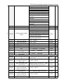
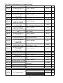
Table of Contents
Preface................................................................................................................................................................ - 1 Table of Contents............................................................................................................................................ - 3 Chapter 1 Safety Precautions...................................................................................................................... - 5 1.1 Safety Considerations...........................................................................................................................- 5 1.2 Precautions.............................................................................................................................................- 7 Chapter 2 Product Information.................................................................................................................... - 9 2.1
2.2
2.3
2.4
2.5
2.6
Nameplate information......................................................................................................................... - 9 Information of FR100 Product Model...............................................................................................- 10 Technical Features of FR100............................................................................................................- 10 Parts Drawing...................................................................................................................................... - 13 External Dimensions of Keypad....................................................................................................... - 13 Configuration, Mounting Dimensions and Weight......................................................................... - 14 -
Chapter 3 Installation and Wiring............................................................................................................. - 15 3.1
3.2
3.3
3.4
3.5
3.6
3.7
3.8
3.9
Installation Environment.....................................................................................................................- 15
Installation Direction, Space and Cooling....................................................................................... - 15
Fixed manner....................................................................................................................................... - 16
Remove & Mount Keypad and Cover..............................................................................................- 17
Dust cover installation and removal(Optional accessories)................................................... - 17
Configuration of Peripheral Devices................................................................................................ - 18
Wiring way............................................................................................................................................ - 19
Terminal Configuration....................................................................................................................... - 21
EMI Solutions.......................................................................................................................................- 26
-
Chapter 4 Operation and display.............................................................................................................. - 28 4.1
4.2
4.3
4.4
4.5
4.6
Introduction of Keypad....................................................................................................................... - 28
Viewing and Modifying Function Codes..........................................................................................- 30
Viewing Status Parameters............................................................................................................... - 31
Motor Auto-tuning................................................................................................................................- 31
Password Setting................................................................................................................................ - 31
Keypad lock..........................................................................................................................................- 31
-
Chapter 5 List of Parameter....................................................................................................................... - 32 5.1 Standard Function Parameters.........................................................................................................- 33 Chapter 6 Specification of Parameters................................................................................................... - 50 Group
Group
Group
Group
Group
Group
Group
Group
Group
Group
Group
Group
Group
F00
F00
F02
F03
F04
F05
F06
F07
F08
F09
F11
F12
F13
System Parameters...............................................................................................................- 50
Frequency command............................................................................................................ - 52
Start/Stop Control Start/Stop Control.................................................................................- 55
Accel/Decel Parameters.......................................................................................................- 58
Digital Input.............................................................................................................................- 60
Digital Output..........................................................................................................................- 66
Analog and Pulse Input........................................................................................................ - 69
Analog and Pulse Output..................................................................................................... - 72
Parameters of Motor 1..........................................................................................................- 72
V/f Control Parameters of Motor 1......................................................................................- 73
Protection Parameters..........................................................................................................- 76
Multi-Reference and Simple PLC Function...................................................................... - 80
Process PID............................................................................................................................- 83
-3-
-
FR100 Series Multifunctional Compact Inverter
Group
Group
Group
Group
Group
F14 Swing Frequency, Fixed Length,Count and Wakeup..................................................... - 85
F15 Communication Parameters................................................................................................ - 88
F16 Keys and Display of Keypad Parameters......................................................................... - 89
U00 Status Monitoring.................................................................................................................. - 89
U01 Fault Record...........................................................................................................................- 90
-
Chapter 7 Maintenance and Troubleshooting.......................................................................................- 91 Chapter 8 Maintenance and Inspection.................................................................................................. - 95 8.1 Inspection............................................................................................................................................. - 95 8.2 Maintenance.........................................................................................................................................- 97 Appendix A: Modbus Communication Protocol...................................................................................- 98 Appendix B: Accessories......................................................................................................................... - 105 B.1 Braking Resistor................................................................................................................................- 105 B.2 Uploading and Downloading Module............................................................................................ - 105 -
-4-
FR100 Series Multifunctional Compact Inverter
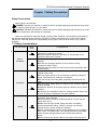
Chapter 1 Safety Precautions
Safety Precautions
Safety signs in this manual:
DANGER: indicates the situation in which the failure to follow operating requirements may result
in fire or serious personal injury or even death.
CAUTION: indicates the situation in which the failure to follow operating requirements may cause
moderate or slight injury and damage to equipment.
Users are requested to read this chapter carefully when installing, commissioning and repairing
this product and perform the operation according to safety precautions as set forth in this chapter
without fail. FRECON will bear no responsibility for any injury and loss as a result of any violation
operation.
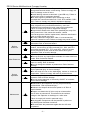
1.1 Safety Considerations
The use phase
Safety
class
Danger
Before
Installation
Caution
Danger
Installation
Caution
Wiring
Danger
Considerations
◆Do not install the product if the package is with water, or
component is missing or broken.
◆Do not install the product if the label on the package is not
identical to that on the inverter.
◆Be careful of carrying or transportation. Risk of devices
damage.
◆Do not use damaged product or the inverters missing
component .Risk of injury.
◆Do not touch the parts of control system with bare hands. Risk
of ESD hazard.
◆Installation base shall be metal or other non-flammable
material. Risk of fire.
◆Do not install inverter in an environment containing explosive
gases, otherwise there is danger of explosion.
◆Do not unscrew the fixing bolts, especially the bolts with red
mark.
◆Do not leave cable strips or screws in the inverter. Risk of
inverter damage.
◆Install the product at the place with less vibration and no direct
sunlight.
◆Consider the installation space for cooling purpose when two
or more inverters are placed in the same cabinet.
◆Wiring must be performed by authorized and qualified
personnel. Risk of danger.
◆Circuit-breaker should be installed between inverter and the
mains. Risk of fire.
◆Make sure the input power supply has been completely
disconnected before wiring. Failure to comply may result in
personnel injury and/or equipment damage.
◆Since overall leakage current of this equipment may be bigger
than 3.5mA, for safety's sake, this equipment and its associated
motor must be well grounded so as to avoid risk of electric
shock.
◆Never connect the power cables to the output terminals (U/T1、
-5-
FR100 Series Multifunctional Compact Inverter
Caution
Danger
Before
Power-on
Caution
Danger
After Power-on
Caution
Danger
During
Operation
Caution
Maintenance
Danger
V/T2、W/T3) of the AC drive. Pay attention to the marks of the
wiring terminals and ensure correct wiring. Failure to comply will
result in damage to the AC drive.
◆Install braking resistors at terminals (+)and PB only. Failure to
comply may result in equipment damage.
◆AC 220V signal is prohibited from connecting to other
terminals than control terminals R1A、R1B、R1C andR2A、R2B、
R2C. Failure to comply may result in equipment damage.
◆Since all adjustable frequency AC drives from FRECON have
been subjected to hi-pot test before delivery, users are
prohibited from implementing such a test on this equipment.
Failure to comply may result in equipment damage.
◆Signal wires should to the best of the possibility be away from
main power lines. If this cannot be ensured, vertical
cross-arrangement shall be implemented, otherwise interference
noise to control signal may occur.
◆If motor cables are longer than 100m, it is recommended
output AC reactor be used. Failure to comply may result in faults.
◆Inverter shall be power-on only after the front cover is
assembled. Risk of electrical hazard.
◆Verify that the input voltage is identical to the rated voltage of
product, correct wiring of input terminals R/L1, S/L2, and T/L3
and output terminals U/T1, V/T2, and W/T3, wiring of inverter
and its peripheral circuits, and all wires should be in good
connection. Risk of inverter damage.
◆Do not open the cover after power.Rick of electrical hazard.
◆Do not touches any input/output terminals of inverter with bare
hands. Rick of electrical hazard.
◆If auto tuning is required, be careful of personal injury when
motor is running. Risk of accident.
◆Do not change the defaults of parameters. Risk of devices
damage.
◆Non-professionals shall not detect signals during operation.
Risk of personal injury or device damage.
◆Do not touch the fan or the discharging resistor to check the
temperature. Failure to comply will result in personal burnt.
◆Prevent any foreign items from being left in the devices during
operation. Risk of device damage.
◆Do not control start/stop of inverter by ON/OFF of contactor.
Risk of device damage.
◆Maintenance and inspection can only be performed by
professionals . Risk of personal injury.
◆Maintain and inspect devices after power is off. Risk of
electric hazard.
◆Repair or maintain the AC drive only ten minutes after
the AC drive is powered off. This allows for the residual
voltage in the capacitor to discharge to a safe value.
Failure to comply will result in personal injury.
◆All pluggable components can be inserted or pulled out
only when power has been turned off.
◆Set and check the parameters again after the AC drive
is replaced.
-6-
FR100 Series Multifunctional Compact Inverter
1.2 Precautions
1.2.1 Motor Insulation Inspection
When the motor is used for the first time or when the motor is reused after being kept, or when
periodical inspection is performed, insulation inspection shall be conducted with motor so as to avoid
damaging the inverter because of the insulation failure of the motor windings. The motor wires must be
disconnected from the inverter during the insulation inspection. It is recommended to use the 500V
mega meter, and the insulating resistance measured shall be 5MΩ at least.
1.2.2 Motor Thermal Protection
If the motor rating does not match that of the inverter, especially when the rated power of the
inverter is higher than that of the motor, adjust motor protection parameters in the inverter or install
thermal relay to protect motor.
1.2.3 Operating with the Frequency Higher than Grid Power Frequency
Output frequency of FR100 is 0.00Hz~600.00Hz. If FR100 is required to operate above 50.00Hz,
please take the endurance of mechanical devices into consideration.
1.2.4 Mechanical Vibrations
Inverter may encounter mechanical resonance point of the load device at certain output
frequencies which can be avoided by setting the skip frequency parameters of the inverter.
1.2.5 Motor Heat and Noise
Since output voltage of inverter is PWM wave and contains a certain amount of harmonics, so
that the temperature, noise and vibration of the motor will be higher than those when the inverter runs
at grid power frequency.
1.2.6 Voltage-sensitive device or capacitor on output side of the AC drive
Do not install the capacitor for improving power factor or lightning protection voltage-sensitive
resistor on the output side of the AC drive because the output of the AC drive is PWM wave.
Otherwise, the AC drive may suffer transient over-current or even be damaged.
1.2.7 Contactor at the I/O terminal of the AC drive
When a contactor is installed between the input side of the AC drive and the power supply, the AC
drive must not be started or stopped by switching the contactor on or off. If the AC drive has to be
operated by the contactor, ensure that the time interval between switching is at least one hour since
frequent charge and discharge will shorten the service life of the capacitor inside the AC drive.
When a contactor is installed between the output side of the AC drive and the motor, do not turn off the
contactor when the AC drive is active. Otherwise, modules inside the AC drive may be damaged.
1.2.8 Applied with the Rated Voltage
Apply FR100 with the rated voltage. Failure to comply will damage inverter. If required, take a
transformer to boost or step-down voltage.
1.2.9 Do Not Apply a 3-Phase Input Inverter to 2-Phase Input Applications
Do not apply a 3-phase input FR inverter to 2-phase input applications. Otherwise, it will result in
faults or damage inverter.
1.2.10 Lightning Protection
FR100 has integrated lightning over-current protection device which has certain self-protection
capacity against the lightning. Additional protection devices have to be installed between inverter
and power supply in the area where lightning occurs frequently.
1.2.11 Altitude De-rating
In places where the altitude is above 1000 m and the cooling effect reduces due to thin air, it is
necessary to de-rate the AC drive. Contact FRECON for technical support.
1.2.12 Some Special Usages
If wiring that is not described in this manual such as common DC bus is applied, contact the agent
or FRECON for technical support.
1.2.13 Cautions for Inverter Disposal
The electrolytic capacitors on the main circuit and PCBA may explode when they are burnt.
Emission of toxic gas may be generated when the plastic parts are burnt. Please dispose inverter as
industrial wastes.
1.2.14 Adaptable Motor
The standard adaptable motor is adaptable four-pole squirrel-cage asynchronous induction motor
or PMSM. For other types of motor, select a proper AC drive according to the rated motor current.
The cooling fan and rotor shaft of non-variable-frequency motor are coaxial, which results in
reduced cooling effect when the rotational speed declines. If variable speed is required, add a more
powerful fan or replace it with variable-frequency motor in applications where the motor overheats
easily.
-7-
FR100 Series Multifunctional Compact Inverter
The standard parameters of the adaptable motor have been configured inside the AC drive. It is
still necessary to perform motor auto-tuning or modify the default values based on actual conditions.
Otherwise, the running result and protection performance will be affected.
The AC drive may alarm or even be damaged when short-circuit exists on cables or inside the
motor. Therefore, perform insulation short-circuit test when the motor and cables are newly installed or
during routine maintenance. During the test, make sure that the AC drive is disconnected from the
tested parts.
-8-
FR100 Series Multifunctional Compact Inverter
Chapter 2 Product Information
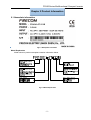
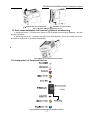
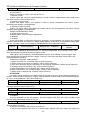
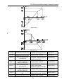
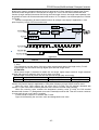
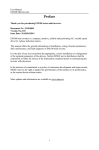
2.1 Nameplate information
Fig.2-1 Nameplate information
Model Explanation
Model show on product nameplate contains information below
Fig.2-2 Model Explanation
-9-
FR100 Series Multifunctional Compact Inverter
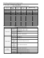
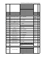
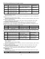
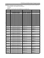
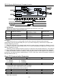
2.2 Information of FR100 Product Model
Table 2-1 FR100 Product model and technical data
Power
Rated Input
Rated output
Model No.
capacity
current
current
KVA
A
A
Single-Phase:220V,50/60Hz
Range:-15%~+30%
FR100-2S-0.2B
0.5
FR100-2S-0.4B
1.0
FR100-2S-0.7B
1.5
FR100-2S-1.5B
3.0
FR100-2S-2.2B
4.0
3-Phase:220V,50/60Hz
FR100-2T-0.2B
0.5
FR100-2T-0.4B
1.0
FR100-2T-0.7B
3.0
FR100-2T-1.5B
4.0
FR100-2T-2.2B
6.0
3-Phase:380V,50/60Hz
FR100-4T-0.7B
1.5
FR100-4T-1.5B
3.0
FR100-4T-2.2B
4.0
FR100-4T-4.0B
6.0
4.9
1.6
6.5
2.5
9.3
4.2
15.7
7.5
24
9.5
Range:-15%~+30%
1.9
1.6
2.7
2.5
4.9
4.2
9.0
7.5
11
9.5
Range:-15%~+30%
3.4
2.5
5.0
4.2
5.8
5.5
11
9.5
Applicable motor
kW
HP
0.18、0.2、0.25
0.37、0.4
0.75
1.5
2.2
0.25
0.5
1.0
2
3
0.18、0.2、0.25
0.37、0.4
0.75
1.5
2.2
0.25
0.5
1
2
3
0.75
1.5
2.2
3.7、4
1
2
3
5
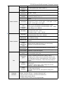
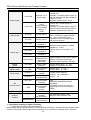
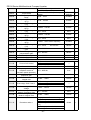
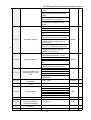
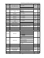
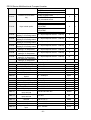
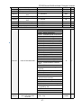
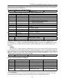
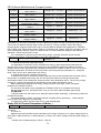
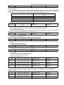
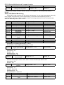
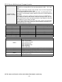
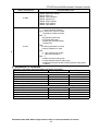
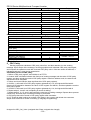
2.3 Technical Features of FR100
Table 2-2 Technical features of FR100
Project
Rated input
voltage (V)
Power input
Power output
Rated input
current (A)
Rated input
frequency
(Hz)
Applicable
motor(kW)
Rated output
current(A)
The
maximum
output
voltage(V)
The
maximum
output
frequency
(Hz)
V/f patterns
Control
characteristics
Speed range
Speed
accuracy
Speed
Specifications
Single-Phase 220V(-15%~+30%)
3-phase 220 V (-15%~+30%)
3-phase 380 V (-15%~+30%)
See table 2-1
50Hz/60Hz,tolerance±5%
See table 2-1
See table 2-1
0~rated input voltage, error<±3%
0.00~600.00 Hz,unit0.01Hz
V/f control
Sensor-less vector control 1
1:50 (V/f control)
1:100 (sensor-less vector control 1)
±0.5% (V/f control)
±0.2% (sensor-less vector control 1 )
±0.3% (sensor-less vector control 1 )
- 10 -
FR100 Series Multifunctional Compact Inverter
fluctuation
Torque
response
Starting
torque
Carrier
frequency
Overload
capability
Torque boost
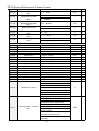
Basic functions
V/F Curve
Acceleration
and
deceleration
Curve
< 10ms (sensor-less vector control 1 )
0.5Hz: 180% (V/f control, sensor-less vector control 1)
0.7kHz~16kHz
G Model:150% Rated Current 60s,180% Rated Current
10s,200% Rated Current 1s.
Automatic torque boost;Manual torque boost 0.1%~
30.0%
Three ways:Three ways: straight; multi-point type; N
Th-type V / F curve(1.2 Th -type、1.4 Th -type、1.6 Th
-type、1.8 Th -type、2 Th -type)
Line or curve acceleration and deceleration mode.
Four kinds of acceleration and deceleration time,Ramp
Time Range :0.0~6000.0s
DC brake start frequency: 0.00~600.00Hz
DC brake time:0.0s~10.0s
DC brake current:0.0%~150.0%
Jog frequency range:0.00Hz~50.00Hz.
Jog brake
Jog deceleration time: 0.0s~6000.0s.
Simple PLC、 Through the built-in PLC or control terminal to achieve up
to 16 speed running
Multi-speed
Facilitate the realization of process control loop control
Built-in PID
system
Automatic
voltage
When the grid voltage changes, can automatically
adjustment
maintain a constant output voltage
(AVR)
Fast current
Minimize over current fault protection inverter running
limit function
Over voltage
System automatically limits of current and voltage during
Over current
operation to prevent frequent
Command
Given the control panel, control terminal, serial
source
communication port given.
Sevkeinradlswoafysfrtoeqsuweintcchy sources: digital
setting, keyboard potentiometer setting, analog
Frequency
Voltage, given analog current reference pulse is given,
given
the serial port is given, multi-speed given, PLC is given,
the process PI D reference. There are several ways to
switch
5Switch input terminals, one way to make high-speed
Input
pulse input.
terminal
2-channel analog inputs,1-way voltage and current
options,1- way to support input
1-way switch output terminal
output
1 relay output terminals
terminal
1 analog output terminal, and optional voltage and
current.
Parameter copy 、 parameter backup 、 flexible parameter displayed &
hidden. Common DC bus(Contains below 30 KW).
Various master & auxiliary command and switchover.
Reliable speed search started.
A variety of Accel / Decel curves programmable.
DC brake
Basic functions
Run
Featured
functions
- 11 -
FR100 Series Multifunctional Compact Inverter
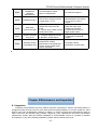
Protection
function
Display and
keyboard
Environment
Others
Timing control、 fixed length control、count function.
Three faults recorded.
Over excitation brake、overvoltage stall protection programmable、under
voltage stall protection programmable、restart upon power loss.
Four kinds of Accel/Decel time.
Motor thermal protection.
Flexible fan control.
Process PID control、simple PLC、16-step speed control programmable.
Wobble frequency control.
Multi-functional key programmable、field-weakening control.
High-precision torque control 、 V/f separated control 、 torque control at
sensor-less vector control.
Provide fault protection dozen:Overcurrent、Overvoltage、Undervoltage、
Overtemperature、Overload Etc Protection.
LED Display
Display Parameters
Key lock and
Realize some or all of the keys locked, scope definition
function
section keys to prevent misuse
selection
Run and stop
In the run or stop can be set to monitor U00 group four
monitoring
objects were.
information
Indoors, no direct sunlight, free from dust, corrosive
Place of
gases,
operation
flammable gases, oil mist, water vapor, water drop and
salt, etc.
0~2000m
Altitude
De-rate 1% for every 100m when the altitude is above
1000 meters
Ambient
-10℃~40℃
temperature
Relative
5~95%, no condensation
humidity
Vibration
Less than 5.9m/s2 (0.6g)
Storage
-20℃~+70℃
temperature
Efficiency
Rated power≥93%
Installation
Wall-mounted or DIN-rail mounting
IP grade
IP20
Cooling
Fan cooled
method
2.4 Parts Drawing
Fig 2-3
Outline example
- 12 -
FR100 Series Multifunctional Compact Inverter
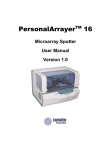
2.5 External Dimensions of Keypad
Fig 2-4 Keyboard size diagram
External keyboard installation:
If the keyboard need to be installed externally,Punch one hole as shown in fig 2-5; Install the
keyboard in the panel as shown in fig. Disassemble keypad by pressing keypad buckle with a slotted
screwdriver on the back of the panel (Refer to A in the Figure).
Fig 2-5 External keyboard installation whole size diagram
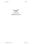
2.6 Configuration, Mounting Dimensions and Weight
Fig 2-6 Product size chart
- 13 -
FR100 Series Multifunctional Compact Inverter
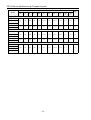
Table 2-3 Configuration, mounting dimensions and weight
External and installation dimensions(mm)
Model
W
H
D
W1
W2
H1
H2
H3
H4
Install
Hole
d1
Install
Hole
N.W
(Kg)
d2
Single-Phase :220V,50/60Hz
FR100-2S-0.2B
FR100-2S-0.4B
95
162
120
85
11
151.5
152
110.8
130
4.5
4.5
1.1
110
173
135
100
11
163
163
121.8
140.5
4.5
5
1.5
FR100-2S-0.7B
FR100-2S-1.5B
FR100-2S-2.2B
3-Phase :220V,50/60Hz
FR100-2T-0.2B
FR100-2T-0.4B
95
162
120
85
11
151.5
152
110.8
130
4.5
4.5
1.1
110
173
135
100
11
163
163
121.8
140.5
4.5
5
1.5
135
100
11
163
163
121.8
140.5
4.5
5
1.5
FR100-2T-0.7B
FR100-2T-1.5B
FR100-2T-2.2B
3-Phase :380V,50/60Hz
FR100-4T-0.7B
FR100-4T-1.5B
FR100-4T-2.2B
110
173
FR100-4T-4.0B
- 14 -
FR100 Series Multifunctional Compact Inverter
Chapter 3 Installation and Wiring
3.1 Installation Environment
1) Ambient temperature in the range of -10℃~50℃.
2) Drive should be installed on surface of flame retardant object, with adequate surrounding space for
heat dissipation.
3) Installation should be performed where vibration is less than 5.9m/s2 (0.6g).
4) Avoid from moisture and direct sunlight.
5) Protect the cooling fan by avoiding oil, dust and metal particles;
6) Do not expose to an atmosphere with flammable gases, corrosive gases, explosive gases or other
harmful gases.
7) Prevent drilling residues, wire ends and screws falling into drive.
8) Ventilation part of the drive should be installed outside from harsh environment (e.g. Textile facilities
with fiber particles and chemical facilities filled with corrosive gases or Loaded dust cover).
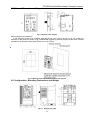
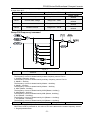
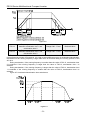
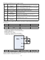
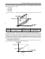
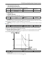
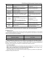
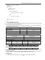
3.2 Installation Direction, Space and Cooling
A fan is integrated in FR100 for forced air cooling. FR100 has to be installed vertically for the purpose
of good cooling circulation. Sufficient spaces have to be left between FR100 and its peripheral objects.
Multi- FR100 can be installed in parallel horizontally e and vertically. See followings for specific space
requirement, heat dissipating capacity and mass airflow.
(a)Inverter transversely-mounted diagram
(b)Inverter vertical-mounted diagram
Fig 3-1 Installation methods
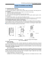
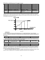
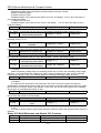
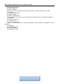
3.3 Fixed manner
a.Four-hole fixation
Size of four holes (Hole a) refer to product dimensions and installation dimensions,as the figure
below 3-2(a), drilling four holes in the mounting surface and put inverter against the mounting surface
with four holes level,and then insert screws into four holes and fixed (any two of the four holes on the
cross installed is available, all four holes screwed for enhanced installation, screw size is M4*L(Length
L longer than 12mm,torque 1N.m±10%).
b.Three-hole fixation
Size of three holes (Hole b) refer to product dimensions and installation dimensions,as the figure
below 3-2(b), drilling three holes in the mounting surface and insert three screws into mounting surface,
no tight, reserving an appropriate distance between screw washer and mounting surface (7.5~9mm),
and then hang the inverter from top to bottom with 3 screws(M4*L, length L longer than 16mm, torque
1N.m±10%) and tight two screws at the lower end.
c.DIN Slot Rail fixation(Using 35mm DIN Rail)
Installation size of DIN rail mounting refer to product dimension and installation dimension. Install
- 15 -
FR100 Series Multifunctional Compact Inverter
or remove the inverter as figure 3-2(c), please press the buckle release key of DIN rail when installing
or removing the inverter.
(a)Four-hole fixation
(b)Three-hole fixation
Fig3-2 Fixation
(c)DIN Slot Rail fixation
Do not take the sunken screws as shown in the
picture. Otherwise, inverter may be damaged
Take screws combined with springs and plain gaskets to
Install inverter.
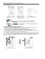
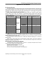
3.4 Remove & Mount Keypad and Cover
a. Remove keypad: Disassemble keypad. See following Figure: 3-3(a)Push the buckle on
the keypad in Direction 1 first, and then lift up the keypad in Direction 2.
b. Mount keypad: Assemble keypad. See following Figure:3-3(b) Place keypad in the slot in
Direction 1, and then press the keypad in Direction 2 until it clicks into right place.
c. Disassembly of Terminal Cover:loosen the captive cover screws as shown in Fig.3-3(c),then
remove terminal cover in the direction as shown in the Figure below.
d. Assemble of Terminal Cover: See following Figure: 3-3(d)Place the upper buckle of the terminal
cover in the slot of upper housing in Direction 1, and then press the two lower buckle of terminal cover
I Direction 2 until it clicks into right place of upper housing. , then Tighten the screws as shown in
Fig.3-3
1
Fig.3-7(a) Remove keypad
Fig.3-7(b) Mount keypad
- 16 -
FR100 Series Multifunctional Compact Inverter
(c)Disassembly of Terminal Cover
(d)Assemble of Terminal Cover
Fig.3-3 Remove & Mount Keypad and Cover
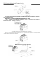
3.5 Dust cover installation and removal(Optional accessories)
a. Install dust cover:The dust cover shown in Fig3-4 parallel to the housing assembly(No cock
around is installed).
b. Removing dust cover:cording to the dust cover arrow direction, at one end of the dust cover
and hard to lift the dust cover under the desirable.
Fig.3-4Dust cover installation and removal
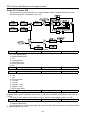
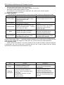
3.6 Configuration of Peripheral Devices
Fig.3-5 Standard configuration of peripheral device
- 17 -
FR100 Series Multifunctional Compact Inverter
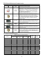
Table 3-1 Instructions of peripheral devices
Picture
Device
Instructions
Cable
Transmitting electrical signals.
Circuit
breaker
Input chokes
Input filter
Purpose: disconnect power supply and protect the
equipments in case of abnormal overcorrect occurs
Type selection: breaking current of circuit breaker is
defined to be 1.5~2 times the rated current of the
drive Breaking time characteristic of circuit breaker
should be selected based on
overload protection time characteristic of the drive
Improve power factor Reduce the impact of
imbalanced three-phase input AC power supply on
the system Suppress higher harmonics and reduce
the conducted and radiated interference to peripheral
devices Restrict the impact of impulse current on
rectifier bridges
Reduce conducted interference from power supply to
the drive, improve the immunity of the drive from noise
Reduce conducted and radiated interference of the
drive to peripheral device
Braking
resistor
Purpose: consume motor feedback energy to attain
quick brake
Output filter
Output filter and radiated interference of the drive to
peripheral devices
Output AC
reactor
Avoid the motor insulation damage result from
harmonic voltage Reduce frequent protection from the
drive caused by leakage current In case the cable
connecting drive and motor is over 100 meters, output
AC reactor recommended
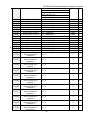
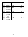
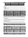
3.6.1 Selection of Peripheral Devices
Table 3-2 Selection of peripheral devices
Model
L1、L2、L3
Single-Phase:220V
FR100-2S-0.2B
FR100-2S-0.4B
FR100-2S-0.7B
FR100-2S-1.5B
FR100-2S-2.2B
3-Phase:220V
FR100-2T-0.2B
FR100-2T-0.4B
FR100-2T-0.7B
FR100-2T-1.5B
FR100-2T-2.2B
3-Phase:380V
FR100-4T-0.7B
FR100-4T-1.5B
FR100-4T-2.2B
FR100-4T-4.0B
Cable(mm2)
(+)
、(-)
、
U、V、W
PB
PE
Circuit
breaker
(A)
contactor
(A)
1.5
2.5
2.5
4
4
1.5
1.5
1.5
2.5
2.5
1.5
1.5
1.5
2.5
2.5
1.5
1.5
1.5
2.5
2.5
10
16
16
20
32
10
10
10
16
16
1.5
2.5
2.5
2.5
4
1.5
1.5
1.5
2.5
2.5
1.5
1.5
1.5
2.5
2.5
1.5
1.5
1.5
2.5
2.5
6
10
16
16
20
6
10
10
10
16
2.5
2.5
2.5
2.5
2.5
2.5
2.5
2.5
2.5
2.5
2.5
2.5
2.5
2.5
2.5
2.5
6
10
16
16
10
10
10
10
- 18 -
FR100 Series Multifunctional Compact Inverter
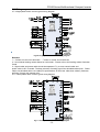
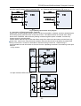
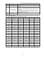
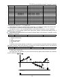
3.7 Wiring way
3.7.1Single-phase 220V inverter typical wiring diagram
Fig.3-6 Single-phase 220V Inverter wiring diagram
Remarks:
○
1)◎refers to main circuit terminals., refers to control circuit terminals.
2)User selects braking resistor based on real needs,Please refer to the braking resistor Selection
Guide.
3)Signal cable and power cable should be separated. Try to cross control cable and
power cable in 90° if needed. The best selection of analog signal lines shielded twisted pair,Power
cables use shielded three-core cable(The specifications of the motor cable than ordinary freshman
profile)or Comply with manual drive.
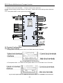
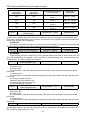
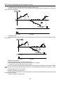
3.7.2 Three-phase 220V inverter typical wiring diagram
Fig.3-7 Three-phase220V Inverter wiring diagram
- 19 -
FR100 Series Multifunctional Compact Inverter
Remarks:
○
1)◎refers to main circuit terminals., refers to control circuit terminals.
2)User selects braking resistor based on real needs,Please refer to the braking resistor Selection
Guide.
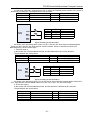
3.7.3 Three-phase 380V inverter typical wiring diagram
Fig.3-8Three-phase 380V Inverter wiring diagram
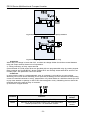
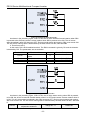
3.8 Terminal Configuration
3.8.1 Main Circuit Terminals
a: Single-phase and three-phase 220V 0.2~0.75KW Main Circuit Terminals
Fig.3-9 0.2~0.75kW main circuit terminals
b: Three-phase 220V 1.5~2.2KW and three-phase 380V 0.75~4.0 KW Main Circuit Terminals
Fig.3-10 Three-phase 220V 1.5~2.2KW and three-phase 380V 0.75~4.0 KW Main Circuit Terminals
- 20 -
FR100 Series Multifunctional Compact Inverter
Table 3-5 main circuit terminal functions
Terminal marks
L1、L2、L3
U、V、W
(+)、(-)
PB
Designation and function of terminals.
AC power input terminal, connects to three-phase 380V or
220V AC power (For the machine with single-phase 220V: L1、
L2 connect to single-phase 220V AC power, L3 terminal left
unconnected)
AC output terminals of inverter for connecting to 3-phase
induction motor.
Positive and negative terminals of internal DC bus.
Positive and negative terminals of internal DC bus. Connecting
terminals of braking resistor. One end connected to + and the
other to PB.
Grounding terminal.
Remarks: No phase sequence requirements on wiring of the input side of inverter. Wiring
Precautions:
1)Power input terminals L1、L2 、L3
◆ The cable connection on the input side of the AC drive has no phase sequence requirement.
2)DC bus (+)、(-)
◆ Terminals (+) and (-) of DC bus have residual voltage after the AC drive is switched off. After
indicator CHARGE goes off, wait at least 10 minutes before touching the equipment Otherwise, you
may get electric shock.
◆ Do not connect the braking resistor directly to the DC bus. Otherwise, it may damage the AC drive
and even cause fire.
3)Braking resistor connection terminals (+)、PB
◆ The cable length of the braking resistor shall be less than 5 m. Otherwise, it may damage the AC
drive.
4)AC drive output terminals U、V、W
◆ The capacitor or surge absorber cannot be connected to the output side of the AC drive. Otherwise,
it may cause frequent AC drive fault or even damage the AC drive.
If the motor cable is too long, electrical resonance will be generated due to the impact of distributed
capacitance. This will damage the motor insulation or generate higher leakage current, causing the AC
drive to trip in overcurrent protection. If the motor cable is greater than 100 m long, an AC output
reactor must be installed close to the AC drive.
5)Terminal PE
◆ This terminal must be reliably connected to the main earthing conductor. Otherwise, it may cause
electric shock, mal-function or even damage to the AC drive.
◆ Do not connect the earthing terminal to the neutral conductor of the power supply.
3.8.2 Control circuit terminals
Fig.3-11 Control circuit terminals
- 21 -
FR100 Series Multifunctional Compact Inverter
Table 3-4 FR100 Description of control circuit terminals
Type
Terminal
Name
+10V-GND
External +10 V
power supply
+24V-COM
External +24V
power
supply Applying
to Overvoltage
Category II
circuit
AI1-GND
Analog input 1
AI2-GND
Analog input 2
Power supply
Analog input
DI1- GND
DI2- GND
DI3- GND
Switch input
DI4- GND
DI7/HI-COM
Analog
output
AO1-GND
Switch output
Y1-GND
Relay output
R1A-R1C
R1B-R1C
485+-485-
485
Communication
GND
Shield
PE
Auxiliary
Interface
UP/DOWNLOAD
Switch input
terminals 1
Switch input
terminals 2
Switch input
terminals 3
Switch input
terminals 4
Switch input
terminals 7 OR
High-speed
pulse input
Analog output
terminal 1
Open collector
output 1
Normally open
terminal
Normally
closed terminal
485
Communication
Terminals
485
Communication
shielded
ground
Shield Ground
External
operation
panel interface
Parameter
copy interface
Function Description
Provide +10 V power supply to
external unit.
Generally, it provides power supply to
external potentiometer with resistance
range of 1–5 kΩ.
Maximum output current: 10 mA
Provide +24 V power supply to
external unit.
Generally, it provides power supply to
DI/Do terminals and external sensors.
Maximum output current: 200 mA
Input voltage range:DC 0~10V/0~
20mA,decided by toggle switches
AI1、AI2 on the control board
Impedance: 250 kΩ (voltage input),
250 Ω (current input)
Maximum input frequency:200Hz
Impedance:2.4kΩ
Voltage range for level input:9V~
30V
Besides features of DI1–DI4, it can be
used for high-speed pulse input.
Maximum input frequency: 100 kHz
Output voltage range:0~10V
Impedance requirements≥10kΩ
Voltage range:0~24V
Current range:0~50mA
Contact driving capacity:
AC250V,3A,COSØ=0.4.
DC 30V,1A
Rate:
4800/9600/19200/38400/57600/
115200bps
Termination resistor is set by the
toggle switch on the control panel
RS485
Ground terminal for shield
Use standard network cable
Maximum cable distance: 50m
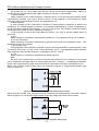
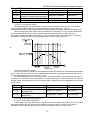
1、Description of Wiring of Signal Terminals:
1)Description Use the analog input terminal
Weak analog voltage signals are easy to suffer external interference, and therefore the shielded cable
must be used and the cable length must be less than 20 m, as shown in following figure. When the
- 22 -
FR100 Series Multifunctional Compact Inverter
analog input signal to an external power supply,AI1 Terminal wiring as shown in Fig 3-12(a).When
the input analog voltage signal is potentiometer,AI1 Terminal wiring as shown in Fig 3-12(b).
(a)
Fig.3-12 Analog input terminal wiring diagram
(b)
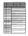
2)Instructions of Digital Input/output Terminals
Digital input & output signals cables should be as short as possible, shielded, and their shielded layers
should be properly grounded close to the side of drive. The cables should not exceed 20m. When
active drive is selected, take necessary filtering measures against power crosstalk, for which dry
contact control is recommended.
Control cables shall be kept no less than 20cm away from main circuit and strong current lines (e.g.
power lines, motor lines, relay lines and contactor lines) and should not be arranged in parallel with
strong current lines. In case it is inevitable to intersect strong current line, vertical wiring is
recommended to avoid drive faults as a result of noise. Operating instructions for switching value input
terminal
A: Dry contact
Fig.3-13 Dry contact
B: Open collector NPN connection
Fig.3-14 Open collector NPN connection
- 23 -
FR100 Series Multifunctional Compact Inverter
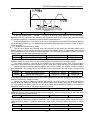
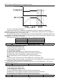
3)Instructions of digital output terminal
Fig.3-15 wiring when Y2 and HO output with pull-up resistors
Fig.3-20 Wiring diagram when Y2 and HO drive relay
ATTENTION:
When relay coil voltage is lower than 24V, a resistor as voltage divider should be mounted between
relay and output terminal, based on coil impedance.
4)Wiring instruction of relay output terminal
Control boards of FR100 series drives are provided with one programmable relay dry contact outputs.
Relay contacts are R1A/R1B/R1C, whose R1Band R1C are normally closed while R1A and R1C are
normally open. See parameter F05.02 for details.
ATTENTION:
In case inductive load (e.g. electromagnetic relay or contactor) is to be driven, a surge voltage
absorbing circuit such as RC absorbing circuit (note that its leakage current shall be less than holding
current of controlled contactor or relay), piezoresistor or fly-wheel diode etc. shall be mounted (be sure
to pay close attention to polarity in case of DC electromagnetic circuit). Absorbing devices should be
mounted close to the ends of relay or contactor.
5) Instruction of Signal Switch
Terminal
AI2
RS485
Function
I: current input (0~20mA); V: voltage input (0~10V)
Selection of 485 termination resistor; ON :120Ω termination
resistor provided; OFF: no termination resistor
- 24 -
Factory
default
0~10V
No
termination
resistor
FR100 Series Multifunctional Compact Inverter
3.9 EMI Solutions
Due to its working principle, the drive will inevitably produce certain noise that may influence and
disturb other equipment. Moreover, since the internal weak electric signal of drive is also susceptible
to the interference of drive itself and other equipment, EMI problems shall be inevitable. In order to
reduce or avoid the interference of drive to external environment and protect drive against interference
from external environment, this section makes a brief description of noise abatement, ground handling,
leakage current suppression and the application of power line filters.
3.9.1 Noise Abatement
When peripheral equipment and drive share the power supply of one system, noise from drive
may be transmitted to other equipment in this system via power lines and result in misoperation
and&or faults. In such a case, the following measures could be taken:
1) Mount input noise filter at input terminal of the drive;
2) Mount power supply filter at power input terminal of affected equipment;
3) Use isolation transformer to isolate the noise transmission path between other equipment and the
drive.
As the wiring of peripheral equipment and drive constitutes a circuit, the unavoidable earthing
leakage current of inverter will cause equipment misoperation and/or faults.
Disconnect the grounding connection of equipment may avoid this misoperation and/or faults
Sensitive equipment and signal lines shall be mounted as far away from drive as possible.
Signal lines should be provided with shielded layer and reliably grounded. Alternatively, signal
cable could be put into metallic conduits between which the distance shall be no less than 20cm, and
shall be kept as far away from drive and its peripheral devices, cables as possible. Never make signal
lines in parallel with power lines or bundle them up.
Signal lines must orthogonally cross power lines if this cross inevitable.
Motor cables shall be placed in thick protective screen like more than 2mm-thick pipelines or
buried cement groove, also, power lines can be put into metallic conduit and grounded well with
shielded cables.
Use 4-core motor cables of which one is grounded at close side of the drive and the other side is
connected to motor enclosure.
Input and output terminals of drive are respectively equipped with radio noise filter and linear
noise filter. For example, ferrite common mode choke can restrain radiation noise of power lines.
3.9.2 Grounding
Recommended ground electrode is shown in the figure below:
变频器
Drive
Drive
变频器
Drive
变频器
Drive
变频器
Drive
变频器
Drive
变频器
Fig.3-17v
Use to the fullest extent the maximum standard size of grounding cables to reduce the impedance of
grounding system;
Grounding wires should be as short as possible;
Grounding point shall be as close to the drive as possible;
One wire of 4-core motor cables shall be grounded at the drive side and connected to grounding
terminal of motor at the other side. Better effect will be achieved if motor and drive are provided with
dedicated ground electrodes;
When grounding terminals of various parts of system are linked together, leakages current turns into
a noise source that may influence other equipment in the system, thus, grounding terminals of the
drive and other vulnerable equipment should be separated.
Grounding cable shall be kept away from inlet & output of noise-sensitive equipment.
3.9.3 Leakage Current Suppression
Leakage current passes through the line-to-line and ground distributed capacitors at input & output
sides of drive, and its size is associated with the capacitance of distributed capacitor and the carrier
frequency. Leakage current is classified into ground leakage current and line-to-line leakage current.
Ground leakage current not only circulates inside drive system, but may also influence other
- 25 -
FR100 Series Multifunctional Compact Inverter
equipment via ground loop. Such a leakage current may result in malfunction of RCD and other
equipment. The higher the carrier frequency of drive is, the bigger the ground leakage current would
be. The longer the motor cables and the bigger the parasitic capacitances are, the bigger the ground
leakage current would be. Therefore, the most immediate and effective method for suppression of
ground leakage current is to reduce carrier frequency and minimize the length of motor cables.
The higher harmonics of line-to-line leakage current that pass through between cables at output
side of drive will Accel the aging of cables and may bring about malfunction of other equipment. The
higher the carrier frequency of drive is, the bigger the line-to-line leakage current would be. The longer
the motor cables and the bigger the parasitic capacitances are, the bigger the line-to-line leakage
current would be. Therefore, the most immediate and effective method for suppression of ground
leakage current is to reduce carrier frequency and minimize the length of motor cable. Line-to-line
leakage current can also be effectively suppressed by mounting additional output reactors.
3.9.4 Use of Power Supply Filter
Since AC drives may generate strong interference and are also sensitive to outside interference,
power supply filters are recommended. Pay close attention to the following instructions during the use:
Enclosure of the filter needs to be reliably grounded;
Input lines of the filter shall be kept as far away from output lines as possible so as to avoid mutual
coupling;
Filter shall be as close to the drive side as possible;
Filter and drive must be connected to the same common ground.
- 26 -
FR100 Series Multifunctional Compact Inverter
Chapter 4 Operation and display
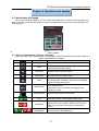
4.1 Introduction of Keypad
As a human-machine interface, you can modify the parameters, monitor the working status and
start or stop the inverter by operating the keypad. Its appearance and function area as shown in the
following figure:
Fig.4-1 Keypad
4.1.1 Key and potentiometer Functions on keypad
There are 8 keys and a potentiometer on the keypad, whose functions are as shown in Table 4-1.
Table 4-1 Key functions on keypad
Symbol
Name
Escape
Enter
Enter or exit Level I menu
Enter the menu interfaces level by level, and
confirm the parameter setting
Increment
Increase data or function code
Decrement
Decrease data or function code
Shift
Multifunction
potentiometer
Run
Stop/Reset
+
Function
Key
combinations
Select the displayed parameters in turn in the stop
or running state, and select the digit to be modified
when modifying parameters
Perform function switchover (such as jog run and
quick switchover of
command source or direction) according to the
setting of F16.00
With the same function as AI1/AI2
Start the inverter in the keypad control mode
Stop the inverter when it is in the running state and
perform the reset operation when it is in the fault
state. The functions of this key are restricted in
F16.01.
The inverter will free stop when the run and stop
key are pressed simultaneously
- 27 -
FR100 Series Multifunctional Compact Inverter
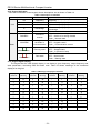
4.1.2 Keypad Indicators
There are 8 Indicators on the keypad, whose descriptions are as shown in Table 4-2.
Table 4-2 Description of indicators
Indicator
Unit
Name
Hz
Frequency
V
A
Voltage
Current
%
Percentage
All off
Other unit
FWD/REV
Forward or
reverse
LOC/REM
Keypad,
terminals or
communication
State
Running state
(Green border)
Fault state
(Red border)
Meaning
ON: currently displayed parameter is
frequency
ON:currently displayed parameter is voltage
ON:currently displayed parameter is current
ON:currently displayed parameter is
percentage
Other unit or no unit
ON:the drive is running reverse
OFF:the drive is running forward
Flash:dormant state
ON:Terminal control
OFF:Keypad control
Flash:Communication control
ON:Running state
OFF:Stopped state
Flash:In process of stop
ON:Fault state
OFF:Normal state
Flash:Warning state
4.1.3 Keypad digital display
The keypad has five LED (digital) display, it can display a given frequency, output frequency and
other parameters, monitoring data and alarm code. Table 4-3 shows meanings of the characters
displayed on Keypad .
Table 4-3 Meanings of displayed characters
Displayed
character
Character
Meaning
Displayed
character
Character
Meaning
Displayed
character
Character
Meaning
Displayed
character
Character
Meaning
0
1
2
3
4
5
6
7
8
9
0
1
2
3
4
5
6
7
8
9
A
b
C
c
d
E
F
G
H
h
A
b
C
c
d
E
F
G
H
h
I
J
L
N
n
o
p
q
r
S
I
J
L
N
n
o
p
q
r
S
T
t
U
u
y
8.
.
T
t
U
u
y
8.
.
- 28 -
FR100 Series Multifunctional Compact Inverter
4.1.4 Message status
A message appears when the state of completion of certain operations. Prompt message
characters and their meanings are specified in Table 4-4.
Table 4-4 Prompt characters
Prompt symbol
Meaning
Prompt symbol
Err.00~Err.99
Fault type
TUNE
Arn.00~Arn.99
Alarm type
-END-
Meaning
Motor parameter
identification in
process
Write parameter
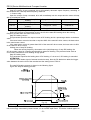
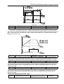
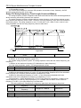
4.2 Viewing and Modifying Function Codes
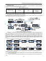
The keypad of the FR100 adopts three-level menu.
The three-level menu consists of function code group (Level I), function code (Level II), and function
code setting value (level III), as shown in the figure 4-2.
Fig.4-2 Operation procedure on the keypad
Explanation:In the level III menu, you can press the ESC key or ENT key to return to the level II
menu. The difference is: If you do not have to modify the function code setting, press ENT will be
automatically transferred to the next function code; If the function code settings are modified, it will
display munu "-END-" 1 second when press ENT key, and redisplay the current function code settings,
and it will be automatically transferred to the next function code when press the ENT key again. Press
the ESC key to abandon the current parameter changes directly returns the current function code in
level II.
Here is an example of changing the value of F1-02 to 15.00 Hz.
Fig.4-3 Example of changing the parameter value
In Level III menu, if the parameter has no blinking digit, it means that the parameter cannot be
modified. This may be because:
(1)Such a function code is only readable, such as, AC drive model, actually detected parameter
and running record parameter.
(2)Such a function code cannot be modified in the running state and can only be changed at
stop.
- 29 -
FR100 Series Multifunctional Compact Inverter
4.3 Viewing Status Parameters
There are stop state parameters and running state parameters.
It has 4 status parameters in the stop or running state .You can press “>>” on the keypad to display
status parameters. Which parameters are displayed is determined by the values of F16.03~F16.06
(Running state parameters 1~4)
、F16.07~F16.10(stop state parameters1~4)
,it can select the
U00 group.
4.4 Motor Auto-tuning
Tuning is valid only when the keyboard command mode. Set tuning mode (stationary or rotating),
press the ENT key to confirm, the keyboard will display TUNE, then press the RUN key, the inverter
will drive motor acceleration and deceleration, positive inversion operation,and the run indicator lights.
Tuning duration of about two minutes, when the display TUNE message disappears, returning to
normal parameter display status, which means that the tuning is completed.
4.5 Password Setting
The inverter provides password protection function, it is set a user's password when F00.00 set to
nonzero.If five minutes without operating the keypad, the password protection is effective, and the
keypad will show “-----”, then the user must enter the correct password to enter the regular menu,
otherwise inaccessible.
There are three ways a user password into force:
Method 1: Set F00.00 parameter to nonzero, then press the ESC + ENT key.
Method 2: Set F00.00 parameter to nonzero, then do not use the keypad within five minutes.
Method 3: Set F00.00 parameter to nonzero, then completely power down and then power.
If you want to cancel the password protection functions, only through a password to enter, and set
F00.00 to 0.
4.6 Keypad lock
4.6.1 Keypad lock
The following three methods to any one immediately lock all or part of the keypad buttons; see the
definition of the function code F16.02.
Method 1:Set F16.02parameter to nonzero, then press the ESC + ENT key.
Method 2:Set F16.02 parameter to nonzero, and then do not use the keypad within five minutes.
Method 3:Set F16.02 parameter to nonzero, then completely power down and then power.
4.6.2 Keypad unlock
Press the ESC + >> keys to unlock.Unlocking operation does not change the value of F16.02,
That means when Meet the keypad locking conditions, the keypad will be locked again. If you want the
control panel no longer be locked, after unlocking the F16.02 must change the value to 0.
- 30 -
FR100 Series Multifunctional Compact Inverter
Chapter 5 List of Parameter
Group F00~F16 are standard function parameters. Group U00 is status monitoring parameters.
Group U01 is fault record parameters.
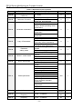
The symbols in the function code table are described as follows:
"△ " means the value of this parameter can be modified in stop and running status of drive;
"×" means the value of this parameter cannot be modified when drive is running;
"⊙" means this parameter is a measured value that cannot be modified;
Default: The value when restored to factory default. Neither measured parameter value nor
recorded value will be restored.
Setting Range: the scope of setting and display of parameters
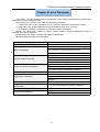
FR100 parameter groups are listed below:
Category
System Parameters
Parameter Group
F00: System Parameters
F01: Frequency Command
Basic Parameters
F02: Start/Stop Control Start/Stop Control
Input & Output Terminals
Motor and Control Parameters
Protection Parameters
Application Parameters
Communication Parameters
Keys and Display of Keypad
Parameters
User-defined Display Parameters
Monitoring Parameters
F03: Accelerate/Decelerate Parameters
F04: Digital Input
F05: Digital Output
F06: Analog and Pulse Input
F07: Analog and Pulse Output
F08: Parameters of Motor 1
F09: V/f Control Parameters of Motor 1
F10: Vector Control Parameters of Motor 1
F11: Protection Parameters
F12: Multi-Reference and Simple PLC Function
F13: Process PID
F14: Swing Frequency, Fixed Length , Count and
Wakeup
F15: Communication Parameters
F16:Keys and Display of Keypad Parameters
F17:User-defined Display Parameters
U00:Status monitoring
U01:Fault record
- 31 -
FR100 Series Multifunctional Compact Inverter
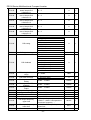
5.1 Standard Function Parameters
Table 5-1 Standard Function Parameters
Param.
Parameter Name
Group F00: System Parameters
Setting of User
F00.00
Password
F00.02
Parameter Protection
F00.04
Parameter Initialization
F00.05
Copy of Parameters
F00.06
Parameter
editing mode
F00.08
Motor 1 control mode
F00.09
DI7/HI input mode
F00.12
PWM optimization
F00.13
Carrier frequency
F00.14
F00.15
Upper carrier
frequency
Lower carrier
frequency
Setting Range
0~65535
0: All parameter programmable
1: Only F00.02 and this
parameter programmable
0: No operation
1: Restore all parameters to
factory default (excluding motor
parameters)
2: Clear fault record
3: Restore user backup
parameters
4: Back up currentuser
parameters
0: No operation
1: Upload parameter
2: Download parameter
(excluding motor parameters)
3: Download parameter
(including motor parameters)
0:Editable via keypad and
RS485
1:Editable via keypad
2:Editable via RS485
0: Voltage/Frequency (V/F)
control
1:Sensor-less vector control 1
2: Sensor-less vector control 2
0:Digital input terminal 7
1: Pulse input
Unit's place: PWM modulation
mode
0: Fixed carrier
1: Random carrier
2: Derating of fixed carrier
3: Derating of random carrier
Decade: PWM modulation mode
0: Seven-segment mode
1: Five-segment mode
2: Five-segment and
seven-segment automatic
switchover
Hundreds place: over-modulation
adjustment
0: Disabled
1: Enabled
0.700~16.000kHz
0.700~16.000kHz
0.700~16.000kHz
- 32 -
Default
Attr
0
×
0
×
0
×
0
×
0
×
1
×
0
×
000
×
Model
defined
8.000k
Hz
2.000k
Hz
△
×
×
FR100 Series Multifunctional Compact Inverter
F00.16
Output voltage
5.0~100.0%
0: Disabled
1: Enabled
2: AVR is disabled if the DC
bus voltage > the rated
voltage of DC bus, and it will be
enabled if the DC bus
voltage≤the rated voltage of DC
bus.
0: Run at power-on
1: Fan working during running
0~65535
F00.17
AVR
F00.18
Fan control
F00.19
Factory password
F00.20
Inverter rated power
0.20~400.00kW
F00.21
Inverter rated voltage
60~660V
F00.22
Inverter rated current
0.1~1500.0A
F00.23
Software version
0.00~655.35
100.0%
×
0
×
1
×
0
Model
defined
Model
defined
Model
defined
Model
defined
×
⊙
⊙
⊙
⊙
Group F00: Frequency Command
F01.00
Frequency source
selection
F01.01
Master Frequency
Command Source
F01.02
Digital Setting of Master
Frequency
0: Master frequency source
1: Auxiliary frequency source
2: Master +Auxiliary
3: Master - Auxiliary
4: MAX{Master, Auxiliary }
5: MIN {Master, Auxiliary }
6: AI1*( Master + Auxiliary)
7: AI2*( Master +Auxiliary)
0:Master digital setting (F01.02)
1: keypad potentiometer
2: Analog input AI1
3: Communication
4: Multi-reference
5: PLC
6: Process PID output
7: X7/HI pulse input
8:AI2
8: Analog input AI2
9:AI3
9: Analog input AI3
0.00~Fmax
F01.03
Auxiliary Frequency
Command Source
0: Auxiliary digital setting
(F01.04)
1: keypad potentiometer
2: Analog input AI1
3: Communication
4: Multi-reference
5: PLC
6: Process PID output
7: X7/HI pulse input
8: Analog input AI2
9: Analog input AI3
F01.04
Digital setting of
auxiliary frequency
0.00~Fmax
- 33 -
0
×
1
×
0.00Hz
△
0
×
0.00Hz
△
FR100 Series Multifunctional Compact Inverter
F01.07
F01.08
Range of auxiliary
frequency
Coeff of auxiliary
frequency
Jog frequency
Maximum frequency
F01.09
Upper limit frequency
F01.10
Lower limit frequency
F01.05
F01.06
Operation when command
frequency lower than
lower limit frequency
Lower limit frequency
F01.12
running time
Group F02: Start/Stop Control
F01.11
F02.00
Run command
F02.01
Running direction
F02.02
Reverse-proof action
F02.03
Dead time between
forward and reverse
F02.04
Start mode
F02.05
F02.07
F02.08
F02.09
F02.10
F02.11
Start frequency
Startup frequency holding
time
Startup DC brakin current
DC braking time at start
Speed search current
Sped search decel time
Sped search coefficient
F02.12
Stop mode
F02.06
F02.16
Initial frequency of stop
DC braking
Stop DC braking current
Waiting time of stop DC
braking
Stop DC braking time
F02.17
Dynamic brake
F02.13
F02.14
F02.15
Dynamic Brake
Voltage
F02.19
Brake use ratio
Group F03: Accel/Decel Parameters
F03.00
Accel time 1
F02.18
0: Relative to maximum frequency
1: Relative to master frequency
0
×
0.0~150.0%
100.0%
△
0.00~Fmax
20.00~600.00Hz
Fdown~Fmax
Lower limit frequency~maximum
frequency
0.00~Fup
0: Run at lower limit frequency
1: Run at 0 Hz would be activated
after the time delay set by F01.12
5.00Hz
50.00Hz
△
×
50.00Hz
×
0.00Hz
×
0
×
60.0s
×
0
×
0
△
0
×
0.0s
×
0
×
0.00Hz
×
0.0s
×
0.0~150.0%
0.0~100.0s
0.0~180.0%
0.0~10.0s
0.01~5.00
0: Ramp to stop
1: Coast to stop
0.0%
0.0s
100.0%
1.0s
0.30
×
×
△
×
△
0
×
0.01~50.00Hz
2.00Hz
×
0.0~150.0%
0.0%
×
0.0~30.0s
0.0s
×
0.0~30.0s
0: Disabled
1: Enabled
2: Enabled at running
3: Enabled at deceleration
0.0s
×
0
×
90.0~150.0%
128.0%
×
5.0~100.0%
100.0%
×
0.0~6000.0s
15.0s
△
0.0~6000.0s
0: Keypad control (LED off)
1: Terminal control (LED on)
2: Communication control (LED
blinking)
0: Forward
1: Reverse
0: Reverse enabled
1: Reverse disabled
0.0~6000.0s
0: From start frequency
1: Rotational speed tracking restart
0.00~10.00Hz
0.0~100.0s
- 34 -
FR100 Series Multifunctional Compact Inverter
F03.01
F03.02
F03.03
F03.04
F03.05
F03.06
F03.07
F03.08
F03.09
Decel time 1
Accel time 2
Decel time 2
Accel time 3
Decel time 3
Accel time 4
Decel time 4
Jog accel time
Jog decel time
F03.10
Accel/Decele curve
F03.11
S curve Time
Frequency switchover
point
F03.13
between acceleration time
1
and acceleration time 2
Frequency switchover
point
F03.14
between deceleration time
1
and deceleration time 2
Group F04 Digital Input
F04.00
Function of terminal DI1
F04.01
Function of terminal DI2
F04.02
Function of terminal DI3
F04.03
Function of terminal DI4
F04.06
Function of terminal D17
15.0s
15.0s
15.0s
15.0s
15.0s
15.0s
15.0s
15.0s
15.0s
△
△
△
△
△
△
△
△
△
0
×
0.0s
×
0.00~Fmax
0.00Hz
×
0.00~Fmax
0.00Hz
×
0.0~6000.0s
0.0~6000.0s
0.0~6000.0s
0.0~6000.0s
0.0~6000.0s
0.0~6000.0s
0.0~6000.0s
0.0~6000.0s
0.0~6000.0s
0: Linear Accel/Decel
1: S-curve Accel/Decel
0.0~6000.0s
0: No function
1: Running forward (FWD)
2: Running reverse (REV)
3: Three-wire control
4: JOG forward
5: JOG reverse
6: Coast to stop
7: Fault reset (RESET)
8: Running suspended
9: External fault input
10: Terminal UP
11: Terminal DOWN
12: UP/DOWN (including ∧/∨
key) adjustment clear
13: Multi-step frequency terminal 1
14: Multi-step frequency terminal 2
15: Multi-step frequency terminal 3
16: Multi-step frequency terminal 4
17: Accel/Decel time determinant 1
18: Accel/Decel time determinant 1
19: Accel/Decel disabled(ramp
stop not inclusive)
20: Switch to auxiliary speed
setting
21: PLC status reset
22: Simple PLC paused
23: Simple PLC paused
24: PID adjustment direction
25: PID integration paused
26: PID parameter switch
27: Swing frequency pause(output
the currentfrequency)
- 35 -
1
2
7
13
0
0
0
0
0
×
×
×
×
×
×
×
×
×
0
×
FR100 Series Multifunctional Compact Inverter
28: Swing frequency reset(output
the central frequency)
29: Run command switched to
keypad contro
30: Run command switched to
terminal control
31: Run command switched to
communication control
32: Count input
33: Count clear
34: Length count
35: Length clear
36: DC brake input command at
stop
37~99:reserved
F04.10
F04.11
F04.12
Filtering time of digital
input terminalD11~D17
Delay time of terminal
DI1
Delay time of terminal
DI2
F04.13
Terminal DI1~DI4
positive/negative logic
F04.14
Terminal
DI7positive/negative logic
F04.15
FWD/REV terminal
control mode
F04.16
Terminal UP/DOWN
frequency adjustment
control
Terminal UP/DOWN
frequency change step
size
Group F05 Digital Output
F05.00
Y1 output function
F04.17
F05.02
Relay 1 output function
0.010s
△
0.0~300.0s
0.0s
△
0.0~300.0s
0.0s
△
00000
×
00000
×
0
×
000
×
1.00Hz/
200ms
△
1
2
×
×
11
×
0.000~1.000s
Reserved DI4、DI3、DI2、DI1
0: Positive logic(Terminals are on
at 0V/off at 24V)
1: Negative Logic (Terminals are
off at 0V/on at 24V)
Reserved DI7
0: Positive logic
1: Negative Logic
0: Two-wire mode 1
1: Two-wire mode 2
2: Three-wire mode 1
3: Three-wire mode 2
Unit's place: action when stop
0: Clear
1: Holding
Decade: action on power loss
0: Clear
1: Holding
Hundreds place: integral function
0: No integral function
1: Integral function enabled
0.00~50.00Hz
0.00:Disabled
0: No output
2: Fault output
3: Frequency-level detection FDT1
output
4: Frequency-level detection FDT2
output
5: Drive in 0Hz running 1(no output
at stop)
6: Drive in 0Hz running 2(output at
stop)
- 36 -
FR100 Series Multifunctional Compact Inverter
F05.04
F05.06
Y1 output delay time
R1 output delay time
F05.08
Enabled state of digital
output
Detection width of
frequency attained
F05.10
FDT1 upper bound
F05.11
FDT1 lower bound
F05.12
FDT2 upper bound
F05.13
FDT2 lower bound
Consecutive running
F05.14
time
Accumulative power-on
F05.15
time setting
Accumulative running
F05.16
time setting
Group F06 Analog and Pulse Input
Minimum input of curve
F06.00
AI1
Set value corresponding
F06.01
to minimum input of
curve AI1
F05.09
F06.02
F06.03
F06.04
F06.05
F06.06
Input of inflection point
1 of curve AI1
Set value corresponding
to input of inflection
point 1 of curve AI1
Input of inflection point
2 of curve AI1
Set value corresponding
to input of inflection
point 2 of curve AI1
Maximum input of curve
7: Upper limit frequency attained
8: Lower limit frequency attained
9: Frequency attained
10: Inverter is ready to work
11: Drive (motor) overloaded alarm
12: Inverter overheat warning
13: Current running time attained
14: Accumulative power-on time
attained
15: Consecutive running time
attained
16: PLC cycle completed
17: Set count value attained
18: Designated count value
attained
19: Length attained
0.0~6000.0s
0.0~6000.0s
Unit's place: Y1
0: Positive logic
1: Negative logic
Decade: Y2 (same as unit's place)
Hundreds place: Relay 1 output
(same as unit's place)
Thousands place: Relay 2 output
(same as unit's place)
0.0s
0.0s
△
△
0000
×
0.00~20.00Hz
5.00Hz
×
0.00~Fmax
0.00~Fmax
0.00~Fmax
0.00~Fmax
30.00Hz
30.00Hz
30.00Hz
30.00Hz
×
×
×
×
0.0Min
×
0.0~6000.0Min
0.0:Disabled
0~65535h
0:Disabled
0h
×
0~65535h
0:Disabled
0h
×
0.0%~input of inflection point1
of curve AI1
0.0%
△
-100.0~100.0%
0.0%
△
Minimum input of curve AI1 ~Input
of inflection point 2 of curve AI1
25.0%
△
-100.0~100.0%
25.0%
△
Input of inflection point 1 of curve
AI1~Maximum input of curve AI1
75.0%
△
-100.0~100.0%
75.0%
△
Input of inflection point 2 of curve
100.0%
△
- 37 -
FR100 Series Multifunctional Compact Inverter
F06.07
F06.08
F06.09
F06.10
F06.11
F06.12
F06.13
F06.14
F06.15
F06.24
F06.25
F06.26
F06.27
F06.28
F06.29
F06.31
AI1
Set value corresponding
to maximum input of
curve AI1
Minimum input of curve
AI2
Set value corresponding
to minimum input of
curve AI2
Input of inflection point
1 of curve AI2
Set value corresponding
to input of inflection
point 1 of curve AI2
Input of inflection point
2 of curve AI2
Set value corresponding
to input of inflection
point 2 of curve AI2
Maximum input of curve
AI2
Set value corresponding
to maximum input of
curve AI2
Minimum input of curve
keypad potentiometer
Set value corresponding
to minimum input of
curve keypad
potentiometer
Maximum input of curve
keypad potentiometer
Set value corresponding
to maximum input of
curve keypad
potentiometer
AI1 terminal filtering time
AI2 terminal filtering time
Keypad potentiometer
filtering time
AI1~100.0%
100.0%
△
0.0%~input of inflection point1 of
curve AI2
0.0%
△
-100.0~100.0%
0.0%
△
Minimum input of curve AI1 ~Input
of inflection point 2 of curve AI2
25.0%
△
-100.0~100.0%
25.0%
△
Input of inflection point 1 of curve
AI2~Maximum input of curve AI2
75.0%
△
-100.0~100.0%
75.0%
△
Input of inflection point A of curve
AI2~100.0%
100.0%
△
-100.0~100.0%
100.0%
△
0.0~Maximum input of curve
keypad potentiometer
0.1%
△
-100.0~100.0%
0.0%
△
Minimum input of curve keypad
potentiometer~100.0
99.9%
△
-100.0~100.0%
100.0%
△
0.000~10.000s
0.000~10.000s
0.100s
0.100s
△
△
0.000~10.000s
0.100s
△
0.00kHz
△
0.0%
△
50.00kHz
△
100.0%
△
0.100s
△
1
2
×
×
1
×
-100.0~100.0%
F06.32
Minimum input of curve HI
0.00 kHz~Maximum input of curve
HI
F06.33
Set value corresponding to
minimum input of curve HI
-100.0~100.0%
F06.34
Maximum input of curve HI
Minimum input of curve HI~
100.00kHz
Set value corresponding to
-100.0~100.0%
maximum input of curve HI
F06.36
HI terminal filtering time
0.000~10.000s
Group F07 Analog and Pulse Output
0: No output
1: Output frequency
F07.00
AO1 output function
2: Command frequency
3: Output current
4: Output voltage
F06.35
- 38 -
FR100 Series Multifunctional Compact Inverter
F07.03
AO1 offset
F07.04
AO1 gain
F07.05
AO1 filtering time
Group F08 Parameters of Motor 1
5: Output power
6: Bus voltage
7:+10V
8: keypad potentiometer
9:AI1
10:AI2
11:AI3
12:HI
13: Reserved
-100.0~100.0%
-2.000~2.000
0.000~10.000s
0.0%
1.000
0.000s
△
△
△
Model
defined
Model
defined
Model
defined
Model
defined
Model
defined
×
Model
defined
×
Model
defined
Model
defined
Model
defined
Model
defined
Model
defined
Model
defined
×
0.0~100.0
87%
×
0.0~100.0
75%
×
0.0~100.0
70%
×
0
×
0
×
F08.01
Power rating of motor 1
0.10~600.00kW
F08.02
Rated voltage of motor 1
60~660V
F08.03
Rated current of motor 1
0.1~1500.0A
F08.04
Rated frequency of
motor 1
20.00~Fmax
F08.05
Rated speed of motor 1
F08.06
Wiring mode of motor 1
F08.07
F08.08
F08.09
F08.10
F08.11
F08.12
F08.13
F08.14
F08.15
F08.30
Group F09
F09.00
Rated power factor of
motor 1
Stator resistance R1 of
async motor 1
Rotor resistance R2 of
async motor 1
Leakage inductance L1
of async motor 1
Mutual inductance L2 of
asynchronous motor 1
No-load current of
async motor 1
Field weakening coeff 1
of async motor 1
Field weakening coeff 2
of async motor 1
Field weakening coeff 3
of async motor 1
1~30000
0:丫
1:Δ
0.50~0.99
0.001~65.535Ω
0.001~65.535Ω
0.01~655.35mH
0.1~6553.5mH
0.1~1500.0A
0: No autotuning
1: Static autotuning of async motor
Autotuning of motor 1
2: Rotary autotuning of async
motor
V/f Control Parameters of Motor 1
0: Linear V/f
1: Multi-stage V/f
2: 1.2nd power V/F
V/f curve setting
3: 1.4th power V/F
4: 1.6th power V/F
5: 1.8th power V/F
6: 2.0nd power V/F
- 39 -
×
×
×
×
×
×
×
×
×
FR100 Series Multifunctional Compact Inverter
F09.01
Torque boost
Cut-off frequency of torque
boost
Multi-point V/F frequency
F09.03
1(F1)
Multi-point V/F voltage 1
F09.04
(V1)
Multi-point V/F frequency
F09.05
2(F2)
Multi-point V/F voltage 2
F09.06
(V2)
Multi-point V/F frequency
F09.07
3(F3)
Multi-point V/F voltage 3
F09.08
(V3)
Multi-point V/F frequency
F09.09
4(F4)
Multi-point V/F voltage 4
F09.10
(V4)
V/F slip compensation
F09.11
gain
Stator voltagedrop
F09.12
compensation gain
F09.13
Excitation boost gain
F09.14
Oscillation Suppression
Group F11 Protection Parameters
F09.02
F11.00
Current limit control
F11.01
Current limit
Frequency decreasing
time(limit current in
constant speed operation)
Current limit mode 2
proportion gain
Current limit mode 2
integral time
F11.02
F11.03
F11.04
F11.05
F11.06
F11.07
F11.08
F11.10
Overvoltage Stall Control
Overvoltage Stall
Voltage
Overvoltage Stall
Mode 2 Proportion Gain
Overvoltage Stall
Mode 2 Integral Time
Protection action 1
7: V/F complete separation
8: V/F half separation
0.1%–30.0% 0.0% (fixed torque
boost)
Model
defined
△
0.00~Fmax
50.00Hz
△
0.00~F09.05
0.00Hz
△
0.0%
△
0.00Hz
△
0.0%
△
0.00Hz
△
0.0%
△
F09.07~rated motor frequency
50.00Hz
△
0.0~100.0
100.0%
△
0.0~300.0%
0.0%
△
0.0~200.0%
100.0%
△
0.0~200.0%
0.0~300.0%
100.0%
0.0%
△
△
1
×
150.0%
×
0.0~6000.0s
5.0s
△
0.1~100.0%
3.0%
△
0.010s
△
1
×
130.0%
×
3.0%
△
0.000~1.000s
0.010s
△
Unit's place: Bus undervoltage
0: Fault reported and coast to stop
1: Stop according to the stop mode
2: Fault reported but continue to
run
3: Fault protection disabled
Ten's digit :Power input phase
00330
×
0.0~100.0
F09.03~F09.05
0.0~100.0
F09.05~F09.09
0.0~100.0
Ue=100.0%
0: Current limit disabled
1: Current limit mode 1
2: Current limit mode 2
100.0~200.0%
0.000~1.000s
0: Overvoltage stall disabled
1: Overvoltage stall mode 1
2: Overvoltage stall mode 2
120.0~150.0%
0.1~100.0%
- 40 -
FR100 Series Multifunctional Compact Inverter
F11.11
Protection action 2
F11.12
Protection action 3
F11.14
Frequency selection for
continuing to run upon
fault
F11.15
F11.17
Backup frequency upon
abnormality
Motor overload protection
time
F11.18
Overload alarm
F11.19
Overload alarm threshold
Overload alarm
activated time that
exceeding threshold
Inverter overheat warning
threshold
Detection level of power
F11.20
F11.21
F11.22
Loss (Err09)(Same as unit's
place )
Hundred's digit :Power output
phase loss(Err10)(Same as unit's
place )
Thousand's digit:Motor overload
(Err11)(Same as unit's place )
Ten thousand's digit:Inverter
overload(Err11)(Same as unit's
place )
External equipment fault(Err13)
0: Fault reported and coast to stop
1: Stop according to the stop mode
2: Fault reported but continue to
run
Ten's digit: EEPROM read/write
fault (Err15) (Same as unit's place)
Hundred's digit: Communication
overtime error (Err18) (Same as
unit's place)
Thousand's digit: PID feedback
loss (Err19) (Same as unit's place)
Ten thousand's digit: Continuous
running time reached (Err20)
(Same as unit's place)
Unit's place: Module temperature
detection disconnection(Err24)
0: Fault reported and coast to stop
1: Stop according to the stop mode
2: Fault reported but continue to
run
Ten's digit: Load becoming 0
(Err25) (Same as unit's place)
0: Current running frequency
1: Set frequency
2: Frequency upper limit
3: Frequency lower limit
4: Backup frequency upon
abnormality
00000
×
00000
×
0
×
0.00~Fmax
0.00Hz
×
30.0~300.0s
60.0s
×
00
×
130.0%
×
5.0s
×
50.0~100.0℃
70.0℃
×
5.0~100.0%
20.0%
×
Unit's place: detection option:
0: Always detect
1: Detect at constant speed only
Ten's digit : compared object
0: Rated current of motor
1: Rated current of drive
20.0~200.0%
0.1~60.0s
- 41 -
FR100 Series Multifunctional Compact Inverter
F11.23
F11.24
F11.25
F11.26
F11.27
F11.28
F11.29
loss
Detection time of power
loss
Action selection at
instantaneous power
failure
Decel time at
instantaneous power
failure
Rapid current limit
Times of automatic
reset
Interval of automatic
reset
DO action during fault auto
reset
5.0s
×
1
×
5.0s
△
0: Disabled
1: Enabled
0
×
0~20
0
×
1.0s
×
0
×
0.0%
0.0%
0.0%
0.0%
0.0%
0.0%
0.0%
0.0%
0.0%
0.0%
0.0%
0.0%
0.0%
0.0%
0.0%
0.0%
△
△
△
△
△
△
△
△
△
△
△
△
△
△
△
△
0
×
0000
×
0.1~60.0s
0: Disabled
1: Enabled
0.0~6000.0s
0.1~100.0s
0: Not act
1: Act
Group F12: Multi-Reference and Simple PLC Function
F12.00
Reference 0
-100.0~100.0%
F12.01
Reference 1
-100.0~100.0%
F12.02
Reference 2
-100.0~100.0%
F12.03
Reference 3
-100.0~100.0%
F12.04
Reference 4
-100.0~100.0%
F12.05
Reference 5
-100.0~100.0%
F12.06
Reference 6
-100.0~100.0%
F12.07
Reference 7
-100.0~100.0%
F12.08
Reference 8
-100.0~100.0%
F12.09
Reference 9
-100.0~100.0%
F12.10
Reference 10
-100.0~100.0%
F12.11
Reference 11
-100.0~100.0%
F12.12
Reference 12
-100.0~100.0%
F12.13
Reference 13
-100.0~100.0%
F12.14
Reference 14
-100.0~100.0%
F12.15
Reference 15
-100.0~100.0%
0: Digital setting(F12.00)
1:keypad potentiometer
2:AI1
F12.16
Reference 0 source
3: Process PID output
4: X7/HI pulse input
5:AI2
6:AI3
Unit's place: PLC running mode
0: Stop after a single cycle
1: Continue to run with the last
frequency after a single cycle
2: Repeat cycles
Running mode of simple
Decade: started mode
F12.17
PLC
0: Continue to run from the step of
stop (or fault)
1: Run from the first step
“multi-step frequency 0”
Hundreds place:power loss
memory
- 42 -
FR100 Series Multifunctional Compact Inverter
F12.18
F12.19
F12.20
F12.21
F12.22
F12.23
F12.24
F12.25
F12.26
F12.27
F12.28
F12.29
F12.30
F12.31
F12.32
F12.33
F12.34
F12.35
F12.36
F12.37
F12.38
F12.39
F12.40
F12.41
F12.42
F12.43
F12.44
Running time of step 0
Running time of step 1
Running time of step 2
Running time of step 3
Running time of step 4
Running time of step 5
Running time of step 6
Running time of step 7
Running time of step 8
Running time of step 9
Running time of step 10
Running time of step 11
Running time of step 12
Running time of step 13
Running time of step 14
Running time of step 15
Acceleration/deceleration
time of simple PLC
reference 0
Acceleration/deceleration
time of simple PLC
reference 1
Acceleration/deceleration
time of simple PLC
reference 2
Acceleration/deceleration
time of simple PLC
reference 3
Acceleration/deceleration
time of simple PLC
reference 4
Acceleration/deceleration
time of simple PLC
reference 5
Acceleration/deceleration
time of simple PLC
reference 6
Acceleration/deceleration
time of simple PLC
reference 7
Acceleration/deceleration
time of simple PLC
reference 8
Acceleration/deceleration
time of simple PLC
reference 9
Acceleration/deceleration
time of simple PLC
reference 10
0: Memory disabled on power loss
1: Memory enabled on power loss
Thousands place: unit of simple
PLC running time
0: Second (s)
1: Minute (min)
0.0~6000.0s(h)
0.0~6000.0s(h)
0.0~6000.0s(h)
0.0~6000.0s(h)
0.0~6000.0s(h)
0.0~6000.0s(h)
0.0~6000.0s(h)
0.0~6000.0s(h)
0.0~6000.0s(h)
0.0~6000.0s(h)
0.0~6000.0s(h)
0.0~6000.0s(h)
0.0~6000.0s(h)
0.0~6000.0s(h)
0.0~6000.0s(h)
0.0~6000.0s(h)
0.0s(h)
0.0s(h)
0.0s(h)
0.0s(h)
0.0s(h)
0.0s(h)
0.0s(h)
0.0s(h)
0.0s(h)
0.0s(h)
0.0s(h)
0.0s(h)
0.0s(h)
0.0s(h)
0.0s(h)
0.0s(h)
△
△
△
△
△
△
△
△
△
△
△
△
△
△
△
△
0~3
0
△
0~3
0
△
0~3
0
△
0~3
0
△
0~3
0
△
0~3
0
△
0~3
0
△
0~3
0
△
0~3
0
△
0~3
0
△
0~3
0
△
- 43 -
FR100 Series Multifunctional Compact Inverter
Acceleration/deceleration
timeof simple PLC
reference 11
Acceleration/deceleration
F12.46
time of simple PLC
reference 12
Acceleration/deceleration
F12.47
time of simple PLC
reference 13
Acceleration/deceleration
F12.48
time of simple PLC
reference 14
Acceleration/deceleration
F12.49
time of simple PLC
reference 15
Group F13 Process PID
F12.45
0~3
0
△
0~3
0
△
0~3
0
△
0~3
0
△
0~3
0
△
0
×
50.0%
△
0
×
1000
△
0
×
0.000~10.000s
0.000s
△
0.000~10.000s
0.000s
△
0.000~10.000s
0.000s
△
0.0~100.0
0.01~10.00s
0.000~10.000s
0.0~100.0%
PID output frequency lower limit~
100.0%(100.0% corresponds to
maximum frequency )
–100.0%~PID output frequency
lower limit
0.1~100.0%
20.0
2.00s
0.000s
1.0%
△
△
△
×
100.0%
×
0.0%
×
0.0%
×
0: F13.01 digital setting
1:keypad potentiometer
2:AI1
3: Communication
4:Multi-Reference
5: DI7/HI pulse input
6: AI2
7:AI3
0.0~100.0%
0:AI1
1:AI2
2: Communication
3:AI1+AI2
4:AI1-AI2
5:Max{AI1,AI2}
6:Min{AI1,AI2}
7: DI7/HI pulse input
8:AI3
F13.00
PID setting
F13.01
PID digital setting
F13.02
PID feedback
F13.03
PID setting feedback
range
0~60000
F13.04
PID action direction
0: Forward action
1: Reverse action
F13.05
F13.06
F13.07
F13.08
F13.09
F13.10
F13.17
F13.22
F13.23
F13.24
Filtering time of PID
setting
Filtering time of PID
feedback
Filtering time of PID
output
Proportional gain Kp1
Integration time Ti1
Differential time Td1
PID offset limit
PID output frequency
upper limit
PID output frequency
lower limit
Detection value of
- 44 -
FR100 Series Multifunctional Compact Inverter
F13.25
PID feedback loss
Detection time of
PID feedback loss
0.0%: Not judging feedback loss
0.0~30.0s
0: No PID operation at stop
1: PID operation at stop
Group F14: Swing Frequency, Fixed Length , Wakeup and Count
0: Relative to the setting
frequency
Swing frequency setting
F14.00
mode
1: Relative to the maximum
frequency
Swing frequency
F14.01
0.0~100.0%
amplitude
F14.02
Jump frequency amplitude
0.0~50.0%
Rising Time of Swing
F14.03
0.0~6000.0s
frequency
Dropping Time of Swing
F14.04
0.0~6000.0s
frequency
F14.05
Set length
0m~65535m
Number of pulses per
F14.06
0.1~6553.5
meter
0: Not stop
Command when the
F14.07
length attained
1: Stop
F14.08
Set count value
1~65535
F14.09
Designated count value
1~65535
Dormant frequency (F14.12)~
F14.10
Wakeup frequency
Fmax
F14.11
Wakeup delay time
0.0~6000.0s
F14.12
Dormant frequency
0.00~Wakeup frequency
F14.13
Dormant delay time
0.0~6000.0s
Group F15: Communication Parameters
0:4800bps
1:9600bps
2:19200bps
F15.00
Baud rate
3:38400bps
4:57600bps
5:115200bps
No check, data format (1-8-N-2) for
RTU
1: Even parity check, data format
(1-8-E-1) for RTU
F15.01
Data format
2: Odd Parity check, data format
(1-8-O-1) for RTU
3: No check, data format(1-8-N-1)
for RTU
F15.02
Local address
1~247
0: Broadcast address
F15.03
Communication timeout
0.0~60.0s
F15.04
Response time delay
0~200ms
0:The inverter is the slave
Master-slave
F15.05
Communication Mode
1:The inverter is the master
The Master
0: Set frequency
F15.06
Communication
1: Current running frequency
Sending Data
Group F16 Keys and Display of Keypad Parameters
F16.00
MF.K key setting
0: No function
F13.26
PID operation at stop
- 45 -
1.0s
×
0
×
0
×
0.0%
△
0.0%
△
5.0s
△
5.0s
△
1000m
×
100.0
×
0
×
1000
1000
×
×
0.00Hz
△
0.0s
0.00Hz
0.0s
△
△
△
1
×
0
×
1
0.0s
1ms
×
×
×
0
×
0
×
1
×
FR100 Series Multifunctional Compact Inverter
F16.01
Function of STOP/RST
key
F16.02
Keys locked option
LED displayed parameters
setting 1 on running status
LED displayed parameters
F16.04
setting 2 on running status
LED displayed parameters
F16.05
setting 3 on running status
LED displayed parameters
F16.06
setting 4 on running status
LED displayed parameters
F16.07
setting 1 on stop status
LED displayed parameters
F16.08
setting 2 on stop status
LED displayed parameters
F16.09
setting 3 on stop status
LED displayed parameters
F16.10
setting 4 on stop status
Group U00 Status Monitoring
U00.00
Running frequency
U00.01
Set frequency
U00.02
Output voltage
U00.03
Output current
U00.04
Output power
Estimated Motor
U00.05
Speed
U00.06
Bus voltage
U00.07
Synchronous Frequency
U00.08
PLC step
U00.09
Program Operation Time
U00.10
PID set
U00.11
PID feedback
Status of DI1~DI5 digital
U00.12
input terminal
Status of DI6~DI7 digital
U00.13
input terminal
Status of digital output
U00.14
terminal
U00.15
AI1 input
U00.16
AI2 input
Keypad potentiometer
U00.18
input
F16.03
1: Jog
2: Forward/reverse switchover
3: Run command sources shifted
0: STOP/RST key valid only when
under keypad control
1: STOP/RST key valid under any
run command source
0: Not locked
1: Full locked
2: Keys locked other than RUN,
STOP/RST
3: Keys locked other than
STOP/RST
4: Keys locked other than >>
0
×
0
×
0~99(correspond U00.00~U00.99)
0
△
0~99(correspond U00.00~U00.99)
1
△
0~99(correspond U00.00~U00.99)
2
△
0~99(correspond U00.00~U00.99)
3
△
0~99(correspond U00.00~U00.99)
1
△
0~99(correspond U00.00~U00.99)
6
△
0~99(correspond U00.00~U00.99)
15
△
0~99(correspond U00.00~U00.99)
16
△
0.00Hz
0.00Hz
0.0V
0.0A
0.0kW
⊙
⊙
⊙
⊙
⊙
0rpm
⊙
0~1200V
0.00~Fup
1~15
0.0~6000.0s(h)
0~60000
0~60000
0V
0.00Hz
1
0.0s(h)
0
0
⊙
⊙
⊙
⊙
⊙
⊙
DI5 DI4 DI3 DI2 DI1
00000
⊙
00
⊙
R2 R1 Y2 Y1
0000
⊙
0.0~100.0%
0.0~100.0%
0.0%
0.0%
⊙
⊙
0.0~100.0%
0.0%
⊙
0.00~Fup
0.00~Fmax
0~660V
0.0~3000.0A
-3000.0~3000.0kW
0~60000rpm
DI7 DI6
- 46 -
FR100 Series Multifunctional Compact Inverter
U00.19
U00.20
U00.23
HI input
AO1 output
Temperature of inverter
Accumulative power-on
U00.24
time
U00.25
Accumulative running time
Cumulative power-on
U00.26
time
U00.27
Cumulative running time
U00.28
Count value
U00.29
Length value
Group U01 Fault Record
U01.00
Code of the latest fault
U01.01
Running frequency
when the latest fault
occurred
0.00kHz
0.0%
0.0℃
⊙
⊙
⊙
0~65535min
0min
⊙
0~6553.5min
0.0min
⊙
0~65535h
0h
⊙
0~65535h
0~65535
0~65535m
0h
0
0m
⊙
⊙
⊙
0
⊙
0.00Hz
⊙
0.00~100.00kHz
0.0~100.0%
-40.0℃~120.0℃
0: No fault
Err01:Accel overcurrent
Err02:Decel overcurrent
Err03:Constant-speed overcurrent
Err04:Accel overvoltage
Err05:Decel overvoltage
Err06:Constant-speed overvoltage
Err07:Bus undervoltage
Err08:Short circuit
Err09:Power input phase loss
Err10:Power output phase loss
Err11:Motor overload
Err12:Inverter overload
Err13:External equipment fault
Err14:Module overheat
Err15:EEPROM read/write fault
Err16:Motor auto-tuning cancelled
Err17:Motor auto-tuning fault
Err18:Communication overtime
error
Err19:PID feedback loss
Err20:Continuous running time
reached
Err21:Parameter upload fault
Err22:Parameter download fault
Err23:Braking unit fault
Err24:Module temperature
detection disconnection
Err25: Load becoming 0
Err26:With-wave current limit fault
Err27:Inverter soft-start relay is off
Err28:Software version
compatibility fault
Err29:reserved
Err30:reserved
Err31:reserved
0.00~Fup
- 47 -
FR100 Series Multifunctional Compact Inverter
U01.02
U01.03
U01.04
U01.05
U01.06
U01.07
U01.08
U01.09
U01.10
U01.11
U01.12
U01.13
U01.14
Output current when the
latest fault occurred
Bus voltage when the
latest fault occurred
Cumulative running time
when the latest fault
occurred
Code of previous fault
Running frequency
when previous fault
occurred
Output current when
previous fault occurred
Bus voltage when
previous fault occurred
Cumulative running time
when previous fault
occurred
Before-previous fault
code
Running frequency
when before-previous
fault occurred
Output current when
before-previous fault
occurred
Bus voltage when
before-previous fault
occurred
Cumulative running time
when before-previous
fault occurred
0.0A
⊙
0~1200V
0V
⊙
0~65535h
0h
⊙
Same as U01.00
0
⊙
0.00Hz
⊙
0.0A
⊙
0~1200V
0V
⊙
0~65535h
0h
⊙
Same as U01.00
0
⊙
0.00Hz
⊙
0.0A
⊙
0~1200V
0V
⊙
0~65535h
0h
⊙
0.0~3000.0A
0.00~Fup
0.0~3000.0A
0.00~Fup
0.0~3000.0A
- 48 -
FR100 Series Multifunctional Compact Inverter
Chapter 6 Specification of Parameters
Group F00 System Parameters
F00.00
Setting of user password
Range: 0~65535
Default: 0
Setting of password:
A non-zero number could be set as a user password by entering this password into F00.00 and
pressing ENT key to confirm once, the password setting will take effect as long as there is no
operation on keypad within 2 minutes, or cutting the power off and power up again . After a password
has been set and taken effect, you must enter the correct password in order to enter the menu. If the
entered password is incorrect you cannot view or modify parameters.
Change password:
Access F00.00 after entering the original password (at this point, F00.00 displays setting of user
password) and set the new password following the above-noted procedure.
Password clearance:
Access F00.00 after entering the original password (at this point, F00.00 displays setting of user
password); F00.00 is set to 0 and press ENT key to make confirmation. In this way, password is
successfully cleared and the password protection function is disabled.
F00.02
Parameter protection
Range: 0~1
Default: 0
0: All parameter programming allowed
1: Only this parameter programming allowed
F00.04
Parameter initialization
Range:0~4
Default: 0
0: No operation
1: Restore all parameters to factory default (excluding motor parameters)
If F00.04 is set to 1, most function codes are restored to the default settings except motor
parameters, fault records, accumulative running time, and accumulative power-on time.
2: Clear fault record
If F00.04 is set to 2, all fault record of Group U01 will be cleared.
3: Back up current user parameters
If F00.04 is set to 3, the current parameter settings are backed up, helping you to restore the
setting if incorrect parameter setting is performed.
4: Restore all parameters to backup parameters
If F00.04 is set to 4, the previous backup user parameters are restored.
F00.05
Copy of parameter
Range:0~3
Default: 0
0: No operation
1: Upload all parameters other than Group U to UP/DOWNLOAD
2: Download all parameters of UP/DOWNLOAD other than F08~F09 to drive
3: Download all parameters of UP/DOWNLOAD to drive
*:UP/DOWNLOAD is optional parts
F00.06
Parameter editing mode
Default: 0
Range:0~2
0: Editable via keypad and RS485
1: Editable via keypad
2: Editable via RS485
F00.08
Motor 1 control mode
Range:0~1
Default:0
0: V/f control
Constant voltage&frequency ratio control. Applicable to such cases in which the performance
Requirement to the drive is not rigorous, or using one drive to drive several motors, or it is difficult to
identify motor parameters correctly, etc. When motor 1 under V/f control is selected, need to set
related parameters Group F09 well.
1: Sensor-less vector control 1
This helps achieve high-performance control without encoder and provides strong adaptability of
load. Under this selection, please correctly set parameters Group F08 and F09.
F00.09
DI7/HI input mode
Default: 0
Range:0~1
0: Digital input terminal 7
1: Pulse input
- 49 -
FR100 Series Multifunctional Compact Inverter
F00.12
PWM optimization
Range:000~103
Default:000
Unit's place: PWM modulation mode
0: Fixed carrier
Carrier of inverter is a fixed value set by F00.12.
1: Random carrier
Inverter carrier will vary with output frequency in linear variation. Upper/Lower carrier frequencies
are under control of F00.14 and F00.15.
2: Derating of fixed carrier
Inverter can adjust carrier value based on F00.12, carrier temperature and carrier current,
protecting itself against overtemperature.
3: Derating of random carrier
Inverter can adjust carrier value based on random carrier, carrier temperature and carrier current,
protecting itself against overtemperature.
Decade: PWM modulation mode
0: Seven-segment mode
Hundreds place: over-modulation adjustment
0: Disabled
1: Enabled
At low grid voltage or long-term heavy-duty operation, over-modulation can improve the voltage
utilization and enhance the maximum voltage output capacity of the drive. This parameter takes effect
only for V/f control, while over-modulation is enabled all the time under SVC pattern.
Default: Model
F00.13
Carrier frequency
Range:0.700~16.000kHz
defined
At lower carrier frequency, output current of the drive produces higher harmonics, motor loss
increases, and temperature and motor noise rise, but drive temperature, drive leakage current, and
drive interference to external devices are lower or less.
With higher carrier frequency, drive temperature will rise, drive leakage current is bigger, and
drive interference to external devices is bigger. However, motor loss and noise will be lower, and
motor temperature will drop.
PWM carrier frequency setting method:
1) When the motor line is too long, reduce carrier frequency.
2) When torque at low speed is unstable, reduce carrier frequency.
3) If the drive produces severe interference to surrounding equipment, reduce carrier frequency.
4) Leakage current of the drive is big, reduce carrier frequency.
5) Drive temperature rise is relatively high, reduce carrier frequency.
6) Motor temperature rise is relatively high, increase carrier frequency.
7) Motor noise is relatively big, increase carrier frequency.
ATTENTION:
Increasing carrier frequency can reduce motor noise and heat, but it will increase temperature of
inverter. When the carrier frequency is higher than the default, inverter rated power shall be decreased
by 5% for every additional 1 kHz carrier frequency.
F00.14
Upper carrier frequency
Range:0.700~16.000kHz
Default:8.000 kHz
F00.15
Lower carrier frequency
Default:2.000 kHz
Range:0.700~16.000kHz
Inverter carrier will vary with output frequency in linear variation. Upper/Lower carrier frequencies
are under control of F00.14 and F00.15.
F00.16
Output voltage
Range:5.0~100.0%
Default:100.0%
Adjust the percentage of output voltage to input voltage.
F00.17
AVR
Default: 0
Range:0~2
0: Disabled
1: Enabled
2: AVR is disabled if the DC bus voltage > the rated voltage of DC bus, and it will be enabled if the
DC bus voltage≤the rated voltage of DC bus.
F00.18
Fan control
Range:0~1
Default:1
After power is on, the fan runs per the control mode after running for 2 minutes regardless of the
working status of inverter.
0: The fan runs directly after inverter is power-on.
1: the fan works when the AC drive is in running state. When the AC drive stops, the cooling fan
- 50 -
FR100 Series Multifunctional Compact Inverter
works if the heat sink temperature is higher than 42°C, and stops working if the heat sink temperature
is lower than 38°C.
F00.19
Factory password
Range:0~65535
Default: 0
Factory parameter
Default: Model
F00.20
Inverter rated power
Range:0.20~400kW
defined
Default: Model
F00.21
Inverter rated voltage
Range:220~380V
defined
Default: Model
F00.22
Inverter rated current
Range:0.1~1500.0A
defined
Default: Model
F00.23
Software version
Range:0.01~99.99
defined
The parameters are only for reference and cannot be edited.
Group F00 Frequency command
Fig. 6-1
Frequency source
F01.00
Range:0~7
Default: 0
selection
0: Master frequency source
The frequency source is determined by master frequency source F01.01.
1: Auxiliary frequency source
The frequency source is determined by auxiliary frequency source F01.03.
2: Master + Auxiliary
The frequency source is determined by Master + Auxiliary.
3: Master - Auxiliary
The frequency source is determined by Master - Auxiliary.
4: MAX {Master, Auxiliary}
The frequency source is determined by MAX {Master, Auxiliary}.
5: MIN {Master, Auxiliary}
The frequency source is determined by MIN {Master, Auxiliary}.
6: AI1*(Master + Auxiliary)
The frequency source is determined by AI1*(Master + Auxiliary).
7: AI2*(Master + Auxiliary)
The frequency source is determined by AI2*(Master + Auxiliary).
F01.01
Master frequency source selection
Default:1
Range:0~8
0: Digital setting (F01.02)
When the inverter is powered on, the value of F01.02 is taken as the master frequency source.
1: Keypad potentiometer
- 51 -
FR100 Series Multifunctional Compact Inverter
2: Analog input AI1
AI1 and AI2 are (0~10V) voltage input and (0~20mA) current input programmable. Voltage or
current input can be selected through toggle switches AI1 and AI2 on control board.
3: Communication
Upper computer is the master frequency command source of the drive through standard RS485
communication interface on the drive. Refer to Group F15 and appendix on this manual for further
information aboutcommunication protocol, and programming, etc.
4: Multi-reference
In multi-reference mode, combinations of different DI terminal states correspond to different set
frequencies. The FR100 supports a maximum of 16 speeds implemented by 16 state combinations of
four DI terminals (allocated with functions 13 to 16) in Group F04. The multiple references indicate
percentages of the value of F01.08 (Maximum frequency).
If a DI terminal is used for the multi-reference function, you need to perform related setting in
group F04.
5: PLC
Master frequency command is determined by simple PLC. See parameter Group F12 for details.
6: Process PID output
Master frequency command is determined by process closed-loop PID computation result. See
parameter Group F13 for details.
7: DI7/HI pulse input
If this parameter value selected, command frequency will be determined by pulse frequency input
via terminal DI7/HI only. In such a case, F00.09 should be set to 1. Corresponding relation between
pulse frequency and command frequency is specified in F06.32~F06.35.
8:AI2
Master frequency command is determined by analog input AI2.
Note:
AI2 are(0~10)V voltage input or (0~20) mA current input optional for AI2. Voltage or current input
can be selected by the toggle switch on control panel input and(0~20mA), correspondence between
analog value and frequency please refer to the specific instructions of function codeF06.00~F06.15.
When using external analog directly input, the connection diagram of voltage/current analog input
shown as figure 6-2.
Figure 6-2 Diagram for analog input with external power supply
When using the inverter with 10V power built-in combined with potentiometer, connection diagram
shown as figure 6-3, note that the toggle switch must keep voltage input side at this moment.
Figure 6-3 Diagram for internal 10V power analog input
- 52 -
FR100 Series Multifunctional Compact Inverter
Note:
The final set frequency of FR100 series inverter mainly frequency can be stacked by keypad
UP/DOWN button or the function of UP/DOWN terminal, while no such a function for the final setted
frequency of auxiliary frequency source.
Digital setting of master
Range:0.00~FmaxHz
Default:0.00Hz
frequency
When master frequency source selection F01.01 is set to 1, this parameter value will be the initial
value of master frequency command.
Auxiliary frequency command
F01.03
Range:0~9
Default: 0
source
0: Digital setting (F01.04)
When the inverter is powered on, the value of F01.02 is taken as the master frequency source.
1: Keypad potentiometer
Auxiliary frequency command is determined by keypad potentiometer.
2: Analog input AI1
Auxiliary frequency command is determined by analog input AI1.
3: Communication
Upper computer is the auxiliary frequency command source of the drive through standard RS485
communication interface on the drive.
4: Multi-reference
Auxiliary frequency command is determined by multi-reference. See parameter Group F04 for
details.
5: PLC
Auxiliary frequency command is determined by simple PLC. See parameter Group F12 for details.
6: Process PID output
Auxiliary frequency command is determined by process PID computation result. See parameter
Group F13 for details.
7: DI7/HI pulse input
Auxiliary frequency command is determined by DI7/HI pulse input.
8:AI2
Auxiliary frequency command is determined by analog input AI2.
Digital setting of auxiliary
F01.04
Range:0.00~Fmax
Default:0.00Hz
frequency
When auxiliary frequency command F01.03 is set to 0, this parameter value should be the initial
value of auxiliary frequency command.
F01.05
Range of auxiliary frequency
Default: 0
Range:0~1
0: Relative to maximum frequency
1: Relative to master frequency
See F01.06 specification for details.
F01.06
Coeff of auxiliary frequency
Range:0.0~150.0%
Default:100.0%
F01.05 and F01.06 will determine the final output value of auxiliary frequency command.
When F01.05 is set to 0 (relative to maximum frequency):
The auxiliary frequency= the auxiliary frequency *F01.06.
When F01.05 is set to 1 (relative to master frequency):
The setting range of the auxiliary frequency varies according to the master frequency.
The auxiliary frequency= the auxiliary frequency *F01.06*abs (the master frequency)/F01.08.
F01.07
Jog frequency
Range:0.00~Fmax
Default:5.00Hz
This parameter sets the running frequency during jog.
F01.08
Maximum frequency
Range:20.00~600.00
Default:50.00Hz
Maximum frequency of F01.08 is the maximum allowable output frequency of drive.
F01.09
Upper limit frequency
Range:Fdown~Fmax
Default:50.00Hz
F01.10
Lower limit frequency
Range:0.00~Fup
Default:50.00Hz
F01.09upper limit frequency is the user-defined maximum allowable running frequency; F01.10
lower limit frequency is user-defined minimum allowable running frequency.
ATTENTION:
1. Fup and Fdown shall be set as per motor nameplate parameters and working conditions. Motor
F01.02
- 53 -
FR100 Series Multifunctional Compact Inverter
shall not work in low frequency for a long time. Otherwise, motor service lifespan will be shortened due
to overheating.
2. Correlation of Fmax, Fup and Fdown: 0.00Hz ≤Fdown ≤Fup≤Fmax ≤600.00Hz
Operation when command
F01.11
frequency lower than lower
Range:0~1
Default: 0
limit frequency
Lower limit frequency
F01.12
Range:0.0~6000.0s
Default:0.0s
running time
0: Run at lower limit frequency
In case command frequency is lower than lower limit frequency, the running should be at lower
limit frequency.
1: Run at 0 Hz would be activated after the time delay
If frequency command is lower than lower limit frequency, run at 0 Hz would be activated after the
time delay set by F01.12. When lower limit frequency is 0, this limitation is invalid.
Group F02 Start/Stop Control Start/Stop Control
F02.00
Run command
Range:0~2
Default: 0
This parameter sets run command source. Run commands include "start, stop, forward ,
reverse,jog", etc.
0: Keypad control (LED off)
Control run command through RUN, STOP/RESET and MF.K keys on keypad (set multifunction
key MF.K to JOG by F16.00). Refer to Chapter 4 about the operation of keypad.
1: Terminal control (LED on)
Controls run command via DI terminals. Perform FORWARD and REVERSE by DI terminals. The
control modes are two-wire mode and three-wire mode selectable. See Group F04 for details of
designation and wiring regulation of DI terminals.
2: Communication control (LED blinking)
Master device is able to control run command through built-in RS485 serial communication
interface of drive. Refer to parameters Group F15 and appendix for further information about
programming.
Run command from keypad, terminals and communication can be switched by terminals "run
command switched to keypad control", "run command switched to terminal control" and "run command
switched to communication control".
Multifunction key MF.K can be set to "run command sources shifted" key through parameter
F16.00. When MF key is pressed under this setting; run command will be shifted during keypad control,
terminal control and communication control circularly.
F02.01
Running direction
Default: 0
Range:0~1
0: Forward
1: Reverse
You can change the rotation direction of the motor just by modifying this parameter without
changing the motor wiring. Modifying this parameter is equivalent to exchanging any two of the motor's
U, V, W wires.
Note:
The motor will resume running in the original direction after parameter initialization. Do not use
this function in applications where changing the rotating direction of the motor is prohibited after
system commissioning is complete.
F02.02
Reverse-proof action
Default: 0
Range:0~1
0: Reverse enabled
1: Reverse disabled
In some applications, reverse is likely to result in equipment damage. This parameter is used to
prevent reverse running.
Dead time of forward and
F02.03
Range:0.0~6000.0s
Default:0.0s
reverse
The dead time with 0Hz output during the transition from forward to reverse, or from reverse to forward. As shown
in Fig. 6-4.
- 54 -
FR100 Series Multifunctional Compact Inverter
Fig. 6-4
F02.04
Start mode
Default: 0
Range:0~1
0: From start frequency
If the DC braking time ( F02.08 ) is set to 0, the AC drive starts to run at the startup
frequency(F02.05) and keeps this frequency for a period of time set by F02.06, and then accelerated
to command frequency in accordance with the accel method and time..
If the DC braking time (F02.08)is not 0, the AC drive performs DC braking first and then starts to
run at the startup frequency. It is applicable to small-inertia load application where the motor is likely to
rotate at startup.
1: Rotational speed tracking restart
The AC drive judges the rotational speed and direction of the motor first and then starts at the
tracked frequency. Such smooth start has no impact on the rotating motor. It is applicable to the restart
upon instantaneous power failure of large-inertia load. To ensure the performance of rotational speed
tracking restart, set the motor parameters correctly.
F02.05
Start frequency
Range:0.00~10.00Hz
Default:0.00Hz
F02.06
Startup frequency holding time
Default:0.0s
Range:0.0~100.0s
To ensure the motor torque at AC drive startup, set a proper startup frequency. In addition, to build
excitation when the motor starts up, the startup frequency must be held for a certain period.
The startup frequency (F02.05) is not restricted by the frequency lower limit. If the set target
frequency is lower than the startup frequency, the AC drive will not start and stays in the standby state.
During switchover between forward rotation and reverse rotation, the startup frequency holding
time is disabled. The holding time is not included in the acceleration time but in the running time of
simple PLC.
F02.07
Startup DC braking current
Default:0.0
Range:0.0~150.0%
F02.08
Startup DC braking time
Default:0.0
Range:0.0~100.0s
Startup DC braking is generally used during restart of the AC drive after the rotating motor stops.
Pre-excitation is used to make the AC drive build magnetic field for the asynchronous motor before
startup to improve the responsiveness.
Startup DC braking is valid only for direct start (f02.05 = 0). In this case, the AC drive performs DC
braking at the set startup DC braking current. After the startup DC braking time, the AC drives starts to
run. If the startup DC braking time is 0, the AC drives starts directly without DC braking. The larger the
startup DC braking current is, the larger the braking force is.
F02.09
Speed search current
Default:100.0%
Range:0.0~180.0
100% corresponds to rated current of the drive. When output current of drive is less than this
parameter value, it will be deemed that the output frequency of drive has been kept in step with motor
speed and the search action finished.
F02.10
Sped search decel time
Range:0.0~10.0
Default:1.0s
This parameter sets the output frequency Decel time of speed search action. This time means the
time required for Decel from maximum frequency to 0.The shorter the speed search Decel time is, the
faster the search will be. However, excessively rapid search may bring about inaccuracy of search
result.
F02.11
Sped search coefficient
Range:0.01~5.00
Default:0.30
Sped search coefficient
F02.12
Stop method
Range:0~1
Default: 0
- 55 -
FR100 Series Multifunctional Compact Inverter
0: Ramp to stop
Upon the receipt of stop command, drive will gradually decrease output frequency according to
the set Decel time, and stop when frequency attains 0.
1: Coast to stop
Upon the receipt of stop command, drive will immediately lock the output and the motor will stop
with its mechanical inertia.
Initial frequency of stop DC
F02.13
Range:0.00~50.00Hz
Default:2.00Hz
braking
F02.14
Stop DC braking current
Range:0.0~150.0%
Default:0.0%
Waiting time of stop DC
F02.15
Range:0.0~30.0s
Default:0.0s
braking
F02.16
Stop DC braking time
Range:0.0~30.0s
Default:0.0s
Initial frequency of stop DC braking:
During the process of decelerating to stop, the AC drive starts DC braking when the running
frequency is lower than the value set in F02.13.
Stop DC braking current:
This parameter specifies the output current at DC braking and is a percentage relative to the base
value.
If the rated motor current is less than or equal to 80% of the rated AC drive current, the base value
is the rated motor current.
If the rated motor current is greater than 80% of the rated AC drive current, the base value is 80%
of the rated AC drive current.
Waiting time of stop DC braking:
When the running frequency decreases to the initial frequency of stop DC braking, the
AC drive stops output for a certain period and then starts DC braking. This prevents faults such as
over current caused due to DC braking at high speed.
Stop DC braking time:
This parameter specifies the holding time of DC braking. If it is set to 0, DC braking is cancelled.
ATTENTION:
If there is a DC brake signal of external terminal at stop, then the DC brake time takes the bigger
value between the active time of the terminal and the setting time of F02.16.
The stop DC braking process is shown in the following figure.
Figure 6-5 Stop DC braking process
Fig. 6-5
F02.17
Dynamic brake
Default: 0
Range:0~3
When dynamic brake is enabled, the electric energy generated during Decel shall be converted
into heat energy consumed by brake resistor, so as to attain rapid Decel. This brake method applies to
- 56 -
FR100 Series Multifunctional Compact Inverter
brake of high-inertia load or the situations that require quick stop. In such a case, it is necessary to
select appropriate dynamic brake resistor and break unit. The AC drives equal and below 30kW is
provided with a standard built-in brake unit. Built-in brake unit is optional for AC drive 37kW~75kW.
0: Disabled
1: Enabled
2: Enabled at running
3: Enabled at deceleration
Dynamic brake threshold
F02.18
Range:90.0~150.0%
Default:128.0%
voltage
This parameter takes effect only to the drives with built-in brake unit.
When bus voltage of AC drive attains the value of F02.18, dynamic brake shall perform. The
energy shall be rapidly consumed through brake resistor. This value is used to regulate the brake
effect of brake unit.
F02.19
Brake use ratio
Range:5.0~100.0%
Default:100.0%
It is valid only for the AC drive with internal braking unit and used to adjust the duty ratio of the
braking unit. The larger the value of this parameter is, the better the braking result will be. However,
too larger value causes great fluctuation of the AC drive bus voltage during the braking process.
Group F03 Accel/Decel Parameters
F03.00
Accel time 1
Range:0.0~6000.0s
Default:15.0s
F03.01
Decel time 1
Default:15.0s
Range:0.0~6000.0s
F03.02
Accel time 2
Range:0.0~6000.0s
Default:15.0s
F03.03
Decel time 2
Range:0.0~6000.0s
Default:15.0s
F03.04
Accel time 3
Range:0.0~6000.0s
Default:15.0s
F03.05
Decel time 3
Range:0.0~6000.0s
Default:15.0s
F03.06
Accel time 4
Range:0.0~6000.0s
Default:15.0s
F03.07
Decel time 4
Range:0.0~6000.0s
Default:15.0s
Accel time means required time for drive to Accelerate to maximum frequency F01.08 from zero
frequency, while Decel time refers to the time required for drive to Decelerate to zero frequency from
maximum frequency F01.08.
These four types of Accel/Decel time can be selected through the ON/OFF combination of
DI terminals" Accel/Decel time determinant 1" and "Accel/Decel time determinant 2". See the following
table.
Accel/Decel time
Accel/Decel time
Accel/Decel time
determinant 2
determinant 1
OFF
OFF
Accel/Decel time 1(F03.00、F03.01)
OFF
ON
Accel/Decel time 2(F03.02、F03.03)
ON
OFF
Accel/Decel time 3(F03.04、F03.05)
ON
ON
Accel/Decel time 4(F03.06、F03.07)
F03.08
Jog accel time
Default:15.0s
Range:0.0~6000.0s
F03.09
Jog decel time
Range:0.0~6000.0s
Default:15.0s
F03.08 and F03.09 set the rate of Accel/Decel of Jog, similar with F03.00~F03.07.
F03.10
Accel/Decele curve
Range:0~1
Default: 0
F03.11
S curve Time
Default:0.0s
Range:0.0~6000.0s
0: Linear Accel/Decel
Accel/Decel is in linear mode.
1: S-curve Accel/Decel
The 1st section and the last section in accelerating or decelerating are in smooth transition. The
acceleration/deceleration curve is similar to S curve. When it is in S curve, the final
acceleration/deceleration time= S curve time+ Linear acceleration/deceleration time. See Figure 6-13
for 2 acceleration/deceleration modes.
See Figure 6-6 for 2 acceleration/deceleration modes.
- 57 -
FR100 Series Multifunctional Compact Inverter
Figure 6-6
Frequency switchover point
Range:0.00~Fmax
Default:0.00Hz
between acceleration time 1 and
acceleration time 2
Frequency switchover point
F03.14
between deceleration time 1 and
Range:0.00~Fmax
Default:0.00Hz
deceleration time 2
This function is valid when motor 1 is selected and acceleration/deceleration time switchover is
not performed by means of DI terminal. It is used to select different groups of acceleration/deceleration
time based on the running frequency range rather than DI terminal during the running process of the
AC drive.
During acceleration, if the running frequency is smaller than the value of F03.13, acceleration time
2 is selected. If the running frequency is larger than the value of F03.13, acceleration time 1 is
selected.
During deceleration, if the running frequency is larger than the value of F03.14, deceleration time
1 is selected. If the running frequency is smaller than the value of F03.14, deceleration time 2 is
selected.
Figure 6-7 Acceleration/deceleration time switchovers.
F03.13
Figure 6-7
- 58 -
FR100 Series Multifunctional Compact Inverter
Group F04 Digital Input
F04.00
F04.01
F04.02
F04.03
F04.06
Value
0
1
2
3
4
5
Function
Function
Function
Function
Function
of
of
of
of
of
terminal
terminal
terminal
terminal
terminal
Function
No function
Forward RUN
(FWD)
Reverse RUN
(REV)
Three-wire control
Forward JOG
(FJOG)
Reverse JOG
(RJOG)
6
Coast to stop
7
Fault reset (RESET)
8
RUN pause
9
Normally open (NO)
input
of external fault
10
Terminal UP
11
Terminal DOWN
12
UP and DOWN
setting
clear (terminal,
keypad)
13
14
15
16
17
18
Multi-reference
terminal 1
Multi-reference
terminal 2
Multi-reference
terminal 3
Multi-reference
terminal 4
Terminal 1 for
acceleration/
deceleration time
selection
Terminal 2 for
acceleration/
deceleration time
selection
DI1
DI2
DI3
DI4
DI7
Range:0~99
Range:0~99
Range:0~99
Range:0~99
Range:0~99
Default:1
Default:2
Default:7
Default:13
Default:0
Description
Set 0 for reserved terminals to avoid malfunction.
Terminals control forward running and reverse running of the
drive. Refer to F04.15 for enabled conditions on initial power
up.
The terminal determines three-line control of the AC drive. For
details, see the description of F04.15.
FJOG indicates forward JOG running, while RJOG indicates
reverse JOG running. The JOG frequency, acceleration time
and deceleration time are described respectively in F01.07,
F03.08 and F03.09.
The AC drive blocks its output, the motor coasts to rest and is
not controlled by the AC drive. It is the same as coast to stop
described in F02.12.
The terminal is used for fault reset function, the same as the
function of RESET key on the operation panel.Remote fault
reset is implemented by this function.
The AC drive decelerates to stop, but the running parameters
are all memorized, such as PLC, swing frequency and PID
parameters. After this function is disabled, the AC drive
resumes its status before stop.
If this terminal becomes ON, the AC drive reports Err13 and
performs the fault protection action. For more details, see the
description of F11.11.
If the frequency is determined by external terminals, the
Terminals with the two functions are used as increment and
decrement commands for frequency modification.
If the frequency source is master frequency source setting, the
terminalis used to clear the modification by using the
UP/DOWN function or the increment/decrement key on the
keypad, returning the set frequency to the value of master
frequency source setting.
The setting of 16 speeds or 16 other references can be
implemented through combinations of 16 states of these four
terminals.
Totally four groups of acceleration/deceleration time can be
selected through combinations of two states of these two
terminals.
- 59 -
FR100 Series Multifunctional Compact Inverter
19
Acceleration/Decele
ration
prohibited
When "Accel/Decel disabled" terminal is enabled, the drive
maintains the present output frequency and no longer
responds to the change of command frequency. But it will
still perform ramp-down stop when receiving stop command.
This terminal is disabled during normal ramp-down stop.
20
Switch to auxiliary
frequency source
setting
Switch integrated frequency source setting mode to auxiliary
frequency source setting mode.
21
PLC status reset
22
Simple PLC paused
23
PID pause
24
Reverse PID action
direction
25
PID integral pause
26
27
28
29
30
31
PID parameter
switchover
Swing frequency
pause(output the
current frequenc)
Swing frequency
reset(output the
central frequency)
Run comman
switched to keypad
control
Run comman
switched to terminal
control
Run comman
switched to
communication
control
32
Count input
33
Count clear
34
Length count
When simple PLC is running and this terminal is enabled. The
status (running time and step) of PLC will be cleared and the
output frequency is step 0. When this terminal is disabled
again, the drive resumes PLC running from step 0.
When simple PLC is running and this terminal is enabled, the
current PLC status (running time and step) will be memorized,
and the drive will run at 0Hz. When this terminal is disabled,
the drive restores its running from the memorized moment.
When this terminal is enabled, PID adjustment is paused, and
the drive will maintain current output frequency. After this
terminal becomes disabled, PID adjustment recovers.
After this terminal becomes ON, the PID action direction is
reversed to the direction set in F13.04.
After this terminal becomes ON, the integral adjustment
function pauses. However, the proportional and differentiation
adjustment functions are still valid.
When PID parameter switch is set to "2: switched by terminal",
this terminal could be used to realize the switching between
two groups of PID parameters. When this terminal is enabled,
PID parameters are Kp1 and Ti1, Td1.
When this terminal is disabled, PID parameters are Kp2, Ti2
and Td2.
The AC drive outputs the current frequency, and the swing
frequency function pauses.
The AC drive outputs the central frequency, and the swing
frequency function pauses.
This terminal should be enabled by trigger edge. When this
terminal status is switched from OFF to ON, run command will
be switched to keypad control.
This terminal should be enabled by trigger edge. When this
terminal status is switched from OFF to ON, run command will
be switched to terminal control.
This terminal should be enabled by trigger edge. When this
terminal is switched from OFF to ON, run command will be
switched to communication control.
The maximum frequency at count pulse input terminal is
200Hz, and the count value can be memorized in case of
power loss. With the setting of F14.07 (set count value) and
14.08 (designated count value), this terminal can control
digital output "set count value attained" and "designated count
value attained".
Used with "count input" terminal, to clear pulse count value.
It is used for fixed-length control, and only takes effect on
digital input terminal DI7/HI. The length is calculated via
pulse input. Please refer to specification of parameters
14.04~F14.06 for details. When the length is attained, digital
output terminal "length attained" shall output effective signal.
- 60 -
FR100 Series Multifunctional Compact Inverter
35
Length clear
36
DC brake input
command at stop
The current length value will be memorized on power loss.
Used with "length count" terminal, to clear the length
calculated.
When inverter is in the process of ramp-to-stop, and running
frequency < DC brake frequency (Set by F02.13) at stop, if the
terminal is ON, DC brake starts, until the terminal is OFF, DC
brake ends.
If the terminal is ON, and DC brake setting time is effective,
take the bigger value between time when terminal is ON and
DC brake setting time at stop.
37~
Reserved
99
The four multi-reference terminals have 16 state combinations, corresponding to 16 reference values,
as listed in the following table.
Table 1 State combination of the four multi-reference terminals
Multi-reference
terminal 4
Multi-reference
terminal 3
Multi-reference
terminal 2
Multi-referenc
e terminal 1
OFF
OFF
OFF
OFF
OFF
OFF
OFF
ON
OFF
OFF
ON
OFF
OFF
OFF
ON
ON
OFF
ON
OFF
OFF
OFF
ON
OFF
ON
OFF
ON
ON
OFF
OFF
ON
ON
ON
ON
OFF
OFF
OFF
ON
OFF
OFF
ON
ON
OFF
ON
OFF
ON
OFF
ON
ON
ON
ON
OFF
OFF
ON
ON
OFF
ON
ON
ON
ON
OFF
ON
ON
ON
ON
- 61 -
Reference
Setting
Reference
0
Reference
1
Reference
2
Reference
3
Reference
4
Reference
5
Reference
6
Reference
7
Reference
8
Reference
9
Reference
10
Reference
11
Reference
12
Reference
13
Reference
14
Reference
15
Corresponding
Parameter
F12.16
F12.01
F12.02
F12.03
F12.04
F12.05
F12.06
F12.07
F12.08
F12.09
F12.10
F12.11
F12.12
F12.13
F12.14
F12.15
FR100 Series Multifunctional Compact Inverter
Table 2 State combinations of two terminals for acceleration/deceleration
Acceleration/Deceler
Acceleration/Deceler
Acceleration/Deceleratio
ation time
ation time
n Time Selection
determinant 2
determinant 1
Acceleration/Deceleratio
OFF
OFF
n time 1
Acceleration/Deceleratio
OFF
ON
n time 2
Acceleration/Deceleratio
ON
OFF
n time 3
Acceleration/Deceleratio
ON
ON
n time 4
time selection
Corresponding
Parameters
F03.00、F03.01
F03.02、F03.03
F03.04、F03.05
F03.06、F03.07
Filtering time of digital
Range:0.000~1.000s
Default:0.010s
input terminal
Set the filtering time of DI1~DI7 (when DI7/HI is used as ordinary low-speed terminal), AI1, AI2
and AI3 (when used as digital input terminal). Interference immunity of digital input terminals can be
improved by appropriate filtering time. However, the response time of digital input terminal will become
slower when filtering time is increased.
ATTENTION:
This filtering time takes no effect on DI7/HI when DI7/HI terminal is used as DI high-speed input
terminal, while the filtering time of DI is determined by parameter F06.36.
F04.11
Delay time of terminal DI1
Default:0.0s
Range:0.0~300.0s
F04.12
Delay time of terminal DI2
Range:0.0~300.0s
Default:0.0s
The delayed response time of digital input terminals DI1 and DI2 is set by these two parameters.
ATTENTION:
Terminal delay time F04.11and F04.12 can be set with filtering time F04.10 at the same time. The
drive will respond after the signals via DI1 and DI2 go through filtering time, and then delay time.
Terminals DI3~DI7 have no delay time function.
Terminal DI1~DI5
F04.13
Range:00000~11111
Default:00000
positive/negative logic
These parameters are used to set the valid mode of DI terminals.
Unit's place: DI1
0: Positive logic
The DI terminal is valid when being connected with COM, and invalid when being disconnected
from COM.
1: Negative Logic
The DI terminal is invalid when being connected with COM, and invalid when being disconnected
from COM.
Ten's digit: DI2 (same as DI1)
Hundred's digit: DI3 (same as DI1)
Thousand's digit: DI4 (same as DI1)
Ten thousand's digit: reserved
Terminal DI6~AI3
F04.14
Range:00000~11111
Default:00000
positive/negative logic
Use for setting the valid situation mode of input terminal
Unit's place: DI1
0: Positive logic
The DI terminal is valid when being connected with COM, and invalid when being disconnected
from COM.
1: Negative Logic
The DI terminal is invalid when being connected with COM, and invalid when being disconnected
from COM.
F04.15
Terminal command mode
Default: 0
Range:0~3
This parameter is used to set the mode in which the AC drive is controlled by external terminals.
The following uses DI1, DI2 and DI3 among DI1 to DI7 as an example, with allocating functions of DI1,
DI2 and DI3 by setting F4-00 to F4-02.
F04.10
- 62 -
FR100 Series Multifunctional Compact Inverter
0: Two-line mode 1
It is the most commonly used two-line mode, in which the forward/reverse rotation of the motor is
decided by DI1 and DI2. The parameters are set as below:
Function Code
Parameter Name
Value
Function Description
F04.15
Terminal command mode
0
Two-line 1
F04.00
DI1 function selection
1
Forward RUN (FWD)
F04.01
DI2 function selection
2
Reverse RUN (REV)
FWD
OFF
OFF
ON
ON
REV
OFF
ON
OFF
ON
RUN command
Stop
Reverse RUN
Forward RUN
Stop
Figure 6-8 setting of two-line mode 1
As shown in the preceding figure, when only K1 is ON, the AC drive instructs forward rotation.
When only K2 is ON, the AC drive instructs reverse rotation. When K1 and K2 are ON & OFF
simultaneously, the AC drives stops.
1: Two-line mode 2
In this mode, DI1 is RUN enabled terminal, and DI2 determines the running direction.
The parameters are set as below:
Function Code
Parameter Name
Value
Function Description
F04.15
Terminal command mode
1
Two-line 2
F04.00
DI1 function selection
1
Forward RUN (FWD)
F04.01
DI2 function selection
2
Reverse RUN (REV)
FWD
OFF
OFF
ON
ON
REV
OFF
ON
OFF
ON
RUN command
Stop
Stop
Forward RUN
Reverse RUN
Figure 6-9 setting of two-line mode 2
As shown in the preceding figure, if K1 is ON, the AC drive instructs forward rotation when K2 is
OFF, and instructs reverse rotation when K2 is ON. If K1 is OFF, the AC drives stops.
2: Three-line mode 1
In this mode, DI3 is RUN enabled terminal, and the direction is decided by DI1 and DI2.
The parameters are set as below:
Function Code
F04.15
F04.00
F04.01
F04.02
Parameter Name
Terminal command mode
DI1 function selection
DI2 function selection
DI3 function selection
- 63 -
Value
2
1
2
3
Function Description
Three-line 1
Forward RUN (FWD)
Reverse RUN (REV)
Three-line control
FR100 Series Multifunctional Compact Inverter
Figure 6-10 setting of three-line mode 1
As shown in the preceding figure, if SB1 is ON, the AC drive instructs forward rotation when SB2
is pressed to be ON and instructs reverse rotation when SB3 is pressed to be ON. The AC drives
stops immediately after SB1 becomes OFF. During normal startup and running, SB1 must remain ON.
The AC drive's running state is determined by the final actions on SB1, SB2 and SB3.
3: Three-line mode 2
In this mode, DI3 is RUN enabled terminal. The RUN command is given by DI1 and the direction
is decided by DI2. The parameters are set as below:
Function Code
F04.15
F04.00
F04.01
F04.02
Parameter Name
Terminal command
mode
DI1 function selection
DI2 function selection
DI3 function selection
Value
3
1
2
3
Function Description
Three-line 2
Forward RUN (FWD)
Reverse RUN (REV)
Three-line control
Figure 6-11 setting of three-line mode 2
As shown in the preceding figure, if SB1 is ON, the AC drive starts running when SB2 is pressed
to be ON; the AC drive instructs forward rotation when K is OFF and instructs reverse rotation when K
is ON. The AC drives stops immediately after SB1 becomes OFF. During normal startup and running,
SB1 must remain ON. The AC drive's running state is determined by the final actions of SB1, SB2 and
K.
Terminal UP/DOWN frequency
F04.16
Range:00~11
Default:00
adjustment treatment
Unit's place: action when stop
- 64 -
FR100 Series Multifunctional Compact Inverter
0: Clear
Terminal UP/DOWN frequency adjustment value is cleared when the drive stops.
1: Holding
Terminal UP/DOWN frequency adjustment value is maintained when the drive stops.
Ten's digit: action on power loss
0: Clear
Terminal UP/DOWN frequency adjustment value is cleared in case of power loss.
1: Holding
Terminal UP/DOWN frequency adjustment value is saved in case of power loss.
Hundred's digit: integral function
0: No integral function
Adjustment step size is kept constant during terminal UP/DOWN adjustment, in compliance with
F04.17.
1: Integral function enabled
When frequency is adjusted through terminal UP/DOWN, initial step size is set by F04.17.
With the effective lasting time of the terminals, adjustment step size will increase gradually.
Terminal UP/DOWN
F04.17
Range:0.00~50.00Hz
Default:1.00Hz/200ms
frequency change step size
It is used to adjust the rate of change of frequency when the frequency is adjusted by means of
terminal UP/DOWN.
Group F05 Digital Output
F05.00
F05.02
Y1 output function
Relay 1 output function
Settin
g
0
Corresponding
function
No output
1
Drive is running
2
9
Fault output
Frequency-level
detection FDT1 output
Frequency-level
detection FDT2 output
Drive in 0Hz running
1(no output at stop)
Drive in 0Hz running
2(output at stop)
Upper limit frequency
attained
Lower limit frequency
attained (no output at
stop)
Frequency attained
10
Ready for RUN
11
Drive (motor)
overloaded alarm
12
Drive overheat alarm
13
Current running time
attained
3
4
5
6
7
8
Range:0~99
Range:0~99
Default:1
Default:2
Description
Output terminal is disabled, and there is no output.
The output is ON when the drive is running, and output is
OFF when drive stopped.
When the drive is in fault, outputs ON.
Refer to the descriptions of F05.10 and F05.11.
Refer to the descriptions of F05.12 and F05.13.
When be running at 0Hz, this corresponding terminal
outputs ON signal. No ON signal will be output at stop.
Outputs ON signal when is running at 0Hz and also outputs
ON signal at stop.
When output frequency attains F01.09 (upper limit
frequency), outputs ON.
When output frequency attains F01.10 (lower limit
frequency), outputs ON. In the stop state, the terminal
becomes OFF.
Refer to the descriptions of F05.09.
If the AC drive main circuit and control circuit become
stable, and the AC drive detects no fault and is ready for
RUN, the terminal becomes ON.
In case drive output current exceeds F11.19 (overload
alarm threshold) and its last time exceeds F11.20 (overload
alarm activated time that exceeding threshold), outputs ON.
Refer to parameters F11.18~ F11.20 for information with
regard to drive (motor) overloaded alarm.
When drive internally detected temperature exceeds F11.21
(Drive overheat alarm threshold), ON signal will be output.
When current running time attains the value of F05.14,
corresponding terminal outputs ON. Current running time is
cleared when stop.
- 65 -
FR100 Series Multifunctional Compact Inverter
14
Accumulative
power-on time
attained
15
Accumulative running
time attained
16
PLC cycle completed
17
Set count value
attained
18
Designated count
value attained
19
Length attained
20~
99
Reserved
When accumulative power-on time attains the value of
F05.15, corresponding terminal outputs ON. Accumulative
power-on time is maintained when stop.
When accumulative running time attains the value of
F05.16, corresponding terminal outputs ON. Accumulative
running time is maintained when stop.
Upon the completion of a cycle of simple PLC running, ON
signal with a width of 250ms will be output.
The terminal becomes ON when the count value reaches
the value set in F14.07.
The terminal becomes ON when the count value reaches
the value set in F14.08. Refer to the specification of
parameter F14.07 and F14.08.
The terminal becomes ON when the detected actual length
exceeds the value set in F14.04. Refer to the specification
of parameter F14.05~F14.07.
Define the functions of digital output terminals Y1 and relay R1. Output terminal function selections
are as follows:
F05.04
Y1 output delay time
Range:0.0~6000.0s
Default:0.0s
F05.06
Relay 1 output delay time
Default:0.0s
Range:0.0~6000.0s
These two parameters define the delay response time of digital output terminals Y1 and relay R1.
Enabled state of digital
F05.08
Range:0000~1111
Default:0000
output
Unit's place: Y1
0: Positive logic; ON when current passes through
1: Negative logic; ON when no current passes through
Decade: Y2 (same as Y1)
Hundreds place: relay 1 output
0: Positive logic; ON when there is coil excitation
1: Negative logic; ON when there is no coil excitation
Fig. 6-12
Detection width of
F05.09
Range:0.0~20.0Hz
Default:5.0Hz
frequency attained
This parameter should be set with digital output terminal "frequency attained". When the
difference between output frequency and command frequency is less than this value, terminal
"frequency attained" a outputs ON. See Fig. 6-13:
- 66 -
FR100 Series Multifunctional Compact Inverter
Fig. 6-13
F05.10
FDT1 upper bound
Range:0.00~Fmax
Default:30.00Hz
F05.11
FDT1 lower bound
Default:30.00Hz
Range:0.00~Fmax
These parameters should be set with digital output terminals "FDT1" and "FDT2".
Take FDT1 for example, the drive outputs ON signal when output frequency exceeds upper
bound of FDT1 and will not output OFF signal unless output frequency drops to below lower bound of
FDT1. Please set F05.10 to be larger to some certain extent than F05.11, avoiding status change
frequently. See Fig. 6-14:
Fig. 6-14
F05.14
Consecutive running time
Default: 0.0Min
Range:0.0~6000.0Min
This parameter should be set with digital output terminal “Consecutive running time attained".
When current running time attains the value of F05.14, corresponding terminal outputs ON. Current
running time is cleared when stop. When this parameter value is set to 0.0, this function is invalid.
F05.15
Accumulative power-on time
Default: 0h
Range:0~65535h
This parameter should be set with digital output terminal “Accumulative power-on time attained".
When accumulative power-on time attains the value of F05.15, corresponding terminal outputs ON.
Accumulative power-on time is maintained when stop. When this parameter value is set to 0, this
function is invalid.
F05.16
Accumulative running time
Default: 0h
Range:0~65535h
This parameter should be set with digital output terminal “Accumulative running time attained".
When accumulative running time attains the value of F05.16, corresponding terminal outputs ON.
Accumulative running time is maintained when stop. When this parameter value is set to 0, this
function is invalid.
Group F06 Analog and Pulse Input
F06.00
Minimum input of curve AI1
Range:0.0%~input of
inflection point1 of curve AI1
- 67 -
Default:0.0%
FR100 Series Multifunctional Compact Inverter
F06.01
Set value corresponding
to minimum input of curve
AI1
F06.02
Input of inflection point
1 of curve AI1
F06.03
Set value corresponding
to input of inflection
point 1 of curve AI1
F06.04
Input of inflection point
2 of curve AI1
Range:-100.0~100.0%
Default:0.0%
Range:Minimum input of
curve AI1~Input of inflection
point 2 of curve AI1
Default:25.0%
Range:-100.0~100.0%
Default:25.0%
Range:Input of inflection point
1 of curve AI1~Maximum
input of curve AI1
Default:75.0%
Set value corresponding
Range:-100.0~100.0%
Default:75.0%
to input of inflection
point 2 of curve AI1
Range:Input of inflection point
Maximum input of curve
F06.06
Default:100.0%
AI1
2 of curve AI1~100.0%
Set value corresponding to
F06.07
Range:-100.0~100.0%
Default:100.0%
maximum input of curve AI1
Curve AI1 is defined by above-noted 8 parameters.
Input values F06.00、F06.02、F06.04、F06.06:
AI1~AI2 are 0~10V or 0~20mA programmable by jumper on control board.
If 0~10V is selected: 0V corresponds to 0%, while 10V corresponds to 100%.
If 0~20mA is selected: 0mA corresponds to 0%, while 20mA corresponds to 100%.
AI3 only supports -10V~10V input; For AI3, -10V corresponds to -100%, while 10V corresponds
to 100%.
Corresponding set values F06.01、F06.03、F06.05、F06.07:
When the corresponding set value is frequency: 100% is the maximum frequency, while
-100% is the maximum negative frequency.
When corresponding set value is torque: 100% means 2 times the rated torque, while -100%
Means negative "2 times the rated torque".
When the corresponding set value is output voltage (e.g. the voltage setting in case of V/f
separated pattern): 100% corresponds to rated voltage of motor. "Less than or equal to 0%"
corresponds to 0V voltage.
Curve diagram is shown as below:
For Instance:
Following description is taken AI1 as the example.
(1)
Parameter setting
F06.05
Table 6-3(1) Parameter setting 1
Table 6-3(2) Parameter setting 2
Code
Value
Code
Value
F06.01
-100
%
F06.02
0.0%
F06.03
F06.05
-50%
70%
100
F06.07
%
See Figure 6-15 (1) and
respectively.
Code
F06.01
F06.03
F06.05
F06.04
F06.06
Value
100%
70%
-50%
Code
F06.02
F06.04
F06.06
Value
0%
40%
75%
100
%
25.0%
75.0%
F06.07
-100%
F06.08
100.0
F06.08
%
Figure 6-15 (2) for input/output bias of Table 6-3(1) and Table 6-3(2)
- 68 -
FR100 Series Multifunctional Compact Inverter
Figure 6-15 (1)
Figure 6-15 (2)
F06.08
Minimum input of curve AI2
Range:0.0%~input of
inflection point1 of curve AI2
Default:0.0%
F06.09
Set value corresponding to
minimum input of curve AI2
Range:-100.0~100.0%
Default:0.0%
Range:Minimum input of
curve AI2~Input of inflection
point 2 of curve AI2
Default:25.0%
Range:-100.0~100.0%
Default:25.0%
Range:Input of inflection
point 1 of curve AI2~
Maximum input of curve AI2
Default:75.0%
Range:-100.0~100.0%
Default:75.0%
Range:Input of inflection
point 2 of curve AI2~100.0%
Default:100.0%
Range:-100.0~100.0%
Default:100.0%
F06.10
Input of inflection point
1 of curve AI2
F06.11
Set value corresponding
to input of inflection
point 1 of curve AI2
F06.12
Input of inflection point
2 of curve AI2
F06.13
F06.14
F06.15
Set value corresponding
to input of inflection
point 2 of curve AI2
Maximum input of curve
AI2
Set value corresponding to
maximum input of curve AI2
- 69 -
FR100 Series Multifunctional Compact Inverter
Curve AI2 defined as AI1.
Minimum input of curve
Range:0.0~Maximum input of
F06.24
Default:0.0%
keypad potentiometer
curve keypad potentiometer
Set value corresponding to
F06.25
Range:-100.0~100.0%
Default:0.0%
minimum input of curve
keypad potentiometer
Range: Minimum input of curve
Maximum input of curve
F06.26
Default:100.0%
keypad potentiometer
keypad potentiometer~100.0%
Set value corresponding to
F06.27
maximum input of curve
Range:-100.0~100.0%
Default:100.0%
keypad potentiometer
Curve keypad potentiometer is defined by above-noted 4 parameters.
Input values F06.24、F06.26:
keypad potentiometer is 0~5V on control board. 0V corresponds to 0%, while 5V corresponds to
100%.
Corresponding set values F06.25、F06.27:
When the corresponding set value is frequency: 100% is the maximum frequency, while -100% is
the maximum negative frequency.
When corresponding set value is torque: 100% means 2 times the rated torque, while -100%
means negative "2 times the rated torque".
When the corresponding set value is output voltage (e.g. the voltage setting in case of V/f
separated pattern): 100% corresponds to rated voltage of motor. "Less than or equal to 0%"
corresponds to 0V voltage. The difference is that curve keypad potentiometer is a straight line while
curve AI1~AI3 is a broken line with two inflection points.
F06.28
AI1 terminal filtering time
Range:0.000~10.000s
Default:0.100s
F06.29
AI2 terminal filtering time
Range:0.000~10.000s
Default:0.100s
Keypad potentiometer
F06.31
Range:0.000~10.000s
Default:0.100s
filtering time
F06.28~F06.31 define the filtering time of analog input terminals AI1, AI2 and Keypad
potentiometer. Long filtering time results in strong immunity from interference but slow response, while
short filtering time brings rapid response but weak immunity from interference.
Range:0.00kHz~Maximum
F06.32
Minimum input of curve HI
Default:0.00kHz
input of curve HI
Set value corresponding to
F06.33
Range:-100.0~100.0%
Default:0.0%
minimum input of curve HI
Range: Minimum input of
F06.34
Maximum input of curve HI
Default:100.00kHz
curve HI~100.00kHz
Set value corresponding to
F06.35
Range:-100.0~100.0%
Default:100.0%
maximum input of curve HI
Curve HI is defined by above-noted 4 parameters.
Input values F06.32、F06.34:
HI is 0~100kHz.
Corresponding set values F06.33、F06.35:
When the corresponding set value is frequency: 100% is the maximum frequency, while -100% is
the maximum negative frequency.
When corresponding set value is torque: 100% means 2 times the rated torque, while -100%
means negative "2 times the rated torque".
When the corresponding set value is output voltage (e.g. the voltage setting in case of V/f
separated pattern): 100% corresponds to rated voltage of motor. "Less than or equal to 0%"
corresponds to 0V voltage.
ATTENTION:
When pulse input is selected as the frequency command, DI7/HI terminal shall be set to "pulse
input" function (F00.09 is set to 1).
F06.36
HI terminal filtering time
Default:0.100s
Range:0.000~10.000s
- 70 -
FR100 Series Multifunctional Compact Inverter
F06.36 defines the filtering time of pulse input terminals DI7/HI. Long filtering time results in
strong immunity from interference but slow response, while short filtering time brings rapid response
but weak immunity from interference.
Group F07 Analog and Pulse Output
F07.00
AO1 output function
Default:1
Range:0~99
AO1 and AO2 are analog output terminals, output voltage is (0~10)V.
Value
Function
Range
0
No output
No output
1
Output frequency
0.00~Fmax
2
Command frequency
0.00~Fmax
3
Output current
0~2 times the rated current of inverter
4
Output voltage
0~2 times the rated voltage of motor
5
Output power
0~ 2 times the rated power
6
Bus voltage
0~1000V
7
+10V
+10V
8
Keypad potentiometer
0~5V
9
AI1
0~10V/0~20mA
10
AI2
0~10V/0~20mA
11
Reserved
12
Pulse input
0.01kHz~100.00kHz
Reserved
13
0~2 times the rated torque
Reserved
14~99
F07.03
AO1 offset
Default:0.0%
Range:-100.0~100.0%
F07.04
AO1 gain
Default:1.000
Range:-2.000~2.000
When users need to chang AO1 measuring range or correct the error of meter, it can be realized
by setting of F07.03 and F07.04. When using factory default set: 0~10V (or 0~20mA) of AO1
corresponds to “0~maximun”. By expressing standard output of AO1 as x, the adjusted AO1 output
as y, the gain as k, and the offset as b (100% of offset corresponds to 10V or 20mA), there is the
equation:
y=kx+b
Example:
Set F07.00 to 1: output frequency. Standard AO1 output: AO1 outputs 0V when output frequency
is 0, and outputs 10V when output frequency is maximum frequency. If AO1 is requested to output 2V
when output frequency is 0.00Hz, and requested to output 8V when output frequency is the maximum
frequency. There is: 2=k*0+b; 8=k*10+b. Through these two equations, we obtain: k = 0.6, b = 2V, i.e.
F07.03 is set to 20.0% while F07.04 is set to 0.600.
F07.05
AO1 filtering time
Default:0.000s
Range:0.000~10.000s
Define output filtering time of AO1 terminal.
Group F08 Parameters of Motor 1
F08.01
F08.02
F08.03
F08.04
F08.05
F08.06
Default: Model defined
Power rating of motor 1
Range:0.10~600.00kW
Default: Model defined
Rated voltage of motor 1
Range:60~660V
Default: Model defined
Rated current of motor 1
Range:0.1~1500.0A
Default: Model defined
Rated frequency of motor 1 Range:20.00~Fmax
Default: Model defined
Rated speed of motor 1
Range:1~60000rpm
Default: Model defined
Wiring mode of motor 1
Range:0~1
Rated power factor of
F08.07
Range:0.50~0.99
Default: Model defined
motor 1
Set the parameters according to the motor nameplate no matter whether V/F control or vector
control is adopted.
To achieve better V/F or vector control performance, motor auto-tuning is required. The motor
auto-tuning accuracy depends on the correct setting of motor nameplate parameters.
- 71 -
FR100 Series Multifunctional Compact Inverter
Stator resistance R1 of
Range:0.001~65.535Ω
Default: Model defined
async motor 1
Rotor resistance R2 of
F08.09
Range:0.001~65.535Ω
Default: Model defined
async motor 1
Leakage inductance L1 of
F08.10
Range:0.001~65.535mH
Default: Model defined
async motor 1
Mutual inductance L2 of
F08.11
Range:0.1~6553.5mH
Default: Model defined
asynchronous motor 1
No-load current of async
F08.12
Range:0.1~1500.0A
Default: Model defined
motor 1
Field weakening coeff 1 of
F08.13
Range:0.0~100.0%
Default:87%(1.1)
async motor 1
Field weakening coeff 2
F08.14
Range:0.0~100.0%
Default:75%(1.6)
of async motor 1
Field weakening coeff 2
F08.15
Range:0.0~100.0%
Default:70%(3)
of async motor 1
The parameters in F08.08 to F08.15 are asynchronous motor parameters. These parameters are
unavailable on the motor nameplate and are obtained by means of motor auto-tuning. Only F08.08 to
F08.10 can be obtained through static motor auto-tuning. Through complete motor auto-tuning,
encoder phase sequence and current loop PI can be obtained besides the parameters in F08.08 to
F08.12.Each time "Rated motor power" (F08.01) or "Rated motor voltage" (F08.02) is changed, the AC
drive automatically restores values of F08.08 to F08.12 to the parameter setting for the common
standard Y series asynchronous motor.
If it is impossible to perform motor auto-tuning onsite, manually input the values of these
parameters according to data provided by the motor manufacturer.
F08.30
Autotuning of motor 1
Default: 0
Range:0~2
0: No auto-tuning, auto-tuning is prohibited.
1: Asynchronous motor static auto-tuning
It is applicable to scenarios where complete auto-tuning cannot be performed because the
asynchronous motor cannot be disconnected from the load.Before performing static auto-tuning,
properly set the motor type and motor nameplate parameters of F08.00 to F08.07 first. The AC drive
will obtain parameters of F08.08 to F08.10 by static auto-tuning.Set this parameter to 1, and press
RUN. Then, the AC drive starts static auto-tuning.
2: Asynchronous motor complete auto-tuning
To perform this type of auto-tuning, ensure that the motor is disconnected from the load. During
the process of complete auto-tuning, the AC drive performs static auto-tuning first and then
accelerates to 80% of the rated motor frequency within the acceleration time 4. The AC drive keeps
running for a certain period and then decelerates to stop within deceleration time 4
Before performing complete auto-tuning, properly set the motor type, motor nameplate
parameters of F08.00 to F08.07.
The AC drive will obtain motor parameters of F08.08 to F08.12 by complete auto-tuning.
Set this parameter to 2, and press RUN. Then, the AC drive starts complete auto-tuning.
ATTENTION:
1) Please make sure the motor is in a stationary status before autotuning, or autotuning cannot be
performed normally.
2) Keypad displays "TUNE", and RUN indicator is lighting during autotuning. RUN indicator
turns off upon the completion of autotuning.
3) If autotuning failed, the fault code “Err17" shall be displayed.
F08.08
Group F09 V/f Control Parameters of Motor 1
F09.00
V/f curve setting
Default: 0
Range:0~6
Set the relation between output voltage and output frequency of the drive when motor 1 is under
V/f control.
0: Linear V/f
Applies to general constant-torque load.When drive output frequency is 0, output voltage will be 0,
while when output frequency is rated frequency of motor, the output voltage would be rated voltage of
motor.
1: Broken line V/f (determined by F09.03~F09.10)
- 72 -
FR100 Series Multifunctional Compact Inverter
Applies to spin drier, centrifuge, industrial washing machine and to other special loads. When
drive output frequency is 0, output voltage will be 0, while when output frequency is rated frequency of
motor, the output voltage would be rated voltage of motor. What is different is this pattern can set 4
inflection points by F09.03~F09.10.
2: 1.2nd power
3: 1.4th power
4: 1.6th power
5: 1.8th power
6: 2.0th power
Parameter values 2 ~ 6 apply to torque-dropped loads such as fans and water pumps. See Fig.
6-16.
Fig. 6-16
F09.01
Torque boost
Range:0.0~30.0%
Default: Model defined
Cut-off frequency of torque
F09.02
Range:0.0~Fmax
Default:50.0Hz
boost
Torque boost:
Under V/f pattern, output voltage at low frequency can be compensated by this parameter,
improving the torque output. 0.0% corresponds to automatic torque boost, and drive output voltage is
automatically compensated via detection of load current. Automatic torque boost is valid only for linear
V/f pattern. 100% of torque boost corresponds to rated voltage of motor. A non-zero value means the
output voltage rises on the basis of V/f curve and this takes effect at parameter values 0~6 of F09.00.
It is suggested this parameter value be gradually increased from zero until the starting requirement is
met. Boost value is not suggested to be set to a relatively big one, as it is likely to bring about a bigger
drive current and higher motor temperature.
Cut-off frequency of torque boost:
F09.02 specifies the frequency under which torque boost is valid. Torque boost becomes invalid
when this frequency is exceeded, as shown in the following figure.
Fig. 6-17
- 73 -
FR100 Series Multifunctional Compact Inverter
F09.03
F09.04
F09.05
F09.06
F09.07
F09.08
Multi-point
Multi-point
Multi-point
Multi-point
Multi-point
Multi-point
V/F frequency 1(F1)
V/F voltage 1(V1)
V/F frequency 2(F2)
V/F voltage 2(V2)
V/F frequency 3(F3)
V/F voltage 3(V3)
Range:0.0~F09.05
Default:0.0Hz
Range:0.0~100.0%
Default:0.0%
Range:F09.03~F09.07
Default:0.0Hz
Default:0.0%
Range:0.0~100.0%
Range:F09.05~F09.09
Default:0.0Hz
Range:0.0~100.0%
Default:0.0%
Range:F09.07~rated motor
F09.09
Multi-point V/F frequency 4(F4)
Default:50.0Hz
frequency
F09.10
Multi-point V/F voltage 4(V4)
Default:100.0%
Range:0.0~100.0%
F09.03~F09.10 is used for broken line V/f mode. Voltage value 100% corresponds to rated
voltage of motor. Please rationally set the values of frequency and voltage at knees on the basis of
characteristics of motor and load. Improper setting may rise output current even burn the motor. Figure
6-18 setting of multi-point V/F curve.
Fig. 6-18
ATTENTION:
The multi-point V/F curve is set based on the motor's load characteristic. The relationship
between voltages and frequencies is:V1≤V2≤V3≤V4,F1≤F2≤F3≤F4.At low frequency, higher voltage
may cause overheat or even burnt out of the motor and overcurrent stall or overcurrent protection of
the AC drive.
F09.11
V/F slip compensation gain
Range:0.0~300.0%
Default: 0.0%
This parameter is valid only for the asynchronous motor.
It can compensate the rotational speed slip of the asynchronous motor when the load of the motor
increases, stabilizing the motor speed in case of load change.
Stator voltagedrop
F09.12
Range:0.0~200.0%
Default:100.0%
compensation gain
Stator voltagedrop compensation is to compensate voltagedrop produced by stator resistance
and connecting cable.
F09.13
Excitation boost gain
Range:0.0~200.0%
Default:100.0%
F09.14
Oscillation Suppression
Range:0.0~300.0%
Default: 0.0%
Set this parameter to a value as small as possible in the prerequisite of efficient oscillation
suppression to avoid influence on V/F control.Set this parameter to 0 if the motor has no oscillation.
Increase the value properly only when the motor has obvious oscillation. The larger the value is, the
better the oscillation suppression result will be.
When the oscillation suppression function is enabled, the rated motor current and no-load current
must be correct. Otherwise, the V/F oscillation suppression effect will not be satisfactory.
- 74 -
FR100 Series Multifunctional Compact Inverter
Group F11 Protection Parameters
F11.00
F11.01
Current limit control
Default:1
Range:0~2
Default:150.0%
Current limit
Range:100.0~200.0%
Frequency decreasing time (limit
F11.02
Range:0.0~6000.0s
Default:5.0s
current in constant speed operation)
F11.03
Current limit mode 2 proportio gain
Range:0.1~100.0%
Default:3.0%
F11.04
Current limit mode 2 integral time
Range:0.000~1.000s
Default:0.010s
F11.00=0:Current limit disabled
F11.00=1:Current limit mode 1
During acceleration and deceleration, if output current exceeds current limit (F11.01), inverter
stops acceleration/deceleration and remains at present running frequency, and will
accelerate/decelerate as per previous acceleration/deceleration time after output current decreased.
During steady state, after output current exceeds the current limit (F11.01), inverter decelerates
as per the decreasing time (F11.02) of constant speed current frequency, and the minimum
deceleration could reach lower limit frequency (F01.10). After output current decreases, inverterwill
accelerate to setting frequency as per setting acceleration time, see Figure 6-19.
Figure 6-19
F11.00=2: Current limit mode 2
Current limit mode 2 is applied to the applications which are sensitive to acceleration/ deceleration
time. In this mode, the motor current is automatically adjusted by regulating the output frequency as
per the PI parameterse set in F11.03 and F11.04.
For load with larger inertia if overcurrent occurs during acceleration, the propotional gain may be
increased. For overcurrent during deceleration, the proportional gain may be decreased. For load with
smaller inertia, the propotional gain may be kept smaller. Integral time can be adjusted for fine tunning
in both cases
F11.05
F11.06
F11.07
F11.08
Overvoltage stall
Overvoltage stall
Overvoltage stall
proportion gain
Overvoltage stall
integral time
control
voltage
mode 2
mode 2
Range:0~2
Range:120.0~150.0%
Default:1
Default:130.0%
Range:0.1~100.0%
Default:3.0%
Range:0.000~1.000s
Default:0.010s
F11.05=0: Overvoltage Stall Disabled.
F11.05=1: Overvoltage Stall Mode 1
In deceleration process, after DC bus voltage exceeds overvoltage stall voltage (F11.06), inverter
stops deceleration process, and remains at present running frequency. After DC bus voltage
decreases, inverter will decelerate as per previous deceleration time, see Figure 6-20.
- 75 -
FR100 Series Multifunctional Compact Inverter
Figure 6-20
F11.05=1: Overvoltage Stall Mode 2
Overvoltage stall mode 2 is applied to the applications which are sensitive to acceleration/
deceleration time. In this mode, the motor frequency is automatically adjusted by DC bus voltage as
per the PI parameters set in F11.07 and F11.08.
For load with larger inertia if overvoltage stall occurs during deceleration, the propotional gain may
be increased. For load with smaller inertia, the propotional gain may be kept smaller. Integral time can
be adjusted for fine tunning in both cases.
Overvoltage stall protective voltage setting 100% corresponds to base values.
Voltage Class
Corresponding Base Value
Single-phase 220 V
311V
Three-phase 380 V
537V
F11.10
Protection action 1
Default:03000
Range:00000~33333
Unit's place: Bus undervoltage(Err07)
0: Fault reported and coast to stop
1: Stop according to the stop mode
2: Fault reported but continues to run
3: Fault protection disabled
Ten's digit: Power input phase Loss (Err09) (Same as unit's place)
Hundred's digit: Power output phase loss (Err10) (Same as unit's place)
Thousand's digit: Motor overload (Err11) (Same as unit's place)
Ten thousand's digit: Inverter overload (Err11) (Same as unit's place)
Note:
If "Coast to stop" is selected, the AC drive displays Err** and directly stops.
If "Stop according to the stop mode" is selected, the AC drive displays Arn** and stops according
to the stop mode. After stop, the AC drive displays Err**.
If "Continue to run" is selected, the AC drive continues to run and displays Arn**. The running
frequency is set in F11-14.
F11.11
Protection action 2
Default:00000
Range:00000~22222
Unit's place: External equipment fault(Err13)
0: Fault reported and coast to stop
1: Stop according to the stop mode
2: Fault reported but continues to run
Ten's digit: EEPROM read/write fault (Err15) (Same as unit's place)
Hundred's digit: Communication overtime error (Err18) (Same as unit's place)
Thousand's digit: PID feedback loss (Err19) (Same as unit's place)
Ten thousand's digit: Continuous running time reached (Err20) (Same as unit's place)
F11.12
Protection action 2
Default: 00
Range: 00~32
- 76 -
FR100 Series Multifunctional Compact Inverter
Unit's place: Module temperature detection disconnection(Err24)
0: Fault reported and coast to stop
1: Stop according to the stop mode
2: Fault reported but continues to run
Ten's digit: Load becoming 0 (Err25) (Same as unit's place)
Frequency selection for
F11.14
Range: 0~4
continuing to run upon fault
Backup frequency upon
F11.15
Range:0.0~Fmax
abnormality
0: Current running frequency
1: Set frequency
2: Frequency upper limit
3: Frequency lower limit
4: Backup frequency upon abnormality(F11.15)
F11.16
Motor overload protection
choice
Range:0~1
Default: 00
Default: 0.0Hz
Default:1
0: Prohibited
No function of Motor overload protection, dangerous of overheating damage to Motor may existed,
thermal relay here suggested to configure between inverter and motor.
1: Allowed
Inverter judge the motor overload or not according to inverse time limit curve of Motor overload
protection.
F11.17
Motor overload protection time
Range:30.0~300.0s
Default:60s
The default is that inverter trips Err11 fault if 150% overload lasts for 1 minute at hot start, see
Figure 6-21 for motor overload protection time. During normal operation, motor overload protection
operates in the area between a cold start and a hot start.
Cold start: Motor protection operation time in response to an overload situation that was suddenly
reached when starting a stationary motor.
Hot start: Motor protection operation time in response to an overload situation that occurred
during sustained operation at rated current.
Figure 6-21
F11.18
Overload alarm
Range:00~11
Unit's place: detection option
0: Always detect
Overload alarm works all the time during drive running.
- 77 -
Default:00
FR100 Series Multifunctional Compact Inverter
1: Detect at constant speed only
Overload pre-alarm only works during constant-speed running of inverter.
Decade: compared object
0: Rated current of motor
Compared object is the rated current relative to motor, and display " Arn11" when the alarm is
given under this setting
1: Rated current of drive
Compared object is the rated current of drive, and display " Arn12" when the alarm is given
under this setting.
F11.19
Overload alarm threshold
Default:130.0%
Range:20.0~200.0%
When 0 is set at decade of F11.18, this set value is a percentage compared to rated current of
motor. When 1 is set of that, this set value is a percentage compared to rated current of drive.
Overload alarm activated time
F11.20
Range:0.1~60.0s
Default:5.0s
that exceeding threshold
Set the lasting time that overload alarm is activated when output current of drive is bigger than the
threshold set by F11.19.
Inverter overheat warning
Range:50.0~100.0℃
Default:70.0℃
threshold
Sets the threshold of drive t overheat alarm. When the maximum internal temperature of drive is
higher than this value, the drive displays thermal alarm code “Arn14", but won’t influence the running.
F11.22
Detection level of power loss
Range:5.0~100.0%
Default:20.0%
F11.23
Detection time of power loss
Range:0.1~60.0s
Default:5.0s
When the output current of the AC drive is lower than the detection level (F11.22) and the lasting
time exceeds the detection time (F11.23), fault reported (Err25)and coast to stop.
Action selection at
F11.24
Range: 0~1
Default: 0
instantaneous power failure
Decel time at
F11.25
Range: 0.0~6000.0s
Default:5.0s
instantaneous power failure
0: Disabled
1: Enabled
Under momentary voltage drop or momentary power loss, the drive will accordingly drop output
frequency, and compensate the voltage drop via the energy feedback from load, so as to maintain
consecutive running, no trip. This function applies to fans and centrifugal pumps and such.
F11.26
Rapid current limit
Default: 0
Range: 0~1
0: Disabled
1: Enabled
The rapid current limit function can reduce the AC drive's overcurrent faults at maximum,
guaranteeing uninterrupted running of the AC drive.However, long-time rapid current limit may cause
the AC drive to overheat, which is not allowed. In this case, the AC drive will report Err26, indicating
the AC drive is overloaded and needs to stop
F11.27
Times of automatic reset
Default: 0
Range:0~20
It is used to set the times of fault auto resets if this function is used. After the value is exceeded,
the AC drive will remain in the fault state.
F11.28
Interval of automatic reset
Default:1.0s
Range:0.1~100.0s
It is used to set the waiting time from the alarm of the AC drive to fault auto reset.
DO action during fault auto
F11.29
Range:0~1
Default: 0
reset
0: Not act
1: Act
It is used to decide whether the DO acts during the fault auto reset if the fault auto reset function is
selected.
F11.21
Group F12 Multi-Reference and Simple PLC Function
F12.00
F12.01
F12.02
Reference 0
Reference 1
Reference 2
Range:-100.0~100.0%
Range:-100.0~100.0%
Range:-100.0~100.0%
- 78 -
Default:0.0%
Default:0.0%
Default:0.0%
FR100 Series Multifunctional Compact Inverter
F12.03
Default:0.0%
Reference 3
Range:-100.0~100.0%
F12.04
Default:0.0%
Reference 4
Range:-100.0~100.0%
F12.05
Default:0.0%
Reference 5
Range:-100.0~100.0%
F12.06
Default:0.0%
Reference 6
Range:-100.0~100.0%
F12.07
Default:0.0%
Reference 7
Range:-100.0~100.0%
F12.08
Default:0.0%
Reference 8
Range:-100.0~100.0%
F12.09
Default:0.0%
Reference 9
Range:-100.0~100.0%
F12.10
Default:0.0%
Reference 10
Range:-100.0~100.0%
F12.11
Default:0.0%
Reference 11
Range:-100.0~100.0%
F12.12
Default:0.0%
Reference 12
Range:-100.0~100.0%
F12.13
Default:0.0%
Reference 13
Range:-100.0~100.0%
F12.14
Default:0.0%
Reference 14
Range:-100.0~100.0%
F12.15
Default:0.0%
Reference 15
Range:-100.0~100.0%
At most 16 steps of multi-feference can be set by different status combinations of
" multi-feference terminals 1~4" of digital input.
Multi-reference can be the setting source of frequency, V/F separated voltage and process PID.
The multi-reference is relative value and ranges from -100.0% to 100.0%.
As frequency source, it is a percentage relative to the maximum frequency. As V/F separated
voltage source, it is a percentage relative to the rated motor voltage. As process PID setting source, it
does not require conversion.
Multi-reference can be switched over based on different states of DI terminals. For details, see the
descriptions of group F4.
F12.16
Reference 0 source
Default: 0
Range:0~6
0: Digital setting(F12.00)
1: keypad potentiometer
2:AI1
3: Process PID output
4: X7/HI pulse input
5:AI2
It determines the setting channel of reference 0. You can perform convenient switchover between
the setting channels. When multi-reference or simple PLC is used as frequency source, the switchover
between two frequency sources can be realized easily.
F12.17
Running mode of simple PLC
Range:0000~1113
Default:000
Unit's place: PLC running mode
0: Stop after a single cycle
PLC stops upon the completion of one cycle and it won’t be started unless another run command
is given, shown as Fig. 6-22.
- 79 -
FR100 Series Multifunctional Compact Inverter
Fig. 6-22
1: Continue to run with the last frequency after a single cycle
After the completion of one cycle, PLC maintains the running frequency and direction of the last
step. See the figure below:
Fig. 6-23
2: Repeat cycles
PLC automatically starts another cycle after finishing one until there is a stop command, shown
as Fig. 6-24.
Fig. 6-24
Decade: started mode
0: Run from the first step “multi-step reference 0”
When restarted after stop, the drive will start to run from “step 0”.
1: Continue to run from the step of stop (or fault)
At the moment drive stop, the drive automatically records the running time of current step. When
restarted, the drive will gets into this step, continue to run the remanent time with the frequency of this
step.
Hundreds place: power loss memory
0: Memory disabled on power loss
The drive does not memorize PLC running status on power loss and starts the running from step
0 after power up again.
1: Memory enabled on power loss
- 80 -
FR100 Series Multifunctional Compact Inverter
The drive saves PLC running status on power loss, including the running step, running frequency
and finished running time at the moment of power loss. After the next power up, the running will be
continued in accordance with the memorized status.
Thousands place: unit of simple PLC running time
0: Second
1: Hour
Set the unit of running time and Accel/Decel time of simple PLC.
F12.18
Default:0.0s(h)
Running time of step 0
Range:0.0~6000.0s(h)
F12.19
Default:0.0s(h)
Running time of step 1
Range:0.0~6000.0s(h)
F12.20
Default:0.0s(h)
Running time of step 2
Range:0.0~6000.0s(h)
F12.21
Default:0.0s(h)
Running time of step 3
Range:0.0~6000.0s(h)
F12.22
Default:0.0s(h)
Running time of step 4
Range:0.0~6000.0s(h)
F12.23
Default:0.0s(h)
Running time of step 5
Range:0.0~6000.0s(h)
F12.24
Default:0.0s(h)
Running time of step 6
Range:0.0~6000.0s(h)
F12.25
Default:0.0s(h)
Running time of step 7
Range:0.0~6000.0s(h)
F12.26
Default:0.0s(h)
Running time of step 8
Range:0.0~6000.0s(h)
F12.27
Default:0.0s(h)
Running time of step 9
Range:0.0~6000.0s(h)
F12.28
Default:0.0s(h)
Running time of step 10
Range:0.0~6000.0s(h)
F12.29
Default:0.0s(h)
Running time of step 11
Range:0.0~6000.0s(h)
F12.30
Default:0.0s(h)
Running time of step 12
Range:0.0~6000.0s(h)
F12.31
Default:0.0s(h)
Running time of step 13
Range:0.0~6000.0s(h)
F12.32
Default:0.0s(h)
Running time of step 14
Range:0.0~6000.0s(h)
F12.33
Default:0.0s(h)
Running time of step 15
Range:0.0~6000.0s(h)
Acceleration/deceleration time
F12.34
Range: 0~3
Default: 0
of simple PLC reference 0
Acceleration/deceleration time
F12.35
Range: 0~3
Default: 0
of simple PLC reference 1
Acceleration/deceleration time
F12.36
Range: 0~3
Default: 0
of simple PLC reference 2
Acceleration/deceleration time
F12.37
Range: 0~3
Default: 0
of simple PLC reference 3
Acceleration/deceleration time
F12.38
Range: 0~3
Default: 0
of simple PLC reference 4
Acceleration/deceleration time
F12.39
Range: 0~3
Default: 0
of simple PLC reference 5
Acceleration/deceleration time
F12.40
Range: 0~3
Default: 0
of simple PLC reference 6
Acceleration/deceleration time
F12.41
Range: 0~3
Default: 0
of simple PLC reference 7
Acceleration/deceleration time
F12.42
Range: 0~3
Default: 0
of simple PLC reference 8
Acceleration/deceleration time
F12.43
Range: 0~3
Default: 0
of simple PLC reference 9
Acceleration/deceleration time
F12.44
Range: 0~3
Default: 0
of simple PLC reference 10
Acceleration/deceleration time
F12.45
Range: 0~3
Default: 0
of simple PLC reference 11
Acceleration/deceleration time
F12.46
Range: 0~3
Default: 0
of simple PLC reference 12
Acceleration/deceleration time
F12.47
Range: 0~3
Default: 0
of simple PLC reference 13
Acceleration/deceleration time
F12.48
Range: 0~3
Default: 0
of simple PLC reference 14
Acceleration/deceleration time
F12.49
Range: 0~3
Default: 0
of simple PLC reference 15
- 81 -
FR100 Series Multifunctional Compact Inverter
Every segment of simple PLC has four kinds of acceler-deceleration time for choice.
Group F13 Process PID
The purpose of process PID control is to make feedback value consistent with the set value.
PID control diagram is as shown in Fig. 6-25.
Fig. 6-25
F13.00
PID setting
Default: 0
Range: 0~6
Select the setting source of PID control.
0: F13.01 digital setting
1: keypad potentiometer
2:AI1
3: Communication
4:Multi-Reference
5: DI7/HI pulse input
6: AI2
F13.01
PID digital setting
Range:0.0~100.0%
Default:50.0%
When F13.00 is set to 0, this parameter value is taken as set value of PID.
F13.02
PID feedback
Default:0
Range:0~7
Select the feedback source of PID control.
0:AI1
1:AI2
2: Communication
3:AI1+AI2
4:AI1-AI2
5:Max{AI1,AI2}
6:Min{AI1,AI2}
7: DI7/HI pulse input
F13.03
PID setting feedback range
Default:1000
Range:0~60000
This parameter is a non-dimensional unit. It is used for PID setting display (U00.11) and PID
feedback display (U00.12).Relative value 100% of PID setting feedback corresponds to the value of
F13.03.
If F13.03 is set to 1000 and PID setting is 50.0%, the PID setting display (U00.11) is 500.
F13.04
PID action direction
Default:0
Range:0~1
0: Positive adjustment
1: Negative adjustment
This parameter can be used with digital input terminal "PID adjustment direction" to select positive
or negative adjustment of PID.
- 82 -
FR100 Series Multifunctional Compact Inverter
F13.04
PID adjustment direction terminal
Adjustment
0
OFF
Positive
0
ON
Negative
1
OFF
Negative
1
ON
Positive
Positive adjustment:
When feedback signal is smaller than PID setting, output frequency of the drive will rise to reach
PID balance.
When feedback signal is bigger than PID setting, output frequency of the drive will drop to reach
PID balance.
Negative adjustment:
When feedback signal is smaller than PID setting, output frequency of the drive will drop to reach
PID balance.
When feedback signal is bigger than PID setting, output frequency of the drive will rise to reach
PID balance.
F13.05
Filtering time of PID setting
Default:0.000s
Range:0.000~10.000s
Filtering time of PID
F13.06
Range:0.000~10.000s
Default:0.000s
feedback
F13.07
Filtering time of PID output
Range:0.000~10.000s
Default:0.000s
Set the filtering time of PID setting, feedback and output.
F13.08
Default:20.0
Proportional gain Kp1
Range:0.0~100.0
Default:2.00s
F13.09
Integration time Ti1
Range:0.01~10.00s
F13.10
Default:0.000s
Differential time Td1
Range:0.000~10.000s
Proportional gain Kp1:
It decides the regulating intensity of the PID regulator. The higher the Kp1 is, the larger the
regulating intensity is. The value 100.0 indicates when the deviation between PID feedback and PID
setting is 100.0%; the adjustment amplitude of the PID regulator on the output frequency reference is
the maximum frequency.
Integral time Ti1:
It decides the integral regulating intensity. The shorter the integral time is, the larger the regulating
intensity is. When the deviation between PID feedback and PID setting is 100.0%, the integral
regulator performs continuous adjustment for the time set in FA-06. Then the adjustment amplitude
reaches the maximum frequency.
Differential time Td1:
It decides the regulating intensity of the PID regulator on the deviation change. The longer the
differential time is, the larger the regulating intensity is. Differential time is the time within which the
feedback value change reaches 100.0%, and then the adjustment amplitude reaches the maximum
frequency.
F13.17
PID offset limit
Default:1.0%
Range:0.0~100.0%
If the offset between PID feedback and setting is more than this set value, PID regulator will
implement regulation. If the offset between PID feedback and setting is less than this set value, PID
will stop the regulation and the PID controller output will be kept unchanged. This function can improve
the stability of PID performance.
Range: PID output frequency
PID output frequency
F13.22
Default:100.0%
lower limit~100.0%
upper limit
PID output frequency
Range:–100.0%~PID output
F13.23
Default:-100.0%
lower limit
frequency upper limit
This function is used to limit PID output frequency.100.0% corresponds to maximum frequency.
Detection value of PID
Default:0.0%
Range:0.0%~100.0%
F13.24
feedback loss
Detection time of PID
Default:1.0s
Range:0.0~30.0s
F13.25
feedback loss
When offset between feedback and setting of PID is less than set value of F13.24 and the lasting
time attains the set time of F13.25, the drive reports fault “Err19". If F13.24 is set to 0.0, feedback loss
detection is disabled.
F13.26
PID operation at stop
Default:0
Range:0~1
- 83 -
FR100 Series Multifunctional Compact Inverter
0: No PID operation at stop
1: PID operation at stop
It is used to select whether to continue PID operation in the state of stop. Generally, the PID
operation stops when the AC drives stops.
Group F14 Swing Frequency, Fixed Length,Count and Wakeup
The swing frequency function is applied to the textile and chemical fiber fields and the applications
where traversing and winding functions are required.
The swing frequency function indicates that the output frequency of the AC drive swings up and
down with the set frequency as the center. The trace of running frequency at the time axis is shown in
the following figure. The swing amplitude is set in F14.00 and F14.01. When F14.01 is set to 0, the
swing amplitude is 0 and the swing frequency does not take effect.
Figure 6-26
Swing frequency setting
Range:0~1
Default:0
mode
This parameter is used to select the base value of the swing amplitude.
0: Relative to the central frequency (group F01)
It is variable swing amplitude system. The swing amplitude varies with the central frequency (set
frequency).
1: Relative to the maximum frequency (F01.08maximum output frequency)
It is fixed swing amplitude system. The swing amplitude is fixed.
F14.01
Default:0.0%
Swing frequency amplitude
Range:0.0~100.0%
F14.02
Default:0.0%
Jump frequency amplitude
Range:0.0~50.0%
This parameter is used to determine the swing amplitude and jump frequency amplitude.
If relative to the central frequency (F14.00 = 0), the actual swing amplitude AW is the calculation
result of group F01 (Frequency source selection) multiplied by F14.01.
If relative to the maximum frequency (F14.00 = 1), the actual swing amplitude AW is the
calculation result of F01.08 (Maximum frequency) multiplied by F14.01.
Jump frequency = Swing amplitude AW x F14.02 (Jump frequency amplitude). If relative to the
central frequency (F14.00= 0), the jump frequency is a variable value.If relative to the maximum
frequency (F14.00= 1), the jump frequency is a fixed value.
The swing frequency is limited by the frequency upper limit and frequency lower limit.
Rising Time of Swing
F14.03
Range:0.0~6000.0s
Default:5.0s
frequency
Dropping Time of Swing
F14.04
Range:0.0~6000.0s
Default:5.0s
frequency
See Figure 6-26.
F14.05
Default:1000m
Set length
Range:0~65535m
F14.06
Default:100.0
Number of pulses per meter
Range:0.0~6553.5
The preceding parameters are used for fixed length control.
F14.00
- 84 -
FR100 Series Multifunctional Compact Inverter
The length information is collected by DI terminals. U00.27 (Actual length) is calculated by
dividing the number of pulses collected by the DI terminal by F14.06 (Number of pulses each meter).
When the actual length U00.27 exceeds the set length in F14.05, the DO terminal allocated with
function (Length reached) becomes ON.During the fixed length control, the length reset operation can
be performed via the DI terminal allocated with function 35. For details, see the descriptions of F04.00
to F04.09.
Allocate corresponding DI terminal with function 34 (Length count input) in applications. If the
pulse frequency is high, DI7/HI must be used.
Figure 6-27
F14.07
Command when the length
attained
Range:0~1
Default: 0
0: Not stop
1: Stop
This parameter sets the action of the drive when actual length attains the length set by F14.05.
Actual length can be cleared through digital input terminal "length clear".
ATTENTION:
When actual length is detected to attain the set length, digital output terminal "length attained"
outputs ON signal no matter the drive is set to stop or not stop.
Actual length is saved at power loss and can be read in both stop and running.
F14.08
Default:1000
Set count value
Range:1~65535
F14.09
Default:1000
Designated count value
Range:1~65535
The count value needs to be collected by DI terminal. Allocate the corresponding DI terminal with
function 32 (Counter input) in applications. If the pulse frequency is high, DI7/HI must be used.
When the count value reaches the set count value (F14.08), the DO terminal allocated with
function 17 (Set count value reached) becomes ON. Then the counter stops counting.
When the counting value reaches the designated counting value (F14.09), the DO terminal
allocated with function 17 (Designated count value reached) becomes ON. Then the counter continues
to count until the set count value is reached.
F14.09 should be equal to or smaller than F14.08.
Figure 6-28 Reaching the set count value and designated count value
- 85 -
FR100 Series Multifunctional Compact Inverter
Figure 6-28
ATTENTION:
Actual count value can be cleared through digital input terminal "count clear".
Actual count value is saved at power loss.
Range:Dormant
F14.10
Wakeup frequency
Default:0.00Hz
frequency~Fmax
F14.11
Wakeup delay time
Range:0.0~6000.0s
Default:0.0s
Range:0.00~Wakeup
F14.12
Dormant frequency
Default:0.00Hz
frequency
F14.13
Dormant delay time
Range:0.0~6000.0s
Default:0.0s
These parameters are used to implement the dormant and wakeup functions in the water supply
application.
When the AC drive is in running state, the AC drive enters the dormant state and stops
automatically after the dormant delay time (F14.13) if the set frequency is lower than or equal to the
dormant frequency (F14.12).
When the AC drive is in dormant state and the current running command is effective, the AC
drives starts up after the wakeup delay time (F14.11) if the set frequency is higher than or equal to the
wakeup frequency (F14.10).
Generally, set the wakeup frequency equal to or higher than the dormant frequency. If the wakeup
frequency and dormant frequency are set to 0.00Hz, the dormant and wakeup functions are disabled.
When the dormant function is enabled, if the frequency source is PID, whether PID operation is
performed in the dormant state is determined by F13.26. In this case, select PID operation enabled in
the stop state (F13.26= 1).
Group F15 Communication Parameters
F15.00
Baud rate
Default:1
Range:0~5
0:4800bps
1:9600bps
2:19200bps
3:38400bps
4:57600bps
5:115200bps
F15.01
Data format
Default:0
Range:0~3
0: No check, data format (1-8-N-2) for RTU
1: Even parity check, data format (1-8-E-1) for RTU
2: Odd Parity check, data format (1-8-O-1) for RTU
3: No check, data format (1-8-N-1) for RTU
F15.02
Local address
Default:1
Range:1~247
Set this drive address. 0 is broadcast address, while available addresses are 1~247.
F15.03
Communication timeout
Default:0.0s
Range:0.0~60.0s
This parameter sets communication error detection time. When it's set to 0.0, no communication
Error will be reported.
- 86 -
FR100 Series Multifunctional Compact Inverter
F15.04
Response time delay
Default:1ms
Range:0~200ms
Refer to the spacing interval between ending of inverter data receiving and sending response data
to upper computer.
As modbus protocol required, inverter judge whether ending of a frame of data receiving by
judging the minimum spacing interval between two bytes data higher than 3.5 byte time. Waiting time
of confirmation the end of data receiving on different baud rates as below chart:
Baud Rate
Minimum spacing interval between two
bytes
4800bps
7ms
9600bps
4ms
19200bps
2ms
38400bps
1ms
So the final response time=minimum spacing interval between two bytes+F15.03
Set response time delay of this drive to the master.
Master-slave Communication
F15.05
Range:0~1
Default:0
Mode
0: The inverter is the slave
PC as master controls the drive. This supports all communication protocols.
1: The inverter is the master
This drive as master sends current running frequency data or set frequency data (F15.06) through
RS-485 port to 2001H. Data cannot be received but sent.
The Master Communication
F15.06
Range:0~1
Default:0
Sending Data
0: Set frequency
1: Current running frequency
Group F16 Keys and Display of Keypad Parameters
F16.00
MF.K key setting
Default:1
Range:0~2
0: No function
1: Jog
2: Forward/reverse switchover
3: Run command sources shifted
F16.01
Function of STOP/RST key
Default:0
Range:0~1
0: STOP/RST key valid only when under keypad control
1: STOP/RST key valid under any run command source
F16.02
Keys locked option
Default:0
Range:0~4
0: Not locked
1: Full locked
2: Keys locked other than RUN, STOP/RST
3: Keys locked other than STOP/RST
4: Keys locked other than >>
LED displayed parameters
F16.03
Range:0~99
Default:0
setting 1 on running status
LED displayed parameters
F16.04
Range:0~99
Default:1
setting 2 on running status
LED displayed parameters
F16.05
Range:0~99
Default:2
setting 3 on running status
LED displayed parameters
F16.06
Range:0~99
Default:3
setting 4 on running status
Sets LED displayed parameters on running status. When a number of parameters are selected to
be displayed, skim- through could be performed using key >> on keypad. 0~99 corresponding
U00.00~U00.99.
LED displayed parameters
F16.07
Range:0~99
Default:1
setting 1 on stop status
LED displayed parameters
F16.08
Range:0~99
Default:6
setting 2 on stop status
F16.09
LED displayed parameters
Range:0~99
Default:15
- 87 -
FR100 Series Multifunctional Compact Inverter
setting 3 on stop status
LED displayed parameters
F16.10
Range:0~99
Default:16
setting 4 on stop status
Sets LED displayed parameters on stop status. When a number of parameters are selected to be
displayed, skim-through could be realized via key >> on keypad. 0~99 corresponding U00.00 ~
U00.99.
Group U00 Status Monitoring
Group U00 is used to monitor the AC drive's running state. You can view the parameter values by
using keypad, convenient for on-site commissioning, or from the host computer by means of
communication (address: 0x3000~0x3020). Status monitoring parameters in the running and stop
state are defined by F16.03 and F16.103.
U00.00
U00.01
U00.02
U00.03
U00.04
U00.05
U00.06
U00.07
U00.08
U00.09
Running frequency
Set frequency
Output voltage
Output current
Output power
Estimated Motor Speed
Bus voltage
Synchronous
Frequency
PLC step
Program Operation
Time
Range:0.00~Fup
Range:0.00~Fmax
Range:0~660V
Range:0.0~3000.0A
Range:-3000.0~3000.0kW
Range:0~60000rpm
Range:0~1200V
Range:0.00~Fup
Default:0.00Hz
Default:0.00Hz
Default:0V
Default:0.0A
Default:0.0kW
Default:0rpm
Default:0V
Default:0.00Hz
Range:1~15
Range:0.0~6000.0s(h)
Default:1
Default:0.0s(h)
U00.10
Default:0
PID set
Range:0~60000
U00.11
Default:0
PID feedback
Range:0~60000
They display the PID setting value and PID feedback value.
PID setting = PID setting (percentage) * F13.03
PID feedback = PID feedback (percentage) * F13.03
Status of DI1~DI4
U00.12
Range:00000~11111
Default:00000
digital input terminal
0 means terminal input status is OFF, while 1 means terminal input status is ON.
Unit's place:DI1
Decade:DI2
Hundreds place:DI3
Thousands place:DI4
Status of DI7 digital
U00.13
Range: 00~11
Default: 00
input terminal
Ten thousands place:Reserved
0 means terminal input status is OFF, while 1 means terminal input status is ON.
Unit's place:DI6
Decade:DI7
Status of digital output
U00.14
Range: 0000~1111
Default: 0000
terminal
0 means terminal input status is OFF, while 1 means terminal input status is ON.
Unit's place:Y1
Decade:Reserved
Hundreds place:R1
Thousands place:Reserved
U00.15
Default: 0.0%
AI1 input
Range: 0.0~100.0%
U00.16
Default: 0.0%
AI2 input
Range: 0.0~100.0%
Keypad potentiometer
U00.18
Range: 0.0~100.0%
Default: 0.0%
input
- 88 -
FR100 Series Multifunctional Compact Inverter
U00.19
HI input
U00.20
AO1 output
Analog and Pulse Monitoring
U00.23
Temperature of inverter
Accumulative power-on
U00.24
time
U00.25
Accumulative running time
U00.26
Cumulative power-on time
U00.27
Cumulative running time
U00.28
Count value
U00.29
Length value
Range: 0.00~100.00kHz
Range: 0.0~100.0%
Default: 0.00kHz
Default: 0.0%
Range:-40.0~120.0℃
Default: 0.0℃
Range:0~65535min
Default: 0min
Range:0~65535min
Range:0~65535h
Range:0~65535h
Range:0~65535
Range:0~65535m
Default: 0min
Default: 0h
Default: 0h
Default: 0
Default: 0m
Group U01 Fault Record
U01.00
Code of the latest fault
Range:0~31
Default:0
Running frequency when the
U01.01
Range:0.00~Fup
Default:0.0Hz
latest fault occurred
Output current when the latest
U01.02
Range:0.0~3000.0A
Default:0.0A
fault occurred
Bus voltage when the latest
U01.03
Range:0~1200V
Default:0V
fault occurred
Cumulative running time when
U01.04
Range:0~65535h
Default:0h
the latest fault occurred
Check the information of the latest fault. See Chapter 7 for details of fault codes.
U01.05
Code of previous fault
Range:0~31
Default:0
Running frequency when
U01.06
Range:0.00~Fup
Default:0.0Hz
previous fault occurred
Output current when previous
U01.07
Range:0.0~3000.0A
Default:0.0A
fault occurred
Bus voltage when previous fault
U01.08
Range:0~1200V
Default:0V
occurred
Cumulative running time when
U01.09
Range:0~65535h
Default:0h
previous fault occurred
Check the information of previous fault. See Chapter 7 for details of fault codes.
U01.10
Before-previous fault code
Default:0
Range:0~31
Running frequency when
U01.11
Range:0.00~Fup
Default:0.0Hz
before-previous fault occurred
Output current
U01.12
whenbefore-previous fault
Range:0.0~3000.0A
Default:0.0A
occurred
Bus voltage when
U01.13
Range:0~1200V
Default:0V
before-previous fault occurred
Cumulative running time when
U01.14
Range:0~65535h
Default:0h
before-previous fault occurred
Check the information of before-previous fault (the fault sequence: before-previous fault, previous
fault, latest fault). See Chapter 7 for details of fault code
- 89 -
FR100 Series Multifunctional Compact Inverter
Chapter 7 Maintenance and Troubleshooting
FR100 inverter provides a number of warning information and protection, when a fault occurs,
the protective function is activated, the inverter will stop output, inverter fault relay contact, and in the
inverter displays the fault code on the display panel. Before seeking service user can press the
self-examination tips in this section, analyze problems, and identify solutions. If the problem still
cannot be excluded, seek services, or contact the dealer you purchase the drive with my company.
Display
Err01
Err02
Err03
Err04
Fault Name
Accel overcurrent
Decel overcurrent
Constant-speed
overcurrent
Accel overvoltage
Possible Causes
1: The output circuit is
grounded or short circuited.
2: The acceleration time is too
short.
3: Manual torque boost or V/F
curve is not appropriate.
4: The voltage is too low.
5: The startup operation is
performed on the rotating
motor.
6: A sudden load is added
during acceleration.
7: The AC drive model is of too
small power class.
1: The output circuit is
grounded or short circuited.
2: The deceleration time is too
short.
3: The voltage is too low.
4: A sudden load is added
during deceleration.
5: The braking unit and
braking resistor are not
installed.
1: The output circuit is
grounded or short circuited.
2: The voltage is too low.
3: A sudden load is added
during operation.
4: The AC drive model is of too
small power class.
1: The input voltage is too
high.
2: An external force drives the
motor during acceleration.
3: The acceleration time is too
short.
4: The braking unit and
braking resistor are not
installed.
- 90 -
Solutions
1: Eliminate external faults.
2: Increase the acceleration
time.
3: Adjust the manual torque
boost or V/F curve.
4: Adjust the voltage to
normal range.
5: Select rotational speed
tracking restart or start the
motor after it stops.
6: Remove the added load.
7: Select an AC drive of
higher power class
1: Eliminate external faults.
2: Increase the deceleration
time.
3: Adjust the voltage to
normal range.
4: Remove the added load.
5: Install the braking unit and
braking resistor.
1: Eliminate external faults
2: Adjust the voltage to
normal range.
3: Remove the added load
4: Select an AC drive of
higher power class.
1: Adjust the voltage to
normal range.
2: Cancel the external force
or install a braking resistor.
3: Increase the acceleration
time.
4: Install the braking unit and
braking resistor.
FR100 Series Multifunctional Compact Inverter
Err05
Decel
overvoltage
1: The input voltage is too
high.
2: An external force drives the
motor during deceleration.
3: The deceleration time is too
short.
4: The braking unit and
braking resistor are not
installed.
Err06
Constant-speed
overvoltage
1: The input voltage is too high
2: An external force drives the
motor during deceleration.
Err07
Bus undervoltage
Err08
Short circuit
Err09
Power input
phase loss
Err10
Err11
Power output
phase loss
Motor overload
1: Instantaneous power failure
occurs on the input power
supply.
2: The AC drive's input voltage
is not within the allowable
range.
3: The bus voltage is
abnormal.
4: The rectifier bridge and
buffer resistor are faulty.
5: The drive board is faulty.
6: The main control board is
faulty.
1: The output circuit is
grounded or short circuited.
2: The connecting cable of the
motor is too long.
3: The module overheats.
4: The internal connections
become loose.
5:The main control board is
faulty
6: The drive board is faulty.
7: The inverter module is
faulty.
1: The three-phase power
input is abnormal.
2: The drive board is faulty.
3: The lightening board is
faulty.
4: The main control board is
faulty.
1: The cable connecting the
AC drive and the motor is
faulty.
2: The AC drive's three-phase
outputs are unbalanced when
the motor is running.
3: The drive board is faulty.
4: The module is faulty.
1: F11-17 is set improperly.
2: The load is too heavy or
locked-rotor occurs on the
motor.
3: The AC drive model is of too
- 91 -
1: Adjust the voltage to
normal range.
2: Cancel the external force
or install the braking resistor.
3: Increase the deceleration
time.
4: Install the braking unit and
braking resistor.
1: Adjust the voltage to
normal range.
2: Cancel the external force
or install the braking resistor.
1: Reset the fault.
2: Adjust the voltage to
normal range.
3: Contact the agent or
Frecon.
1: Eliminate external faults.
2: Install a reactor or an
output filter.
3: Check the air filter and the
cooling fan.
4: Connect all cables
properly.
5: Contact the agent or
Frecon.
1: Eliminate external faults.
2: Contact the agent or
FRECON.
1: Eliminate external faults.
2: Check whether the motor
Three-phase winding is
normal.
3: Contact the agent or
Frecon.
1: Set F11-17 correctly.
2: Reduce the load and
check the motor and the
mechanical condition.
3: Select an AC drive of
FR100 Series Multifunctional Compact Inverter
Err12
Inverter overload
Err13
External
equipment fault
Err14
Module overheat
Err15
EEPROM
read/write fault
Err16
Motor auto-tuning
cancelled
small power class.
1: The load is too heavy or
locked-rotor occurs on the
motor.
2: The AC drive model is of too
small power class.
1: External fault signal is input
via DI.
1: The ambient temperature is
too high.
2: The air filter is blocked.
3: The fan is damaged.
4: The thermally sensitive
resistor of the module is
damaged.
5: The inverter module is
damaged.
The EEPROM chip is
damaged.
Since the identification
process, press STOP / RST
key
1: the motor and the inverter
output terminals are not
connected
2: The motor does not
disengage the load
3: The electrical fault
1: The PC is not working
properly
2: The communication line is
not normal
3: F15 set communication
parameters set incorrectly
higher power class.
1: Reduce the load and
check the motor and
mechanical condition.
2: Select an AC drive of
higher power class.
Reset the operation.
1: Lower the ambient
temperature.
2: Clean the air filter.
3: Replace the damaged
fan.
4: Replace the damaged
thermally sensitive resistor.
5: Replace the inverter
module.
Replace the main control
board.
Press STOP / RST key to
reset
1: check the connection
between the inverter and
motor
2: The motor is disengaged
load
3: Check the motor
Err17
Motor auto-tuning
fault
Err18
Communication
overtime
error
Err19
PID feedback
loss
PID feedback set value is less
than F13.24
Check the PID feedback
signal or set to an
appropriate value F13.24
Err20
Continuous
running time
reached
Set the running time to reach
this function
reference F05.14
Description
Err21
Err22
Err23
Parameter
upload fault
Parameter
download fault
Braking unit fault
1: Is not installed or is not
plugged parameter copy card
2: Parameter copy card
anomalies
3: The control board
abnormalities
1: Is not installed or is not
plugged parameter copy card
2: Parameter copy card
anomalies
3: The control board
abnormalities
1: The brake line failure or
damage the brake pipe
2: An external braking resistor
is too small
- 92 -
1: Check the PC Connection
2: Check the communication
cable
3: The communication
parameters are set correctly
1: a copy of the card is
properly installed
parameters
2: for technical support
3: for technical support
1: A copy of the card is
properly installed
parameters
2: For technical support
3: For technical support
1: Check the brake unit,
replace the brake pipe
2: Increasing the braking
resistor
FR100 Series Multifunctional Compact Inverter
Err24
Err25
Module
temperature
detection
disconnection
Load becoming 0
The temperature sensor
failure or cable break
The AC drive running current
is lower than F11.22
Err26
With-wave
current limit fault
1: The load is too heavy or
locked rotor occurs on the
motor.
2: The AC drive model is of too
small power class.
Err27
Inverter soft-start
relay is off
1: The grid voltage is too low
2: Rectifier module failure
Software version
compatibility fault
1: The upper and lower
transmission module
parameters in the parameter
version of the control panel
version mismatch.
Err28
For technical support
Check that the load is
disconnected or the setting
F11-22 and F11-23 is
correct.
1: Reduce the load and
check the motor and
mechanical condition.
2: Select an AC drive of
higher power class.
1: Check the grid voltage
2: Demand for technical
support
re-upload module
parameters to pass down
Chapter 8 Maintenance and Inspection
8.1 Inspection
Frequency semiconductor devices, passive electronic components, and the movement device is
configured, these devices have life, even under normal working conditions, if over the useful life, some
devices may have characteristic changes or failure. In order to prevent this phenomenon leads to
failure and must be checked daily, periodic inspection, parts replacement and other preventative
maintenance checks. After the machine installation is recommended every 3 to 4 months to conduct
an inspection. If any of the following situations, please check to shorten the cycle.
- 93 -
FR100 Series Multifunctional Compact Inverter
High-temperature, high-altitude environment;
Frequent starting and stopping the environment;
The presence of AC power or load greater volatility environment;
Environment existed large vibration or shock;
The existence of environmental dust, metal dust, salt, sulfuric acid, chlorine element;
Storage environment is very bad.
8.1.1 Daily inspection
To avoid damage and shorten the life of the inverter, please confirm the following items daily.
item
contents
Strategies
Check the supply voltage meets the
requirements phase power supply
Power supply
Press nameplate asked to solve.
and the presence of the
phenomenon.
Confirm the source and properly
Installation environment meets the
Surroundings
requirements of Table 3-1.
resolve
Confirm whether the overload,
Whether the inverter and the motor
tighten the screws, if the inverter
is abnormal discoloration
heating
Cooling System
heatsink fan is dirty confirm
and cooling fan status.
whether the stall.
Motor
Whether the motor is abnormal
vibration and abnormal noise.
Tightening mechanical and
electrical connections and do
lubricated mechanical parts.
Inverter output current is higher than
Confirm whether there is an
the rating of the motor or inverter
overload condition occurs confirm
and lasted for some time.
the correct drive selection
Note: Do not relate jobs in the state power is turned on, otherwise there is danger of electric
shock to cause death. When
conducting related operations, turn off the power and make sure the
main circuit DC voltage has dropped to a safe level, five minutes before the related operations.
8.1.2 Regularly check
Under normal circumstances, every three months to four months to conduct a periodic inspection
is appropriate, but in the actual case, combined with the use of each machine and the working
environment, to determine the actual inspection cycle.
Load conditions
item
Overall
Electrical
connection
Mechanical
contents
Strategies
● Insulation resistance check;
● environmental inspections.
● Are there wires and connection
portion discolored insulation for
damage, cracks, discoloration and
aging signs;
● connection terminals for wear,
damage, loose;
● ground checks.
● whether there is abnormal vibration
- 94 -
● fastening and replace bad parts;
● Clean improving operating
environment.
● Replace damaged wires;
● tighten loose terminals and
replace the damaged terminal;
● measure ground resistance and
tighten the corresponding ground
terminal.
● tightening, lubrication,
FR100 Series Multifunctional Compact Inverter
connection
Semiconduct
or devices
Peripheral
equipment
and noise, fixed loose.
● Are stained with dirt and dust;
● Are there significant changes in
appearance.
● whether the leaks, discoloration,
cracking, safety is exposed, swelling,
cracking or leakage.
● peripherals appearance and
insulation inspection.
Printed circuit
board
● Are there odor, discoloration, severe
rust connector is correct and reliable.
Electrolytic
capacitor
Cooling
System
Keyboard
● whether the cooling fan is broken and
stall phenomenon;
● fins are not stained with garbage and
dirt, dirty;
● air intake and exhaust ports are
clogged or contaminated with foreign
matter.
● Are there broken keyboard and
display incomplete phenomenon.
replacement of bad parts.
● Clean the operating
environment;
● Replace damaged parts.
● Replace damaged parts.
● Clean Environment
replace
damaged parts.
● Fastening;
● Clean the printed circuit board;
● Replace damaged printed circuit
board.
● Clean the operating
environment;
● Replace damaged parts.
● Replace damaged parts.
● fastening mechanical and
electrical connections, and the
motor shaft lubrication.
Note: Do not relate jobs in the state power is turned on, otherwise there is danger of electric
shock to cause death. When conducting related operations, turn off the power and make sure the main
circuit DC voltage has dropped to a safe level, five minutes before the related operations.
Motor
● The motor is abnormal vibration and
abnormal noise.
8.2 Maintenance
All equipment, parts are all life, the right to life has been extended maintenance, but the damage
cannot be resolved equipment, devices, according to the requirements of life reached or are about to
reach the end of the device to be replaced.
Part name
Fan
Life Cycle
2 to 3 years
Electrolytic capacitor
Printed circuit board
4 to 5 years
8 to 10 years
8.2.1 Fan
When replacing the cooling fan, use the original fan, buy original fan, and please contact the
dealer where you purchased the product or the company's sales department. Drive is equipped with a
plurality of cooling fan models. For a number of cooling fans with inverter, To maximize the useful life of
the product, when changing the cooling fan to simultaneously replace all the fans.
Fan Removal Method
Step1: Hold the elastic buckles on both sides of fan shown as figure 8-1(a), meanwhile use a little
harder to pull out in parallel, the fan cover will be removed from inverter.
Step2: Press the elastic buckles of fan lead terminal toward internal side shown as figure 8-1(b),
meanwhile pulling out the fan lead terminal with a little harder.
Step3: Please draw out the buckles of fan cover shown as figure 8-1(c), and then use a little harder
to separate cooling fan and fan cover.
- 95 -
FR100 Series Multifunctional Compact Inverter
(a)
(b)
(c)
Figure 8-1 Remove the fan
Fan Installation
1. Clip fan vertically into the fan cover shown as figure 8-2(a);
2. Press elastic buckles of fan lead terminals toward internal down side with fingers shown as
figure 8-2(b), meanwhile use a little harder to plug the lead terminal;
3. Vertically plug two elastic buckles of fan cover into the fan mounting rail of inverter shown as
figure 8-2(c)
(a)
(b)
Figure 8-2 Install the fan
(c)
Note:
1, do not related jobs in the state power is turned on, otherwise there is danger of electric shock to
cause death. When conducting related operations, turn off the power and make sure the main circuit
DC voltage has dropped to a safe level, five minutes before the related operations.
2, the drive to work due to the loss caused by the heat sink temperature, in order to prevent burns,
do not touch the heat sink fins must be confirmed sufficiently cooled to a safe temperature below then
replace the cooling fan.
3, in order to ensure that the inverter can maximize performance, please use the original fan.
8.2.2 Other Devices
Replacement of other devices to maintain familiarity with technology and products are very strict
and must go through rigorous testing to be put into use after the replacement, so I do not recommend
the user to replace the other internal components, if indeed need to be replaced, please contact the
dealer where you purchased the product or our sales department.
Appendix A: Modbus Communication Protocol
1. Application Scope
1. Applicable series: FRECON FR series
- 96 -
FR100 Series Multifunctional Compact Inverter
inverter
2. Applicable network: Support Modbus protocol, RTU format, with
single-master/multi-slave Communication network of RS485 bus.
The typical RTU message frame format:
Start Bit
T1-T2-T3-T4
Device
Address
8Bit
Function
Code
8Bit
Data
n*8Bit
CRC
16Bit
Stop Bit
T1-T2-T3-T4
2. Physical Interface
RS485 is asynchronous half-duplex Communication mode. LSB has transmission priority.
Default data format of RS485 terminal: 1-8-N-1,bits rate: 9600bps.
Data format 1-8-N-1, 1-8-O-1, 1-8-E-1, optional bits rates 4800bps, 9600bps, 19200bps,
38400bps, 57600bps and 115200bps can be selected.
Shielded twisted-pair cable is recommended Communication cable to lower external
interference.
3. Protocol Format
The parity in ADU (Application Data Unit) is obtained via the CRC16 parity of the 1st three
Parts of ADU and switch the low bytes and high bytes. Low bytes of CRC parity go first, and high
bytes of it follow in the protocol format.
4. Description of Protocol Format
4.1 Address Code
Address of slave inverter. The setting range: 1~247, 0 is broadcast address.
4.2 Command Code
Command
Code
Function
03H
Read parameters and status byte of inverter
06H
Write single function code or control parameter of inverter
08H
Circuit diagnosis and setting
4.3 Allocation of Register Addresses
name
Description
- 97 -
FR100 Series Multifunctional Compact Inverter
Function Code
(F00.00~U01.99)
High byte function code group number, F00~F31, U00, U01,
respectively, corresponding to the high byte address is 00H~1FH, 30H,
31H.
Low byte of the group function code number, from 0 to 99 corresponding
to the low byte address is 00H~63H.
For example: Modify F01.02 function code value, no power-down when
storing the corresponding register address (referred to as RAM address)
to 0102H.
EEPROM is frequently modified, will reduce the life of the EEPROM. If
you modify the value of the function code-down storage needs, you can
make this function code is the highest position a high address. Note that
this address is only to write, not read.
For example: Modify F01.02 function code value, and the corresponding
need to power down when storing the register address (referred to as
EEPROM address) to 8102H.
Function code group
RAM address high byte
EEPROM address high byte
F00
0x00
0x80
F01
0x01
0x81
F02
0x02
0x82
……
……
……
F30
0x1E
0x9E
F31
0x1F
0x9F
U00 (Read Only)
0x30
-U01 (Read Only)
0x31
-4.4 Address and control command functions: (write only)
Command word address
Command Function
0001: Forward run
0002: Reverse Run
0003: Inching Forward
2000H
0004: Reverse Jog
0005: Slowdown stop
0006: freewheel
0007: Fault reset
2001H
Communication setting frequency (0~Fmax (Unit: 0.01Hz))
2002H
PID given range (0 to 1000, 1000 corresponds to 100.0%)
2003H
PID feedback range (0~1000, 1000 corresponds to 100.0%)
Torque set point (-3000 ~3000, 1000 corresponds to 100.0%
2004H
motor rated current)
Retention
2005~20FF
4.5 The status and function of the read address Description: (read only)
- 98 -
FR100 Series Multifunctional Compact Inverter
Status word address
2100H
2101H
functional status word
0000H:
0001H:
0002H:
0003H:
0004H:
0005H:
0006H:
parameter setting
slave run
JOG operation
learning run
Slave parking
JOG parking
Fault Status
Bit0: 0 are given effective
1 Given negative effective
Bit1:0 frequency output Forward
1 frequency output inversion
Bit2~3:
00 Keyboard start-stop
01 terminal start-stop
10 start-stop communication
11 Reserved
Bit4:
0 Factory password is invalid
1 factory password is valid
Bit5:
0 user password is invalid
1 valid user password
Bit6~7:
00 basic function code group
01 user-defined function code group
10 different functions with the factory default code group
11 Others
5.Explanation of Command
Command code 0x03: Read parameter and status of inverter.
ADU Item
Byte No.
Master requests:
Address of slave
1
Command Code
1
Register start address
2
The number of register
2
2
CRC parity(Low bytes go first)
Slave responds :
Address of slave
1
Command Code
1
Register start address
1
The number of register
2*number of registers
2
CRC parity
Remarks: Read maximum 8 function codes consecutively.
Range
0~127
0x03
0x0000~0xFFFF
0x0000~0x0008
The local address
0x03
2*number of registers
Command code 0x06: Write single function code or control parameter of inverter.
- 99 -
FR100 Series Multifunctional Compact Inverter
ADU Item
Master requests:
Address of slave
Command Code
Register start address
The number of register
CRC parity
Slave responds :
Address of slave
Command Code
Register start address
The number of register
Byte No.
Range
1
1
2
2
2
0~127
0x06
0x0000~0xFFFF
0x0000~0xFFFF
1
1
2
2
2
The local address
0x06
0x0000~0xFFFF
0x0000~0xFFFF
CRC parity
Command code 0x08: Circuit Diagnosis and Setting
ADU Item
Byte No.
Master requests:
1
Address of slave
Command Code
1
2
Register start address
The number of register
2
2
CRC parity
Slave responds :
Address of slave
1
Command Code
1
2
Register start address
The number of register
2
CRC parity
2
Remarks: Command code 0x08 is only for circuit check.
Range
0~127
0x08
0x0000~0xFFFF
The local address
0x08
0x0000~0xFFFF
6.CRC Parity
Sending equipment calculates CRC parity value first, and then attaches it to the sending
message. Upon receipt of the message, receiving equipment will calculate CRC parity value again,
and compare the operation result with received CRC parity value. If the two values are different, it
indicates that there is error during transmission.
Calculation process of CRC parity:
1. Define a CRC parity register, and initialize it as FFFFH.
2. Conduct XOR calculation between the first byte of sending message and the value of CRC parity
register, and then upload the result to CRC parity register. Start from address code, the start bit and
stop bit will not be calculated.
3. Collect and check LSB (the least significant bit of CRC parity register).
4. If LSB is 1, shift each bit of CRC parity register rightwards by 1 bit, the highest bit filled with 0.
Conduct XOR calculation between the value of CRC register and A001H, and then upload the result to
CRC parity register.
5. If LSB is 0, shift each bit of CRC parity register rightwards by 1 bit, the highest bit filled with 0.
6. Repeat steps 3, 4 and 5 until completing 8 rounds of shifting.
7. Repeat steps 2, 3, 4, 5 and 6, and process the next byte of sending message. Repeat above process
continuously until each byte of sending message is processed.
8. CRC parity date will be saved in CRC parity register after calculation.
9. LUT (Look-up table) method is to obtain CRC parity in the system with limited time resources.
Simple CRC functions as shown in following (C language Programming):
Unsigned int CRC_Cal_Value (unsigned char *Data, unsigned char Length)
- 100 -
FR100 Series Multifunctional Compact Inverter
{
Unsigned int crc_value = 0xFFFF;
Int i = 0;
While (Length--)
{
crc_value ^= *Data++;
For (i=0; i<8; i++)
{
If (crc_value & 0x0001)
{
crc_value = (crc_value>>1) ^ 0xa001;
}
Else
{
crc_value = crc_value>>1;
}
}
}
Return (crc_value);
}
7.Error Message Response
Inverter will send an error message report when the master sends error data or inverter receives
the error data due to the external interference.
When Communication error occurs, slave combines the highest bit 1 of command code and error
code as the response to the master.
Responding data frame format when errors happened in Communication:
ADU Item
Byte No.
Range
Error response:
Address of slave
1
0~127
Error command code
1
The highest bit 1 of command code
Error code
1
0x01~0x13
CRC parity(Low bytes go first)
2
Responding command code at normal Communication and error Communication
Responding Command Code at Normal
Responding Command Code at Error
Communication
Communication
03H
83H
06H
86H
08H
88H
Description of Error Code:
error
Description
error
Description
Exceptional command
01H
03H
Illegal Data
code
02H
Exceptional data address
04H
Operation failed
For example, for U00.00 write data 50.00HZ frequency. The host sends the data frame (hex):
01H
06H
30H
00H
13H
88H
8BH
9CH
Because F00.00 is read only, inverter responds error message. Inverter responds data frame in
hexadecimal format:
01H
86H
02H
C3H
A1H
Command code is 86H in error message, the highest bit 1 of 06H. If error code detail is 11H, it means
the parameter is read only.
After responding to the error data receipt, master can revise the responding program via
resending data frame or based on the error message responded by the inverter.
8. Illustration
1, No. 01 reads the output frequency value (U00.00), returned 5000, that 50.00Hz.
- 101 -
FR100 Series Multifunctional Compact Inverter
To send data:
01 03 30 00 00 01 8B 0A
The received data is:
01 03 02 13 88 B5 12
2, No. 01 Drive communication given frequency 30.00Hz, send the data content of 3000.
To send data:
01 06 20 01 0B B8 D4 88
The received data is:
01 06 20 01 0B B8 D4 88
3, communications sent on the 1st drive forward run command, write to the address 2000H 01
To send data:
01 06 20 00 00 01 43 CA
The received data is:
01 06 20 00 00 01 43 CA
4, No. 01 communications sent inverter deceleration stop command, the address to write to
2000H 05
To send data:
0,106,200,000,054,209
The received data is:
0,106,200,000,054,209
- 102 -
FR100 Series Multifunctional Compact Inverter
Appendix B: Accessories
B.1 Braking Resistor
When the inverter with high inertia loads or need to slow down rapid deceleration ,Motor will in the
state of power generation, the energy is transferred to the inverter DC link via the inverter bridge,
causing the bus voltage of the inverter rises, when more than a certain value, the inverter will report
overvoltage fault, and even lead to inverter power module damage of overvoltage, to prevent this
happening, you must configure the brake components.
FR100 versatile compact inverter series are all built-in brake unit, customers simply external
braking resistor can be used. The following is recommended braking resistor power rating and
resistance. Depending on the load, the user can change the values appropriately, but must be within
the recommended range.
Brake
Inverter Model No.
Resistance(Ω)
Quantity
Cable Size(mm2)
unit
FR100-4T-0.7G/1.5PB
≧360Ω 200W
1
1
FR100-4T-1.5G/2.2PB
1
1.5
≧360Ω 200W
FR100-4T-2.2G/4.0PB
1
1.5
≧180Ω 400W
FR100-4T-4.0G/5.5PB
≧180Ω 400W
2
2.5
FR100-4T-5.5G/7.5PB
≧60Ω 1KW
1
4
Standard
FR100-4T-7.5G/011PB
1
4
≧60Ω 1KW
built-in
FR100-4T-011G/015PB
1
6
≧30Ω 2KW
FR100-4T-015G/018PB
≧30Ω 2KW
1
6
FR100-4T-018G/022PB
≧30Ω 2KW
1
6
FR100-4T-022G/030PB
2
6
≧30Ω 2KW
FR100-4T-030G/037PB
2
6
≧30Ω 2KW
FR100-4T-037G/045P
≧30Ω 2KW
2
6
FR100-4T-045G/055P
3
6
≧30Ω 2KW
built-in
Optional
FR100-4T-055G/075P
4
6
≧30Ω 2KW
FR100-4T-075G/090P
≧30Ω 2KW
4
6
Remark:
Multiple braking resistors are connected in parallel mode. For example FR100-4T-022G/030PB
inverter braking resistor selection: Recommend selecting two 2KW, 30Ω resistor in parallel connection,
Equivalent braking resistor is 4KW, 15Ω.
If the power rating over 90kw, please refer to《FRBU User's Manual Of Braking Unit》to select the
braking resistor.
Cables listed in above table refer to the lead cable of single resistor. The DC bus should be
updated if the resistors are in parallel connection. Cable should withstand voltage above AC450V,and
temperature resistance of cable: 105℃.
B.2 Uploading and Downloading Module
Uploading and downloading module (0.7BCOP)is specially developed for the FR series
inverter an option, Mainly has the following features:
●Upload and download inverter parameters.
●The baud rate up to 100KHz.
●Easy to carry, size almost like an ordinary USB.
●You can view and modify parameters via USB powered.
Uploading and downloading module structure diagram shown in figure B-1:
- 103 -
FR100 Series Multifunctional Compact Inverter
Figure B-1 Uploading and downloading module structure diagram
The following were introduced by uploading and downloading module to complete the parameter
copy and debugging steps
Applications 1:Upload and download inverter parameters steps
Step 1 : Installing the uploading and downloading module to the inverter control board UP /
DOWNLOAD position(As shown in figure B-2)
Figure B-2 Uploading and downloading module installation
Seep 2:Powered through the inverter main circuit or power to the upload and download module
via the USB port, as shown in figure B-3.
(a)Powered through the inverter main circuit
- 104 -
FR100 Series Multifunctional Compact Inverter
(b)Powered through the USB
Figure B-3 Power to the uploading and downloading module
Step 3:Upload parameters, Setting F00.05 = 1, Press the ENT button, When F00.05 value
becomes 0, upload an end.
Step 4:Download Parameters, Setting F00.05 = 2 or 3, Press the ENT button, When F00.05
value becomes 0, upload an end.
Step 5:Inverter main circuit or USB power off,Unplug upload and download modules from the
inverter control board (When USB powered, hot-swappable, The direction as shown in figure B-3).
Step 6:End.
Figure B-4 Uploading and downloading module removal
Application 2:Powered by USB to view and modify the drive parameters
Step 1:Installing the upload and download module in the inverter control board UP / DOWNLOAD
location(As shown in figure B-1).
Step 2:Power to the upload and download module via USB(As shown in figure B-2(b).
Step 3:Query or modify inverter parameters.
Step 4:Unplug upload and download module from the inverter control board(As shown in figure
B-4).
Step 5:End.
- 105 -