1
RAPID reference manual
RAPID reference manual - part1b, Instructions S-Z
Controller software IRC5
RobotWare 5.0
5$3,'UHIHUHQFHPDQXDO
+$&
5HYLVLRQ%
&RQWUROOHUVRIWZDUH,5&
5$3,'UHIHUHQFHPDQXDOSDUWE,QVWUXFWLRQV6=
5RERW:DUH
7DEOHRIFRQWHQWV
,QVWUXFWLRQV6=
,QGH[
5$3,'UHIHUHQFHPDQXDOSDUWE,QVWUXFWLRQV6=
The information in this manual is subject to change without notice and should not be construed as a commitment by ABB. ABB
assumes no responsibility for any errors that may appear in this manual.
Except as may be expressly stated anywhere in this manual, nothing herein shall be construed as any kind of guarantee or
warranty by ABB for losses, damages to persons or property, fitness for a specific purpose or the like.
In no event shall ABB be liable for incidental or consequential damages arising from use of this manual and products described
herein.
This manual and parts thereof must not be reproduced or copied without ABB’s written permission, and contents thereof must
not be imparted to a third party nor be used for any unauthorized purpose. Contravention will be prosecuted.
Additional copies of this manual may be obtained from ABB at its then current charge.
©Copyright 2004 ABB All right reserved.
ABB Automation Technologies AB
Robotics
SE-721 68 Västerås
Sweden
5$3,'UHIHUHQFHPDQXDOSDUWE,QVWUXFWLRQV6=
&RQWHQWV
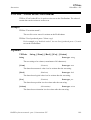
6DYH6DYHDSURJUDPPRGXOH 6HDUFK&6HDUFKHVFLUFXODUO\XVLQJWKHURERW 6HDUFK/6HDUFKHVOLQHDUO\XVLQJWKHURERW 6HW6HWVDGLJLWDORXWSXWVLJQDO 6HW$OO'DWD9DO6HWDYDOXHWRDOOGDWDREMHFWVLQDGHILQHGVHW 6HW$2&KDQJHVWKHYDOXHRIDQDQDORJRXWSXWVLJQDO 6HW'DWD6HDUFK'HILQHWKHV\PEROVHWLQDVHDUFKVHTXHQFH 6HW'DWD9DO6HWWKHYDOXHRIDGDWDREMHFW 6HW'2&KDQJHVWKHYDOXHRIDGLJLWDORXWSXWVLJQDO 6HW*2&KDQJHVWKHYDOXHRIDJURXSRIGLJLWDORXWSXWVLJQDOV 6HW6\V'DWD6HWV\VWHPGDWD 6LQJ$UHD'HILQHVLQWHUSRODWLRQDURXQGVLQJXODUSRLQWV 6NLS:DUQ6NLSWKHODWHVWZDUQLQJ 6RFNHW$FFHSW$FFHSWDQLQFRPLQJFRQQHFWLRQ 6RFNHW%LQG%LQGDVRFNHWWRDSRUWQXPEHU 6RFNHW&ORVH&ORVHDVRFNHW 6RFNHW&RQQHFW&RQQHFWWRDUHPRWHFRPSXWHU 6RFNHW&UHDWH&UHDWHDQHZVRFNHW 6RFNHW/LVWHQ/LVWHQIRULQFRPLQJFRQQHFWLRQV 6RFNHW5HFHLYH5HFHLYHGDWDIURPUHPRWHFRPSXWHU 6RFNHW6HQG6HQGGDWDWRUHPRWHFRPSXWHU 6RIW$FW$FWLYDWLQJWKHVRIWVHUYR 6RIW'HDFW'HDFWLYDWLQJWKHVRIWVHUYR 6SF&RQ&RQQHFWVWRDVWDWLVWLFDOSURFHVVFRQWUROOHU 6SF'LVFRQ'LVFRQQHFWVIURPDVWDWLVWLFDOSURFHVVFRQWUROOHU 6SF'XPS'XPSVWDWLVWLFDOSURFHVVFRQWUROLQIRUPDWLRQ 6SF5HDG5HDGVWKHFXUUHQWSURFHVVVWDWXV 6SF:ULWH:ULWHVWRDVWDWLVWLFDOSURFHVVFRQWUROOHU 6S\6WDUW6WDUWUHFRUGLQJRIH[HFXWLRQWLPHGDWD 6S\6WRS6WRSUHFRUGLQJRIWLPHH[HFXWLRQGDWD 6WDUW/RDG/RDGDSURJUDPPRGXOHGXULQJH[HFXWLRQ 6WDUW0RYH5HVWDUWVURERWPRYHPHQW 6WDUW0RYH5HWU\5HVWDUWVURERWPRYHPHQWDQG5(75<H[HFXWLRQ 67&DOLE&DOLEUDWHD6HUYR7RRO 67&ORVH&ORVHD6HUYR7RRO 6WHS%ZG3DWK0RYHEDFNZDUGVRQHVWHSRQSDWK 67,QG*XQ6HWVWKHJXQLQLQGHSHQGHQWPRGH 67,QG*XQ5HVHW5HVHWVWKHJXQIURPLQGHSHQGHQWPRGH 5$3,'UHIHUHQFHPDQXDOSDUWE,QVWUXFWLRQV6=
I
&RQWHQWV
67RRO5RW&DOLE&DOLEUDWLRQRI7&3DQGURWDWLRQIRUVWDWLRQDU\WRRO 67RRO7&3&DOLE&DOLEUDWLRQRI7&3IRUVWDWLRQDU\WRRO 6WRS6WRSVSURJUDPH[HFXWLRQ 672SHQ2SHQD6HUYR7RRO 6WRS0RYH6WRSVURERWPRYHPHQW 6WRS0RYH5HVHW5HVHWWKHV\VWHPVWRSPRYHIODJ 6WRUH3DWK6WRUHVWKHSDWKZKHQDQLQWHUUXSWRFFXUV 677XQH7XQLQJ6HUYR7RRO 677XQH5HVHW5HVHWWLQJ6HUYRWRROWXQLQJ 6\QF0RYH2II(QGFRRUGLQDWHGV\QFKURQL]HGPRYHPHQWV 6\QF0RYH2Q6WDUWFRRUGLQDWHGV\QFKURQL]HGPRYHPHQWV 6\QF0RYH8QGR6HWLQGHSHQGHQWPRYHPHQWV 6\QF7R6HQVRU6\QFWRVHQVRU 7(67'HSHQGLQJRQWKHYDOXHRIDQH[SUHVVLRQ 7HVW6LJQ'HILQH'HILQHWHVWVLJQDO 7HVW6LJQ5HVHW5HVHWDOOWHVWVLJQDOGHILQLWLRQV 7H[W7DE,QVWDOO,QVWDOOLQJDWH[WWDEOH 73(UDVH(UDVHVWH[WSULQWHGRQWKH)OH[3HQGDQW 735HDG).5HDGVIXQFWLRQNH\V 735HDG1XP5HDGVDQXPEHUIURPWKH)OH[3HQGDQW 736KRZ6ZLWFKZLQGRZRQWKH)OH[3HQGDQW 73:ULWH:ULWHVRQWKH)OH[3HQGDQW 7ULJJ&&LUFXODUURERWPRYHPHQWZLWKHYHQWV 7ULJJ&KHFN,2'HILQHV,2FKHFNDWDIL[HGSRVLWLRQ 7ULJJ(TXLS'HILQHVDIL[HGSRVLWLRQWLPH,2HYHQW 7ULJJ,QW'HILQHVDSRVLWLRQUHODWHGLQWHUUXSW 7ULJJ,2'HILQHVDIL[HGSRVLWLRQ,2HYHQW 7ULJJ-$[LVZLVHURERWPRYHPHQWVZLWKHYHQWV 7ULJJ//LQHDUURERWPRYHPHQWVZLWKHYHQWV 7ULJJ6SHHG'HILQHV7&3VSHHGSURSRUWLRQDODQDORJRXWSXWZLWKIL[HGSRVLWLRQWLPHVFDOH
HYHQW 7ULJJ6WRS3URF*HQHUDWHUHVWDUWGDWDIRUWULJJVLJQDOVDWVWRS 75<1(;7-XPSVRYHUDQLQVWUXFWLRQZKLFKKDVFDXVHGDQHUURU 7XQH5HVHW5HVHWWLQJVHUYRWXQLQJ 7XQH6HUYR7XQLQJVHUYRV 8,0VJ%R[8VHU0HVVDJH'LDORJ%R[W\SHEDVLF 8Q/RDG8Q/RDGDSURJUDPPRGXOHGXULQJH[HFXWLRQ 8QSDFN5DZ%\WHV8QSDFNGDWDIURPUDZE\WHVGDWD II
5$3,'UHIHUHQFHPDQXDOSDUWE,QVWUXFWLRQV6=
&RQWHQWV
9HO6HW&KDQJHVWKHSURJUDPPHGYHORFLW\ :DLW',:DLWVXQWLODGLJLWDOLQSXWVLJQDOLVVHW :DLW'2:DLWVXQWLODGLJLWDORXWSXWVLJQDOLVVHW :DLW/RDG&RQQHFWWKHORDGHGPRGXOHWRWKHWDVN :DLW6HQVRU:DLWIRUFRQQHFWLRQRQVHQVRU :DLW6\QF7DVN:DLWIRUV\QFKURQL]DWLRQSRLQWZLWKRWKHUSURJUDPWDVNV :DLW7HVW$QG6HW:DLWXQWLOYDULDEOHXQVHWWKHQVHW :DLW7LPH:DLWVDJLYHQDPRXQWRIWLPH :DLW8QWLO:DLWVXQWLODFRQGLWLRQLVPHW :DLW:2EM:DLWIRUZRUNREMHFWRQFRQYH\RU :DUP6WDUW5HVWDUWWKHFRQWUROOHU :+,/(5HSHDWVDVORQJDV :RUOG$FF/LP&RQWURODFFHOHUDWLRQLQZRUOGFRRUGLQDWHV\VWHP :ULWH:ULWHVWRDFKDUDFWHUEDVHGILOHRUVHULDOFKDQQHO :ULWH$Q\%LQ:ULWHVGDWDWRDELQDU\VHULDOFKDQQHORUILOH :ULWH%LQ:ULWHVWRDELQDU\VHULDOFKDQQHO :ULWH%ORFNZULWHEORFNRIGDWDWRGHYLFH :ULWH&IJ'DWD:ULWHVDWWULEXWHRIDV\VWHPSDUDPHWHU :ULWH5DZ%\WHV:ULWHUDZE\WHVGDWD :ULWH6WU%LQ:ULWHVDVWULQJWRDELQDU\VHULDOFKDQQHO :ULWH9DUZULWHYDULDEOH :=%R['HI'HILQHDER[VKDSHGZRUOG]RQH :=&\O'HI'HILQHDF\OLQGHUVKDSHGZRUOG]RQH :='LVDEOH'HDFWLYDWHWHPSRUDU\ZRUOG]RQHVXSHUYLVLRQ :='26HW$FWLYDWHZRUOG]RQHWRVHWGLJLWDORXWSXW :=(QDEOH$FWLYDWHWHPSRUDU\ZRUOG]RQHVXSHUYLVLRQ :=)UHH(UDVHWHPSRUDU\ZRUOG]RQHVXSHUYLVLRQ :=+RPH-RLQW'HI'HILQHDZRUOG]RQHIRUKRPHMRLQWV :=/LP-RLQW'HI'HILQHDZRUOG]RQHIRUOLPLWDWLRQLQMRLQWV :=/LP6XS$FWLYDWHZRUOG]RQHOLPLWVXSHUYLVLRQ :=6SK'HI'HILQHDVSKHUHVKDSHGZRUOG]RQH 5$3,'UHIHUHQFHPDQXDOSDUWE,QVWUXFWLRQV6=
III
&RQWHQWV
IV
5$3,'UHIHUHQFHPDQXDOSDUWE,QVWUXFWLRQV6=
6DYH
,QVWUXFWLRQ
5RERW:DUH26
6DYH6DYHDSURJUDPPRGXOH
6DYHis used to save a program module.
The specified program module in the program memory will be saved with the original
(specified in/RDGor 6WDUW/RDG) or specified file path.
It is also possible to save a system module at the specified file path.
([DPSOH
Load "HOME:/PART_B.MOD";
...
Save "PART_B";
Load the program module with the file name 3$57B%02' from +20( into
the program memory.
Save the program module 3$57B% with the original file path +20(and with
the original file name 3$57B%02'.
$UJXPHQWV
6DYH>?7DVN5HI@0RGXOH1DPH>?)LOH3DWK@>?)LOH@
>?7DVN5HI@
'DWDW\SHWDVNLG
The program task in which the program module should be saved.
If this argument is omitted, the specified program module in the current (executing) program task will be saved.
For all program tasks in the system, predefined variables of the data type WDVNLG
will be available. The variable identity will be "taskname"+"Id", e.g. for the
T_ROB1 task the variable identity will be T_ROB1Id, TSK1 - TSK1Id etc.
0RGXOH1DPH
'DWDW\SH VWULQJ
The program module to save.
>?)LOH3DWK@
'DWDW\SHVWULQJ
The file path and the file name to the place where the program module is to be
saved. The file name shall be excluded when the argument ?)LOH is used.
>?)LOH@
'DWDW\SHVWULQJ
When the file name is excluded in the argument \)LOH3DWKit must be specified
5$3,'UHIHUHQFHPDQXDOSDUW,QVWUXFWLRQV6=
1
6DYH
5RERW:DUH26
,QVWUXFWLRQ
with this argument.
The argument ?)LOH3DWK can only be omitted for program modules loaded with /RDGor
6WDUW/RDG:DLW/RDG and the program module will be stored at the same destination as
specified in these instructions. To store the program module at another destination it is
also possible to use the argument \)LOH3DWK.
To be able to save a program module that previously was loaded from the FlexPendant,
external computer, or system configuration, the argument ?)LOH3DWK must be used.
3URJUDPH[HFXWLRQ
Program execution waits for the program module to finish saving before proceeding
with the next instruction.
([DPSOH
Save "PART_A" \FilePath:="HOME:/DOORDIR/PART_A.MOD";
Save the program module 3$57B$ to +20( in the file 3$57B$02'and in
the directory '225',5.
Save "PART_A" \FilePath:="HOME:” \File:=”DOORDIR/PART_A.MOD";
Same as above but another syntax.
Save \TaskRef:=TSK1Id, "PART_A" \FilePath:="HOME:/DOORDIR/
PART_A.MOD";
Save program module 3$57B$ in program task 76. to the specified destination.
This is an example where the instruction 6DYHis executing in one program task
and the saving is done in another program task.
/LPLWDWLRQV
TRAP routines, system I/O events and other program tasks cannot execute during the
saving operation. Therefore, any such operations will be delayed.
The save operation can interrupt update of PERS data done step by step from other program tasks. This will result in inconsistent whole PERS data.
2
5$3,'UHIHUHQFHPDQXDOSDUW,QVWUXFWLRQV6=
6DYH
,QVWUXFWLRQ
5RERW:DUH26
A program stop during execution of the 6DYHinstruction can result in a guard stop with
motors off and the error message "20025 Stop order timeout" will be displayed on the
FlexPendant.
Avoid ongoing robot movements during the saving.
(UURUKDQGOLQJ
If the program module cannot be saved because there is no module name, unknown, or
ambiguous module name, the system variable ERRNO is set to ERR_MODULE.
If the save file cannot be opened because of permission denied, no such directory, or
no space left on device, the system variable ERRNO is set to ERR_IOERROR.
If argument ?)LOH3DWK is not specified for program modules loaded from the FlexPendant, System Parameters, or an external computer, the system variable ERRNO is set
to ERR_PATH.
The errors above can be handled in the error handler.
6\QWD[
Save
[ ’\’ TaskRef ’:=’ <variable (9$5) of WDVNLG> ’,’ ]
[ ModuleName ’:=’ ] <expression (,1) of VWULQJ>
[ ’\’ FilePath ’:=’<expression (,1) of VWULQJ> ]
[ ’\’ File ’:=’ <expression (,1) of VWULQJ>] ’;’
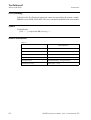
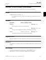
5HODWHGLQIRUPDWLRQ
7DEOH
Described in:
Program tasks
5$3,'UHIHUHQFHPDQXDOSDUW,QVWUXFWLRQV6=
Data Types - WDVNLG
3
6DYH
5RERW:DUH26
4
,QVWUXFWLRQ
5$3,'UHIHUHQFHPDQXDOSDUW,QVWUXFWLRQV6=
6&:ULWH
,QVWUXFWLRQ
3&LQWHUIDFHEDFNXS
6&:ULWH6HQGYDULDEOHGDWDWRDFOLHQWDSSOLFDWLRQ
6&:ULWH 6XSHULRU&RPSXWHU:ULWH is used to send the name, type, dimension and
value of a persistent variable to a client application. It is possible to send both single
variables and arrays of variables.
([DPSOHV
PERS num cycle_done;
PERS num numarr{2}:=[1,2];
SCWrite cycle_done;
The name, type and value of the persistent variable F\FOHBGRQH is sent to all client
applications.
SCWrite \ToNode := "138.221.228.4", cycle_done;
The name, type and value of the persistent variable F\FOHBGRQH is sent to all client
applications. The argument ToNode will be ignored.
SCWrite numarr;
The name, type, dim and value of the persistent variable QXPDUU is sent to all client applications.
SCWrite \ToNode := "138.221.228.4", numarr;
The name, type, dim and value of the persistent variable QXPDUU is sent to all client applications. The argument ToNode will be ignored.
$UJXPHQWV
6&:ULWH>?7R1RGH@9DULDEOH
>?7R1RGH@
'DWDW\SHVWULQJ
The node name does not have any effect, the node name can still be used.
9DULDEOH
'DWDW\SHDQ\W\SH
The name of a persistent variable.
5$3,'UHIHUHQFHPDQXDOSDUW,QVWUXFWLRQV6=
5
6&:ULWH
3&LQWHUIDFHEDFNXS
,QVWUXFWLRQ
3URJUDPH[HFXWLRQ
The name, type, dim and value of the persistent variable is sent to all client applications.
‘dim’ is the dimension of the variable and is only sent if the variable is an array.
6\QWD[
SCWrite
[ ’\’ ToNode ’:=’ < expression (,1) of VWULQJ> ’,’]
[ Variable’:=’ ] < persistent (3(56) of DQ\W\SH>’;’
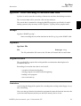
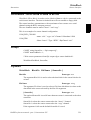
(UURUKDQGOLQJ
The SCWrite instruction will return an error in the following cases:
- The variable could not be sent to the client. This can have the following cause:
-
The SCWrite messages comes so close so that they cannot be sent to the client.
Solution: Put in a :DLW7LPH instruction between the 6&:ULWH instructions.
-
The variable value is to large, decrease the size of the ARRAY or RECORD
-
The error message will be:
41473 System access error
Failed to send YYYYYY
Where YYYY is the name of the variable.
When an error occurs the program halts and must be restarted. The (5512 system
variable will contain the value (55B6&B:5,7(.
The SCWrite instruction will not return an error if the client application may for example be closed down or the communication is down. The program will continue executing.
6&:ULWHHUURUUHFRYHU\
To avoid stopping the program when a error occurs in a SCWrite instruction it have to
be handled by anHUURUKDQGOHUThe error will then only be reported to the log and the
program will continue running.
Remember that the error handling will make it more difficult to find errors in the client
communication since the error is never reported to the display on the FlexPendant (but
it can be found in the log).
6
5$3,'UHIHUHQFHPDQXDOSDUW,QVWUXFWLRQV6=
6&:ULWH
,QVWUXFWLRQ
3&LQWHUIDFHEDFNXS
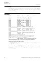
8VLQJ5RERW:DUHRUODWHU
The RAPID program looks as follows:.
MODULE SCW
PROC main()
.
.
.
Execution starts here
1
SCWrite load0;
.
.
.
3
2
If an error occurs
ERROR
IF ERRNO=ERR_SC_WRITE THEN
! Place the error code for handling the SCWrite Error here (If you want any)
TRYNEXT;
ELSE
! Place the error code for handling all other errors here
ENDIF
ENDPROC
ENDMODULE
5$3,'UHIHUHQFHPDQXDOSDUW,QVWUXFWLRQV6=
7
6&:ULWH
3&LQWHUIDFHEDFNXS
8
,QVWUXFWLRQ
5$3,'UHIHUHQFHPDQXDOSDUW,QVWUXFWLRQV6=
6HDUFK&
,QVWUXFWLRQ
5RERW:DUH26
6HDUFK&6HDUFKHVFLUFXODUO\XVLQJWKHURERW
6HDUFK& 6HDUFK&LUFXODU is used to search for a position when moving the tool centre
point (TCP) circularly.
During the movement, the robot supervises a digital input signal. When the value of
the signal changes to the requested one, the robot immediately reads the current position.
This instruction can typically be used when the tool held by the robot is a probe for
surface detection. Using the 6HDUFK& instruction, the outline coordinates of a work
object can be obtained.
This instruction can only be used in the 0DLQ task or, if in a MultiMove System, in
Motion tasks.
When using search instructions, it is important to configure the I/O system to have very
short time from setting the physical signal to the system get the information about the
setting (use I/O unit with interrupt control, not poll control). How to do this can differ
between fieldbuses. If using DeviceNet, the ABB units DSQC 327A (AD Combi I/O)
and DSQC 328A (Digital IO) will give short times, since they are using connection
type Change of State. If using other fieldbuses make sure to configure the network in
a proper way to get right conditions.
([DPSOHV
SearchC di1, sp, cirpoint, p10, v100, probe;
The TCP of the SUREH is moved circularly towards the position Sat a speed of
Y. When the value of the signal GLchanges to active, the position is stored
in VS.
SearchC \Stop, di2, sp, cirpoint, p10, v100, probe;
The TCP of the SUREH is moved circularly towards the position S. When the
value of the signal GLchanges to active, the position is stored in VS and the robot
stops immediately.
$UJXPHQWV
6HDUFK&>?6WRS@_>?36WRS@_>?66WRS@_>?6XS@6LJQDO>?)ODQNV@
6HDUFK3RLQW&LU3RLQW7R3RLQW>?,'@6SHHG>?9@_>?7@
7RRO>?:2EM@>?&RUU@
>?6WRS@
6WLII6WRS
'DWDW\SHVZLWFK
The robot movement is stopped, as quickly as possible, without keeping the TCP
on the path (hard stop), when the value of the search signal changes to active.
5$3,'UHIHUHQFHPDQXDOSDUW,QVWUXFWLRQV6=
9
6HDUFK&
5RERW:DUH26
,QVWUXFWLRQ
However, the robot is moved a small distance before it stops and is not moved
back to the searched position, i.e. to the position where the signal changed.
To stop the searching with stiff stop (switch \Stop) is only allowed if the TCPspeed is lower than 100 mm/s. At stiff stop with higher speed, some axes can
move in unpredictable direction.
>?36WRS@
3DWK6WRS
'DWDW\SHVZLWFK
The robot movement is stopped as quickly as possible, while keeping the TCP on
the path (soft stop), when the value of the search signal changes to active. However, the robot is moved a distance before it stops and is not moved back to the
searched position, i.e. to the position where the signal changed.
>?66WRS@
6RIW6WRS
'DWDW\SHVZLWFK
The robot movement is stopped as quickly as possible, while keeping the TCP
close to or on the path (soft stop), when the value of the search signal changes to
active. However, the robot is moved only a small distance before it stops and is
not moved back to the searched position, i.e. to the position where the signal
changed. 66WRS is faster then 36WRS. But when the robot is running faster than 100
mm/s, it stops in the direction of the tangent of the movement which causes it to
marginally slide of the path.
>?6XS@
6XSHUYLVLRQ
'DWDW\SHVZLWFK
The search instruction is sensitive to signal activation during the complete movement (flying search), i.e. even after the first signal change has been reported. If
more than one match occurs during a search, program execution stops.
If the argument \6WRS, \36WRS, \66WRSRU?6XSis omitted, the movement continues
(flying search) to the position specified in the 7R3RLQW argument (same as with
argument \6XS),
6LJQDO
'DWDW\SHVLJQDOGL
The name of the signal to supervise.
>?)ODQNV@
'DWDW\SHVZLWFK
The positive and the negative edge of the signal is valid for a search hit.
If the argument ?)ODQNVis omitted, only the positive edge of the signal is valid for
a search hit and a signal supervision will be activated at the beginning of a search
process. This means that if the signal has a positive value already at the beginning
of a search process, the robot movement is stopped as quickly as possible, while
keeping the TCP on the path (soft stop). However, the robot is moved a small distance before it stops and is not moved back to the start position. A user recovery
error (ERR_SIGSUPSEARCH) will be generated and can be dealt with by the
error handler.
10
5$3,'UHIHUHQFHPDQXDOSDUW,QVWUXFWLRQV6=
6HDUFK&
,QVWUXFWLRQ
5RERW:DUH26
6HDUFK3RLQW
'DWDW\SHUREWDUJHW
The position of the TCP and external axes when the search signal has been triggered. The position is specified in the outermost coordinate system, taking the
specified tool, work object and activeProgDisp/ExtOffs coordinate system into
consideration.
&LU3RLQW
'DWDW\SHUREWDUJHW
The circle point of the robot. See the instruction MoveC for a more detailed
description of circular movement. The circle point is defined as a named position
or stored directly in the instruction (marked with an * in the instruction).
7R3RLQW
'DWDW\SHUREWDUJHW
The destination point of the robot and external axes. It is defined as a named
position or stored directly in the instruction (marked with an * in the instruction).
6HDUFK& always uses a stop point as zone data for the destination.
>?,'@
6\QFKURQL]DWLRQLG
'DWDW\SHLGHQWQR
This argument must be used in a MultiMove System, if coordinated synchronized movement, and is not allowed in any other cases.
The specified id number must be the same in all cooperating program tasks. The
id number gives a guarantee that the movements are not mixed up at runtime.
6SHHG
'DWDW\SHVSHHGGDWD
The speed data that applies to movements. Speed data defines the velocity of the
tool centre point, the external axes and of the tool reorientation.
>?9@
9HORFLW\
'DWDW\SHQXP
This argument is used to specify the velocity of the TCP in mm/s directly in the
instruction. It is then substituted for the corresponding velocity specified in the
speed data.
>?7@
7LPH
'DWDW\SHQXP
This argument is used to specify the total time in seconds during which the robot
moves. It is then substituted for the corresponding speed data.
7RRO
'DWDW\SHWRROGDWD
The tool in use when the robot moves. The tool centre point is the point that is
moved to the specified destination position.
>?:2EM@
:RUN2EMHFW
'DWDW\SHZREMGDWD
The work object (coordinate system) to which the robot positions in the instruction are related.
This argument can be omitted, and if it is, the position is related to the world
5$3,'UHIHUHQFHPDQXDOSDUW,QVWUXFWLRQV6=
11
6HDUFK&
5RERW:DUH26
,QVWUXFWLRQ
coordinate system. If, on the other hand, a stationary TCP or coordinated external
axes are used, this argument must be specified for a linear movement relative to
the work object to be performed.
>?&RUU@
&RUUHFWLRQ
'DWDW\SHVZLWFK
Correction data written to a corrections entry by the instruction &RUU:ULWH will be
added to the path and destination position, when this argument is present.
3URJUDPH[HFXWLRQ
See the instruction 0RYH& for information about circular movement.
The movement is always ended with a stop point, i.e. the robot is stopped at the destination point.
When a flying search is used, i.e. the ?6XS argument is specified, the robot movement
always continues to the programmed destination point. When a search is made using
the switch \6WRS, ?36WRS or \66WRS, the robot movement stops when the first signal is
detected.
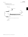
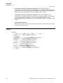
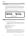
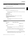
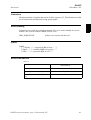
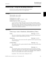
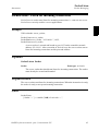
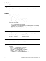
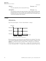
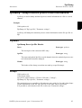
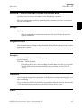
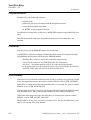
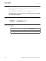
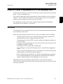
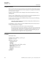
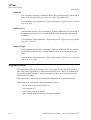
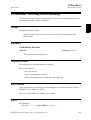
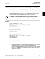
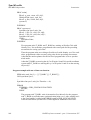
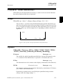
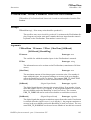
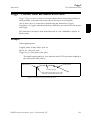
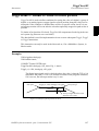
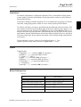
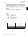
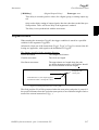
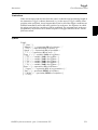
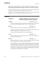
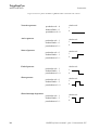
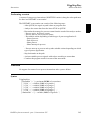
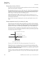
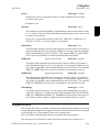
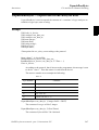
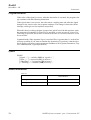
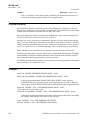
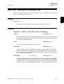
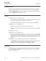
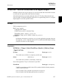
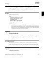
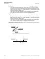
The 6HDUFK& instruction returns the position of the TCP when the value of the digital
signal changes to the requested one, as illustrated in Figure 1.
Without switch \Flanks
1
0
With switch \Flanks
time
1
0
time
= Instruction reaction when
the signal changes
)LJXUH)ODQNWULJJHUHGVLJQDOGHWHFWLRQ WKHSRVLWLRQLVVWRUHGZKHQWKHVLJQDOLV
FKDQJHGWKHILUVWWLPHRQO\ ([DPSOH
SearchC \Sup, di1\Flanks, sp, cirpoint, p10, v100, probe;
The TCP of the SUREH is moved circularly towards the position S. When the
value of the signal GLchanges to active or passive, the position is stored in VS. If
the value of the signal changes twice, program execution stops.
12
5$3,'UHIHUHQFHPDQXDOSDUW,QVWUXFWLRQV6=
6HDUFK&
,QVWUXFWLRQ
5RERW:DUH26
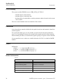
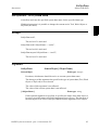
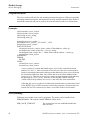
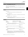
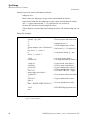
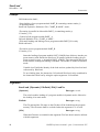
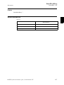
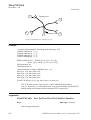
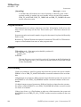
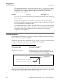
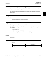
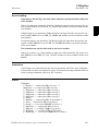
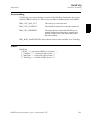
/LPLWDWLRQV
General limitations according to instruction MoveC.
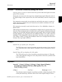
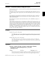
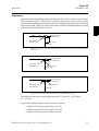
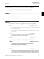
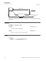
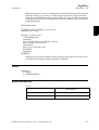
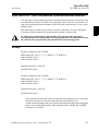
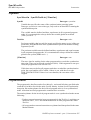
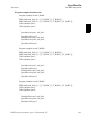
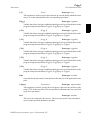
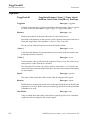
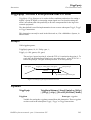
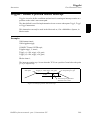
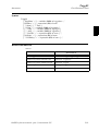
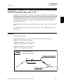
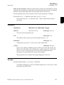
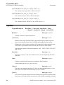
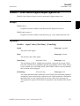
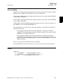
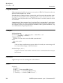
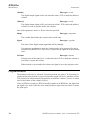
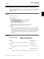
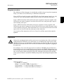
Zone data for the positioning instruction that precedes 6HDUFK& must be used carefully.
The start of the search, i.e. when the I/O signal is ready to react, is not, in this case, the
programmed destination point of the previous positioning instruction, but a point along
the real robot path. Figure 2 illustrates an example of something that may go wrong
when zone data other than ILQH is used.
The instruction 6HDUFK& should never be restarted after the circle point has been
passed. Otherwise the robot will not take the programmed path (positioning around the
circular path in another direction compared with that programmed).
Start point with
zone data]
Search object
End point
Start point with
zone dataILQH
)LJXUH$PDWFKLVPDGHRQWKHZURQJVLGHRIWKHREMHFWEHFDXVHWKHZURQJ]RQHGDWD
ZDVXVHG
Repetition accuracy for search hit position with TCP speed 20 - 1000 mm/s
0.1 - 0.3 mm.
Typical stop distance using a search velocity of 50 mm/s:
- without TCP on path (switch \6WRS) 1-3 mm
- with TCP on path (switch \36WRS) 15-25 mm
- with TCP near path (switch \66WRS) 4-8 mm
(UURUKDQGOLQJ
An error is reported during a search when:
- no signal detection occurred - this generates the error ERR_WHLSEARCH.
- more than one signal detection occurred – this generates the error
ERR_WHLSEARCH only if the ?6XSargument is used.
- the signal has already a positive value at the beginning of the search process this generates the error ERR_SIGSUPSEARCH only if the ?)ODQNV argument
is omitted.
Errors can be handled in different ways depending on the selected running mode:
5$3,'UHIHUHQFHPDQXDOSDUW,QVWUXFWLRQV6=
13
6HDUFK&
5RERW:DUH26
,QVWUXFWLRQ
&RQWLQXRXVIRUZDUG / ,QVWUXFWLRQ IRUZDUGERR_WHLSEARCH
No position is returned and the movement always continues to the programmed
destination point. The system variable ERRNO is set to ERR_WHLSEARCH
and the error can be handled in the error handler of the routine.
&RQWLQXRXVIRUZDUG/,QVWUXFWLRQ IRUZDUG/ ERR_SIGSUPSEARCH
No position is returned and the movement always stops as quickly as possible at
the beginning of the search path. The system variable ERRNO is set to
ERR_SIGSUPSEARCH and the error can be handled in the error handler of the
routine.
,QVWUXFWLRQ EDFNZDUG
During backward execution, the instruction just carries out the movement without any signal supervision.
6\QWD[
SearchC [ ’\’ Stop’,’ ] | [ ’\’ PStop ’,’] | [ ’\’ SStop ’,’ ] | [ ’\’ Sup ’,’ ]
[ Signal ’:=’ ] < variable (9$5) of VLJQDOGL >
[‘\’ Flanks]’,’
[ SearchPoint ’:=’ ] < var or pers (,1287) of UREWDUJHW > ’,’
[ CirPoint ’:=’ ] < expression (,1) of UREWDUJHW > ’,’
[ ToPoint ’:=’ ] < expression (,1) of UREWDUJHW > ’,’
[ ’\’ ID ’:=’ < expression (,1) of LGHQWQR >]’,’
[ Speed ’:=’ ] < expression (,1) of VSHHGGDWD >
[ ’\’ V ’:=’ < expression (,1) of QXP > ] [ ’\’ T ’:=’ < expression (,1) of QXP > ] ’,’
[ Tool ’:=’ ] < persistent (3(56) of WRROGDWD > [’\’ WObj ’:=’ < persistent (3(56) of ZREMGDWD > ] [ ’\’ Corr ]’;’
14
5$3,'UHIHUHQFHPDQXDOSDUW,QVWUXFWLRQV6=
6HDUFK&
,QVWUXFWLRQ
5RERW:DUH26
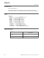
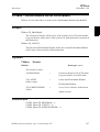
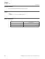
5HODWHGLQIRUPDWLRQ
7DEOH
Described in:
Linear searches
Instructions - 6HDUFK/
Writes to a corrections entry
Instructions - &RUU:ULWH
Circular movement
Motion and I/O Principles - 3RVLWLRQLQJGXULQJ
3URJUDP([HFXWLRQ
Definition of velocity
Data Types - VSHHGGDWD
Definition of tools
Data Types - WRROGDWD
Definition of work objects
Data Types - ZREMGDWD
Using error handlers
RAPID Summary - (UURU5HFRYHU\
Motion in general
Motion and I/O Principles
More searching examples
Instructions - 6HDUFK/
5$3,'UHIHUHQFHPDQXDOSDUW,QVWUXFWLRQV6=
15
6HDUFK&
5RERW:DUH26
16
,QVWUXFWLRQ
5$3,'UHIHUHQFHPDQXDOSDUW,QVWUXFWLRQV6=
6HDUFK/
,QVWUXFWLRQ
5RERW:DUH26
6HDUFK/6HDUFKHVOLQHDUO\XVLQJWKHURERW
6HDUFK/ 6HDUFK/LQHDU LV used to search for a position when moving the tool centre
point (TCP) linearly.
During the movement, the robot supervises a digital input signal. When the value of
the signal changes to the requested one, the robot immediately reads the current position.
This instruction can typically be used when the tool held by the robot is a probe for
surface detection. Using the 6HDUFK/ instruction, the outline coordinates of a work
object can be obtained.
This instruction can only be used in the 0DLQ task or, if in a MultiMove System, in
Motion tasks.
When using search instructions, it is important to configure the I/O system to have very
short time from setting the physical signal to the system get the information about the
setting (use I/O unit with interrupt control, not poll control). How to do this can differ
between fieldbuses. If using DeviceNet, the ABB units DSQC 327A (AD Combi I/O)
and DSQC 328A (Digital IO) will give short times, since they are using connection
type Change of State. If using other fieldbuses make sure to configure the network in
a proper way to get right conditions.
([DPSOHV
SearchL di1, sp, p10, v100, probe;
The TCP of the SUREH is moved linearly towards the position Sat a speed of
Y. When the value of the signal GLchanges to active, the position is stored
in VS.
SearchL \Stop, di2, sp, p10, v100, probe;
The TCP of the SUREH is moved linearly towards the position S. When the
value of the signal GLchanges to active, the position is stored in VS and the robot
stops immediately.
$UJXPHQWV
6HDUFK/>?6WRS@_>?36WRS@_>?66WRS@_>?6XS@6LJQDO>?)ODQNV@
6HDUFK3RLQW7R3RLQW>?,'@6SHHG>?9@_>?7@7RRO
>?:2EM@>?&RUU@
>?6WRS@
6WLII6WRS
'DWDW\SHVZLWFK
The robot movement is stopped as quickly as possible, without keeping the TCP
on the path (hard stop), when the value of the search signal changes to active.
5$3,'UHIHUHQFHPDQXDOSDUW,QVWUXFWLRQV6=
17
6HDUFK/
5RERW:DUH26
,QVWUXFWLRQ
However, the robot is moved a small distance before it stops and is not moved
back to the searched position, i.e. to the position where the signal changed.
To stop the searching with stiff stop (switch \Stop) is only allowed if the TCPspeed is lower than 100 mm/s. At stiff stop with higher speed, some axes can
move in unpredictable direction.
>?36WRS@
3DWK6WRS
'DWDW\SHVZLWFK
The robot movement is stopped as quickly as possible, while keeping the TCP on
the path (soft stop), when the value of the search signal changes to active. However, the robot is moved a distance before it stops and is not moved back to the
searched position, i.e. to the position where the signal changed.
>?66WRS@
6RIW6WRS
'DWDW\SHVZLWFK
The robot movement is stopped as quickly as possible, while keeping the TCP
close to or on the path (soft stop), when the value of the search signal changes to
active. However, the robot is moved only a small distance before it stops and is
not moved back to the searched position, i.e. to the position where the signal
changed. 66WRS is faster then 36WRS. But when the robot is running faster than 100
mm/s it stops in the direction of the tangent of the movement which causes it to
marginally slide off the path.
>?6XS@
6XSHUYLVLRQ
'DWDW\SHVZLWFK
The search instruction is sensitive to signal activation during the complete movement (flying search), i.e. even after the first signal change has been reported. If
more than one match occurs during a search, program execution stops.
If the argument \6WRS, \36WRS, \66WRS or \6XS is omitted, the movement continues
(flying search) to the position specified in the 7R3RLQW argument (same as with
argument \6XS).
6LJQDO
'DWDW\SHVLJQDOGL
The name of the signal to supervise.
>?)ODQNV@
'DWDW\SHVZLWFK
The positive and the negative edge of the signal is valid for a search hit.
If the argument ?)ODQNVis omitted, only the positive edge of the signal is valid for
a search hit and a signal supervision will be activated at the beginning of a search
process. This means that if the signal has the positive value already at the beginning of a search process, the robot movement is stopped as quickly as possible,
while keeping the TCP on the path (soft stop). A user recovery error
(ERR_SIGSUPSEARCH) will be generated and can be handled in the error handler.
6HDUFK3RLQW
'DWDW\SHUREWDUJHW
The position of the TCP and external axes when the search signal has been trig-
18
5$3,'UHIHUHQFHPDQXDOSDUW,QVWUXFWLRQV6=
6HDUFK/
,QVWUXFWLRQ
5RERW:DUH26
gered. The position is specified in the outermost coordinate system, taking the
specified tool, work object and active ProgDisp/ExtOffs coordinate system into
consideration.
7R3RLQW
'DWDW\SHUREWDUJHW
The destination point of the robot and external axes. It is defined as a named
position or stored directly in the instruction (marked with an * in the instruction).
6HDUFK/ always uses a stop point as zone data for the destination.
>?,'@
6\QFKURQL]DWLRQLG
'DWDW\SHLGHQWQR
This argument must be used in a MultiMove System, if coordinated synchronized movement, and is not allowed in any other cases.
The specified id number must be the same in all cooperating program tasks. The
id number gives a guarantee that the movements are not mixed up at runtime.
6SHHG
'DWDW\SHVSHHGGDWD
The speed data that applies to movements. Speed data defines the velocity of the
tool centre point, the external axes and of the tool reorientation.
>?9@
9HORFLW\
'DWDW\SHQXP
This argument is used to specify the velocity of the TCP in mm/s directly in the
instruction. It is then substituted for the corresponding velocity specified in the
speed data.
>?7@
7LPH
'DWDW\SHQXP
This argument is used to specify the total time in seconds during which the robot
moves. It is then substituted for the corresponding speed data.
7RRO
'DWDW\SHWRROGDWD
The tool in use when the robot moves. The tool centre point is the point that is
moved to the specified destination position.
>?:2EM@
:RUN2EMHFW
'DWDW\SHZREMGDWD
The work object (coordinate system) to which the robot position in the instruction is related.
This argument can be omitted, and if it is, the position is related to the world
coordinate system. If, on the other hand, a stationary TCP or coordinated external axes are used, this argument must be specified for a linear movement relative
to the work object to be performed.
>?&RUU@
&RUUHFWLRQ
'DWDW\SHVZLWFK
Correction data written to a corrections entry by the instruction &RUU:ULWH will
be added to the path and destination position, if this argument is present.
5$3,'UHIHUHQFHPDQXDOSDUW,QVWUXFWLRQV6=
19
6HDUFK/
5RERW:DUH26
,QVWUXFWLRQ
3URJUDPH[HFXWLRQ
See the instruction 0RYH/ for information about linear movement.
The movement always ends with a stop point, i.e. the robot stops at the destination
point.If a flying search is used, i.e. the ?6XS argument is specified, the robot movement
always continues to the programmed destination point. If a search is made using the
switch \6WRS, \36WRS RU?66WRS, the robot movement stops when the first signal is
detected.
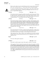
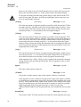
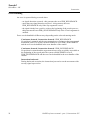
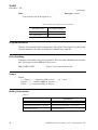
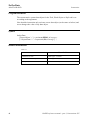
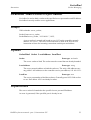
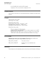
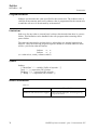
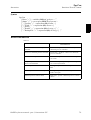
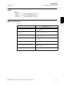
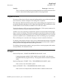
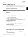
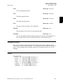
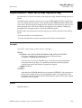
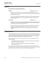
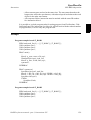
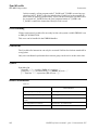
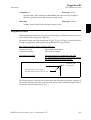
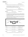
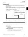
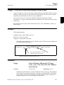
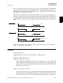
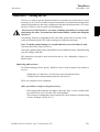
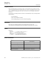
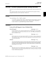
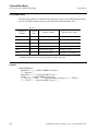
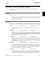
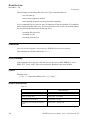
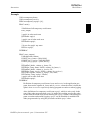
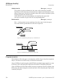
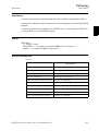
The 6HDUFK/ instruction stores the position of the TCP when the value of the digital signal changes to the requested one, as illustrated in Figure 3.
Without switch \Flanks
1
0
With switch \Flanks
time
1
0
time
= Instruction reaction when
the signal changes
)LJXUH)ODQNWULJJHUHGVLJQDOGHWHFWLRQ WKHSRVLWLRQLVVWRUHGZKHQWKHVLJQDOLV
FKDQJHGWKHILUVWWLPHRQO\ ([DPSOHV
SearchL \Sup, di1\Flanks, sp, p10, v100, probe;
The TCP of the SUREH is moved linearly towards the position S. When the value
of the signal GLchanges to active or passive, the position is stored in VS. If the
value of the signal changes twice, program execution stops after the search process is finished.
SearchL \Stop, di1, sp, p10, v100, tool1;
MoveL sp, v100, fine \Inpos := inpos50, tool1;
PDispOn *, tool1;
MoveL p100, v100, z10, tool1;
MoveL p110, v100, z10, tool1;
MoveL p120, v100, z10, tool1;
PDispOff;
At the beginning of the search process, a check on the signal GLwill be doneand
if the signal already has a positive value, the program execution stops.
Otherwise the TCP of WRROis moved linearly towards the position S. When the
value of the signal GLchanges to active, the position is stored in VS The robot is
moved back to this point using an accurately defined stop point. Using program
displacement, the robot then moves relative to the searched position, VS.
20
5$3,'UHIHUHQFHPDQXDOSDUW,QVWUXFWLRQV6=
6HDUFK/
,QVWUXFWLRQ
5RERW:DUH26
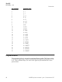
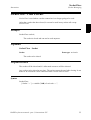
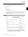
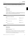
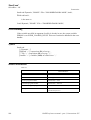
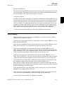
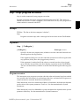
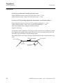
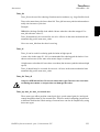
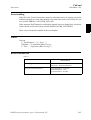
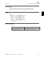
/LPLWDWLRQV
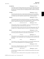
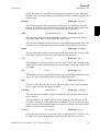
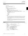
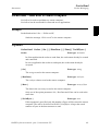
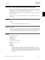
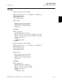
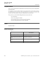
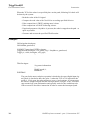
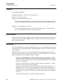
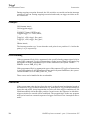
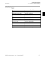
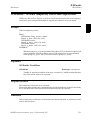
Zone data for the positioning instruction that precedes 6HDUFK/ must be used carefully.
The start of the search, i.e. when the I/O signal is ready to react, is not, in this case, the
programmed destination point of the previous positioning instruction, but a point along
the real robot path. Figure 4 to Figure 6 illustrate examples of things that may go wrong
when zone data other than ILQH is used.
Start point with
zone dataILQH
Start point with
zone data]
Search object
End point
)LJXUH$PDWFKLVPDGHRQWKHZURQJVLGHRIWKHREMHFWEHFDXVHWKHZURQJ]RQHGDWD
ZDVXVHG
Start point with
zone dataILQH
Start point with
zone data]
Search object
End point
)LJXUH1RPDWFKGHWHFWHGEHFDXVHWKHZURQJ]RQHGDWDZDVXVHG
Start point with
zone data ILQH
Start point with
zone data]
Search object
End point
)LJXUH1RPDWFKGHWHFWHGEHFDXVHWKHZURQJ]RQHGDWDZDVXVHG
Repetition accuracy for search hit position with TCP speed 20 - 1000 mm/s
0.1 - 0.3 mm.
Typical stop distance using a search velocity of 50 mm/s:
- without TCP on path (switch \6WRS) 1-3 mm
- with TCP on path (switch \36WRS) 15-25 mm
- with TCP near path (switch \66WRS) 4-8 mm
5$3,'UHIHUHQFHPDQXDOSDUW,QVWUXFWLRQV6=
21
6HDUFK/
5RERW:DUH26
,QVWUXFWLRQ
(UURUKDQGOLQJ
An error is reported during a search when:
- no signal detection occurred - this generates the error ERR_WHLSEARCH.
- more than one signal detection occurred – this generates the error
ERR_WHLSEARCH only if the ?6XSargument is used.
- the signal already has a positive value at the beginning of the search process this generates the error ERR_SIGSUPSEARCH only if the ?)ODQNV argument is
omitted.
Errors can be handled in different ways depending on the selected running mode:
&RQWLQXRXVIRUZDUG / ,QVWUXFWLRQ IRUZDUG/ ERR_WHLSEARCH
No position is returned and the movement always continues to the programmed
destination point. The system variable ERRNO is set to ERR_WHLSEARCH
and the error can be handled in the error handler of the routine.
&RQWLQXRXVIRUZDUG,QVWUXFWLRQ IRUZDUG/ ERR_SIGSUPSEARCH
No position is returned and the movement always stops as quickly as possible at
the beginning of the search path.The system variable ERRNO is set to
ERR_SIGSUPSEARCH and the error can be handled in the error handler of the
routine.
,QVWUXFWLRQ EDFNZDUG
During backward execution, the instruction just carries out the movement without any signal supervision.
22
5$3,'UHIHUHQFHPDQXDOSDUW,QVWUXFWLRQV6=
6HDUFK/
,QVWUXFWLRQ
5RERW:DUH26
([DPSOH
VAR num fk;
.
MoveL p10, v100, fine, tool1;
SearchL \Stop, di1, sp, p20, v100, tool1;
.
ERROR
IF ERRNO=ERR_WHLSEARCH THEN
MoveL p10, v100, fine, tool1;
RETRY;
ELSEIF ERRNO=ERR_SIGSUPSEARCH THEN
TPWrite “The signal of the SearchL instruction is already high!”;
TPReadFK fk,”Try again after manual reset of signal ?”,”YES”,””,””,””,”NO”;
IF fk = 1 THEN
MoveL p10, v100, fine, tool1;
RETRY;
ELSE
Stop;
ENDIF
ENDIF
If the signal is already active at the beginning of the search process, a user dialog
will be activated (TPReadFK ...;). Reset the signal and push YES on the user dialog and the robot moves back to p10 and tries once more. Otherwise program
execution will stop.
If the signal is passive at the beginning of the search process, the robot searches
from position S to S. If no signal detection occurs, the robot moves back to
S and tries once more.
6\QWD[
SearchL [ ’\’ Stop ’,’ ] | [ ’\’ PStop ’,’] | [ ’\’ SStop ’,’] | [ ’\’ Sup ’,’ ]
[ Signal ’:=’ ] < variable (9$5) of VLJQDOGL > [‘\’ Flanks] ’,’
[ SearchPoint ’:=’ ] < var or pers (,1287) of UREWDUJHW > ’,’
[ ToPoint ’:=’ ] < expression (,1) of UREWDUJHW > ’,’
[ ’\’ ID ’:=’ < expression (,1) of LGHQWQR >]’,’
[ Speed ’:=’ ] < expression (,1) of VSHHGGDWD >
[ ’\’ V ’:=’ < expression (,1) of QXP > ] [ ’\’ T ’:=’ < expression (,1) of QXP > ] ’,’
[ Tool ’:=’ ] < persistent (3(56) of WRROGDWD > [’\’ WObj ’:=’ < persistent (3(56) of ZREMGDWD > ] [ ’\’ Corr ]’;’
5$3,'UHIHUHQFHPDQXDOSDUW,QVWUXFWLRQV6=
23
6HDUFK/
5RERW:DUH26
,QVWUXFWLRQ
5HODWHGLQIRUPDWLRQ
7DEOH
Described in:
24
Circular searches
Instructions - 6HDUFK&
Writes to a corrections entry
Instructions - &RUU:ULWH
Linear movement
Motion and I/O Principles - 3RVLWLRQLQJGXULQJ
3URJUDP([HFXWLRQ
Definition of velocity
Data Types - VSHHGGDWD
Definition of tools
Data Types - WRROGDWD
Definition of work objects
Data Types - ZREMGDWD
Using error handlers
RAPID Summary - (UURU5HFRYHU\
Motion in general
Motion and I/O Principles
5$3,'UHIHUHQFHPDQXDOSDUW,QVWUXFWLRQV6=
6HW
,QVWUXFWLRQ
5RERW:DUH26
6HW6HWVDGLJLWDORXWSXWVLJQDO
6HWis used to set the value of a digital output signal to one.
([DPSOHV
Set do15;
The signal GR is set to 1.
Set weldon;
The signal ZHOGRQ is set to 1.
$UJXPHQWV
6HW6LJQDO
6LJQDO
'DWDW\SH VLJQDOGR
The name of the signal to be set to one.
3URJUDPH[HFXWLRQ
There is a short delay before the signal physically gets its new value. If you do not want
the program execution to continue until the signal has got its new value, you can use
the instruction 6HW'2 with the optional parameter ?6\QF.
The true value depends on the configuration of the signal. If the signal is inverted in
the system parameters, this instruction causes the physical channel to be set to zero.
(UURUKDQGOLQJ
Following recoverable error can be generated. The error can be handled in an error
handler. The system variable ERRNO will be set to:
ERR_NORUNUNIT
if there is no contact with the unit
6\QWD[
Set [ Signal ’:=’ ] < variable (9$5) ofVLJQDOGR > ’;’
5$3,'UHIHUHQFHPDQXDOSDUW,QVWUXFWLRQV6=
25
6HW
5RERW:DUH26
,QVWUXFWLRQ
5HODWHGLQIRUPDWLRQ
7DEOH
Described in:
26
Setting a digital output signal to zero
Instructions5HVHW
Change the value of a digital output signal
Instruction - 6HW'2
Input/Output instructions
RAPID Summary - ,QSXWDQG2XWSXW6LJQDOV
Input/Output functionality in general
Motion and I/O Principles - ,23ULQFLSOHV
Configuration of I/O
System Parameters
5$3,'UHIHUHQFHPDQXDOSDUW,QVWUXFWLRQV6=
6HW$OO'DWD9DO
,QVWUXFWLRQ
$GYDQFHG5$3,'
6HW$OO'DWD9DO6HWDYDOXHWRDOOGDWDREMHFWVLQDGHILQHGVHW
6HW$OO'DWD9DO 6HW$OO'DWD9DOXH make it possible to set a new value to all data
objects of a certain type that match the given grammar.
([DPSOH
VAR mydata mydata0:=0;
...
SetAllDataVal "mydata"\TypeMod:="mytypes"\Hidden,mydata0;
This will set all data objects of data type P\GDWDin the system to the same value
as the variable P\GDWD has (in the example to ). The user defined data type
P\GDWD is defined in the module P\W\SHV.
$UJXPHQWV
6HW$OO'DWD9DO
7\SH>?7\SH0RG@>?2EMHFW@>?+LGGHQ@9DOXH
7\SH
'DWDW\SHVWULQJ
The type name of the data objects to be set.
>?7\SH0RG@
7\SH0RGXOH
'DWDW\SHVWULQJ
The module name where the data type is defined, if using user defined data types.
>?2EMHFW@
'DWDW\SHVWULQJ
The default behaviour is to set all data object of the data type above, but this
option make it possible to name one or several objects with a regular expression.
(see also 6HW'DWD6HDUFK)
>?+LGGHQ@
'DWDW\SHVZLWFK
This match also data objects that are in routines (routine data or parameters) hidden by some routine in the call chain.
9DOXH
'DWDW\SHDQ\W\SH
Variable which holds the new value to be set. The data type must be same as the
data type for the object to be set.
5$3,'UHIHUHQFHPDQXDOSDUW,QVWUXFWLRQV6=
27
6HW$OO'DWD9DO
$GYDQFHG5$3,'
,QVWUXFWLRQ
3URJUDPUXQQLQJ
The instruction will fail if the specification for 7\SH or 7\SH0RG is wrong.
If the matching data object is an array, all elements of the array will be set to the specified value.
If the matching data object is read-only data, the value will not be changed.
If the system don’t have any matching data objects the instruction will accept it and
return successfully.
/LPLWDWLRQV
For a semivalue data type, it is not possible to search for the associated value data type. E.g. if searching for GLRQXP no search hit for signals VLJQDOGL and if searching for
num no search hit for signal VLJQDOJL or VLJQDODL.
It is not possible to set a value to a variable declared as LOCAL in a built in RAPID
module.
6\QWD[
SetAllDataVal [ Type ’:=’ ] < expression (,1) of VWULQJ >
[’\’TypeMod ’:=’<expression (,1) of VWULQJ>] [’\’Object ’:=’<expression (,1) of VWULQJ>] [’\’Hidden ] ’,’
[’\’Value ’:=’] <variable (9$5) of DQ\W\SH>’;’
5HODWHGLQIRUPDWLRQ
7DEOH
Described in:
28
Define a symbol set in a search session
Instructions - 6HW'DWD6HDUFK
Get next matching symbol
Functions - *HW1H[W6\P
Get the value of a data object
Instructions - *HW'DWD9DO
Set the value of a data object
Instructions - 6HW'DWD9DO
The related data type datapos
Data Types - GDWDSRV
5$3,'UHIHUHQFHPDQXDOSDUW,QVWUXFWLRQV6=
6HW$2
,QVWUXFWLRQ
5RERW:DUH26
6HW$2&KDQJHVWKHYDOXHRIDQDQDORJRXWSXWVLJQDO
6HW$2is used to change the value of an analog output signal.
([DPSOH
SetAO ao2, 5.5;
The signal DR is set to $UJXPHQWV
6HW$26LJQDO9DOXH
6LJQDO
'DWDW\SH VLJQDODR
The name of the analog output signal to be changed.
9DOXH
'DWDW\SH QXP
The desired value of the signal.
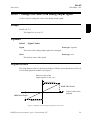
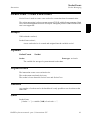
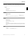
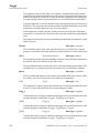
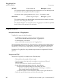
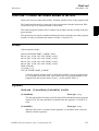
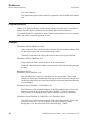
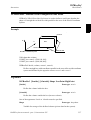
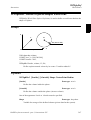
3URJUDPH[HFXWLRQ
The programmed value is scaled (in accordance with the system parameters) before it
is sent on the physical channel. See Figure 7.
Physical value of the
output signal (V, mA, etc.)
0$;SIGNAL
0$;PROGRAM
Logical value in the
program
0,1PROGRAM
0,1SIGNAL
)LJXUH'LDJUDPRIKRZDQDORJVLJQDOYDOXHVDUHVFDOHG
5$3,'UHIHUHQFHPDQXDOSDUW,QVWUXFWLRQV6=
29
6HW$2
5RERW:DUH26
,QVWUXFWLRQ
(UURUKDQGOLQJ
Following recoverable error can be generated. The error can be handled in an error handler. The system variable ERRNO will be set to:
ERR_NORUNUNIT
if there is no contact with the unit
([DPSOH
SetAO weldcurr, curr_outp;
The signal ZHOGFXUU is set to the same value as the current value of the variable
FXUUBRXWS.
6\QWD[
SetAO
[ Signal ’:=’ ] < variable (9$5) ofVLJQDODR > ’,’
[ Value ’:=’ ] < expression (,1) of QXP > ’;’
5HODWHGLQIRUPDWLRQ
7DEOH
Described in:
30
Input/Output instructions
RAPID Summary - ,QSXWDQG2XWSXW6LJQDOV
Input/Output functionality in general
Motion and I/O Principles - ,23ULQFLSOHV
Configuration of I/O
System Parameters
5$3,'UHIHUHQFHPDQXDOSDUW,QVWUXFWLRQV6=
6HW'DWD6HDUFK
,QVWUXFWLRQ
$GYDQFHG5$3,'
6HW'DWD6HDUFK'HILQHWKHV\PEROVHWLQDVHDUFKVHTXHQFH
6HW'DWD6HDUFKis used together with *HW1H[W6\P to retrieve data objects from the system.
([DPSOH
VAR datapos block;
VAR string name;
...
SetDataSearch “robtarget”\InTask;
WHILE GetNextSym(name,block \Recursive) DO
This session will find all UREWDUJHW’s object in the task.
$UJXPHQWV
6HW'DWD6HDUFK
7\SH>?7\SH0RG@>?2EMHFW@>?3HUV6\P@
>?9DU6\P@>?&RQVW6\P@>?,Q7DVN@_>?,Q0RG@
>?,Q5RXW@>?*OREDO6\P@_>?/RFDO6\P@
7\SH
'DWDW\SHVWULQJ
The data type name of the data objects to be retrieved.
>?7\SH0RG@
7\SH0RGXOH
'DWDW\SHVWULQJ
The module name where the data type is defined, if using user defined data types.
>?2EMHFW@
'DWDW\SHVWULQJ
The default behaviour is to set all data object of the data type above, but this
option makes it possible to name one or several data objects with a regular
expression.
A regular expression is a powerful mechanism to specify a grammar to match the
data object names. The string could consist of either ordinary characters and
metacharacters. A metacharacter is a special operator used to represent one or
more ordinary characters in the string, with the purpose to extend the search. It
is possible to see if a string matches a specified pattern as a whole, or search
within a string for a substring matching a specified pattern.
Within a regular expression, all alphanumeric characters match themselves, that
is to say, the pattern “abc” will only match a data object named “abc”. To match
all data object names containing the character sequence “abc”, it is necessary to
add some metacharacters. The regular expression for this is “.*abc.*”.
The available metacharacter set is shown below.
5$3,'UHIHUHQFHPDQXDOSDUW,QVWUXFWLRQV6=
31
6HW'DWD6HDUFK
$GYDQFHG5$3,'
,QVWUXFWLRQ
Expression
Meaning
Any single character.
>V@
Any single character in the non-empty set s, where s is a
sequence of characters. Ranges may be specified as c-c.
>AV@
Any singlecharacter not in the set s.
U
Zero or more occurrences of the regular expression r.
U
One or more occurrences of the regular expression r.
U"
Zero or one occurrence of the regular expression r.
U
The regular expression r. Used for separate that regular
expression from another.
U_U
The regular expressions r or r’.
Any character sequence (zero, one or several characters).
The default behaviour is to accept any symbols, but if one or several of following 3HU
V6\P, 9DU6\P or &RQVW6\P is specified, only symbols that match the specification are
accepted:
>?3HUV6\P@
3HUVLVWHQW6\PEROV
'DWDW\SHVZLWFK
Accept persistent variable (PERS) symbols.
>?9DU6\P@
9DULDEOH6\PEROV
'DWDW\SHVZLWFK
Accept variable (VAR) symbols.
>?&RQVW6\P@
&RQVWDQW6\PEROV
'DWDW\SHVZLWFK
Accept constant (CONST) symbols.
If no one of the flags\,Q7DVNor\,Q0RGare specified, the search is started at system level. The system level is the root to all other symbol definitions in the symbol tree. At the system level all built in symbols are located (built in symbols
declared LOCAL will NOT be found) plus the handle to the task level. At the task
level all loaded global symbols are located plus the handle to the modules level.
If the \5HFXUVLYH flag is set in *HW1H[W6\P the search session will enter all loaded
modules and routines below the system level.
>?,Q7DVN@
,Q7DVN
'DWDW\SHVZLWFK
Start the search at the task level. At the task level all loaded global symbols are
located plus the handle to the modules level.
If the \5HFXUVLYH flag is set in *HW1H[W6\P the search session will enter all loaded
modules and routines below the task level.
32
5$3,'UHIHUHQFHPDQXDOSDUW,QVWUXFWLRQV6=
6HW'DWD6HDUFK
,QVWUXFWLRQ
$GYDQFHG5$3,'
>?,Q0RG@
,Q0RGXOH
'DWDW\SHVWULQJ
Start the search at the specified module level. At the module level all loaded global and local symbols declared in the specified module are located plus the handle to the routines level.
If the \5HFXUVLYH flag is set in *HW1H[W6\P the search session will enter all
loaded routines below the specified module level (declared in the specified module).
>?,Q5RXW@
,Q5RXWLQH
'DWDW\SHVWULQJ
Search only at the specified routine level.
The module name for the routine must be specified in the argument \,Q0RG
The default behaviour is to match both local and global module symbols, but if
one of following \*OREDO6\P or \/RFDO6\P is specified, only symbols that match
the specification is accepted:
>?*OREDO6\P@
*OREDO6\PEROV
'DWDW\SHVZLWFK
Skip local module symbols.
Limitation: Global symbols that are built in will NOT be given.
>?/RFDO6\P@
/RFDO6\PEROV
'DWDW\SHVZLWFK
Skip global module symbols.
Limitation: Global symbols that are built in will be given, but local symbols that
are built in will NOT be given.
3URJUDPUXQQLQJ
The instruction will fail if the specification for one of 7\SH, 7\SH0RG, ,Q0RG or ,Q5RXW
is wrong.
If the system doesn’t have any matching objects the instruction will accept it and return
successfully, but the first *HW1H[W6\Pwill return FALSE.
5$3,'UHIHUHQFHPDQXDOSDUW,QVWUXFWLRQV6=
33
6HW'DWD6HDUFK
$GYDQFHG5$3,'
,QVWUXFWLRQ
/LPLWDWLRQV
Array data objects can not be defined in the symbol search set and can not be find in a
search sequence.
For a semivalue data type, it is not possible to search for the associated value data type. E.g. if searching for GLRQXP no search hit for signals VLJQDOGL and if searching for
num no search hit for signal VLJQDOJL or VLJQDODL.
Built in symbols declared as LOCAL will not be found and built in symbols declared
global will be found as local.
6\QWD[
SetDataSearch [ Type ’:=’ ] < expression (,1) of VWULQJ >
[’\’TypeMod ’:=’<expression (,1) of VWULQJ>] [’\’Object ’:=’<expression (,1) of VWULQJ>] [’\’PersSym ] [’\’VarSym ] [’\’ConstSym ] [’\’InTask ] | [’\’InMod ’:=’<expression (,1) of VWULQJ>] [’\’InRout ’:=’<expression (,1) of VWULQJ>] [’\’GlobalSym ] | [’\’LocalSym] ’;’
5HODWHGLQIRUPDWLRQ
7DEOH
Described in:
34
Get next matching symbol
Functions - *HW1H[W6\P
Get the value of a data object
Instructions - GHW'DWD9DO
Set the value of a data object
Instructions - 6HW'DWD9DO
Set the value of many data objects
Instructions - 6HW$OO'DWD9DO
The related data type datapos
Data Types - GDWDSRV
5$3,'UHIHUHQFHPDQXDOSDUW,QVWUXFWLRQV6=
6HW'DWD9DO
,QVWUXFWLRQ
$GYDQFHG5$3,'
6HW'DWD9DO6HWWKHYDOXHRIDGDWDREMHFW
6HW'DWD9DO 6HW'DWD9DOXH makes it possible to set a value for a data object that is
specified with a string variable.
([DPSOH
VAR num value:=3;
...
SetDataVal “reg”+ValToStr(ReadNum(mycom)),value;
This will set the value to a register, the number of which is received from the
serial channel P\FRP.
VAR datapos block;
VAR string name;
VAR bool truevar:=TRUE;
...
SetDataSearch “bool” \Object:=”my.*” \InMod:=”mymod”\LocalSym;
WHILE GetNextSym(name,block) DO
SetDataVal name?Block:=block,truevar;
ENDWHILE
This session will set all local ERRO that begin with P\ in the module P\PRG to TRUE.
$UJXPHQWV
6HW'DWD9DO
2EMHFW>?%ORFN@9DOXH
2EMHFW
'DWDW\SHVWULQJ
The name of the data object.
>?%ORFN@
'DWDW\SHGDWDSRV
The enclosed block to the data object. This can only be fetched with the *HW1H[W6\P function.
If this argument is omitted, the value of the visible data object in the current program execution scope will be set. No array data objects will be found.
9DOXH
'DWDW\SHDQ\W\SH
Variable which holds the new value to be set. The data type must be the same as
the data type for the data object to be set. The set value must be fetched from a
variable, but can be stored in a constant, variable or persistent.
5$3,'UHIHUHQFHPDQXDOSDUW,QVWUXFWLRQV6=
35
6HW'DWD9DO
$GYDQFHG5$3,'
,QVWUXFWLRQ
(UURUKDQGOLQJ
The system variable ERRNO is set to ERR_SYM_ACCESS if:
- the data object is non-existent
- the data object is read-only data
- the data object is routine data or routine parameter and not located in the current
active routine
The error can be handled in the error handler of the routine.
/LPLWDWLRQV
Array data objects cannot be defined in the symbol search set and cannot be found in a
search sequence.
For a semivalue data type, it is not possible to search for the associated value data type. E.g. if searching for GLRQXP, no search hit for signals VLJQDOGL will be obtained
and if searching for num, no search hit for signals VLJQDOJL or VLJQDODL will be obtained.
It is not possible to set a value to a variable declared as LOCAL in a built in RAPID
module.
6\QWD[
SetDataVal [ Object ’:=’ ] < expression (,1) of VWULQJ >
[’\’Block ’:=’<variable (9$5) of GDWDSRV>] ’,’
[ Value ’:=’ ] <variable (9$5) of DQ\W\SH>]’;’
5HODWHGLQIRUPDWLRQ
7DEOH
Described in:
36
Define a symbol set in a search session
Instructions - 6HW'DWD6HDUFK
Get next matching symbol
Functions - *HW1H[W6\P
Get the value of a data object
Instructions - *HW'DWD9DO
Set the value of many data objects
Instructions - 6HW$OO'DWD9DO
The related data type datapos
Data Types - GDWDSRV
5$3,'UHIHUHQFHPDQXDOSDUW,QVWUXFWLRQV6=
6HW'2
,QVWUXFWLRQ
5RERW:DUH26
6HW'2&KDQJHVWKHYDOXHRIDGLJLWDORXWSXWVLJQDO
6HW'2is used to change the value of a digital output signal, with or without a time
delay or synchronisation.
([DPSOHV
SetDO do15, 1;
The signal GR is set to SetDO weld, off;
The signal ZHOG is set to RII
SetDO \SDelay := 0.2, weld, high;
The signal ZHOG is set to KLJKwith a delay of s. Program execution, however,
continues with the next instruction.
SetDO \Sync ,do1, 0;
The signal GR is set to . Program execution waits until the signal is physically
set to the specified value.
$UJXPHQWV
6HW'2>?6'HOD\@_>?6\QF@6LJQDO9DOXH
>?6'HOD\@
6LJQDO'HOD\
'DWDW\SHQXP
Delays the change for the amount of time given in seconds (max. 32s).
Program execution continues directly with the next instruction. After the given
time delay, the signal is changed without the rest of the program execution being
affected.
>?6\QF@
6\QFKURQLVDWLRQ
'DWDW\SHVZLWFK
If this argument is used, the program execution will wait until the signal is physically set to the specified value.
If neither of the arguments \6'HOD\or \6\QF are used, the signal will be set as fast
as possible and the next instruction will be executed at once, without waiting for
the signal to be physically set.
6LJQDO
'DWDW\SHVLJQDOGR
The name of the signal to be changed.
5$3,'UHIHUHQFHPDQXDOSDUW,QVWUXFWLRQV6=
37
6HW'2
5RERW:DUH26
,QVWUXFWLRQ
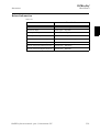
9DOXH
'DWDW\SHGLRQXP
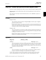
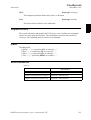
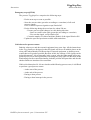
The desired value of the signal 0 or 1.
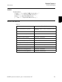
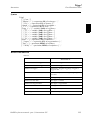
7DEOH6\VWHPLQWHUSUHWDWLRQRIVSHFLILHG9DOXH
Specified 9DOXH
Set digital output to
0
0
Any value except 0
1
3URJUDPH[HFXWLRQ
The true value depends on the configuration of the signal. If the signal is inverted in the
system parameters, the value of the physical channel is the opposite.
(UURUKDQGOLQJ
Following recoverable error can be generated. The error can be handled in an error handler. The system variable ERRNO will be set to:
ERR_NORUNUNIT
if there is no contact with the unit
6\QWD[
SetDO
[ ’\’ SDelay ’:=’ < expression (,1) of QXP > ’,’ ] |[ ’\’ Sync ’,’ ]
[ Signal ’:=’ ] < variable (9$5) ofVLJQDOGR > ’,’
[ Value ’:=’ ] < expression (,1) of GLRQXP > ’;’
5HODWHGLQIRUPDWLRQ
7DEOH
Described in:
38
Input/Output instructions
RAPID Summary - ,QSXWDQG2XWSXW6LJQDOV
Input/Output functionality in general
Motion and I/O Principles - ,23ULQFLSOHV
Configuration of I/O
6\VWHP3DUDPHWHUV
5$3,'UHIHUHQFHPDQXDOSDUW,QVWUXFWLRQV6=
6HW*2
,QVWUXFWLRQ
5RERW:DUH26
6HW*2&KDQJHVWKHYDOXHRIDJURXSRIGLJLWDORXWSXWVLJQDOV
6HW*2is used to change the value of a group of digital output signals, with or without
a time delay.
([DPSOH
SetGO go2, 12;
The signal JR is set to . IfJR comprises 4 signals, e.g. outputs 6-9, outputs
6 and 7 are set to zero, while outputs 8 and 9 are set to one.
SetGO \SDelay := 0.4, go2, 10;
The signal JR is set to . IfJR comprises 4 signals, e.g. outputs 6-9, outputs
6 and 8 are set to zero, while outputs 7 and 9 are set to one,with a delay of s.
Program execution, however, continues with the next instruction.
$UJXPHQWV
6HW*2>?6'HOD\@6LJQDO9DOXH
>?6'HOD\@
6LJQDO'HOD\
'DWDW\SHQXP
Delays the change for the period of time stated in seconds (max. 32s).
Program execution continues directly with the next instruction. After the specified time delay, the value of the signals is changed without the rest of the program execution being affected.
If the argument is omitted, the value is changed directly.
6LJQDO
'DWDW\SHVLJQDOJR
The name of the signal group to be changed.
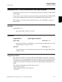
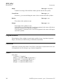
9DOXH
'DWDW\SHQXP
The desired value of the signal group (a positive integer).
The permitted value is dependent on the number of signals in the group:
5$3,'UHIHUHQFHPDQXDOSDUW,QVWUXFWLRQV6=
39
6HW*2
5RERW:DUH26
,QVWUXFWLRQ
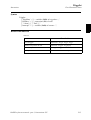
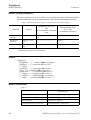
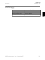
No. of signals
Permitted value
1
0-1
2
0-3
3
0-7
4
0 - 15
5
0 - 31
6
0 - 63
7
0 - 127
8
0 - 255
9
0-511
10
0-1023
11
0-2047
12
0 - 4095
13
0 - 8191
14
0 - 16383
15
0 - 32767
16
0 - 65535
17
0 - 131071
18
0 - 262143
19
0 - 524287
20
0 - 1048575
21
0 - 2097151
22
0 - 4194303
23
0 - 8388607
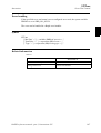
3URJUDPH[HFXWLRQ
The programmed value is converted to an unsigned binary number. This binary number
is sent on the signal group, with the result that individual signals in the group are set to
0 or 1. Due to internal delays, the value of the signal may be undefined for a short
period of time.
40
5$3,'UHIHUHQFHPDQXDOSDUW,QVWUXFWLRQV6=
6HW*2
,QVWUXFWLRQ
5RERW:DUH26
/LPLWDWLRQV
Maximum number of signals that can be used for a group is 23. This limitation is valid
for all instructions and functions using group signals.
(UURUKDQGOLQJ
Following recoverable error can be generated. The error can be handled in an error
handler. The system variable ERRNO will be set to:
ERR_NORUNUNIT
if there is no contact with the unit
6\QWD[
SetDO
[ ’\’ SDelay ’:=’ < expression (,1) of QXP > ’,’ ]
[ Signal ’:=’ ] < variable (9$5) ofVLJQDOJR > ’,’
[ Value ’:=’ ] < expression (,1) of QXP > ’;’
5HODWHGLQIRUPDWLRQ
7DEOH
Described in:
Other input/output instructions
RAPID Summary - ,QSXWDQG2XWSXW6LJQDOV
Input/Output functionality in general
Motion and I/O Principles - ,23ULQFLSOHV
Configuration of I/O (system parameters)
System Parameters
5$3,'UHIHUHQFHPDQXDOSDUW,QVWUXFWLRQV6=
41
6HW*2
5RERW:DUH26
42
,QVWUXFWLRQ
5$3,'UHIHUHQFHPDQXDOSDUW,QVWUXFWLRQV6=
6HW6\V'DWD
,QVWUXFWLRQ
$GYDQFHG5$3,'
6HW6\V'DWD6HWV\VWHPGDWD
6HW6\V'DWDactivates the specified system data name for the specified data type.
With this instruction it is possible to change the current active Tool, Work Object or
PayLoad (for robot).
([DPSOH
SetSysData tool5;
The tool WRRO is activated.
SetSysData tool0 \ObjectName := “tool6”;
The tool WRRO is activated.
SetSysData anytool \ObjectName := “tool2”;
The tool WRRO is activated.
$UJXPHQWV
6HW6\V'DWD
6RXUFH2EMHFW>?2EMHFW1DPH@
6RXUFH2EMHFW
'DWDW\SHDQ\W\SH
Persistent, which name should be active as current system data name.
The data type of this argument also specifies the type of system data (Tool, Work
Object or PayLoad) to be activated.
The value of this argument is not affected.
The value of the current system data is not affected.
>?2EMHFW1DPH@
'DWDW\SHVWULQJ
If this optional argument is specified, it specifies the name of the data object to
be active (overrides name specified in argument 6RXUFH2EMHFW). The data type of
the data object to be active is always fetched from the argument 6RXUFH2EMHFW.
5$3,'UHIHUHQFHPDQXDOSDUW,QVWUXFWLRQV6=
43
6HW6\V'DWD
$GYDQFHG5$3,'
,QVWUXFWLRQ
3URJUDPH[HFXWLRQ
The current active system data object for the Tool, Work Object or PayLoad is set
according to the arguments.
Note that this instruction only activates a new data object (or the same as before) and
never changes the value of any data object.
6\QWD[
SetSysData
[ SourceObject’:=’] < persistent(3(56) of DQ\W\SH> [’\’ObjectName’:=’ < expression(,1) of VWULQJ> ] ’;’
5HODWHGLQIRUPDWLRQ
7DEOH
Described in:
44
Definition of tools
Data Types - WRROGDWD
Definition of work objects
Data Types - ZREMGDWD
Get system data
Instructions - *HW6\V'DWD
5$3,'UHIHUHQFHPDQXDOSDUW,QVWUXFWLRQV6=
6LQJ$UHD
,QVWUXFWLRQ
5RERW:DUH26
6LQJ$UHD'HILQHVLQWHUSRODWLRQDURXQGVLQJXODUSRLQWV
6LQJ$UHDis used to define how the robot is to move in the proximity of singular points.
6LQJ$UHD is also used to define linear and circular interpolation for robots with less
than six axes.
This instruction can only be used in the 0DLQ task or, if in a MultiMove System, in
Motion tasks.
([DPSOHV
SingArea \Wrist;
The orientation of the tool may be changed slightly in order to pass a singular
point (axes 4 and 6 in line).
Robots with less than six axes may not be able to reach an interpolated tool orientation. By using SingArea \Wrist, the robot can achieve the movement but the
orientation of the tool will be slightly changed.
SingArea \Off;
The tool orientation is not allowed to differ from the programmed orientation. If
a singular point is passed, one or more axes may perform a sweeping movement,
resulting in a reduction in velocity.
Robots with less than six axes may not be able to reach a programmed tool orientation. As a result the robot will stop.
$UJXPHQWV
6LQJ$UHD
>?:ULVW@_>?2II@
>?:ULVW@
'DWDW\SHVZLWFK
The tool orientation is allowed to differ somewhat in order to avoid wrist singularity. Used when axes 4 and 6 are parallel (axis 5 at 0 degrees). Also used for
linear and circular interpolation of robots with less than six axes where the tool
orientation is allowed to differ.
>?2II@
'DWDW\SHVZLWFK
The tool orientation is not allowed to differ. Used when no singular points are
passed, or when the orientation is not permitted to be changed.
If none of the arguments are specified, program execution automatically uses the
robot’s default argument. For robots with six axes the default argument is ?2II.
5$3,'UHIHUHQFHPDQXDOSDUW,QVWUXFWLRQV6=
45
6LQJ$UHD
5RERW:DUH26
,QVWUXFWLRQ
3URJUDPH[HFXWLRQ
If the arguments?:ULVWis specified, the orientation is joint-interpolated to avoid singular points. In this way, the TCP follows the correct path, but the orientation of the tool
deviates somewhat. This will also happen when a singular point is not passed.
The specified interpolation applies to all subsequent movements until a new 6LQJ$UHD
instruction is executed.
The movement is only affected on execution of linear or circular interpolation.
By default, program execution automatically uses the 2II argument for robots with six
axes. Robots with less than six axes may use either the 2II argument (IRB640) or the
/:ULVW argument by default. This is automatically set in event routine SYS_RESET.
- at a cold start-up
- when a new program is loaded
- when starting program executing from the beginning.
6\QWD[
SingArea
[ ’\’ Wrist ] | [ ’\’ Off ] ’;’
5HODWHGLQIRUPDWLRQ
7DEOH
Described in:
46
Singularity
Motion Principles- 6LQJXODULW\
Interpolation
Motion Principles -3RVLWLRQLQJGXULQJ3URJUDP
([HFXWLRQ
5$3,'UHIHUHQFHPDQXDOSDUW,QVWUXFWLRQV6=
6NLS:DUQ
,QVWUXFWLRQ
5RERW:DUH26
6NLS:DUQ6NLSWKHODWHVWZDUQLQJ
6NLS:DUQ 6NLS:DUQLQJ is used to skip the latest requested warning message to be
stored in the Service Log during execution in running mode continuously or cycle
(no warnings skipped in FWD or BWD step).
With 6NLS:DUQ it is possible to repeatedly do error recovery in RAPID without filling
the Service Log with only warning messages.
([DPSOH
%"notexistingproc"%;
nextinstruction;
ERROR
IF ERRNO = ERR_REFUNKPRC THEN
SkipWarn;
TRYNEXT;
ENDIF
ENDPROC
The program will execute theQH[WLQVWUXFWLRQ and no warning message will be
stored in the Service Log.
6\QWD[
SkipWarn ’;’
5HODWHGLQIRUPDWLRQ
7DEOH
Described in:
Error recovery
RAPID Summary - (UURU5HFRYHU\
Basic Characteristics - (UURU5HFRYHU\
Error number
Data Types - HUUQXP
5$3,'UHIHUHQFHPDQXDOSDUW,QVWUXFWLRQV6=
47
6NLS:DUQ
5RERW:DUH26
48
,QVWUXFWLRQ
5$3,'UHIHUHQFHPDQXDOSDUW,QVWUXFWLRQV6=
6RFNHW$FFHSW
,QVWUXFWLRQ
6RFNHW0HVVDJLQJ
6RFNHW$FFHSW$FFHSWDQLQFRPLQJFRQQHFWLRQ
6RFNHW$FFHSW is used to accept incoming connection requests.
6RFNHW$FFHSWcan only used for a server applications.
([DPSOHV
VAR socketdev server_socket;
VAR socketdev client_socket;
...
SocketCreate server_socket;
SocketBind server_socket, “192.168.0.1”, 1025;
SocketListen server_socket;
SocketAccept server_socket, client_socket;
A server socket is created and bound to port on the controller network
address . After execution of 6RFNHW/LVWHQ the server socket start to
listen for incoming connections on this port and address. 6RFNHW$FFHSW waits for
any incoming connections, accept the connection request and return a client
socket for the established connection.
$UJXPHQWV
6RFNHW$FFHSW 6RFNHW &OLHQW6RFNHW >?&OLHQW$GGUHVV@>?7LPH@
6RFNHW
'DWDW\SHVRFNHWGHY
The server socket that are waiting for incoming connections. The socket must
already be created, bounded and ready for listen.
&OLHQW6RFNHW
'DWDW\SHVRFNHWGHY
The returned new client socket, that will be updated with the accepted incoming
connection request.
>?&OLHQW$GGUHVV@
'DWDW\SHVWULQJ
The variable that will be updated with the IP-address of the accepted incoming
connection request.
>?7LPH@
'DWDW\SHQXP
The maximum amount of time [s] that program execution waits for incoming
connections. If this time runs out before any incoming connection, the error handler will be called, if there is one, with the error code ERR_SOCK_TIMEOUT.
If there is no error handler, the execution will be stopped.
If parameter ?7LPH is not used, the waiting time is 60 s.
5$3,'UHIHUHQFHPDQXDOSDUW,QVWUXFWLRQV6=
49
6RFNHW$FFHSW
6RFNHW0HVVDJLQJ
,QVWUXFWLRQ
3URJUDPH[HFXWLRQ
The server socket will wait for any incoming connection requests. When accepted the
incoming connection request, the instruction is ready and the returned client socket is
by default connected and can be used in 6RFNHW6HQG and 6RFNHW5HFHLYH instructions.
([DPSOHV
VAR socketdev server_socket;
VAR socketdev client_socket;
VAR string receive_string;
VAR string client_ip;
...
SocketCreate server_socket;
SocketBind server_socket, “192.168.0.1”, 1025;
SocketListen server_socket;
WHILE TRUE DO
SocketAccept server_socket, client_socket \ClientAddress:=client_ip;
SocketReceive client_socket \Str := receive_string;
SocketSend client_socket \Str := “Hello client with ip-address ”+client_ip;
SocketClose client_socket;
ENDWHILE
ERROR
RETRY;
UNDO
SocketClose server_socket;
SocketClose client_socket;
A server socket is created and bound to port on the controller network
address . After execution of 6RFNHW/LVWHQ the server socket start to
listen for incoming connections on this port and address.6RFNHW$FFHSWwill accept
the incoming connection from some client and store the client address in the
string FOLHQWBLS. Then the server receive a string message from the client and store
the message in UHFHLYHBVWULQJ. Then the server respond with the message
“Hello client with ip-address xxx.xxx.x.x” and close the client connection.
After that, the server is ready for a connection from the same or some other client
in the WHILE loop. If PP is moved to main in the program, all open sockets are
closed (6RFNHW&ORVH can always be done, even if the socket is not created).
(UURUKDQGOLQJ
Following recoverable errors can be generated. The errors can be handled in an
ERROR handler. The system variable ERRNO will be set to:
ERR_SOCK_TIMEOUT
50
The connection was not established within the
time out time.
5$3,'UHIHUHQFHPDQXDOSDUW,QVWUXFWLRQV6=
6RFNHW$FFHSW
,QVWUXFWLRQ
6RFNHW0HVVDJLQJ
6\QWD[
SocketAccept
[ Socket ’:=’ ] < variable (9$5) of VRFNHWGHY > ’,’
[ ClientSocket ’:=’ ] < variable (9$5) of VRFNHWGHY >
[ ’\’ ClientAddress ’:=’ < variable (9$5) of VWULQJ> ]
[ ’\’ Time ’:=’ < expression (,1) of QXP > ] ’;’
5HODWHGLQIRUPDWLRQ
7DEOH
Described in:
Socket communication in general
Application manual - Robot communication and
I/O control
Create a new socket
Instructions - 6RFNHW&UHDWH
Connect to remote computer (only client)
Instructions - 6RFNHW&RQQHFW
Send data to remote computer
Instructions - 6RFNHW6HQG
Receive data from remote computer
Instructions - 6RFNHW5HFHLYH
Close the socket
Instructions - 6RFNHW&ORVH
Bind a socket (only server)
Instructions - 6RFNHW%LQG
Listening connections (only server)
Instructions - 6RFNHW/LVWHQ
Get current socket state
Functions - 6RFNHW*HW6WDWXV
Example client socket application
Instructions - 6RFNHW6HQG
5$3,'UHIHUHQFHPDQXDOSDUW,QVWUXFWLRQV6=
51
6RFNHW$FFHSW
6RFNHW0HVVDJLQJ
52
,QVWUXFWLRQ
5$3,'UHIHUHQFHPDQXDOSDUW,QVWUXFWLRQV6=
6RFNHW%LQG
,QVWUXFWLRQ
6RFNHW0HVVDJLQJ
6RFNHW%LQG%LQGDVRFNHWWRDSRUWQXPEHU
6RFNHW%LQG is used to bind a socket to the specified server port number and IP-address.
6RFNHW%LQGcan only used for server applications.
([DPSOHV
VAR socketdev server_socket;
SocketCreate server_socket;
SocketBind server_socket, “192.168.0.1”, 1025;
A server socket is created and bound to port on the controller network
address .. The server socket can now be used in an 6RFNHW/LVWHQ
instruction to listen for incoming connections on this port and address.
$UJXPHQWV
6RFNHW%LQG 6RFNHW /RFDO$GGUHVV /RFDO3RUW
6RFNHW
'DWDW\SHVRFNHWGHY
The server socket to bind. The socket must be created but not already bounded.
/RFDO$GGUHVV
'DWDW\SHVWULQJ
The server network address to bind the socket to. The only valid addresses are
any public LAN addresses or the controller service port address, 192.168.125.1.
/RFDO3RUW
'DWDW\SHQXP
The server port number to bind the socket to. Generally ports 1025-5000 are free
to use. Ports below 1025 can already be taken.
3URJUDPH[HFXWLRQ
The server socked is bounded to the specified server port and IP-address.
An error is generated, if the specified port is already in use.
5$3,'UHIHUHQFHPDQXDOSDUW,QVWUXFWLRQV6=
53
6RFNHW%LQG
6RFNHW0HVVDJLQJ
,QVWUXFWLRQ
6\QWD[
SocketBind
[ Socket ’:=’ ] < variable (9$5) of VRFNHWGHY > ’,’
[ LocalAddress ’:=’ ] < expression (,1) of VWULQJ > ’,’
[ LocalPort ’:=’ ] < expression (,1) of QXP > ’;’
5HODWHGLQIRUPDWLRQ
7DEOH
Described in:
54
Socket communication in general
Application manual - Robot communication and
I/O control
Create a new socket
Instructions - 6RFNHW&UHDWH
Connect to remote computer (only client)
Instructions - 6RFNHW&RQQHFW
Send data to remote computer
Instructions - 6RFNHW6HQG
Receive data from remote computer
Instructions - 6RFNHW5HFHLYH
Close the socket
Instructions - 6RFNHW&ORVH
Listening connections (only server)
Instructions - 6RFNHW/LVWHQ
Accept connections (only server)
Instructions - 6RFNHW$FFHSW
Get current socket state
Functions - 6RFNHW*HW6WDWXV
Example client socket application
Instructions - 6RFNHW6HQG
Example server socket application
Instructions - 6RFNHW$FFHSW
5$3,'UHIHUHQFHPDQXDOSDUW,QVWUXFWLRQV6=
6RFNHW&ORVH
,QVWUXFWLRQ
6RFNHW0HVVDJLQJ
6RFNHW&ORVH&ORVHDVRFNHW
6RFNHW&ORVH is used when a socket connection is no longer going to be used.
After that a socket has been closed, it can not be used in any socket call except
6RFNHW&UHDWH.
([DPSOHV
SocketClose socket1;
The socket is closed and can not be used anymore.
$UJXPHQWV
6RFNHW&ORVH 6RFNHW
6RFNHW
'DWDW\SHVRFNHWGHY
The socket to be closed.
3URJUDPH[HFXWLRQ
The socket will be closed and it’s allocateed resources will be released.
Any socket can be closed at any time. The socket can not be used after closing. It can
however be reused for a new connection after a call to 6RFNHW&UHDWH.
6\QWD[
SocketClose
[ Socket ’:=’ ] < variable (9$5) of VRFNHWGHY > ’;’
5$3,'UHIHUHQFHPDQXDOSDUW,QVWUXFWLRQV6=
55
6RFNHW&ORVH
6RFNHW0HVVDJLQJ
,QVWUXFWLRQ
5HODWHGLQIRUPDWLRQ
7DEOH
Described in:
56
Socket communication in general
Application manual - Robot communication and
I/O control
Create a new socket
Instructions - 6RFNHW&UHDWH
Send data to remote computer
Instructions - 6RFNHW6HQG
Receive data from remote computer
Instructions - 6RFNHW5HFHLYH
Close the socket
Instructions - 6RFNHW&ORVH
Bind a socket (only server)
Instructions - 6RFNHW%LQG
Listening connections (only server)
Instructions - 6RFNHW/LVWHQ
Accept connections (only server)
Instructions - 6RFNHW$FFHSW
Get current socket state
Functions - 6RFNHW*HW6WDWXV
Example client socket application
Instructions - 6RFNHW6HQG
Example server socket application
Instructions - 6RFNHW$FFHSW
5$3,'UHIHUHQFHPDQXDOSDUW,QVWUXFWLRQV6=
6RFNHW&RQQHFW
,QVWUXFWLRQ
6RFNHW0HVVDJLQJ
6RFNHW&RQQHFW&RQQHFWWRDUHPRWHFRPSXWHU
6RFNHW&RQQHFW is used to connect the socket to a remote computer in a
client application.
([DPSOHV
SocketConnect socket, “192.168.0.1“, 1025;
Trying to connect to a remote computer at ip-address 192.168.0.1 and port 1025.
$UJXPHQWV
6RFNHW&RQQHFW 6RFNHW $GGUHVV 3RUW >?7LPH@
6RFNHW
'DWDW\SHVRFNHWGHY
The client socket to connect. The socket must be created but not already connected.
$GGUHVV
'DWDW\SHVWULQJ
The address of the remote computer. The remote computer must be specified as
an IP address. It is not possible to use the name of the remote computer.
3RUW
'DWDW\SHQXP
The port on the remote computer. Must be an integer between 1 and 65535, e.g.
80 for an web server connection.
>?7LPH@
'DWDW\SHQXP
The maximum amount of time [s] that program execution waits for the connection to be accepted or denied. If this time runs out before that condition is met,
the error handler will be called, if there is one, with the error code
ERR_SOCK_TIMEOUT. If there is no error handler, the execution will be
stopped.
If parameter ?7LPH is not used, the waiting time is 60 s.
3URJUDPH[HFXWLRQ
The socket tries to connect to the remote computer on the specified address and port.
The program execution will wait until the connection is established, failed or an timeout occur.
5$3,'UHIHUHQFHPDQXDOSDUW,QVWUXFWLRQV6=
57
6RFNHW&RQQHFW
6RFNHW0HVVDJLQJ
,QVWUXFWLRQ
([DPSOHV
VAR num retry_no := 0;
VAR socketdev my_socket;
...
SocketCreate my_socket;
SocketConnect my_socket, “192.168.0.1”, 1025;
...
ERROR
IF ERRNO = ERR_SOCK_TIMEOUT THEN
IF retry_no < 5 THEN
WaitTime 1;
retry_no := retry_no + 1;
RETRY;
ELSE
RAISE;
ENDIF
ENDIF
A socket is created and tries to connect to a remote computer. If the connection
is not established within the default time out time, i.e. 60 seconds, the error handler retries to connect. Four retries are done then the error is reported to the user.
(UURUKDQGOLQJ
Following recoverable errors can be generated. The errors can be handled in an
ERROR handler. The system variable ERRNO will be set to:
58
ERR_SOCK_CLOSED
The socket is closed (has been closed or
is not created).
Use 6RFNHW&UHDWH to create a new socket.
ERR_SOCK_ISCON
The socket is already connected and can be used
for communication. To change the connection, use
6RFNHW&ORVH to close the current connection, then
create a new socket with 6RFNHW&UHDWH and try to
connect again.
ERR_SOCK_CONNREF
The connection was refused by the remote
computer.
ERR_SOCK_TIMEOUT
The connection was not established within the time
out time.
5$3,'UHIHUHQFHPDQXDOSDUW,QVWUXFWLRQV6=
6RFNHW&RQQHFW
,QVWUXFWLRQ
6RFNHW0HVVDJLQJ
6\QWD[
SocketConnect
[ Socket ’:=’ ] < variable (9$5) of VRFNHWGHY > ’,’
[ Address ’:=’ ] < expression (,1) of VWULQJ > ’,’
[ Port ’:=’ ] < expression (,1) of QXP >
[ ’\’ Time ‘:=’ < expression (,1) of QXP > ] ’;’
5HODWHGLQIRUPDWLRQ
7DEOH
Described in:
Socket communication in general
Application manual - Robot communication and
I/O control
Create a new socket
Instructions - 6RFNHW&UHDWH
Connect to remote computer (only client)
Instructions - 6RFNHW&RQQHFW
Send data to remote computer
Instructions - 6RFNHW6HQG
Receive data from remote computer
Instructions - 6RFNHW5HFHLYH
Bind a socket (only server)
Instructions - 6RFNHW%LQG
Listening connections (only server)
Instructions - 6RFNHW/LVWHQ
Accept connections (only server)
Instructions - 6RFNHW$FFHSW
Get current socket state
Functions - 6RFNHW*HW6WDWXV
Example client socket application
Instructions - 6RFNHW6HQG
Example server socket application
Instructions - 6RFNHW$FFHSW
5$3,'UHIHUHQFHPDQXDOSDUW,QVWUXFWLRQV6=
59
6RFNHW&RQQHFW
6RFNHW0HVVDJLQJ
60
,QVWUXFWLRQ
5$3,'UHIHUHQFHPDQXDOSDUW,QVWUXFWLRQV6=
6RFNHW&UHDWH
,QVWUXFWLRQ
6RFNHW0HVVDJLQJ
6RFNHW&UHDWH&UHDWHDQHZVRFNHW
6RFNHW&UHDWH is used to create a new socket for connection based communication.
The socket messaging is of type stream protocol TCP/IP with delivery guarantee. Both
server and client application can be developed. Datagram protocol UDP/IP with broadcast is not supported.
([DPSOHV
VAR socketdev socket1;
...
SocketCreate socket1;
A new socket device is created and assigned into the variable VRFNHW.
$UJXPHQWV
6RFNHW&UHDWH
6RFNHW
6RFNHW
'DWDW\SHVRFNHWGHY
The variable for storage of system internal socket data.
3URJUDPH[HFXWLRQ
The instruction create a new socket device.
The socket must not already be in use.
The socket is in use between 6RFNHW&UHDWH and 6RFNHW&ORVH.
/LPLWDWLRQV
Any number of sockets can be declared but it is only possible to use 8 sockets at the
same time.
6\QWD[
SocketCreate
[ Socket ’:=’ ] < variable (9$5) of VRFNHWGHY > ’;’
5$3,'UHIHUHQFHPDQXDOSDUW,QVWUXFWLRQV6=
61
6RFNHW&UHDWH
6RFNHW0HVVDJLQJ
,QVWUXFWLRQ
5HODWHGLQIRUPDWLRQ
7DEOH
Described in:
62
Socket communication in general
Application manual - Robot communication and
I/O control
Connect to remote computer (only client)
Instructions - 6RFNHW&RQQHFW
Send data to remote computer
Instructions - 6RFNHW6HQG
Receive data from remote computer
Instructions - 6RFNHW5HFHLYH
Close the socket
Instructions - 6RFNHW&ORVH
Bind a socket (only server)
Instructions - 6RFNHW%LQG
Listening connections (only server)
Instructions - 6RFNHW/LVWHQ
Accept connections (only server)
Instructions - 6RFNHW$FFHSW
Get current socket state
Functions - 6RFNHW*HW6WDWXV
Example client socket application
Instructions - 6RFNHW6HQG
Example server socket application
Instructions - 6RFNHW$FFHSW
5$3,'UHIHUHQFHPDQXDOSDUW,QVWUXFWLRQV6=
6RFNHW/LVWHQ
,QVWUXFWLRQ
6RFNHW0HVVDJLQJ
6RFNHW/LVWHQ/LVWHQIRULQFRPLQJFRQQHFWLRQV
6RFNHW/LVWHQ is used to start listen for incoming connections, i.e. start act as a server.
6RFNHW/LVWHQcan only used for a server applications.
([DPSOHV
VAR socketdev server_socket;
...
SocketCreate server_socket;
SocketBind server_socket, “192.168.0.1”, 1025;
SocketListen server_socket;
A server socket is created and bound to port on the controller network
address . After execution of 6RFNHW/LVWHQ the server socket start to
listen for incoming connections on this port and address.
$UJXPHQWV
6RFNHW/LVWHQ 6RFNHW
6RFNHW
'DWDW\SHVRFNHWGHY
The server socket that should start listen for incoming connections. The socket
must already be created and bounded.
3URJUDPH[HFXWLRQ
The server socket start listen for incoming connections. When the instruction is ready,
the socket is ready to accept an incoming connection.
6\QWD[
SocketListen
[ Socket ’:=’ ] < variable (9$5) of VRFNHWGHY > ’;’
5$3,'UHIHUHQFHPDQXDOSDUW,QVWUXFWLRQV6=
63
6RFNHW/LVWHQ
6RFNHW0HVVDJLQJ
,QVWUXFWLRQ
5HODWHGLQIRUPDWLRQ
7DEOH
Described in:
64
Socket communication in general
Application manual - Robot communication and
I/O control
Create a new socket
Instructions - 6RFNHW&UHDWH
Connect to remote computer (only client)
Instructions - 6RFNHW&RQQHFW
Send data to remote computer
Instructions - 6RFNHW6HQG
Receive data from remote computer
Instructions - 6RFNHW5HFHLYH
Close the socket
Instructions - 6RFNHW&ORVH
Bind a socket (only server)
Instructions - 6RFNHW%LQG
Accept connections (only server)
Instructions - 6RFNHW$FFHSW
Get current socket state
Functions - 6RFNHW*HW6WDWXV
Example client socket application
Instructions - 6RFNHW6HQG
Example server socket application
Instructions - 6RFNHW$FFHSW
5$3,'UHIHUHQFHPDQXDOSDUW,QVWUXFWLRQV6=
6RFNHW5HFHLYH
,QVWUXFWLRQ
6RFNHW0HVVDJLQJ
6RFNHW5HFHLYH5HFHLYHGDWDIURPUHPRWHFRPSXWHU
6RFNHW5HFHLYH is used for receiving data from a remote computer.
6RFNHW5HFHLYHcan be used both for client and server applications.
([DPSOHV
VAR string str_data;
SocketReceive socket \Str := str_data;
Receive data from a remote computer and store it in the string variable VWUBGDWD.
$UJXPHQWV
6RFNHW5HFHLYH6RFNHW>?6WU@_>?5DZ'DWD@_>?'DWD@>?7LPH@
6RFNHW
'DWDW\SHVRFNHWGHY
In client application the socket which receive the data, the socket must already
be created and connected.
In server application the socket which receive the data, the socket must already
be accepted.
>?6WU@
'DWDW\SHVWULQJ
The variable, in which the received VWULQJ data should be stored.
Max. number of characters 80 can be handled.
>?5DZ'DWD@
'DWDW\SHUDZE\WHV
The variable, in which the received UDZE\WHVdata should be stored.
Max. number of UDZE\WHV 1024 can be handled.
>?'DWD@
'DWDW\SHDUUD\RIE\WH
The variable, in which the received E\WHdata should be stored.
Max. number of E\WH 1024 can be handled.
Only one of the option parameters?6WU, ?5DZ'DWD and ?'DWDcan be used at the
same time.
>?7LPH@
'DWDW\SHQXP
The maximum amount of time [s] that program execution waits for the data to be
received. If this time runs out before the data is transferred, the error handler will
be called, if there is one, with the error code ERR_SOCK_TIMEOUT. If there is
5$3,'UHIHUHQFHPDQXDOSDUW,QVWUXFWLRQV6=
65
6RFNHW5HFHLYH
6RFNHW0HVVDJLQJ
,QVWUXFWLRQ
no error handler, the execution will be stopped.
If parameter ?7LPH is not used, the waiting time is 60 s.
3URJUDPH[HFXWLRQ
The execution of 6RFNHW5HFHLYH will wait until the data is available or fail with a timeout error.
([DPSOHV
VAR socketdev client_socket;
VAR string receive_string;
...
SocketCreate client_socket;
SocketConnect client_socket, “192.168.0.2”, 1025;
SocketSend client_socket \Str := “Hello server”;
SocketReceive client_socket \Str := receive_string;
...
SocketClose client_socket;
This is an example of a client program.
A client socket is created and connected to a remote computer server with IPaddress on port .
Then the client send “+HOORVHUYHU” to the server and the server respond with
“Hello client” to the client, which is stored in the variable UHFHLYHBVWULQJ.
(UURUKDQGOLQJ
Following recoverable errors can be generated. The errors can be handled in an
ERROR handler. The system variable ERRNO will be set to:
ERR_SOCK_CLOSED
The socket is closed.
ERR_SOCK_TIMEOUT
No data was received within the time
out time.
/LPLWDWLRQV
The maximum size of the data that can be received in one call is limited to 1024 bytes.
66
5$3,'UHIHUHQFHPDQXDOSDUW,QVWUXFWLRQV6=
6RFNHW5HFHLYH
,QVWUXFWLRQ
6RFNHW0HVVDJLQJ
6\QWD[
SocketReceive
[ Socket ’:=’ ] < variable (9$5) of VRFNHWGHY >
[ \Str ’:=’ < variable (9$5) of VWULQJ > ]
| [ \RawData ’:=’ < variable (9$5) of UDZE\WHV > ]
| [ \Data ’:=’ < array {*} (9$5) of E\WH > ]
[ ’\’ Time ‘:=’ < expression (,1) of QXP > ] ’;’
5HODWHGLQIRUPDWLRQ
7DEOH
Described in:
Socket communication in general
Application manual - Robot communication and
I/O control
Create a new socket
Instructions - 6RFNHW&UHDWH
Connect to remote computer (only client)
Instructions - 6RFNHW&RQQHFW
Send data to remote computer
Instructions - 6RFNHW6HQG
Close the socket
Instructions - 6RFNHW&ORVH
Bind a socket (only server)
Instructions - 6RFNHW%LQG
Listening connections (only server)
Instructions - 6RFNHW/LVWHQ
Accept connections (only server)
Instructions - 6RFNHW$FFHSW
Get current socket state
Functions - 6RFNHW*HW6WDWXV
Example server socket application
Instructions - 6RFNHW$FFHSW
5$3,'UHIHUHQFHPDQXDOSDUW,QVWUXFWLRQV6=
67
6RFNHW5HFHLYH
6RFNHW0HVVDJLQJ
68
,QVWUXFWLRQ
5$3,'UHIHUHQFHPDQXDOSDUW,QVWUXFWLRQV6=
6RFNHW6HQG
,QVWUXFWLRQ
6RFNHW0HVVDJLQJ
6RFNHW6HQG6HQGGDWDWRUHPRWHFRPSXWHU
6RFNHW6HQG is used to send data to a remote computer.
6RFNHW6HQGcan be used both for client and server applications.
([DPSOHV
SocketSend socket1 \Str := “Hello world”;
Sends the message “+HOORZRUOG” to the remote computer.
$UJXPHQWV
6RFNHW6HQG 6RFNHW>?6WU@_>?5DZ'DWD@_>?'DWD@>?1R2I%\WHV@
6RFNHW
'DWDW\SHVRFNHWGHY
In client application the socket to send from, the socket must already be created
and connected.
In server application the socket to send upon, the socket must already be
accepted.
>?6WU@
'DWDW\SHVWULQJ
TheVWULQJ to send to the remote computer.
>?5DZ'DWD@
'DWDW\SHUDZE\WHV
TheUDZE\WHV data to send to the remote computer.
>?'DWD@
'DWDW\SHDUUD\RIE\WH
The data in the E\WH array to send to the remote computer.
Only one of the option parameters?6WU, ?5DZ'DWD and ?'DWDcan be used at the
same time.
>?1R2I%\WHV@
'DWDW\SHQXP
If this argument is specified, only this number of bytes will be sent to the remote
computer. The call to 6RFNHW6HQG will fail if?1R2I%\WHV is larger the actual
number of bytes in the data structure to send.
5$3,'UHIHUHQFHPDQXDOSDUW,QVWUXFWLRQV6=
69
6RFNHW6HQG
6RFNHW0HVVDJLQJ
,QVWUXFWLRQ
3URJUDPH[HFXWLRQ
The specified data is sent to the remote computer. If the connection is broken an error
is generated.
([DPSOHV
VAR socketdev client_socket;
VAR string receive_string;
...
SocketCreate client_socket;
SocketConnect client_socket, “192.168.0.2”, 1025;
SocketSend client_socket \Str := “Hello server”;
SocketReceive client_socket \Str := receive_string;
...
SocketClose client_socket;
This is an example of a client program.
A client socket is created and connected to a remote computer server with IPaddress on port .
Then the client send “+HOORVHUYHU” to the server and the server respond with
“Hello client” to the client, which is stored in the variable UHFHLYHBVWULQJ.
(UURUKDQGOLQJ
Following recoverable errors can be generated. The errors can be handled in an
ERROR handler. The system variable ERRNO will be set to:
ERR_SOCK_CLOSED
The socket is closed.
/LPLWDWLRQV
The size of the data to send is limited to 1024 bytes.
6\QWD[
SocketSend
[ Socket ’:=’ ] < variable (9$5) of VRFNHWGHY >
[ \Str ’:=’ < expression (,1) of VWULQJ > ]
| [ \RawData ’:=’ < variable (9$5) of UDZGDWD > ]
| [ \Data ’:=’ < array {*} (,1) of E\WH > ]
[ ’\’ NoOfBytes ‘:=’ < expression (,1) of QXP > ] ’;’
70
5$3,'UHIHUHQFHPDQXDOSDUW,QVWUXFWLRQV6=
6RFNHW6HQG
,QVWUXFWLRQ
6RFNHW0HVVDJLQJ
5HODWHGLQIRUPDWLRQ
7DEOH
Described in:
Socket communication in general
Application manual - Robot communication and
I/O control
Create a new socket
Instructions - 6RFNHW&UHDWH
Connect to remote computer (only client)
Instructions - 6RFNHW&RQQHFW
Receive data from remote computer
Instructions - 6RFNHW5HFHLYH
Close the socket
Instructions - 6RFNHW&ORVH
Bind a socket (only server)
Instructions - 6RFNHW%LQG
Listening connections (only server)
Instructions - 6RFNHW/LVWHQ
Accept connections (only server)
Instructions - 6RFNHW$FFHSW
Get current socket state
Functions - 6RFNHW*HW6WDWXV
Example server socket application
Instructions - 6RFNHW$FFHSW
5$3,'UHIHUHQFHPDQXDOSDUW,QVWUXFWLRQV6=
71
6RFNHW6HQG
6RFNHW0HVVDJLQJ
72
,QVWUXFWLRQ
5$3,'UHIHUHQFHPDQXDOSDUW,QVWUXFWLRQV6=
6RIW$FW
,QVWUXFWLRQ
5RERW:DUH26
6RIW$FW$FWLYDWLQJWKHVRIWVHUYR
6RIW$FW 6RIW6HUYR$FWLYDWH is used to activate the so called “soft” servo on any axis
of the robot or external mechanical unit.
This instruction can only be used in the 0DLQ task or, if in a MultiMove System, in
Motion tasks.
([DPSOH
SoftAct 3, 20;
Activation of soft servo on robot axis, with softness value %.
SoftAct 1, 90 ?Ramp:=150;
Activation of the soft servo on robot axis , with softness value % and ramp
factor %.
SoftAct \MechUnit:=orbit1, 1, 40 \Ramp:=120;
Activation of soft servo on axis for the mechanical unit RUELW, with softness
value % and ramp factor %.
$UJXPHQWV
6RIW$FW
>?0HFK8QLW@
>?0HFK8QLW@$[LV6RIWQHVV>?5DPS@
0HFKDQLFDO8QLW
'DWDW\SHPHFXQLW
The name of the mechanical unit. If this argument is omitted, it means activation
of the soft servo for specified robot axis.
$[LV
'DWDW\SHQXP
Number of the robot or external axis to work with soft servo.
6RIWQHVV
'DWDW\SHQXP
Softness value in percent (0 - 100%). 0% denotes min. softness (max. stiffness),
and 100% denotes max. softness.
>?5DPS@
'DWDW\SHQXP
Ramp factor in percent (>= 100%). The ramp factor is used to control the
engagement of the soft servo. A factor 100% denotes the normal value; with
greater values the soft servo is engaged more slowly (longer ramp). The default
value for ramp factor is 100 %.
5$3,'UHIHUHQFHPDQXDOSDUW,QVWUXFWLRQV6=
73
6RIW$FW
5RERW:DUH26
,QVWUXFWLRQ
3URJUDPH[HFXWLRQ
Softness is activated at the value specified for the current axis. The softness value is
valid for all movements, until a new softness value is programmed for the current axis,
or until the soft servo is deactivated by an instruction.
/LPLWDWLRQV
Soft servo for any robot or external axis is always deactivated when there is a power
failure. This limitation can be handled in the user program when restarting after a
power failure.
The same axis must not be activated twice, unless there is a moving instruction in
between. Thus, the following program sequence should be avoided, otherwise there
will be a jerk in the robot movement:
SoftAct
n , x ;
SoftAct
n , y ;
(n = robot axis n, x and y softness values)
6\QWD[
SoftAct
[’\’MechUnit ’:=’ < variable (VAR) of mecunit> ’,’]
[Axis ’:=’ ] < expression (IN) of num> ’,’
[Softness ’:=’ ] < expression (IN) of num> [ ’\’Ramp ’:=’ < expression (IN) of num> ]’;’
5HODWHGLQIRUPDWLRQ
7DEOH
Described in:
Behaviour with the soft servo engaged
74
Motion and I/O Principles-3RVLWLRQLQJGXULQJ
SURJUDPH[HFXWLRQ
5$3,'UHIHUHQFHPDQXDOSDUW,QVWUXFWLRQV6=
6RIW'HDFW
,QVWUXFWLRQ
5RERW:DUH26
6RIW'HDFW'HDFWLYDWLQJWKHVRIWVHUYR
6RIW'HDFW 6RIW6HUYR'HDFWLYDWH is used to deactivate the so called “soft” servo on all
robot and external axes.
This instruction can only be used in the 0DLQ task or, if in a MultiMove System, in
Motion tasks.
([DPSOH
SoftDeact;
Deactivating the soft servo on all axes.
SoftDeact ?Ramp:=150;
Deactivating the soft servo on all axes, with ramp factor 150%.
$UJXPHQWV
6RIW'HDFW
>?5DPS@
>?5DPS@
'DWDW\SHQXP
Ramp factor in percent (>= 100%). The ramp factor is used to control the deactivating of the soft servo. A factor 100% denotes the normal value; with greater
values the soft servo is deactivated more slowly (longer ramp). The default value
for ramp factor is 100 %.
3URJUDPH[HFXWLRQ
The soft servo is deactivated for all robot and external axes.
6\QWD[
SoftDeact
[ ’\’Ramp ’:=’ < expression (IN) of num> ]’;’
5$3,'UHIHUHQFHPDQXDOSDUW,QVWUXFWLRQV6=
75
6RIW'HDFW
5RERW:DUH26
,QVWUXFWLRQ
5HODWHGLQIRUPDWLRQ
7DEOH
Described in:
Activating the soft servo
76
Instructions -6RIW$FW
5$3,'UHIHUHQFHPDQXDOSDUW,QVWUXFWLRQV6=
6SF&RQ
,QVWUXFWLRQ
6WDWLVWLFDO3URFHVV&RQWURO
6SF&RQ&RQQHFWVWRDVWDWLVWLFDOSURFHVVFRQWUROOHU
6SF&RQis used to allocate an SPC entry before starting supervision limit calculation
and process supervision.
([DPSOH
VAR spcdescr id;
VAR spcstat status;
...
SpcCon id, status\Header:="voltage";
The statistical process controller is allocating one entry named "voltage" and returns a
descriptor for this entry (parameter LG). The descriptor are then used by other SPC
instructions to operate on the entry. 6SF&RQ will also return the status of the connection
operation in the variable VWDWXV.
$UJXPHQWV
6SF&RQ
'HVFU6WDWXV>?*US6L]H@>?7HDFK@>?6WULFW@
>?+HDGHU@>?%DFNXS)LOH@
'HVFU
'DWDW\SH VSFGHVFU
The descriptor of the connected SPC entry.
6WDWXV
'DWDW\SHVSFVWDW
Status of the connection operation.
>?*US6L]H@
'DWDW\SHQXP
The number of parameter samples in each subgroup (min = 1, max = 100, default
= 1).
>?7HDFK@
'DWDW\SHQXP
The number of subgroups that has to be collected before the calculation of the
supervision limits occur and the process supervision starts (default = 50).
>?6WULFW@
'DWDW\SHVZLWFK
Normally the statistical process controller indicates an error if one subgroup
average value exceeds the +/-3 sigma (standard deviation) limit. If VWULFW is activated the statistical process controller will also indicate an error if two consecutive subgroup average values exceeds the +/-1.5 sigma limit.
5$3,'UHIHUHQFHPDQXDOSDUW,QVWUXFWLRQV6=
77
6SF&RQ
6WDWLVWLFDO3URFHVV&RQWURO
,QVWUXFWLRQ
>?+HDGHU@
'DWDW\SHVWULQJ
The name (identifier) of the connected SPC entry.
>?%DFNXS)LOH@
'DWDW\SHVWULQJ
The backup file contains the supervision limits. If the backup file defined in the
instruction does not exist, new limits will be calculated and stored in the file. If
the backup file does exist, the limits stored in the file will be used and the supervision limit calculation will be omitted.
([DPSOH
VAR spcdescr id;
VAR spcstat status;
...
SpcCon id, status\GrpSize:=3\Teach:=2\Strict\Header:="voltage";
Parameter
Subgroup
x
x
Subgroup
x
x
x
x
Subgroup
Sample
Sub-
Sub-
)LJXUH6WDWLVWLFDOSURFHVVFRQWUROFKDUW
Before the parameter supervision starts, some limits has to be calculated. The calculation is based on subgroups of parameter samples, where the number of samples in each
subgroup is 3 (defined by *US6L]H) and the number of subgroups are 2 (defined by
7HDFK).
The calculation will emerge in the forced limit +/-3 sigma. If the switch argument 6WULFW
is active, the optional limit +/-1.5 sigma will be included in the parameter supervision.
78
5$3,'UHIHUHQFHPDQXDOSDUW,QVWUXFWLRQV6=
6SF&RQ
,QVWUXFWLRQ
6WDWLVWLFDO3URFHVV&RQWURO
6\QWD[
SpcCon
[ Descr ’:=’ ] < variable 9$5 of VSFGHVFU> ’,’
[ Status ’:=’ ] < var or pers ,1287 of VSFVWDW>
[ ’\’ GrpSize ’:=’ < expression ,1 of QXP> ]
[ ’\’ Teach ’:=’ < expression ,1 of QXP> ]
[ ’\’ Strict ]
[ ’\’ Header ’:=’ < expression ,1 of VWULQJ> ] ’;’
[ ’\’ BackupFile ’:=’ < expression ,1 of VWULQJ> ] ’;’
5HODWHGLQIRUPDWLRQ
7DEOH
Described in:
Disconnects from a statistical process
controller
Instructions - 6SF'LVFRQ'LVFRQQHFWVIURPD
VWDWLVWLFDOSURFHVVFRQWUROOHU
Writes to a statistical process controller
Instructions - 6SF:ULWH:ULWHVWRDVWDWLVWLFDO
SURFHVVFRQWUROOHU
Reads the current process status
Instructions - 6SF5HDG5HDGVWKHFXUUHQWSUR
FHVVVWDWXV
Dumps the process information on a
file or a serial channel
Instructions - 6SF'XPS'XPSVWDWLVWLFDOSUR
FHVVFRQWUROLQIRUPDWLRQ
Statistical process control data
Data types - VSFGDWD6WDWLVWLFDOSURFHVVFRQWURO
GDWD
Statistical process control descriptor
Data types - VSFGHVFU6WDWLVWLFDOSURFHVVFRQ
WUROOHUGHVFULSWRU
Statistical process control status
Data types - VSFVWDW6WDWLVWLFDOSURFHVVFRQWURO
VWDWXV
5$3,'UHIHUHQFHPDQXDOSDUW,QVWUXFWLRQV6=
79
6SF&RQ
6WDWLVWLFDO3URFHVV&RQWURO
80
,QVWUXFWLRQ
5$3,'UHIHUHQFHPDQXDOSDUW,QVWUXFWLRQV6=
6SF'LVFRQ
,QVWUXFWLRQ
6WDWLVWLFDO3URFHVV&RQWURO
6SF'LVFRQ'LVFRQQHFWVIURPDVWDWLVWLFDOSURFHVVFRQWUROOHU
6SF'LVFRQis used to deallocate a previously allocated SPC entry.
([DPSOH
VAR spcdescr id;
...
SpcDiscon id;
The instruction deallocates the SPC entry LG.
$UJXPHQWV
6SF'LVFRQ'HVFU
'HVFU
'DWDW\SHVSFGHVFU
The name descriptor of the connected SPC entry.
([DPSOH
VAR spcdescr id;
VAR spcstat status;
...
SpcCon id, status\Header:="voltage";
...
SpcDiscon id;
The statistical process controller is allocating one entry named "voltage" and returns
the descriptor LG. For deallocation of the SPC entry the same descriptor is used in 6SF
'LVFRQ.
6\QWD[
SpcDiscon
[ Descr ’:=’ ] < variable 9$5 of VSFGHVFU> ’;’
5$3,'UHIHUHQFHPDQXDOSDUW,QVWUXFWLRQV6=
81
6SF'LVFRQ
6WDWLVWLFDO3URFHVV&RQWURO
,QVWUXFWLRQ
5HODWHGLQIRUPDWLRQ
7DEOH
Described in:
82
Connects to a statistical process controller
Instructions - 6SF&RQ&RQQHFWVWRDVWDWLVWLFDO
SURFHVVFRQWUROOHU
Writes to a statistical process controller
Instructions - 6SF:ULWH:ULWHVWRDVWDWLVWLFDO
SURFHVVFRQWUROOHU
Reads the current process status
Instructions - 6SF5HDG5HDGVWKHFXUUHQWSUR
FHVVVWDWXV
Dumps the process information on a file
a serial channel
Instructions - 6SF'XPS'XPSVWDWLVWLFDOSUR
FHVVFRQWUROLQIRUPDWLRQ
Statistical process control data
Data types - VSFGDWD6WDWLVWLFDOSURFHVVFRQWURO
GDWD
Statistical process control descriptor
Data types - VSFGHVFU6WDWLVWLFDOSURFHVVFRQ
WUROOHUGHVFULSWRU
Statistical process control status
Data types - VSFVWDW6WDWLVWLFDOSURFHVVFRQWURO
VWDWXV
5$3,'UHIHUHQFHPDQXDOSDUW,QVWUXFWLRQV6=
6SF'XPS
,QVWUXFWLRQ
6WDWLVWLFDO3URFHVV&RQWURO
6SF'XPS'XPSVWDWLVWLFDOSURFHVVFRQWUROLQIRUPDWLRQ
6SF'XPSis used to dump statistical process control information on a file or a serial
channel.
([DPSOH
VAR spcdescr id;
...
SpcDump id, "flp1:spc.file", "Parameter voltage";
6SF'XPS will dump the statistical process control information on the file spc.file on
flp1.
$UJXPHQWV
6SF'XPS'HVFU6SF)LOH+HDGHU
'HVFU
'DWDW\SHVSFGHVFU
The descriptor of the connected SPC entry.
6SF)LOH
'DWDW\SH VWULQJ
The name and path of the file or serial channel where the statistical process control information should be dumped.
+HDGHU
'DWDW\SHVWULQJ
The header of the dump (a text that can mark up a specific dump).
([DPSOH
VAR spcdescr id;
VAR spcstat status;
SpcCon id, status\GrpSize:=3\Teach:=2\Header:="voltage";
SpcDump id, "flp1:spc.file", "Parameter voltage";
The statistical process controller is allocating one entry with 6SF&RQ and is then dumping the information on the file "flp1:spc.file" to the same entry in 6SF'XPS.
It is possible to add a header in the file, in this case "Parameter voltage".
5$3,'UHIHUHQFHPDQXDOSDUW,QVWUXFWLRQV6=
83
6SF'XPS
6WDWLVWLFDO3URFHVV&RQWURO
,QVWUXFWLRQ
Statistical process control information includes:
- Subgroup size.
- Mean values for subgroup average values and standard deviations.
- Supervision limits for the subgroup average values and standard deviations
(the +/-3 sigma limit and the +/-1.5 sigma limit if it is activated).
- At most the 100 latest charted subgroup values.
- Values that has exceeded the limits among the latest 100 charted subgroup values.
Dump file example:
spcobj1 spc_info
/* Process name and chart name
*/
2
/* Subgroup size */
60
/* Chart length (num. of subgroup samples, max. 100 latest) */
1
/* Strict rule (+/-1.5 sigma), 0 =
not active, 1 = active */
0
/* Assymetric limits, 0 = not
active, 1 = active */
1.014
0.00989746
/* Average mean value */
/* Average standard deviation */
1.040314
0.987686
0.0323292
0
1.027157
mean value strict limit */
1.00084317
*/
0.0211133
limit */
0
limit ...ENDIF STRICT RULE */
/* Upper mean value limit */
/* Lower mean value limit */
/* Upper standard dev. limit */
/* Lower standard dev. limit */
/* IF STRICT RULE... Upper
1.015
ues...
/* START Subgroup mean val-
/* Lower mean value strict limit
/* Upper standard dev. strict
/* Lower standard dev. strict
)LJXUH63&GXPSILOH
84
5$3,'UHIHUHQFHPDQXDOSDUW,QVWUXFWLRQV6=
6SF'XPS
,QVWUXFWLRQ
6WDWLVWLFDO3URFHVV&RQWURO
6\QWD[
SpcDump
[ Descr ’:=’ ] < variable 9$5 of VSFGHVFU> ’,’
[ SpcFile ’:=’ ] < expression ,1 of VWULQJ> ’,’
[ Header ’:=’ ] < expression ,1 of VWULQJ> ’;’
5HODWHGLQIRUPDWLRQ
7DEOH
Described in:
Connects to a statistical process controller
Instructions - 6SF&RQ&RQQHFWVWRDVWDWLVWLFDO
SURFHVVFRQWUROOHU
Disconnects from a statistical process
controller
Instructions - 6SF'LVFRQ'LVFRQQHFWVIURPD
VWDWLVWLFDOSURFHVVFRQWUROOHU
Writes to a statistical process controller
Instructions - 6SF:ULWH:ULWHVWRDVWDWLVWLFDO
SURFHVVFRQWUROOHU
Reads the current process status
Instructions - 6SF5HDG5HDGVWKHFXUUHQWSUR
FHVVVWDWXV
Statistical process control data
Data types - VSFGDWD6WDWLVWLFDOSURFHVVFRQWURO
GDWD
Statistical process control descriptor
Data types - VSFGHVFU6WDWLVWLFDOSURFHVVFRQ
WUROOHUGHVFULSWRU
Statistical process control status
Data types - VSFVWDW6WDWLVWLFDOSURFHVVFRQWURO
VWDWXV
5$3,'UHIHUHQFHPDQXDOSDUW,QVWUXFWLRQV6=
85
6SF'XPS
6WDWLVWLFDO3URFHVV&RQWURO
86
,QVWUXFWLRQ
5$3,'UHIHUHQFHPDQXDOSDUW,QVWUXFWLRQV6=
6SF5HDG
,QVWUXFWLRQ
6WDWLVWLFDO3URFHVV&RQWURO
6SF5HDG5HDGVWKHFXUUHQWSURFHVVVWDWXV
6SF5HDGis used to read some essencial SPC information, such as mean values and limits for subgroup average values and standard deviations.
([DPSOH
VAR spcdescr id;
VAR spcdata info;
...
CorrRead id info;
The current process information are available in the variable LQIR;
$UJXPHQWV
6SF5HDG'HVFU'DWD
'HVFU
'DWDW\SHVSFGHVFU
The descriptor of the connected SPC entry.
'DWD
'DWDW\SHVSFGDWD
SPC information.
([DPSOH
VAR spcdescr id;
VAR spcstat status;
VAR spcdata info;
SpcCon id, status\Header:=”voltage”;
SpcRead id, info;
IF info.ok = TRUE THEN
! Continue execution
...
ENDIF
Process information includes:
- mean values and limits for subgroup average values and standard deviations.
- information whether the latest measured subgroup has exceeded the limits or
not.
In the example, variable LQIR are used to check if both the latest subgroup average value
and standard deviation are within the limits.
5$3,'UHIHUHQFHPDQXDOSDUW,QVWUXFWLRQV6=
87
6SF5HDG
6WDWLVWLFDO3URFHVV&RQWURO
,QVWUXFWLRQ
6\QWD[
SpcRead
[ Descr ’:=’ ] < variable 9$5 of VSFGHVFU> ’,’
[ Data ’:=’ ] < variable 9$5 of VSFGDWD> ’;’
5HODWHGLQIRUPDWLRQ
7DEOH
Described in:
88
Connects to a statistical process controller
Instructions - 6SF&RQ&RQQHFWVWRDVWDWLVWLFDO
SURFHVVFRQWUROOHU
Disconnects from a statistical process
controller
Instructions - 6SF'LVFRQ'LVFRQQHFWVIURPD
VWDWLVWLFDOSURFHVVFRQWUROOHU
Writes to a statistical process controller
Instructions - 6SF:ULWH:ULWHVWRDVWDWLVWLFDO
SURFHVVFRQWUROOHU
Dumps the process information on a file
or a serial channel
Instructions - 6SF'XPS'XPSVWDWLVWLFDOSUR
FHVVFRQWUROLQIRUPDWLRQ
Statistical process control data
Data types - VSFGDWD6WDWLVWLFDOSURFHVVFRQWURO
GDWD
Statistical process control descriptor
Data types - VSFGHVFU6WDWLVWLFDOSURFHVVFRQ
WUROOHUGHVFULSWRU
Statistical process control status
Data types - VSFVWDW6WDWLVWLFDOSURFHVVFRQWURO
VWDWXV
5$3,'UHIHUHQFHPDQXDOSDUW,QVWUXFWLRQV6=
6SF:ULWH
,QVWUXFWLRQ
6WDWLVWLFDO3URFHVV&RQWURO
6SF:ULWH:ULWHVWRDVWDWLVWLFDOSURFHVVFRQWUROOHU
6SF:ULWHprovides the statistical process controller with parameter sample values.
([DPSOH
VAR spcdescr id;
VAR spcstat status;
VAR num value;
...
GetProcVal value;
SpcWrite id, value, status;
A parameter sample value (variableYDOXH), are written to the statistical process controller. The variable YDOXH represents the current measured process value and are in the
example recieved from the userdefined procedure *HW3URF9DO.
$UJXPHQWV
6SF:ULWH'HVFU9DOXH6WDWXV
'HVFU
'DWDW\SHVSFGHVFU
The descriptor of the connected SPC entry.
9DOXH
'DWDW\SHQXP
The parameter value.
6WDWXV
'DWDW\SHVSFVWDW
Status of the write operation.
([DPSOH
VAR spcdescr id;
VAR spcstat status;
VAR num value;
...
SpcCon id, status\GrpSize:=3\Teach:=2;
SpcWrite id, value, status;
The statistical process controller is allocating one entry with 6SF&RQ and is then delivering the parameter value within the variable YDOXHto the same entry in 6SF:ULWH.
The instruction 6SF:ULWH are returning the statistical process status in the variable VWD
WXV. The value can be evaluated and proper actions taken.
5$3,'UHIHUHQFHPDQXDOSDUW,QVWUXFWLRQV6=
89
6SF:ULWH
6WDWLVWLFDO3URFHVV&RQWURO
,QVWUXFWLRQ
6SF:ULWH has major functions:
- The instruction must be used in the beginning of the parameter measurement to
provide the statistical process controller with values for calculation of supervision limits. The example shows that 6SF:ULWH must be used 6 times before the
actual supervision starts (2 subgroups with 3 samples in each subgroup).
- When the supervision limits are calculated, 6SF:ULWH provides the statistical
process controller with samples dedicated for supervision. The example shows
that each subgroup of 3 samples will be evaluated (the supervision limits must
not be exceeded).
6\QWD[
SpcWrite
[ Descr ’:=’ ] < variable 9$5 of VSFGHVFU> ’,’
[ Value ’:=’ ] < expression 9$5 of QXP> ’,’
[ Status’:=’ ] < var or pers ,1287 of VSFVWDW> ’;’
5HODWHGLQIRUPDWLRQ
7DEOH
Described in:
90
Connects to a statistical process controller
Instructions - 6SF&RQ&RQQHFWVWRDVWDWLVWLFDO
SURFHVVFRQWUROOHU
Disconnects from a statistical process
controller
Instructions - 6SF'LVFRQ'LVFRQQHFWVIURPD
VWDWLVWLFDOSURFHVVFRQWUROOHU
Reads the current process status
Instructions - 6SF5HDG5HDGVWKHFXUUHQWSUR
FHVVVWDWXV
Dumps the process information on a file
or a serial channel
Instructions - 6SF'XPS'XPSVWDWLVWLFDOSUR
FHVVFRQWUROLQIRUPDWLRQ
Statistical process control data
Data types - VSFGDWD6WDWLVWLFDOSURFHVVFRQWURO
GDWD
Statistical process control descriptor
Data types - VSFGHVFU6WDWLVWLFDOSURFHVVFRQ
WUROOHUGHVFULSWRU
Statistical process control status
Data types - VSFVWDW6WDWLVWLFDOSURFHVVFRQWURO
VWDWXV
5$3,'UHIHUHQFHPDQXDOSDUW,QVWUXFWLRQV6=
6S\6WDUW
,QVWUXFWLRQ
5RERW:DUH26
6S\6WDUW6WDUWUHFRUGLQJRIH[HFXWLRQWLPHGDWD
6S\6WDUWis used to start the recording of instruction and time data during execution.
The execution data will be stored in a file for later analysis.
The stored data is intended for debugging RAPID programs, specifically for multitasking systems (only necessary to have 6S\6WDUW6S\6WRS in one program task).
([DPSOH
SpyStart “HOME:/spy.log”;
Starts recording the execution time data in the file VS\ORJ on the +20( disk.
$UJXPHQWV
6S\6WDUW)LOH
)LOH
'DWDW\SHVWULQJ
The file path and the file name to the file that will contain the execution data.
3URJUDPH[HFXWLRQ
The specified file is opened for writing and the execution time data begins to be
recorded in the file.
Recording of execution time data is active until:
- execution of instruction SpyStop
- starting program execution from the beginning
- loading a new program
- next warm start-up
/LPLWDWLRQV
Avoid using the floppy disk (option) for recording since writing to the floppy is very
time consuming.
Never use the spy function in production programs because the function increases the
cycle time and consumes memory on the mass memory device in use.
5$3,'UHIHUHQFHPDQXDOSDUW,QVWUXFWLRQV6=
91
6S\6WDUW
5RERW:DUH26
,QVWUXFWLRQ
(UURUKDQGOLQJ
If the file in the 6S\6WDUWinstruction can’t be opened then the system variable ERRNO
is set to ERR_FILEOPEN (see “Data types - errnum”). This error can then be handled
in the error handler.
)LOHIRUPDW
7$6.
,1675
,1
&2'(
287
MAIN
FOR i FROM 1 TO 3 DO 0:READY :0 MAIN
mynum := mynum+i; 1:READY : 1 MAIN
ENDFOR 2:
READY : 2 MAIN
mynum := mynum+i; 2:READY : 2 MAIN
ENDFOR 2:
READY : 2 MAIN
mynum := mynum+i; 2:READY : 2 MAIN
ENDFOR 2:
READY : 3 MAIN
SetDO do1,1; 3:
READY : 3 MAIN
IF di1=0 THEN 3:
READY : 4 MAIN
MoveL p1, v1000,fine,tool0; 4:WAIT :14 ----- SYSTEM TRAP----- MAIN
MoveL p1, v1000, fine, tool0;111:READY :111 MAIN
ENDIF
108:
READY : 108 MAIN
MoveL p2, v1000,fine,tool0; 111:WAIT :118 ----- SYSTEM TRAP----- MAIN
MoveL p2, v1000, fine, tool0;326:READY :326 MAIN
SpyStop; 326:
7$6. column shows executed program task
,1675 column shows executed instruction in specified program task
,1 column shows the time in ms at enter of the executed instruction
&2'( column shows if the instruction is READY or if the instruction WAIT for completion at 28T time
287 column shows the time in ms at leave of the executed instruction
All times are given in ms (relative values).
----- SYSTEM TRAP----- means that the system is doing something else than execution of RAPID instructions.
If procedure call to some NOSTEPIN procedure (module) the output list shows only
the name of the called procedure. This is repeated for every executed instruction in the
NOSTEPIN routine.
92
5$3,'UHIHUHQFHPDQXDOSDUW,QVWUXFWLRQV6=
6S\6WDUW
,QVWUXFWLRQ
5RERW:DUH26
6\QWD[
SpyStart
[File’:=’]<expression (,1) of VWULQJ>’;’
5HODWHGLQIRUPDWLRQ
7DEOH
Described in:
Stop recording of execution data
5$3,'UHIHUHQFHPDQXDOSDUW,QVWUXFWLRQV6=
Instructions - 6S\6WRS
93
6S\6WDUW
5RERW:DUH26
94
,QVWUXFWLRQ
5$3,'UHIHUHQFHPDQXDOSDUW,QVWUXFWLRQV6=
6S\6WRS
,QVWUXFWLRQ
5RERW:DUH26
6S\6WRS6WRSUHFRUGLQJRIWLPHH[HFXWLRQGDWD
6S\6WRSis used to stop the recording of time data during execution.
The data, which can be useful for optimising the execution cycle time, is stored in a
file for later analysis.
([DPSOH
SpyStop;
Stops recording the execution time data in the file specified by the previous
6S\6WDUW instruction.
3URJUDPH[HFXWLRQ
The execution data recording is stopped and the file specified by the previous 6S\6WDUW
instruction is closed.
If no 6S\6WDUW instruction has been executed before, the 6S\6WRS instruction is ignored.
([DPSOHV
IF debug = TRUE SpyStart "HOME:/spy.log";
produce_sheets;
IF debug = TRUE SpyStop;
If the debug flag is true, start recording execution data in the file VS\ORJ on the
+20( disk, perform actual production; stop recording, and close the file
VS\ORJ.
/LPLWDWLRQV
Avoid using the floppy disk (option) for recording since writing to the floppy is very
time consuming.
Never use the spy function in production programs because the function increases the
cycle time and consumes memory on the mass memory device in use.
6\QWD[
SpyStop’;’
5$3,'UHIHUHQFHPDQXDOSDUW,QVWUXFWLRQV6=
95
6S\6WRS
5RERW:DUH26
,QVWUXFWLRQ
5HODWHGLQIRUPDWLRQ
7DEOH
Described in:
Start recording of execution data
96
Instructions - 6S\6WDUW
5$3,'UHIHUHQFHPDQXDOSDUW,QVWUXFWLRQV6=
6WDUW/RDG
,QVWUXFWLRQ
5RERW:DUH26
6WDUW/RDG/RDGDSURJUDPPRGXOHGXULQJH[HFXWLRQ
6WDUW/RDGis used to start the loading of a program module into the program memory
during execution.
When loading is in progress, other instructions can be executed in parallel. The loaded module must be connected to the program task with the instruction :DLW
/RDG, before any of its symbols/routines can be used.
The loaded program module will be added to the modules already existing in the program memory.
A program or system module can be loaded in static (default) or dynamic mode:
6WDWLFPRGH
7DEOH+RZGLIIHUHQWRSHUDWLRQVDIIHFWDVWDWLFORDGHGSURJUDP
RUV\VWHPPRGXOHV
Set PP to main from
TP
Open new RAPID program
Program Module
Not affected
Unloaded
System Module
Not affected
Not affected
'\QDPLFPRGH
7DEOH+RZGLIIHUHQWRSHUDWLRQVDIIHFWDG\QDPLFORDGHGSURJUDPRUV\VWHPPRGXOHV
Set PP to main from
TP
Open new RAPID program
Program Module
Unloaded
Unloaded
System Module
Unloaded
Unloaded
Both static and dynamic loaded modules can be unloaded by the instruction 8Q/RDG.
5$3,'UHIHUHQFHPDQXDOSDUW,QVWUXFWLRQV6=
97
6WDUW/RDG
5RERW:DUH26
,QVWUXFWLRQ
([DPSOH
VAR loadsession load1;
! Start loading of new program module PART_B containing routine routine_b
! in dynamic mode
StartLoad \Dynamic, diskhome \File:=”PART_B.MOD”, load1;
! Executing in parallel in old module PART_A containing routine_a
%”routine_a”%;
! Unload of old program module PART_A
UnLoad diskhome \File:=”PART_A.MOD”;
! Wait until loading and linking of new program module PART_B is ready
WaitLoad load1;
! Execution in new program module PART_B
%”routine_b”%;
Starts the loading of program module 3$57B%02' from GLVNKRPH into the program memory with instruction 6WDUW/RDG. In parallel with the loading, the program executes URXWLQHBDin module PART_A.MOD. Then instruction :DLW/RDG
waits until the loading and linking is finished. The module is loaded in dynamic
mode.
Variable ORDG holds the identity of the load session, updated by 6WDUW/RDG and
referenced by :DLW/RDG.
To save linking time, the instruction 8Q/RDG and :DLW/RDGcan be combined in
the instruction :DLW/RDG by using the option argument ?8Q/RDG3DWK
$UJXPHQWV
6WDUW/RDG>?'\QDPLF@)LOH3DWK>?)LOH@/RDG1R
>?'\QDPLF@
'DWDW\SHVZLWFK
The switch enables loading of a program module in dynamic mode. Otherwise
the loading is in static mode.
)LOH3DWK
'DWDW\SHVWULQJ
The file path and the file name to the file that will be loaded into the program
memory. The file name shall be excluded when the argument?)LOHis used.
>?)LOH@
'DWDW\SHVWULQJ
When the file name is excluded in the argument )LOH3DWKthen it must be defined
with this argument.
98
5$3,'UHIHUHQFHPDQXDOSDUW,QVWUXFWLRQV6=
6WDUW/RDG
,QVWUXFWLRQ
5RERW:DUH26
/RDG1R
'DWDW\SHORDGVHVVLRQ
This is a reference to the load session that should be used in the instruction :DLW
/RDG to connect the loaded program module to the program task.
3URJUDPH[HFXWLRQ
Execution of 6WDUW/RDG will only order the loading and then proceed directly with the
next instruction, without waiting for the loading to be completed.
The instruction :DLW/RDG will then wait at first for the loading to be completed, if it is
not already finished, and then it will be linked and initialised. The initialisation of the
loaded module sets all variables at module level to their init values.
Unsolved references will be accepted at the linking time, if the system parameter for
&RQWUROOHU7DVN&KHFNXQVROYHGUHIHUHQFHVis set to 0.
Another way to use references to instructions, that are not in the task from the beginning, is to use /DWH%LQGLQJThis makes it possible to specify the routine to call with a
string expression, quoted between two %%. In this case the parameter &KHFNXQVROYHG
UHIHUHQFHVcould be set to 1 (default behaviour). The /DWH%LQGLQJ way is preferable.
There will always be a run time error if trying to execute an unsolved reference.
To obtain a good program structure, that is easy to understand and maintain, all loading
and unloading of program modules should be done from the main module, which is
always present in the program memory during execution.
For loading of program that contains a PDLQprocedure to a main program (with another
PDLQ procedure), see instruction /RDG.
([DPSOHV
StartLoad \Dynamic, “HOME:/DOORDIR/DOOR1.MOD”, load1;
Loads the program module '22502' from the +20(at the directory
'225',5 into the program memory. The program module is loaded in dynamic
mode.
StartLoad \Dynamic, "HOME:" \File:="/DOORDIR/DOOR1.MOD", load1;
Same as above but with another syntax.
StartLoad "HOME:" \File:="/DOORDIR/DOOR1.MOD", load1;
Same as the two examples above but the module is loaded in static mode.
5$3,'UHIHUHQFHPDQXDOSDUW,QVWUXFWLRQV6=
99
6WDUW/RDG
5RERW:DUH26
,QVWUXFWLRQ
StartLoad \Dynamic, "HOME:" \File:="/DOORDIR/DOOR1.MOD", load1;
...
WaitLoad load1;
is the same as
Load \Dynamic, "HOME:" \File:="/DOORDIR/DOOR1.MOD";
(UURUKDQGOLQJ
If the variable specified in argument /RDG1Ris already in use, the system variable
ERRNO is set to ERR_LOADNO_INUSE. This error can then be handled in the error
handler.
6\QWD[
StartLoad
[‘\’Dynamic ‘,’]
[FilePath ’:=’] <expression (,1) of VWULQJ>
[’\’File ’:=’ <expression (,1) of VWULQJ> ] ’,’
[LoadNo ’:=’] <variable (9$5) of ORDGVHVVLRQ> ’;’
5HODWHGLQIRUPDWLRQ
7DEOH
Described in:
100
Connect the loaded module to the task
Instructions - :DLW/RDG
Load session
Data Types - ORDGVHVVLRQ
Load a program module
Instructions - /RDG
Unload a program module
Instructions - 8Q/RDG
Cancel loading of a program module
Instructions - &DQFHO/RDG
Accept unsolved references
System Parameters - &RQWUROOHU7DVN&KHFN
XQVROYHGUHIHUHQFHV
5$3,'UHIHUHQFHPDQXDOSDUW,QVWUXFWLRQV6=
6WDUW0RYH
,QVWUXFWLRQ
5RERW:DUH26
6WDUW0RYH5HVWDUWVURERWPRYHPHQW
6WDUW0RYHis used to resume robot and external axes movement and belonging process
when this has been stopped by the instruction 6WRS0RYHRU by some recoverable error.
For base system, it’s possible to use this instruction in following type of program tasks:
- main task, for restart of the movement in that task
- any other task, for restart of the movements in the main task
For MultiMove System, it’s possible to use this instruction in following type of program tasks:
- motion task, for restart of the movement in that task
- non motion task, for restart of the movement in the connected motion task.
Besides that, if movement is restarted in one connected motion task belonging
to a coordinated synchronized task group, the movement is restarted in all the
cooperated tasks
([DPSOH
StopMove;
WaitDI ready_input, 1;
StartMove;
The robot starts to move again when the input UHDG\BLQSXW is set.
$UJXPHQWV
6WDUW0RYH>?$OO0RWLRQ7DVNV@
>?$OO0RWLRQ7DVNV@
'DWDW\SHVZLWFK
Restart the movement of all mechanical units in the system.
The switch [\AllMotionTasks] can only be used from a non-motion program
task.
3URJUDPH[HFXWLRQ
Any processes associated with the stopped movement are restarted at the same time as
motion resumes.
With the switch \AllMotionTasks, (only allowed from non-motion program task), the
movements for all mechanical units in the system are restarted.
5$3,'UHIHUHQFHPDQXDOSDUW,QVWUXFWLRQV6=
101
6WDUW0RYH
5RERW:DUH26
,QVWUXFWLRQ
In a base system without the switch \AllMotionTasks, the movements for following
mechanical units are restarted:
- always the mechanical units in the main task, independent of which task executes the 6WDUW0RYH instruction
In a MultiMove system without the switch \AllMotionTasks, the movements for following mechanical units are restarted:
- the mechanical units in the motion task executing 6WDUW0RYH
- the mechanical units in the motion task that are connected to the non motion task
executing 6WDUW0RYHBesides that, if mechanical units are restarted in one connected motion task belonging to a coordinated synchronized task group, the
mechanical units are restarted in all the cooperated tasks
(UURUKDQGOLQJ
If the robot is too far from the path (more than 10 mm or 20 degrees) to perform a restart
of the interrupted movement, the system variable (5512 is set to ERR_PATHDIST.
If the robot is in hold state at the time 6WDUW0RYH is executed, the system variable
ERRNO is set to ERR_STARTMOVE
If the program execution is stopped several times during the regain to path movement
with 6WDUW0RYH, the system variable ERRNO is set to ERR_PROGSTOP
If the robot is moving at the time 6WDUW0RYH is executed, the system variable ERRNO
is set to ERR_ALRDY_MOVING.
These errors can then be handled in the error handler:
- at ERR_PATHDIST, move the robot closer to the path before doing RETRY
- at ERR_STARTMOVE, ERR_PROGSTOP or ERR_ALRDY_MOVING wait
some time before trying to do RETRY
Not possible to do any error recovery if StartMove is executed in any error handler.
6\QWD[
StartMove
[’\’AllMotionTasks]’;’
102
5$3,'UHIHUHQFHPDQXDOSDUW,QVWUXFWLRQV6=
6WDUW0RYH
,QVWUXFWLRQ
5RERW:DUH26
5HODWHGLQIRUPDWLRQ
7DEOH
Described in:
Stopping movements
Instructions - 6WRS0RYH
Restart the robot movement
Instructions - 6WDUW0RYH5HWU\ZLWK5(75<
More examples
Instructions - 6WRUH3DWK5HVWR3DWK
5$3,'UHIHUHQFHPDQXDOSDUW,QVWUXFWLRQV6=
103
6WDUW0RYH
5RERW:DUH26
104
,QVWUXFWLRQ
5$3,'UHIHUHQFHPDQXDOSDUW,QVWUXFWLRQV6=
6WDUW0RYH5HWU\
,QVWUXFWLRQ
5RERW:DUH26
6WDUW0RYH5HWU\5HVWDUWVURERWPRYHPHQWDQG5(75<H[H
FXWLRQ
6WDUW0RYH5HWU\is used to resume robot and external axes movement and belonging
process and also retry the execution from an ERROR handler.
This instruction can be used in an ERROR handler in following type of program tasks:
- main task in a base system
- any motion task in a MultiMove System
([DPSOH
VAR robtarget p_err;
...
MoveL p1\ID:=50 , v1000, z30, tool1 \WObj:=stn1;
...
ERROR
IF ERRNO = ERR_PATH_STOP THEN
StorePath;
p_err := CRobT(\Tool:= tool1 \WObj:=wobj0);
! Fix the problem
MoveL p_err, v100, fine, tool1;
RestoPath;
StartMoveRetry;
ENDIF
ENDPROC
This is an example from a MultiMove System with coordinated synchronized
movements (two robots working on some rotated work object).
During the movement to position S, the other cooperated robot get some process error so that the coordinated synchronized movements stops.
This robots then the get the error ERR_PATH_STOP and the execution is transfered to the ERROR handler.
In the ERROR handler we do following:
- 6WRUH3DWK stores the original path, goes the a new path level and set the MultiMove System in independent mode
- if there is some problem also with this robot, we can do some movements on
the new path level
- before 5HVWR3DWK we must go back to the error position
- 5HVWR3DWK goes back to the original path level and set the MultiMove System
back to synchronized mode again
- 6WDUW0RYH5HWU\ restarts the interrupted movement and any process and also
transfer the execution back for resume of the normal execution
5$3,'UHIHUHQFHPDQXDOSDUW,QVWUXFWLRQV6=
105
6WDUW0RYH5HWU\
5RERW:DUH26
,QVWUXFWLRQ
3URJUDPH[HFXWLRQ
6WDUW0RYH5HWU\ do following sequence:
- regain to path
- restart any processes associated with the stopped movement
- restart the interrupted movement
- do RETRY of the program execution
6WDUW0RYH5HWU\ do the same as 6WDUW0RYH and RETRY together in one indivisible operation.
Only the mechanical units in the program task that execute 6WDUW0RYH5HWU\ are
restarted.
/LPLWDWLRQV
Can only be used in an ERROR handler in a motion task.
In a MultiMove System executing coordinated synchronized movements following
programming rules must be followed in the ERROR handler:
- 6WDUW0RYH5HWU\ must be used in all cooperated program tasks
- if need for movement in any ERROR handler, the instructions 6WRUH3DWK5HVWR3DWKmust be used in all cooperated program tasks
- the program must move the robot back to the error position before 5HVWR3DWKis
executed, if the robot was moved on the 6WRUH3DWK level
(UURUKDQGOLQJ
If the robot is too far from the path (more than 10 mm or 20 degrees) to perform a restart
of the interrupted movement, the system variable (5512 is set to ERR_PATHDIST.
If the robot is in hold state at the time 6WDUW0RYH5HWU\is executed, the system variable
ERRNO is set to ERR_STARTMOVE
If the program execution is stopped several times during the regain to path movement
with 6WDUW0RYH5HWU\, the system variable ERRNO is set to ERR_PROGSTOP
If the robot is moving at the time 6WDUW0RYH5HWU\is executed, the system variable
ERRNO is set to ERR_ALRDY_MOVING.
Not possible to do any error recovery from these errors, because 6WDUW0RYH5HWU\ can
only be executed in some error handler.
106
5$3,'UHIHUHQFHPDQXDOSDUW,QVWUXFWLRQV6=
6WDUW0RYH5HWU\
,QVWUXFWLRQ
5RERW:DUH26
6\QWD[
StartMoveRetry ’;’
5HODWHGLQIRUPDWLRQ
7DEOH
Described in:
Stopping movements
Instructions - 6WRS0RYH
Continuing a movement
Instructions - 6WDUW0RYH
More examples
Instructions - 6WRUH3DWK5HVWR3DWK
5$3,'UHIHUHQFHPDQXDOSDUW,QVWUXFWLRQV6=
107
6WDUW0RYH5HWU\
5RERW:DUH26
108
,QVWUXFWLRQ
5$3,'UHIHUHQFHPDQXDOSDUW,QVWUXFWLRQV6=
67&DOLE
,QVWUXFWLRQ
6HUYR7RRO&RQWURO
67&DOLE&DOLEUDWHD6HUYR7RRO
67&DOLE is used to calibrate the distance between the tool tips. This is necessary after
tip change or tool change and it is recommended after performing a tip dress or after
using the tool for a while.
NB The tool performs two close/open movements during the calibration. The first
close movement will detect the tip contact position.
([DPSOH
VAR num curr_tip_wear;
VAR num retval;
CONST num max_adjustment := 20;
STCalib gun1 \ToolChg;
Calibrate a servo gun after a toolchange.
STCalib gun1 \TipChg;
Calibrate a servo gun after a tipchange.
STCalib gun1 \TipWear \RetTipWear := curr_tip_wear;
Calibrate a servo gun after tip wear. Save the tip wear in variable curr_tip_wear.
STCalib gun1 \TipChg \RetPosAdj:=retval;
IF retval > max_adjustment THEN
TPWrite “The tips are lost!“;
...
Calibrate a servo gun after a tipchange. Check if the tips are missing.
STCalib gun1 \TipChg \PrePos:=10;
Calibrate a servo gun after a tipchange. Move fast to position 10 mm, then start
to search for contact position with slower speed.
$UJXPHQWV
67&DOLE7RRO1DPH>?7RRO&KJ@_>?7LS&KJ@_>?7LS:HDU@>?5HW7LS
:HDU@>?5HW3RV$GM@>?3UH3RV@
7RRO1DPH
'DWDW\SHVWULQJ
The name of the mechanical unit.
5$3,'UHIHUHQFHPDQXDOSDUW,QVWUXFWLRQV6=
109
67&DOLE
6HUYR7RRO&RQWURO
,QVWUXFWLRQ
>?7RRO&KJ@
'DWDW\SHVZLWFK
Calibration after a tool change.
>?7LS&KJ@
'DWDW\SHVZLWFK
Calibration after a tip change.
>?7LS:HDU@
'DWDW\SHVZLWFK
Calibration after tip wear.
>?5HW7LS:HDU@
'DWDW\SHQXP
The achieved tip wear[mm].
>?5HW3RV$GM@
'DWDW\SHQXP
The positional adjustment since the last calibration [mm].
>?3UH3RV@
'DWDW\SHQXP
The position to move with high speed to before search for contact position with
slower speed is started [mm].
3URJUDPH[HFXWLRQ
Calibration modes
If the mechanical unit exists the servo tool is ordered to calibrate. The calibration is
done according to the switches, see below. If the RetTipWear parameter is used then
the tip wear is updated.
Calibration after toolchange:
The tool will close with slow speed waiting for tips in contact, open fast, close
fast to a low force and open again in one sequence. The tip wear will remain
unchanged.
Calibration after tipchange:
The tool will close with slow speed waiting for tips in contact, open fast, close
fast to a low force and open again in one sequence. The tip wear will be reset.
Calibration after tipwear:
The tool will close with high speed to the contact position, open fast, close fast
to a low force and open again in one sequence. The tip wear will be updated.
110
5$3,'UHIHUHQFHPDQXDOSDUW,QVWUXFWLRQV6=
67&DOLE
,QVWUXFWLRQ
6HUYR7RRO&RQWURO
Positional adjustment
The optional argument RetPosAdj can be used to detect if for example the tips are lost
after a tip change. The parameter will hold the value of the positional adjustment since
the last calibration. The value can be negative or positive.
Using a pre position
In order to speed up the calibration, it is possible to define a pre position.When the calibration starts, the gun arm will be run fast to the pre position, stop and then continue
slowly*) forward in order to detect the tip contact position. If a pre position is used,
select it carefully! It is important that the tips do not get in contact until DIWHU the pre
position is reached! Otherwise the accuracy of the calibration will become poor and
motion supervision errors may possibly occur. A pre position will be ignored if it is
larger than the current gun position (in order not to slow down the calibration).
*) The second movement will also be fast if the \TipWear option is used.
(UURUKDQGOLQJ
If the specified servo tool name is not a configured servo tool, the system variable
ERRNO is set to ERR_NO_SGUN.
If the gun is not open when STCalib is invoked, the system variable ERRNO is set to
ERR_SGUN_NOTOPEN.
If the servo tool mechanical unit is not activated, the system variable ERRNO is set to
ERR_SGUN_NOTACT. Use instruction ActUnit to activate the servo tool.
If the servo tool position is not initialized, the system variable ERRNO is set to
ERR_SGUN_NOTINIT. The servo tool position must be initialized the first time the
gun is installed, or after a fine calibration is made. Use the service routine ManServiceCalib, or perform a tip change calibration. The tip wear will be reset.
If the servo tool tips are not synchronized, the system variable ERRNO is set to
ERR_SGUN_NOTSYNC. The servo tool tips must be synchronized if the revolution
counter has been lost and/or updated. No process data such as tip wear will be lost.
If the instruction is invoked from a background task, and there is an emergency stop,
the instruction will be finished and the system variable ERRNO set to
ERR_SGUN_ESTOP. Note that if the instruction is invoked from the main task, the
program pointer will be stopped at the instruction, and the instruction will be restarted
from the beginning at program restart.
If the argument PrePos is specified with a value less than zero, the system variable
ERRNO is set to ERR_SGUN_NEGVAL.
If the instruction is invoked from a background task, and the system is in motors off
state, the sytem variable ERRNO will be set to ERR_SGUN_MOTOFF.
All errors above can be handled in a Rapid error handler.
5$3,'UHIHUHQFHPDQXDOSDUW,QVWUXFWLRQV6=
111
67&DOLE
6HUYR7RRO&RQWURO
,QVWUXFWLRQ
6\QWD[
STCalib
[ ’ToolName ’:=’ ] < expression (,1) of VWULQJ > ‘,’
[ ’\’ToolChg] | [’\’TipChg] | [ ’\’TipWear]
[ ’\’RetTipWear ’:=’ < variable or persistent(,1287 of QXP > ]’;’
[ ’\’RetPosAdj ’:=’ < variable or persistent(,1287 of QXP > ]’;’
[ ’\’PrePos ’:=’ < expression (,1) of QXP > ]’;’
5HODWHGLQIRUPDWLRQ
7DEOH
Described in:
112
Open a servo tool
Instructions - 672SHQ
Close a servo tool
Instruction - 67&ORVH
5$3,'UHIHUHQFHPDQXDOSDUW,QVWUXFWLRQV6=
67&ORVH
,QVWUXFWLRQ
6HUYR7RRO&RQWURO
67&ORVH&ORVHD6HUYR7RRO
67&ORVHis used to close the Servo Tool.
([DPSOH
VAR num curr_thickness;
STClose gun1, 1000, 5;
Close the servo gun with tip force 1000N and plate thickness 5 mm.
STClose gun1, 2000, 3\RetThickness:=curr_thickness;
Close the servo gun with tip force 2000N and plate thickness 3mm.Get the measured thickness in variable curr_thickness.
$UJXPHQWV
67&ORVH7RRO1DPH7LS)RUFH7KLFNQHVV>?5HW7KLFNQHVV@
7RRO1DPH
'DWDW\SHVWULQJ
The name of the mechanical unit.
7LS)RUFH
'DWDW\SHQXP
The desired tip force [N].
7KLFNQHVV
'DWDW\SHQXP
The expected contact position for the servo tool [mm].
>?5HW7KLFNQHVV@
'DWDW\SHQXP
The achieved thickness [mm].
3URJUDPH[HFXWLRQ
If the mechanical unit exists the servo tool is ordered to close to the expected
thickness and force.
The closing will start to move the tool arm to the expected contact position
(thickness). In this position the movement is stopped and a switch from position
control mode to force control mode is done.
5$3,'UHIHUHQFHPDQXDOSDUW,QVWUXFWLRQV6=
113
67&ORVH
6HUYR7RRO&RQWURO
,QVWUXFWLRQ
The tool arm is moved with max speed and acceleration as it is defined in the system parameters for corresponding external axis. As for other axes movements,
the speed is reduced in manual mode.
When the desired tip force is achieved the instruction is ready and the achieved
thickness is returned if the optional argument RetThickness is specified.
It is possible to close the tool during a programmed robot movement as long as
the robot movement not includes a movement of the tool arm.
For more details, see Servo tool motion control.
(UURUKDQGOLQJ
If the specified servo tool name is not a configured servo tool, the system variable
ERRNO is set to ERR_NO_SGUN.
If the gun is not open when STClose is invoked, the system variable ERRNO is set to
ERR_SGUN_NOTOPEN.
If the servo tool mechanical unit is not activated, the system variable ERRNO is set to
ERR_SGUN_NOTACT. Use instruction ActUnit to activate the servo tool.
If the servo tool position is not initialized, the system variable ERRNO is set to
ERR_SGUN_NOTINIT. The servo tool position must be initialized the first time the
gun is installed, or after a fine calibration is made. Use the service routine ManServiceCalib, or perform a tip change calibration. The tip wear will be reset.
If the servo tool tips are not synchronized, the system variable ERRNO is set to
ERR_SGUN_NOTSYNC. The servo tool tips must be synchronized if the revolution
counter has been lost and/or updated. No process data such as tip wear will be lost.
If the instruction is invoked from a background task, and there is an emergency stop,
the instruction will be finished and the system variable ERRNO set to
ERR_SGUN_ESTOP. Note that if the instruction is invoked from the main task, the
program pointer will be stopped at the instruction, and the instruction will be restarted
from the beginning at program restart.
If the instruction is invoked from a background task, and the system is in motors off
state, the sytem variable ERRNO will be set to ERR_SGUN_MOTOFF.
All errors above can be handled in a Rapid error handler.
114
5$3,'UHIHUHQFHPDQXDOSDUW,QVWUXFWLRQV6=
67&ORVH
,QVWUXFWLRQ
6HUYR7RRO&RQWURO
6\QWD[
STClose
[ ’ToolName ’:=’ ] < expression (,1) of VWULQJ > ‘,’
[ ’Tipforce ’:=’ ] < expression (,1) of QXP > ‘,’
[’Thickness ’:=’] < expression (,1 of QXP > ]
[‘\’’RetThickness ’:=’ < variable or persistent(,1287 of QXP > ]’;’
5HODWHGLQIRUPDWLRQ
7DEOH
Described in:
Open a servo tool
5$3,'UHIHUHQFHPDQXDOSDUW,QVWUXFWLRQV6=
Instructions - 672SHQ
115
67&ORVH
6HUYR7RRO&RQWURO
116
,QVWUXFWLRQ
5$3,'UHIHUHQFHPDQXDOSDUW,QVWUXFWLRQV6=
6WHS%ZG3DWK
,QVWUXFWLRQ
$GYDQFHG5$3,'
6WHS%ZG3DWK0RYHEDFNZDUGVRQHVWHSRQSDWK
6WHS%ZG3DWKis used to move the TCP backwards on the robot path from a RESTART
event routine.
It’s up to the user, to introduce a restart process flag, so 6WHS%ZG3DWK in the RESTART
event routine is RQO\executed at process restart and QRW at all program restart.
This instruction can only be used in the 0DLQ task or, if in a MultiMove System, in
Motion tasks.
([DPSOH
StepBwdPath 30, 1;
Move backwards mm in second.
$UJXPHQWV
6WHS%ZG3DWK
6WHS/HQJWK6WHS7LPH
6WHS/HQJWK
'DWDW\SHQXP
Specifies the distance, in millimetres, to move backwards during this step. This
argument must be a positive value.
6WHS7LPH
'DWDW\SHQXP
Specifies the time, in seconds, the movement will take. This argument must have
a positive value.
3URJUDPH[HFXWLRQ
The robot moves back on its path, for the specified distance. The path is exactly the
same, in the reverse way, as it was before the stop occurred. In the case of a quick stop
or emergency stop, the RESTART event routine is called after the regain phase has
completed, so the robot will already be back on its path when this instruction is executed.
The actual speed for this movement is the lowest of:
- 6WHS/HQJWK / 6WHS7LPH
- The programmed speed on the segment
- 250 mm/s
5$3,'UHIHUHQFHPDQXDOSDUW,QVWUXFWLRQV6=
117
6WHS%ZG3DWK
$GYDQFHG5$3,'
,QVWUXFWLRQ
/LPLWDWLRQV
After the program has been stopped, it is possible to step backwards on the path with
the following limits:
- The 1st step backward will be reduced to the current segment for the robot
- Further backward steps will be limited to the previous segment
If an attempt is made to move beyond these limit, the error handler will be called with
ERRNO set to ERR_BWDLIMIT.
6\QWD[
StepBwdPath
[ StepLength ’:=’ ] < expression (,1) of QXP >’,’
[ StepTime ’:=’ ] < expression (,1) of QXP > ’;’
5HODWHGLQIRUPDWLRQ
7DEOH
Described in:
118
Motion in general
Motion and I/O Principles
Positioning instructions
RAPID Summary- 0RWLRQ
5$3,'UHIHUHQFHPDQXDOSDUW,QVWUXFWLRQV6=
67,QG*XQ
,QVWUXFWLRQ
6HUYR7RRO&RQWURO
67,QG*XQ6HWVWKHJXQLQLQGHSHQGHQWPRGH
67,QG*XQ 6HUYR7RROLQGHSHQGHQWJXQ is used to set the gun in independent mode
and thereafter move the gun to a specified independent position. The gun will stay in
independent mode until the instruction 67,QG*XQ5HVHW is executed.
During independent mode, the control of the gun is separated from the robot. The gun
can be closed, opened, calibrated or moved to a new independent position, but it will
not follow coordinated robot movements.
Independent mode is useful if the gun performs a task that is independent of the robot’s
task, e.g. tip dressing of a stationary gun.
([DPSOH
This procedure could be run from a background task while the robot in the main task
can continue with e.g. moveinstructions.
PROC tipdress()
! Note that the gun will move to current robtarget position, if already in
! independent mode.
STIndGunReset gun1;
.......
STIndGun gun1, 30;
StClose gun1, 1000, 5;
WaitTime 10;
STOpen gun1;
......
STIndGunReset gun1;
ENDPROC
Independent mode is activated and the gun is moved to an independent position
(30 mm). During independent mode the instructions 6W&ORVH, :DLW7LPHand
672SHQare executed, without interfering with robot motion. The instruction
6W,QG*XQ5HVHW will take the gun out of independent mode and move the gun to
current robtarget position.
5$3,'UHIHUHQFHPDQXDOSDUW,QVWUXFWLRQV6=
119
67,QG*XQ
6HUYR7RRO&RQWURO
,QVWUXFWLRQ
position
independent
p1
STIndGun gun1, 30
STClose gun1, 1000, 5
30
STIndGunReset gun1
time
StOpen gun1
The position p1 depends on the position of the gun given in the robtarget just performed
by the robot.
$UJXPHQWV
67,QG*XQ7RRO1DPH*XQ3RV
7RRO1DPH
'DWDW\SHVWULQJ
The name of the mechanical unit.
*XQ3RV
'DWDW\SHQXP
The position (stroke) of the servo gun in mm.
6\QWD[
STIndGun
[ ToolName ’:=’ ] < expression (,1) of VWULQJ > ‘,’
[ GunPos ’:=’ < expression (,1) of QXP > ]’;’
120
5$3,'UHIHUHQFHPDQXDOSDUW,QVWUXFWLRQV6=
67,QG*XQ5HVHW
,QVWUXFWLRQ
6HUYR7RRO&RQWURO
67,QG*XQ5HVHW5HVHWVWKHJXQIURPLQGHSHQGHQWPRGH
67,QG*XQ5HVHW 6HUYR7RROLQGHSHQGHQWJXQUHVHW is used to reset the gun from independent mode and thereafter move the gun to current robtarget position.
([DPSOH
STIndGunReset gun1;
$UJXPHQWV
67,QG*XQ5HVHW7RRO1DPH
7RRO1DPH
'DWDW\SHVWULQJ
The name of the mechanical unit.
3URJUDPH[HFXWLRQ
The instruction will reset the gun from independent mode and move the gun to current
robtarget position. During this movement the coordinated speed of the gun must be
zero, otherwise an error will occur. The coordinated speed will be zero if the robot is
standing still or if the current robot movement includes a “zero movement” of the gun.
6\QWD[
STIndGunReset
[ ToolName ’:=’ ] < expression (,1) of VWULQJ > ’;’
5$3,'UHIHUHQFHPDQXDOSDUW,QVWUXFWLRQV6=
121
67,QG*XQ5HVHW
6HUYR7RRO&RQWURO
122
,QVWUXFWLRQ
5$3,'UHIHUHQFHPDQXDOSDUW,QVWUXFWLRQV6=
67RRO5RW&DOLE
,QVWUXFWLRQ
5RERW:DUH26
67RRO5RW&DOLE&DOLEUDWLRQRI7&3DQGURWDWLRQIRUVWDWLRQ
DU\WRRO
67RRO5RW&DOLE 6WDWLRQDU\7RRO5RWDWLRQ&DOLEUDWLRQ is used to calibrate the TCP and
rotation of a stationary tool.
The position of the robot and its movements are always related to its tool coordinate
system, i.e. the TCP and tool orientation. To get the best accuracy, it is important to
define the tool coordinate system as correctly as possible.
The calibration can also be done with a manual method using the FlexPendant
(described in User’s Manual - &DOLEUDWLRQ).
'HVFULSWLRQ
To define the TCP and rotation of a stationary tool, you need a movable pointing tool
mounted on the end effector of the robot.
Before using the instruction 67RRO5RW&DOLE, some preconditions must be fulfilled:
- The stationary tool that is to be calibrated must be stationary mounted and
defined with the correct component UREKROG ()$/6().
- The pointing tool (UREKROG758() must be defined and calibrated with the correct TCP values.
- If using the robot with absolute accuracy, the load and centre of gravity for the
pointing tool should be defined. /RDG,GHQWLI\ can be used for the load definition.
- The pointing tool, ZREM and 3'LVS2II must be activated before jogging the
robot.
- Jog the TCP of the pointing tool as close as possible to the TCP of the stationary
tool (origin of the tool coordinate system) and define a UREWDUJHW for the reference point 5HI7LS.
- Jog the robot without changing the tool orientation so the TCP of the pointing
tool is pointing at some point on the positive z-axis of the tool coordinate system and define a UREWDUJHWfor point =3RV.
- Jog the robot without changing the tool orientation so the TCP of the pointing
tool is pointing at some point on the positive x-axis of the tool coordinate system and define a UREWDUJHW for point ;3RV.
As a help for pointing out the positive z-axis and x-axis, some type of elongator
tool can be used.
Notice that you must not modify the positions RefTip, ZPos and XPos in the
instruction 67RRO5RW&DOLE, while the tool used in the creation of the points is not
the same as the tool being calibrated.
5$3,'UHIHUHQFHPDQXDOSDUW,QVWUXFWLRQV6=
123
67RRO5RW&DOLE
5RERW:DUH26
,QVWUXFWLRQ
Pointing tool
Elongator tool
x
XPos
RefTip
z
ZPos
Stationary tool
)LJXUH'HILQLWLRQRIUREWDUJHWV5HI7LS=3RVDQG;3RV
([DPSOH
! Created with pointing TCP pointing at the stationary tool coordinate system
CONST robtarget pos_tip := [...];
CONST robtarget pos_z := [...];
CONST robtarget pos_x := [...];
PERS tooldata tool1:= [ FALSE, [[0, 0, 0], [1, 0, 0 ,0]], [0, [0, 0, 0], [1, 0, 0, 0], 0, 0, 0]];
! Instructions for creating or ModPos of pos_tip, pos_z and pos_x
MoveJ pos_tip, v10, fine, point_tool;
MoveJ pos_z, v10, fine, point_tool;
MoveJ pos_x, v10, fine, point_tool;
SToolRotCalib pos_tip, pos_z, pos_x, tool1;
The position of the TCP (WIUDPHWUDQV) and the tool orientation (WIUDPHURW) of
WRRO in the world coordinate system is calculated and updated.
$UJXPHQWV
67RRO5RW&DOLE5HI7LS=3RV;3RV7RRO
5HI7LS
'DWDW\SHUREWDUJHW
The reference tip point.
=3RV
'DWDW\SHUREWDUJHW
The elongator point that defines the positive z direction.
124
5$3,'UHIHUHQFHPDQXDOSDUW,QVWUXFWLRQV6=
67RRO5RW&DOLE
,QVWUXFWLRQ
5RERW:DUH26
;3RV
'DWDW\SHUREWDUJHW
The elongator point that defines the positive x direction.
7RRO
'DWDW\SHWRROGDWD
The name of the tool that is to be calibrated.
3URJUDPH[HFXWLRQ
The system calculates and updates the TCP (WIUDPHWUDQV) and the tool orientation
(WIDPHURW) in the specified WRROGDWDThe calculation is based on the specified 3 UREWDUJHW. The remaining data in WRROGDWD is not changed.
6\QWD[
SToolRotCalib
[ RefTip ’:=’ ] < expression (,1) of UREWDUJHW > ’,’
[ ZPos ’:=’ ] < expression (,1) of UREWDUJHW > ’,’
[ XPos ’:=’ ] < expression (,1) of UREWDUJHW > ’,’
[ Tool ’:=’ ] < persistent (3(56) of WRROGDWD > ’;’
5HODWHGLQIRUPDWLRQ
7DEOH
Described in:
Calibration of TCP for a moving tool
Instructions - 07RRO7&3&DOLE
Calibration of rotation for a moving tool
Instructions - 07RRO5RW&DOLE
Calibration of TCP for a stationary tool
Instructions - 67RRO7&3&DOLE
5$3,'UHIHUHQFHPDQXDOSDUW,QVWUXFWLRQV6=
125
67RRO5RW&DOLE
5RERW:DUH26
126
,QVWUXFWLRQ
5$3,'UHIHUHQFHPDQXDOSDUW,QVWUXFWLRQV6=
67RRO7&3&DOLE
,QVWUXFWLRQ
5RERW:DUH26
67RRO7&3&DOLE&DOLEUDWLRQRI7&3IRUVWDWLRQDU\WRRO
67RRO7&3&DOLE 6WDWLRQDU\7RRO7&3&DOLEUDWLRQ is used to calibrate the Tool Centre
Point - TCP for a stationary tool.
The position of the robot and its movements are always related to its tool coordinate
system, i.e. the TCP and tool orientation. To get the best accuracy, it is important to
define the tool coordinate system as correctly as possible.
The calibration can also be done with a manual method using the FlexPendant
(described in User’s Manual - &DOLEUDWLRQ).
'HVFULSWLRQ
To define the TCP of a stationary tool, you need a movable pointing tool mounted on
the end effector of the robot.
Before using the instruction 67RRO7&3&DOLE, some preconditions must be fulfilled:
- The stationary tool that is to be calibrated must be stationary mounted and
defined with the correct component UREKROG ()$/6().
- The pointing tool (UREKROG758() must be defined and calibrated with the correct TCP values.
- If using the robot with absolute accuracy, the load and centre of gravity for the
pointing tool should be defined. /RDG,GHQWLI\ can be used for the load definition.
- The pointing tool, ZREM and 3'LVS2II must be activated before jogging the
robot.
- Jog the TCP of the pointing tool as close as possible to the TCP of the stationary
tool and define a UREWDUJHW for the first point p1.
- Define a further three positions p2, p3, and p4, all with different orientations.
- It is recommended that the TCP is pointed out with different orientations to
obtain a reliable statistical result, although it is not necessary.
Notice that you must not modify the positions Pos1 to Pos4 in the instruction
67RRO7&3&DOLE, while the tool used in the creation of the points is not the same as the
tool being calibrated.
5$3,'UHIHUHQFHPDQXDOSDUW,QVWUXFWLRQV6=
127
67RRO7&3&DOLE
5RERW:DUH26
,QVWUXFWLRQ
3
Pointing tool
1
2
Stationary tool
4
)LJXUH'HILQLWLRQRIUREWDUJHWVSS
([DPSOH
! Created with pointing TCP pointing at the stationary TCP
CONST robtarget p1 := [...];
CONST robtarget p2 := [...];
CONST robtarget p3 := [...];
CONST robtarget p4 := [...];
PERS tooldata tool1:= [ FALSE, [[0, 0, 0], [1, 0, 0 ,0]], [0.001, [0, 0, 0.001], [1, 0, 0, 0], 0, 0, 0]];
VAR num max_err;
VAR num mean_err;
! Instructions for creating or ModPos of p1 - p4
MoveJ p1, v10, fine, point_tool;
MoveJ p2, v10, fine, point_tool;
MoveJ p3, v10, fine, point_tool;
MoveJ p4, v10, fine, point_tool;
SToolTCPCalib p1, p2, p3, p4, tool1, max_err, mean_err;
The TCP value (WIUDPHWUDQV) of WRRO will be calibrated and updated. PD[BHUUand PHDQBHUUwill hold the max error in mm from the calculated TCP
and the mean error in mm from the calculated TCP, respectively.
$UJXPHQWV
67RRO7&3&DOLE3RV3RV3RV3RV7RRO0D[(UU0HDQ(UU
3RV
'DWDW\SHUREWDUJHW
The first approach point.
128
5$3,'UHIHUHQFHPDQXDOSDUW,QVWUXFWLRQV6=
67RRO7&3&DOLE
,QVWUXFWLRQ
5RERW:DUH26
3RV
'DWDW\SHUREWDUJHW
The second approach point.
3RV
'DWDW\SHUREWDUJHW
The third approach point.
3RV
'DWDW\SHUREWDUJHW
The fourth approach point.
7RRO
'DWDW\SHWRROGDWD
The name of the tool that is to be calibrated.
0D[(UU
'DWDW\SHQXP
The maximum error in mm for one approach point.
0HDQ(UU
'DWDW\SHQXP
The average distance that the approach points are from the calculated TCP, i.e.
how accurately the robot was positioned relative to the stationary TCP.
3URJUDPH[HFXWLRQ
The system calculates and updates the TCP value in the world coordinate system
(WIDPHWUDQV) in the specified WRROGDWDThe calculation is based on the specified 4 URE
WDUJHW. The remaining data in tooldata, such as tool orientation (WIUDPHURW), is not
changed.
6\QWD[
SToolTCPCalib
[ Pos1 ’:=’ ] < expression (,1) of UREWDUJHW > ’,’
[ Pos2 ’:=’ ] < expression (,1) of UREWDUJHW > ’,’
[ Pos3 ’:=’ ] < expression (,1) of UREWDUJHW > ’,’
[ Pos4 ’:=’ ] < expression (,1) of UREWDUJHW > ’,’
[ Tool ’:=’ ] < persistent (3(56) of WRROGDWD > ’,’
[ MaxErr ’:=’ ] < variable (9$5) of QXP > ’,’
[ MeanErr ’:=’ ] < variable (9$5) of QXP > ’;’
5$3,'UHIHUHQFHPDQXDOSDUW,QVWUXFWLRQV6=
129
67RRO7&3&DOLE
5RERW:DUH26
,QVWUXFWLRQ
5HODWHGLQIRUPDWLRQ
7DEOH
Described in:
130
Calibration of TCP for a moving tool
Instructions - 07RRO7&3&DOLE
Calibration of rotation for a moving tool
Instructions - 07RRO5RW&DOLE
Calibration of TCP and rotation for a
stationary tool
Instructions - 67RRO5RW&DOLE
5$3,'UHIHUHQFHPDQXDOSDUW,QVWUXFWLRQV6=
6WRS
,QVWUXFWLRQ
5RERW:DUH26
6WRS6WRSVSURJUDPH[HFXWLRQ
6WRS is used to temporarily stop program execution.
Program execution can also be stopped using the instruction (;,7. This, however,
should only be done if a task is complete, or if a fatal error occurs, since program execution cannot be restarted with (;,7.
([DPSOH
TPWrite “The line to the host computer is broken”;
Stop;
Program execution stops after a message has been written on the FlexPendant.
$UJXPHQWV
6WRS>?1R5HJDLQ@
>?1R5HJDLQ@
'DWDW\SHVZLWFK
Specifies for the next program start, whether or not the robot and external axes
should regain to the stop position.
If the argument 1R5HJDLQ is set, the robot and external axes will not regain to the
stop position (if they have been jogged away from it).
If the argument is omitted and if the robot or external axes have been jogged
away from the stop position, the robot displays a question on the FlexPendant.
The user can then answer, whether or not the robot should regain to the stop position.
3URJUDPH[HFXWLRQ
The instruction stops program execution when the robot and external axes has reached
zero speed for the movement it is performing at the time, and stand still. Program execution can then be restarted from the next instruction.
If the instruction is used in a task declared Static or Semistatic, the behaviour depends
on the value of the system parameter 7UXVW/HYHO. See documentation for System
Parameters.
If the instruction is used in a MultiMove system, the behaviour depends on the system
parameter 0XOWL6WRS. See documentation for System Parameters.
5$3,'UHIHUHQFHPDQXDOSDUW,QVWUXFWLRQV6=
131
6WRS
5RERW:DUH26
,QVWUXFWLRQ
([DPSOH
MoveL p1, v500, fine, tool1;
TPWrite “Jog the robot to the position for pallet corner 1”;
Stop \NoRegain;
p1_read := CRobT(\Tool:=tool1 \WObj:=wobj0);
MoveL p2, v500, z50, tool1;
Program execution stops with the robot at S. The operator jogs the robot to
SBUHDG. For the next program start, the robot does not regain to S so the position SBUHDG can be stored in the program.
6\QWD[
Stop
[ ’\’ NoRegain ]’;’
5HODWHGLQIRUPDWLRQ
7DEOH
Described in:
132
Stopping after a fatal error
Instructions - (;,7
Terminating program execution
Instructions - (;,7
Only stopping robot movements
Instructions - 6WRS0RYH
5$3,'UHIHUHQFHPDQXDOSDUW,QVWUXFWLRQV6=
672SHQ
,QVWUXFWLRQ
6HUYR7RRO&RQWURO
672SHQ2SHQD6HUYR7RRO
672SHQis used to open the Servo Tool.
([DPSOH
STOpen gun1;
Open the servo tool gun1.
$UJXPHQWV
672SHQ7RRO1DPH
7RRO1DPH
'DWDW\SHVWULQJ
The name of the mechanical unit.
3URJUDPH[HFXWLRQ
If the mechanical unit exists the servo tool is ordered to open. The tip force is reduced
to zero and the tool arm is moved back to the pre_close position.
The tool arm is moved with max speed and acceleration as it is defined in the system
parameters for corresponding external axis. As for other axes movements, the speed is
reduced in manual mode.
It is possible to open the tool during a programmed robot movement as long as the
robot movement not includes a movement of the tool arm.
For more details, see Servo tool motion control.
(UURUKDQGOLQJ
If the specified servo tool name is not a configured servo tool, the system variable
ERRNO is set to ERR_NO_SGUN.
If the servo tool mechanical unit is not activated, the system variable ERRNO is set to
ERR_SGUN_NOTACT. Use instruction ActUnit to activate the servo tool.
If the servo tool position is not initialized, the system variable ERRNO is set to
ERR_SGUN_NOTINIT. The servo tool position must be initialized the first time the
gun is installed, or after a fine calibration is made. Use the service routine ManServiceCalib, or perform a tip change calibration. The tip wear will be reset.
5$3,'UHIHUHQFHPDQXDOSDUW,QVWUXFWLRQV6=
133
672SHQ
6HUYR7RRO&RQWURO
,QVWUXFWLRQ
If the servo tool tips are not synchronized, the system variable ERRNO is set to
ERR_SGUN_NOTSYNC. The servo tool tips must be synchronized if the revolution
counter has been lost and/or updated. No process data such as tip wear will be lost.
All errors above can be handled in a Rapid error handler.
NOTE:
If the instruction is invoked from a background task, and there is an emergency stop,
the instruction will be finished without an error.
If the instruction is invoked from a background task, and the system is in motors off
state,the instruction will be finished without an error.
6\QWD[
STOpen
[ ’ToolName ’:=’ ] < expression (,1) of VWULQJ > ‘,’
5HODWHGLQIRUPDWLRQ
7DEOH
Described in:
Close a servo tool
134
Instructions - 67&ORVH
5$3,'UHIHUHQFHPDQXDOSDUW,QVWUXFWLRQV6=
6WRS0RYH
,QVWUXFWLRQ
5RERW:DUH26
6WRS0RYH6WRSVURERWPRYHPHQW
6WRS0RYH is used to stop robot and external axes movements and any belonging process temporarily. If the instruction 6WDUW0RYH is given, movement and process resumes.
This instruction can, for example, be used in a trap routine to stop the robot temporarily
when an interrupt occurs.
For base system, it’s possible to use this instruction in following type of program tasks:
- main task, for stop of the movement in that task
- any other task, for stop of the movements in the main task
For MultiMove System, it’s possible to use this instruction in following type of program tasks:
- motion task, for stop of the movement in that task
- non motion task, for stop of the movement in the connected motion task.
Besides that, if movement is stopped in one motion task belonging to a coordinated synchronized task group, the movement is stopped in all the cooperated
tasks
([DPSOH
StopMove;
WaitDI ready_input, 1;
StartMove;
The robot movement is stopped until the input, UHDG\BLQSXW, is set.
$UJXPHQWV
6WRS0RYH>?4XLFN@>?$OO0RWLRQ7DVNV@
>?4XLFN@
'DWDW\SHVZLWFK
Stops the robot on the path as fast as possible.
Without the optional parameter ?4XLFN, the robot stops on the path, but the braking distance is longer (same as for normal Program Stop).
>?$OO0RWLRQ7DVNV@
'DWDW\SHVZLWFK
Stop the movement of all mechanical units in the system.
The switch [\AllMotionTasks] can only be used from a non-motion program
task.
5$3,'UHIHUHQFHPDQXDOSDUW,QVWUXFWLRQV6=
135
6WRS0RYH
5RERW:DUH26
,QVWUXFWLRQ
3URJUDPH[HFXWLRQ
The movements of the robot and external axes stop without the brakes being engaged.
Any processes associated with the movement in progress are stopped at the same time
as the movement is stopped.
Program execution continues after waiting for the robot and external axes to stop
(standing still).
With the switch \AllMotionTasks (only allowed from non-motion program task), the
movements for all mechanical units in the system are stopped.
In a base system without the switch \AllMotionTasks, the movements for following
mechanical units are stopped:
- always the mechanical units in the main task, independent of which task executes the 6WRS0RYH instruction
In a MultiMove system without the switch \AllMotionTasks, the movements for following mechanical units are stopped:
- the mechanical units in the motion task executing 6WRS0RYH
- the mechanical units in the motion task that are connected to the non motion task
executing 6WRS0RYHBesidesthat, if mechanical units are stopped in one connected motion task belonging to a coordinated synchronized task group, the
mechanical units are stopped in all the cooperated tasks.
([DPSOHV
VAR intnum intno1;
...
CONNECT intno1 WITH go_to_home_pos;
ISignalDI di1,1,intno1;
TRAP go_to_home_pos
VAR robtarget p10;
StopMove;
StorePath;
p10:=CRobT(\Tool:=tool1 \WObj:=wobj0);
MoveL home,v500,fine,tool1;
WaitDI di1,0;
Move L p10,v500,fine,tool1;
RestoPath;
StartMove;
ENDTRAP
136
5$3,'UHIHUHQFHPDQXDOSDUW,QVWUXFWLRQV6=
6WRS0RYH
,QVWUXFWLRQ
5RERW:DUH26
When the input GL is set to 1, an interrupt is activated which in turn activates the
interrupt routine JRBWRBKRPHBSRV. The current movement is stopped and the
robot moves instead to the KRPH position. When GL is set to 0, the robot returns
to the position at which the interrupt occurred and continues to move along the
programmed path.
VAR intnum intno1;
...
CONNECT intno1 WITH go_to_home_pos;
ISignalDI di1,1,intno1;
TRAP go_to_home_pos ()
VAR robtarget p10;
StorePath;
p10:=CRobT(\Tool:=tool1 \WObj:=wobj0);
MoveL home,v500,fine,tool1;
WaitDI di1,0;
Move L p10,v500,fine,tool1;
RestoPath;
StartMove;
ENDTRAP
Similar to the previous example, but the robot does not move to the KRPH position until the current movement instruction is finished.
6\QWD[
StopMove [’\’Quick] [’\’AllMotionTasks]’;’
5HODWHGLQIRUPDWLRQ
7DEOH
Described in:
Continuing a movement
Instructions - 6WDUW0RYH6WDUW0RYH5HWU\
Store - restore path
Instructions - 6WRUH3DWK5HVWR3DWK
5$3,'UHIHUHQFHPDQXDOSDUW,QVWUXFWLRQV6=
137
6WRS0RYH
5RERW:DUH26
138
,QVWUXFWLRQ
5$3,'UHIHUHQFHPDQXDOSDUW,QVWUXFWLRQV6=
6WRS0RYH5HVHW
,QVWUXFWLRQ
5RERW:DUH26
6WRS0RYH5HVHW5HVHWWKHV\VWHPVWRSPRYHIODJ
6WRS0RYH5HVHWis used to reset the system stop move flag, without starting any movements.
Asynchronously raised movements errors, such as ERR_PATH_STOP or specific process error during the movements, can be handled in the ERROR handler. When such
error occurs, the movements is stopped at once and the system stop move flag is set for
actual program tasks. This means that the movement is not restarted, if doing any
ProgStart while program pointer is inside the ERROR handler.
Restart of the movements after such movement error will be done after one of these
action:
- Execute 6WDUW0RYH or 6WDUW0RYH5HWU\
- Execute 6WRS0RYH5HVHW and the movement will restart at next ProgStart
([DPSOH
...
ArcL p101, v100, seam1, weld1, weave1, z10, gun1;
...
ERROR
IF ERRNO=AW_WELD_ERR OR ERRNO=ERR_PATH_STOP THEN
! Execute something but without any restart of the movement
! ProgStop - ProgStart must be allowed
...
! No idea to try to recover from this error, so let the error stop the program
! Reset the move stop flag, so it’s possible to manual restart the program
! and the movement after that the program has stopped
StopMoveReset;
ENDIF
ENDPROC
After that above ERROR handler has executed the ENDPROC, the program execution stops and the pointer is at the beginning of the $UF/ instruction. Next
ProgStart restart the program and movement from the position where the original
movement error occurred.
6\QWD[
StopMoveReset ’;’
5$3,'UHIHUHQFHPDQXDOSDUW,QVWUXFWLRQV6=
139
6WRS0RYH5HVHW
5RERW:DUH26
,QVWUXFWLRQ
5HODWHGLQIRUPDWLRQ
7DEOH
Described in
140
Stop the movement
Instructions - 6WRS0RYH
Continuing a movement
Instructions - 6WDUW0RYH6WDUW0RYH5HWU\
Store - restore path
Instructions - 6WRUH3DWK5HVWR3DWK
5$3,'UHIHUHQFHPDQXDOSDUW,QVWUXFWLRQV6=
6WRUH3DWK
,QVWUXFWLRQ
3DWK5HFRYHU\
6WRUH3DWK6WRUHVWKHSDWKZKHQDQLQWHUUXSWRFFXUV
6WRUH3DWK is used to store the movement path being executed, e.g. when an error or
interrupt occurs. The error handler or trap routine can then start a new movement and,
following this, restart the movement that was stored earlier.
This instruction can be used to go to a service position or to clean the gun, for example,
when an error occurs.
This instruction can only be used in the 0DLQ task or, if in a MultiMove System, in
Motion tasks.
([DPSOH
StorePath;
The current movement path is stored for later use.
3URJUDPH[HFXWLRQ
The current movement path of the robot and external axes is saved. After this, another
movement can be started in a trap routine or an error handler. When the reason for the
error or interrupt has been rectified, the saved movement path can be restarted.
([DPSOH
TRAP machine_ready
VAR robtarget p1;
StorePath;
p1 := CRobT();
MoveL p100, v100, fine, tool1;
...
MoveL p1, v100, fine, tool1;
RestoPath;
StartMove;
ENDTRAP
When an interrupt occurs that activates the trap routine PDFKLQHBUHDG\, the
movement path which the robot is executing at the time is stopped at the end of
the instruction (ToPoint) and stored. After this, the robot remedies the interrupt
by, for example, replacing a part in the machine and the normal movement is
restarted.
5$3,'UHIHUHQFHPDQXDOSDUW,QVWUXFWLRQV6=
141
6WRUH3DWK
3DWK5HFRYHU\
,QVWUXFWLRQ
/LPLWDWLRQV
Only the movement path data is stored with the instruction 6WRUH3DWK.
If the user wants to order movements on the new path level, the actual stop position
must be stored directly after 6WRUH3DWK and before 5HVWR3DWK make a movement to the
stored stop position on the path.
Only one movement path can be stored at a time.
6\QWD[
StorePath‘;’
5HODWHGLQIRUPDWLRQ
7DEOH
Described in:
142
Restoring a path
Instructions - 5HVWR3DWK
More examples
Instructions - 5HVWR3DWK
More examples
Instructions - 3DWK5HF6WDUW
5$3,'UHIHUHQFHPDQXDOSDUW,QVWUXFWLRQV6=
677XQH
,QVWUXFWLRQ
6HUYR7RRO&RQWURO
677XQH7XQLQJ6HUYR7RRO
677XQHis used to tune/change a servo tool parameter. The parameter is changed temporarily from the original value, which is set up in the system parameters. The new
tune value will be active immediately after executing the instruction.
STTune is useful in tuning procedures. A tuning procedure is typically used to find an
optimal value for a parameter. An experiment (i.e. a program execution with a servo
tool movement) is repeated when using different parameter tune values.
STTune shall not be used during calibration or tool closure.
([DPSOH
STTune SEOLO_RG, 0.050, CloseTimeAdjust;
The servo tool parameter CloseTimeAdjust is temporarily set to 0.050 seconds.
$UJXPHQWV
677XQH0HF8QLW7XQH9DOXH7\SH
0HF8QLW
'DWDW\SHPHFXQLW
The name of the mechanical unit.
7XQH9DOXH
'DWDW\SHQXP
New tuning value.
7\SH
'DWDW\SHWXQHJW\SH
Parameter type. Servo tool parameters available for tuning are RampTorqRefOpen, RampTorqRefClose, KV, SpeedLimit, CollAlarmTorq, CollContactPos,
CollisionSpeed, CloseTimeAdjust, ForceReadyDelayT, PostSyncTime, CalibTime, CalibForceLow, CalibForceHigh. These types are predefined in the system parameters and defines the original values.
5$3,'UHIHUHQFHPDQXDOSDUW,QVWUXFWLRQV6=
143
677XQH
6HUYR7RRO&RQWURO
,QVWUXFWLRQ
'HVFULSWLRQ
5DPS7RUT5HI2SHQ
Tunes the system parameter “Ramp when decrease force”, which decides how
fast force is released while opening the tool. The unit is Nm/s and a typical value
200.
Corresponding system parameter: Topics 0DQLSXODWRU, Type )RUFHPDVWHU,
parameter UDPSBWRUTXHBUHIBRSHQLQJ
5DPS7RUT5HI&ORVH
Tunes the system parameter “Ramp when increase force”, which decides how
fast force is built up while opening the tool. The unit is Nm/s and a typical value
80.
Corresponding system parameter: Topics 0DQLSXODWRU, Type )RUFHPDVWHU,
parameter UDPSBWRUTXHBUHIBFORVLQJ
.9
Tunes the system parameter “KV”, which is used for speed limitation. The unit
is Nms/rad and a typical value 1. For more details, see the external axis documentation.
Corresponding system parameter: Topics 0DQLSXODWRU, Type )RUFHPDVWHU,
parameter .Y
6SHHG/LPLW
Tunes the system parameter “Speed limit”, which is used for speed limitation.
The unit is rad/s (motor speed) and a typical value 60. For more details, see the
external axis documentation.
Corresponding system parameter: Topics 0DQLSXODWRU, Type )RUFHPDVWHU,
parameter VSHHGBOLPLW
&ROO$ODUP7RUT
Tunes the system parameter “Collision alarm torque”, which is used for the automatic calibration of new tips. The unit is Nm (motor torque) and a typical value
1. For more details, see the external axis documentation.
Corresponding system parameter: Topics 0DQLSXODWRU, Type )RUFHPDVWHU,
parameter DODUPBWRUTXH
144
5$3,'UHIHUHQFHPDQXDOSDUW,QVWUXFWLRQV6=
677XQH
,QVWUXFWLRQ
6HUYR7RRO&RQWURO
&ROO&RQWDFW3RV
Tunes the system parameter “Collision delta pos”, which is used for automatic
calibration of new tips. The unit is m and a typical value 0,002. For more details,
see the external axis documentation.
Corresponding system parameter: Topics 0DQLSXODWRU, Type )RUFHPDVWHU,
parameter GLVWDQFHBWRBFRQWDFWBSRVLWLRQ
&ROOLVLRQ6SHHG
Tunes the system parameter “Collision speed”, which is used for automatic calibration of new tips. The unit is m/s and a typical value 0,02. For more details,
see the external axis documentation.
Corresponding system parameter: Topics 0DQLSXODWRU, Type )RUFHPDVWHU,
parameter FROBVSHHG
&ORVH7LPH$GMXVW
Constant time adjustment (s), positive or negative, of the moment when the tool
tips reaches contact during a tool closure. May be used to delay the closing
slightly when the synchronized pre closing is used for welding.
Corresponding system parameter: Topics 0DQLSXODWRU, Type 6*SURFHVV, parameter PLQBFORVHBWLPHBDGMXVW.
)RUFH5HDG\'HOD\7
Constant time delay (s) before sending the weld ready signal after reaching the
programmed force.
Corresponding system parameter: Topics 0DQLSXODWRU, Type 6*SURFHVV, parameter SUHBV\QFBGHOD\BWLPH
3RVW6\QF7LPH
Release time anticipation (s) of the next robot movement after a weld. This tune
type can be tuned to synchronize the gun opening with the next robot movement.
The synchronization may fail if the parameters is set too high.
Corresponding system parameter: Topics 0DQLSXODWRU, Type 6*SURFHVV, parameter SRVWBV\QFBWLPH
5$3,'UHIHUHQFHPDQXDOSDUW,QVWUXFWLRQV6=
145
677XQH
6HUYR7RRO&RQWURO
,QVWUXFWLRQ
&DOLE7LPH
The wait time (s) during a calibration before the positional tool tip correction is
done. For best result, do not use a too low value, for instance 0.5 s.
Corresponding system parameter: Topics 0DQLSXODWRU, Type 6*SURFHVV, parameter FDOLEBWLPH
&DOLE)RUFH/RZ
The minimum tip force (N) used during a TipWear calibration. For best result of
the thickness detection, it is recommended to use the minimum programmed
weld force.
Corresponding system parameter: Topics 0DQLSXODWRU, Type 6*SURFHVV, parameter FDOLEBIRUFHBORZ
&DOLE)RUFH+LJK
The maximum tip force (N) used during a TipWear calibration. For best result of
the thickness detection, it is recommended to use the max programmed weld
force.
Corresponding system parameter: Topics 0DQLSXODWRU, Type 6*SURFHVV, parameter FDOLEBIRUFHBKLJK
3URJUDPH[HFXWLRQ
The specified tuning type and tuning value are activated for the specified mechanical
unit. This value is applicable for all movements until a new value is programmed for
the current mechanical unit, or until the tuning types and values are reset using the
instruction 677XQH5HVHW.
The original tune values may be permanently changed in the system parameters.
The default servo tool tuning values are automatically set
- by executing instruction 677XQH5HVHW
- at a cold start-up
- when a new program is loaded
- when starting program execution from the beginning.
146
5$3,'UHIHUHQFHPDQXDOSDUW,QVWUXFWLRQV6=
677XQH
,QVWUXFWLRQ
6HUYR7RRO&RQWURO
(UURUKDQGOLQJ
If the specified servo tool name is not a configured servo tool, the system variable
ERRNO is set to ERR_NO_SGUN.
The error can be handled in a Rapid error handler.
6\QWD[
STTune
[ MecUnit ’:=’ ] < variable (9$5) of PHFXQLW > ‘,’
[ TuneValue ’:=’ ] < expression (,1) of QXP > ‘,’
[’Type ’:=’] < expression (,1 of WXQHJW\SH > ]’;’
5HODWHGLQIRUPDWLRQ
7DEOH
Described in:
Restore of servo tool parameters
Instructions - 7XQH5HVHW
Tuning of servo tool
External axes manual
5$3,'UHIHUHQFHPDQXDOSDUW,QVWUXFWLRQV6=
147
677XQH
6HUYR7RRO&RQWURO
148
,QVWUXFWLRQ
5$3,'UHIHUHQFHPDQXDOSDUW,QVWUXFWLRQV6=
677XQH5HVHW
,QVWUXFWLRQ
6HUYR7RRO&RQWURO
677XQH5HVHW5HVHWWLQJ6HUYRWRROWXQLQJ
677XQH5HVHWis used to restore original values of servo tool parameters if they have
been changed by the STTune instruction.
([DPSOH
STTuneReset SEOLO_RG;
Restore RULJLQDOYDOXHVRIVHUYRWRROSDUDPHWHUV for the mechanical unit
SEOLO_RG.
$UJXPHQWV
677XQH5HVHW0HF8QLW
0HF8QLW
'DWDW\SHPHFXQLW
The name of the mechanical unit.
3URJUDPH[HFXWLRQ
The original servo tool parameters are restored.
This is also achieved
- at a cold start-up
- when a new program is loaded
- when starting program execution from the beginning.
(UURUKDQGOLQJ
If the specified servo tool name is not a configured servo tool, the system variable
ERRNO is set to ERR_NO_SGUN.
The error can be handled in a Rapid error handler.
6\QWD[
STTuneReset
[ MecUnit ’:=’ ] < variable (9$5) of PHFXQLW > ‘,’
5$3,'UHIHUHQFHPDQXDOSDUW,QVWUXFWLRQV6=
149
677XQH5HVHW
6HUYR7RRO&RQWURO
,QVWUXFWLRQ
5HODWHGLQIRUPDWLRQ
7DEOH
Described in:
150
Tuning of servo tool parameters
Instructions - 677XQH
Tuning of servo tool parameters
External axes manual
5$3,'UHIHUHQFHPDQXDOSDUW,QVWUXFWLRQV6=
6\QF0RYH2II
,QVWUXFWLRQ
5:0566\QFKURQL]HG
6\QF0RYH2II(QGFRRUGLQDWHGV\QFKURQL]HGPRYHPHQWV
6\QF0RYH2IIis used to end a sequence of synchronized movements, in most cases also
coordinated movements. First all involved program tasks will wait to synchronize in a
stop point and then the motion planner for the involved program tasks are set to independent mode.
The instruction 6\QF0RYH2II can only be used in a 0XOWL0RYH 6\VWHP with option
&RRUGLQDWHG5RERWV and only in program tasks defined as 0RWLRQ7DVN.
7RUHDFKVDIHV\QFKURQL]DWLRQIXQFWLRQDOLW\WKHPHHWLQJSRLQW SDUDPHWHU
6\QF,' PXVWKDYHDQXQLTXHQDPHLQHDFKSURJUDPWDVN7KHQDPHPXVWDOVREH
WKHVDPHIRUWKHSURJUDPWDVNVWKDWVKRXOGPHHWLQWKHPHHWLQJSRLQW
([DPSOH
Program example in task T_ROB1
PERS tasks task_list{2} := [ [“T_ROB1”], [“T_ROB2”] ];
VAR syncident sync1;
VAR syncident sync2;
...
SyncMoveOn sync1, task_list;
...
SyncMoveOff sync2;
...
Program example in task T_ROB2
PERS tasks task_list{2} := [ [“T_ROB1”], [“T_ROB2”] ];
VAR syncident sync1;
VAR syncident sync2;
...
SyncMoveOn sync1, task_list;
...
SyncMoveOff sync2;
...
The program task, that first reach 6\QF0RYH2IIwith identity V\QF, waits until
the other task reach it’s 6\QF0RYH2IIwith the same identity V\QF
At that synchronization point V\QF, the motion planner for the involved program
tasks is set to independent mode. After that both task T_ROB1 and T_ROB2
continue it’s execution.
5$3,'UHIHUHQFHPDQXDOSDUW,QVWUXFWLRQV6=
151
6\QF0RYH2II
5:0566\QFKURQL]HG
,QVWUXFWLRQ
$UJXPHQWV
6\QF0RYH2II6\QF,'>?7LPH2XW@
6\QF,'
'DWDW\SHV\QFLGHQW
Variable that specify the name of the unsynchronization (meeting) point.
Data type V\QFLGHQW is a non-value type, only used as an identifier for naming the
unsynchronization point.
The variable must be defined and have equal name in all cooperated program
tasks. It’s recommended to always define the variable global in each task
(VAR V\QFLGHQW...).
>?7LPH2XW@
'DWDW\SHQXP
The max. time for waiting for the other program tasks to reach the unsynchronization point. Time-out in seconds (resolution 0,001s). If this argument is not
specified, the program task will wait for ever.
If this time runs out before all program tasks has reach the unsynchronization
point, the error handler will be called, if there is one, with the error code
ERR_SYNCMOVEOFF. If there is no error handler, the execution will be
stopped.
3URJUDPH[HFXWLRQ
The program task, that first reach 6\QF0RYH2II, waits until all other specified tasks
reach it’s 6\QF0RYH2IIwith the same 6\QF,'identityAt that 6\QF,' unsynchronization point, the motion planner for the involved program tasks is set to independent
mode. After that involved program tasks continue it’s execution.
The motion planner for the involved program tasks is set to unsynchronized mode
means following:
- All RAPID program tasks and all movements from these tasks are working
independently of each other again
- Any Move instruction mustQRW be marked with any ID number.
See instruction 0RYH/
It is possible to exclude program task for testing purpose from FlexPendant - Task
Selection Panel. The instructions 6\QF0RYH2Qand 6\QF0RYH2II will still works with
the reduced number of program tasks, even for only one program task.
152
5$3,'UHIHUHQFHPDQXDOSDUW,QVWUXFWLRQV6=
6\QF0RYH2II
,QVWUXFWLRQ
5:0566\QFKURQL]HG
([DPSOH
Program example in task T_ROB1
PERS tasks task_list{2} := [ [“T_ROB1”], [“T_ROB2”] ];
VAR syncident sync1;
VAR syncident sync2;
VAR syncident sync3;
PROC main()
...
MoveL p_zone, vmax, z50, tcp1;
WaitSyncTask sync1, task_list;
MoveL p_fine, v1000, fine, tcp1;
syncmove;
...
ENDPROC
PROC syncmove()
SyncMoveOn sync2, task_list;
MoveL * \ID:=10, v100, z10, tcp1 \WOBJ:= rob2_obj;
MoveL * \ID:=20, v100, fine, tcp1 \WOBJ:= rob2_obj;
SyncMoveOff sync3;
UNDO
SyncMoveUndo;
ENDPROC
Program example in task T_ROB2
PERS tasks task_list{2} := [ [“T_ROB1”], [“T_ROB2”] ];
VAR syncident sync1;
VAR syncident sync2;
VAR syncident sync3;
PROC main()
...
MoveL p_zone, vmax, z50, obj2;
WaitSyncTask sync1, task_list;
MoveL p_fine, v1000, fine, obj2;
syncmove;
...
ENDPROC
PROC syncmove()
SyncMoveOn sync2, task_list;
MoveL * \ID:=10, v100, z10, obj2;
MoveL * \ID:=20, v100, fine, obj2 ;
SyncMoveOff sync3;
UNDO
SyncMoveUndo;
5$3,'UHIHUHQFHPDQXDOSDUW,QVWUXFWLRQV6=
153
6\QF0RYH2II
5:0566\QFKURQL]HG
,QVWUXFWLRQ
ENDPROC
First program tasks T_ROB1 and T_ROB2 are waiting at :DLW6\QF7DVNwith
identity V\QFfor each other, programmed with corner path for the preceding
movements for saving cycle time.
Then the program tasks are waiting at 6\QF0RYH2Qwith identity V\QFfor each
other, programmed with a necessary stop point for the preceding movements.
After that the motion planner for the involved program tasks is set to synchronized mode.
After that T_ROB2 are moving the REM to ,'point and in world coordinate
system while T_ROB1 are moving the WFS to ,' point and on the moving
object REM.
Then the program tasks are waiting at 6\QF0RYH2IIwith identity V\QFfor each
other, programmed with a necessary stop point for the preceding movements.
After that the motion planner for the involved program tasks is set to independent
mode.
Program example with use of time-out function
VAR syncident sync3;
...
SyncMoveOff sync3 \TimeOut := 60;
...
ERROR
IF ERRNO = ERR_SYNCMOVEOFF THEN
RETRY;
ENDIF
The program task waits in instruction 6\QF0RYH2IIfor some other program task
to reach the same synchronization point V\QF. After waiting in s, the error
handler is called with ERRNO equal to ERR_SYNCMOVEOFF.
Then the instruction 6\QF0RYH2IIis called again for additional wait in 60 s.
(UURUKDQGOLQJ
If time-out because 6\QF0RYH2IInot ready in time, the system variable ERRNO is set
to ERR_SYNCMOVEOFF.
This error can be handled in the ERROR handler.
/LPLWDWLRQV
The 6\QF0RYH2IIinstruction can only be executed if all involved robots stand still in
a stop point.
154
5$3,'UHIHUHQFHPDQXDOSDUW,QVWUXFWLRQV6=
6\QF0RYH2II
,QVWUXFWLRQ
5:0566\QFKURQL]HG
6\QWD[
SyncMoveOff
[ SyncID ’:=’ ] < variable (9$5) of V\QFLGHQW>
[ ’\’ TimeOut ’:=’ < expression (,1) of QXP > ] ’;’
5HODWHGLQIRUPDWLRQ
7DEOH
Described in:
Specify cooperated program tasks
Data Types - WDVNV
Identity for synchronization point
Data Types - V\QFLGHQW
Start coordinated synchronized movements
Instruction - 6\QF0RYH2Q
Set independent movements
Instruction - 6\QF0RYH8QGR
Test if in synchronized mode
Function - ,V6\QF0RGH2Q
5$3,'UHIHUHQFHPDQXDOSDUW,QVWUXFWLRQV6=
155
6\QF0RYH2II
5:0566\QFKURQL]HG
156
,QVWUXFWLRQ
5$3,'UHIHUHQFHPDQXDOSDUW,QVWUXFWLRQV6=
6\QF0RYH2Q
,QVWUXFWLRQ
5:056,QGHSHQGHQW
6\QF0RYH2Q6WDUWFRRUGLQDWHGV\QFKURQL]HGPRYHPHQWV
6\QF0RYH2Qis used to start a sequence of synchronized movements, in most cases
also coordinated movements. First all involved program tasks will wait to synchronize
in a stop point and then the motion planner for the involved program tasks is set to synchronized mode.
The instruction 6\QF0RYH2Q can only be used in a 0XOWL0RYH 6\VWHP with option
&RRUGLQDWHG5RERWV and only in program tasks defined as 0RWLRQ7DVN.
7RUHDFKVDIHV\QFKURQL]DWLRQIXQFWLRQDOLW\WKHPHHWLQJSRLQW SDUDPHWHU
6\QF,' PXVWKDYHDQXQLTXHQDPHLQHDFKSURJUDPWDVN7KHQDPHPXVWDOVREH
WKHVDPHIRUWKHSURJUDPWDVNVWKDWVKRXOGPHHWLQWKHPHHWLQJSRLQW
([DPSOH
Program example in task T_ROB1
PERS tasks task_list{2} := [ [“T_ROB1”], [“T_ROB2”] ];
VAR syncident sync1;
VAR syncident sync2;
...
SyncMoveOn sync1, task_list;
...
SyncMoveOff sync2;
...
Program example in task T_ROB2
PERS tasks task_list{2} := [ [“T_ROB1”], [“T_ROB2”] ];
VAR syncident sync1;
VAR syncident sync2;
...
SyncMoveOn sync1, task_list;
...
SyncMoveOff sync2;
...
The program task, that first reaches 6\QF0RYH2Qwith identity V\QF, waits until
the other task reaches it’s 6\QF0RYH2Qwith the same identity V\QF
At that synchronization point V\QF, the motion planner for the involved program
tasks is set to synchronized mode. After that both task T_ROB1 and T_ROB2
continue their execution.
5$3,'UHIHUHQFHPDQXDOSDUW,QVWUXFWLRQV6=
157
6\QF0RYH2Q
5:056,QGHSHQGHQW
,QVWUXFWLRQ
$UJXPHQWV
6\QF0RYH2Q6\QF,'7DVN/LVW>?7LPH2XW@
6\QF,'
'DWDW\SHV\QFLGHQW
Variable that specifies the name of the synchronization (meeting) point.
Data type V\QFLGHQW is a non-value type, only used as an identifier for naming the
synchronization point.
The variable must be defined and have equal name in all cooperated program
tasks. It’s recommended to always define the variable global in each task
(VAR V\QFLGHQW...).
7DVN/LVW
'DWDW\SHWDVNV
Persistent variable, that in a task list (array) specifies the name (VWULQJ) of the program tasks, that should meet in the synchronization point with name according
argument 6\QF,'.
The persistent variable must be defined and have equal name and equal contents
in all cooperated program tasks. It’s recommended to always define the variable
global in the system (PERS WDVNV ...).
>?7LPH2XW@
'DWDW\SHQXP
The max. time for waiting for the other program tasks to reach the synchronization point. Time-out in seconds (resolution 0,001s). If this argument is not specified, the program task will wait for ever.
If this time runs out before all program tasks have reached the synchronization
point, the error handler will be called, if there is one, with the error code
ERR_SYNCMOVEON. If there is no error handler, the execution will be
stopped.
3URJUDPH[HFXWLRQ
The program task, that first reaches 6\QF0RYH2Q, waits until all other specified tasks
reach their 6\QF0RYH2Qwith the same 6\QF,'identityAt that 6\QF,' synchronization point, the motion planner for the involved program tasks is set to synchronized
mode. After that involved program tasks continue their execution.
The motion planner for the involved program tasks is set to synchronized mode means
following:
- Each movement instruction in any program task in the 7DVN/LVW is working synchronous with 1, 2 or 3 movement instructions in other program tasks in the
7DVN/LVW
- All cooperated movement instructions are planned and interpolated in the same
Motion Planner
158
5$3,'UHIHUHQFHPDQXDOSDUW,QVWUXFWLRQV6=
6\QF0RYH2Q
,QVWUXFWLRQ
5:056,QGHSHQGHQW
- All movements start and end at the same time. The movement that takes the
longest time will be the speed master, with reduced speed in relation to the work
object for the other movements
- All cooperated Move instruction must be marked with the same ID number.
See instruction 0RYH/
It is possible to exclude program tasks for testing purpose from FlexPendant - Task
Selection Panel. The instruction 6\QF0RYH2Qwill still work with the reduced number
of program tasks, even for only one program task.
([DPSOH
3URJUDPH[DPSOHLQWDVN7B52%
PERS tasks task_list{2} := [ [“T_ROB1”], [“T_ROB2”] ];
VAR syncident sync1;
VAR syncident sync2;
VAR syncident sync3;
PROC main()
...
MoveL p_zone, vmax, z50, tcp1;
WaitSyncTask sync1, task_list;
MoveL p_fine, v1000, fine, tcp1;
syncmove;
...
ENDPROC
PROC syncmove()
SyncMoveOn sync2, task_list;
MoveL * \ID:=10, v100, z10, tcp1 \WOBJ:= rob2_obj;
MoveL * \ID:=20, v100, fine, tcp1 \WOBJ:= rob2_obj;
SyncMoveOff sync3;
UNDO
SyncMoveUndo;
ENDPROC
3URJUDPH[DPSOHLQWDVN7B52%
PERS tasks task_list{2} := [ [“T_ROB1”], [“T_ROB2”] ];
VAR syncident sync1;
VAR syncident sync2;
VAR syncident sync3;
5$3,'UHIHUHQFHPDQXDOSDUW,QVWUXFWLRQV6=
159
6\QF0RYH2Q
5:056,QGHSHQGHQW
,QVWUXFWLRQ
PROC main()
...
MoveL p_zone, vmax, z50, obj2;
WaitSyncTask sync1, task_list;
MoveL p_fine, v1000, fine, obj2;
syncmove;
...
ENDPROC
PROC syncmove()
SyncMoveOn sync2, task_list;
MoveL * \ID:=10, v100, z10, obj2;
MoveL * \ID:=20, v100, fine, obj2 ;
SyncMoveOff sync3;
UNDO
SyncMoveUndo;
ENDPROC
First program tasks T_ROB1 and T_ROB2 are waiting at :DLW6\QF7DVNwith
identity V\QFfor each other, programmed with corner path for the preceding
movements for saving cycle time.
Then the program tasks are waiting at 6\QF0RYH2Qwith identity V\QFfor each
other, programmed with a necessary stop point for the preceding movements.
After that the motion planner for the involved program tasks is set to synchronized mode.
After that T_ROB2 are moving the REM to ,'point and in world coordinate
system while T_ROB1 are moving the WFS to ,' point and on the moving
object REM.
3URJUDPH[DPSOHZLWKXVHRIWLPHRXWIXQFWLRQ
PERS tasks task_list{2} := [ [“T_ROB1”], [“T_ROB2”] ];
VAR syncident sync1;
...
SyncMoveOn sync3, task_list \TimeOut := 60;
...
ERROR
IF ERRNO = ERR_SYNCMOVEON THEN
RETRY;
ENDIF
The program task T_ROB1 waits in instruction 6\QF0RYH2Qfor the program
task T_ROB2 to reach the same synchronization point V\QF. After waiting in s, the error handler is called with ERRNO equal to ERR_SYNCMOVEON.
Then the instruction 6\QF0RYH2Qis called again for additional wait in 60 s.
160
5$3,'UHIHUHQFHPDQXDOSDUW,QVWUXFWLRQV6=
6\QF0RYH2Q
,QVWUXFWLRQ
5:056,QGHSHQGHQW
3URJUDPH[DPSOHZLWKWKUHHWDVNV
Program example in task T_ROB1
PERS tasks task_list1{2} := [ [“T_ROB1”], [“T_ROB2”]];
PERS tasks task_list2{3} := [ [“T_ROB1”], [“T_ROB2”], [“T_ROB3”]];
VAR syncident sync1;
...
VAR syncident sync5;
...
SyncMoveOn sync1, task_list1;
...
SyncMoveOff sync2;
WaitSyncTask sync3,task_list2;
SyncMoveOn sync4, task_list2;
...
SyncMoveOff sync5;
...
Program example in task T_ROB2
PERS tasks task_list1{2} := [ [“T_ROB1”], [“T_ROB2”] ];
PERS tasks task_list2{3} := [ [“T_ROB1”], [“T_ROB2”], [“T_ROB3”]];
VAR syncident sync1;
...
VAR syncident sync5;
...
SyncMoveOn sync1, task_list1;
...
SyncMoveOff sync2;
WaitSyncTask sync3,task_list2;
SyncMoveOn sync4, task_list2;
...
SyncMoveOff sync5;
...
Program example in task T_ROB3
PERS tasks task_list2{3} := [ [“T_ROB1”], [“T_ROB2”], [“T_ROB3”]];
VAR syncident sync3;
VAR syncident sync4;
VAR syncident sync5;
...
WaitSyncTask sync3,task_list2;
SyncMoveOn sync4, task_list2;
...
SyncMoveOff sync5;
...
5$3,'UHIHUHQFHPDQXDOSDUW,QVWUXFWLRQV6=
161
6\QF0RYH2Q
5:056,QGHSHQGHQW
,QVWUXFWLRQ
In this example, at first program tasks T_ROB1 and T_ROB2 are moving synchronized and T_ROB3 is moving independent. Further on in the program all
three tasks are moving synchronized. To prevent the instruction 6\QF0RYH2Q to
be executed in T_ROB3 before the first synchronization of T_ROB1 and
T_ROB2 is ended, the instruction :DLW6\QF7DVN is used.
(UURUKDQGOLQJ
If time-out because 6\QF0RYH2Qnot ready in time, the system variable ERRNO is set
to ERR_SYNCMOVEON.
This error can be handled in the ERROR handler.
/LPLWDWLRQV
The 6\QF0RYH2Qinstruction can only be executed if all involved robots stand still in
a stop point.
Only one coordinated synchronized movement group can be active at the same time.
6\QWD[
SyncMoveOn
[ SyncID ’:=’ ] < variable (9$5) of V\QFLGHQW> ’,’
[ TaskList ’:=’ ] < persistent array {*} (3(56) of WDVNV!’,’
[ ’\’ TimeOut ’:=’ < expression (,1) of QXP > ] ’;’
5HODWHGLQIRUPDWLRQ
7DEOH
Described in:
162
Specify cooperated program tasks
Data Types - WDVNV
Identity for synchronization point
Data Types - V\QFLGHQW
End coordinated synchronized movements
Instruction - 6\QF0RYH2II
Set independent movements
Instruction - 6\QF0RYH8QGR
Test if in synchronized mode
Function - ,V6\QF0RGH2Q
5$3,'UHIHUHQFHPDQXDOSDUW,QVWUXFWLRQV6=
6\QF0RYH8QGR
,QVWUXFWLRQ
5RERW:DUH26
6\QF0RYH8QGR6HWLQGHSHQGHQWPRYHPHQWV
6\QF0RYH8QGRis used to force a reset of synchronized coordinated movements and
set the system to independent movement mode.
The instruction 6\QF0RYH8QGR can only be used in a 0XOWL0RYH 6\VWHP with option
&RRUGLQDWHG5RERWV and only in program tasks defined as 0RWLRQ7DVN.
([DPSOH
Program example in task T_ROB1
PERS tasks task_list{2} := [ [“T_ROB1”], [“T_ROB2”] ];
VAR syncident sync1;
VAR syncident sync2;
VAR syncident sync3;
PROC main()
...
MoveL p_zone, vmax, z50, tcp1;
WaitSyncTask sync1, task_list;
MoveL p_fine, v1000, fine, tcp1;
syncmove;
...
ENDPROC
PROC syncmove()
SyncMoveOn sync2, task_list;
MoveL * \ID:=10, v100, z10, tcp1 \WOBJ:= rob2_obj;
MoveL * \ID:=20, v100, fine, tcp1 \WOBJ:= rob2_obj;
SyncMoveOff sync3;
UNDO
SyncMoveUndo;
ENDPROC
If the program is stopped while the execution is inside the procedure V\QFPRYH
and the program pointer is moved out of the procedure V\QFPRYH then all
instruction inside the UNDO handler is executed. In this example the instruction 6\QF0RYH8QGR is executed and the system is set to independent movement
mode.
5$3,'UHIHUHQFHPDQXDOSDUW,QVWUXFWLRQV6=
163
6\QF0RYH8QGR
5RERW:DUH26
,QVWUXFWLRQ
3URJUDPH[HFXWLRQ
Force reset of synchronized coordinated movements and set the system to independent
movement mode.
It’s enough to execute 6\QF0RYH8QGR in one program task to set the whole system to
the independent movement mode. The instruction can be executed several times without any error if the system is already in independent movement mode.
The system is set to the default independent movement mode also
- at a cold start-up
- when a new program is loaded
- when starting program executing from the beginning
- when moving program pointer to the beginning
6\QWD[
SyncMoveUndo ’;’
5HODWHGLQIRUPDWLRQ
7DEOH
Described in:
164
Specify cooperated program tasks
Data Types - WDVNV
Identity for synchronization point
Data Types - V\QFLGHQW
Start coordinated synchronized movements
Instruction - 6\QF0RYH2Q
End coordinated synchronized movements
Instruction - 6\QF0RYH2II
Test if in synchronized mode
Function - ,V6\QF0RGH2Q
5$3,'UHIHUHQFHPDQXDOSDUW,QVWUXFWLRQV6=
6\QF7R6HQVRU
,QVWUXFWLRQ
6HQVRU6\QFKURQL]DWLRQ
6\QF7R6HQVRU6\QFWRVHQVRU
6\QF7R6HQVRU 6\QF7R6HQVRU is used to start or stop synchronization of robot movement to sensor movement.
([DPSOH
WaitSensor Ssync1;
MoveL *, v1000, z10, tool, \WObj:=wobj0;
SyncToSensor Ssync1\On;
MoveL *, v1000, z20, tool, \WObj:=wobj0;
MoveL *, v1000, z20, tool, \WObj:=wobj0;
SyncToSensor Ssync1\Off;
$UJXPHQWV
6\QF7R6HQVRU0HFXQW>?2Q@_>?2II@
0HFXQW
0HFKDQLFDO8QLW 'DWDW\SHPHFXQLW
The moving mechanical unit to which the robot position in the instruction is
related.
3URJUDPH[HFXWLRQ
SyncToSensor SSYNC1 /On means that the robot starts to move synchronized with
sensor SSYNC1 .So the robot passes at the teached robtarget at the same time as the
sensor passes the external position stored in the robtarget .
SyncToSensor SSYNC1 /Off means that the robot stops moving synchronized with the
sensor .
/LPLWDWLRQV
If the instruction SyncToSensor SSYNC1 /On is issued while the sensor has not been
connected via WaitSensor then the robot will stop.
6\QWD[
SyncToSensor
[ Mecunt’:=’] < persistent (PERS) of PHFXQLW>
[ ’\’ On] | [ ’\’ Off] ’;’
5$3,'UHIHUHQFHPDQXDOSDUW,QVWUXFWLRQV6=
165
6\QF7R6HQVRU
6HQVRU6\QFKURQL]DWLRQ
,QVWUXFWLRQ
5HODWHGLQIRUPDWLRQ
7DEOH
Described in:
166
Wait for connection on sensor
Instructions - :DLW6HQVRU
Drop object on sensor
Instructions - 'URS6HQVRU
5$3,'UHIHUHQFHPDQXDOSDUW,QVWUXFWLRQV6=
7(67
,QVWUXFWLRQ
5RERW:DUH26
7(67'HSHQGLQJRQWKHYDOXHRIDQH[SUHVVLRQ
7(67 is used when different instructions are to be executed depending on the value of
an expression or data.
If there are not too many alternatives, the ,)(/6( instruction can also be used.
([DPSOH
TEST reg1
CASE 1,2,3 :
routine1;
CASE 4 :
routine2;
DEFAULT :
TPWrite "Illegal choice";
Stop;
ENDTEST
Different instructions are executed depending on the value of UHJ. If the value
is 1-3 URXWLQH is executed. If the value is 4, URXWLQH is executed. Otherwise, an
error message is printed and execution stops.
$UJXPHQWV
7(677HVWGDWD^&$6(7HVWYDOXH^7HVWYDOXH``
>'()$8/7@(1'7(67
7HVWGDWD
'DWDW\SHAll
The data or expression with which the test value will be compared.
7HVWYDOXH
'DWDW\SHSame as test
data
The value which the test data must have for the associated instructions to be executed.
3URJUDPH[HFXWLRQ
The test data is compared with the test values in the first CASE condition. If the comparison is true, the associated instructions are executed. After that, program execution
continues with the instruction following ENDTEST.
If the first CASE condition is not satisfied, other CASE conditions are tested, and so
on. If none of the conditions are satisfied, the instructions associated with DEFAULT
5$3,'UHIHUHQFHPDQXDOSDUW,QVWUXFWLRQV6=
167
7(67
5RERW:DUH26
,QVWUXFWLRQ
are executed (if this is present).
6\QWD[
(EBNF)
7(67 <expression>
{( &$6( <test value> { ’,’ <test value> } ’:’
<instruction list> ) | <&6(> }
[ '()$8/7 ’:’ <instruction list> ]
(1'7(67
<test value> ::= <expression>
5HODWHGLQIRUPDWLRQ
7DEOH
Described in:
Expressions
168
Basic Characteristics - ([SUHVVLRQV
5$3,'UHIHUHQFHPDQXDOSDUW,QVWUXFWLRQV6=
7HVW6LJQ'HILQH
,QVWUXFWLRQ
5RERW:DUH26
7HVW6LJQ'HILQH'HILQHWHVWVLJQDO
7HVW6LJQ'HILQHis used to define one test signal for the robot motion system.
A test signal continuously mirrors some specified motion data stream, for example,
torque reference for some specified axis. The actual value at a certain time can be read
in RAPID with the function 7HVW6LJQ5HDG.
Only test signals for external robot axes can be reached.
For use of the test signal for the master robot axes or the need for use of not predefined
test signals, please contact the nearest ABB Flexible Automation centre.
([DPSOH
TestSignDefine 1, resolver_angle, Orbit, 2, 0,1;
Test signal UHVROYHUBDQJOH connected to channel will give the value of the
resolver angle for external robot2UELW axis sampled at 100 ms rate.
$UJXPHQWV
7HVW6LJQ'HILQH&KDQQHO6LJQDO,G0HFK8QLW$[LV6DPSOH7LPH
&KDQQHO
'DWDW\SHQXP
The channel number 1-12 to be used for the test signal.
The same number must be used in the function 7HVW6LJQ5HDG for reading the
actual value of the test signal.
6LJQDO,G
'DWDW\SHWHVWVLJQDO
The name or number of the test signal.
Refer to predefined constants described in data typeWHVWVLJQDO.
0HFK8QLW
0HFKDQLFDO8QLW
'DWDW\SHPHFXQLW
The name of the mechanical unit.
$[LV
'DWDW\SHQXP
The axis number within the mechanical unit.
5$3,'UHIHUHQFHPDQXDOSDUW,QVWUXFWLRQV6=
169
7HVW6LJQ'HILQH
5RERW:DUH26
,QVWUXFWLRQ
6DPSOH7LPH
'DWDW\SHQXP
Sample time in seconds.
For sample time < 0.004 s, the function 7HVW6LJQ5HDG returns the mean value of
the latest available internal samples as shown in the table below.
7DEOH6SHFLILFDWLRQRIVDPSOHWLPH
Sample Time in seconds
Result from TestSignRead
0
Mean value of the latest 8 samples generated each 0.5 ms
0.001
Mean value of the latest 4 samples generated each 1 ms
0.002
Mean value of the latest 2 samples generated each 2 ms
Greater or equal to 0.004
Momentary value generated at specified sample time
0.1
Momentary value generated at specified sample time 100 ms
3URJUDPH[HFXWLRQ
The definition of test signal is activated and the robot system starts the sampling of the
test signal.
The sampling of the test signal is active until:
- A new 7HVW6LJQ'HILQH instruction for the actual channel is executed
- All test signals are deactivated with execution of instruction 7HVW6LJQ5HVHW
- All test signals are deactivated with a warm start of the system
(UURUKDQGOLQJ
If there is an error in the parameter 0HFK8QLW, the system parameter ERRNO is set to
ERR_UNIT_PAR. If there is an error in the parameter $[LV, ERRNO is set to
ERR_AXIS_PAR.
170
5$3,'UHIHUHQFHPDQXDOSDUW,QVWUXFWLRQV6=
7HVW6LJQ'HILQH
,QVWUXFWLRQ
5RERW:DUH26
6\QWD[
TestSignDefine
[ Channel ’:=’ ] < expression (,1) of QXP> ’,’
[ SignalId ’:=’ ] < expression (,1) of WHVWVLJQDO> ’,’
[MechUnit ’:=’ ] < variable (9$5) of PHFXQLW> ’,’
[Axis ’:=’ ] < expression (,1) of QXP> ’,’
[ SampleTime ’:=’ ] < expression (,1) of QXP > ’;’
5HODWHGLQIRUPDWLRQ
7DEOH
Described in:
Test signal
Data Types - WHVWVLJQDO
Read test signal
Functions - 7HVW6LJQ5HDG
Reset test signals
Instructions - 7HVW6LJQ5HVHW
5$3,'UHIHUHQFHPDQXDOSDUW,QVWUXFWLRQV6=
171
7HVW6LJQ'HILQH
5RERW:DUH26
172
,QVWUXFWLRQ
5$3,'UHIHUHQFHPDQXDOSDUW,QVWUXFWLRQV6=
7HVW6LJQ5HVHW
,QVWUXFWLRQ
5RERW:DUH26
7HVW6LJQ5HVHW5HVHWDOOWHVWVLJQDOGHILQLWLRQV
7HVW6LJQ5HVHWis used to deactivate all previously defined test signals.
([DPSOH
TestSignReset;
Deactivate all previously defined test signals.
3URJUDPH[HFXWLRQ
The definitions of all test signals are deactivated and the robot system stops the sampling of any test signals.
The sampling of defined test signals is active until:
- A warm start of the system
- Execution of this instruction 7HVW6LJQ5HVHW
6\QWD[
TestSignReset’;’
5HODWHGLQIRUPDWLRQ
7DEOH
Described in:
Define test signal
Instructions - 7HVW6LJQ'HILQH
Read test signal
Functions - 7HVW6LJQ5HDG
5$3,'UHIHUHQFHPDQXDOSDUW,QVWUXFWLRQV6=
173
7HVW6LJQ5HVHW
5RERW:DUH26
174
,QVWUXFWLRQ
5$3,'UHIHUHQFHPDQXDOSDUW,QVWUXFWLRQV6=
7H[W7DE,QVWDOO
,QVWUXFWLRQ
$GYDQFHG5$3,'
7H[W7DE,QVWDOO,QVWDOOLQJDWH[WWDEOH
7H[W7DE,QVWDOOis used to install a text table in the system.
([DPSOH
! System Module with Event Routine to be executed at event ! POWER ON, RESET or START
PROC install_text()
IF TextTabFreeToUse("text_table_name") THEN
TextTabInstall "HOME:/text_file.eng";
ENDIF
ENDPROC
The first time the event routineLQVWDOOBWH[W is executed, the function 7H[W7DE
)UHH7R8VHreturns TRUE and the text file WH[WBILOHHQJis installed in the system.
After that the installed text strings can be fetched from the system to RAPID by
the functions 7H[W7DE*HW and 7H[W*HW.
Next time the event routineLQVWDOOBWH[W is executed, the function 7H[W7DE)UHH7R8VHreturns FALSE and the installation is QRW repeated.
$UJXPHQWV
7H[W7DE,QVWDOO
)LOH
)LOH
'DWDW\SHVWULQJ
The file path and the file name to the file that contains text strings to be installed
in the system.
/LPLWDWLRQV
Limitations for installation of text tables (text resources) in the system:
- It is not possible to install the same text table more than once in the system
- It is not possible to uninstall (free) a single text table from the system.
The only way to uninstall text tables from the system is to cold start the system.
All text tables (both system and user defined) will then be uninstalled.
5$3,'UHIHUHQFHPDQXDOSDUW,QVWUXFWLRQV6=
175
7H[W7DE,QVWDOO
$GYDQFHG5$3,'
,QVWUXFWLRQ
(UURUKDQGOLQJ
If the file in the 7H[W7DE,QVWDOOinstruction cannot be opened then the system variable
ERRNO is set to ERR_FILEOPEN. This error can then be handled in the error handler.
6\QWD[
TextTabInstall
[ File ’:=’ ] < expression (,1) of VWULQJ > ’;’
5HODWHGLQIRUPDWLRQ
7DEOH
Described in:
176
Test whether text table free
Functions - 7H[W7DE)UHH7R8VH
Format of text files
RAPID Kernel Reference Manual - 7H[WILOHV
Get text table number
Functions - 7H[W7DE*HW
Get text from system text tables
Functions - 7H[W*HW
String functions
RAPID Summary - 6WULQJ)XQFWLRQV
Definition of string
Data Types - VWULQJ
5$3,'UHIHUHQFHPDQXDOSDUW,QVWUXFWLRQV6=
73(UDVH
,QVWUXFWLRQ
5RERW:DUH26
73(UDVH(UDVHVWH[WSULQWHGRQWKH)OH[3HQGDQW
73(UDVH )OH[3HQGDQW(UDVH is used to clear the display of the FlexPendant.
([DPSOH
TPErase;
TPWrite "Execution started";
The FlexPendant display is cleared before([HFXWLRQVWDUWHG is written.
3URJUDPH[HFXWLRQ
The FlexPendant display is completely cleared of all text. The next time text is written,
it will be entered on the uppermost line of the display.
6\QWD[
TPErase;
5HODWHGLQIRUPDWLRQ
7DEOH
Described in:
Writing on the FlexPendant
5$3,'UHIHUHQFHPDQXDOSDUW,QVWUXFWLRQV6=
RAPID Summary - &RPPXQLFDWLRQ
177
73(UDVH
5RERW:DUH26
178
,QVWUXFWLRQ
5$3,'UHIHUHQFHPDQXDOSDUW,QVWUXFWLRQV6=
735HDG).
,QVWUXFWLRQ
5RERW:DUH26
735HDG).5HDGVIXQFWLRQNH\V
735HDG). )OH[3HQGDQW5HDG)XQFWLRQ.H\ is used to write text on the functions
keys and to find out which key is depressed.
([DPSOH
TPReadFK reg1, “More ?”, stEmpty, stEmpty, stEmpty, “Yes”, “No”;
The text 0RUH" is written on the FlexPendant display and the function keys 4
and 5 are activated by means of the text strings <HV and 1R respectively (see Figure 12). Program execution waits until one of the function keys 4 or 5 is pressed.
In other words, UHJwill be assigned 4 or 5 depending on which of the keys is
depressed.
More?
Yes
No
)LJXUH7KHRSHUDWRUFDQLQSXWLQIRUPDWLRQYLDWKHIXQFWLRQNH\V
$UJXPHQWV
735HDG).73$QVZHU737H[W73).73).73).73).
73).>?0D[7LPH@>?',%UHDN@>?'2%UHDN@>?%UHDN)ODJ@
73$QVZHU
'DWDW\SHQXP
The variable for which, depending on which key is pressed, the numeric value
1..5 is returned. If the function key 1 is pressed, 1 is returned, and so on.
737H[W
'DWDW\SHVWULQJ
The information text to be written on the display (a maximum of 80 characters).
73).[
)XQFWLRQNH\WH[W
'DWDW\SHVWULQJ
The text to be written on the appropriate function key (a maximum of 22 characters). TPFK1 is the left-most key.
Function keys without text are specified by the predefined string constant
VW(PSW\ with value empty string (“”).
5$3,'UHIHUHQFHPDQXDOSDUW,QVWUXFWLRQV6=
179
735HDG).
5RERW:DUH26
,QVWUXFWLRQ
>?0D[7LPH@
'DWDW\SHQXP
The maximum amount of time [s] that program execution waits. If no function
key is depressed within this time, the program continues to execute in the error
handler unless the BreakFlag is used (see below). The constant
ERR_TP_MAXTIME can be used to test whether or not the maximum time has
elapsed.
>?',%UHDN@
'LJLWDO,QSXW%UHDN
'DWDW\SHVLJQDOGL
The digital signal that may interrupt the operator dialog. If no function key is
depressed when the signal is set to 1 (or is already 1), the program continues to
execute in the error handler, unless the BreakFlag is used (see below). The constant ERR_TP_DIBREAK can be used to test whether or not this has occurred.
>?'2%UHDN@
'LJLWDO2XWSXW%UHDN
'DWDW\SH VLJQDOGR
The digital signal that support termination request from other tasks. If no button
is selected when the signal is set to 1 (or is already 1), the program continues to
execute in the error handler, unless the BreakFlag is used (see below). The constant ERR_TP_DOBREAK can be used to test whether or not this has occurred.
>?%UHDN)ODJ@
'DWDW\SHHUUQXP
A variable that will hold the error code if maxtime or dibreak is used. If this
optional variable is omitted, the error handler will be executed. The constants
ERR_TP_MAXTIME, ERR_TP_ DIBREAKand ERR_TP_DOBREAK can be
used to select the reason.
3URJUDPH[HFXWLRQ
The information text is always written on a new line. If the display is full of text, this
body of text is moved up one line first. There can be up to 7 lines above the new text
written.
Text is written on the appropriate function keys.
Program execution waits until one of the activated function keys is depressed.
Description of concurrent 735HDG). or 735HDG1XP request on FlexPendant (TP
request) from same or other program tasks:
• New TP request from other program task will not take focus (new put in queue)
• New TP request from TRAP in the same program task will take focus (old put in
queue)
• Program stop take focus (old put in queue)
• New TP request in program stop state takes focus (old put in queue)
180
5$3,'UHIHUHQFHPDQXDOSDUW,QVWUXFWLRQV6=
735HDG).
,QVWUXFWLRQ
5RERW:DUH26
([DPSOH
VAR errnum errvar;
...
TPReadFK reg1, “Go to service position?”, stEmpty, stEmpty, stEmpty, “Yes”, “No”
\MaxTime:= 600
\DIBreak:= di5\BreakFlag:= errvar;
IF reg1 = 4 OR errvar = ERR_TP_DIBREAK THEN
MoveL service, v500, fine, tool1;
Stop;
ENDIF
IF errvar = ERR_TP_MAXTIME EXIT;
The robot is moved to the service position if the forth function key (“Yes”) is
pressed, or if the input 5 is activated. If no answer is given within 10 minutes, the
execution is terminated.
(UURUKDQGOLQJ
If there is a timeout (parameter ?0D[7LPH) before an input from the operator, the system variable ERRNO is set to ERR_TP_MAXTIME and the execution continues in the
error handler.
If digital input is set (parameter ?',%UHDN) before an input from the operator, the system variable ERRNO is set to ERR_TP_DIBREAK and the execution continues in the
error handler.
If a digital output occurred (parameter ?'2%UHDN) before an input from the operator,
the system variable ERRNO is set to ERR_TP_DOBREAK and the execution continues in the error handler.
If there is no client, e.g. a Flex Pendant, to take care of the instruction, the system variable ERRNO is set to ERR_TP_NO_CLIENT and the execution continues in the error
handler.
These situations can then be dealt with by the error handler.
/LPLWDWLRQV
Avoid using a too small value for the timeout parameter \MaxTime when TPReadFK
is frequently executed, for example in a loop. It can result in an unpredictable behaviour of the system performance, like slow TPU response.
5$3,'UHIHUHQFHPDQXDOSDUW,QVWUXFWLRQV6=
181
735HDG).
5RERW:DUH26
,QVWUXFWLRQ
3UHGHILQHGGDWD
CONST string stEmpty := “”;
The predefined constant VW(PSW\should be used for Function Keys without text.
Using VW(PSW\ instead of “”saves about 80 bytes for every Function Key without text.
6\QWD[
TPReadFK [TPAnswer’:=’] <var or pers (,1287) of QXP>’,’
[TPText’:=’] <expression (,1) of VWULQJ>’,’
[TPFK1 ’:=’] <expression (,1) of VWULQJ>’,’ [TPFK2 ’:=’] <expression (,1) of VWULQJ>’,’
[TPFK3 ’:=’] <expression (,1) of VWULQJ>’,’ [TPFK4 ’:=’] <expression (,1) of VWULQJ>’,’
[TPFK5 ’:=’] <expression (,1) of VWULQJ>
[’\’MaxTime ’:=’ <expression (,1) of QXP>]
[’\’DIBreak ’:=’ <variable (9$5) of VLJQDOGL>] [’\’DOBreak ’:=’ <variable (9$5) of VLJQDOGR>] [’\’BreakFlag ’:=’ <var or pers (,1287) of HUUQXP>]’;’
5HODWHGLQIRUPDWLRQ
7DEOH
Described in:
182
Writing to and reading from the FlexPendan
RAPID Summary - &RPPXQLFDWLRQt
Replying via the FlexPendant
Running Production
5$3,'UHIHUHQFHPDQXDOSDUW,QVWUXFWLRQV6=
735HDG1XP
,QVWUXFWLRQ
5RERW:DUH26
735HDG1XP5HDGVDQXPEHUIURPWKH)OH[3HQGDQW
735HDG1XP )OH[3HQGDQW5HDG1XPHULFDO is used to read a number from the FlexPendant.
([DPSOH
TPReadNum reg1, “How many units should be produced?“;
The text +RZPDQ\XQLWVVKRXOGEHSURGXFHG" is written on the FlexPendant display. Program execution waits until a number has been input from the numeric
keyboard on the FlexPendant. That number is stored in UHJ.
$UJXPHQWV
735HDG1XP73$QVZHU737H[W>?0D[7LPH@>?',%UHDN@
>?'2%UHDN@>?%UHDN)ODJ@
73$QVZHU
'DWDW\SHQXP
The variable for which the number input via the FlexPendant is returned.
737H[W
'DWDW\SHVWULQJ
The information text to be written on the FlexPendant (a maximum of 80 characters).
>?0D[7LPH@
'DWDW\SHQXP
The maximum amount of time that program execution waits. If no number is
input within this time, the program continues to execute in the error handler
unless the BreakFlag is used (see below). The constant ERR_TP_MAXTIME
can be used to test whether or not the maximum time has elapsed.
>?',%UHDN@
'LJLWDO,QSXW%UHDN
'DWDW\SHVLJQDOGL
The digital signal that may interrupt the operator dialog. If no number is input
when the signal is set to 1 (or is already 1), the program continues to execute in
the error handler unless the BreakFlag is used (see below). The constant
ERR_TP_DIBREAK can be used to test whether or not this has occurred.
>?'2%UHDN@
'LJLWDO2XWSXW%UHDN
'DWDW\SH VLJQDOGR
The digital signal that support termination request from other tasks. If no button
is selected when the signal is set to 1 (or is already 1), the program continues to
execute in the error handler, unless the BreakFlag is used (see below). The constant ERR_TP_DOBREAK can be used to test whether or not this has occurred.
5$3,'UHIHUHQFHPDQXDOSDUW,QVWUXFWLRQV6=
183
735HDG1XP
5RERW:DUH26
,QVWUXFWLRQ
>?%UHDN)ODJ@
'DWDW\SHHUUQXP
A variable that will hold the error code if maxtime or dibreak is used. If this
optional variable is omitted, the error handler will be executed.The constants
ERR_TP_MAXTIME, ERR_TP_ DIBREAK and ERR_TP_DOBREAK can be
used to select the reason.
3URJUDPH[HFXWLRQ
The information text is always written on a new line. If the display is full of text, this
body of text is moved up one line first. There can be up to 7 lines above the new text
written.
Program execution waits until a number is typed on the numeric keyboard (followed by
Enter or OK).
Reference to 735HDG). about description of concurrent 735HDG). or 735HDG1XP
request on FlexPendant from same or other program tasks.
([DPSOH
TPReadNum reg1, “How many units should be produced?“;
FOR i FROM 1 TO reg1 DO
produce_part;
ENDFOR
The text +RZPDQ\XQLWVVKRXOGEHSURGXFHG" is written on the FlexPendant display. The routine SURGXFHBSDUW is then repeated the number of times that is input
via the FlexPendant.
(UURUKDQGOLQJ
If time out (parameter ?0D[7LPH) before input from the operator, the system variable
ERRNO is set to ERR_TP_MAXTIME and the execution continues in the error handler.
If digital input set (parameter ?',%UHDN) before input from the operator, the system variable ERRNO is set to ERR_TP_DIBREAK and the execution continues in the error
handler.
If a digital output occurred (parameter ?'2%UHDN) before an input from the operator,
the system variable ERRNO is set to ERR_TP_DOBREAK and the execution continues in the error handler.
If there is no client, e.g. a Flex Pendant, to take care of the instruction, the system variable ERRNO is set to ERR_TP_NO_CLIENT and the execution continues in the error
handler.
184
5$3,'UHIHUHQFHPDQXDOSDUW,QVWUXFWLRQV6=
735HDG1XP
,QVWUXFWLRQ
5RERW:DUH26
These situations can then be dealt with by the error handler.
6\QWD[
TPReadNum [TPAnswer’:=’] <var or pers (,1287) of QXP>’,’
[TPText’:=’] <expression (,1) of VWULQJ>
[’\’MaxTime ’:=’ <expression (,1) of QXP>]
[’\’DIBreak ’:=’ <variable (9$5) of VLJQDOGL>]
[’\’DOBreak ’:=’ <variable (9$5) of VLJQDOGR>]
[’\’BreakFlag ’:=’ <var or pers (,1287) of HUUQXP>] ’;’
5HODWHGLQIRUPDWLRQ
7DEOH
Described in:
Writing to and reading from the FlexPendant
RAPID Summary - &RPPXQLFDWLRQ
Entering a number on the FlexPendant
Production Running
Examples of how to use the argumentsMaxTime, DIBreak and BreakFlag
Instructions - 735HDG).
5$3,'UHIHUHQFHPDQXDOSDUW,QVWUXFWLRQV6=
185
735HDG1XP
5RERW:DUH26
186
,QVWUXFWLRQ
5$3,'UHIHUHQFHPDQXDOSDUW,QVWUXFWLRQV6=
736KRZ
,QVWUXFWLRQ
5RERW:DUH26
736KRZ6ZLWFKZLQGRZRQWKH)OH[3HQGDQW
736KRZ )OH[3HQGDQW6KRZ is used to select FlexPendant Window from RAPID.
([DPSOHV
TPShow TP_PROGRAM;
The 3URGXFWLRQ:LQGRZ will be active if the system is in $872 mode and the
3URJUDP:LQGRZ will be active if the system is in 0$1 mode after execution of
this instruction.
TPShow TP_LATEST;
The latest used FlexPendant Window before the current FlexPendant Window
will be active after execution of this instruction.
$UJXPHQWV
736KRZ:LQGRZ
:LQGRZ
'DWDW\SHWSQXP
The window to show:
TP_PROGRAM
=
TP_LATEST
before current
3URGXFWLRQ:LQGRZ if in $872 mode. 3URJUDP:LQGRZ if in 0$1 mode.
=
Latest used FlexPendant Window
FlexPendant Window.
TP_SCREENVIEWER
Viewer =
6FUHHQ9LHZHU:LQGRZ, if the Screen
option is active.
3UHGHILQHGGDWD
CONST tpnum TP_PROGRAM := 1;
CONST tpnum TP_LATEST := 2;
CONST tpnum TP_SCREENVIEWER := 3;
5$3,'UHIHUHQFHPDQXDOSDUW,QVWUXFWLRQV6=
187
736KRZ
5RERW:DUH26
,QVWUXFWLRQ
3URJUDPH[HFXWLRQ
The selected FlexPendant Window will be activated.
6\QWD[
TPShow
[Window’:=’] <expression (,1) of WSQXP> ‘;’
5HODWHGLQIRUPDWLRQ
7DEOH
Described in:
188
Communicating using the FlexPendant
RAPID Summary - &RPPXQLFDWLRQ
FlexPendant Window number
Data Types - WSQXP
5$3,'UHIHUHQFHPDQXDOSDUW,QVWUXFWLRQV6=
73:ULWH
,QVWUXFWLRQ
5RERW:DUH26
73:ULWH:ULWHVRQWKH)OH[3HQGDQW
73:ULWH )OH[3HQGDQW:ULWH is used to write text on the FlexPendant. The value of
certain data can be written as well as text.
([DPSOHV
TPWrite "Execution started";
The text ([HFXWLRQVWDUWHG is written on the FlexPendant.
TPWrite "No of produced parts="\Num:=reg1;
If, for example, UHJKROGVWKHYDOXHWKHWH[W 1RRISURGXFHGSDUWV , is written on the FlexPendant.
$UJXPHQWV
73:ULWH6WULQJ>?1XP@_>?%RRO@_>?3RV@_>?2ULHQW@
6WULQJ
'DWDW\SHVWULQJ
The textstring to be written (a maximum of 80 characters).
>?1XP@
1XPHULF
'DWDW\SHQXP
The data whose numeric value is to be written after the text string.
>?%RRO@
%RROHDQ
'DWDW\SHERRO
The data whose logical value is to be written after the text string.
>?3RV@
3RVLWLRQ
'DWDW\SHSRV
The data whose position is to be written after the text string.
>?2ULHQW@
2ULHQWDWLRQ
'DWDW\SHRULHQW
The data whose orientation is to be written after the text string.
5$3,'UHIHUHQFHPDQXDOSDUW,QVWUXFWLRQV6=
189
73:ULWH
5RERW:DUH26
,QVWUXFWLRQ
3URJUDPH[HFXWLRQ
Text written on the FlexPendant always begins on a new line. When the display is full
of text (11 lines), this text is moved up one line first.
If one of the arguments ?1XP, ?%RRO,?3RV or?2ULHQWis used, its value is first converted
to a text string before it is added to the first string. The conversion from value to text
string takes place as follows:
Argument
Value
Text string
\Num
23
"23"
\Num
1.141367 "1.14137"
\Bool
TRUE
\Pos
[1817.3,905.17,879.11]"[1817.3,905.17,879.11]"
\Orient
[0.96593,0,0.25882,0]"[0.96593,0,0.25882,0]"
"TRUE"
The value is converted to a string with standard RAPID format. This means in principle
6 significant digits. If the decimal part is less than 0.000005 or greater than 0.999995,
the number is rounded to an integer.
/LPLWDWLRQV
The arguments ?1XP, ?%RRO,?3RV and?2ULHQW are mutually exclusive and thus cannot
be used simultaneously in the same instruction.
6\QWD[
TPWrite
[TPText’:=’] <expression (,1) of VWULQJ> [’\’Num’:=’ <expression (,1) of QXP> ] | [’\’Bool’:=’ <expression (,1) of ERRO> ] | [’\’Pos’:=’ <expression (,1) of SRV> ] | [’\’Orient’:=’ <expression (,1) of RULHQW> ]’;’
5HODWHGLQIRUPDWLRQ
7DEOH
Described in:
Clearing and reading the FlexPendant
190
RAPID Summary - &RPPXQLFDWLRQ
5$3,'UHIHUHQFHPDQXDOSDUW,QVWUXFWLRQV6=
7ULJJ&
,QVWUXFWLRQ
)L[HG3RVLWLRQ(YHQWV
7ULJJ&&LUFXODUURERWPRYHPHQWZLWKHYHQWV
7ULJJ& 7ULJJ&LUFXODU is used to set output signals and/or run interrupt routines at
fixed positions, at the same time as the robot is moving on a circular path.
One or more (max. 6) events can be defined using the instructions 7ULJJ,2,
7ULJJ(TXLSor 7ULJJ,QW and afterwards these definitions are referred to in the instruction 7ULJJ&.
This instruction can only be used in the 0DLQ task or, if in a MultiMove System, in
Motion tasks.
([DPSOHV
VAR triggdata gunon;
TriggIO gunon, 0 \Start \DOp:=gun, on;
MoveL p1, v500, z50, gun1;
TriggC p2, p3, v500, gunon, fine, gun1;
The digital output signal JXQ is set when the robot’s TCP passes the midpoint of
the corner path of the point S.
Start point S
TriggC p2, p3, v500,gunon, fine, gun1;
End point S
Circle point S
The output signal JXQis set to RQ
when the TCP of the robot is here
)LJXUH([DPSOHRIIL[HGSRVLWLRQ,2HYHQW
5$3,'UHIHUHQFHPDQXDOSDUW,QVWUXFWLRQV6=
191
7ULJJ&
)L[HG3RVLWLRQ(YHQWV
,QVWUXFWLRQ
$UJXPHQWV
7ULJJ&
>?&RQF@
>?&RQF@&LU3RLQW7R3RLQW>?,'@6SHHG>?7@
7ULJJB>?7@>?7@>?7@>?7@>?7@=RQH
>?,QSRV@7RRO>?:2EM@>?&RUU@
&RQFXUUHQW
'DWDW\SHVZLWFK
Subsequent instructions are executed while the robot is moving. The argument
can be used to avoid unwanted stops, caused by overloaded CPU, when using flyby points, and in this way shorten cycle time.This is useful when the programmed
points are very close together at high speeds.The argument is also useful when,
for example, communicating with external equipment and synchronisation
between the external equipment and robot movement is not required. It can also
be used to tune the execution of the robot path, to avoid warning 50024 Corner
path failure, or error 40082 Deceleration limit.
When using the argument \Conc, the number of movement instructions in succession is limited to 5. In a program section that includes StorePath-RestoPath,
movement instructions with the argument \Conc are not permitted.
If this argument is omitted and the ToPoint is not a stop point, the subsequent
instruction is executed some time before the robot has reached the programmed
zone.
This argument can not be used in coordinated synchronized movement in a MultiMove System.
&LU3RLQW
'DWDW\SHUREWDUJHW
The circle point of the robot. See the instruction 0RYH& for a more detailed
description of circular movement. The circle point is defined as a named position
or stored directly in the instruction (marked with an * in the instruction).
7R3RLQW
'DWDW\SHUREWDUJHW
The destination point of the robot and external axes. It is defined as a named position or stored directly in the instruction (marked with an * in the instruction).
>?,'@
6\QFKURQL]DWLRQLG
'DWDW\SHLGHQWQR
This argument must be used in a MultiMove System, if coordinated synchronized
movement, and is not allowed in any other cases.
The specified id number must be the same in all cooperating program tasks. The
id number gives a guarantee that the movements are not mixed up at runtime.
6SHHG
'DWDW\SHVSHHGGDWD
The speed data that applies to movements. Speed data defines the velocity of the
tool centre point, the external axes and of the tool reorientation.
192
5$3,'UHIHUHQFHPDQXDOSDUW,QVWUXFWLRQV6=
7ULJJ&
,QVWUXFWLRQ
)L[HG3RVLWLRQ(YHQWV
>?7@
7LPH
'DWDW\SHQXP
This argument is used to specify the total time in seconds during which the robot
moves. It is then substituted for the corresponding speed data.
7ULJJB
'DWDW\SHWULJJGDWD
Variable that refers to trigger conditions and trigger activity, defined earlier in the
program using the instructions 7ULJJ,27ULJJ(TXLSor 7ULJJ,QW.
>?7@
7ULJJ
'DWDW\SHWULJJGDWD
Variable that refers to trigger conditions and trigger activity, defined earlier in the
program using the instructions 7ULJJ,27ULJJ(TXLSor 7ULJJ,QW.
>?7@
7ULJJ
'DWDW\SHWULJJGDWD
Variable that refers to trigger conditions and trigger activity, defined earlier in the
program using the instructions 7ULJJ,27ULJJ(TXLSor 7ULJJ,QW.
>?7@
7ULJJ
'DWDW\SHWULJJGDWD
Variable that refers to trigger conditions and trigger activity, defined earlier in the
program using the instructions 7ULJJ,27ULJJ(TXLSor 7ULJJ,QW.
>?7@
7ULJJ
'DWDW\SHWULJJGDWD
Variable that refers to trigger conditions and trigger activity, defined earlier in the
program using the instructions 7ULJJ,27ULJJ(TXLSor 7ULJJ,QW.
>?7@
7ULJJ
'DWDW\SHWULJJGDWD
Variable that refers to trigger conditions and trigger activity, defined earlier in the
program using the instructions 7ULJJ,27ULJJ(TXLSor 7ULJJ,QW.
=RQH
'DWDW\SH]RQHGDWD
Zone data for the movement. Zone data describes the size of the generated corner
path.
>?,QSRV@
,QSRVLWLRQ
'DWDW\SHVWRSSRLQWGDWD
This argument is used to specify the convergence criteria for the position of the
robot’s TCP in the stop point. The stop point data substitutes the zone specified
in the =RQH parameter.
7RRO
'DWDW\SHWRROGDWD
The tool in use when the robot moves. The tool centre point is the point that is
moved to the specified destination position.
5$3,'UHIHUHQFHPDQXDOSDUW,QVWUXFWLRQV6=
193
7ULJJ&
)L[HG3RVLWLRQ(YHQWV
>?:2EM@
,QVWUXFWLRQ
:RUN2EMHFW
'DWDW\SHZREMGDWD
The work object (coordinate system) to which the robot position in the instruction
is related.
This argument can be omitted, and if it is, the position is related to the world coordinate system. If, on the other hand, a stationary TCP or coordinated external
axes are used, this argument must be specified for a linear movement relative to
the work object to be performed.
>?&RUU@
&RUUHFWLRQ
'DWDW\SHVZLWFK
Correction data written to a corrections entry by the instruction &RUU:ULWH will be
added to the path and destination position, if this argument is present.
3URJUDPH[HFXWLRQ
See the instruction 0RYH&for information about circular movement.
As the trigger conditions are fulfilled when the robot is positioned closer and closer to
the end point, the defined trigger activities are carried out. The trigger conditions are
fulfilled either at a certain distance before the end point of the instruction, or at a certain
distance after the start point of the instruction, or at a certain point in time (limited to a
short time) before the end point of the instruction.
During stepping execution forwards, the I/O activities are carried out but the interrupt
routines are not run. During stepping execution backwards, no trigger activities at all
are carried out.
([DPSOHV
VAR intnum intno1;
VAR triggdata trigg1;
...
CONNECT intno1 WITH trap1;
TriggInt trigg1, 0.1 \Time, intno1;
...
TriggC p1, p2, v500, trigg1, fine, gun1;
TriggC p3, p4, v500, trigg1, fine, gun1;
...
IDelete intno1;
The interrupt routine WUDS is run when the work point is at a position s before
the point Sor S respectively.
194
5$3,'UHIHUHQFHPDQXDOSDUW,QVWUXFWLRQV6=
7ULJJ&
,QVWUXFWLRQ
)L[HG3RVLWLRQ(YHQWV
(UURUKDQGOLQJ
If the programmed 6FDOH9DOXH argument for the specified analog output signal $2S in
some of the connected 7ULJJ6SHHGinstructions, results is out of limit for the analog signal together with the programmed 6SHHGin this instruction, the system variable
ERRNO is set to ERR_AO_LIM.
If the programmed 'LS/DJargument in some of the connected 7ULJJ6SHHGinstructions, is too big in relation to the used Event Preset Time in System Parameters, the
system variable ERRNO is set to ERR_DIPLAG_LIM.
These errors can be handled in the error handler.
/LPLWDWLRQV
General limitations according to instruction MoveC.
If the current start point deviates from the usual, so that the total positioning length of
the instruction 7ULJJ& is shorter than usual, it may happen that several or all of the trigger conditions are fulfilled immediately and at the same position. In such cases, the
sequence in which the trigger activities are carried out will be undefined. The program
logic in the user program may not be based on a normal sequence of trigger activities
for an “incomplete movement”.
The instruction 7ULJJ& should never be started from the beginning with the robot in
position after the circle point. Otherwise the robot will not take the programmed path
(positioning around the circular path in another direction compared with that programmed).
5$3,'UHIHUHQFHPDQXDOSDUW,QVWUXFWLRQV6=
195
7ULJJ&
)L[HG3RVLWLRQ(YHQWV
,QVWUXFWLRQ
6\QWD[
TriggC
[ ’\’ Conc ’,’]
[ CirPoint ’:=’ ] < expression (,1) of UREWDUJHW > ’,’
[ ToPoint ’:=’ ] < expression (,1) of UREWDUJHW > ’,’
[ ’\’ ID ’:=’ < expression (,1) of LGHQWQR >]’,’
[ Speed ’:=’ ] < expression (,1) of VSHHGGDWD >
[ ’\’ T ’:=’ < expression (,1) of QXP > ] ’,’
[Trigg_1 ’:=’ ] < variable (9$5) of WULJJGDWD >
[ ’\’ T2 ’:=’ < variable (9$5) of WULJJGDWD > ]
[ ’\’ T3 ’:=’ < variable (9$5) of WULJJGDWD > ]
[ ’\’ T4 ’:=’ < variable (9$5) of WULJJGDWD > ] [ ’\’ T5 ’:=’ < variable (9$5) of WULJJGDWD > ] [ ’\’ T6 ’:=’ < variable (9$5) of WULJJGDWD > ] ‘,’
[Zone ’:=’ ] < expression (,1) of ]RQHGDWD > [ ’\’ Inpos ’:=’ < expression (,1) of VWRSSRLQWGDWD > ]‘,’
[ Tool ’:=’ ] < persistent (3(56) of WRROGDWD > [’\’ WObj ’:=’ < persistent (3(56) of ZREMGDWD > ] [ ’\’ Corr ]’;’
5HODWHGLQIRUPDWLRQ
7DEOH
Described in:
196
Linear movement with triggers
Instructions - 7ULJJ/
Joint movement with triggers
Instructions - 7ULJJ-
Definition of triggers
Instructions - 7ULJJ,2, 7ULJJ(TXLS7ULJJ,QWRU
7ULJJ&KHFN,2
Writes to a corrections entry
Instructions - &RUU:ULWH
Circular movement
Motion Principles - 3RVLWLRQLQJGXULQJ3URJUDP
([HFXWLRQ
Definition of velocity
Data Types - VSHHGGDWD
Definition of zone data
Data Types - ]RQHGDWD
Definition of stop point data
Data Types - VWRSSRLQWGDWD
Definition of tools
Data Types - WRROGDWD
Definition of work objects
Data Types - ZREMGDWD
Motion in genera
Motion Principles
5$3,'UHIHUHQFHPDQXDOSDUW,QVWUXFWLRQV6=
7ULJJ&KHFN,2
,QVWUXFWLRQ
)L[HG3RVLWLRQ(YHQWV
7ULJJ&KHFN,2'HILQHV,2FKHFNDWDIL[HGSRVLWLRQ
7ULJJ&KHFN,2is used to define conditions for testing the value of a digital, a group of
digital, or an analog input or output signal at a fixed position along the robot’s movement path. If the condition is fulfilled there will be no specific action, but if it is not,
an interrupt routine will be run after the robot has optionally stopped on path as fast as
possible.
To obtain a fixed position I/O check, 7ULJJ&KHFN,2 compensates for the lag in the control system (lag between servo and robot).
The data defined is used for implementation in one or more subsequent 7ULJJ/, 7ULJJ&
or 7ULJJ-instructions.
This instruction can only be used in the 0DLQ task or, if in a MultiMove System, in
Motion tasks.
([DPSOHV
VAR triggdata checkgrip;
VAR intnum intno1;
CONNECT intno1 WITH trap1;
TriggCheckIO checkgrip, 100, airok, EQ, 1, intno1;
TriggL p1, v500, checkgrip, z50, grip1;
The digital input signal DLURNis checked to have the value when the TCP is mm before the point S. If it is set, normal execution of the program continues;
if it is not set, the interrupt routine WUDS is run.
Start point
TriggL p1, v500, checkgrip, z50, grip1;
End point S
mm
The input signal DLURN is tested
when the TCP is here
)LJXUH([DPSOHRIIL[HGSRVLWLRQ,2FKHFN
5$3,'UHIHUHQFHPDQXDOSDUW,QVWUXFWLRQV6=
197
7ULJJ&KHFN,2
)L[HG3RVLWLRQ(YHQWV
,QVWUXFWLRQ
$UJXPHQWV
7ULJJ&KHFN,2
7ULJJ'DWD
7ULJJ'DWD'LVWDQFH>?6WDUW@_>?7LPH@6LJQDO
5HODWLRQ&KHFN9DOXH>?6WRS0RYH@,QWHUUXSW
'DWDW\SHWULJJGDWD
Variable for storing the WULJJGDWD returned from this instruction. These WULJJGDWD
are then used in the subsequent 7ULJJ/, 7ULJJ& or 7ULJJ- instructions.
'LVWDQFH
'DWDW\SHQXP
Defines the position on the path where the I/O check shall occur.
Specified as the distance in mm (positive value) from the end point of the movement path (applicable if the argument \ 6WDUW or \7LPH is not set).
See the section entitled Program execution for further details.
>?6WDUW@
'DWDW\SHVZLWFK
Used when the distance for the argument 'LVWDQFH starts at the movement start
point instead of the end point.
>?7LPH@
'DWDW\SHVZLWFK
Used when the value specified for the argument 'LVWDQFH is in fact a time in seconds (positive value) instead of a distance.
Fixed position I/O in time can only be used for short times (< 0.5 s) before the
robot reaches the end point of the instruction. See the section entitled Limitations
for more details.
6LJQDO
'DWDW\SHVLJQDO[[
The name of the signal that will be tested. May be anytype of IO signal.
5HODWLRQ
'DWDW\SHRSQXP
Defines how to compare the actual value of the signal with the one defined by the
argument &KHFN9DOXH. Refer to the RSQXP data type for the list of the predefined
constants to be used.
&KHFN9DOXH
'DWDW\SHQXP
Value to which the actual value of the input or output signal is to be compared
(within the allowed range for the current signal).
198
5$3,'UHIHUHQFHPDQXDOSDUW,QVWUXFWLRQV6=
7ULJJ&KHFN,2
,QVWUXFWLRQ
)L[HG3RVLWLRQ(YHQWV
>?6WRS0RYH@
'DWDW\SHVZLWFK
Specifies that, if the condition is QRW fulfilled, the robot will stop on path as
quickly as possible before the interrupt routine is run.
,QWHUUXSW
'DWDW\SHLQWQXP
Variable used to identify the interrupt routine to run.
3URJUDPH[HFXWLRQ
When running the instruction 7ULJJ&KHFN,2, the trigger condition is stored in a specified variable for the argument 7ULJJ'DWD.
Afterwards, when one of the instructions 7ULJJ/, 7ULJJ& or 7ULJJ- is executed, the following are applicable, with regard to the definitions in 7ULJJ&KHFN,2:
The distance specified in the argument 'LVWDQFH:
Linear movement
The straight line distance
Circular movement
The circle arc length
Non-linear movement
The approximate arc length along the path
(to obtain adequate accuracy, the distance should
not exceed one half of the arc length).
End point with
corner path
If the Distance is 0, the signal is
checked when the robot’s TCP is here
)LJXUH)L[HGSRVLWLRQ,2FKHFNRQDFRUQHUSDWK
The fixed position I/O check will be done when the start point (end point) is passed, if
the specified distance from the end point (start point) is not within the length of movement of the current instruction (7ULJJ).
5$3,'UHIHUHQFHPDQXDOSDUW,QVWUXFWLRQV6=
199
7ULJJ&KHFN,2
)L[HG3RVLWLRQ(YHQWV
,QVWUXFWLRQ
When the TCP of the robot is at specified place on the path, following I/O check will
be done by the system:
- Read the value of the I/O signal
- Compare the read value with &KHFN9DOXH according specified 5HODWLRQ
- If the comparision is TRUE, nothing more is done
- If the comparison is FALSE following is done:
- If optional parameter \6WRS0RYH is present, the robot is stopped on the path as
quick as possible
- Generate and execute the specified TRAP routine
([DPSOHV
VAR triggdata checkgate;
VAR intnum gateclosed;
CONNECT gateclosed WITH waitgate;
TriggCheckIO checkgate, 150, gatedi, EQ, 1 \StopMove, gateclosed;
TriggL p1, v600, checkgate, z50, grip1;
....
TRAP waitgate
! log some information
...
WaitDI gatedi,1;
StartMove;
ENDTRAP
The gate for the next workpiece operation is checked to be open (digital input signal JDWHGLis checked to have the value ) when the TCP is mm before the
point S. If it is open, the robot will move on to S and continue; if it is not open,
the robot is stopped on path and the interrupt routine ZDLWJDWH is run. This interrupt routine logs some information and typically waits for the conditions to be
OK to execute a 6WDUW0RYH instruction in order to restart the interrupted path.
200
5$3,'UHIHUHQFHPDQXDOSDUW,QVWUXFWLRQV6=
7ULJJ&KHFN,2
,QVWUXFWLRQ
)L[HG3RVLWLRQ(YHQWV
/LPLWDWLRQV
I/O checks with distance (without the argument \7LPH) is intended for flying points
(corner path). I/O checks with distance, using stop points, results in worse accuracy
than specified below.
I/O checks with time (with the argument \7LPH) is intended for stop points. I/O checks
with time, using flying points, results in worse accuracy than specified below.
I/O checks with time can only be specified from the end point of the movement. This
time cannot exceed the current braking time of the robot, which is max. approx. 0.5 s
(typical values at speed 500 mm/s for IRB2400 150 ms and for IRB6400 250 ms). If
the specified time is greater that the current braking time, the IO check will be generated anyhow, but not until braking is started (later than specified). However, the whole
of the movement time for the current movement can be utilised during small and fast
movements.
Typical absolute accuracy values for test of digital inputs +/- 5 ms.
Typical repeat accuracy values for test of digital inputs +/- 2 ms.
6\QWD[
TriggCheckIO
[ TriggData ’:=’ ] < variable (9$5) of WULJJGDWD> ‘,’
[ Distance ’:=’ ] < expression (,1) of QXP> [ ’\’ Start ] | [ ’\’ Time ] ‘,’
[ Signal ’:=’ ] < variable (9$5) of DQ\W\SH> ‘,’
[ Relation ’:=’ ] < expression (,1) ofRSQXP> ‘,’
[ CheckValue ’:=’ ] < expression (,1) ofQXP> [ ’\’ StopMove] ‘,’
[ Interrupt ’:=’ ] < variable(9$5) ofLQWQXP> ‘;’
5HODWHGLQIRUPDWLRQ
7DEOH
Described in:
Use of triggers
Instructions - 7ULJJ/, 7ULJJ&, 7ULJJ-
Definition of position-time I/O event
Instruction - 7ULJJ,27ULJJ(TXLS
Definition of position related interrupts
Instruction - 7ULJJ,QW
More examples
Data Types - WULJJGDWD
Definition of comparison operators
Data Types - RSQXP
5$3,'UHIHUHQFHPDQXDOSDUW,QVWUXFWLRQV6=
201
7ULJJ&KHFN,2
)L[HG3RVLWLRQ(YHQWV
202
,QVWUXFWLRQ
5$3,'UHIHUHQFHPDQXDOSDUW,QVWUXFWLRQV6=
7ULJJ(TXLS
,QVWUXFWLRQ
)L[HG3RVLWLRQ(YHQWV
7ULJJ(TXLS'HILQHVDIL[HGSRVLWLRQWLPH,2HYHQW
7ULJJ(TXLS 7ULJJ(TXLSPHQW is used to define conditions and actions for setting a
digital, a group of digital, or an analog output signal at a fixed position along the
robot’s movement path with possibility to do time compensation for the lag in the
external equipment.
The data defined is used for implementation in one or more subsequent 7ULJJ/, 7ULJJ&
or 7ULJJ-instructions.
This instruction can only be used in the 0DLQ task or, if in a MultiMove System, in
Motion tasks.
([DPSOHV
VAR triggdata gunon;
TriggEquip gunon, 10, 0.1 \DOp:=gun, 1;
TriggL p1, v500, gunon, z50, gun1;
The tool JXQ opens in point p2, when the TCP is mm before the point S. To
reach this, the digital output signal JXQ is set to the value when TCP is s
before the point p2. The gun is full open when TCP reach point p2.
Start point
End point S
TriggL p1, v500, gunon, z50, gun1;
mm
Point p2 for open of the gun
)LJXUH([DPSOHRIIL[HGSRVLWLRQWLPH,2HYHQW
$UJXPHQWV
7ULJJ(TXLS
7ULJJ'DWD'LVWDQFH>?6WDUW@(TXLS/DJ>?'2S@
_>?*2S@_>?$2S@_>?3URF,'@6HW9DOXH>?,QKLE@
7ULJJ'DWD
'DWDW\SHWULJJGDWD
Variable for storing the WULJJGDWD returned from this instruction. These WULJJGDWD
are then used in the subsequent 7ULJJ/, 7ULJJ& or 7ULJJ- instructions.
5$3,'UHIHUHQFHPDQXDOSDUW,QVWUXFWLRQV6=
203
7ULJJ(TXLS
)L[HG3RVLWLRQ(YHQWV
,QVWUXFWLRQ
'LVWDQFH
'DWDW\SHQXP
Defines the position on the path where the I/O equipment event shall occur.
Specified as the distance in mm (positive value) from the end point of the movement path (applicable if the argument \ 6WDUW is not set).
See the section entitled Program execution for further details.
>?6WDUW@
'DWDW\SHVZLWFK
Used when the distance for the argument 'LVWDQFH starts at the movement start
point instead of the end point.
(TXLS/DJ
(TXLSPHQW/DJ
'DWDW\SHQXP
Specify the lag for the external equipment in s.
For compensation of external equipment lag, use positive argument value. Positive argument value means that the I/O signal is set by the robot system at specified time before the TCP physical reach the specified distance in relation to the
movement start or end point.
Negative argument value means that the I/O signal is set by the robot system at
specified time after that the TCP physical has passed the specified distance in
relation to the movement start or end point.
End point
Start point
Distance
\Start
Distance
+
-
+
-
EquipLag
)LJXUH8VHRIDUJXPHQW(TXLS/DJ
>?'2S@
'LJLWDO2XW3XW
'DWDW\SHVLJQDOGR
The name of the signal, when a digital output signal shall be changed.
>?*2S@
*URXS2XW3XW
'DWDW\SHVLJQDOJR
The name of the signal, when a group of digital output signals shall be changed.
>?$2S@
$QDORJ2XWSXW
'DWDW\SHVLJQDODR
The name of the signal, when a analog output signal shall be changed.
204
5$3,'UHIHUHQFHPDQXDOSDUW,QVWUXFWLRQV6=
7ULJJ(TXLS
,QVWUXFWLRQ
)L[HG3RVLWLRQ(YHQWV
>?3URF,'@
3URFHVV,GHQWLW\
'DWDW\SHQXP
Not implemented for customer use.
(The identity of the IPM process to receive the event. The selector is specified in
the argument 6HW9DOXH.)
6HW9DOXH
'DWDW\SHQXP
Desired value of output signal (within the allowed range for the current signal).
>?,QKLE@
,QKLELW
'DWDW\SHERRO
The name of a persistent variable flag for inhibit the setting of the signal at runtime.
If this optional argument is used and the actual value of the specified flag is
TRUE at the position-time for setting of the signal then the specified signal
('2S, *2S or $2S) will be set to 0 in stead of specified value.
3URJUDPH[HFXWLRQ
When running the instruction 7ULJJ(TXLS, the trigger condition is stored in the specified variable for the argument 7ULJJ'DWD.
Afterwards, when one of the instructions 7ULJJ/, 7ULJJ& or 7ULJJ- is executed, the following are applicable, with regard to the definitions in 7ULJJ(TXLS:
The distance specified in the argument 'LVWDQFH:
Linear movement
The straight line distance
Circular movement
The circle arc length
Non-linear movement
The approximate arc length along the path
(to obtain adequate accuracy, the distance should
not exceed one half of the arc length).
End point with
corner path
If the Distance is 0, the output signal is
set when the robot’s TCP is here
)LJXUH)L[HGSRVLWLRQWLPH,2RQDFRUQHUSDWK
The position-time related event will be generated when the start point (end point) is
passed, if the specified distance from the end point (start point) is not within the length
of movement of the current instruction (7ULJJ). With use of argument (TXLS/DJ with
negative time (delay), the I/O signal can be set after the end point.
5$3,'UHIHUHQFHPDQXDOSDUW,QVWUXFWLRQV6=
205
7ULJJ(TXLS
)L[HG3RVLWLRQ(YHQWV
,QVWUXFWLRQ
([DPSOHV
VAR triggdata glueflow;
TriggEquip glueflow, 1 \Start, 0.05 \AOp:=glue, 5.3;
MoveJ p1, v1000, z50, tool1;
TriggL p2, v500, glueflow, z50, tool1;
The analog output signal JOXHis set to the value when the TCP passes a point
located mm after the start point Swith compensation for equipment lag s.
...
TriggL p3, v500, glueflow, z50, tool1;
The analog output signal JOXHis set once more to the value when the TCP
passes a point located mm after the start point S.
(UURUKDQGOLQJ
If the programmed 6HW9DOXH argument for the specified analog output signal $2S is out
of limit, the system variable ERRNO is set to ERR_AO_LIM. This error can be handled in the error handler.
/LPLWDWLRQV
I/O events with distance (with the argument (TXLS/DJ = 0) is intended for flying points
(corner path). I/O events with distance, using stop points, results in worse accuracy than
specified below.
Regarding the accuracy for I/O events with distance and using flying points, the following is applicable when setting a digital output at a specified distance from the start
point or end point in the instruction 7ULJJ/ or 7ULJJ&:
- Accuracy specified below is valid for positive (TXLS/DJparameter60 ms,
equivalent to the lag in the robot servo (without changing the system parameter
(YHQW3UHVHW 7LPH). The lag can vary between different robot types, for example
it is lower for IRB140.
- Accuracy specified below is valid for positive (TXLS/DJparameterconfigured(YHQW3UHVHW 7LPH (system parameter).
- Accuracy specified below is not valid for positive (TXLS/DJparameter!configured (YHQW3UHVHW 7LPH (system parameter). In this case, an approximate
method is used in which the dynamic limitations of the robot are not taken into
consideration. 6LQJ$UHD?:ULVW must be used in order to achieve an acceptable
accuracy.
- Accuracy specified below is valid for negative (TXLS/DJ.
206
5$3,'UHIHUHQFHPDQXDOSDUW,QVWUXFWLRQV6=
7ULJJ(TXLS
,QVWUXFWLRQ
)L[HG3RVLWLRQ(YHQWV
I/O events with time (with the argument (TXLS/DJ != 0) is intended for stop points. I/
O events with time, using flying points, results in worse accuracy than specified below.
I/O events with time can only be specified from the end point of the movement. This
time cannot exceed the current braking time of the robot, which is max. approx. 0.5 s
(typical values at speed 500 mm/s for IRB2400 150 ms and for IRB6400 250 ms). If
the specified time is greater that the current braking time, the event will be generated
anyhow, but not until braking is started (later than specified). However, the whole of
the movement time for the current movement can be utilised during small and fast
movements.
Typical absolute accuracy values for set of digital outputs +/- 5 ms.
Typical repeat accuracy values for set of digital outputs +/- 2 ms.
6\QWD[
TriggEquip
[ TriggData ’:=’ ] < variable (9$5) of WULJJGDWD> ‘,’
[ Distance ’:=’ ] < expression (,1) of QXP> [ ’\’ Start ] ‘,’
[ EquipLag ’:=’ ] < expression (,1) ofQXP>
[ ’\’ DOp ’:=’ < variable (9$5) of VLJQDOGR> ]
| [ ’\’ GOp ’:=’ < variable (9$5) of VLJQDOJR> ]
| [ ’\’ AOp ’:=’ < variable (9$5) of VLJQDODR> ]
| [ ’\’ ProcID ’:=’ < expression (,1) of QXP> ] ‘,’
[ SetValue ’:=’ ] < expression (,1) ofQXP>
[ ’\’ Inhib ’:=’ < persistent (3(56) of ERRO> ] ‘,’
5HODWHGLQIRUPDWLRQ
7DEOH
Described in:
Use of triggers
Instructions - 7ULJJ/, 7ULJJ&, 7ULJJ-
Definition of other triggs
Instruction - 7ULJJ,27ULJJ,QW
More examples
Data Types - WULJJGDWD
Set of I/O
Instructions - 6HW'2, 6HW*2, 6HW$2
Configuration of Event preset time
User‘s guide System Parameters - 0DQLSXODWRU
5$3,'UHIHUHQFHPDQXDOSDUW,QVWUXFWLRQV6=
207
7ULJJ(TXLS
)L[HG3RVLWLRQ(YHQWV
208
,QVWUXFWLRQ
5$3,'UHIHUHQFHPDQXDOSDUW,QVWUXFWLRQV6=
7ULJJ,QW
,QVWUXFWLRQ
)L[HG3RVLWLRQ(YHQWV
7ULJJ,QW'HILQHVDSRVLWLRQUHODWHGLQWHUUXSW
7ULJJ,QWis used to define conditions and actions for running an interrupt routine at a
position on the robot’s movement path.
The data defined is used for implementation in one or more subsequent 7ULJJ/, 7ULJJ&
or 7ULJJ-instructions.
This instruction can only be used in the 0DLQ task or, if in a MultiMove System, in
Motion tasks.
([DPSOHV
VAR intnum intno1;
VAR triggdata trigg1;
...
CONNECT intno1 WITH trap1;
TriggInt trigg1, 5, intno1;
...
TriggL p1, v500, trigg1, z50, gun1;
TriggL p2, v500, trigg1, z50, gun1;
...
IDelete intno1;
The interrupt routine WUDS is run when the TCP is at a position mm before the point
Sor S respectively.
Start point
TriggL p1, v500, trigg1, z50, gun1;
End point S or S
mm
The interrupt is generated
when the TCP is here
)LJXUH([DPSOHSRVLWLRQUHODWHGLQWHUUXSW
5$3,'UHIHUHQFHPDQXDOSDUW,QVWUXFWLRQV6=
209
7ULJJ,QW
)L[HG3RVLWLRQ(YHQWV
,QVWUXFWLRQ
$UJXPHQWV
7ULJJ,QW
7ULJJ'DWD'LVWDQFH>?6WDUW@_>?7LPH@
,QWHUUXSW
7ULJJ'DWD
'DWDW\SHWULJJGDWD
Variable for storing the WULJJGDWD returned from this instruction. These WULJJGDWD
are then used in the subsequent 7ULJJ/, 7ULJJ& or 7ULJJ- instructions.
'LVWDQFH
'DWDW\SHQXP
Defines the position on the path where the interrupt shall be generated.
Specified as the distance in mm (positive value) from the end point of the movement path (applicable if the argument \ 6WDUW or \7LPH is not set).
See the section entitled Program execution for further details.
>?6WDUW@
'DWDW\SHVZLWFK
Used when the distance for the argument 'LVWDQFH starts at the movement start
point instead of the end point.
>?7LPH@
'DWDW\SHVZLWFK
Used when the value specified for the argument 'LVWDQFH is in fact a time in seconds (positive value) instead of a distance.
Position related interrupts in time can only be used for short times (< 0.5 s) before
the robot reaches the end point of the instruction. See the section entitled Limitations for more details.
,QWHUUXSW
'DWDW\SHLQWQXP
Variable used to identify an interrupt.
210
5$3,'UHIHUHQFHPDQXDOSDUW,QVWUXFWLRQV6=
7ULJJ,QW
,QVWUXFWLRQ
)L[HG3RVLWLRQ(YHQWV
3URJUDPH[HFXWLRQ
When running the instruction 7ULJJ,QW, data is stored in a specified variable for the
argument 7ULJJ'DWD and the interrupt that is specified in the variable for the argument
,QWHUUXSW is activated.
Afterwards, when one of the instructions 7ULJJ/, 7ULJJ& or 7ULJJ- is executed, the following are applicable, with regard to the definitions in 7ULJJ,QW:
The distance specified in the argument 'LVWDQFH:
Linear movement
The straight line distance
Circular movement
The circle arc length
Non-linear movement
The approximate arc length along the path
(to obtain adequate accuracy, the distance should
not exceed one half of the arc length).
End point with
corner path
If the Distance is 0, the interrupt will be
generated when the robot’s TCP is here
)LJXUH3RVLWLRQUHODWHGLQWHUUXSWRQDFRUQHUSDWK
The position related interrupt will be generated when the start point (end point) is
passed, if the specified distance from the end point (start point) is not within the length
of movement of the current instruction (7ULJJ).
([DPSOHV
This example describes programming of the instructions that interact to generate position related interrupts:
VAR intnum intno2;
VAR triggdata trigg2;
- Declaration of the variables LQWQR and WULJJ shall not be initiated).
CONNECT intno2 WITH trap2;
- Allocation of interrupt numbers that are stored in the variable LQWQR
- The interrupt number is coupled to the interrupt routine WUDS
5$3,'UHIHUHQFHPDQXDOSDUW,QVWUXFWLRQV6=
211
7ULJJ,QW
)L[HG3RVLWLRQ(YHQWV
,QVWUXFWLRQ
TriggInt trigg2, 0, intno2;
- The interrupt number in the variable LQWQRis flagged as used
- The interrupt is activated
- Defined trigger conditions and interrupt number are stored in the variable WULJJ
TriggL p1, v500, trigg2, z50, gun1;
- The robot is moved to the point S.
- When the TCP reaches the point S, an interrupt is generated and the interrupt
routine WUDS is run.
TriggL p2, v500, trigg2, z50, gun1;
- The robot is moved to the point S
- When the TCP reaches the point S, an interrupt is generated and the interrupt
routine WUDS is run once more.
IDelete intno2;
- The interrupt number in the variable LQWQRLVde-allocated.
/LPLWDWLRQV
Interrupt events with distance (without the argument \7LPH) is intended for flying points
(corner path). Interrupt events with distance, using stop points, results in worse accuracy than specified below.
Interrupt events with time (with the argument \7LPH) is intended for stop points. Interrupt events with time, using flying points, results in worse accuracy than specified
below. I/O events with time can only be specified from the end point of the movement. This
time cannot exceed the current braking time of the robot, which is max. approx. 0.5 s
(typical values at speed 500 mm/s for IRB2400 150 ms and for IRB6400 250 ms). If
the specified time is greater that the current braking time, the event will be generated
anyhow, but not until braking is started (later than specified). However, the whole of
the movement time for the current movement can be utilised during small and fast
movements.
Typical absolute accuracy values for generation of interrupts +/- 5 ms.
Typical repeat accuracy values for generation of interrupts +/- 2 ms.
Normally there is a delay of 5 to 120 ms between interrupt generation and response,
depending on the type of movement being performed at the time of the interrupt.
(Ref. to Basic Characteristics RAPID - ,QWHUUXSWV).
To obtain the best accuracy when setting an output at a fixed position along the robot’s
path, use the instructions 7ULJJ,2 or 7ULJJ(TXLS in preference to the instructions 7ULJ
J,QW with 6HW'26HW*26HW$2in an interrupt routine.
212
5$3,'UHIHUHQFHPDQXDOSDUW,QVWUXFWLRQV6=
7ULJJ,QW
,QVWUXFWLRQ
)L[HG3RVLWLRQ(YHQWV
6\QWD[
TriggInt
[ TriggData ’:=’ ] < variable (9$5) of WULJJGDWD> ‘,’
[ Distance ’:=’ ] < expression (,1) of QXP>
[ ’\’ Start ] | [ ’\’ Time ] ’,’
[ Interrupt ’:=’ ] < variable (9$5) ofLQWQXP> ’;’
5HODWHGLQIRUPDWLRQ
7DEOH
Described in:
Use of triggers
Instructions - 7ULJJ/, 7ULJJ&, 7ULJJ-
Definition of position fix I/O
Instruction - 7ULJJ,27ULJJ(TXLS
More examples
Data Types - WULJJGDWD
Interrupts
Basic Characteristics - ,QWHUUXSWV
5$3,'UHIHUHQFHPDQXDOSDUW,QVWUXFWLRQV6=
213
7ULJJ,QW
)L[HG3RVLWLRQ(YHQWV
214
,QVWUXFWLRQ
5$3,'UHIHUHQFHPDQXDOSDUW,QVWUXFWLRQV6=
7ULJJ,2
,QVWUXFWLRQ
)L[HG3RVLWLRQ(YHQWV
7ULJJ,2'HILQHVDIL[HGSRVLWLRQ,2HYHQW
7ULJJ,2is used to define conditions and actions for setting a digital, a group of digital,
or an analog output signal at a fixed position along the robot’s movement path.
To obtain a fixed position I/O event, 7ULJJ,2 compensates for the lag in the control system (lag between robot and servo) but not for any lag in the external equipment. For
compensation of both lags use 7ULJJ(TXLS.
The data defined is used for implementation in one or more subsequent 7ULJJ/, 7ULJJ&
or 7ULJJ-instructions.
This instruction can only be used in the 0DLQ task or, if in a MultiMove System, in
Motion tasks.
([DPSOHV
VAR triggdata gunon;
TriggIO gunon, 10 \DOp:=gun, 1;
TriggL p1, v500, gunon, z50, gun1;
The digital output signal JXQis set to the value when the TCP is mm before
the point S.
Start point
TriggL p1, v500, gunon, z50, gun1;
End point S
mm
The output signal JXQ is set
when the TCP is here
)LJXUH([DPSOHRIIL[HGSRVLWLRQ,2HYHQW
$UJXPHQWV
7ULJJ,2
7ULJJ'DWD'LVWDQFH>?6WDUW@_>?7LPH@>?'2S@
_>?*2S@_>?$2S@_>?3URF,'@6HW9DOXH
>?'2'HOD\@
7ULJJ'DWD
'DWDW\SHWULJJGDWD
Variable for storing the WULJJGDWD returned from this instruction. These WULJJGDWD
are then used in the subsequent 7ULJJ/, 7ULJJ& or 7ULJJ- instructions.
5$3,'UHIHUHQFHPDQXDOSDUW,QVWUXFWLRQV6=
215
7ULJJ,2
)L[HG3RVLWLRQ(YHQWV
,QVWUXFWLRQ
'LVWDQFH
'DWDW\SHQXP
Defines the position on the path where the I/O event shall occur.
Specified as the distance in mm (positive value) from the end point of the movement path (applicable if the argument \ 6WDUW or \7LPH is not set).
See the section entitled Program execution for further details.
>?6WDUW@
'DWDW\SHVZLWFK
Used when the distance for the argument 'LVWDQFH starts at the movement start
point instead of the end point.
>?7LPH@
'DWDW\SHVZLWFK
Used when the value specified for the argument 'LVWDQFH is in fact a time in seconds (positive value) instead of a distance.
Fixed position I/O in time can only be used for short times (< 0.5 s) before the
robot reaches the end point of the instruction. See the section entitled Limitations
for more details.
>?'2S@
'LJLWDO2XW3XW
'DWDW\SHVLJQDOGR
The name of the signal, when a digital output signal shall be changed.
>?*2S@
*URXS2XW3XW
'DWDW\SHVLJQDOJR
The name of the signal, when a group of digital output signals shall be changed.
>?$2S@
$QDORJ2XWSXW
'DWDW\SHVLJQDODR
The name of the signal, when a analog output signal shall be changed.
>?3URF,'@
3URFHVV,GHQWLW\
'DWDW\SHQXP
Not implemented for customer use.
(The identity of the IPM process to receive the event. The selector is specified in
the argument 6HW9DOXH.)
6HW9DOXH
'DWDW\SHQXP
Desired value of output signal (within the allowed range for the current signal).
216
5$3,'UHIHUHQFHPDQXDOSDUW,QVWUXFWLRQV6=
7ULJJ,2
,QVWUXFWLRQ
)L[HG3RVLWLRQ(YHQWV
>?'2'HOD\@
'LJLWDO2XWSXW'HOD\
'DWDW\SHQXP
Time delay in seconds (positive value) for a digital, group, or analog output signal.
Only used to delay setting of output signals, after the robot has reached the specified position. There will be no delay if the argument is omitted.
The delay is not synchronised with the movement.
3URJUDPH[HFXWLRQ
When running the instruction 7ULJJ,2, the trigger condition is stored in a specified
variable for the argument 7ULJJ'DWD.
Afterwards, when one of the instructions 7ULJJ/, 7ULJJ& or 7ULJJ- is executed, the following are applicable, with regard to the definitions in 7ULJJ,2:
The distance specified in the argument 'LVWDQFH:
Linear movement
The straight line distance
Circular movement
The circle arc length
Non-linear movement
The approximate arc length along the path
(to obtain adequate accuracy, the distance should
not exceed one half of the arc length).
End point with
corner path
If the Distance is 0, the output signal is
set when the robot’s work point is here
)LJXUH)L[HGSRVLWLRQ,2RQDFRUQHUSDWK
The fixed position I/O will be generated when the start point (end point) is passed, if
the specified distance from the end point (start point) is not within the length of movement of the current instruction (7ULJJ).
5$3,'UHIHUHQFHPDQXDOSDUW,QVWUXFWLRQV6=
217
7ULJJ,2
)L[HG3RVLWLRQ(YHQWV
,QVWUXFWLRQ
([DPSOHV
VAR triggdata glueflow;
TriggIO glueflow, 1 \Start \AOp:=glue, 5.3;
MoveJ p1, v1000, z50, tool1;
TriggL p2, v500, glueflow, z50, tool1;
The analog output signal JOXHis set to the value when the work point passes
a point located mm after the start point S.
...
TriggL p3, v500, glueflow, z50, tool1;
The analog output signal JOXHis set once more to the value when the work
point passes a point located mm after the start point S.
(UURUKDQGOLQJ
If the programmed 6HW9DOXH argument for the specified analog output signal $2S is out
of limit, the system variable ERRNO is set to ERR_AO_LIM. This error can be handled in the error handler.
/LPLWDWLRQV
I/O events with distance (without the argument \7LPH) is intended for flying points (corner path). I/O events with distance, using stop points, results in worse accuracy than
specified below.
I/O events with time (with the argument \7LPH) is intended for stop points. I/O events
with time, using flying points, results in worse accuracy than specified below. I/O events with time can only be specified from the end point of the movement. This
time cannot exceed the current braking time of the robot, which is max. approx. 0.5 s
(typical values at speed 500 mm/s for IRB2400 150 ms and for IRB6400 250 ms). If
the specified time is greater that the current braking time, the event will be generated
anyhow, but not until braking is started (later than specified). However, the whole of
the movement time for the current movement can be utilised during small and fast
movements.
Typical absolute accuracy values for set of digital outputs +/- 5 ms.
Typical repeat accuracy values for set of digital outputs +/- 2 ms.
218
5$3,'UHIHUHQFHPDQXDOSDUW,QVWUXFWLRQV6=
7ULJJ,2
,QVWUXFWLRQ
)L[HG3RVLWLRQ(YHQWV
6\QWD[
TriggIO
[ TriggData ’:=’ ] < variable (9$5) of WULJJGDWD> ‘,’
[ Distance ’:=’ ] < expression (,1) of QXP> [ ’\’ Start ] | [ ’\’ Time ]
[ ’\’ DOp ’:=’ < variable (9$5) of VLJQDOGR> ]
| [ ’\’ GOp ’:=’ < variable (9$5) of VLJQDOJR> ]
| [ ’\’ AOp ’:=’ < variable (9$5) of VLJQDODR> ]
| [ ’\’ ProcID ’:=’ < expression (,1) of QXP> ] ‘,’
[ SetValue ’:=’ ] < expression (,1) ofQXP> [ ’\’ DODelay ’:=’ < expression (,1) of QXP> ] ‘;’
5HODWHGLQIRUPDWLRQ
7DEOH
Described in:
Use of triggers
Instructions - 7ULJJ/, 7ULJJ&, 7ULJJ-
Definition of position-time I/O event
Instruction - 7ULJJ(TXLS
Definition of position related interrupts
Instruction - 7ULJJ,QW
More examples
Data Types - WULJJGDWD
Set of I/O
Instructions - 6HW'2, 6HW*2, 6HW$2
5$3,'UHIHUHQFHPDQXDOSDUW,QVWUXFWLRQV6=
219
7ULJJ,2
)L[HG3RVLWLRQ(YHQWV
220
,QVWUXFWLRQ
5$3,'UHIHUHQFHPDQXDOSDUW,QVWUXFWLRQV6=
7ULJJ-
,QVWUXFWLRQ
)L[HG3RVLWLRQ(YHQWV
7ULJJ-$[LVZLVHURERWPRYHPHQWVZLWKHYHQWV
7ULJJ- 7ULJJ-RLQW is used to set output signals and/or run interrupt routines at fixed
positions, at the same time as the robot is moving quickly from one point to another
when that movement does not have be in a straight line.
One or more (max. 6) events can be defined using the instructions 7ULJJ,2
7ULJJ(TXLSor 7ULJJ,QW and afterwards these definitions are referred to in the instruction 7ULJJ-.
This instruction can only be used in the 0DLQ task or, if in a MultiMove System, in
Motion tasks.
([DPSOHV
VAR triggdata gunon;
TriggIO gunon, 0 \Start \DOp:=gun, on;
MoveL p1, v500, z50, gun1;
TriggJ p2, v500, gunon, fine, gun1;
The digital output signal JXQ is set when the robot’s TCP passes the midpoint of
the corner path of the point S.
Start point S
TriggJ p2, v500,gunon, fine, gun1;
End point S
The output signal JXQis set to RQ
when the robot’s TCP is here
)LJXUH([DPSOHRIIL[HGSRVLWLRQ,2HYHQW
$UJXPHQWV
7ULJJ-
>?&RQF@
>?&RQF@7R3RLQW>?,'@6SHHG>?7@7ULJJB
>?7@>?7@>?7@>?7@>?7@=RQH>?,QSRV@
7RRO>?:2EM@
&RQFXUUHQW
'DWDW\SHVZLWFK
Subsequent instructions are executed while the robot is moving. The argument
can be used to avoid unwanted stops, caused by overloaded CPU, when using
fly-by points, and in this way shorten cycle time.This is useful when the programmed points are very close together at high speeds.
5$3,'UHIHUHQFHPDQXDOSDUW,QVWUXFWLRQV6=
221
7ULJJ-
)L[HG3RVLWLRQ(YHQWV
,QVWUXFWLRQ
The argument is also useful when, for example, communicating with external
equipment and synchronisation between the external equipment and robot movement is not required. It can also be used to tune the execution of the robot path,
to avoid warning 50024 Corner path failure or error 40082 Deceleration limit.
Using the argument \Conc, the number of movement instructions in succession is
limited to 5. In a program section that includes StorePath-RestoPath, movement
instructions with the argument \Conc are not permitted.
If this argument is omitted, the subsequent instruction is only executed after the
robot has reached the specified stop point or 100 ms before the specified zone.
This argument can not be used in coordinated synchronized movement in a MultiMove System.
7R3RLQW
'DWDW\SHUREWDUJHW
The destination point of the robot and external axes. It is defined as a named position or stored directly in the instruction (marked with an * in the instruction).
>?,'@
6\QFKURQL]DWLRQLG
'DWDW\SHLGHQWQR
This argument must be used in a MultiMove System, if coordinated synchronized
movement, and is not allowed in any other cases.
The specified id number must be the same in all cooperating program tasks. The
id number gives a guarantee that the movements are not mixed up at runtime.
6SHHG
'DWDW\SHVSHHGGDWD
The speed data that applies to movements. Speed data defines the velocity of the
tool centre point, the external axes and of the tool reorientation.
>?7@
7LPH
'DWDW\SHQXP
This argument is used to specify the total time in seconds during which the robot
moves. It is then substituted for the corresponding speed data.
7ULJJB
'DWDW\SHWULJJGDWD
Variable that refers to trigger conditions and trigger activity, defined earlier in the
program using the instructions 7ULJJ,27ULJJ(TXLSor 7ULJJ,QW.
>?7@
7ULJJ
'DWDW\SHWULJJGDWD
Variable that refers to trigger conditions and trigger activity, defined earlier in the
program using the instructions 7ULJJ,27ULJJ(TXLSor 7ULJJ,QW.
>?7@
7ULJJ
'DWDW\SHWULJJGDWD
Variable that refers to trigger conditions and trigger activity, defined earlier in the
program using the instructions 7ULJJ,27ULJJ(TXLSor 7ULJJ,QW.
222
5$3,'UHIHUHQFHPDQXDOSDUW,QVWUXFWLRQV6=
7ULJJ-
,QVWUXFWLRQ
)L[HG3RVLWLRQ(YHQWV
>?7@
7ULJJ
'DWDW\SHWULJJGDWD
Variable that refers to trigger conditions and trigger activity, defined earlier in the
program using the instructions 7ULJJ,27ULJJ(TXLSor 7ULJJ,QW.
>?7@
7ULJJ
'DWDW\SHWULJJGDWD
Variable that refers to trigger conditions and trigger activity, defined earlier in the
program using the instructions 7ULJJ,27ULJJ(TXLSor 7ULJJ,QW.
>?7@
7ULJJ
'DWDW\SHWULJJGDWD
Variable that refers to trigger conditions and trigger activity, defined earlier in the
program using the instructions 7ULJJ,27ULJJ(TXLSor 7ULJJ,QW.
=RQH
'DWDW\SH]RQHGDWD
Zone data for the movement. Zone data describes the size of the generated corner
path.
>?,QSRV@
,QSRVLWLRQ
'DWDW\SHVWRSSRLQWGDWD
This argument is used to specify the convergence criteria for the position of the
robot’s TCP in the stop point. The stop point data substitutes the zone specified
in the=RQH parameter.
7RRO
'DWDW\SHWRROGDWD
The tool in use when the robot moves. The tool centre point is the point that is
moved to the specified destination position.
>?:2EM@
:RUN2EMHFW
'DWDW\SHZREMGDWD
The work object (coordinate system) to which the robot position in the instruction is related.
This argument can be omitted, and if it is, the position is related to the world coordinate system. If, on the other hand, a stationary TCP or coordinated external axes are used, this argument must be specified for a linear movement relative
to the work object to be performed.
3URJUDPH[HFXWLRQ
See the instruction 0RYH- for information about joint movement.
As the trigger conditions are fulfilled when the robot is positioned closer and closer to
the end point, the defined trigger activities are carried out. The trigger conditions are
fulfilled either at a certain distance before the end point of the instruction, or at a certain distance after the start point of the instruction, or at a certain point in time (limited
to a short time) before the end point of the instruction.
5$3,'UHIHUHQFHPDQXDOSDUW,QVWUXFWLRQV6=
223
7ULJJ-
)L[HG3RVLWLRQ(YHQWV
,QVWUXFWLRQ
During stepping execution forwards, the I/O activities are carried out but the interrupt
routines are not run. During stepping execution backwards, no trigger activities at all
are carried out.
([DPSOHV
VAR intnum intno1;
VAR triggdata trigg1;
...
CONNECT intno1 WITH trap1;
TriggInt trigg1, 0.1 \Time, intno1;
...
TriggJ p1, v500, trigg1, fine, gun1;
TriggJ p2, v500, trigg1, fine, gun1;
...
IDelete intno1;
The interrupt routine WUDS is run when the work point is at a position s before the
point Sor S respectively.
(UURUKDQGOLQJ
If the programmed 6FDOH9DOXH argument for the specified analog output signal $2S in
some of the connected 7ULJJ6SHHGinstructions, results in out of limit for the analog signal together with the programmed 6SHHGin this instruction, the system variable
ERRNO is set to ERR_AO_LIM.
If the programmed 'LS/DJargument in some of the connected 7ULJJ6SHHGinstructions,
is too big in relation to the Event Preset Time used in System Parameters, the system
variable ERRNO is set to ERR_DIPLAG_LIM.
These errors can be handled in the error handler.
/LPLWDWLRQV
If the current start point deviates from the usual, so that the total positioning length of
the instruction 7ULJJ- is shorter than usual (e.g. at the start of 7ULJJ- with the robot position at the end point), it may happen that several or all of the trigger conditions are fulfilled immediately and at the same position. In such cases, the sequence in which the
trigger activities are carried will be undefined. The program logic in the user program
may not be based on a normal sequence of trigger activities for an “incomplete movement”.
224
5$3,'UHIHUHQFHPDQXDOSDUW,QVWUXFWLRQV6=
7ULJJ-
,QVWUXFWLRQ
)L[HG3RVLWLRQ(YHQWV
6\QWD[
TriggJ
[ ’\’ Conc ’,’]
[ ToPoint ’:=’ ] < expression (,1) of UREWDUJHW > ’,’
[ ’\’ ID ’:=’ < expression (,1) of LGHQWQR >]’,’
[ Speed ’:=’ ] < expression (,1) of VSHHGGDWD >
[ ’\’ T ’:=’ < expression (,1) of QXP > ] ’,’
[Trigg_1 ’:=’ ] < variable (9$5) of WULJJGDWD >
[ ’\’ T2 ’:=’ < variable (9$5) of WULJJGDWD > ]
[ ’\’ T3 ’:=’ < variable (9$5) of WULJJGDWD > ]
[ ’\’ T4 ’:=’ < variable (9$5) of WULJJGDWD > ] [ ’\’ T5 ’:=’ < variable (9$5) of WULJJGDWD > ]
[ ’\’ T6 ’:=’ < variable (9$5) of WULJJGDWD > ] ‘,’
[Zone ’:=’ ] < expression (,1) of ]RQHGDWD > [ ’\’ Inpos ’:=’ < expression (,1) of VWRSSRLQWGDWD > ]‘,’
[ Tool ’:=’ ] < persistent (3(56) of WRROGDWD > [’\’ WObj ’:=’ < persistent (3(56) of ZREMGDWD > ] ’;’
5HODWHGLQIRUPDWLRQ
7DEOH
Described in:
Linear movement with triggs
Instructions - 7ULJJ/
Circular movement with triggers
Instructions - 7ULJJ&
Definition of triggers
Instructions - 7ULJJ,2, 7ULJJ(TXLS,7ULJJ,QWRU
7ULJJ&KHFN,2
Joint movement
Motion Principles - 3RVLWLRQLQJGXULQJ3URJUDP
([HFXWLRQ
Definition of velocity
Data Types - VSHHGGDWD
Definition of zone data
Data Types - ]RQHGDWD
Definition of stop point data
Data Types - VWRSSRLQWGDWD
Definition of tools
Data Types - WRROGDWD
Definition of work objects
Data Types - ZREMGDWD
Motion in general
Motion Principles
5$3,'UHIHUHQFHPDQXDOSDUW,QVWUXFWLRQV6=
225
7ULJJ-
)L[HG3RVLWLRQ(YHQWV
226
,QVWUXFWLRQ
5$3,'UHIHUHQFHPDQXDOSDUW,QVWUXFWLRQV6=
7ULJJ/
,QVWUXFWLRQ
)L[HG3RVLWLRQ(YHQWV
7ULJJ//LQHDUURERWPRYHPHQWVZLWKHYHQWV
7ULJJ/ 7ULJJ/LQHDU is used to set output signals and/or run interrupt routines at fixed
positions, at the same time as the robot is making a linear movement.
One or more (max. 6) events can be defined using the instructions 7ULJJ,2, 7ULJJ(TXLSor 7ULJJ,QW and afterwards these definitions are referred to in the instruction 7ULJJ/.
This instruction can only be used in the 0DLQ task or, if in a MultiMove System, in
Motion tasks.
([DPSOHV
VAR triggdata gunon;
TriggIO gunon, 0 \Start \DOp:=gun, on;
MoveJ p1, v500, z50, gun1;
TriggL p2, v500, gunon, fine, gun1;
The digital output signal JXQ is set when the robot’s TCP passes the midpoint of
the corner path of the point S.
Start point S
TriggL p2, v500, gunon, fine, gun1;
End point S
The output signal JXQis set to RQ
when the robot’s TCP is here
)LJXUH([DPSOHRIIL[HGSRVLWLRQ,2HYHQW
$UJXPHQWV
7ULJJ/
>?&RQF@
>?&RQF@7R3RLQW>?,'@6SHHG>?7@7ULJJB
>?7@>?7@>?7@>?7@>?7@=RQH>?,QSRV@
7RRO>?:2EM@>?&RUU@
&RQFXUUHQW
'DWDW\SHVZLWFK
Subsequent instructions are executed while the robot is moving. The argument
can be used to avoid unwanted stops, caused by overloaded CPU, when using
fly-by points, and in this way shorten cycle time.This is useful when the programmed points are very close together at high speeds.
5$3,'UHIHUHQFHPDQXDOSDUW,QVWUXFWLRQV6=
227
7ULJJ/
)L[HG3RVLWLRQ(YHQWV
,QVWUXFWLRQ
The argument is also useful when, for example, communicating with external
equipment and synchronisation between the external equipment and robot movement is not required. It can also be used to tune the execution of the robot path,
to avoid warning 50024 Corner path failure or error 40082 Deceleration limit.
Using the argument \Conc, the number of movement instructions in succession is
limited to 5. In a program section that includes StorePath-RestoPath, movement
instructions with the argument \Conc are not permitted.
If this argument is omitted and the ToPoint is not a stop point, the subsequent
instruction is executed some time before the robot has reached the programmed
zone.
This argument can not be used in coordinated synchronized movement in a MultiMove System.
7R3RLQW
'DWDW\SHUREWDUJHW
The destination point of the robot and external axes. It is defined as a named position or stored directly in the instruction (marked with an * in the instruction).
>?,'@
6\QFKURQL]DWLRQLG
'DWDW\SHLGHQWQR
This argument must be used in a MultiMove System, if coordinated synchronized
movement, and is not allowed in any other cases.
The specified id number must be the same in all cooperating program tasks. The
id number gives a guarantee that the movements are not mixed up at runtime.
6SHHG
'DWDW\SHVSHHGGDWD
The speed data that applies to movements. Speed data defines the velocity of the
tool centre point, the external axes and of the tool reorientation.
>?7@
7LPH
'DWDW\SHQXP
This argument is used to specify the total time in seconds during which the robot
moves. It is then substituted for the corresponding speed data.
7ULJJB
'DWDW\SHWULJJGDWD
Variable that refers to trigger conditions and trigger activity, defined earlier in the
program using the instructions 7ULJJ,27ULJJ(TXLSor 7ULJJ,QW.
>?7@
7ULJJ
'DWDW\SHWULJJGDWD
Variable that refers to trigger conditions and trigger activity, defined earlier in the
program using the instructions 7ULJJ,27ULJJ(TXLSor 7ULJJ,QW.
>?7@
7ULJJ
'DWDW\SHWULJJGDWD
Variable that refers to trigger conditions and trigger activity, defined earlier in the
program using the instructions 7ULJJ,27ULJJ(TXLSor 7ULJJ,QW.
228
5$3,'UHIHUHQFHPDQXDOSDUW,QVWUXFWLRQV6=
7ULJJ/
,QVWUXFWLRQ
)L[HG3RVLWLRQ(YHQWV
>?7@
7ULJJ
'DWDW\SHWULJJGDWD
Variable that refers to trigger conditions and trigger activity, defined earlier in the
program using the instructions 7ULJJ,27ULJJ(TXLSor 7ULJJ,QW.
>?7@
7ULJJ
'DWDW\SHWULJJGDWD
Variable that refers to trigger conditions and trigger activity, defined earlier in the
program using the instructions 7ULJJ,27ULJJ(TXLSor 7ULJJ,QW.
>?7@
7ULJJ
'DWDW\SHWULJJGDWD
Variable that refers to trigger conditions and trigger activity, defined earlier in the
program using the instructions 7ULJJ,27ULJJ(TXLSor 7ULJJ,QW.
=RQH
'DWDW\SH]RQHGDWD
Zone data for the movement. Zone data describes the size of the generated corner
path.
>?,QSRV@
,QSRVLWLRQ
'DWDW\SHVWRSSRLQWGDWD
This argument is used to specify the convergence criteria for the position of the
robot’s TCP in the stop point. The stop point data substitutes the zone specified
in the =RQH parameter.
7RRO
'DWDW\SHWRROGDWD
The tool in use when the robot moves. The tool centre point is the point that is
moved to the specified destination position.
>?:2EM@
:RUN2EMHFW
'DWDW\SHZREMGDWD
The work object (coordinate system) to which the robot position in the instruction is related.
This argument can be omitted, and if it is, the position is related to the world coordinate system. If, on the other hand, a stationary TCP or coordinated external axes are used, this argument must be specified for a linear movement relative
to the work object to be performed.
>?&RUU@
&RUUHFWLRQ
'DWDW\SHVZLWFK
Correction data written to a corrections entry by the instruction &RUU:ULWH will
be added to the path and destination position, if this argument is present.
5$3,'UHIHUHQFHPDQXDOSDUW,QVWUXFWLRQV6=
229
7ULJJ/
)L[HG3RVLWLRQ(YHQWV
,QVWUXFWLRQ
3URJUDPH[HFXWLRQ
See the instruction 0RYH/ for information about linear movement.
As the trigger conditions are fulfilled when the robot is positioned closer and closer to
the end point, the defined trigger activities are carried out. The trigger conditions are
fulfilled either at a certain distance before the end point of the instruction, or at a certain
distance after the start point of the instruction, or at a certain point in time (limited to a
short time) before the end point of the instruction.
During stepping execution forwards, the I/O activities are carried out but the interrupt
routines are not run. During stepping execution backwards, no trigger activities at all
are carried out.
([DPSOHV
VAR intnum intno1;
VAR triggdata trigg1;
...
CONNECT intno1 WITH trap1;
TriggInt trigg1, 0.1 \Time, intno1;
...
TriggL p1, v500, trigg1, fine, gun1;
TriggL p2, v500, trigg1, fine, gun1;
...
IDelete intno1;
The interrupt routine WUDS is run when the work point is at a position s before the
point Sor S respectively.
(UURUKDQGOLQJ
If the programmed 6FDOH9DOXH argument for the specified analog output signal $2S in
some of the connected 7ULJJ6SHHGinstructions, results in out of limit for the analog signal together with the programmed 6SHHGin this instruction, the system variable
ERRNO is set to ERR_AO_LIM.
If the programmed 'LS/DJargument in some of the connected 7ULJJ6SHHGinstructions,
is too big in relation to the Event Preset Time used in System Parameters, the system
variable ERRNO is set to ERR_DIPLAG_LIM.
These errors can be handled in the error handler.
230
5$3,'UHIHUHQFHPDQXDOSDUW,QVWUXFWLRQV6=
7ULJJ/
,QVWUXFWLRQ
)L[HG3RVLWLRQ(YHQWV
/LPLWDWLRQV
If the current start point deviates from the usual, so that the total positioning length of
the instruction 7ULJJ/ is shorter than usual (e.g. at the start of 7ULJJ/ with the robot
position at the end point), it may happen that several or all of the trigger conditions are
fulfilled immediately and at the same position. In such cases, the sequence in which
the trigger activities are carried out will be undefined. The program logic in the user
program may not be based on a normal sequence of trigger activities for an “incomplete movement”.
6\QWD[
TriggL
[’\’ Conc ’,’]
[ ToPoint ’:=’ ] < expression (,1) of UREWDUJHW > ’,’
[ ’\’ ID ’:=’ < expression (,1) of LGHQWQR >]’,’
[ Speed ’:=’ ] < expression (,1) of VSHHGGDWD >
[ ’\’ T ’:=’ < expression (,1) of QXP > ] ’,’
[Trigg_1 ’:=’ ] < variable (9$5) of WULJJGDWD >
[ ’\’ T2 ’:=’ < variable (9$5) of WULJJGDWD > ]
[ ’\’ T3 ’:=’ < variable (9$5) of WULJJGDWD > ]
[ ’\’ T4 ’:=’ < variable (9$5) of WULJJGDWD > ] [ ’\’ T5 ’:=’ < variable (9$5) of WULJJGDWD > ] [ ’\’ T6 ’:=’ < variable (9$5) of WULJJGDWD > ] ‘,’
[Zone ’:=’ ] < expression (,1) of ]RQHGDWD > [ ’\’ Inpos ’:=’ < expression (,1) of VWRSSRLQWGDWD > ]‘,’
[ Tool ’:=’ ] < persistent (3(56) of WRROGDWD > [’\’ WObj ’:=’ < persistent (3(56) of ZREMGDWD > ] [ ’\’ Corr ]’;’
5$3,'UHIHUHQFHPDQXDOSDUW,QVWUXFWLRQV6=
231
7ULJJ/
)L[HG3RVLWLRQ(YHQWV
,QVWUXFWLRQ
5HODWHGLQIRUPDWLRQ
7DEOH
Described in:
232
Circular movement with triggers
Instructions - 7ULJJ&
Joint movement with triggers
Instructions - 7ULJJ-
Definition of triggers
Instructions - 7ULJJ,2, 7ULJJ(TXLS,7ULJJ,QWRU
7ULJJ&KHFN,2
Writes to a corrections entry
Instructions - &RUU:ULWH
Linear movement
Motion Principles - 3RVLWLRQLQJGXULQJ3URJUDP
([HFXWLRQ
Definition of velocity
Data Types - VSHHGGDWD
Definition of zone data
Data Types - ]RQHGDWD
Definition of stop point data
Data Types - VWRSSRLQWGDWD
Definition of tools
Data Types - WRROGDWD
Definition of work objects
Data Types - ZREMGDWD
Motion in general
Motion Principles
5$3,'UHIHUHQFHPDQXDOSDUW,QVWUXFWLRQV6=
7ULJJ6SHHG
,QVWUXFWLRQ
$GYDQFHG5$3,'
7ULJJ6SHHG'HILQHV7&3VSHHGSURSRUWLRQDODQDORJRXWSXW
ZLWKIL[HGSRVLWLRQWLPHVFDOHHYHQW
7ULJJ6SHHGis used to define conditions and actions for control of an analog output signal with output value proportional to the actual TCP speed. The beginning, scaling, and
ending of the analog output can be specified at a fixed position-time along the robot’s
movement path. It is possible to use time compensation for the lag in the external
equipment for the beginning, scaling, and ending of the analog output and also for
speed dips of the robot.
The data defined is used in one or more subsequent 7ULJJ/, 7ULJJ&, or 7ULJJ-instructions.
This instruction can only be used in the 0DLQ task or, if in a MultiMove System, in
Motion tasks.
([DPSOHV
VAR triggdata glueflow;
TriggSpeed glueflow, 0, 0.05, glue_ao, 0.8\DipLag=:0.04 \ErrDO:=glue_err;
TriggL p1, v500, glueflow, z50, gun1;
TriggSpeed glueflow, 10, 0.05, glue_ao, 1;
TriggL p2, v500, glueflow, z10, gun1;
TriggSpeed glueflow, 0, 0.05, glue_ao, 0;
TriggL p3, v500, glueflow, z50, gun1;
Path with glue flow
Path without glue flow
New glue flow scale value
S
S
Glue flow starts
S
Glue flow ends
)LJXUH([DPSOHRI7ULJJ6SHHGVHTXHQFH
5$3,'UHIHUHQFHPDQXDOSDUW,QVWUXFWLRQV6=
233
7ULJJ6SHHG
$GYDQFHG5$3,'
,QVWUXFWLRQ
The glue flow (analog output JOXHBDR) with scale value start when TCP is s
before point S, new glue flow scale value when TCP is mm plus s before
point S and the glue flow ends (scale value ) when TCP is s before point S.
Any speed dip by the robot is time compensated in such a way that the analog output
signal JOXHBDR is affected s before the TCP speed dip occurs.
If overflow of the calculated logical analog output value in JOXHBDR, the digital output
signal JOXHBHUU is set. If no overflow any more, JOXHBHUU is reset.
$UJXPHQWV
7ULJJ6SHHG
7ULJJ'DWD
7ULJJ'DWD'LVWDQFH>?6WDUW@6FDOH/DJ$2S
6FDOH9DOXH>?'LS/DJ@>?(UU'2@>?,QKLE@
'DWDW\SHWULJJGDWD
Variable for storing the WULJJGDWD returned from this instruction. These WULJJGDWD
are then used in the subsequent 7ULJJ/, 7ULJJ& or 7ULJJ- instructions.
'LVWDQFH
'DWDW\SHQXP
Defines the position on the path for change of the analog output value.
Specified as the distance in mm (positive value) from the end point of the movement path (applicable if the argument \ 6WDUW is not set).
See the section entitled Program execution for further details.
>?6WDUW@
'DWDW\SHVZLWFK
Used when the distance for the argument 'LVWDQFH starts at the movement start
point instead of the end point.
6FDOH/DJ
'DWDW\SHQXP
Specify the lag as time in s (positive value) in the external equipment for change
of the analog output value (starting, scaling and ending).
For compensation of external equipment lag, this argument value means that the
analog output signal is set by the robot at specified time before the TCP physically reaches the specified distance in relation to the movement start or end point.
The argument can also be used to extend the analog output beyond the end point.
Set the time in seconds that the robot shall keep the analog output. Set the time
with a negative sign. The limit is -0.10 seconds.
234
5$3,'UHIHUHQFHPDQXDOSDUW,QVWUXFWLRQV6=
7ULJJ6SHHG
,QVWUXFWLRQ
$GYDQFHG5$3,'
End point
Start point
Distance
\Start
+
Distance
-
+
-
ScaleLag
)LJXUH8VHRIDUJXPHQW6FDOH/DJ
$2S
$QDORJ2XWSXW
'DWDW\SHVLJQDODR
The name of the analog output signal.
6FDOH9DOXH
'DWDW\SHQXP
The scale value for the analog output signal.
The physical output value for the analog signal is calculated by the robot:
- Logical output value = Scale value * Actual TCP speed in mm/s
- Physical output value = According definition in configuration for actual analog
output signal with above Logical output value as input
>?'LS/DJ@
'DWDW\SHQXP
Specify the lag as time in s (positive value) for the external equipment when
changing of the analog output value due to robot speed dips.
For compensation of external equipment lag, this argument value means that the
analog output signal is set by the robot at a specified time before the TCP speed
dip occurs.
This argument can only be used by the robot for the first 7ULJJ6SHHG (in combination with one of 7ULJJ/, 7ULJJ& or 7ULJJ-) in a sequence of several
7ULJJ6SHHG instructions. The first specified argument value is valid for all the
following 7ULJJ6SHHG in the sequence.
>?(UU'2@
(UURU'LJLWDO2XWSXW
'DWDW\SHVLJQDOGR
The name of the digital output signal for reporting analog value overflow.
If during movement the calculation of the logical analog output value for signal
in argument $2S result in overflow due to overspeed, this signal is set and the
physical analog output value is reduced to the maximum value. If no overflow
any more, the signal is reset.
5$3,'UHIHUHQFHPDQXDOSDUW,QVWUXFWLRQV6=
235
7ULJJ6SHHG
$GYDQFHG5$3,'
,QVWUXFWLRQ
This argument can only be used by the robot for the 1:st 7ULJJ6SHHG (in combination with one of 7ULJJ/, 7ULJJ& or 7ULJJ-) in a sequence of several 7ULJJ6SHHG
instructions. The 1:st given argument value is valid for all the following
7ULJJ6SHHG in the sequence.
>?,QKLE@
,QKLELW
'DWDW\SHERRO
The name of a persistent variable flag for inhibiting the setting of the analog signal at runtime.
If this optional argument is used and the actual value of the specified flag is
TRUE at the time for setting the analog signal, then the specified signal $2S will
be set to 0 instead of a calculated value.
This argument can only be used by the robot for the 1st 7ULJJ6SHHG (in combination with one of 7ULJJ/, 7ULJJ&, or 7ULJJ-) in a sequence of several 7ULJJ6SHHG
instructions. The 1st given argument value is valid for all the following
7ULJJ6SHHG in the sequence.
3URJUDPH[HFXWLRQ
When running the instruction 7ULJJ6SHHG, the trigger condition is stored in the specified variable for the argument 7ULJJ'DWD.
Afterwards, when one of the instructions 7ULJJ/, 7ULJJ& or 7ULJJ- is executed, the following are applicable, with regard to the definitions in 7ULJJ6SHHG:
The distance specified in the argument 'LVWDQFH:
Linear movement
The straight line distance
Circular movement
The circle arc length
Non-linear movement
The approximate arc length along the path
(to obtain adequate accuracy, the distance should
not exceed one half of the arc length).
End point with
corner path
If the Distance is 0, the scale value is
changed when the robot’s TCP is here
)LJXUH)L[HGSRVLWLRQWLPHVFDOHYDOXHHYHQWRQDFRUQHUSDWK
The position-time related scale value event will be generated when the start point (end
point) is passed, if the specified distance from the end point (start point) is not within
the length of movement of the current instruction (7ULJJ).
236
5$3,'UHIHUHQFHPDQXDOSDUW,QVWUXFWLRQV6=
7ULJJ6SHHG
,QVWUXFWLRQ
$GYDQFHG5$3,'
The 1:st 7ULJJ6SHHG used by one of 7ULJJ/, 7ULJJ& or 7ULJJ- instruction will internally
in the system create a process with the same name as the analog output signal. The
same process will be used by all succeeding 7ULJJ which refer to same signal name
and setup by a 7ULJJ6SHHGinstruction.
The process will immediately set the analog output to 0, in the event of a program
emergency stop. In the event of a program stop, the analog output signal will stay TCPspeed proportional until the robot stands still. The process keeps “alive” ready for a
restart. When the robot restarts, the signal is TCP-speed proportional directly from the
start.
Program stop
TCP Speed
Analog output signal
Emergency stop
TCP Speed
Analog output signal
The process will “die” after handling a scale event with value 0, if no succeeding
7ULJJ is in the queue at the time.
([DPSOHV
VAR triggdata flow;
TriggSpeed flow, 10 \Start, 0.05, flowsignal, 0.5 \DipLag:=0.03;
MoveJ p1, v1000, z50, tool1;
TriggL p2, v500, flow, z50, tool1;
The analog output signal IORZVLJQDOis set to a logical value = ( * actual TCP
speed in mm/s) s before the TCP passes a point located mm after the start
point SThe output value is adjusted to be proportional to the actual TCP speed
during the movement to S.
...
TriggL p3, v500, flow, z10, tool1;
The robot moves from S to S still with the analog output value proportional to
the actual TCP speed. The analog output value will be decreased at time s
before the robot reduce the TCP speed during the passage of the corner path ].
5$3,'UHIHUHQFHPDQXDOSDUW,QVWUXFWLRQV6=
237
7ULJJ6SHHG
$GYDQFHG5$3,'
,QVWUXFWLRQ
/LPLWDWLRQV
$FFXUDF\RISRVLWLRQWLPHUHODWHGVFDOHYDOXHHYHQW
Typical absolute accuracy values for scale value events +/- 5 ms.
Typical repeat accuracy values for scale value events +/- 2 ms.
$FFXUDF\RI7&3VSHHGGLSVDGDSWDWLRQ GHFHOHUDWLRQDFFHOHUDWLRQSKDVHV Typical absolute accuracy values for TCP speed dips adaptation +/- 5 ms.
Typical repeat accuracy values for TCP speed dips adaptation +/- 2ms
(the value depends of the configured 3DWKUHVROXWLRQ).
Negative ScaleLag
If a negative value on parameter 6FDOH/DJ is used to move the zero scaling over to the
next segment, the analog output signal will not be reset if a program stop occurs. An
emergency stop will always reset the analog signal.
The analog signal is no longer TCP-speed proportional after the end point on the segment.
TCP movements
End segment
Start segment
AO active
238
Not TCP-speed
proportial
5$3,'UHIHUHQFHPDQXDOSDUW,QVWUXFWLRQV6=
7ULJJ6SHHG
,QVWUXFWLRQ
$GYDQFHG5$3,'
(UURUKDQGOLQJ
Given two consecutive segments with 7ULJJ/7ULJJ6SHHGinstructions. A negative
value in parameter 6FDOH/DJ makes it possible to move the scale event from the first
segment to the beginning of the second segment. If the second segment scales at the
beginning, there is no control if the two scalings interfere.
V
Wanted analog output signal
Segment n
Segment n+1
V
V
Possible results in the event
of interferences
V
5$3,'UHIHUHQFHPDQXDOSDUW,QVWUXFWLRQV6=
239
7ULJJ6SHHG
$GYDQFHG5$3,'
,QVWUXFWLRQ
5HODWHGV\VWHPSDUDPHWHUV
The servo parameter (YHQW3UHVHW7LPH is used to delay the robot to make it possible to
activate/control the external equipment before the robot runs through the position.
7DEOH5HFRPPHQGDWLRQIRUVHWXSRIV\VWHPSDUDPHWHU(YHQW3UHVHW7LPH
'LS/DJ
ScaleLag
6FDOH/DJ >
'LS/DJ
Always
6FDOH/DJ<
'LS/DJ
'LS/DJ < Servo
---------- “ ---------
'LS/DJ > Servo
Required (YHQW3UHVHW
7LPH
to avoid runtime execution
error
'LS/DJ, if 'LS/DJ > Servo
Recommended (YHQW
3UHVHW7LPH
to obtain best accuracy
6FDOH/DJin s plus 0.090 s
Lag
----------------- “ --------------
0.090 s
---------------- “ ---------------
'LS/DJ in s plus 0.030 s
Lag
Lag
1) Typical Servo Lag is 0.056 seconds
6\QWD[
TriggSpeed
[ TriggData ’:=’ ] < variable (9$5) of WULJJGDWD> ‘,’
[ Distance ’:=’ ] < expression (,1) of QXP> [ ’\’ Start ] ‘,’
[ ScaleLag ’:=’ ] < expression (,1) ofQXP> ‘,’
[ AOp ’:=’] < variable (9$5) of VLJQDODR> ‘,’
[ ScaleValue ’:=’ ] < expression (,1) ofQXP>
[ ’\’ DipLag ’:=’ < expression (,1) ofQXP> ] [ ’\’ ErrDO ’:=’ < variable (9$5) ofVLJQDOGR> ]
[ ’\’ Inhib ’:=’ < persistent (3(56) ofERRO> ] ‘;’
5HODWHGLQIRUPDWLRQ
7DEOH
Described in:
240
Use of triggers
Instructions - 7ULJJ/, 7ULJJ&, 7ULJJ-
Definition of other triggs
Instruction - 7ULJJ,27ULJJ,QW7ULJJ(TXLS
More examples
Data Types - WULJJGDWD
Configuration of Event preset time
System Parameters - 0DQLSXODWRU
5$3,'UHIHUHQFHPDQXDOSDUW,QVWUXFWLRQV6=
7ULJJ6WRS3URF
,QVWUXFWLRQ
$GYDQFHG5$3,'
7ULJJ6WRS3URF*HQHUDWHUHVWDUWGDWDIRUWULJJVLJQDOVDWVWRS
The instruction 7ULJJ6WRS3URF creates an internal supervision process in the system for
zero setting of specified process signals and the generation of restart data in a specified
persistent variable at every program stop (STOP) or emergency stop (QSTOP) in the
system.
7ULJJ6WRS3URF and the data type UHVWDUWGDWD are intended to be used for restart after
program stop (STOP) or emergency stop (QSTOP) of own process instructions defined
in RAPID (NOSTEPIN routines).
It is possible in a user defined 5(67$57 event routine, to analyse the current restart
data, step backwards on the path with instruction 6WHS%ZG3DWK and activate suitable
process signals before the movement restarts.
This instruction can only be used in the 0DLQ task or, if in a MultiMove System, in
Motion tasks.
$UJXPHQWV
7ULJJ6WRS3URF
5HVWDUW5HI
5HVWDUW5HI>?'2@>?*2@>?*2@>?*2@
>?*2@6KDGRZ'2
5HVWDUW5HIHUHQFH
'DWDW\SHUHVWDUWGDWD
The persistent variable in which restart data will be available after every stop of
program execution.
>?'2@
'LJLWDO2XWSXW
'DWDW\SHVLJQDOGR
The signal variable for a digital process signal to be zero set and supervised in
restart data when program execution is stopped.
>?*2@
*URXS2XWSXW
'DWDW\SHVLJQDOJR
The signal variable for a digital group process signal to be zero set and supervised in restart data when program execution is stopped.
>?*2@
*URXS2XWSXW
'DWDW\SHVLJQDOJR
The signal variable for a digital group process signal to be zero set and supervised in restart data when program execution is stopped.
>?*2@
*URXS2XWSXW
'DWDW\SHVLJQDOJR
The signal variable for a digital group process signal to be zero set and supervised in restart data when program execution is stopped.
5$3,'UHIHUHQFHPDQXDOSDUW,QVWUXFWLRQV6=
241
7ULJJ6WRS3URF
$GYDQFHG5$3,'
>?*2@
,QVWUXFWLRQ
*URXS2XWSXW
'DWDW\SHVLJQDOJR
The signal variable for a digital group process signal to be zero set and supervised
in restart data when program execution is stopped.
At least one of the option parameters DO1, GO1 ... GO4 must be used.
6KDGRZ'2
6KDGRZ'LJLWDO2XWSXW
'DWDW\SHVLJQDOGR
The signal variable for the digital signal, which must mirror whether or not the
process is active along the robot path.
This signal will not be zero set by the process 7ULJJ6WRS3URFat STOP or QSTOP,
but its values will be mirrored in UHVWDUWGDWD.
3URJUDPH[HFXWLRQ
6HWXSDQGH[HFXWLRQRI7ULJJ6WRS3URF
7ULJJ6WRS3URF must be called from both:
- the START event routine or in the init part of the program
(set PP to main kill the internal process for 7ULJJ6WRS3URF)
- the POWERON event routine
(power off kill the internal process for 7ULJJ6WRS3URF)
The internal name of the process for 7ULJJ6WRS3URF is the same as the signal name in
the argument 6KDGRZ'2. If 7ULJJ6WRS3URF with same the signal name in argument 6KDGRZ'2, is executed twice, only the last executed 7ULJJ6WRS3URF will be active.
Execution of 7ULJJ6WRS3URF only starts the supervision of I/O signals at STOP and
QSTOP.
3URJUDPVWRS6723
The process 7ULJJ6WRS3URF comprises the following steps:
- Wait until the robot stands still on the path.
- Store the current value (prevalue according to UHVWDUWGDWD) of all used process signals.
Zero set all used process signals except 6KDGRZ'2
- Do the following during the next time slot, about 500 ms:
- If some process signals change its value during this time:
- Store its current value again (postvalue according to UHVWDWGDWD)
- Zero set that signal, except 6KDGRZ'2
- Count the number of value transitions (flanks) of the signal 6KDGRZ'2
- Update the specified persistent variable with restart data.
242
5$3,'UHIHUHQFHPDQXDOSDUW,QVWUXFWLRQV6=
7ULJJ6WRS3URF
,QVWUXFWLRQ
$GYDQFHG5$3,'
(PHUJHQF\VWRS 46723
The process 7ULJJ6WRS3URF comprises the following steps:
- Do the next step as soon as possible.
- Store the current value (prevalue according to UHVWDUWGDWD) of all used process signals.
Zero set all used process signals except 6KDGRZ'2
- Do the following during the next time slot, about 500 ms:
- If some process signal changes its value during this time:
- Store its current value again (postvalue according to UHVWDWGDWD)
- Zero set that signal, except 6KDGRZ'2
- Count the number of value transitions (flanks) of the signal 6KDGRZ'2
- Update the specified persistent variable with restart data.
&ULWLFDODUHDIRUSURFHVVUHVWDUW
Both the robot servo and the external equipment have some lags. All the instructions
in the 7ULJJ family are designed so that all signals will be set at suitable places on the
robot path, independently of different lags in external equipment, to obtain process
results that are as good as possible. Because of this, the settings of I/O signals can be
delayed between 0 - 80 ms internally in the system, after the robot stands still at program stop (STOP) or after registration of an emergency stop (QSTOP). Because of this
disadvantage for the restart functionality, both the prevalue and postvalue and also the
shadow flanks are introduced in restart data.
If this critical timeslot of 0 - 80 ms coincides with following process cases, it is difficult
to perform a good process restart:
- At the start of the process
- At the end of the process
- During a short process
- During a short interrupt in the process
5$3,'UHIHUHQFHPDQXDOSDUW,QVWUXFWLRQV6=
243
7ULJJ6WRS3URF
$GYDQFHG5$3,'
,QVWUXFWLRQ
)LJXUH3URFHVVSKDVHVDW6723RU46723ZLWKLQFULWLFDOWLPHVORWPV
1RDFWLYHSURFHVV
$FWLYHSURFHVV
6WDUWRISURFHVV
(QGRISURFHVV
6KRUWSURFHVV
6KRUWLQWHUUXSWLQSURFHVV
244
preshadowval = 0
shadowflanks = 0
postshadowval = 0
preshadowval = 1
shadowflanks = 0
postshadowval = 1
preshadowval = 0
shadowflanks = 1
postshadowval = 1
preshadowval = 1
shadowflanks = 1
postshadowval = 0
preshadowval = 0
shadowflanks = 2
postshadowval = 0
preshadowval = 1
shadowflanks = 2
postshadowval = 1
VKDGRZYDO
1
0
VKDGRZYDO
1
0
VKDGRZYDO
1
0
VKDGRZYDO
1
0
VKDGRZYDO
1
0
VKDGRZYDO
1
0
5$3,'UHIHUHQFHPDQXDOSDUW,QVWUXFWLRQV6=
7ULJJ6WRS3URF
,QVWUXFWLRQ
$GYDQFHG5$3,'
3HUIRUPLQJDUHVWDUW
A restart of own process instructions (NOSTEPIN routines) along the robot path must
be done in a RESTART event routine.
The RESTART event routine can consist of the following steps:
- After QSTOP, the regain to path is done at program start
- Analyse the restart data from the latest STOP or QSTOP
- Determine the strategy for process restart from the result of the analyse such as:
- Process active, do process restart
- Process inactive, do no process restart
- Do suitable actions depending of which type of process application if:
- Start of process
- End of process
- Short process
- Short interrupt in process
-
- Process start-up or process end-up take suitable actions depending on which
type of process application
- Step backwards on the path
- Activate suitable process signals with values according to restart data
- Continue the program results in restart of the movement.
/LPLWDWLRQ
No support for restart of own process instructions after a power failure.
6\QWD[
TriggStopProc
[ RestartRef ’:=’ ] < persistent (3(56) of UHVWDUWGDWD>
[ ’\’ DO1 ’:=’ < variable (9$5) of VLJQDOGR> ]
[ ’\’ GO1 ’:=’ < variable (9$5) of VLJQDOJR> ]
[ ’\’ GO2 ’:=’ < variable (9$5) of VLJQDOJR> ]
[ ’\’ GO3 ’:=’ < variable (9$5) of VLJQDOJR> ]
[ ’\’ GO4 ’:=’ < variable (9$5) of VLJQDOJR> ] ’,’
[ ShadowDO ’:=’ ] < variable (9$5) of VLJQDOGR> ’;’
5$3,'UHIHUHQFHPDQXDOSDUW,QVWUXFWLRQV6=
245
7ULJJ6WRS3URF
$GYDQFHG5$3,'
,QVWUXFWLRQ
5HODWHGLQIRUPDWLRQ
7DEOH
Described in:
246
Predefined process instructions
Instructions - 7ULJJ/7ULJJ&
Restart data
Data Types - UHVWDUWGDWD
Step backward on path
Instructions - 6WHS%ZG3DWK
5$3,'UHIHUHQFHPDQXDOSDUW,QVWUXFWLRQV6=
75<1(;7
,QVWUXFWLRQ
5RERW:DUH26
75<1(;7-XPSVRYHUDQLQVWUXFWLRQZKLFKKDVFDXVHGDQ
HUURU
The TRYNEXT instruction is used to resume execution after an error, starting with the
instruction following the instruction that caused the error.
([DPSOH
reg2 := reg3/reg4;
.
ERROR
IF ERRNO = ERR_DIVZERO THEN
reg2:=0;
TRYNEXT;
ENDIF
An attempt is made to divide UHJ by UHJ. If reg4 is equal to 0 (division by zero),
a jump is made to the error handler, where UHJ is assigned to 0. The 75<1(;7
instruction is then used to continue with the next instruction.
3URJUDPH[HFXWLRQ
Program execution continues with the instruction subsequent to the instruction that
caused the error.
/LPLWDWLRQV
The instruction can only exist in a routine’s error handler.
6\QWD[
TRYNEXT’;’
5HODWHGLQIRUPDWLRQ
7DEOH
Described in:
Error handlers
5$3,'UHIHUHQFHPDQXDOSDUW,QVWUXFWLRQV6=
Basic Characteristics- (UURU5HFRYHU\
247
75<1(;7
5RERW:DUH26
248
,QVWUXFWLRQ
5$3,'UHIHUHQFHPDQXDOSDUW,QVWUXFWLRQV6=
7XQH5HVHW
,QVWUXFWLRQ
5RERW:DUH26
7XQH5HVHW5HVHWWLQJVHUYRWXQLQJ
7XQH5HVHWis used to reset the dynamic behaviour of all robot axes and external
mechanical units to their normal values.
This instruction can only be used in the 0DLQ task or, if in a MultiMove System, in
Motion tasks.
([DPSOH
TuneReset;
Resetting tuning values for all axes to 100%.
3URJUDPH[HFXWLRQ
The tuning values for all axes are reset to 100%.
The default servo tuning values for all axes are automatically set by executing instruction 7XQH5HVHW
- at a cold start-up
- when a new program is loaded
- when starting program execution from the beginning.
6\QWD[
TuneReset ’;’
5HODWHGLQIRUPDWLRQ
7DEOH
Described in:
Tuning servos
5$3,'UHIHUHQFHPDQXDOSDUW,QVWUXFWLRQV6=
Instructions -7XQH6HUYR
249
7XQH5HVHW
5RERW:DUH26
250
,QVWUXFWLRQ
5$3,'UHIHUHQFHPDQXDOSDUW,QVWUXFWLRQV6=
7XQH6HUYR
,QVWUXFWLRQ
5RERW:DUH26
7XQH6HUYR7XQLQJVHUYRV
7XQH6HUYRis used to tune the dynamic behavior of separate axes on the robot. It is not
necessary to use 7XQH6HUYRunder normal circumstances, but sometimes tuning can be
optimised depending on the robot configuration and the load characteristics. For external axes 7XQH6HUYR can be used for load adaptation.
,QFRUUHFWXVHRIWKH7XQH6HUYRFDQFDXVHRVFLOODWLQJPRYHPHQWVRUWRUTXHVWKDW
FDQGDPDJHWKHURERW<RXPXVWEHDUWKLVLQPLQGDQGEHFDUHIXOZKHQXVLQJWKH
7XQH6HUYR
Avoid doing TuneServo commands at the same time as the robot is moving. It can
result in momentary high CPU loads causing error indication and stops.
1RWH7RREWDLQRSWLPDOWXQLQJLWLVHVVHQWLDOWKDWWKHFRUUHFWORDGGDWDLVXVHG
Check on this before using 7XQH6HUYR.
Generally, optimal tuning values often differ between different robots. Optimal tuning
may also change with time.
This instruction can only be used in the 0DLQ task or, if in a MultiMove System, in
Motion tasks.
,PSURYLQJSDWKDFFXUDF\
For robots running at lower speeds, TuneServo can be used to improve the path accuracy by:
- Tuning tune_kv and tune_ti (see the tune types description below).
- Tuning friction compensation parameters (see below).
These two methods can be combined.
2WKHUSRVVLELOLWLHVWRLPSURYHWKHSDWKDFFXUDF\
- Decreasing path resolution can improve the path. Note: a value of path resolution which is too low will cause CPU load problems.
- The accuracy of straight lines can be improved by decreasing acceleration using
AccSet. Example: AccSet 20, 10.
5$3,'UHIHUHQFHPDQXDOSDUW,QVWUXFWLRQV6=
251
7XQH6HUYR
5RERW:DUH26
,QVWUXFWLRQ
'HVFULSWLRQ
7XQHBGI
Tune_df is used for reducing overshoots or oscillations along the path.
There is always an optimum tuning value that can vary depending on position and
movement length. This optimum value can be found by changing the tuning in small
steps (1 - 2%) on the axes that are involved in this unwanted behavior. Normally the
optimal tuning will be found in the range 70% - 130%. Too low or too high tuning values have a negative effect and will impair movements considerably.
When the tuning value at the start point of a long movement differs considerably from
the tuning value at the end point, it can be advantageous in some cases to use an intermediate point with a corner zone to define where the tuning value will change.
Some examples of the use of 7XQH6HUYRto optimise tuning follow below:
IRB 6400, in a press service application (extended and flexible load), D[HV:
Reduce the tuning value for the current wrist axis until the movement is acceptable. A
change in the movement will not be noticeable until the optimum value is approached.
A low value will impair the movement considerably. Typical tuning value 25%.
IRB 6400, upper parts of working area. Axis 1 can often be optimised with a tuning
value of 85% - 95%.
IRB 6400, short movement (< 80 mm). Axis 1 can often be optimised with a tuning
value of 94% - 98%.
IRB 2400, with track motion. In some cases axes 2 - 3 can beoptimised with a tuning
value of 110% - 130%. The movement along the track can require a different tuning
value compared with movement at right angles to the track.
Overshoots and oscillations can be reduced by decreasing the acceleration or the acceleration ramp ($FF6HW), which will however increase the cycle time. This is an alternative method to the use of 7XQH6HUYR.
7XQHBGJ
Tune_dg can reduce overshoots on rare occasions. Normally it should not be used.
Tune_df should always be tried first in cases of overshoots.
Tuning of tune_dg can be performed with large steps in tune value (e.g. 50%, 100%,
200%, 400%).
Never use tune_dg when the robot is moving.
252
5$3,'UHIHUHQFHPDQXDOSDUW,QVWUXFWLRQV6=
7XQH6HUYR
,QVWUXFWLRQ
5RERW:DUH26
7XQHBGK
Tune_dh can be used for reducing vibrations and overshoots (e.g. large flexible load).
Tune value must always be lower than 100. Tune_dh increases path deviation and normally also increases cycle time.
Example:
IRB6400 with large flexible load which vibrates when the robot has stopped. Use
tune_dh with tune value 15.
Tune_dh should only be executed for one axis. All axes in the same mechanical unit
automatically get the same tune_value.
Never use tune_dh when the robot is moving.
7XQHBGL
Tune_di can be used for reducing path deviation at high speeds.
A tune value in the range 50 - 80 is recommended for reducing path deviation. Overshoots can increase (lower tune value means larger overshoot).
A higher tune value than 100 can reduce overshoot (but increases path deviation at high
speed).
Tune_di should only be executed for one axis. All axes in the same mechanical unit
automatically get the same tune_value.
7XQHBGN7XQHBGO
2QO\IRU$%%LQWHUQDOXVH'RQRWXVHWKHVHWXQHW\SHV,QFRUUHFWXVHFDQFDXVH
RVFLOODWLQJPRYHPHQWVRUWRUTXHVWKDWFDQGDPDJHWKHURERW
7XQHBNSWXQHBNYWXQHBWLH[WHUQDOD[HV
These tune types affect position control gain (kp), speed control gain (kv) and speed
control integration time (ti) for external axes. These are used for adapting external axes
to different load inertias. Basic tuning of external axes can also be simplified by using
these tune types.
5$3,'UHIHUHQFHPDQXDOSDUW,QVWUXFWLRQV6=
253
7XQH6HUYR
5RERW:DUH26
,QVWUXFWLRQ
7XQHBNSWXQHBNYWXQHBWLURERWD[HV
For robot axes, these tune types have another significance and can be used for reducing
path errors at low speeds (< 500 mm/s).
Recommended values: tune_kv 100 - 180%, tune_ti 50 - 100%. Tune_kp should not be
used for robot axes. Values of tune_kv/tune_ti which are too high or too low will cause
vibrations or oscillations. Be careful if trying to exceed these recommended values.
Make changes in small steps and avoid oscillating motors.
$OZD\VWXQHRQHD[LVDWDWLPH. Change the tuning values in small steps. Try to
improve the path where this specific axis changes its direction of movement or where
it accelerates or decelerates.
Never use these tune types at high speeds or when the required path accuracy is fulfilled.
)ULFWLRQFRPSHQVDWLRQWXQHBIULFBOHYDQGWXQHBIULFBUDPS
These tune types can be used to reduce robot path errors caused by friction and backlash at low speeds (10 - 200 mm/s). These path errors appear when a robot axis changes
direction of movement. Activate friction compensation for an axis by setting the system
parameter )ULFWLRQIIZRQ to TRUE (topic: Manipulator, type: Control parameters).
The friction model is a constant level with opposite sign of the axis speed direction.
)ULFWLRQIIZOHYHO 1P is the absolute friction level at (low) speeds and is greater than
)ULFWLRQIIZUDPS UDGV VHHILJXUH .
Low speed motor friction (Nm)
)ULFWLRQIIZOHYHO 1P
)ULFWLRQIIZUDPS UDGV
Axis motor speed (rad/s)
)LJXUH)ULFWLRQPRGHO
Tune_fric_lev overrides the value of the system parameter )ULFWLRQIIZOHYHO.
Tuning )ULFWLRQIIZOHYHO (using tune_fric_lev) for each robot axis can improve the
robots path accuracy considerably in the speed range 20 - 100 mm/s. For larger robots
(especially the IRB6400 family) the effect will however be minimal as other sources of
tracking errors dominate these robots.
Tune_fric_ramp overrides the value of the system parameter )ULFWLRQIIZUDPS. In most
cases there is no need to tune the )ULFWLRQIIZUDPS. The default setting will be appropriate.
254
5$3,'UHIHUHQFHPDQXDOSDUW,QVWUXFWLRQV6=
7XQH6HUYR
,QVWUXFWLRQ
5RERW:DUH26
7XQHRQHD[LVDWDWLPH. Change the tuning value in small steps and find the level that
minimises the robot path error at positions on the path where this specific axis changes
direction of movement. Repeat the same procedure for the next axis etc.
The final tuning values can be transferred to the system parameters. Example:
Friction ffw level = 1. Final tune value (tune_fric_lev) = 150%.
Set Friction ffw level = 1.5 and tune value = 100% (default value) which is
equivalent.
$UJXPHQWV
7XQH6HUYR
0HF8QLW
0HF8QLW$[LV7XQH9DOXH>?7\SH@
0HFKDQLFDO8QLW
'DWDW\SHPHFXQLW
The name of the mechanical unit.
$[LV
'DWDW\SHQXP
The number of the current axis for the mechanical unit (1 - 6).
7XQH9DOXH
'DWDW\SHQXP
Tuning value in percent (1 - 500). 100% is the normal value.
>?7\SH@
'DWDW\SHWXQHW\SH
Type of servo tuning. Available types are 781(B'), 781(B.3, 781(B.9,
781(B7,, 781(B)5,&B/(9, 781(B)5,&B5$03781(B'*781(B'+
781(B',. Type 781(B'. and 781(B'/only for ABB internal use.
These types are predefined in the system with constants.
This argument can be omitted when using tuning type 781(B').
([DPSOH
TuneServo MHA160R1, 1, 110 \Type:= TUNE_KP;
Activating of tuning type 781(B.3 with the tuning value % on axis in the
mechanical unit 0+$5.
5$3,'UHIHUHQFHPDQXDOSDUW,QVWUXFWLRQV6=
255
7XQH6HUYR
5RERW:DUH26
,QVWUXFWLRQ
3URJUDPH[HFXWLRQ
The specified tuning type and tuning value are activated for the specified axis. This
value is applicable for all movements until a new value is programmed for the current
axis, or until the tuning types and values for all axes are reset using the instruction
7XQH5HVHW.
The default servo tuning values for all axes are automatically set by executing instruction 7XQH5HVHW
- at a cold start-up
- when a new program is loaded
- when starting program execution from the beginning.
/LPLWDWLRQV
Any active servo tuning are always set to default values at power fail.
This limitation can be handled in the user program at restart after power failure.
6\QWD[
TuneServo
[MecUnit ’:=’ ] < variable (VAR) of PHFXQLW> ’,’
[Axis ’:=’ ] < expression (IN) of num> ’,’
[TuneValue ’:=’ ] < expression (IN) of num> [’\’ Type ’:=’ <expression (IN) of WXQHW\SH>]’;’
5HODWHGLQIRUPDWLRQ
7DEOH
Described in:
256
Other motion settings
Summary Rapid -0RWLRQ6HWWLQJV
Types of servo tuning
Data Types - WXQHW\SH
Reset of all servo tunings
Instructions - 7XQH5HVHW
Tuning of external axes
System parameters - 0DQLSXODWRU
Friction compensation
System parameters - 0DQLSXODWRU
5$3,'UHIHUHQFHPDQXDOSDUW,QVWUXFWLRQV6=
8,0VJ%R[
,QVWUXFWLRQ
5RERW:DUH26
8,0VJ%R[8VHU0HVVDJH'LDORJ%R[W\SHEDVLF
8,0VJ%R[ 8VHU,QWHUDFWLRQ0HVVDJH%R[ is used to communicate with the user of
the robot system on available User Device such as the FlexPendant. After that the output information has been written, the user selection of the displayed
push buttons is transferred back to the program.
([DPSOH
UIMsgBox ”Continue the program ?”;
The message “Continue the program ?“ is displayed. The program proceeds,
when the user press the default button OK.
VAR btnres answer;
...
UIMsgBox \Header:=”UIMsgBox Header”,
”Message Line 1” \MsgLine2:=”Message Line 2”
\MsgLine3:=”Message Line 3”
\MsgLine4:=”Message Line 4”
\MsgLine5:=”Message Line 5”
\Buttons:=btnOKCancel
\Icon:=iconInfo
\Result:=answer;
IF answer = resOK my_proc;
5$3,'UHIHUHQFHPDQXDOSDUW,QVWUXFWLRQV6=
257
8,0VJ%R[
5RERW:DUH26
,QVWUXFWLRQ
Above message box is with icon, header, message line 1 to 5 and push buttons are
written on the FlexPendant display. Program execution waits until OK or Cancel
is pressed. In other words, DQVZHUwill be assigned 1 (OK) or 5 (Cancel) depending on which of the buttons is depressed. If answer is OK, P\BSURF will be called.
Note that Message Line 1 ... Message Line 5 are displayed on separate lines 1 to
5 (the switch ?:UDS is not used).
$UJXPHQWV
8,0VJ%R[>?+HDGHU@0VJ/LQH>?0VJ/LQH@>?0VJ/LQH@
>?0VJ/LQH@>?0VJ/LQH@>?:UDS@>?%XWWRQV@
>?,FRQ@>?5HVXOW@>?0D[7LPH@>?',%UHDN@>?'2%UHDN@
>?%UHDN)ODJ@
>?+HDGHU@
'DWDW\SH VWULQJ
Header text to be written at the top of the message box.
Max. 32 characters.
0VJ/LQH
0HVVDJH/LQH
Data type: VWULQJ
Text line 1 to be written on the display.
>?0VJ/LQH@
>?0VJ/LQH@
>?0VJ/LQH@
>?0VJ/LQH@
0HVVDJH/LQH
0HVVDJH/LQH
0HVVDJH/LQH
0HVVDJH/LQH
'DWDW\SH: VWULQJ
'DWDW\SH VWULQJ
'DWDW\SH VWULQJ
'DWDW\SH VWULQJ
Additional text lines 2 ... 5 to be written on the display.
Max. layout space 9 lines with 40 characters.
>?:UDS@
'DWDW\SH VZLWFK
If selected, all the strings 0VJ/LQH ... 0VJ/LQH will be concatenated to one
string with single space between each individual strings and spread out on as few
lines as possible.
Default, each message string 0VJ/LQH0VJ/LQH will be on separate line on
the display.
>?%XWWRQV@
'DWDW\SH EXWWRQGDWD
Defines the push buttons to be displayed. Only one of the predefined buttons
combination of type EXWWRQGDWD can be used.
Default, the system display the OK button.
258
5$3,'UHIHUHQFHPDQXDOSDUW,QVWUXFWLRQV6=
8,0VJ%R[
,QVWUXFWLRQ
5RERW:DUH26
>?,FRQ@
'DWDW\SH LFRQGDWD
Defines the icon to be displayed. Only one of the predefined icons of type LFRQGDWDcan be used.
Default no icon.
>?5HVXOW@
'DWDW\SH EWQUHV
The variable for which, depending on which button is pressed, the numeric value
0..7 is returned. Only one of the predefined constants of type EWQUHVcan be used
to test the user selection.
If any type of system break such as ?0D[7LPH?',%UHDNRU?'2%UHDN or if ?%XWWRQV EWQ1RQH,UHV8QNZQ equal to 0 is returned.
>?0D[7LPH@
'DWDW\SHQXP
The maximum amount of time [s] that program execution waits. If no button is
selected within this time, the program continues to execute in the error handler
unless the BreakFlag is used (see below). The constant ERR_TP_MAXTIME
can be used to test whether or not the maximum time has elapsed.
>?',%UHDN@
'LJLWDO,QSXW%UHDN
'DWDW\SHVLJQDOGL
The digital input signal that may interrupt the operator dialog. If no button is
selected when the signal is set to 1 (or is already 1), the program continues to execute in the error handler, unless the BreakFlag is used (see below). The constant
ERR_TP_DIBREAK can be used to test whether or not this has occurred.
>?'2%UHDN@
'LJLWDO2XWSXW%UHDN
'DWDW\SH VLJQDOGR
The digital output signal that may interrupt the operator dialog. If no button is
selected when the signal is set to 1 (or is already 1), the program continues to execute in the error handler, unless the BreakFlag is used (see below). The constant
ERR_TP_DOBREAK can be used to test whether or not this has occurred.
>?%UHDN)ODJ@
'DWDW\SHHUUQXP
A variable (before used set to 0 by the system) that will hold the error code if
?0D[7LPH?',%UHDNRU?'2%UHDN is used. The constants ERR_TP_MAXTIME,
ERR_TP_ DIBREAK and ERR_TP_ DOBREAK can be used to select the reason. If this optional variable is omitted, the error handler will be executed.
3URJUDPH[HFXWLRQ
The message box with icon, header, message lines and buttons are displayed according
to the programmed arguments. Program execution waits until the user select one button
or the message box is interrupted by time-out or signal action.
The user selection and interrupt reason are transfer back to the program.
New message box on TRAP level take focus from message box on basic level.
5$3,'UHIHUHQFHPDQXDOSDUW,QVWUXFWLRQV6=
259
8,0VJ%R[
5RERW:DUH26
,QVWUXFWLRQ
3UHGHILQHGGDWD
Icons:
CONST icondata iconNone := 0;
CONST icondata iconInfo := 1;
CONST icondata iconWarning := 2;
CONST icondata iconError := 3;
Buttons:
CONST buttondata btnNone := -1;
CONST buttondata btnOK := 0;
CONST buttondata btnAbrtRtryIgn := 1;
CONST buttondata btnOKCancel := 2;
CONST buttondata btnRetryCancel := 3;
CONST buttondata btnYesNo := 4;
CONST buttondata btnYesNoCancel := 5;
Results:
CONST btnres resUnkwn := 0;
CONST btnres resOK := 1;
CONST btnres resAbort := 2;
CONST btnres resRetry := 3;
CONST btnres resIgnore := 4;
CONST btnres resCancel := 5;
CONST btnres resYes := 6;
CONST btnres resNo := 7;
([DPSOH
VAR errnum err_var;
...
UIMsgBox \Header:= “Cycle step 4”, “Robot moving to load position”
\Buttons:=btnNone \Icon:=iconInfo \MaxTime:=60 \DIBreak:=di5
\BreakFlag:=err_var;
TEST err_var
CASE ERR_TP_MAXTIME:
! Time out error
CASE ERR_TP_DIBREAK:
! Robot in load position
DEFAULT:
! Not such case defined
ENDTEST
The message box is displayed while the robot is moving to the it’s load position.
The operator can not answer or remove the message box.
The message box is removed when the robot is in position (GL set to 1) or
at time-out (after seconds).
260
5$3,'UHIHUHQFHPDQXDOSDUW,QVWUXFWLRQV6=
8,0VJ%R[
,QVWUXFWLRQ
5RERW:DUH26
(UURUKDQGOLQJ
,ISDUDPHWHU?%UHDN)ODJLVQRWXVHGWKHVHVLWXDWLRQVFDQWKHQEHGHDOWZLWKE\WKH
HUURUKDQGOHU
If there is a time-out (parameter ?0D[7LPH) before an input from the operator, the system variable ERRNO is set to ERR_TP_MAXTIME and the execution continues in the
error handler.
If digital input is set (parameter ?',%UHDN) before an input from the operator, the system variable ERRNO is set to ERR_TP_DIBREAK and the execution continues in the
error handler.
If a digital output is set (parameter ?'2%UHDN) before an input from the operator, the
system variable ERRNO is set to ERR_TP_DOBREAK and the execution continues
in the error handler.
7KLVVLWXDWLRQFDQRQO\EHGHDOWZLWKE\WKHHUURUKDQGOHU
If there is no client, e.g. a Flex Pendant, to take care of the instruction, the system variable ERRNO is set to ERR_TP_NO_CLIENT and the execution continues in the error
handler.
/LPLWDWLRQV
Avoid using a too small value for the time-out parameter ?0D[7LPHwhen 8,0VJ%R[
is frequently executed, for example in a loop. It can result in an unpredictable behavior
of the system performance, like slow TPU response.
6\QWD[
UIMsgBox
[‘\’Header’:=’ <expression (,1) of VWULQJ> ‘,’]
[MsgLine1’:=’] <expression (,1) of VWULQJ>
[‘\’MsgLine2’:=’<expression (,1) of VWULQJ>]
[‘\’MsgLine3’:=’<expression (,1) of VWULQJ>]
[‘\’MsgLine4’:=’<expression (,1) of VWULQJ>]
[‘\’MsgLine5’:=’<expression (,1) of VWULQJ>]
[‘\’Wrap]
[‘\’Buttons’:=’ <expression (,1) of EXWWRQGDWD>]
[‘\’Icon’:=’ <expression (,1) of LFRQGDWD>]
[‘\’Result’:=’< var or pers (,1287) of EWQUHV!]
[’\’MaxTime ’:=’ <expression (,1) of QXP>]
[’\’DIBreak ’:=’ <variable (9$5) of VLJQDOGL>] [’\’DOBreak ’:=’ <variable (9$5) of VLJQDOGR>]
[’\’BreakFlag ’:=’ <var or pers (,1287) of HUUQXP>]’;’
5$3,'UHIHUHQFHPDQXDOSDUW,QVWUXFWLRQV6=
261
8,0VJ%R[
5RERW:DUH26
,QVWUXFWLRQ
5HODWHGLQIRUPDWLRQ
7DEOH
Described in:
262
Icon display data
Data Types - LFRQGDWD
Push button data
Data Types - EXWWRQGDWD
Push button result data
Data Types - EWQUHV
User Interaction Message Box type
advanced
Functions - 8,0HVVDJH%R[
User Interaction Number Entry
Functions - 8,1XP(QWU\
User Interaction Number Tune
Functions - 8,1XP7XQH
User Interaction Alpha Entry
Functions - 8,$OSKD(QWU\
User Interaction List View
Functions - 8,/LVW9LHZ
System connected to FlexPendant etc.
Functions - 8,&OLHQW([LVW
5$3,'UHIHUHQFHPDQXDOSDUW,QVWUXFWLRQV6=
8Q/RDG
,QVWUXFWLRQ
5RERW:DUH26
8Q/RDG8Q/RDGDSURJUDPPRGXOHGXULQJH[HFXWLRQ
8Q/RDGis used to unload a program module from the program memory during execution.
The program module must previously have been loaded into the program memory
using the instruction /RDGor 6WDUW/RDG:DLW/RDG.
([DPSOH
UnLoad diskhome \File:="PART_A.MOD";
8Q/RDG the program module 3$57B$02' from the program memory, that previously was loaded into the program memory with /RDG. (See instructions
/RDG). GLVNKRPH is a predefined string constant "HOME:".
$UJXPHQWV
8Q/RDG>?(UU,I&KDQJHG@_>?6DYH@)LOH3DWK>?)LOH@
>?(UU,I&KDQJHG@
'DWDW\SHVZLWFK
If this argument is used, and the module has been changed since it was loaded
into the system, the instruction will throw the error code ERR_NOTSAVED to
the error handler if any.
>?6DYH@
'DWDW\SH VZLWFK
If this argument is used, the program module is saved before the unloading starts.
The program module will be saved at the original place specified in the /RDGor
6WDUW/RDG instruction.
)LOH3DWK
'DWDW\SHVWULQJ
The file path and the file name to the file that will be unloaded from the program
memory. The file path and the file name must be the same as in the previously
executed/RDGor 6WDUW/RDG instruction. The file name shall be excluded when
the argument ?)LOHis used.
>?)LOH@
'DWDW\SHVWULQJ
When the file name is excluded in the argument )LOH3DWKthen it must be defined
with this argument. The file name must be the same as in the previously executed
/RDGor 6WDUW/RDGinstruction.
5$3,'UHIHUHQFHPDQXDOSDUW,QVWUXFWLRQV6=
263
8Q/RDG
5RERW:DUH26
,QVWUXFWLRQ
3URJUDPH[HFXWLRQ
To be able to execute an 8Q/RDG instruction in the program, a/RDGor 6WDUW/RDG:DLW
/RDGinstruction with the same file path and name must have been executed earlier in
the program.
The program execution waits for the program module to finish unloading before the
execution proceeds with the next instruction.
After that the program module is unloaded and the rest of the program modules will be
linked.
For more information see the instructions /RDG or 6WDUW/RDG:DLWORDG.
([DPSOHV
UnLoad "HOME:/DOORDIR/DOOR1.MOD";
8Q/RDG the program module '22502' from the program memory, that previously was loaded into the program memory with /RDG. (See instructions /RDG).
UnLoad "HOME:" \File:="DOORDIR/DOOR1.MOD";
Same as above but another syntax.
Unload \Save, "HOME:" \File:="DOORDIR/DOOR1.MOD";
Same as above but save the program module before unloading.
/LPLWDWLRQV
It is not allowed to unload a program module that is executing.
TRAP routines, system I/O events and other program tasks cannot execute during the
unloading.
Avoid ongoing robot movements during the unloading.
Program stop during execution of 8Q/RDGinstruction results in guard stop with motors
off and error message "20025 Stop order timeout" on the FlexPendant.
264
5$3,'UHIHUHQFHPDQXDOSDUW,QVWUXFWLRQV6=
8Q/RDG
,QVWUXFWLRQ
5RERW:DUH26
(UURUKDQGOLQJ
If the file in the 8Q/RDG instruction cannot be unloaded because of ongoing execution
within the module or wrong path (module not loaded with /RDGor 6WDUW/RDG), the system variable ERRNO is set to ERR_UNLOAD.
If the argument ErrIfChanged is used and the module has been changed, the execution
of this routine will set the system variable ERRNO to ERR_NOTSAVED.
Those errors can then be handled in the error handler.
6\QWD[
UnLoad
[’\’ErrIfChanged ’,’] | [’\’Save ’,’]
[FilePath’:=’]<expression (,1) of VWULQJ>
[’\’File’:=’ <expression (,1) of VWULQJ>]’;’
5HODWHGLQIRUPDWLRQ
7DEOH
Described in:
Load a program module
Instructions - /RDG
Instructions - 6WDUW/RDG:DLW/RDG
Accept unresolved references
System Parameters - &RQWUROOHU
System Parameters - 7DVNV
System Parameters - %LQG5HI
5$3,'UHIHUHQFHPDQXDOSDUW,QVWUXFWLRQV6=
265
8Q/RDG
5RERW:DUH26
266
,QVWUXFWLRQ
5$3,'UHIHUHQFHPDQXDOSDUW,QVWUXFWLRQV6=
8QSDFN5DZ%\WHV
,QVWUXFWLRQ
)LOHDQG6HULDO&KDQQHO+DQGOLQJ
8QSDFN5DZ%\WHV8QSDFNGDWDIURPUDZE\WHVGDWD
8QSDFN5DZ%\WHVis used to unpack the contents of a ‘container’ of type rawbytes to
variables of type byte, num or string.
([DPSOH
VAR iodev io_device;
VAR rawbytes raw_data_out;
VAR rawbytes raw_data_in;
VAR num integer;
VAR num float;
VAR string string1;
VAR byte byte1;
VAR byte data1;
! Data packed in UDZBGDWDBRXWaccording to the protocol
...
Open “chan1:”, io_device\Bin;
WriteRawBytes io_device, raw_data_out;
ReadRawBytes io_device, raw_data_in, 27 \Time := 1;
Close io_device;
According to the protocol, that is known to the programmer, the message is sent
to device µFKDQ¶. Then the answer is read from the device.
The answer contains as an example the following:
7DEOH
byte number:
contents:
1-4
integer ‘5’
5-8
float ‘234.6’
9-25
string “This is real fun!”
26
hex value ‘4D’
27
ASCII code 122, i.e. ‘z’
UnpackRawBytes raw_data_in, 1, integer \IntX := DINT;
The contents of LQWHJHU will be 5 integer.
UnpackRawBytes raw_data_in, 5, float \Float4;
The contents of IORDW will be 234.6 decimal.
5$3,'UHIHUHQFHPDQXDOSDUW,QVWUXFWLRQV6=
267
8QSDFN5DZ%\WHV
)LOHDQG6HULDO&KDQQHO+DQGOLQJ
,QVWUXFWLRQ
UnpackRawBytes raw_data_in, 9, string1 \ASCII:=17;
The contents of VWULQJ will be “This is real fun!”.
UnpackRawBytes raw_data_in, 26, byte1 \Hex1;
The contents of E\WH will be ‘4D’ hexadecimal.
UnpackRawBytes raw_data_in, 27, data1 \ASCII:=1;
The contents of GDWD will be 122, the ASCII code for “z”.
$UJXPHQWV
8QSDFN5DZ%\WHV5DZ'DWD>?1HWZRUN@6WDUW,QGH[9DOXH
>?+H[@_>?,QW;@_>?)ORDW@_>?$6&,,@
5DZ'DWD
'DWDW\SHUDZE\WHV
Variable container to unpack data from.
>?1HWZRUN@
'DWDW\SHVZLWFK
Indicates that integer and float shall be unpacked from big-endian (network
order) representation in 5DZ'DWD. ProfiBus and InterBus use big-endian.
Without this switch, integer and float will be unpacked in little-endian (not network order) representation from 5DZ'DWD. DeviceNet use little-endian.
Only relevant together with option parameter ?,QW; - 8,178',17,17',17
and ?)ORDW
6WDUW,QGH[
'DWDW\SHQXP
6WDUW,QGH[, between 1 and 1024, indicates where to start unpacking data from
5DZ'DWD.
9DOXH
'DWDW\SHDQ\W\SH
Variable containing the data that were unpacked from 5DZ'DWD.
Allowed data types are: E\WHQXPor VWULQJ.
>?+H[@
'DWDW\SHVZLWFK
The data to be unpacked and placed in 9DOXHhas hexadecimal format in 1 E\WH
and will be converted to decimal format in a E\WH variable.
>?,QW;@
'DWDW\SHLQWW\SHV
The data to be unpacked has the format according to the specified constant of data
type LQWW\SHV. The data will be converted to a QXP variable containing an integer
268
5$3,'UHIHUHQFHPDQXDOSDUW,QVWUXFWLRQV6=
8QSDFN5DZ%\WHV
,QVWUXFWLRQ
)LOHDQG6HULDO&KDQQHO+DQGOLQJ
and stored in 9DOXH.
See predefined data below.
>?)ORDW@
'DWDW\SHVZLWFK
The data to be unpacked and placed in 9DOXH has float, 4 bytes, format and will
be converted to a QXP variable containing a float.
>?$6&,,@
'DWDW\SHQXP
The data to be unpacked and placed in 9DOXH has E\WH or VWULQJ format.
If 9DOXH is of type E\WH, the data will be interpreted as ASCII code and converted
to E\WH format (1 character).
If 9DOXH is of type VWULQJ, the data will be stored as VWULQJ (1...80 characters).
String data is not NULL terminated in data of type UDZE\WHV.
One of argument ?+H[, ?,QW;, ?)ORDW or ?$6&,, must be programmed.
The following combinations are allowed:
7DEOH
Data type of
9DOXH:
Allowed option parameters:
num
\IntX
num
\Float4
string
\ASCII:=n with n between 1 and 80
byte
\Hex1 \ASCII:=1
3URJUDPH[HFXWLRQ
During program execution data is unpacked from the ‘container’ of type UDZE\WHV into
a variable of type DQ\W\SH.
5$3,'UHIHUHQFHPDQXDOSDUW,QVWUXFWLRQV6=
269
8QSDFN5DZ%\WHV
)LOHDQG6HULDO&KDQQHO+DQGOLQJ
,QVWUXFWLRQ
3UHGHILQHGGDWD
The following symbolic constants of the data type LQWW\SHVare predefined and can be
used to specify the integer type stored in5DZ'DWD with parameter ?,QW;
7DEOH
Symbolic
constant
Constant
value
Integer format
Integer value range
USINT
1
Unsigned 1 byte integer
0 ... 255
UINT
2
Unsigned 2 byte integer
0 ... 65 535
UDINT
4
Unsigned 4 byte integer
0 - 8 388 608 *)
SINT
-1
Signed 1 byte integer
- 128 ... 127
INT
-2
Signed 2 byte integer
- 32 768 ... 32 767
DINT
-4
Signed 4 byte integer
- 8 388 607 ... 8 388 608 *)
*) RAPID limitation for storage of integer in data type QXP.
6\QWD[
UnpackRawBytes [RawData ’:=’ ] < variable (9$5) of UDZE\WHV>
[ ’\’ Network ] ’,’
[StartIndex ’:=’ ] < expression (,1) of QXP> ’,’
[Value ’:=’ ] < variable (9$5) of DQ\W\SH>
[ ’\’ Hex1 ] | [ ’\’ IntX ’:=’ < expression (,1) of LQWW\SHV>] | [ ’\’ Float4 ]
| [ ’\’ ASCII ‘:=’ < expression (,1) of QXP>] ’;’
270
5$3,'UHIHUHQFHPDQXDOSDUW,QVWUXFWLRQV6=
8QSDFN5DZ%\WHV
,QVWUXFWLRQ
)LOHDQG6HULDO&KDQQHO+DQGOLQJ
5HODWHGLQIRUPDWLRQ
7DEOH
Described in:
UDZE\WHV data
Data Types - UDZE\WHV
Get the length of UDZE\WHV data
Functions - 5DZ%\WHV/HQ
Clear the contents of UDZE\WHV data
Instructions - &OHDU5DZ%\WHV
Copy the contents of UDZE\WHV data
Instructions - &RS\5DZ%\WHV
Pack DeviceNet header into UDZE\WHV
data
Instructions - 3DFN'1+HDGHU
Pack data into UDZE\WHV data
Instructions - 3DFN5DZ%\WHV
Write UDZE\WHV data
Instructions - :ULWH5DZ%\WHV
Read UDZE\WHV data
Instructions - 5HDG5DZ%\WHV
Unpack data from UDZE\WHV data
Instructions - 8QSDFN5DZ%\WHV
Bit/Byte Functions
RAPID Summary - Bit Functions
String functions
RAPID Summary - String Functions
5$3,'UHIHUHQFHPDQXDOSDUW,QVWUXFWLRQV6=
271
8QSDFN5DZ%\WHV
)LOHDQG6HULDO&KDQQHO+DQGOLQJ
272
,QVWUXFWLRQ
5$3,'UHIHUHQFHPDQXDOSDUW,QVWUXFWLRQV6=
9HO6HW
,QVWUXFWLRQ
5RERW:DUH26
9HO6HW&KDQJHVWKHSURJUDPPHGYHORFLW\
9HO6HWis used to increase or decrease the programmed velocity of all subsequent positioning instructions. This instruction is also used to maximize the velocity.
This instruction can only be used in the 0DLQ task or, if in a MultiMove System, in
Motion tasks.
([DPSOH
VelSet 50, 800;
All the programmed velocities are decreased to 50% of the value in the instruction. The TCP velocity is not, however, permitted to exceed 800 mm/s.
$UJXPHQWV
9HO6HW
2YHUULGH0D[
2YHUULGH
'DWDW\SHQXP
Desired velocity as a percentage of programmed velocity. 100% corresponds to
the programmed velocity.
0D[
'DWDW\SHQXP
Maximum TCP velocity in mm/s.
3URJUDPH[HFXWLRQ
The programmed velocity of all subsequent positioning instructions is affected until a
new 9HO6HW instruction is executed.
The argument 2YHUULGH affects:
- All velocity components (TCP, orientation, rotating and linear external axes) in
VSHHGGDWD.
- The programmed velocity override in the positioning instruction (the argument ?9).
- Timed movements.
The argument 2YHUULGH does not affect:
- The welding speed in ZHOGGDWD.
- The heating and filling speed in VHDPGDWD.
5$3,'UHIHUHQFHPDQXDOSDUW,QVWUXFWLRQV6=
273
9HO6HW
5RERW:DUH26
,QVWUXFWLRQ
The argument 0D[ only affects the velocity of the TCP.
The default values for 2YHUULGH and 0D[ are 100% and YPD[YBWFS mm/s *) respectively. These values are automatically set
- at a cold start-up
- when a new program is loaded
- when starting program executing from the beginning.
*) Max. TCP speed for the used robot type and normal pratical TCP values.
The RAPID function 0D[5RE6SHHG returns the same value.
([DPSOH
VelSet 50, 800;
MoveL p1, v1000, z10, tool1;
MoveL p2, v2000, z10, tool1;
MoveL p3, v1000\T:=5, z10, tool1;
The speed is mm/s to point S and mm/s to S. It takes seconds to
move from p2 to S.
/LPLWDWLRQV
The maximum speed is not taken into consideration when the time is specified in the
positioning instruction.
6\QWD[
VelSet
[ Override ’:=’ ] < expression (,1) of QXP > ’,’ [ Max ’:=’ ] < expression (,1) of QXP > ’;’
5HODWHGLQIRUPDWLRQ
7DEOH
Described in:
274
Definition of velocity
Data Types - VSHHGGDWD
Max. TCP speed for this robot
Function - 0D[5RE6SHHG
Positioning instructions
RAPID Summary - 0RWLRQ
5$3,'UHIHUHQFHPDQXDOSDUW,QVWUXFWLRQV6=
:DLW',
,QVWUXFWLRQ
5RERW:DUH26
:DLW',:DLWVXQWLODGLJLWDOLQSXWVLJQDOLVVHW
:DLW', :DLW'LJLWDO,QSXW is used to wait until a digital input is set.
([DPSOH
WaitDI di4, 1;
Program execution continues only after the GL input has been set.
WaitDI grip_status, 0;
Program execution continues only after the JULSBVWDWXV input has been reset.
$UJXPHQWV
:DLW',6LJQDO9DOXH>?0D[7LPH@>?7LPH)ODJ@
6LJQDO
'DWDW\SHVLJQDOGL
The name of the signal.
9DOXH
'DWDW\SHGLRQXP
The desired value of the signal.
>?0D[7LPH@
0D[LPXP7LPH
'DWDW\SHQXP
The maximum period of waiting time permitted, expressed in seconds. If this
time runs out before the condition is met, the error handler will be called, if there
is one, with the error code ERR_WAIT_MAXTIME. If there is no error handler,
the execution will be stopped.
>?7LPH)ODJ@
7LPHRXW)ODJ
'DWDW\SHERRO
The output parameter that contains the value TRUE if the maximum permitted
waiting time runs out before the condition is met. If this parameter is included in
the instruction, it is not considered to be an error if the max. time runs out. This argument is ignored if the 0D[7LPH argument is not included in the instruction.
5$3,'UHIHUHQFHPDQXDOSDUW,QVWUXFWLRQV6=
275
:DLW',
5RERW:DUH26
,QVWUXFWLRQ
3URJUDPH[HFXWLRQ
If the value of the signal is correct, when the instruction is executed, the program simply continues with the following instruction.
If the signal value is not correct, the robot enters a waiting state and when the signal
changes to the correct value, the program continues. The change is detected with an
interrupt, which gives a fast response (not polled).
When the robot is waiting, the time is supervised, and if it exceeds the max time value,
the program will continue if a Time Flag is specified, or raise an error if it’s not. If a
Time Flag is specified, this will be set to true if the time is exceeded, otherwise it will
be set to false.
In manual mode, if the argument ?,QSRV is used and 7LPH is greater than 3 s, an alert box
will pop up asking if you want to simulate the instruction. If you don´t want the alert
box to appear you can set system parameter SimMenu to NO (System Parameters, Topics:Communication, Types:System misc).
6\QWD[
WaitDI [ Signal ’:=’ ] < variable (9$5) of VLJQDOGL > ’,’
[ Value ’:=’ ] < expression (,1) of GLRQXP > [’\’MaxTime ’:=’<expression (,1) of QXP>] [’\’TimeFlag’:=’<variable (9$5) of ERRO>] ’;’
5HODWHGLQIRUPDWLRQ
7DEOH
Described in:
276
Waiting until a condition is satisfied
Instructions - :DLW8QWLO
Waiting for a specified period of time
Instructions - :DLW7LPH
5$3,'UHIHUHQFHPDQXDOSDUW,QVWUXFWLRQV6=
:DLW'2
,QVWUXFWLRQ
5RERW:DUH26
:DLW'2:DLWVXQWLODGLJLWDORXWSXWVLJQDOLVVHW
:DLW'2 :DLW'LJLWDO2XWSXW is used to wait until a digital output is set.
([DPSOH
WaitDO do4, 1;
Program execution continues only after the GR output has been set.
WaitDO grip_status, 0;
Program execution continues only after the JULSBVWDWXV output has been reset.
$UJXPHQWV
:DLW'26LJQDO9DOXH>?0D[7LPH@>?7LPH)ODJ@
6LJQDO
'DWDW\SHVLJQDOGR
The name of the signal.
9DOXH
'DWDW\SHGLRQXP
The desired value of the signal.
>?0D[7LPH@
0D[LPXP7LPH
'DWDW\SHQXP
The maximum period of waiting time permitted, expressed in seconds. If this
time runs out before the condition is met, the error handler will be called, if there
is one, with the error code ERR_WAIT_MAXTIME. If there is no error handler,
the execution will be stopped.
>?7LPH)ODJ@
7LPHRXW)ODJ
'DWDW\SHERRO
The output parameter that contains the value TRUE if the maximum permitted
waiting time runs out before the condition is met. If this parameter is included in
the instruction, it is not considered to be an error if the max. time runs out. This argument is ignored if the 0D[7LPH argument is not included in the instruction.
5$3,'UHIHUHQFHPDQXDOSDUW,QVWUXFWLRQV6=
277
:DLW'2
5RERW:DUH26
,QVWUXFWLRQ
3URJUDPUXQQLQJ
If the value of the signal is correct, when the instruction is executed, the program simply continues with the following instruction.
If the signal value is not correct, the robot enters a waiting state and when the signal
changes to the correct value, the program continues. The change is detected with an
interrupt, which gives a fast response (not polled).
When the robot is waiting, the time is supervised, and if it exceeds the max time value,
the program will continue if a Time Flag is specified, or raise an error if its not. If a
Time Flag is specified, this will be set to true if the time is exceeded, otherwise it will
be set to false.
In manual mode, if the argument ?,QSRV is used and 7LPH is greater than 3 s, an alert box
will pop up asking if you want to simulate the instruction. If you don´t want the alert
box to appear you can set system parameter SimMenu to NO (System Parameters, Topics:Communication, Types:System misc).
6\QWD[
WaitDO [ Signal ’:=’ ] < variable (9$5) of VLJQDOGo > ’,’
[ Value ’:=’ ] < expression (,1) of GLRQXP > [’\’MaxTime ’:=’<expression (,1) of QXP>] [’\’TimeFlag’:=’<variable (9$5) of ERRO>] ’;’
5HODWHGLQIRUPDWLRQ
7DEOH
Described in:
278
Waiting until a condition is satisfied
Instructions - :DLW8QWLO
Waiting for a specified period of time
Instructions - :DLW7LPH
5$3,'UHIHUHQFHPDQXDOSDUW,QVWUXFWLRQV6=
:DLW/RDG
,QVWUXFWLRQ
5RERW:DUH26
:DLW/RDG&RQQHFWWKHORDGHGPRGXOHWRWKHWDVN
:DLW/RDGis used to connect the module, if loaded with 6WDUW/RDG, to the program task.
The loaded module must be connected to the program task with the instruction :DLW
/RDGbefore any of its symbols/routines can be used.
The loaded program module will be added to the modules already existing in the program memory.
This instruction can also be combined with the function to unload some other program
module, in order to minimise the number of links (1 instead of 2).
([DPSOH
VAR loadsession load1;
...
StartLoad "HOME:/PART_A.MOD", load1;
MoveL p10, v1000, z50, tool1 \WObj:=wobj1;
MoveL p20, v1000, z50, tool1 \WObj:=wobj1;
MoveL p30, v1000, z50, tool1 \WObj:=wobj1;
MoveL p40, v1000, z50, tool1 \WObj:=wobj1;
WaitLoad load1;
%"routine_x"%;
UnLoad "HOME:/PART_A.MOD";
Loadthe program module 3$57B$02' from +20( into the program memory. In parallel, move the robot. Then connect the new program module to the
program task and call the routine URXWLQHB[in the module 3$57B$.
$UJXPHQWV
:DLW/RDG>?8QORDG3DWK@>?8QORDG)LOH@/RDG1R
>?8QORDG3DWK@
'DWDW\SH VWULQJ
The file path and the file name to the file that will be unloaded from the program
memory. The file name should be excluded when the argument ?8QORDG)LOH is
used.
>?8QORDG)LOH@
'DWDW\SHVWULQJ
When the file name is excluded in the argument ?8QORDG3DWKthen it must be
defined with this argument.
5$3,'UHIHUHQFHPDQXDOSDUW,QVWUXFWLRQV6=
279
:DLW/RDG
5RERW:DUH26
,QVWUXFWLRQ
/RDG1R
'DWDW\SHORDGVHVVLRQ
This is a reference to the load session, fetched by the instruction 6WDUW/RDGto
connect the loaded program module to the program task.
3URJUDPH[HFXWLRQ
The instruction :DLW/RDG will first wait for the loading to be completed, if it is not
already done, and then it will be linked and initialised. The initialisation of the loaded
module sets all variables at module level to their init values.
Unsolved references will be accepted at the linking time, if the system parameter for
&RQWUROOHU7DVN&KHFNXQVROYHGUHIHUHQFHVis set to 0.
Another way to use references to instructions, that are not in the task from the beginning, is to use /DWH%LQGLQJThis makes it possible to specify the routine to call with a
string expression, quoted between two %%. In this case the parameter &KHFNXQVROYHG
UHIHUHQFHVcould be set to 1 (default behaviour). The /DWH%LQGLQJ way is preferable.
There will always be a run time error if trying to execute an unsolved reference.
To obtain a good program structure, that is easy to understand and maintain, all loading
and unloading of program modules should be done from the main module, which is
always present in the program memory during execution.
For loading of program that contains a PDLQprocedure to a main program (with another
PDLQ procedure), see instruction /RDG.
([DPSOHV
StartLoad "HOME:/DOORDIR/DOOR2.MOD", load1;
...
WaitLoad \UnloadPath:="HOME:/DOORDIR/DOOR1.MOD", load1;
Load the program module '22502' from +20( in the directory
'225',5 into the program memory and connect the new module to the task.
The program module '22502' will be unloaded from the program memory.
StartLoad "HOME:" \File:="DOORDIR/DOOR2.MOD", load1;
! The robot can do some other work
WaitLoad \UnloadPath:="HOME:" \File:= "DOORDIR/DOOR1.MOD", load1;
Is the same as the instructions below but the robot can do some other work during
the loading time and also do it faster (only one link).
Load "HOME:" \File:="DOORDIR/DOOR2.MOD";
UnLoad "HOME:" \File:="DOORDIR/DOOR1.MOD";
280
5$3,'UHIHUHQFHPDQXDOSDUW,QVWUXFWLRQV6=
:DLW/RDG
,QVWUXFWLRQ
5RERW:DUH26
(UURUKDQGOLQJ
If the file specified in the 6WDUW/RDG instruction cannot be found, the system variable
ERRNO is set to ERR_FILNOTFND at execution of :DLW/RDG.
If argument /RDG1R refers to an unknown load session, the system variable ERRNO
is set to ERR_UNKPROC.
If the module is already loaded into the program memory, the system variable ERRNO
is set to ERR_LOADED.
If the module cannot be loaded because the program memory is full, the system variable ERRNO is set to ERR_PRGMEMFULL.
The following errors can only occur when the argument ?8QORDG3DWK is used in the
instruction :DLW/RDG:
- If the program module specified in the argument \8QORDG3DWKcannot be
unloaded because of ongoing execution within the module, the system variable
ERRNO is set to ERR_UNLOAD.
- If the program module specified in the argument \8QORDG3DWKcannot be
unloaded because the program module is not loaded with /RDG or 6WDUW/RDG
:DLW/RDG from the RAPID program, the system variable ERRNO is also set to
ERR_UNLOAD.
These errors can then be handled in the error handler.
Note that RETRY cannot be used for error recovery for any errors from :DLW/RDG.
6\QWD[
WaitLoad
[ [ ’\’ UnloadPath ’:=’ <expression (,1) of VWULQJ> ]
[ ’\’ UnloadFile ’:=’ <expression (,1) of VWULQJ> ] ’,’ ]
[ LoadNo ’:=’ ] <variable (9$5) of ORDGVHVVLRQ> ’;’
5$3,'UHIHUHQFHPDQXDOSDUW,QVWUXFWLRQV6=
281
:DLW/RDG
5RERW:DUH26
,QVWUXFWLRQ
5HODWHGLQIRUPDWLRQ
7DEOH
Described in:
282
Load a program module during execution
Instructions - 6WDUW/RDG
Load session
Data Types - ORDGVHVVLRQ
Load a program module
Instructions - /RDG
Unload a program module
Instructions - 8Q/RDG
Cancel loading of a program module
Instructions - &DQFHO/RDG
Accept unsolved references
System Parameters - &RQWUROOHU7DVN&KHFN
XQVROYHGUHIHUHQFHV
5$3,'UHIHUHQFHPDQXDOSDUW,QVWUXFWLRQV6=
:DLW6HQVRU
,QVWUXFWLRQ
6HQVRU6\QFKURQL]DWLRQ
:DLW6HQVRU:DLWIRUFRQQHFWLRQRQVHQVRU
:DLW6HQVRU :DLW6HQVRU connects to an object in the start window on the sensor
mechanical unit.
([DPSOH
WaitSensor Ssync1;
The program connects to the first object in the object queue that is within the start
window on the sensor. If there is no object in the start window then execution
stops and waits for an object.
$UJXPHQWV
:DLW6HQVRU0HFXQW>?5HO'LVW@>?3UHG7LPH@>?0D[7LPH@>?7LPH)ODJ@
0HFXQW
0HFKDQLFDO8QLW 'DWDW\SHPHFXQLW
The moving mechanical unit to which the robot position in the instruction is
related.
>?5HO'LVW@
(Relative Distance)
'DWDW\SHnum
Waits for an object to enter the start window and go beyond the distance specified
by the argument. If the work object is already connected, then execution stops
until the object passes the given distance. If the object has already gone past the
5HODWLYH'LVWDQFH then execution continues.
>?3UHG7LPH@
(Prediction Time)
'DWDW\SHnum
Waits for an object to enter the start window and go beyond the distance specified
by the argument. If the work object is already connected, then execution stops
until the object passes the given distance. If the object has already gone past the
3UHGLFWLRQ7LPHthen execution continues.
>?0D[7LPH@
0D[LPXP7LPH 'DWDW\SHQXP
The maximum period of waiting time permitted, expressed in seconds. If this
time runs out before the sensor connection or reldist reached, the error handler
will be called, if there is one, with the error code ERR_WAIT_MAXTIME. If
there is no error handler, the execution will be stopped.
>?7LPH)ODJ@
7LPHRXW)ODJ
'DWDW\SHERRO
The output parameter that contains the value TRUE if the maximum permitted
waiting time runs out before the sensor connection or reldist reached. If this
parameter is included in the instruction, it is not considered to be an error if the
5$3,'UHIHUHQFHPDQXDOSDUW,QVWUXFWLRQV6=
283
:DLW6HQVRU
6HQVRU6\QFKURQL]DWLRQ
,QVWUXFWLRQ
max. time runs out.
This argument is ignored if the 0D[7LPH argument is not included in the instruction.
3URJUDPH[HFXWLRQ
If there is no object in the start window then program execution stops. If an object is
present, then the object is connected to the sensor and execution continues.
If a second :DLW6HQVRU instruction is issued while connected then an error is returned
unless the?5HO'LVW optional argument is used.
([DPSOHV
WaitSensor SSYNC1\RelDist:=500.0;
If not connected, then wait for the object to enter the start window and then wait
for the object to pass the 500 mm point on the sensor.
If already connected to the object, then wait for the object to pass 500 mm.
WaitSensor SSYNC1\RelDist:=0.0;
If not connected, then wait for an object in the start window.
If already connected, then continue execution as the object has already gone past
0.0 mm.
WaitSensor Ssync1;
WaitSensor Ssync1\RelDist:=0.0;
The first :DLW6HQVRU connects to the object in the start window. The second :DLW6HQVRU will return immediately if the object is still connected, but will wait
for the next object if the previous object had moved past the Maximum Distance
or was dropped.
WaitSensor Ssync1\RelDist:=0.5\PredTime:=0.1;
The :DLW6HQVRU will return immediately if the object thas passed 0.5 meter but
otherwise will wait for an object will reach =Reldist - C1speed * Predtime .
The goal here is to anticipate delays before starting a new move instruction .
WaitSensor Ssync1\RelDist:=0.5\MaxTime:=0.1\Timeflag:=flag1;
The :DLW6HQVRUwill return immediately if the object thas passed 0.5 meter but
otherwise will wait 0.1 sec for an object .If no object passes 0.5 meter during this 0.1 sec the instruction will return with flag1 =TRUE.
284
5$3,'UHIHUHQFHPDQXDOSDUW,QVWUXFWLRQV6=
:DLW6HQVRU
,QVWUXFWLRQ
6HQVRU6\QFKURQL]DWLRQ
/LPLWDWLRQV
It requires 50 ms to connect to the first object in the start window. Once connected, a
second :DLW6HQVRUwith?5HO'LVWoptional argument will take only normal RAPID
instruction execution time.
(UURUKDQGOLQJ
If following errors occurs during execution of the :DLW6HQVRU instruction, the system
variable ERRNO will be set. These errors can then be handled in the error handler.
ERR_CNV_NOT_ACT
The sensor is not activated.
ERR_CNV_CONNECT
The :DLW6HQVRU instruction is already connected.
ERR_CNV_DROPPED
The object that the instruction :DLW6HQVRU was waiting for has been dropped by another task.
(DSQC 354Revision 2: an object had passed
the start window)
ERR_WAIT_MAXTIME The object did not come in time and there is no Timeflag
6\QWD[
WaitSensor
[ Mecunt’:=’]< persistent (PERS) of PHFXQLW> ‘;’
[ ’\’ RelDist ’:=’ < expression (IN) of QXP > ]
[ ’\’ PredTime’:=’ < expression (IN) of QXP > ]
[’\’MaxTime ’:=’<expression (IN) of QXP>]
[’\’TimeFlag’:=’<variable (VAR) of ERRO>] ’;’
5HODWHGLQIRUPDWLRQ
7DEOH
Described in:
Drop object on sensor
Instructions - 'URS6HQVRU
Sync to sensor
Instructions - 6\QF7R6HQVRU
5$3,'UHIHUHQFHPDQXDOSDUW,QVWUXFWLRQV6=
285
:DLW6HQVRU
6HQVRU6\QFKURQL]DWLRQ
286
,QVWUXFWLRQ
5$3,'UHIHUHQFHPDQXDOSDUW,QVWUXFWLRQV6=
:DLW6\QF7DVN
,QVWUXFWLRQ
0XOWLWDVNLQJ
:DLW6\QF7DVN:DLWIRUV\QFKURQL]DWLRQSRLQWZLWKRWKHU
SURJUDPWDVNV
:DLW6\QF7DVNis usedto synchronize several program tasks at a special point in each
programs. Each program task waits until all program tasks have reach the named synchronization point.
1RWHWKDW:DLW6\QF7DVNRQO\V\QFKURQL]HWKHSURJUDPH[HFXWLRQ7RUHDFK
V\QFKURQL]DWLRQRIERWKWKHSURJUDPH[HFWLRQDQGWKHURERWPRYHPHQWVWKHPRYH
LQVWUXFWLRQEHIRUHWKH:DLW6\QF7DVNPXVWEHDVWRSSRLQWLQDOOLQYROYHGSURJUDP
WDVNV
7RUHDFKVDIHV\QFKURQL]DWLRQIXQFWLRQDOLW\WKHPHHWLQJSRLQW SDUDPHWHU
6\QF,' PXVWKDYHDQXQLTXHQDPHLQHDFKSURJUDPWDVN7KHQDPHPXVWDOVREH
WKHVDPHIRUWKHSURJUDPWDVNVWKDWVKRXOGPHHWLQWKHPHHWLQJSRLQW
([DPSOH
Program example in task T_ROB1
PERS tasks task_list{2} := [ [“T_ROB1”], [“T_ROB2”] ];
VAR syncident sync1;
...
WaitSyncTask sync1, task_list;
...
Program example in task T_ROB2
PERS tasks task_list{2} := [ [“T_ROB1”], [“T_ROB2”] ];
VAR syncident sync1;
...
WaitSyncTask sync1, task_list;
...
The program task, that first reach :DLW6\QF7DVN with identity V\QF, waits until
the other program task reach it’s :DLW6\QF7DVN with the same identity V\QF.
Then both program task T_ROB1 and T_ROB2 continue it’s execution.
$UJXPHQWV
:DLW6\QF7DVN6\QF,'7DVN/LVW>?7LPH2XW@
6\QF,'
'DWDW\SHV\QFLGHQW
Variable that specify the name of the synchronization (meeting) point.
Data type V\QFLGHQW is a non-value type, only used as an identifier for naming the
5$3,'UHIHUHQFHPDQXDOSDUW,QVWUXFWLRQV6=
287
:DLW6\QF7DVN
0XOWLWDVNLQJ
,QVWUXFWLRQ
synchronization point.
The variable must be defined and have equal name in all cooperated program
tasks. It’s recommended to always define the variable global in each program
task (VAR V\QFLGHQW ...).
7DVN/LVW
'DWDW\SHWDVNV
Persistent variable, that in a task list (array) specifies the name (VWULQJ) of the program tasks, that should meet in the synchronization point with name according
argument 6\QF,'.
The persistent variable must be defined and have equal name and equal contents
in all cooperated program tasks. It’s recommended to always define the variable
global in the system (PERS WDVNV ...).
>?7LPH2XW@
'DWDW\SHQXP
The max. time for waiting for the other program tasks to reach the synchronization point. Time-out in seconds (resolution 0,001s). If this argument is not specified, the program task will wait for ever.
If this time runs out before all program tasks has reach the synchronization point,
the error handler will be called, if there is one, with the error code
ERR_WAITSYNCTASK. If there is no error handler, the execution will be
stopped.
3URJUDPH[HFXWLRQ
The actual program task will wait at :DLW6\QF7DVN until the other program tasks in the
7DVN/LVW has reached the same 6\QF,'point At that time, respective program task will
continue to execute its next instruction.
:DLW6\QF7DVN can be programmed between move instructions with corner zone in
between. Depending on the timing balance between the program tasks at execution
time, the system can:
- At best timing, keep all corner zones
- at worst timing, only keep the corner zone for the program task that reach the
:DLW6\QF7DVN last. For the other program tasks it will results in stop points.
It is possible to exclude program task for testing purpose from FlexPendant - Task
Selection Panel. The instruction :DLW6\QF7DVN will still works with the reduced number
of program tasks, even for only one program task.
288
5$3,'UHIHUHQFHPDQXDOSDUW,QVWUXFWLRQV6=
:DLW6\QF7DVN
,QVWUXFWLRQ
0XOWLWDVNLQJ
([DPSOH
Program example in task T_ROB1
PERS tasks task_list{2} := [ [“T_ROB1”], [“T_ROB2”] ];
VAR syncident sync1;
...
WaitSyncTask sync1, task_list \TimeOut := 60;
...
ERROR
IF ERRNO = ERR_WAITSYNCTASK THEN
RETRY;
ENDIF
The program task T_ROB1 waits in instruction :DLW6\QF7DVN for the program
task T_ROB2 to reach the same synchronization point. After waiting in s, the
error handler is called with ERRNO equal to ERR_WAITSYNCTASK.
Then the instruction :DLW6\QF7DVN is called again for additional wait in 60 s.
(UURUKDQGOLQJ
If time-out because :DLW6\QF7DVN not ready in time, the system variable ERRNO is set
to ERR_WAITSYNCTASK.
This error can be handled in the ERROR handler.
6\QWD[
WaitSyncTask
[ SyncID ’:=’ ] < variable (9$5) of V\QFLGHQW> ’,’
[ TaskList ’:=’ ] < persistent array {*} (3(56) of WDVNV!’,’
[ ’\’ TimeOut ’:=’ < expression (,1) of QXP > ] ’;’
5HODWHGLQIRUPDWLRQ
7DEOH
Described in:
Specify cooperated program tasks
Data Types- WDVNV
Identity for synchronization point
Data Types- V\QFLGHQW
5$3,'UHIHUHQFHPDQXDOSDUW,QVWUXFWLRQV6=
289
:DLW6\QF7DVN
0XOWLWDVNLQJ
290
,QVWUXFWLRQ
5$3,'UHIHUHQFHPDQXDOSDUW,QVWUXFWLRQV6=
:DLW7HVW$QG6HW
,QVWUXFWLRQ
5RERW:DUH26
:DLW7HVW$QG6HW:DLWXQWLOYDULDEOHXQVHWWKHQVHW
:DLW7HVW$QG6HWinstruction waits for a specified ERROHDQpersistent variable value to
become false. When the variable value becomes false, the instruction will set value to
true and continue the execution. The persistent variable can be used as a binary semaphore for synchronization and mutual exclusion.
This instruction have the same underlying functionality as the 7HVW$QG6HW function, but
the :DLW7HVW$QG6HW is waiting as long as the boolean is false while the 7HVW$QG6HW
instruction terminates immedeately.
It is not recommended to use :DLW7HVW$QG6HW instruction in a TRAP-routines, UNDOhandler or event routines.
Example of resources that can need protection from access at the same time:
- Use of some RAPID routines with function problems when executed in parallel.
- Use of the FlexPendant - Operator Output & Input
([DPSOHV
0$,1SURJUDPWDVN
PERS bool tproutine_inuse := FALSE;
....
WaitTestAndSet(tproutine_inuse); TPWrite “First line from MAIN”;
TPWrite “Second line from MAIN”;
TPWrite “Third line from MAIN”;
tproutine_inuse := FALSE;
%$&.SURJUDPWDVN
PERS bool tproutine_inuse := FALSE;
....
WaitTestAndSet(tproutine_inuse);
TPWrite “First line from BACK1”;
TPWrite “Second line from BACK1”;
TPWrite “Third line from BACK1”;
tproutine_inuse := FALSE;
.
To avoid mixing up the lines, one from MAIN and one from BACK1, the use of the
:DLW7HVW$QG6HW function guarantees that all three lines from each task are not separated.
If program task MAIN takes the semaphore :DLW7HVW$QG6HW WSURXWLQHBLQXVH first,
then program task BACK1 must wait until the program task MAIN has left the semaphore.
5$3,'UHIHUHQFHPDQXDOSDUW,QVWUXFWLRQV6=
291
:DLW7HVW$QG6HW
5RERW:DUH26
,QVWUXFWLRQ
$UJXPHQWV
:DLW7HVW$QG6HW2EMHFW
2EMHFW
'DWDW\SHERRO
User defined data object to be used as semaphore. The data object must be a
PERS object. If :DLW7HVW$QG6HW are used between different program tasks, the
object must be a global PERS.
3URJUDPH[HFXWLRQ
This instruction will in one indivisible step check the user defined persistent variable:
- if it has the value false, set it to true
- if it has the value true, wait until it become false and then set it to true
IF Object = FALSE THEN
Object := TRUE;
ELSE
! Wait until it become FALSE
Object := TRUE;
ENDIF
After that the instruction is ready.
([DPSOHV
PERS bool semPers:= FALSE;
...
PROC doit(...)
WaitTestAndSet semPers;
....
semPers := FALSE;
ENDPROC
1RWHLQWKLVFDVH: If program execution is stopped in the routine GRLW and the program pointer is moved to PDLQ, the variable VHP3HUV will not be reset. To avoid
this, reset the variable VHP3HUV to FALSE in the START event routine.
6\QWD[
WaitTestAndSet [ Object ’:=’ ] < persistent (3(56) of ERRO> ’;’
292
5$3,'UHIHUHQFHPDQXDOSDUW,QVWUXFWLRQV6=
:DLW7HVW$QG6HW
,QVWUXFWLRQ
5RERW:DUH26
5HODWHGLQIRUPDWLRQ
7DEOH
Described in:
Test variable and set if unset (type
polled with WaitTime)
5$3,'UHIHUHQFHPDQXDOSDUW,QVWUXFWLRQV6=
Functions - 7HVW$QG6HW
293
:DLW7HVW$QG6HW
5RERW:DUH26
294
,QVWUXFWLRQ
5$3,'UHIHUHQFHPDQXDOSDUW,QVWUXFWLRQV6=
:DLW7LPH
,QVWUXFWLRQ
5RERW:DUH26
:DLW7LPH:DLWVDJLYHQDPRXQWRIWLPH
:DLW7LPHis used to wait a given amount of time. This instruction can also be used to
wait until the robot and external axes have come to a standstill.
([DPSOH
WaitTime 0.5;
Program execution waits 0.5 seconds.
$UJXPHQWV
:DLW7LPH>?,Q3RV@7LPH
>?,Q3RV@
'DWDW\SHVZLWFK
If this argument is used, the robot and external axes must have come to a standstill before the waiting time starts to be counted. This argument can only be used
if the task controls mechanical units.
7LPH
'DWDW\SHQXP
The time, expressed in seconds, that program execution is to wait.
Min. value 0 s. Max. value no limit. Resolution 0.001 s.
3URJUDPH[HFXWLRQ
Program execution temporarily stops for the given amount of time. Interrupt handling
and other similar functions, nevertheless, are still active.
In manual mode, if the argument ?,QSRV is used and 7LPH is greater than 3 s, an alert
box will pop up asking if you want to simulate the instruction. If you don´t want the
alert box to appear you can set system parameter SimMenu to NO (System Parameters,
Topics:Communication, Types:System misc).
([DPSOH
WaitTime \InPos,0;
Program execution waits until the robot and the external axes have come to a
standstill.
5$3,'UHIHUHQFHPDQXDOSDUW,QVWUXFWLRQV6=
295
:DLW7LPH
5RERW:DUH26
,QVWUXFWLRQ
/LPLWDWLRQV
Argument \,QSRV cannot be used together with SoftServo.
6\QWD[
WaitTime
[’\’InPos’,’] [Time ’:=’] <expression (,1) of QXP>’;’
5HODWHGLQIRUPDWLRQ
7DEOH
Described in:
296
Waiting until a condition is met
Instructions - :DLW8QWLO
Waiting until an I/O is set/reset
Instructions - :DLW',
5$3,'UHIHUHQFHPDQXDOSDUW,QVWUXFWLRQV6=
:DLW8QWLO
,QVWUXFWLRQ
5RERW:DUH26
:DLW8QWLO:DLWVXQWLODFRQGLWLRQLVPHW
:DLW8QWLOis used to wait until a logical condition is met; for example, it can wait until
one or several inputs have been set.
([DPSOH
WaitUntil di4 = 1;
Program execution continues only after the GL input has been set.
$UJXPHQWV
:DLW8QWLO>?,Q3RV@&RQG>?0D[7LPH@>?7LPH)ODJ@
>?,Q3RV@
'DWDW\SHVZLWFK
If this argument is used, the robot and external axes must have stopped moving
before the condition starts being evaluated. This argument can only be used if the
task controls mechanical units.
&RQG
'DWDW\SHERRO
The logical expression that is to be waited for.
>?0D[7LPH@
'DWDW\SHQXP
The maximum period of waiting time permitted, expressed in seconds. If this
time runs out before the condition is set, the error handler will be called, if there
is one, with the error code ERR_WAIT_MAXTIME. If there is no error handler,
the execution will be stopped.
>?7LPH)ODJ@
7LPHRXW)ODJ
'DWDW\SHERRO
The output parameter that contains the value TRUE if the maximum permitted
waiting time runs out before the condition is met. If this parameter is included in
the instruction, it is not considered to be an error if the max. time runs out. This
argument is ignored if the 0D[7LPH argument is not included in the instruction.
5$3,'UHIHUHQFHPDQXDOSDUW,QVWUXFWLRQV6=
297
:DLW8QWLO
5RERW:DUH26
,QVWUXFWLRQ
3URJUDPH[HFXWLRQ
If the programmed condition is not met on execution of a :DLW8QWLOinstruction, the condition is checked again every 100 ms.
When the robot is waiting, the time is supervised, and if it exceeds the max time value,
the program will continue if a 7LPH)ODJ is specified, or raise an error if it’s not. If a
7LPH)ODJ is specified, this will be set to TRUE if the time is exceeded, otherwise it will
be set to false.
In manual mode, if the argument ?,QSRV is used and 7LPH is greater than 3 s, an alert box
will pop up asking if you want to simulate the instruction. If you don´t want the alert
box to appear you can set system parameter SimMenu to NO (System Parameters, Topics:Communication, Types:System misc).
([DPSOHV
VAR bool timeout;
WaitUntil start_input = 1 AND grip_status = 1\MaxTime := 60 \TimeFlag := timeout;
IF timeout THEN TPWrite "No start order received within expected time";
ELSE
start_next_cycle;
ENDIF
If the two input conditions are not met within Veconds, an error message will
be written on the display of the FlexPendant.
WaitUntil \Inpos, di4 = 1;
Program execution waits until the robot has come to a standstill and the GL input
has been set.
/LPLWDWLRQ
Argument \,QSRV can’t be used together with SoftServo.
6\QWD[
WaitUntil
[’\’InPos’,’] [Cond ’:=’] <expression (,1) of ERRO>
[’\’MaxTime ’:=’<expression (,1) of QXP>] [’\’TimeFlag’:=’<variable (9$5) of ERRO>] ’;’
298
5$3,'UHIHUHQFHPDQXDOSDUW,QVWUXFWLRQV6=
:DLW8QWLO
,QVWUXFWLRQ
5RERW:DUH26
5HODWHGLQIRUPDWLRQ
7DEOH
Described in:
Waiting until an input is set/reset
Instructions - :DLW',
Waiting a given amount of time
Instructions - :DLW7LPH
Expressions
Basic Characteristics - ([SUHVVLRQV
5$3,'UHIHUHQFHPDQXDOSDUW,QVWUXFWLRQV6=
299
:DLW8QWLO
5RERW:DUH26
300
,QVWUXFWLRQ
5$3,'UHIHUHQFHPDQXDOSDUW,QVWUXFWLRQV6=
:DLW:2EM
,QVWUXFWLRQ
&RQYH\RU7UDFNLQJ
:DLW:2EM:DLWIRUZRUNREMHFWRQFRQYH\RU
:DLW:2EM :DLW:RUN2EMHFW connects to a work object in the start window on the
conveyor mechanical unit.
([DPSOH
WaitWObj wobj_on_cnv1;
The program connects to the first object in the object queue that is within the start
window on the conveyor. If there is no object in the start window then execution
stops and waits for an object.
$UJXPHQWV
:DLW:2EM:2EM>?5HO'LVW@>?0D[7LPH@>?7LPH)ODJ@
:2EM
:RUN2EMHFW
'DWDW\SHZREMGDWD
The moving work object (coordinate system) to which the robot position in the
instruction is related. The mechanical unit conveyor is to be specified by the
XIPHF in the work object.
>?5HO'LVW@
(Relative Distance)
'DWDW\SHnum
Waits for an object to enter the start window and go beyond the distance specified
by the argument. If the work object is already connected, then execution stops
until the object passes the given distance. If the object has already gone past the
5HODWLYH'LVWDQFH then execution continues.
>?0D[7LPH@
0D[LPXP7LPH 'DWDW\SHQXP
The maximum period of waiting time permitted, expressed in seconds. If this
time runs out before the sensor connection or reldist reached, the error handler
will be called, if there is one, with the error code ERR_WAIT_MAXTIME. If
there is no error handler, the execution will be stopped.
>?7LPH)ODJ@
7LPHRXW)ODJ
'DWDW\SHERRO
The output parameter that contains the value TRUE if the maximum permitted
waiting time runs out before the sensor connection or reldist reached. If this
parameter is included in the instruction, it is not considered to be an error if the
max. time runs out. This argument is ignored if the 0D[7LPH argument is not included in the instruction.
5$3,'UHIHUHQFHPDQXDOSDUW,QVWUXFWLRQV6=
301
:DLW:2EM
&RQYH\RU7UDFNLQJ
,QVWUXFWLRQ
3URJUDPH[HFXWLRQ
If there is no object in the start window then program execution stops. If an object is
present, then the work object is connected to the conveyor and execution continues.
If a second :DLW:2EM instruction is issued while connected then an error is returned
unless the ?5HO'LVW optional argument is used.
([DPSOHV
WaitWObj wobj_on_cnv1\RelDist:=500.0;
If not connected, then wait for the object to enter the start window and then wait
for the object to pass the 500 mm point on the conveyor.
If already connected to the object, then wait for the object to pass 500 mm.
WaitWObj wobj_on_cnv1\RelDist:=0.0;
If not connected, then wait for an object in the start window.
If already connected, then continue execution as the object has already gone past
0.0 mm.
WaitWObj wobj_on_cnv1;
WaitWObj wobj_on_cnv1\RelDist:=0.0;
The first WaitWObj connects to the object in the start window. The second WaitWObj will return immediately if the object is still connected, but will wait for the
next object if the previous object had moved past the Maximum Distance or was
dropped.
WaitWObj wobj_on_cnv1\RelDist:=500.0\MaxTime:=0.1\Timeflag:=flag1;
The :DLW:REM will return immediately if the object thas passed 500 mm but otherwise will wait 0.1 sec for an object .If no object passes 500 mm during this 0.1 sec the instruction will return with flag1 =TRUE.
/LPLWDWLRQV
It requires 50 ms to connect to the first object in the start window. Once connected, a
second :DLW:2EM with ?5HO'LVWoptional argument will take only normal RAPID
instruction execution time.
302
5$3,'UHIHUHQFHPDQXDOSDUW,QVWUXFWLRQV6=
:DLW:2EM
,QVWUXFWLRQ
&RQYH\RU7UDFNLQJ
(UURUKDQGOLQJ
If following errors occurs during execution of the :DLW:REM instruction, the system
variable ERRNO will be set. These errors can then be handled in the error handler.
ERR_CNV_NOT_ACT
The conveyor is not activated.
ERR_CNV_CONNECT
The :DLW:REM instruction is already connected.
ERR_CNV_DROPPED
The object that the instruction :DLW:REM was waiting for has been dropped by another task.
(DSQC 354Revision 2: an object had passed
the start window)
ERR_WAIT_MAXTIME The object did not come in time and there is no Timeflag
6\QWD[
WaitWObj
[ WObj ’:=’]< persistent (PERS) of ZREMGDWD> ‘;’
[ ’\’ RelDist ’:=’ < expression (IN) of QXP > ]
[’\’MaxTime ’:=’<expression (IN) of QXP>]
[’\’TimeFlag’:=’<variable (VAR) of ERRO>] ’;’
5$3,'UHIHUHQFHPDQXDOSDUW,QVWUXFWLRQV6=
303
:DLW:2EM
&RQYH\RU7UDFNLQJ
304
,QVWUXFWLRQ
5$3,'UHIHUHQFHPDQXDOSDUW,QVWUXFWLRQV6=
:DUP6WDUW
,QVWUXFWLRQ
$GYDQFHG5$3,'
:DUP6WDUW5HVWDUWWKHFRQWUROOHU
:DUP6WDUWis used to restart the controller.
The system parameters can be changed from RAPID with the instruction :ULWH&IJ
'DWDYou must restart the controller in order for a change to have effect on some of
the system parameters. The restart can be done with this instruction :DUP6WDUW.
([DPSOHV
WriteCfgData “/MOC/MOTOR_CALIB/ROB_1”,”cal_offset”,offset1;
WarmStart;
Writes the value of the num variable RIIVHWas calibration offset for axis ROB_1
and generates a restart of the controller.
3URJUDPH[HFXWLRQ
Warmstart takes effect at once and the program pointer is set to the next instruction.
6\QWD[
WarmStart ‘;’
5HODWHGLQIRUPDWLRQ
7DEOH
Described in:
Write attribute of a system parameter
Instructions - :ULWH&IJ'DWD
Configuration
System Parameters
5$3,'UHIHUHQFHPDQXDOSDUW,QVWUXFWLRQV6=
305
:DUP6WDUW
$GYDQFHG5$3,'
306
,QVWUXFWLRQ
5$3,'UHIHUHQFHPDQXDOSDUW,QVWUXFWLRQV6=
:+,/(
,QVWUXFWLRQ
5RERW:DUH26
:+,/(5HSHDWVDVORQJDV
:+,/( is used when a number of instructions are to be repeated as long as a given condition expression evaluates to a 758( value.
([DPSOH
WHILE reg1 < reg2 DO
...
reg1 := reg1 + 1;
ENDWHILE
Repeats the instructions in the :+,/(-block as long as UHJUHJ.
$UJXPHQWV
:+,/(&RQGLWLRQ'2(1':+,/(
&RQGLWLRQ
'DWDW\SHERRO
The condition that must be evaluated to a 758( value for the instructions in the
:+,/(-block to be executed.
3URJUDPH[HFXWLRQ
1. The condition expression is evaluated. If the expression evaluates to a 758(
value, the instructions in the :+,/(-block are executed.
2. The condition expression is then evaluated again and if the result of this evaluation is 758(, the instructions in the :+,/(-block are executed again.
3. This process continues until the result of the expression evaluation becomes
)$/6(.
The iteration is then terminated and the program execution continues from the
instruction after the :+,/(-block.
If the result of the expression evaluation is )$/6( at the very outset, the instructions in the :+,/(-block are not executed at all and the program control transfers immediately to the instruction that follows after the :+,/(-block.
5HPDUNV
If it is possible to determine the number of repetitions, the )25instruction can be used.
5$3,'UHIHUHQFHPDQXDOSDUW,QVWUXFWLRQV6=
307
:+,/(
5RERW:DUH26
,QVWUXFWLRQ
6\QWD[
(EBNF)
:+,/(<conditional expression>'2 <instruction list>
(1':+,/(
5HODWHGLQIRUPDWLRQ
7DEOH
Described in:
308
Expressions
Basic Characteristics - ([SUHVVLRQV
Repeats a given number of times
Instructions - )25
5$3,'UHIHUHQFHPDQXDOSDUW,QVWUXFWLRQV6=
:RUOG$FF/LP
,QVWUXFWLRQ
5RERW:DUH26
:RUOG$FF/LP&RQWURODFFHOHUDWLRQLQZRUOGFRRUGLQDWHV\V
WHP
:RUOG$FF/LP :RUOG$FFHOHUDWLRQ/LPLWDWLRQ is used to limit the acceleration/deceleration of the tool (and gripload) in the world coordinate system.
Only implemented for robot type IRB5400-04, IRB6600 and IRB7600 with track
motion.
The limitation will be achieved in the gravity centre point of the actual tool, actual gripload (if present) and the mounting flange of the robot, all together.
This instruction can only be used in the 0DLQ task or, if in a MultiMove System, in
Motion tasks.
([DPSOH
WorldAccLim \On := 3.5;
Acceleration is limited to P e V 2 .
WorldAccLim \Off;
The acceleration is reset to maximum (default).
$UJXPHQWV
:RUOG$FF/LP
>?2Q@_>?2II@
>?2Q@
'DWDW\SHQXP
The absolute value of the acceleration limitation in P e V 2 .
>?2II@
'DWDW\SHVZLWFK
Maximum acceleration (default).
3URJUDPH[HFXWLRQ
The acceleration limitations applies for the next executed robot segment and is valid
until a new :RUOG$FF/LP instruction is executed.
5$3,'UHIHUHQFHPDQXDOSDUW,QVWUXFWLRQV6=
309
:RUOG$FF/LP
5RERW:DUH26
,QVWUXFWLRQ
The maximum acceleration (:RUOG$FF/LP?2II) is automatically set
- at a cold start-up
- when a new program is loaded
- when starting program executing from the beginning.
It is recommended to use just one type of limitation of the acceleration. If a combination of instructions :RUOG$FF/LP$FF6HWDQG3DWK$FF/LPLVGRQH the system reduces
the acceleration/deceleration in following order
- according :RUOG$FF/LP
- according $FF6HW
- according 3DWK$FF/LP
/LPLWDWLRQV
&DQRQO\EHXVHGWRJHWKHUZLWKURERWW\SH,5%ZLWKWUDFNPRWLRQ
The minimum acceleration allowed is 1 P e V 2 .
(UURUKDQGOLQJ
If the argument 2Qis set to a value too low, the system variable ERRNO is set to
ERR_ACC_TOO_LOW. This error can then be handled in the error handler.
6\QWD[
WorldAccLim
[‘\’On ’:=’ <expression (,1) of QXP >] | [‘\’Off ]’;’
5HODWHGLQIRUPDWLRQ
7DEOH
Described in:
310
Positioning instructions
RAPID Summary -0RWLRQ
Motion settings data
Data Types - PRWVHWGDWD
Reduction of acceleration
Instructions - $FF6HW
Limitation of acceleration along the
path
Instructions - 3DWK$FF/LP
5$3,'UHIHUHQFHPDQXDOSDUW,QVWUXFWLRQV6=
:ULWH
,QVWUXFWLRQ
)LOHDQG6HULDO&KDQQHO+DQGOLQJ
:ULWH:ULWHVWRDFKDUDFWHUEDVHGILOHRUVHULDOFKDQQHO
:ULWHis used to write to a character-based file or serial channel. The value of certain
data can be written as well as text.
([DPSOHV
Write logfile, "Execution started";
The text ([HFXWLRQVWDUWHG is written to the file with reference name ORJILOH.
Write logfile, "No of produced parts="\Num:=reg1;
The text 1RRISURGXFHGSDUWV , for example, is written to the file with the reference nameORJILOH (assuming that the contents of UHJ is 5).
$UJXPHQWV
:ULWH,2'HYLFH6WULQJ>?1XP@_>?%RRO@_>?3RV@_>?2ULHQW@
>?1R1HZ/LQH@
,2'HYLFH
'DWDW\SHLRGHY
The name (reference) of the current file or serial channel.
6WULQJ
'DWDW\SHVWULQJ
The text to be written.
>?1XP@
1XPHULF
'DWDW\SHQXP
The data whose numeric values are to be written after the text string.
>?%RRO@
%RROHDQ
'DWDW\SHERRO
The data whose logical values are to be written after the text string.
>?3RV@
3RVLWLRQ
'DWDW\SHSRV
The data whose position is to be written after the text string.
>?2ULHQW@
2ULHQWDWLRQ
'DWDW\SHRULHQW
The data whose orientation is to be written after the text string.
>?1R1HZ/LQH@
'DWDW\SHVZLWFK
Omits the line-feed character that normally indicates the end of the text.
5$3,'UHIHUHQFHPDQXDOSDUW,QVWUXFWLRQV6=
311
:ULWH
)LOHDQG6HULDO&KDQQHO+DQGOLQJ
,QVWUXFWLRQ
3URJUDPH[HFXWLRQ
The text string is written to a specified file or serial channel. If the argument?1R1HZ
/LQHis not used, a line-feed character (LF) is also written.
If one of the arguments ?1XP, ?%RRO,?3RV or?2ULHQWis used, its value is first converted
to a text string before being added to the first string. The conversion from value to text
string takes place as follows:
Argument
Value
Text string
\Num
23
"23"
\Num
1.141367
"1.14137"
\Bool
TRUE
"TRUE"
\Pos
[1817.3,905.17,879.11]"[1817.3,905.17,879.11]"
\Orient
[0.96593,0,0.25882,0] "[0.96593,0,0.25882,0]"
The value is converted to a string with standard RAPID format. This means in principle
6 significant digits. If the decimal part is less than 0.000005 or greater than 0.999995,
the number is rounded to an integer.
([DPSOH
VAR iodev printer;
.
Open "com2:", printer\Write;
WHILE DInput(stopprod)=0 DO
produce_part;
Write printer, "Produced part="\Num:=reg1\NoNewLine;
Write printer, "
"\NoNewLine;
Write printer, CTime();
ENDWHILE
Close printer;
A line, including the number of the produced part and the time, is output to a
printer each cycle. The printer is connected to serial channel FRP. The printed
message could look like this:
Produced part=473
09:47:15
/LPLWDWLRQV
The arguments ?1XP, ?%RRO,?3RV and?2ULHQW are mutually exclusive and thus cannot
be used simultaneously in the same instruction.
This instruction can only be used for files or serial channels that have been opened for
writing.
312
5$3,'UHIHUHQFHPDQXDOSDUW,QVWUXFWLRQV6=
:ULWH
,QVWUXFWLRQ
)LOHDQG6HULDO&KDQQHO+DQGOLQJ
(UURUKDQGOLQJ
If an error occurs during writing, the system variable ERRNO is set to
ERR_FILEACC. This error can then be handled in the error handler.
6\QWD[
Write
[IODevice’:=’] <variable (9$5) of LRGHY>’,’
[String’:=’] <expression (,1) of VWULQJ>
[’\’Num’:=’ <expression (,1) of QXP> ]
| [’\’Bool’:=’ <expression (,1) of ERRO> ]
| [’\’Pos’:=’ <expression (,1) of SRV> ]
| [’\’Orient’:=’ <expression (,1) of RULHQW> ]
[’\’NoNewLine]’;’
5HODWHGLQIRUPDWLRQ
7DEOH
Described in:
Opening a file or serial channel
5$3,'UHIHUHQFHPDQXDOSDUW,QVWUXFWLRQV6=
RAPID Summary - &RPPXQLFDWLRQ
313
:ULWH
)LOHDQG6HULDO&KDQQHO+DQGOLQJ
314
,QVWUXFWLRQ
5$3,'UHIHUHQFHPDQXDOSDUW,QVWUXFWLRQV6=
:ULWH$Q\%LQ
,QVWUXFWLRQ
)LOHDQG6HULDO&KDQQHO+DQGOLQJ
:ULWH$Q\%LQ:ULWHVGDWDWRDELQDU\VHULDOFKDQQHORUILOH
:ULWH$Q\%LQ :ULWH$Q\%LQDU\ is used to write any type of data to a binary serial
channel or file.
([DPSOH
VAR iodev channel2;
VAR orient quat1 := [1, 0, 0, 0];
...
Open "com2:", channel2 \Bin;
WriteAnyBin channel2, quat1;
7KHRULHQWGDWDTXDW is written to the channel referred to by FKDQQHO.
$UJXPHQWV
:ULWH$Q\%LQ,2'HYLFH'DWD
,2'HYLFH
'DWDW\SHLRGHY
The name (reference) of the binary serial channel
or file for the writing operation.
'DWD
'DWDW\SH$1<7<3(
The VAR or PERS containing the data to be written.
3URJUDPH[HFXWLRQ
As many bytes as required for the specified data are written to the specified binary
serial channel or file.
/LPLWDWLRQV
This instruction can only be used for serial channels or files that have been opened for
binary writing.
The data to be written by this instruction must have a YDOXHdata type ofDWRPLF, VWULQJ,
or UHFRUG data type. 6HPLYDOXH and QRQYDOXH data types cannot be used.
Array data cannot be used.
5$3,'UHIHUHQFHPDQXDOSDUW,QVWUXFWLRQV6=
315
:ULWH$Q\%LQ
)LOHDQG6HULDO&KDQQHO+DQGOLQJ
,QVWUXFWLRQ
(UURUKDQGOLQJ
If an error occurs during writing, the system variable ERRNO is set to ERR_FILEACC.
This error can then be handled in the error handler.
([DPSOH
VAR iodev channel; VAR num input;
VAR robtarget cur_robt;
Open "com2:", channel\Bin;
! Send the control character HQT
WriteStrBin channel, "\05";
! Wait for the control character DFN
input := ReadBin (channel \Time:= 0.1);
IF input = 6 THEN
! Send current robot position
cur_robt := CRobT(\Tool:= tool1\WObj:= wobj1);
WriteAnyBin channel, cur_robt;
ENDIF
Close channel;
The current position of the robot is written to a binary serial channel.
6\QWD[
WriteAnyBin
[IODevice’:=’] <variable (9$5) of LRGHY>’,’
[Data’:=’] <var or pers (,1287) of $1<7<3(>’;’
5HODWHGLQIRUPDWLRQ
7DEOH
Described in:
316
Opening (etc.) of serial channels or files
RAPID Summary - &RPPXQLFDWLRQ
Read data from a binary serial channel
or file
Functions - 5HDG$Q\%LQ
5$3,'UHIHUHQFHPDQXDOSDUW,QVWUXFWLRQV6=
:ULWH%LQ
,QVWUXFWLRQ
)LOHDQG6HULDO&KDQQHO+DQGOLQJ
:ULWH%LQ:ULWHVWRDELQDU\VHULDOFKDQQHO
:ULWH%LQis used to write a number of bytes to a binary serial channel.
([DPSOH
WriteBin channel2, text_buffer, 10;
characters from the WH[WBEXIIHU list are written to the channel referred to by
FKDQQHO.
$UJXPHQWV
:ULWH%LQ
,2'HYLFH%XIIHU1&KDU
,2'HYLFH
'DWDW\SHLRGHY
Name (reference) of the current serial channel.
%XIIHU
'DWDW\SHDUUD\RIQXP
The list (array) containing the numbers (characters) to be written.
1&KDU
1XPEHURI&KDUDFWHUV
'DWDW\SHQXP
The number of characters to be written from the %XIIHU.
3URJUDPH[HFXWLRQ
The specified number of numbers (characters) in the list is written to the serial channel.
/LPLWDWLRQV
This instruction can only be used for serial channels that have been opened for binary
writing.
(UURUKDQGOLQJ
If an error occurs during writing, the system variable ERRNO is set to
ERR_FILEACC. This error can then be handled in the error handler.
5$3,'UHIHUHQFHPDQXDOSDUW,QVWUXFWLRQV6=
317
:ULWH%LQ
)LOHDQG6HULDO&KDQQHO+DQGOLQJ
,QVWUXFWLRQ
([DPSOH
VAR iodev channel; VAR num out_buffer{20};
VAR num input;
VAR num nchar;
Open "com2:", channel\Bin;
out_buffer{1} := 5;( enq )
WriteBin channel, out_buffer, 1;
input := ReadBin (channel \Time:= 0.1);
IF input = 6 THEN( ack )
out_buffer{1} := 2;( stx )
out_buffer{2} := 72;( ’H’ )
out_buffer{3} := 101;( ’e’ )
out_buffer{4} := 108;( ’l’ )
out_buffer{5} := 108;( ’l’ )
out_buffer{6} := 111;( ’o’ )
out_buffer{7} := 32;( ’ ’ )
out_buffer{8} := StrToByte("w"\Char);( ’w’ )
out_buffer{9} := StrToByte("o"\Char);( ’o’ )
out_buffer{10} := StrToByte("r"\Char);( ’r’ )
out_buffer{11} := StrToByte("l"\Char);( ’l’ )
out_buffer{12} := StrToByte("d"\Char);( ’d’ )
out_buffer{13} := 3;( etx )
WriteBin channel, out_buffer, 13;
ENDIF
The text string +HOORZRUOG (with associated control characters) is written to a
serial channel. The function 6WU7R%\WH is used in the same cases to convert a
string into a E\WH (QXP) data.
6\QWD[
WriteBin
[IODevice’:=’] <variable (9$5) of LRGHY>’,’
[Buffer’:=’] <array {*} (,1) of QXP>’,’
[NChar’:=’] <expression (,1) of QXP>’;’
318
5$3,'UHIHUHQFHPDQXDOSDUW,QVWUXFWLRQV6=
:ULWH%LQ
,QVWUXFWLRQ
)LOHDQG6HULDO&KDQQHO+DQGOLQJ
5HODWHGLQIRUPDWLRQ
7DEOH
Described in:
Opening (etc.) of serial channels
RAPID Summary - &RPPXQLFDWLRQ
Convert a string to a byte data
Functions - 6WU7R%\WH
Byte data
Data Types - E\WH
5$3,'UHIHUHQFHPDQXDOSDUW,QVWUXFWLRQV6=
319
:ULWH%LQ
)LOHDQG6HULDO&KDQQHO+DQGOLQJ
320
,QVWUXFWLRQ
5$3,'UHIHUHQFHPDQXDOSDUW,QVWUXFWLRQV6=
:ULWH%ORFN
,QVWUXFWLRQ
6HQVRU,QWHUIDFH
:ULWH%ORFNZULWHEORFNRIGDWDWRGHYLFH
:ULWH%ORFN :ULWH%ORFN is used to write a block of data to a device connected to the
serial sensor interfaceThe data is fetched from a file on ramdisk or floppy disk.
The sensor interface communicates with a maximum of two sensors over serial channels using the RTP1 transport protocol. The two channels must be named “laser1:” and “swg:”.
This is an example of a sensor channel configuration.
COM_PHY_CHANN:
-name “sio1:” -type “sio”-Channel 1-Baudrate 19200
COM_TRP:
-Name “laser1:”-Type “RTP1” -PhyChnnel “sio1”
([DPSOH
CONST string SensorPar := “flp1:senpar.cfg”;
CONST num ParBlock:= 1;
! Write sensor parameters from flp1:senpar.cfg to sensor datablock 1.
WriteBlock ParBlock, SensorPar;
$UJXPHQWV
:ULWH%ORFN%ORFN1R)LOH1DPH>?6HQVRU1R@
%ORFN1R
'DWDW\SHQXP
The argument %ORFN1R is used to select the data block in the sensor block to be
written.
)LOH1DPH
'DWDW\SHVWULQJ
The argument )LOH1DPH is used to select a file from which data is written to the
data block in the sensor selected by the %ORFN1Rargument.
>?6HQVRU1R@
'DWDW\SHQXP
The optional SensorNo is used if more than one sensor is connected to the robot
controller.
SensorNo 0 selects the sensor connected to the “laser1:” channel.
SensorNo 1 selects the sensor connected to the “swg:” channel.
If the argument is left out the default SensorNo 0 is used.
5$3,'UHIHUHQFHPDQXDOSDUW,QVWUXFWLRQV6=
321
:ULWH%ORFN
6HQVRU,QWHUIDFH
,QVWUXFWLRQ
)DXOWPDQDJHPHQW
Error constant ((5512 value)
Description
SEN_NO_MEAS
Measurement failure
SEN_NOREADY
Sensor unable to handle command
SEN_GENERRO
General sensor error
SEN_BUSY
Sensor busy
SEN_UNKNOWN
Unknown sensor
SEN_EXALARM
External sensor error
SEN_CAALARM
Internal sensor error
SEN_TEMP
Sensor temperature error
SEN_VALUE
Illegal communication value
SEN_CAMCHECK
Sensor check failure
SEN_TIMEOUT
Communication error
6\QWD[
WriteBlock [ BlockNo ’:=’ ] < expression (,1) of QXP >
[ FileName ’:=’ ] < expression (,1) of VWULQJ >
[ ( ’\’ SensorNo ’:=’ < expression (,1) of QXP > ) ] ’;’
5HODWHGLQIRUPDWLRQ
7DEOH
Described in:
322
Write a sensor variable
Instructions - :ULWH9DU
Write a sensor data block
Instructions - :ULWH%ORFN
Read a sensor data block
Instructions - 5HDG%ORFN
Configuration of sensor communication
System Parameters - &RPPXQLFDWLRQ
5$3,'UHIHUHQFHPDQXDOSDUW,QVWUXFWLRQV6=
:ULWH&IJ'DWD
,QVWUXFWLRQ
$GYDQFHG5$3,'
:ULWH&IJ'DWD:ULWHVDWWULEXWHRIDV\VWHPSDUDPHWHU
:ULWH&IJ'DWDis used to write one attribute of a named system parameter (configuration data).
([DPSOHV
WriteCfgData “/MOC/MOTOR_CALIB/ROB_1”,”cal_offset”,offset1;
Writes the value of the num variable RIIVHWas calibration offset for axis ROB_1.
WriteCfgData “/EIO/EIO_USER_SIGNAL/process_error”,”Unit”,io_unit;
Writes the value of the string variable LRBXQLW as the name of the I/O unit where
the signal SURFHVVBHUURU is defined.
$UJXPHQWV
:ULWH&IJ'DWD
,QVWDQFH3DWK$WWULEXWH&IJ'DWD
,QVWDQFH3DWK
'DWDW\SHVWULQJ
Specifies a path to the named parameter to be modified. The format of this string
is /DOMAIN/TYPE/InstanceName
$WWULEXWH
'DWDW\SHVWULQJ
The name of the attribute of the parameter to be written.
&IJ'DWD
'DWDW\SHDQ\W\SH
The variable from which the new data to store is readed.
Depending on the attribute type, valid types are bool, num, or string.
3URJUDPH[HFXWLRQ
The value of the attribute specified by the $WWULEXWH argument is set according to the
value of the variable specified by the &IJ'DWD argument.
5$3,'UHIHUHQFHPDQXDOSDUW,QVWUXFWLRQV6=
323
:ULWH&IJ'DWD
$GYDQFHG5$3,'
,QVWUXFWLRQ
/LPLWDWLRQV
The conversion from RAPID program units (mm, degree, second etc.) to system
parameter units (m, radian, second etc.) for &IJ'DWD of data typeQXP must be done by
the user in the RAPID program.
You must manual restart the controller in order for the change to have effect.
Only named parameters can be accessed, i.e. parameters where the first attribute is
‘name’, ‘Name’, or ‘NAME’.
RAPID strings are limited to 80 characters. In some cases, this can be in theory too
small for the definition of ,QVWDQFH3DWK, $WWULEXWH, or &IJ'DWD.
(UURUKDQGOLQJ
If it is not possible to find the data specified with “,QVWDQFH3DWK + $WWULEXWH” in the configuration database, the system variable ERRNO is set to ERR_CFG_NOTFND.
If the data type for parameter &IJ'DWD is not equal to the real data type for the found
data specified with “,QVWDQFH3DWK + $WWULEXWH” in the configuration database, the system variable ERRNO is set to ERR_CFG_ILLTYPE.
If the data for parameter &IJ'DWD is outside limits (max./min. value), the system variable ERRNO is set to ERR_CFG_LIMIT.
If trying to write internal write protected data, the system variable ERRNO is set to
ERR_CFG_INTERNAL.
These errors can then be handled in the error handler.
6\QWD[
WriteCfgData
[ InstancePath ’:=’ ] < expression (,1) of VWULQJ >’,’
[ Attribute ’:=’ ] < expression (,1) of VWULQJ > ’,’
[ CfgData ’:=’ ] < variable (9$5) of DQ\W\SH > ’;’
324
5$3,'UHIHUHQFHPDQXDOSDUW,QVWUXFWLRQV6=
:ULWH&IJ'DWD
,QVWUXFWLRQ
$GYDQFHG5$3,'
5HODWHGLQIRUPDWLRQ
7DEOH
Described in:
Definition of string
Data types- VWULQJ
Read attribute of a system parameter
Instructions - 5HDG&IJ'DWD
Get robot name in current task
Functions - 5RE1DPH
Configuration
System Parameters
5$3,'UHIHUHQFHPDQXDOSDUW,QVWUXFWLRQV6=
325
:ULWH&IJ'DWD
$GYDQFHG5$3,'
326
,QVWUXFWLRQ
5$3,'UHIHUHQFHPDQXDOSDUW,QVWUXFWLRQV6=
:ULWH5DZ%\WHV
,QVWUXFWLRQ
)LOHDQG6HULDO&KDQQHO+DQGOLQJ
:ULWH5DZ%\WHV:ULWHUDZE\WHVGDWD
:ULWH5DZ%\WHVis used to write data of type rawbytes to a device opened with
Open\Bin.
([DPSOH
VAR iodev io_device;
VAR rawbytes raw_data_out;
VAR rawbytes raw_data_in;
VAR num no_of_bytes;
VAR num float := 0.2;
VAR string answer;
ClearRawBytes raw_data_out;
PackDNHeader “10”, "20 1D 24 01 30 64", raw_data;
PackRawBytes float, raw_data_out, (RawBytesLen(raw_data_out)+1) \Float4;
Open “dsqc328_1:”, io_device \Bin;
WriteRawBytes io_device, raw_data_out;
no_of_bytes := 10;
ReadRawBytes io_device, raw_data_in \Time:=1;
Close io_device;
UnpackRawBytes raw_data_in, 1, answer \ASCII:=10;
In this example UDZBGDWDBRXW is cleared, and then packed with DeviceNet header
and a float with value A device, “GVTFB”, is opened and the current valid data in UDZBGDWDBRXW is
written to the device. Then the program waits for at most second to readfrom
the device, which is stored in the UDZBGDWDBLQ.
After having closed the device “GVTFB”, the read data is unpacked as a
string of characters and stored in DQVZHU.
$UJXPHQWV
:ULWH5DZ%\WHV,2'HYLFH5DZ'DWD>?1R2I%\WHV@
,2'HYLFH
'DWDW\SHLRGHY
,2'HYLFH is the identifier of the device to which 5DZ'DWD shall be written.
5DZ'DWD
'DWDW\SHUDZE\WHV
5DZ'DWD is the data container to be written to ,2'HYLFH.
5$3,'UHIHUHQFHPDQXDOSDUW,QVWUXFWLRQV6=
327
:ULWH5DZ%\WHV
)LOHDQG6HULDO&KDQQHO+DQGOLQJ
,QVWUXFWLRQ
>?1R2I%\WHV@
'DWDW\SHQXP
\NoOfBytes tells how many bytes of 5DZ'DWD should be written to ,2'HYLFH,
starting at index 1.
If ?1R2I%\WHV is not present, the current length of valid bytes in the variable 5DZ
'DWD is written to device ,2'HYLFH.
3URJUDPH[HFXWLRQ
During program execution data is written to the device indicated by ,2'HYLFH.
If using :ULWH5DZ%\WHV for field bus commands, such as DeviceNet, the field bus
always sends an answer. The answer must be handle in RAPID with the 5HDG5DZ%\WHV
instruction.
The current length of valid bytes in the 5DZ'DWD variable is not changed.
(UURUKDQGOLQJ
If an error occurs during writing, the system variable ERRNO is set to ERR_FILEACC.
These errors can then be dealt with by the error handler.
6\QWD[
WriteRawBytes [IODevice ’:=’ ] < variable (9$5) of LRGHY> ’,’
[RawData ’:=’ ] < variable (9$5) of UDZE\WHV>
[‘\’NoOfBytes ’:=’ < expression (,1) of QXP>]’;’
328
5$3,'UHIHUHQFHPDQXDOSDUW,QVWUXFWLRQV6=
:ULWH5DZ%\WHV
,QVWUXFWLRQ
)LOHDQG6HULDO&KDQQHO+DQGOLQJ
5HODWHGLQIRUPDWLRQ
7DEOH
Described in:
UDZE\WHV data
Data Types - UDZE\WHV
Get the length of UDZE\WHV data
Functions - 5DZ%\WHV/HQ
Clear the contents of UDZE\WHV data
Instructions - &OHDU5DZ%\WHV
Copy the contents of UDZE\WHV data
Instructions - &RS\5DZ%\WHV
Pack DeviceNet header into UDZE\WHV
data
Instructions - 3DFN'1+HDGHU
Pack data into UDZE\WHV data
Instructions - 3DFN5DZ%\WHV
Read UDZE\WHV data
Instructions - 5HDG5DZ%\WHV
Unpack data from UDZE\WHV data
Instructions - 8QSDFN5DZ%\WHV
5$3,'UHIHUHQFHPDQXDOSDUW,QVWUXFWLRQV6=
329
:ULWH5DZ%\WHV
)LOHDQG6HULDO&KDQQHO+DQGOLQJ
330
,QVWUXFWLRQ
5$3,'UHIHUHQFHPDQXDOSDUW,QVWUXFWLRQV6=
:ULWH6WU%LQ
,QVWUXFWLRQ
)LOHDQG6HULDO&KDQQHO+DQGOLQJ
:ULWH6WU%LQ:ULWHVDVWULQJWRDELQDU\VHULDOFKDQQHO
:ULWH6WU%LQ :ULWH6WULQJ%LQDU\ is used to write a string to a binary serial channel or
binary file.
([DPSOH
WriteStrBin channel2, "Hello World\0A";
7KHVWULQJ+HOOR:RUOG?$is written to the channel referred to by FKDQQHO.
The string is in this case ended with new line \0A. All characters and hexadecimal values written with :ULWH6WU%LQ will be unchanged by the system.
$UJXPHQWV
:ULWH6WU%LQ,2'HYLFH6WU
,2'HYLFH
'DWDW\SHLRGHY
Name (reference) of the current serial channel.
6WU
6WULQJ
'DWDW\SHVWULQJ
The text to be written.
3URJUDPH[HFXWLRQ
The text string is written to the specified serial channel or file.
/LPLWDWLRQV
This instruction can only be used for serial channels or files that have been opened for
binary reading and writing.
(UURUKDQGOLQJ
If an error occurs during writing, the system variable ERRNO is set to
ERR_FILEACC. This error can then be handled in the error handler.
5$3,'UHIHUHQFHPDQXDOSDUW,QVWUXFWLRQV6=
331
:ULWH6WU%LQ
)LOHDQG6HULDO&KDQQHO+DQGOLQJ
,QVWUXFWLRQ
([DPSOH
VAR iodev channel; VAR num input;
Open "com2:", channel\Bin;
! Send the control character HQT
WriteStrBin channel, "\05";
! Wait for the control character DFN
input := ReadBin (channel \Time:= 0.1);
IF input = 6 THEN
! Send a text starting with control character VW[ and ending withHW[
WriteStrBin channel, "\02Hello world\03";
ENDIF
Close channel;
The text string +HOORZRUOG (with associated control characters in hexadecimal)
is written to a binary serial channel.
6\QWD[
WriteStrBin
[IODevice’:=’] <variable (9$5) of LRGHY>’,’
[Str’:=’] <expression (,1) of VWULQJ>’;’
5HODWHGLQIRUPDWLRQ
7DEOH
Described in:
Opening (etc.) of serial channels
332
RAPID Summary - &RPPXQLFDWLRQ
5$3,'UHIHUHQFHPDQXDOSDUW,QVWUXFWLRQV6=
:ULWH9DU
,QVWUXFWLRQ
6HQVRU,QWHUIDFH
:ULWH9DUZULWHYDULDEOH
:ULWH9DU :ULWH9DULDEOH is used to write a variable to a device connected to the serial
sensor interface
The sensor interface communicates with a maximum of two sensors over serial channels using the RTP1 transport protocol. The two channels must be named “laser1:” and “swg:”.
This is an example of a sensor channel configuration.
COM_PHY_CHANN:
-name “sio1:” -type “sio”-Channel 1
-Baudrate 19200
COM_TRP:
-Name “laser1:”-Type “RTP1” -PhyChnnel “sio1”
([DPSOH
! Define variable numbers
CONST num SensorOn := 6;
CONST num XCoord := 8;
CONST num YCoord := 9;
CONST num ZCoord := 10;
VAR pos SensorPos;
! Request start of sensor meassurements
WriteVar SensorOn, 1;
! Read a cartesian position from the sensor.
SensorPos.x := WriteVar XCoord;
SensorPos.y := WriteVar YCoord;
SensorPos.z := WriteVar ZCoord;
! Stop sensor
WriteVar SensorOn, 0;
$UJXPHQWV
:ULWH9DU9DU1R9DU'DWD>?6HQVRU1R@
9DU1R
'DWDW\SHQXP
The argument 9DU1R is used to select variable .
9DU'DWD
'DWDW\SHQXP
The argument 9DU'DWD defines the data which is to be written to the variable
selected by the 9DU1R argument.
5$3,'UHIHUHQFHPDQXDOSDUW,QVWUXFWLRQV6=
333
:ULWH9DU
6HQVRU,QWHUIDFH
,QVWUXFWLRQ
>?6HQVRU1R@
'DWDW\SHQXP
The optional SensorNo is used if more than one sensor is connected to the robot
controller.
SensorNo 0 selects the sensor connected to the “laser1:” channel.
SensorNo 1 selects the sensor connected to the “swg:” channel.
If the argument is left out the default SensorNo 0 is used.
)DXOWPDQDJHPHQW
Error constant ((5512 value)
Description
SEN_NO_MEAS
Measurement failure
SEN_NOREADY
Sensor unable to handle command
SEN_GENERRO
General sensor error
SEN_BUSY
Sensor busy
SEN_UNKNOWN
Unknown sensor
SEN_EXALARM
External sensor error
SEN_CAALARM
Internal sensor error
SEN_TEMP
Sensor temperature error
SEN_VALUE
Illegal communication value
SEN_CAMCHECK
Sensor check failure
SEN_TIMEOUT
Communication error
6\QWD[
WriteVar [ VarNo ’:=’ ] < expression (,1) of QXP >
[ VarData ’:=’ ] < expression (,1) of QXP >
[ ( ’\’ SensorNo ’:=’ < expression (,1) of QXP > ) ] ’;’
334
5$3,'UHIHUHQFHPDQXDOSDUW,QVWUXFWLRQV6=
:ULWH9DU
,QVWUXFWLRQ
6HQVRU,QWHUIDFH
5HODWHGLQIRUPDWLRQ
7DEOH
Described in:
Read a sensor variable
Instructions - 5HDG9DU
Write a sensor data block
Instructions - :ULWH%ORFN
Read a sensor data block
Instructions - 5HDG%ORFN
Configuration of sensor communication
System Parameters - &RPPXQLFDWLRQ
5$3,'UHIHUHQFHPDQXDOSDUW,QVWUXFWLRQV6=
335
:ULWH9DU
6HQVRU,QWHUIDFH
336
,QVWUXFWLRQ
5$3,'UHIHUHQFHPDQXDOSDUW,QVWUXFWLRQV6=
:=%R['HI
,QVWUXFWLRQ
:RUOG=RQHV
:=%R['HI'HILQHDER[VKDSHGZRUOG]RQH
:=%R['HI :RUOG=RQH%R['HILQLWLRQ is used to define a world zone that has the
shape of a straight box with all its sides parallel to the axes of the World Coordinate
System.
([DPSOH
.
FRUQHU
=
<
%R[
FRUQHU
:RUOG&RRUGLQDWH6\VWHP
;
0LQPP
VAR shapedata volume;
CONST pos corner1:=[200,100,100];
CONST pos corner2:=[600,400,400];
...
WZBoxDef \Inside, volume, corner1, corner2;
Define a straight box with coordinates parallel to the axes of the world coordinate
system and defined by the opposite corners FRUQHU and FRUQHU.
$UJXPHQWV
:=%R['HI>?,QVLGH@_>?2XWVLGH@6KDSH/RZ3RLQW+LJK3RLQW
>?,QVLGH@
'DWDW\SH VZLWFK
Define the volume inside the box.
>?2XWVLGH@
'DWDW\SHVZLWFK
Define the volume outside the box (inverse volume).
One of the arguments ?,QVLGH or ?2XWVLGH must be specified.
6KDSH
'DWDW\SHVKDSHGDWD
Variable for storage of the defined volume (private data for the system).
5$3,'UHIHUHQFHPDQXDOSDUW,QVWUXFWLRQV6=
337
:=%R['HI
:RUOG=RQHV
,QVWUXFWLRQ
/RZ3RLQW
'DWDW\SHSRV
Position (x,y,x) in mm defining one lower corner of the box.
+LJK3RLQW
'DWDW\SH SRV
Position (x,y,z) in mm defining the corner diagonally opposite to the previous
one.
3URJUDPH[HFXWLRQ
The definition of the box is stored in the variable of type VKDSHGDWD (argument 6KDSH),
for future use in :=/LP6XS or :='26HW instructions.
/LPLWDWLRQV
The /RZ3RLQW and +LJK3RLQW positions must be valid for opposite corners (with different x, y and z coordinate values).
If the robot is used to point out the /RZ3RLQW or +LJK3RLQW, work object ZREM must be
active (use of component WUDQV in UREWDUJHW e.g. p1.trans as argument).
6\QWD[
WZBoxDef
[’\’Inside] | [’\’Outside] ’,’
[Shape’:=’]<variable (9$5) of VKDSHGDWD>’,’
[LowPoint’:=’]<expression (,1) of SRV>’,’
[HighPoint’:=’]<expression (,1) of SRV>’;’
338
5$3,'UHIHUHQFHPDQXDOSDUW,QVWUXFWLRQV6=
:=%R['HI
,QVWUXFWLRQ
:RUOG=RQHV
5HODWHGLQIRUPDWLRQ
7DEOH
Described in:
World Zones
Motion and I/O Principles - :RUOG=RQHV
World zone shape
Data Types - VKDSHGDWD
Define sphere-shaped world zone
Instructions - :=6SK'HI
Define cylinder-shaped world zone
Instructions - :=&\O'HI
Define a world zone for home joints
Instruction - :=+RPH-RLQW'HI
Define a world zone for limit joints
Instruction - :=/LP-RLQW'HI
Activate world zone limit supervision
Instructions - :=/LP6XS
Activate world zone digital output set
Instructions - :='26HW
5$3,'UHIHUHQFHPDQXDOSDUW,QVWUXFWLRQV6=
339
:=%R['HI
:RUOG=RQHV
340
,QVWUXFWLRQ
5$3,'UHIHUHQFHPDQXDOSDUW,QVWUXFWLRQV6=
:=&\O'HI
,QVWUXFWLRQ
:RUOG=RQHV
:=&\O'HI'HILQHDF\OLQGHUVKDSHGZRUOG]RQH
:=&\O'HI :RUOG=RQH&\OLQGHU'HILQLWLRQ is used to define a world zone that has the
shape of a cylinder with the cylinder axis parallel to the z-axis of the World Coordinate
System.
([DPSOH
5 PLQPP
+
=
PLQPP
<
&
:RUOG&RRUGLQDWH6\VWHP
;
VAR shapedata volume;
CONST pos C2:=[300,200,200];
CONST num R2:=100;
CONST num H2:=200;
...
WZCylDef \Inside, volume, C2, R2, H2;
Define a cylinder with the centre of the bottom circle in &, radius 5 and height
+.
$UJXPHQWV
:=&\O'HI>?,QVLGH@_>?2XWVLGH@6KDSH&HQWUH3RLQW5DGLXV+HLJKW
>?,QVLGH@
'DWDW\SHVZLWFK
Define the volume inside the cylinder.
>?2XWVLGH@
'DWDW\SHVZLWFK
Define the volume outside the cylinder (inverse volume).
One of the arguments ?,QVLGH or ?2XWVLGH must be specified.
5$3,'UHIHUHQFHPDQXDOSDUW,QVWUXFWLRQV6=
341
:=&\O'HI
:RUOG=RQHV
,QVWUXFWLRQ
6KDSH
'DWDW\SHVKDSHGDWD
Variable for storage of the defined volume (private data for the system).
&HQWUH3RLQW
'DWDW\SH SRV
Position (x,y,z) in mm defining the centre of one circular end of the cylinder.
5DGLXV
'DWDW\SHQXP
The radius of the cylinder in mm.
+HLJKW
'DWDW\SH QXP
The height of the cylinder in mm. If it is positive (+z direction), the &HQWUH3RLQW argument is the centre of the lower
end of the cylinder (as in the above example). If it is negative (-z direction), the &HQWUH3RLQW argument is the centre of the upper
end of the cylinder.
3URJUDPH[HFXWLRQ
The definition of the cylinder is stored in the variable of type VKDSHGDWD (argument
6KDSH), for future use in :=/LP6XS or :='26HW instructions.
/LPLWDWLRQV
If the robot is used to point out the &HQWUH3RLQW, work object ZREM must be active (use
of component WUDQV in UREWDUJHW e.g. p1.trans as argument).
6\QWD[
WZCylDef
[’\’Inside] | [’\’Outside]’,’
[Shape’:=’]<variable (9$5) of VKDSHGDWD>’,’
[CentrePoint’:=’]<expression (,1) of SRV>’,’
[Radius’:=’]<expression (,1) of QXP>’,’
[Height’:=’]<expression (,1) of QXP>’;’
342
5$3,'UHIHUHQFHPDQXDOSDUW,QVWUXFWLRQV6=
:=&\O'HI
,QVWUXFWLRQ
:RUOG=RQHV
5HODWHGLQIRUPDWLRQ
7DEOH
Described in:
World Zones
Motion and I/O Principles - :RUOG=RQHV
World zone shape
Data Types - VKDSHGDWD
Define box-shaped world zone
Instructions - :=%R['HI
Define sphere-shaped world zone
Instructions - :=6SK'HI
Define a world zone for home joints
Instruction - :=+RPH-RLQW'HI
Define a world zone for limit joints
Instruction - :=/LP-RLQW'HI
Activate world zone limit supervision
Instructions - :=/LP6XS
Activate world zone digital output set
Instructions - :='26HW
5$3,'UHIHUHQFHPDQXDOSDUW,QVWUXFWLRQV6=
343
:=&\O'HI
:RUOG=RQHV
344
,QVWUXFWLRQ
5$3,'UHIHUHQFHPDQXDOSDUW,QVWUXFWLRQV6=
:='LVDEOH
,QVWUXFWLRQ
:RUOG=RQHV
:='LVDEOH'HDFWLYDWHWHPSRUDU\ZRUOG]RQHVXSHUYLVLRQ
:='LVDEOH :RUOG=RQH'LVDEOH is used to deactivate the supervision of a temporary
world zone, previously defined either to stop the movement or to set an output.
([DPSOH
VAR wztemporary wzone;
...
PROC ...
WZLimSup \Temp, wzone, volume;
MoveL p_pick, v500, z40, tool1;
WZDisable wzone;
MoveL p_place, v200, z30, tool1;
ENDPROC
When moving to SBSLFN, the position of the robot’s TCP is checked so that it will
not go inside the specified volume Z]RQH. This supervision is not performed
when going to SBSODFH.
$UJXPHQWV
:='LVDEOH:RUOG=RQH
:RUOG=RQH
'DWDW\SHZ]WHPSRUDU\
Variable or persistent variable of type Z]WHPSRUDU\, which contains the identity
of the world zone to be deactivated.
3URJUDPH[HFXWLRQ
The temporary world zone is deactivated. This means that the supervision of the
robot’s TCP, relative to the corresponding volume, is temporarily stopped. It can be reactivated via the :=(QDEOH instruction.
/LPLWDWLRQV
Only a temporary world zone can be deactivated. A stationary world zone is always
active.
5$3,'UHIHUHQFHPDQXDOSDUW,QVWUXFWLRQV6=
345
:='LVDEOH
:RUOG=RQHV
,QVWUXFWLRQ
6\QWD[
WZDisable
[WorldZone’:=’]<variable or persistent (,1287) of Z]WHPSRUDU\!’;’
5HODWHGLQIRUPDWLRQ
7DEOH
Described in:
346
World Zones
Motion and I/O Principles - :RUOG=RQHV
World zone shape
Data Types - VKDSHGDWD
Temporary world zone data
Data Types - Z]WHPSRUDU\
Activate world zone limit supervision
Instructions - :=/LP6XS
Activate world zone set digital output
Instructions - :='26HW
Activate world zone
Instructions - :=(QDEOH
Erase world zone
Instructions - :=)UHH
5$3,'UHIHUHQFHPDQXDOSDUW,QVWUXFWLRQV6=
:='26HW
,QVWUXFWLRQ
:RUOG=RQHV
:='26HW$FWLYDWHZRUOG]RQHWRVHWGLJLWDORXWSXW
:='26HW :RUOG=RQH'LJLWDO2XWSXW6HW is used to define the action and to activate
a world zone for supervision of the robot movements.
After this instruction is executed, when the robot’s TCP or the robot/external axes
(zone in joints) is inside the defined world zone or is approaching close to it, a digital
output signal is set to the specified value.
([DPSOH
VAR wztemporary service;
PROC zone_output()
VAR shapedata volume;
CONST pos p_service:=[500,500,700];
...
WZSphDef \Inside, volume, p_service, 50;
WZDOSet \Temp, service \Inside, volume, do_service, 1;
ENDPROC
Definition of temporary world zone VHUYLFH in the application program, that sets
the signal GRBVHUYLFH when the robot’s TCP is inside the defined sphere during
program execution or when jogging.
$UJXPHQWV
:='26HW>?7HPS@_>?6WDW@:RUOG=RQH>?,QVLGH@_>?%HIRUH@6KDSH
6LJQDO6HW9DOXH
>?7HPS@
7HPSRUDU\
'DWDW\SHVZLWFK
The world zone to define is a temporary world zone.
>?6WDW@
6WDWLRQDU\
'DWDW\SHVZLWFK
The world zone to define is a stationary world zone.
One of the arguments ?7HPSor ?6WDW must be specified.
:RUOG=RQH
'DWDW\SHZ]WHPSRUDU\
Variable or persistent variable, that will be updated with the identity (numeric
value) of the world zone.
If use of switch ?7HPS, the data type must be Z]WHPSRUDU\.
If use of switch ?6WDW, the data type must be Z]VWDWLRQDU\.
5$3,'UHIHUHQFHPDQXDOSDUW,QVWUXFWLRQV6=
347
:='26HW
:RUOG=RQHV
,QVWUXFWLRQ
>?,QVLGH@
'DWDW\SHVZLWFK
The digital output signal will be set when the robot’s TCP is inside the defined
volume.
>?%HIRUH@
'DWDW\SHVZLWFK
The digital output signal will be set before the robot’s TCP reaches the defined
volume (as soon as possible before the volume).
One of the arguments ?,QVLGHor ?%HIRUH must be specified.
6KDSH
'DWDW\SHVKDSHGDWD
The variable that defines the volume of the world zone.
6LJQDO
'DWDW\SHVLJQDOGR
The name of the digital output signal that will be changed.
If a stationary worldzone is used, the signal must be write protected for access
from the user (RAPID, TP). Set Access = System for the signal in System Parameters.
6HW9DOXH
'DWDW\SHGLRQXP
Desired value of the signal (0 or 1) when the robot’s TCP is inside the volume or
just before it enters the volume.
When outside or just outside the volume, the signal is set to the opposite value.
3URJUDPH[HFXWLRQ
The defined world zone is activated. From this moment, the robot’s TCP position (or
robot/external joint position) is supervised and the output will be set, when the robot’s
TCP position (or robot/external joint position) is inside the volume (?,QVLGH) or comes
close to the border of the volume (?%HIRUH).
If use of :=+RPH-RLQW'HI or :=/LP-RLQW'HI together with :='26HW, the digital output signal is set, only if all active axes with joint space supervision are before or inside
the joint space.
348
5$3,'UHIHUHQFHPDQXDOSDUW,QVWUXFWLRQV6=
:='26HW
,QVWUXFWLRQ
:RUOG=RQHV
([DPSOH
VAR wztemporary home;
VAR wztemporary service;
PERS wztemporary equip1:=[0];
PROC main()
...
! Definition of all temporary world zones
zone_output;
...
! equip1 in robot work area
WZEnable equip1;
...
! equip1 out of robot work area
WZDisable equip1;
...
! No use for equip1 any more
WZFree equip1;
...
ENDPROC
PROC zone_output()
VAR shapedata volume;
CONST pos p_home:=[800,0,800];
CONST pos p_service:=[800,800,800];
CONST pos p_equip1:=[-800,-800,0];
...
WZSphDef \Inside, volume, p_home, 50;
WZDOSet \Temp, home \Inside, volume, do_home, 1;
WZSphDef \Inside, volume, p_service, 50;
WZDOSet \Temp, service \Inside, volume, do_service, 1;
WZCylDef \Inside, volume, p_equip1, 300, 1000;
WZLimSup \Temp, equip1, volume;
! equip1 not in robot work area
WZDisable equip1;
ENDPROC
Definition of temporary world zones KRPH and VHUYLFH in the application program, that sets the signals GRBKRPH and GRBVHUYLFHwhen the robot is inside the
sphere KRPH or VHUYLFH respectively during program execution or when jogging.
Also, definition of a temporary world zone HTXLS, which is active only in the
part of the robot program when HTXLS is inside the working area for the robot.
At that time the robot stops before entering the HTXLS volume, both during program execution and manual jogging. HTXLS can be disabled or enabled from
other program tasks by using the persistent variable HTXLS value.
5$3,'UHIHUHQFHPDQXDOSDUW,QVWUXFWLRQV6=
349
:='26HW
:RUOG=RQHV
,QVWUXFWLRQ
/LPLWDWLRQV
A world zone cannot be redefined by using the same variable in the argument :RUOG
=RQH.
A stationary world zone cannot be deactivated, activated again or erased in the RAPID
program.
A temporary world zone can be deactivated (:='LVDEOH), activated again (:=(QDEOH)
or erased (:=)UHH in the RAPID program.
6\QWD[
WZDOSet
(’\’Temp) | (’\’Stat) ’,’
[WorldZone’:=’]<variable or persistent (,1287) of Z]WHPSRUDU\!
(’\’Inside) | (’\’Before) ’,’
[Shape’:=’]<variable (9$5) of VKDSHGDWD>’,’
[Signal’:=’]<variable (9$5) of VLJQDOGR>’,’
[SetValue’:=’]<expression (,1) of dioQXP>’;’
5HODWHGLQIRUPDWLRQ
7DEOH
Described in:
350
World Zones
Motion and I/O Principles - :RUOG=RQHV
World zone shape
Data Types - VKDSHGDWD
Temporary world zone
Data Types - Z]WHPSRUDU\
Stationary world zone
Data Types - Z]VWDWLRQDU\
Define straight box-shaped world zone
Instructions - :=%R['HI
Define sphere-shaped world zone
Instructions - :=6SK'HI
Define cylinder-shaped world zone
Instructions - :=&\O'HI
Activate world zone limit supervision
Instructions - :=/LP6XS
Signal access mode
System Parameters I/O Signals
5$3,'UHIHUHQFHPDQXDOSDUW,QVWUXFWLRQV6=
:=(QDEOH
,QVWUXFWLRQ
:RUOG=RQHV
:=(QDEOH$FWLYDWHWHPSRUDU\ZRUOG]RQHVXSHUYLVLRQ
:=(QDEOH :RUOG=RQH(QDEOH is used to re-activate the supervision of a temporary
world zone, previously defined either to stop the movement or to set an output.
([DPSOH
VAR wztemporary wzone;
...
PROC ...
WZLimSup \Temp, wzone, volume;
MoveL p_pick, v500, z40, tool1;
WZDisable wzone;
MoveL p_place, v200, z30, tool1;
WZEnable wzone;
MoveL p_home, v200, z30, tool1;
ENDPROC
When moving to SBSLFN, the position of the robot’s TCP is checked so that it will
not go inside the specified volume Z]RQH. This supervision is not performed
when going to SBSODFH, but is reactivated before going to SBKRPH
$UJXPHQWV
:=(QDEOH:RUOG=RQH
:RUOG=RQH
'DWDW\SHZ]WHPSRUDU\
Variable or persistent variable of the type Z]WHPSRUDU\, which contains the identity of the world zone to be activated.
3URJUDPH[HFXWLRQ
The temporary world zone is re-activated.
Please note that a world zone is automatically activated when it is created. It need only
be re-activated when it has previously been deactivated by :='LVDEOH.
/LPLWDWLRQV
Only a temporary world zone can be deactivated and reactivated. A stationary world
zone is always active.
5$3,'UHIHUHQFHPDQXDOSDUW,QVWUXFWLRQV6=
351
:=(QDEOH
:RUOG=RQHV
,QVWUXFWLRQ
6\QWD[
WZEnable
[WorldZone’:=’]<variable or persistent (,1287) of Z]WHPSRUDU\!’;’
5HODWHGLQIRUPDWLRQ
7DEOH
Described in:
352
World Zones
Motion and I/O Principles - :RUOG=RQHV
World zone shape
Data Types - VKDSHGDWD
Temporary world zone data
Data Types - Z]WHPSRUDU\
Activate world zone limit supervision
Instructions - :=/LP6XS
Activate world zone set digital output
Instructions - :='26HW
Deactivate world zone
Instructions - :='LVDEOH
Erase world zone
Instructions - :=)UHH
5$3,'UHIHUHQFHPDQXDOSDUW,QVWUXFWLRQV6=
:=)UHH
,QVWUXFWLRQ
:RUOG=RQHV
:=)UHH(UDVHWHPSRUDU\ZRUOG]RQHVXSHUYLVLRQ
:=)UHH :RUOG=RQH)UHH is used to erase the definition of a temporary world zone,
previously defined either to stop the movement or to set an output.
([DPSOH
VAR wztemporary wzone;
...
PROC ...
WZLimSup \Temp, wzone, volume;
MoveL p_pick, v500, z40, tool1;
WZDisable wzone;
MoveL p_place, v200, z30, tool1;
WZEnable wzone;
MoveL p_home, v200, z30, tool1;
WZFree wzone;
ENDPROC
When moving to SBSLFN, the position of the robot’s TCP is checked so that it will
not go inside a specified volume Z]RQH. This supervision is not performed when
going to SBSODFH, but is reactivated before going to SBKRPH. When this position
is reached, the world zone definition is erased.
$UJXPHQWV
:=)UHH:RUOG=RQH
:RUOG=RQH
'DWDW\SH Z]WHPSRUDU\
Variable or persistent variable of the type Z]WHPSRUDU\, which contains the identity of the world zone to be erased.
3URJUDPH[HFXWLRQ
The temporary world zone is first deactivated and then its definition is erased.
Once erased, a temporary world zone cannot be either re-activated nor deactivated.
/LPLWDWLRQV
Only a temporary world zone can be deactivated, reactivated or erased. A stationary
world zone is always active.
5$3,'UHIHUHQFHPDQXDOSDUW,QVWUXFWLRQV6=
353
:=)UHH
:RUOG=RQHV
,QVWUXFWLRQ
6\QWD[
WZFree
[WorldZone’:=’]<variable or persistent (,1287) of Z]WHPSRUDU\>’;’
5HODWHGLQIRUPDWLRQ
7DEOH
Described in:
354
World Zones
Motion and I/O Principles - :RUOG=RQHV
World zone shape
Data Types - VKDSHGDWD
Temporary world zone data
Data Types - Z]WHPSRUDU\
Activate world zone limit supervision
Instructions - :=/LP6XS
Activate world zone set digital output
Instructions - :='26HW
Deactivate world zone
Instructions - :='LVDEOH
Activate world zone
Instructions - :=(QDEOH
5$3,'UHIHUHQFHPDQXDOSDUW,QVWUXFWLRQV6=
:=+RPH-RLQW'HI
,QVWUXFWLRQ
:RUOG=RQHV
:=+RPH-RLQW'HI'HILQHDZRUOG]RQHIRUKRPHMRLQWV
:=+RPH-RLQW'HI :RUOG=RQH+RPH-RLQW'HILQLWLRQ is used to define a world zone
in joints coordinates for both the robot and external axes to be used as a HOME or
SERVICE position.
([DPSOH
VAR wzstationary home;
...
PROC power_on()
VAR shapedata joint_space;
&2167MRLQWWDUJHWKRPHBSRV >>@
>(((((@@
&2167MRLQWWDUJHWGHOWDBSRV >>@
>(((((@@
...
WZHomeJointDef \Inside, joint_space, home_pos, delta_pos;
WZDOSet \Stat, home \Inside, joint_space, do_home, 1;
ENDPROC
Definition and activation of stationary world zone KRPH, that sets the signal
GRBKRPHWR when all robot axes and the external axis H[WD[HD[BD are at the
joint position KRPHBSRV (within +/- GHOWDBSRV for each axes) during program
execution and jogging. The variable MRLQWBVSDFH of data type VKDSHGDWDare used
to transfer data from the instruction :=+RPH-RLQW'HI to the instruction
:='26HW.
$UJXPHQWV
:=+RPH-RLQW'HI
>?,QVLGH@_>?2XWVLGH@6KDSH
0LGGOH-RLQW9DO'HOWD-RLQW9DO
>?,QVLGH@
'DWDW\SHVZLWFK
Define the joint space inside the 0LGGOH-RLQW9DO'HOWD-RLQW9DO
>?2XWVLGH@
'DWDW\SHVZLWFK
Define the joint space outside the 0LGGOH-RLQW9DO'HOWD-RLQW9DO(inverse
joint space).
6KDSH
'DWDW\SHVKDSHGDWD
Variable for storage of the defined joint space (private data for the system).
5$3,'UHIHUHQFHPDQXDOSDUW,QVWUXFWLRQV6=
355
:=+RPH-RLQW'HI
:RUOG=RQHV
,QVWUXFWLRQ
0LGGOH-RLQW9DO
'DWDW\SHMRLQWWDUJHW
The position in joint coordinates for the centre of the joint space to define.
Specifies for each robot axes and external axes (degrees for rotational axes and
mm for linear axes). Specifies in absolute joints (not in offset coordinate system
(2IIV6HW(2IIV2Q for external axes).
Value 9E9 for some axis means that the axis should not be supervised. Not active external axis gives also 9E9 at programming time.
'HOWD-RLQW9DO
'DWDW\SH MRLQWWDUJHW
The +/- delta position in joint coordinates from the centre of the joint space.
The value must be greater than 0 for all axes to supervise.
'HOWD-RLQW9DO
0LGGOH-RLQW9DO
'HOWD-RLQW9DO
B
$UPDQJOH
)LJXUH'HILQLWLRQRIMRLQWVSDFHIRUURWDWLRQDOD[LV
0LGGOH-RLQW9DO
'HOWD-RLQW9DO
'HOWD-RLQW9DO
B
$UPSRVLWLRQ
)LJXUH'HILQLWLRQRIMRLQWVSDFHIRUOLQHDUD[LV
3URJUDPH[HFXWLRQ
The definition of the joint space is stored in the variable of type VKDSHGDWD (argument
6KDSH), for future use in :=/LP6XS or :='26HW instructions.
If use of :=+RPH-RLQW'HI together with :='26HW, the digital output signal is set, only
if all active axes with joint space supervision are before or inside the joint space.
If use of :=+RPH-RLQW'HI with outside joint space (argument ?2XWVLGH) together with
:=/LP6XS, the robot is stopped, as soon as one active axes with joint space supervision
reach the joint space.
356
5$3,'UHIHUHQFHPDQXDOSDUW,QVWUXFWLRQV6=
:=+RPH-RLQW'HI
,QVWUXFWLRQ
:RUOG=RQHV
If use of :=+RPH-RLQW'HI with inside joint space (argument ?,QVLGH) together with
:=/LP6XS, the robot is stopped, as soon as the last active axes with joint space supervision reach the joint space. That means that one or several axes but not all active and
supervised axes can be inside the joint space at the same time.
At execution of the instruction $FW8QLW or 'HDFW8QLW for activation or deactivation of
mechanical units, will the supervision status for HOME position or work area limitation be updated.
/LPLWDWLRQV
Only active mechanical units and it’s active axes at activation time of the word zone
(with instruction :='26HW resp. :=/LP6XS), are included in the supervision of the
HOME position resp. the limitatation of the working area. Besides that, the mecanical
unit and it’s axes must still be active at the movement from the program or jogging to
be supervised.
For example, if one axis with supervision is outside it’s HOME joint position but is
deactivated, doesn’t prevent the digital output signal for the HOME joint position to be
set, if all other active axes with joint space supervision are inside the HOME joint position. At activation of that axis again, will it bee included in the supervision and the
robot system will the be outside the HOME joint position and the digital output will be
reset.
6\QWD[
WZHomeJointDef
[’\’Inside] | [’\’Outside]’,’
[Shape’:=’]<variable (9$5) of VKDSHGDWD>’,’
[MiddleJointVal ’:=’]<expression (,1) of MRLQWWDUJHW>’,’
[DeltaJointVal ’:=’]<expression (,1) of MRLQWWDUJHW>’;’
5$3,'UHIHUHQFHPDQXDOSDUW,QVWUXFWLRQV6=
357
:=+RPH-RLQW'HI
:RUOG=RQHV
,QVWUXFWLRQ
5HODWHGLQIRUPDWLRQ
7DEOH
Described in:
358
World Zones
Motion and I/O Principles - :RUOG=RQHV
World zone shape
Data Types - VKDSHGDWD
Define box-shaped world zone
Instructions - :=%R['HI
Define cylinder-shaped world zone
Instructions - :=&\O'HI
Define sphere-shaped world zone
Instructions - :=6SK'HI
Define a world zone for limit joints
Instruction - :=/LP-RLQW'HI
Activate world zone limit supervision
Instructions - :=/LP6XS
Activate world zone digital output set
Instructions - :='26HW
5$3,'UHIHUHQFHPDQXDOSDUW,QVWUXFWLRQV6=
:=/LP-RLQW'HI
,QVWUXFWLRQ
:RUOG=RQHV
:=/LP-RLQW'HI'HILQHDZRUOG]RQHIRUOLPLWDWLRQLQMRLQWV
:=/LP-RLQW'HI :RUOG=RQH/LPLW-RLQW'HILQLWLRQ is used to define a world zone in
joints coordinates for both the robot and external axes to be used for limitation of the
working area.
With :=/LP-RLQW'HI it is possible to limitate the working area for each robot and
external axes in the RAPID program, besides the limitation that can be done with &RQ
ILJXUDWLRQ0RWLRQ$UPURE[B\8SSHU-RLQW%RXQG/RZHU-RLQW%RXQG
([DPSOH
VAR wzstationary work_limit;
...
PROC power_on()
VAR shapedata joint_space;
CONST jointtarget low_pos := [ [ -90, 9E9, 9E9, 9E9, 9E9, 9E9], [ -1000, 9E9, 9E9, 9E9, 9E9, CONST jointtarget high_pos := [ [ 90, 9E9, 9E9, 9E9,9E9, 9E9], [ 9E9, 9E9, 9E9, 9E9, 9E9, 9E9] ];
...
WZLimJointDef \Outside, joint_space, low_pos, high_pos;
WZLimSup \Stat, work_limit, joint_space;
ENDPROC
Definition and activation of stationary world zone ZRUNBOLPLW, that limit the
working area for robot axis 1 to -90 and +90 degreeds and the external axis
H[WD[HD[BD to -1000 mm during program execution and jogging. The variable
MRLQWBVSDFH of data type VKDSHGDWDare used to transfer data from the instruction
:=/LP-RLQW'HI to the instruction :=/LP6XS.
$UJXPHQWV
:=/LP-RLQW'HI
>?,QVLGH@_>?2XWVLGH@6KDSH
/RZ-RLQW9DO+LJK-RLQW9DO
>?,QVLGH@
'DWDW\SHVZLWFK
Define the joint space inside the /RZ-RLQW9DO+LJK-RLQW9DO
>?2XWVLGH@
'DWDW\SHVZLWFK
Define the joint space outside the /RZ-RLQW9DO+LJK-RLQW9DO(inverse joint
space).
6KDSH
'DWDW\SHVKDSHGDWD
Variable for storage of the defined joint space (private data for the system).
5$3,'UHIHUHQFHPDQXDOSDUW,QVWUXFWLRQV6=
359
:=/LP-RLQW'HI
:RUOG=RQHV
,QVWUXFWLRQ
/RZ-RLQW9DO
'DWDW\SHMRLQWWDUJHW
The position in joint coordinates for the low limit of the joint space to define.
Specifies for each robot axes and external axes (degrees for rotational axes and
mm for linear axes). Specifies in absolute joints (not in offset coordinate system
(2IIV6HW(2IIV2Q for external axes).
Value 9E9 for some axis means that the axis should not be supervised for low
limit. Not active external axis gives also 9E9 at programming time.
+LJK-RLQW9DO
'DWDW\SH MRLQWWDUJHW
The position in joint coordinates for the high limit of the joint space to define.
Specifies for each robot axes and external axes (degrees for rotational axes and
mm for linear axes). Specifies in absolute joints (not in offset coordinate system
(2IIV6HW(2IIV2Q for external axes).
Value 9E9 for some axis means that the axis should not be supervised for high
limit. Not active external axis gives also 9E9 at programming time.
(+LJK-RLQW9DO/RZ-RLQW9DO) for each axis must be greater than 0 for all axes to supervise for both low and high limits.
/RZ-RLQW9DO
B
+LJK-RLQW9DO
$UPDQJOH
)LJXUH'HILQLWLRQRIMRLQWVSDFHIRUURWDWLRQDOD[LV
/RZ-RLQW9DO
+LJK-RLQW9DO
B
$UPSRVLWLRQ
)LJXUH'HILQLWLRQRIMRLQWVSDFHIRUOLQHDUD[LV
360
5$3,'UHIHUHQFHPDQXDOSDUW,QVWUXFWLRQV6=
:=/LP-RLQW'HI
,QVWUXFWLRQ
:RUOG=RQHV
3URJUDPH[HFXWLRQ
The definition of the joint space is stored in the variable of type VKDSHGDWD (argument
6KDSH), for future use in :=/LP6XS or :='26HW instructions.
If use of :=/LP-RLQW'HI together with :='26HW, the digital output signal is set, only
if all active axes with joint space supervision are before or inside the joint space.
If use of :=/LP-RLQW'HI with outside joint space (argument ?2XWVLGH) together with
:=/LP6XS, the robot is stopped, as soon as one active axes with joint space supervision reach the joint space.
If use of :=/LP-RLQW'HI with inside joint space (argument ?,QVLGH) together with
:=/LP6XS, the robot is stopped, as soon as the last active axes with joint space supervision reach the joint space. That means that one or several axes but not all active and
supervised axes can be inside the joint space at the same time.
At execution of the instruction $FW8QLW or 'HDFW8QLW will the supervision status be
updated.
/LPLWDWLRQV
Only active mechanical units and it’s active axes at activation time of the word zone
(with instruction :='26HW resp. :=/LP6XS), are included in the supervision of the
HOME position resp. the limitatation of the working area. Besides that, the mecanical
unit and it’s axes must still be active at the movement from the program or jogging to
be supervised.
For example, if one axis with supervision is outside it’s HOME joint position but is
deactivated, doesn’t prevent the digital output signal for the HOME joint position to be
set, if all other active axes with joint space supervision are inside the HOME joint position. At activation of that axis again, will it bee included in the supervision and the
robot system will the be outside the HOME joint position and the digital output will be
reset.
6\QWD[
WZLimJointDef
[’\’Inside] | [’\’Outside]’,’
[Shape’:=’]<variable (9$5) of VKDSHGDWD>’,’
[LowJointVal ’:=’]<expression (,1) of MRLQWWDUJHW>’,’
[HighJointVal ’:=’]<expression (,1) of MRLQWWDUJHW>’;’
5$3,'UHIHUHQFHPDQXDOSDUW,QVWUXFWLRQV6=
361
:=/LP-RLQW'HI
:RUOG=RQHV
,QVWUXFWLRQ
5HODWHGLQIRUPDWLRQ
7DEOH
Described in:
362
World Zones
Motion and I/O Principles - :RUOG=RQHV
World zone shape
Data Types - VKDSHGDWD
Define box-shaped world zone
Instructions - :=%R['HI
Define cylinder-shaped world zone
Instructions - :=&\O'HI
Define sphere-shaped world zone
Instructions - :=6SK'HI
Define a world zone for home joints
Instruction - :=+RPH-RLQW'HI
Activate world zone limit supervision
Instructions - :=/LP6XS
Activate world zone digital output set
Instructions - :='26HW
5$3,'UHIHUHQFHPDQXDOSDUW,QVWUXFWLRQV6=
:=/LP6XS
,QVWUXFWLRQ
:RUOG=RQHV
:=/LP6XS$FWLYDWHZRUOG]RQHOLPLWVXSHUYLVLRQ
:=/LP6XS :RUOG=RQH/LPLW6XSHUYLVLRQ is used to define the action and to activate
a world zone for supervision of the working area of the robot.
After this instruction is executed, when the robot’s TCP reaches the defined world zone
or when the robot/external axes reaches the defined world zone in joints, the movement
is stopped both during program execution and when jogging.
([DPSOH
VAR wzstationary max_workarea;
...
PROC POWER_ON()
VAR shapedata volume;
...
WZBoxDef \Outside, volume, corner1, corner2;
WZLimSup \Stat, max_workarea, volume;
ENDPROC
Definition and activation of stationary world zone PD[BZRUNDUHD, with the shape
of the area outside a box (temporarily stored in YROXPH) and the action work-area
supervision. The robot stops with an error message before entering the area outside the box.
$UJXPHQWV
:=/LP6XS
>?7HPS@
>?7HPS@_>?6WDW@:RUOG=RQH6KDSH
7HPSRUDU\
'DWDW\SHVZLWFK
The world zone to define is a temporary world zone.
>?6WDW@
6WDWLRQDU\
'DWDW\SHVZLWFK
The world zone to define is a stationary world zone.
One of the arguments ?7HPSor ?6WDW must be specified.
:RUOG=RQH
'DWDW\SHZ]WHPSRUDU\
Variable or persistent variable that will be updated with the identity (numeric
value) of the world zone.
If use of switch ?7HPS, the data type must be Z]WHPSRUDU\.
If use of switch ?6WDW, the data type must be Z]VWDWLRQDU\.
5$3,'UHIHUHQFHPDQXDOSDUW,QVWUXFWLRQV6=
363
:=/LP6XS
:RUOG=RQHV
,QVWUXFWLRQ
6KDSH
'DWDW\SHVKDSHGDWD
The variable that defines the volume of the world zone.
3URJUDPH[HFXWLRQ
The defined world zone is activated. From this moment the robot’s TCP position or the
robot/external axes joint position is supervised. If it reaches the defined area the movement is stopped.
If use of :=/LP-RLQW'HIor :=+RPH-RLQW'HI with outside joint space (argument ?2XW
VLGH) together with :=/LP6XS, the robot is stopped, as soon as one active axes with
joint space supervision reach the joint space.
If use of :=/LP-RLQW'HI or :=+RPH-RLQW'HIwith inside joint space (argument
?,QVLGH) together with :=/LP6XS, the robot is stopped, as soon as the last active axes
with joint space supervision reach the joint space. That means that one or several axes
but not all active and supervised axes can be inside the joint space at the same time.
At execution of the instruction $FW8QLW or 'HDFW8QLW will the supervision status be
updated.
([DPSOH
VAR wzstationary box1_invers;
VAR wzstationary box2;
PROC wzone_power_on()
VAR shapedata volume;
CONST pos box1_c1:=[500,-500,0];
CONST pos box1_c2:=[-500,500,500];
CONST pos box2_c1:=[500,-500,0];
CONST pos box2_c2:=[200,-200,300];
...
WZBoxDef \Outside, volume, box1_c1, box1_c2;
WZLimSup \Stat, box1_invers, volume;
WZBoxDef \Inside, volume, box2_c1, box2_c2;
WZLimSup \Stat, box2, volume;
ENDPROC
Limitation of work area for the robot with the following stationary world zones:
- Outside working area when outside box1_invers
- Outside working area when inside box2
If this routine is connected to the system event POWER ON, these world zones
will always be active in the system, both for program movements and manual
jogging.
364
5$3,'UHIHUHQFHPDQXDOSDUW,QVWUXFWLRQV6=
:=/LP6XS
,QVWUXFWLRQ
:RUOG=RQHV
/LPLWDWLRQV
A world zone cannot be redefined using the same variable in argument :RUOG=RQH.
A stationary world zone cannot be deactivated, activated again or erased in the RAPID
program.
A temporary world zone can be deactivated (:='LVDEOH), activated again (:=(QDEOH)
or erased (:=)UHH in the RAPID program.
6\QWD[
WZLimSup
[’\’Temp] | [’\Stat]’,’
[WorldZone’:=’]<variable or persistent (,1287) of Z]WHPSRUDU\!¶¶
[Shape’:=’] <variable (9$5) of VKDSHGDWD>’;’
5HODWHGLQIRUPDWLRQ
7DEOH
Described in:
World Zones
Motion and I/O Principles - :RUOG=RQHV
World zone shape
Data Types - VKDSHGDWD
Temporary world zone
Data Types - Z]WHPSRUDU\
Stationary world zone
Data Types - Z]VWDWLRQDU\
Define straight box-shaped world zone
Instructions - :=%R['HI
Define sphere-shaped world zone
Instructions - :=6SK'HI
Define cylinder-shaped world zone
Instructions - :=&\O'HI
Define a world zone for home joints
Instruction - :=+RPH-RLQW'HI
Define a world zone for limit joints
Instruction - :=/LP-RLQW'HI
Activate world zone digital output set
Instructions - :='26HW
5$3,'UHIHUHQFHPDQXDOSDUW,QVWUXFWLRQV6=
365
:=/LP6XS
:RUOG=RQHV
366
,QVWUXFWLRQ
5$3,'UHIHUHQFHPDQXDOSDUW,QVWUXFWLRQV6=
:=6SK'HI
,QVWUXFWLRQ
:RUOG=RQHV
:=6SK'HI'HILQHDVSKHUHVKDSHGZRUOG]RQH
:=6SK'HI :RUOG=RQH6SKHUH'HILQLWLRQ is used to define a world zone that has the
shape of a sphere.
([DPSOH
=
<
&
5 PLQPP
:RUOG&RRUGLQDWH6\VWHP
;
VAR shapedata volume;
CONST pos C1:=[300,300,200];
CONST num R1:=200;
...
WZSphDef \Inside, volume, C1, R1;
Define a sphere named YROXPH by its centre & and its radius 5.
$UJXPHQWV
:=6SK'HI>?,QVLGH@_>?2XWVLGH@6KDSH&HQWUH3RLQW5DGLXV
>?,QVLGH@
'DWDW\SHVZLWFK
Define the volume inside the sphere.
>?2XWVLGH@
'DWDW\SHVZLWFK
Define the volume outside the sphere (inverse volume).
One of the arguments ?,QVLGH or ?2XWVLGH must be specified.
6KDSH
'DWDW\SHVKDSHGDWD
Variable for storage of the defined volume (private data for the system).
5$3,'UHIHUHQFHPDQXDOSDUW,QVWUXFWLRQV6=
367
:=6SK'HI
:RUOG=RQHV
,QVWUXFWLRQ
&HQWUH3RLQW
'DWDW\SHSRV
Position (x,y,z) in mm defining the centre of the sphere.
5DGLXV
'DWDW\SHQXP
The radius of the sphere in mm.
3URJUDPH[HFXWLRQ
The definition of the sphere is stored in the variable of type VKDSHGDWD (argument
6KDSH), for future use in :=/LP6XS or :='26HW instructions.
/LPLWDWLRQV
If the robot is used to point out the &HQWUH3RLQW, work object ZREM must be active (use
of component WUDQV in UREWDUJHW e.g. p1.trans as argument).
6\QWD[
WZSphDef
[’\’Inside] | [’\’Outside]’,’
[Shape’:=’]<variable (9$5) of VKDSHGDWD>’,’
[CentrePoint’:=’]<expression (,1) of SRV>’,’
[Radius’:=’]<expression (,1) of QXP>’;’
5HODWHGLQIRUPDWLRQ
7DEOH
Described in:
368
World Zones
Motion and I/O Principles - :RUOG=RQHV
World zone shape
Data Types - VKDSHGDWD
Define box-shaped world zone
Instructions - :=%R['HI
Define cylinder-shaped world zone
Instructions - :=&\O'HI
Define a world zone for home joints
Instruction - :=+RPH-RLQW'HI
Define a world zone for limit joints
Instruction - :=/LP-RLQW'HI
Activate world zone limit supervision
Instructions - :=/LP6XS
Activate world zone digital output set
Instructions - :='26HW
5$3,'UHIHUHQFHPDQXDOSDUW,QVWUXFWLRQV6=
,QGH[
$
0
analog output
set 29
ArcL 321
Arguments 301
maximum velocity 273
301
mechanical unit
deactivate 165, 283
&
2
check I/O 197
common drive unit 165, 283
output
at a position 197, 215
'
3
DeactUnit 165, 283
decrease velocity 273
digital output
set 25, 37
position fix I/O 215
Program execution 302
(
read
function key 179
301
repeat 307
erase teach pendant display 177
Error handling 303
error recovery
retry 247
Example 301
Examples 302
external axes
deactivate 165, 283
)
file
load 1, 97
tsigrset 173
unload 263, 279
write 311, 315, 317, 331
Functions 43
*
GetNextSym 31
group of I/O 39
,
interrupt
at a position 209
/
Limitations 302
Load 1, 97
5
6
SCWrite 5
SearchC 9
SearchL 17
serial channel
file 315, 317, 331
write 311
Set 25
SetAllDataVal 27
SetAO 29
SetDataSearch 31
SetDataVal 35
SetDO 37
SetGO 39
SingArea 45
SkipWarn 47
soft servo
activating 73
deactivating 75
SoftAct 73
SoftDeact 75
SpcCon 77
arguments 77
example 78
syntax 79
SpcDiscon 81
5$3,'UHIHUHQFHPDQXDOSDUW)XQFWLRQVDQGGDWDW\SHV$=
369
,QGH[
arguments 81
example 81
syntax 81
SpcDump 83
arguments 83
example 83
syntax 85
SpcRead 87
arguments 87
example 87
syntax 88
SpcWrite 89
arguments 89
example 89
syntax 90
SpyStart 91
SpyStop 95
StartMove 101
StepBwdPath
Move backward one step on path 117
STIndGun 119
STIndGunReset 121
Stop 131
StopMove 135
StopMoveReset 139
StorePath 141
Syntax 303
7
template 49, 53, 55, 57, 61, 63, 65, 69
TEST 167
TestSignDefine 169
TestSignReset 173
TextTabInstall 175
301
TPErase 177
TPReadFK 179
TPReadNum 183
TPShow 187
TPWrite 189
TriggC 191
TriggCheckIO 197
TriggEquip 203
TriggInt 209
TriggIO 215
TriggJ 221
TriggL 227
TRYNEXT 247
TuneReset 249
TuneServo 251
8
UIMsgBox 257
UnLoad 263, 279
9
velocity
decrease 273
max. 273
VelSet 273
:
wait
a specific time 295
any condition 297
digital input 275
digital output 277
until the robot is in position 295
WaitDI 275
WaitDO 277
WaitTestAndSet 291
WaitTime 295
WaitUntil 297
WaitWObj (Wait Work Object) 301
WarmStart
Warm start the system 305
WHILE 307
WObj 301
Write 311
write
on the teach pendant 187, 189
WriteBin 317
WriteCfgData
Write configuration data 323
WriteStrBin 315, 331
WZBoxDef 337
WZCylDef 341
WZDisable 345
WZDOSet 347
WZEnable 351
WZFree 353
WZLimJointDef 359
WZLimSup 363
WZSphDef 367
5$3,'UHIHUHQFHPDQXDOSDUW)XQFWLRQVDQGGDWDW\SHV$=
370
+$&SDUWE5HYLVLRQ%(Q
$%%$XWRPDWLRQ7HFKQRORJLHV$%
5RERWLFV
6(9lVWHUnV
6:('(1
7HOHSKRQH 7HOHID[