1
ECE 477 Final Report − Spring 2009
Team 12 − FlySpy
Team Members:
#1: Jeremy Tillman
Signature: ____________________ Date: _________
#2:Heather Barrett
Signature: ____________________ Date: _________
#3:Daeho Hong
Signature: ____________________ Date: _________
#4: William Ehlhardt
Signature: ____________________ Date: _________
CRITERION
Technical content
Design documentation
Technical writing style
Contributions
Editing
Comments:
SCORE
0
0
0
0
0
1
1
1
1
1
2
2
2
2
2
3
3
3
3
3
4
4
4
4
4
5
5
5
5
5
6
6
6
6
6
MPY
7
7
7
7
7
8
8
8
8
8
9
9
9
9
9
10
10
10
10
10
3
3
2
1
1
TOTAL
PTS
ECE 477 Final Report
Spring 2009
TABLE OF CONTENTS
Abstract
1
1.0 Project Overview and Block Diagram
2
2.0 Team Success Criteria and Fulfillment
5
3.0 Constraint Analysis and Component Selection
6
4.0 Patent Liability Analysis
14
5.0 Reliability and Safety Analysis
19
6.0 Ethical and Environmental Impact Analysis
23
7.0 Packaging Design Considerations
27
8.0 Schematic Design Considerations
31
9.0 PCB Layout Design Considerations
34
10.0 Software Design Considerations
38
11.0 Version 2 Changes
43
12.0 Summary and Conclusions
44
13.0 References
45
Appendix A: Individual Contributions
A-1
Appendix B: Packaging
B-1
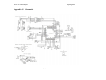
Appendix C: Schematic
C-1
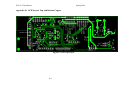
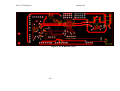
Appendix D: PCB Layout Top and Bottom Copper
D-1
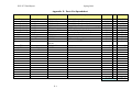
Appendix E: Parts List Spreadsheet
E-1
Appendix F: Software Listing
F-1
Appendix G: FMECA Worksheet
G-1
-ii-
ECE 477 Final Report
Spring 2009
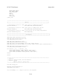
Abstract
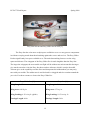
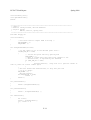
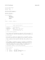
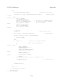
FlySpy is a hobby aircraft modified to fly and take pictures under its own control. It uses
GPS for navigation, flying along a path of waypoints defined on a microSD card and triggering
the onboard camera at defined points. Autonomous flight control is achieved using inertial
sensors (accelerometers and gyros) as feedback, while a switch on the remote control allows
manually-controlled flight for takeoff and landing.
1
ECE 477 Final Report
Spring 2009
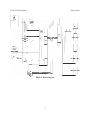
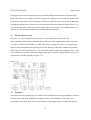
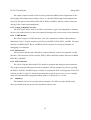
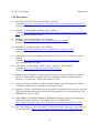
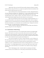
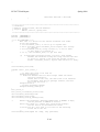
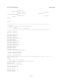
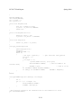
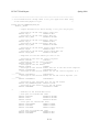
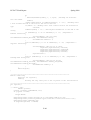
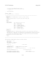
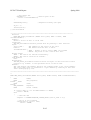
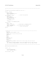
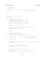
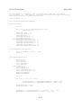
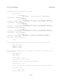
1.0 Project Overview and Block Diagram
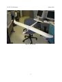
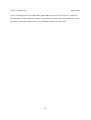
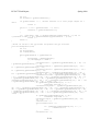
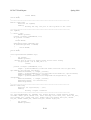
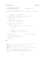
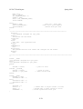
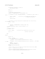
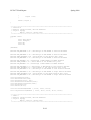
The FlySpy, as built by our team, is a modification of the Easy Glider Pro hobby aircraft
from Multiplex Modelsport. The control system is primarily constructed on a printed circuit
board (PCB) mounted within the plane’s “cockpit”. The pitch and roll of the plane are calculated
using a three-axis accelerometer and a two-axis gyro, which are used in the autopilot feedback
loop to stabilize the aircraft. Flight surface servos and the propeller throttle are controlled using
PWM, either from the microcontroller or from the RC receiver. A consumer digital camera and
ultrasonic rangefinder are mounted on the bottom of the fuselage. The camera’s on/off switch
and shutter are wired to pins on the microcontroller, allowing the controller to take photographs
automatically. The rangefinder is to support fully autonomous landing, although this is not
implemented. The guidance system uses an FV-M8 GPS module to get a position, heading, and
velocity measurement 5 times a second. GPS waypoints are read in from files on a FATformatted microSD card, and flight data is written back out.
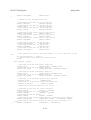
Essentially, FlySpy is an aerial reconnaissance platform. It allows a user to take pictures
of ground locations given only their GPS coordinates, making it easy to survey areas that the
user cannot travel to himself.
2
ECE 477 Final Report
Spring 2009
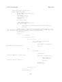
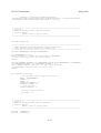
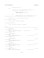
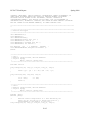
Fig 1.1: Block Diagram
3
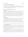
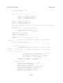
ECE 477 Final Report
Spring 2009
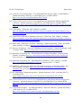
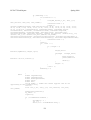
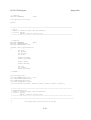
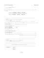
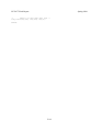
Fig 1.2: The FlySpy
4
ECE 477 Final Report
Spring 2009
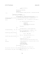
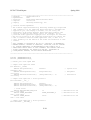
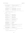
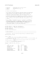
2.0 Team Success Criteria and Fulfillment
1. Ability to control airplane’s control surfaces and throttle
Status: Completed.
2. Ability to read/write flight information to non-volatile memory
Status: Completed. Reading from and writing to files on a FAT filesystem on the
microSD card is supported and used extensively in our project.
3. Ability to take pictures with onboard camera
Status: Completed. The camera is completely mounted on the plane, which bears the
load and stays in the air.
4. Ability to autonomously navigate to GPS coordinates
Status: Incomplete. We have not had sufficient time to tune the control algorithms to get
the plane airborne under its own control.
5. Ability to calculate orientation of the vehicle
Status: Completed.
5
ECE 477 Final Report
Spring 2009
3.0 Constraint Analysis and Component Selection
3.1
Design Constraint Analysis
In designing the full layout for FlySpy, we observe various constraints that limit our project
to an extent. The most critical is that our microcontroller must have enough pulse width
modulation channels to support the output to all the controls of the airplane. In addition to the
number of PWM channels, we also need to make sure that the channels have a high enough
resolution to smoothly control the plane’s surfaces. In order to calculate the orientation of the
aircraft, we have to have a lot of ATD channels that will convert data from accelerometers and
gyroscopes in multiple axes. Another big issue is the size and weight of the included
components. The Easy Glider Pro has a decent amount of space in the cockpit but a lot of this
space is filled by the RC components. This means that items that we want secured in the cockpit
will have to be small, but pieces that are not critical to be close to the microcontroller will have
the option of being mounted to the outside shell of the airplane. We must also be mindful of the
weight of the components that we use because too much weight will not allow the plane to fly.
3.2 Computation Requirements
A good amount of calculation will be needed to both calculate the current orientation of the
aircraft based off accelerometer and gyroscope inputs and calculate the needed orientation of the
aircraft from the GPS destination and current location. In calculating the current orientation off
of the accelerometer and gyro data, we find ourselves needing quite a few floating point
operations. We approximate 100 floating point operations for every update at a 50 Hz interval
[6]. Assuming that we go with a very low-end microcontroller without native floating point
hardware (such as Microchip’s PIC line), we conservatively estimate that each floating point
operation will take 100 clock cycles. This means that we need a processor of at least 500 kHz to
sustain the updates. Based on these estimates, we concluded that an integer-only processor of
with a clock of 1MHz or more would be sufficient to maintain the orientation calculations.
Once we have successfully done the navigation and orientation calculations, we then will
set the control surfaces so that the current orientation will approach the desired orientation. We
will also have to write the current data to the SD Card for flight logging. These should not
require much CPU power compared to the orientation calculations.
6
ECE 477 Final Report
Spring 2009
We do not expect to need much RAM on the chip, as there are no large data structures being
manipulated in-memory. Program memory is not expected to be particularly constraining.
3.3 General Purpose Digital I/O Requirements
In the design for FlySpy, the camera will be the only device that will use the generalpurpose I/O ports. We assume that the camera will need to make use of only a few of these. We
will need to output control of the camera’s on/off switch and shutter pushbutton, and we will
need to relay back to our microcontroller a line which signifies the on/off status and the picture
ready status of the camera. We will also need an input pin to the microcontroller that will signify
if the plane is being controlled from the manual pilot or by its own signals.
3.4 Interfaces and On-Chip Peripheral Requirements
On-chip peripherals are plenty in our design. We will make use of 5 channels of Pulse Width
Modulation. We are requiring that these channels have 16-bit resolution because the control
surface’s servos can only tolerate a small range of pulse width and with 8-bit resolution we will
not be able to make very accurate deflections. In order to record the flight path of the manual
pilot when in manual mode, we will need to intercept the PWM signals coming from the
receiver. To do this, we will need 5 input capture timer channels to record the pulse widths and
write them to memory. The GPS receiver module will communicate through SCI interface as
well as another SCI interface for debugging purposes. SPI interfaces will be needed to read and
write to and from the SD Card and also to communicate with the barometer to receive altitude.
To interface with all of the sensors that will need to calculate the orientation of the aircraft, we
estimate making use of 6 channels of 10-bit ATD. This includes 3 axes from the accelerometer
chip, 2 axes from the gyroscope chip, and a range finder.
3.5 Off-Chip Peripheral Requirements
In FlySpy, a lot of off chip devices are required to provide important information to the
microcontroller so that it may compute and execute a flight path. For to acquire this information,
we will need a GPS Receiver, three axis accelerometer, two axis gyroscope, barometer, and a
rangefinder. A GPS receiver is needed to provide position and heading information. The
receiver must have a minimum accuracy of about 5-6 meters so that we capture a picture of the
7
ECE 477 Final Report
Spring 2009
GPS coordinate within our picture. The barometer will be used as an altimeter, providing
accurate measurements of pressure enough to stay within a +-1m range of flight altitude. The
gyroscope will be used to sense angular rotation of the aircraft’s pitch and roll. The
accelerometer will be used to correct the error of the gyroscope’s accumulation of rotation data
overtime. The rangefinder will be used to sensor when the aircraft is close to the ground enabling
it to land correctly.
Aside from the components that we will need for the autopilot, we will also need the
general components to the RC aircraft. This includes the airframe, servos, receiver/transmitter
pair, motor, and speed controller.
3.6 Power Constraints
Battery power in FlySpy is critical so that we may have enough power to control the RC
components and our autopilot devices. Once all of these devices are added to the plane, it will
weigh more and need more power than the plane as it is out of the box. The motor, being the
component with the most power consumption, will need enough power to handle this weight
over the duration of time that we need to travel a reasonable flight path. The battery itself will
add weight to the plan and usually the more powerful it is, the more it will weigh.
In choosing a battery we must be mindful of its weight, flight time, and size. Size is also
critical because it will be placed in the cockpit; any space consumed by the battery is less space
for the autopilot. The battery must be able to source more than +5 V and 2.75 A. The servos,
motor and receiver will run off of a +5 V rail; the motor is expected to draw about 2 A and the
servos 150 mA each. The other components will run off a +3.3 V rail stepped down from the +5
V rail and are roughly estimated to draw 150 mA.
3.7 Packaging Constraints
The packaging on FlySpy is a major concern. The aircraft that we have selected was made
just to withhold the RC components for a manual pilot. It is also molded on the inside so that
pieces may have compartments to fit into without sliding. Knowing this, we have major
constraints on space for items that will be placed on the interior of the aircraft. We estimate
8
ECE 477 Final Report
Spring 2009
dimensions close to 1.5 in. X 1 in. X 5 in. The pieces that will be placed internally also have to
be placed in a way that they do not disturb the servos or servo rods that sit in the cockpit.
For the components, that can be far away from the microcontroller may be placed on
the exterior of the aircraft. This will be beneficial to use with use of the GPS receiver and the
camera. The GPS receiver may be placed on top of the fuselage and close to the rudder. This unit
can be used to counter balance the components that we insert internally, therefore helping to
retain a good aerodynamic center. The camera itself will need to be mounted to the bottom of the
aircraft. It must be placed at the aerodynamic center because we do not want to add more weight
to counter react it and adding to the total weight.
3.8 Cost Constraints
Currently, there aren’t any solutions that give you a airplane with built in autonomous
abilities. On the other hand, they do commercially sell autopilot units that you may insert into
your own plane. MicroPilot markets themselves as the world leaders in miniature UAV
autopilots so we will compare our design with their unit alone. Their low end autopilot controller
that they market as “Disposable control...” is $2000 dollars per unit. We are aiming for a total
cost (plane, controller, computing hardware) of under $1000.
3.9
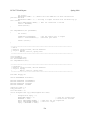
Component Selection Rationale
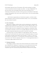
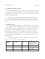
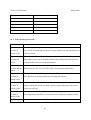
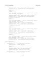
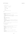
The microcontroller was one of the more difficult parts to select due to the bewildering
number of choices available from various manufacturers. The core requirements were as follows:
Type
#
Comments
PWM Outputs
5
One for each aircraft control signal (two ailerons, elevator, rudder,
throttle). While a controller with only 4 signals available would be
doable by running both ailerons off the same PWM signal, this choice
would slightly limit the flexibility of the aircraft's control; for
example, the ailerons could not be used as flaps for takeoff and
landing. This is not critical to fulfilling any PSSCs, but a full 5
channels is a "nice to have" feature.
Input Compare
5
For reading the PWM control signals from the R/C receiver
9
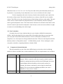
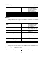
ECE 477 Final Report
A/D
8+
Spring 2009
The microcontroller will interface with a 3-axis accelerometer, a 2axis gyro, and possibly some other analog devices, such as a compass,
barometer, or rangefinder.
SPI
1
Communicate with the SD card.
Digital I/O
3+
"Spare change" pins to control the camera.
SCI ports
2
One to communicate with the GPS module, and one for general
debugging/PC interfacing.
Debug interface
1
JTAG, ICD-2, or otherwise
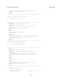
In addition, voltage was a serious consideration, as it determines which peripherals can be
interfaced directly to the microcontroller and which ones require conversion logic. Direct
interfacing was preferred. The SD card operates at 3.3v and uses signal levels in that range.
Similarly, the GPS unit can use 3.3v signaling. Bench testing of our airplane kit's hardware
shows that the servos and speed controller should work fine with a 3.3v. This made a 3.3v device
a viable option, conveniently reducing power consumption for the microcontroller itself. The
R/C receiver gives 5v PWM signals, which could require some signal conditioning.
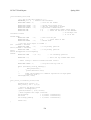
PIC24FJ128GA106 [1]
MC9S12HZ128CA [2]
- 5 16-bit PWM channels (via Output
- 4 16-bit PWM channels
Compare)
- 9 Input Compare channels
- 8 Input Compare channels
- Internal Oscillator
- Internal Oscillator
- 16 A/D channels at 10bits
- 16 A/D channels at 10bits
- ICD debugging interface
- BDM debugging interface
- Current draw: up to 24mA
- Current draw: 65 mA with everything
enabled
- 2.2v to 3.6v operating voltage means that it
- Operates at 5v. This certainly means that
can be run at 3.3v and thus interfaced directly
signal conditioning would be required on the
to all of the peripherals.
SPI interface, and probably the SCI interface to
10
ECE 477 Final Report
Spring 2009
the GPS unit. A 3.3v rail is still necessary to
power the various peripherals, but the analog
inputs can measure 0-3.3v perfectly fine, with
the consequence that the resolution will be
worse.
- Can tolerate up to 6V on digital inputs. This
- Can tolerate 5v digital inputs due to its
will allow the receiver's PWM signals to be fed
operating voltage.
directly to the input pins on the
microcontroller.
- Unit cost is around $5.
- Unit cost is around $10.
- William is already familiar with the
- Group has decent familiarity with 9S12
Microchip development environment.
processors and peripherals from 362.
Due primarily to the voltage level issue and unit pricing, we decided to buy the PIC.
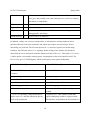
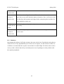
For the airplane, we stayed within the Multiplex brand of aircrafts. This is because of
the ELAPOR material that their products used which is popular for its durability and easy
reconstruction after crashes. When we narrowed our search down to two of their airframes, we
were torn between the Easy Star and the Easy Glider Pro. When comparing the two we were
concern about three main differences. The Easy Star has a propeller that sits up in the middle of
the plane which was appealing because if we crashed the plane, the engine or propeller wouldn’t
be the first to hit. The Easy Glider has its propeller and motor in the front but has a bigger motor
to withstand more weight. The size of the cockpit was another aspect we looked at closely as
depicted below:
11
ECE 477 Final Report
Spring 2009
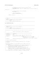
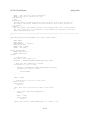
Easy Star in front and Easy Glider Pro in back [5]
The Easy Star has a lot more cockpit space available to us so we may put our components
in without worrying much about them brushing against the servos and receiver. The Easy Glider
Pro has significantly less space available to us. The main determining factors were the wing
spans and ailerons. The wingspan of the Easy Glider Pro is much lengthier than the Easy Star.
The larger the wingspan, the more stable our flight will be without our microcontroller having to
give much correction. Also the Easy Star does not have ailerons, which is a major downfall.
Ailerons give us the capability to make direct and sharp turns but without them you may only
turn with your rudder. The rudder turn is not ideal and is a sluggish and slow rotation around the
yaw axis. For these reasons we choose the Easy Glider Pro.
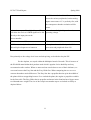
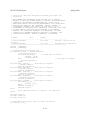
Easy Glider Pro [3]
Easy Star [4]
Wing Length: 72 in.
Wing Length: 54 in.
Wing Area: 645 Sq in.
Wing Area: 372 sq. in.
Wing Loading: 6.25 oz/sq ft. (glider)
Wing Loading: 10.76 oz./sq. ft.
Fuselage Length: 44 in.
Fuselage Length: 34 in.
12
ECE 477 Final Report
Weight (English): 34 oz (Electric)
Spring 2009
Weight (English): 24 oz.
Weight (Metric): 29 oz. (Glider)
13
ECE 477 Final Report
Spring 2009
4.0 Patent Liability Analysis
The possible infringement could be occurred in the algorithm of controlling the airplane’s
position and orientation using appropriate sensors and GPS system, controlling camera to take
appropriate photo at the projected GPS coordinates, and switching the control authority between
FlySpy system and remote controller. As the demand on the UAV technology has been high due
to military purpose, a number of related patents were researched and the following 3 patents
were the most concerned ones in the each category.
4.1
Results of Patent and Product Search
4.1.1 Programmable autopilot system for autonomous flight of unmanned aerial vehicles
U.S. Patent No. 7302316 [7]
Filing Date: November 27, 2007
Abstract: A system and method for providing autonomous control of unmanned aerial vehicles
(UAVs) is disclosed. The system includes a ground station in communication with an unmanned
aerial vehicle. The method for providing autonomous control of a UAV includes methods for
processing communications between the ground station and UAV. The method also includes
process for estimating the attitude of the UAV and autonomously maintaining its altitude within
a desired threshold, process for autonomously orbiting about a specified point in space, and
process for an autonomous takeoff and landing of the UAV.
Claims for Possible Infringement:
Claim1. An autopilot control system for an unmanned aerial vehicle, comprising: a ground
station; and an on-plane control system, comprising: a processor; memory in electronic
communication with the processor; three accelerometers in electronic communication with the
processor; three rate gyroscopes in electronic communication with the processor; an absolute
pressure sensor in electronic communication with the processor; a differential pressure sensor in
electronic communication with the processor; a global positioning system in electronic
communication with the processor; a transceiver in electronic communication with the processor
to receive and transmit wireless signals; and a power source that supplies power to both the onplane control system and to an actuator used to propel the unmanned aerial vehicle.[7]
14
ECE 477 Final Report
Spring 2009
Claim4. The autopilot control system as defined in claim 3, wherein the on-plane control system
further comprises a bypass circuit that allows the unmanned aerial vehicle to be controlled by the
RC controller instead of the on-plane control system.[7]
4.1.2 Precision Approach Control U.S. Patent Application No. 2008/0071431 [8]
Filing Date: March 20, 2008
Abstract: An aircraft control system for operations close to the ground includes a camera having
a rangefinder for measuring the azimuth, elevation and slant range from a fixed point on the
aircraft relative to a selected target point on a surface below the aircraft, a navigation system for
measuring the latitude and longitude of the aircraft on the surface, a computer for computing the
position of the fixed point on the aircraft relative to the target point from the respective
measurements of the camera and the navigation system, and a controller for controlling the
movement of the aircraft.
Claims for Possible Infringement:
Claim1. An aircraft command and control system, comprising: a camera, including a rangefinder,
disposed aboard the aircraft for measuring an azimuth angle, an elevation angle and a slant range
from a fixed point on the aircraft relative to a selected target point on a surface located below the
aircraft; a navigation system disposed aboard the aircraft for measuring a latitude and a longitude
of a point on the surface that is disposed perpendicularly below the fixed point on the aircraft; a
computer for computing the position of the fixed point on the aircraft relative to the target point
on the surface from the respective measurements of the camera and the navigation system; and, a
controller for controlling the movement of the aircraft such that the fixed point on the aircraft is
positioned at a selected azimuth angle, elevation angle and slant range above the selected target
point on the surface.[8]
Claim 4: “The system of claim 1, wherein the navigation system comprises a Global Positioning
Satellite (GPS) system, an Inertial Navigation System (INS), or both a GPS and an INS.” [8]
Claim 5: “The system of claim 1, wherein the aircraft comprises a helicopter or an aerial
vehicle.”[8]
15
ECE 477 Final Report
Spring 2009
4.1.3 Anti-hijacking system operable in emergencies to deactivate on-board flight controls
and remotely pilot aircraft utilizing autopilot U.S. Patent Application No.
2004/0079837 [9]
Filing Date: April 29, 2004
Abstract: In an anti-hijacking system for autopilot equipped aircraft, a transceiver communicates
with at least one remote guidance facility. A panic button is activated by flight crew in case of
hijacking. A manager is coupled to the transceiver and the panic button, as well as existing
avionics including the aircraft's master computer and autopilot. The manager recognizes
predetermined override inputs, such as activation of the panic button or receipt of override
signals from the remote guidance facility. Responsive to the override input, the manager
deactivates on-board control of selected aircraft flight systems and the autopilot system, and
directs the autopilot to fly the aircraft to a safe landing.
Claims for Possible Infringement:
Claim1. A method for preventing hijacking of an aircraft, comprising operations of: providing a
hijacking intervention module aboard an aircraft having an autopilot system; the module sensing
a predetermined override input; responsive to the sensing of the predetermined override input,
the module performing operations comprising: deactivating on-board control of predetermined
aircraft flight systems; deactivating on-board control of the autopilot system; directing the
autopilot system to fly the aircraft to a landing. [9]
Claim2. The method of claim 1, the operations responsive to the sensing of the predetermined
override input further comprising: receiving manual commands from at least one remote
guidance facility, the manual commands comprising instructions to manually manipulate
specified aircraft flight systems. [9]
4.2
Analysis of Patent Liability
4.2.1 Analysis of Liability involving Programmable autopilot system for autonomous flight
of unmanned aerial vehicles
In Claim1, it states that components such as gyroscope, accelerometer, memory, pressure sensor,
GPS receiver, and bypass module are all connected to the processor. The components used and
how components are mapped is very similar to our design because the sensors are needed for
specific measurement of in-flight information. Although our system utilizes single gyroscope,
16
ECE 477 Final Report
Spring 2009
accelerometer, and pressure sensor, the patent states that three of gyroscopes and accelerometer,
two of pressure sensors are used for the calculation of plane’s altitude and orientation. This
would be a great reason that our system is different from theirs since we are utilizing less number
of components for the system with the same objective which is to control airplane as unmanned.
The calculation algorithm will be different as we have different number of sensors and the main
loop depicted in patent is also different
4.2.2 Analysis of Liability involving Precision Approach Control
In Claim1, the patent states that it utilizes the GPS navigation system to approach to the
projected spot of photograph. Although both system use GPS navigation system, the difference
between the patent and FlySpy is the algorithm to determine when to take the photo. FlySpy
solely depends on the GPS information and pressure sensor while the patent uses the laser
rangefinder for more accurate measurement. The laser rangefinder works with azimuth lens on
camera to find the best angle and distance for photo shot. FlySpy’s photo taking system does not
include laser range finder or azimuth lens and therefore it does not cause an infringement.
4.2.3 Analysis of Liability involving Anti-hijacking system operable in emergencies to
deactivate on-board flight controls and remotely pilot aircraft utilizing autopilot
In Claim1, the patent explains the switching the control of the airplane by an emergency push
button and this is very similar to the bypass module of FlySpy. As supposed that the pilot is the
autonomous flight control system and hijacking is the malfunction of the autopilot, FlySpy
should switch its control authority to the remote controller. However, FlySpy’s module does not
support the control from multiple stations and the patent’s statement restricts the purpose of
invention to the passenger planes.
4.3
Action Recommended
To avoid the infringement on [7], FlySpy has to develop the algorithm that can achieve the goals
without following the sensor selections in the patent. If FlySpy can accomplish the goal
successfully with less number of components and the equal accuracy, the technology can be
patented as well. To avoid the infringement on [8], FlySpy has to use the camera strictly and
approach to the destination for photo taking by GPS guidance only as it is planned. Although the
17
ECE 477 Final Report
Spring 2009
similarity of the design is found in the patent and FlySpy’s control bypassing module, the
targeting air plane is different and the patent [9] states the exclusive use in the hijacking
circumstance of passenger planes and the interaction between pilots and ground facility is very
important part in the decision process as claimed in 1 and 2 of [9]. Therefore, there will be no
infringement on [9].
4.4
Summary
As the demand on unmanned aerial vehicle was high, there were a number of patents on UAV
inventions. Through this reports, the closest three patents showed some similarities and
differences. Even if three patents work the same functions in UAV, the design plan showed
enough design dissimilarity to avoid from the infringement on existing patents.
18
ECE 477 Final Report
Spring 2009
5.0 Reliability and Safety Analysis
Due to the range and potential for loss of control, safety is an issue not only for the user but
also for others who may be within flight range. Software error is the primary concern; because of
the complexity of the software design, software error is a far likelier culprit in erratic behavior or
loss of control than hardware failure.
This analysis disregards the standard components on board the RC airplane: servos,
motor, receiver, battery, step-down converter (providing +5 V to power the servos, motor and
receiver off of the battery) and only takes into account the components added in this design
project.
5.1
Reliability Analysis
The most complex component in the design is the PIC24FJ256GA110 microcontroller. Most
of the other components, except for the GPS receiver, are fairly simple in comparison. During
testing, we did not observe any components that ran hot with a reasonable load. Because of the
relative irrelevance of these considerations, “mission-critical” components were chosen in
additional to the microcontroller. The PI3V512 multiplexor was chosen because it controls
switching between manual and autonomous modes. The LTC1174 buck converter was chosen
because all components except the motor, servos and receiver are powered on the +3.3V rail.
Microcontroller
The microcontroller model from section 5.1 in the handbook was used [10]. With this
model, λ P = (C1π T + C 2π E )π Q π L failures per 106 hours.
Parameter
name
Description
Value
C1
πT
Die complexity
Temperature coeff.
.28
.29
C2
Package Failure Rate
.053
19
Comments regarding
choice of parameter value,
especially if you had to
make assumptions.
16 bit
TJ = -40 to +125 C from
page 260 of datasheet [11];
estimate +50 C
SMT, ~128 pins
ECE 477 Final Report
Spring 2009
πE
Environment Factor
4.0
πQ
Quality Factor
10
πL
Learning Factor
1.0
Failures per million hours
Mean time to failure (MTTF) in years
Entire design:
Assume ground mobile
since the plane operates
fairly close to the ground
(no typical stresses of
airborne environments)
Commercial product
>= 2.0 years in production
2.932
38.908
Multiplexor
The digital MOS model from section 5.1 in the handbook was used [10]. With this model,
λ P = (C1π T + C 2π E )π Qπ L failures per 106 hours.
Parameter
name
Description
Value
C1
Die complexity
.010
πT
Temperature coeff.
5.6
C2
πE
Package Failure Rate
Environment Factor
.0087
4.0
πQ
Quality Factor
10
πL
Learning Factor
1.0
Failures per million hours
Mean time to failure (MTTF) in years
Entire design:
Comments regarding
choice of parameter value,
especially if you had to
make assumptions.
~100 transistors (each 2:1
mux = 3 NAND gates = 12
transistors, x 5 = 60 each
way because bidirectional)
TJ = +150 C from page 2 of
datasheet [12]
SMT, ~24 pins
Assume ground mobile
since the plane operates
fairly close to the ground
(no typical stresses of
airborne environments)
Commercial product
>= 2.0 years in production
.908
125.72
Buck Converter
The linear MOS model from section 5.1 in the handbook was used [10]. With this model,
λ P = (C1π T + C 2π E )π Qπ L failures per 106 hours.
Parameter
Description
Value
20
Comments regarding
ECE 477 Final Report
Spring 2009
name
C1
πT
Die complexity
Temperature coeff.
.010
58
C2
πE
Package Failure Rate
Environment Factor
.0026
4.0
πQ
Quality Factor
10
πL
Learning Factor
1.0
Failures per million hours
Mean time to failure (MTTF) in years
Entire design:
choice of parameter value,
especially if you had to
make assumptions.
<100 transistors
Tj=Ta+(PD*110ºC/W) from
page four of datasheet [13]
SMT, ~8 pins
Assume ground mobile
since the plane operates
fairly close to the ground
(no typical stresses of
airborne environments)
Commercial product
>= 2.0 years in production
5.904
19.33
These conclusions appear reasonable. The calculations suggest that the components are reliable,
as would be expected. Based on this analysis, one way to improve the reliability would be to
select a microcontroller with fewer pins.
5.2
Failure Mode, Effects, and Criticality Analysis (FMECA)
Three criticality levels were defined (based on in-flight operation rather than benchtop testing):
In the High criticality level, the plane either crashes or cannot be returned to manual
control. In the latter case, the plane will simply fly autonomously until the battery runs down or
it crashes. Not only is a crash condition potentially injurious to the project, but in addition, it
could present a danger to the user and any individuals within flight range. The plane is made of
foam, but it is equipped with a front-mounted plastic propeller. Because of the danger to the user
and the potential for destruction of the product, a hardware failure rate λ of 10-9 seems advisable.
In the Medium criticality level, the plane loses its autonomous control functionality;
however it can still be flown manually. The plane must be returned to manual control. This
category assumes that flight stability can be reachieved in the wake of autonomous control
failure; if it cannot, any event in this category would need to be upgraded to High criticality
level. The selection of an appropriate failure rate is somewhat arbitrary; however, a failure rate of
λ = 10 per million hours would result in an MTTF of about 11.4 years, longer than the expected
use of the product.
21
ECE 477 Final Report
Spring 2009
In the Low criticality level, the project experiences some loss of non-critical
functionality. For example, the plane could not take photos. A failure rate of λ = 35 per million
hours is fairly generous for low criticality failures and would result in an MTTF of about 3.3
years. Most point and shoot cameras probably have a lifetime of about 3-5 years.
As an aside, intelligent engineering would have dictated using a multiplexer with a +5
V supply; the current multiplexer is powered on the +3.3 V rail. If the +3.3 V power supply
circuit fails, the plane will necessarily crash because no PWM signals can be switched. However,
had the mux been powered on the +5 V rail along with the servos, motor and receiver, manual
control could have been maintained.
5.3
Summary
In summary, software error is the biggest threat to the safety and reliability of the
project. Physical reliability of the hardware is a secondary focus. Aside from the microcontroller
and GPS module, few components would be considered complex and none of the components
run very hot under testing with a reasonable load. The plane is comparatively safe to a user
testing it in lab. However, in-flight operation introduces a risk of injury to the users and others in
the vicinity as well as damage to the body of the plane. The best safety precaution is probably to
keep the potential flight area as clear of people as possible and to stay alert.
22
ECE 477 Final Report
Spring 2009
6.0 Ethical and Environmental Impact Analysis
Ethically, the FlySpy presents some hazards to the user, as it is an airborne vehicle with a
fast-spinning prop; the risks are exacerbated by its autonomy. FlySpy also has obvious civil
privacy implications. There may also be military uses for FlySpy; however, since it is unarmed,
we do not think the ethical implications are overly pressing.
The drone has environmental concerns similar to most electronic consumer devices.
However, as FlySpy is modified from a commercially available hobby model aircraft, FlySpy's
airframe provides a disposal concern beyond that already posed by the onboard electronics. Due
to the risk of loss, the risk of improper disposal is somewhat greater than that of, say, an iPod.
6.1
Ethical Impact Analysis
6.1.1 Consumer Safety Hazards
FlySpy is A) airborne, B) autonomous, and C) propeller-powered. As such, it poses a
significant risk of physical harm to a careless user.
Being airborne and highly mobile, FlySpy could collide with an object and potentially
cause damage. Possible objects include: cars, windows, pets, and humans. The momentum of the
plane and the sharp, fast-spinning, hard plastic propeller can both contribute to damage or injury.
The propeller deserves special consideration. It can seriously injure a human who
sticks a finger into its arc while it is spinning. On top of being sharp, fast, and painful on impact,
it is also difficult to see while in operation. Prop-related injuries are a major hazard of all aircraft
that involve spinning blades; some of the potential mitigations of the risk are as follows:
1. Brightly color the blade tips to make the arc's edge more visible (Team 8: OCHO is doing
exactly this). Also, color the nose cone so that it is easier to notice when it is spinning.
2. Warnings in the user manual to keep one's fingers out of the blade arc as much as
possible and to keep the propeller assembly detached from the motor until ready to fly.
23
ECE 477 Final Report
Spring 2009
3. Brightly colored warning sticker near the nose with a picture warning of the risk.
4. After boot up, the speed controller itself requires the throttle input to be set to 0 before it
will “arm” and start spinning the motor in response to nonzero throttle inputs.
5. We specifically selected a model plane with a prop mounted on the nose, as opposed to in
the rear of the plane. This makes it easier to hand-launch the plane without passing one's
hand through the propeller arc.
6.1.2 Loss of Plane Control
FlySpy has a couple classes of “loss of plane control” conditions that could pose risks.
Under manual control, it can easily be crashed by an inexperienced pilot; as such, the user
manual should note that this plane is not trivial to operate and that the user should take lessons
from a local hobby group before trying to fly the plane solo.
Under autonomous control, the plane could fly off “into the wild blue yonder”, out of
range of the radio receiver. This could result in a crash when the batteries run out, or in total loss
of the plane. We designed the autopilot override such that the plane will maintain steady flight
when out of radio range, and be reliably and quickly switchable to manual control when in radio
range.
6.1.3 Privacy Risks
FlySpy, being an aerial photography/reconnaissance device, poses obvious privacy
risks. Users could easily misuse it to spy on their neighbors. While we are not aware of the
legality of aerial photography, using FlySpy to spy on others against their will is certainly
unethical. Unfortunately, we can think of no reliable way of preventing such use. We can only
add dire warnings in the user manual about legal consequences.
FlySpy could also be used by police forces to spy on private citizens, which raises
civil rights issues, particularly in nations with poor human rights records. Again, we have no
direct means of preventing abuse; the best we could do is to refuse to sell to customers in
countries that have records of civil rights abuse, but we have little ability to prevent resale or
proxy purchasing. We would probably have to rely on United States export regulations.
6.1.4 FAA Regulations
24
ECE 477 Final Report
Spring 2009
The Federal Aviation Administration has rules that affect model aircraft, including
FlySpy. In particular, a pilot must have an (inexpensive) FAA permit in order to legally fly the
aircraft; this would be noted in the user manual.
Also, the FAA restricts flight in certain areas, such as airport approach and takeoff
corridors and security-related no-fly zones. We cannot directly prevent the user from flying the
plane into such zones under manual control (at least, not without compromising the reliability of
the manual/autonomous switching system), but we could conceivably load GPS coordinates of
no-fly zones into the firmware to prevent the user overflying them in autonomous mode. This
could be difficult to keep up-to-date, however. As such, the only option may be to simply note
the existence of such zones in the manual and to remind the user to check with local aviation
authorities, including a disclaimer that we are not responsible for user misuse.
6.2
Environmental Impact Analysis
6.2.1 Material Disposal
FlySpy has three major classes of material posing environmental concerns: the
airframe, the control circuitry, and the LiPo battery. Since the plane is meant to be used outdoors
and has a nontrivial chance of getting lost outdoors (the “wild blue yonder” failure mode), the
risk of its materials ending up out in the woods somewhere is higher than that of most other
consumer devices.
The airframe is constructed of a material called “Elapor”. Elapor is extremely
lightweight, yet very robust. However, being essentially Styrofoam, it is not really recyclable,
and so will end up in a landfill [14]. This waste is somewhat mitigated by the fact that FlySpy is
not a throw-away product, so each unit is expected to be used for years. Also, the choice of
material both reduces the likelihood of damage, as Elapor is much less brittle than balsa wood,
and makes damage to the airframe easy to repair using tape and glue, reducing the number of
units that will get thrown away due to damage. In the event that the plane gets lost, the Elapor
will be a pollutant, and will take a very long time to decompose. To possibly mitigate this
environmental hazard, we could switch to something like a balsa wood airframe, but that would
make FlySpy more prone to damage, or to a hard plastic airframe, which would be heavier.
25
ECE 477 Final Report
Spring 2009
Like those of virtually all electronic devices, FlySpy's circuit boards and electronic
components are an environmental concern. Most of the parts could be manufactured in an RoHScompliant way; many of our components are already RoHS-compliant. However, lead-free parts,
particularly lead-free solder, are known to affect reliability, so it may not be worth the tradeoff
[15]. The components themselves are all standard electronic parts; there is nothing particularly
unusual about any of the electronics, so any standard electronics recycler could process them. As
with the airframe, there is a decent risk that the electronic parts could end up in the environment
due to plane loss.
The lithium polymer (LiPo) battery used in FlySpy could be a major environmental
problem, particularly if it is damaged and/or lost during a crash. The user should be encouraged
to safely dispose of the battery at a battery drop; perhaps the user could get a new battery at a
discount if he trades in the old one in the process.
In short, the environmental concerns of FlySpy are fairly large, and primarily relate to
safe disposal.
6.2.2 Wildlife Interaction
Bird strikes are a fairly common problem in aviation, so FlySpy could have the same
issue. As a bird is yet another “object” with which the propeller does not get along well, serious
injury to wild fowl could result from a collision. There is little that we can do to mitigate this risk
in our design and documentation; fortunately, such collisions are relatively rare to start with.
6.3
Summary
FlySpy has nontrivial safety hazards, but they are not so great as to be dangerous to
your average careful user. It is, however, certainly not a product for children. There are some
ethical issues relating to how FlySpy is used, but they are not overwhelming. The environmental
impact is potentially very serious; however, there is not a lot we can do beyond incentivizing
proper disposal.
26
ECE 477 Final Report
Spring 2009
7.0 Packaging Design Considerations
Flyspy’s packaging is going to be the plane called Easy Glider Pro and minimal modification to
the plane is going to be done to avoid the drastic change in aerodynamic structure of the plane.
The weight of the circuit board will be light and therefore it would not change the balance of the
system very much but the weight of the camera can ruin the balance of the air plane therefore it
should be placed at very appropriate spot.
Since we expected that the additional weight would require more power of motor, we ordered a
motor with extra capacity.
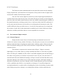
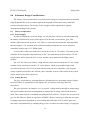
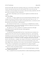
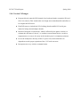
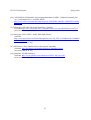
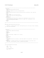
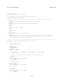
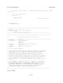
Figure 1. Micro Pilot’s Software
7.1
Commercial Product Packaging
After searching online, two competitors to our system were
found. One is Micro Pilot MP-2028 from Micropilot and
another
is
Kestrel
Autopilot
from
Procerus
Technology.They provide the circuit that can be installed to
RC-scale air plane to guide the plane to fly through preprogrammed GPS coordinates. Their packaging is amazing
in terms of their size and weight of the circuit. Those
products which are similar to our system had every
component on the board but our system will use cables to connect to many components and
locate them on the better place. They consist of similar components and the object of the system
is the same therefore they are appropriate examples to compare our system.
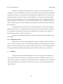
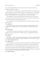
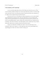
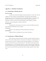
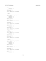
Figure 2. Micro Pilot’s Circuit
7.1.1 Micro Pilot MP-2028
Micro Pilot provides a handy solution to turn any RCscale plane into unmanned aerial vehicle with single
circuit installation. The circuit only weighs 28 grams
including 3-axis gyros, accelerometers, GPS, pressure,
altimeter, pressure and airspeed sensors [16]. It also
provides explanatory manuals and videos for installation
and flight operation. The circuit size is 4” x 1.5” x 0.6”
27
ECE 477 Final Report
Spring 2009
which is very small so that it can fit in our plane without any problem. Micropilot’s circuit seems
much optimized since they could put all sensors on the board and still the size is very small. It
also provides flight management software and it costs about $2,000.
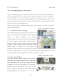
7.1.2 Procerus Kestrel Autopilot
The size of Kestrel Autopilot developed by Procerus
Technology is 2” x 1.37” x 0.47” and the weight of
Auto pilot is only 16.7 grams [17]. Autopilot has a duallayer PCB and has most sensors on the board without
GPS receiver. Even though they did not include GPS
receiver, its cost is about $5,000. However, it is smaller
than Micro Pilot and it has wi-fi connectivity to the
ground station. It has a very compact size and it was
Figure 3. Autopilot’s Circuit
developed with military purpose. Since we are now
going to use the dual-layer PCB, our design would be
more similar to the Micro Pilot than Autopilot.
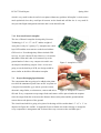
7.2
Project Packaging Specifications
The components that are going to be added to the plane
to realize the unmanned system into our RC air plane are
a single microcontroller, gyro sensor, pressure sensor,
ultrasonic range finder, accelerometer, camera and micro
Figure 4. Autopilot’s Circuit #2
SD card. Every component except range finder and camera will be placed under the airplane
since the range finder has to measure the distance between the plane and the ground and the
camera has to take photos of the ground.
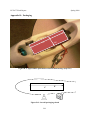
The circuit board which is going to be placed in fuselage will be smaller than 1.5” x 5” x 1”. As
depicted in Figure B-1 and B-1 in Appendix B, the available area in the fuselage is enough for
every component’s arrangement and we do not have any concern on the available space.
28
ECE 477 Final Report
Spring 2009
Our biggest concern on the packaging is to prevent breaking the aerodynamic structure of the
plane especially via the weight of camera. Camera will weigh between 100 and 150 grams while
PCB circuit will weigh less than 50 grams. We already expected at least 300 grams of additional
components and therefore, ordered more powerful motor that can sustain the flight. However, we
have not decided where to put the camera exactly since we do not have all components that we
ordered yet. This will be determined after designed PCB is obtained.
7.3
PCB Footprint Layout
In Figure 7.3.1, the drawing has the real size of every component on the board. The
microcontroller will be surface-mounted. We do not have many components on the board since
we connect to the microcontroller via cables. We do have enough free space to avoid the acute
angle on the board and the board itself will fit in the fuselage of the plane without any problem.
Our board size will be maximum 4” x 1.5” and will be finalized after all components arrive. The
size of connectors is drawn with some exaggeration and it will not be bigger than the size in the
rough sketch of PCB Footprint in Figure 7.3.1.
Figure 7.3.1
7.4
Summary
Our major concern on packaging is to minimize the modification to the original plane’s structure.
As long as the plane flies without any in-flight risk due to the imbalance of the body, our
packaging is successful. Size of our circuit board is a little bigger than our competitors but our
29
ECE 477 Final Report
Spring 2009
system’s packaging fits in our plane and we think that the success of whole project is based on
the algorithm of flying orientation control. The position of camera will be determined not to ruin
the balance of the plane and therefore, our packaging is going to be successful.
30
ECE 477 Final Report
Spring 2009
8.0 Schematic Design Considerations
The FlySpy will use inertial devices (accelerometers and gyros) and a barometer to maintain
stable flight and GPS to do overall navigation; photographs will be taken using a modified
commercial digital camera. The FlySpy is also equipped with a rangefinder to support
autonomous landing if time permits.
8.1
Theory of Operation
8.1.1 Power Supply
In order to simplify the electrical design, we selected parts with an eye towards minimizing
the number of different DC power rails required. The SD card, accelerometer, gyro, GPS
module, and barometer all operate at 3.3V. Thus, we selected a microcontroller and rangefinder
that also support 3.3V operation, and verified in benchtop testing that our servos and speed
controllers could accept a 3.3V PWM signal.
As such, there will be two main power rails in the circuit, at 3.3V and 5V. The motor speed
controller for the propeller connects directly to the 7.4V main battery and provides the 5V rail,
which will be used to power the R/C receiver and the servos attached to the flight control
surfaces.
The 3.3V rail will be provided by a high-efficiency buck converter from the 5V rail. A high
estimate for the current draw on the 3.3V rail is 100mA, which seems doable using a buck
converter such as the LTC1174. If a buck converter turns out to be infeasible, a low-dropout
voltage regulator will suffice; the efficiency hit is tolerable, as most of the current in the system
will be drawn by the motor and servos.
8.1.2 Analog Devices
The gyro, accelerometer, and rangefinder are all analog devices that output simple voltages
between 0 and 3.3V proportional to the angular rate, acceleration, and range detected,
respectively.
The gyro represents “no rotation” as a “zero point” voltage midway through its output range,
and reports both the direction and magnitude of rotation rate as voltage offsets from that zero
point. The overall rotation is calculated using integration in software. We have not yet tested our
gyro for this behavior. Based on experience in FIRST robotics, in most gyro chips the zero point
is slightly temperature-dependent or varies among individual units. This is called “gyro bias”,
and can be compensated for by sampling the gyro for a second or two after bootup, averaging its
31
ECE 477 Final Report
Spring 2009
output, and assuming that is the zero point. Obviously the device must be as stationary as
possible during this bias calculation.
The accelerometer’s voltage output is very similar to that of the gyro, except that it reports
positive and negative acceleration instead of angular rate. It responds to gravity, which could be
useful in determining which way is “down”. We have not yet tested for temperature-variant
behavior or other irregularities, but expect that the device will require some tuning.
The rangefinder’s output voltage is proportional to the range detected. Every 50ms, the
device sends out an ultrasonic pulse and listens for the response. Based on the response time, it
drives an analog voltage to correspond to the range. [20]
The components selected were the IDG300 gyroscope, ADXL330 accelerometer, and the
Maxbotix LV-EZ1.
8.1.3 SPI Devices
Both the SD card and barometer use SPI to communicate with the microcontroller. The
barometer reports a simple pressure value, and the SD card has a standard block-level SPI
interface.
8.1.4 GPS Module
The GPS module communicates using RS-232 serial signals. It reports a latitude and
longitude over the serial link in the form of NMEA sentences, a standardized ASCII-based
interchange format.
8.1.5 Camera
The camera is an off-the-shelf commercial digital camera. We have disassembled it and will
use digital outputs, possibly with additional signal conditioning, to control its shutter and focus.
8.2
Hardware Design Narrative
8.2.1 Input Capture
The input capture system will be used to time the pulse width of the 5 PWM control signals
coming from the RC receiver. This allows the on-board software to record the human pilot’s
commands, which will be useful during flight testing with the autopilot disabled. The relevant
pins on the microcontroller will be connected directly to the PWM signal pins on the receiver.
No voltage level translation is necessary; the digital-only pins on the controller can tolerate up to
6V [18]. The pins used are RPI38, RPI39, RPI40, RPI41, and RP21.
8.2.2 Output Compare
32
ECE 477 Final Report
Spring 2009
The output compare module will be used to generate the PWM control signals that are the
final output of the flight control software. There is a flexible PWM output mode supported onchip [18]. The pins used are RP20, RP22, RP23, RP24, and RP25, and they will be connected
directly to the control signal multiplexer.
8.2.3 Analog to Digital Converter
The A/D system will be used to read the accelerometers, gyros, and rangefinders. All those
devices will connect directly to the microcontroller through ANxx pins as seen on our schematic.
8.2.4 UART Module
We will be using two UART interfaces. One will communicate with the GPS module at
9600 baud, 8 bits, 1 stop bit, no parity and will use pins RPI37, RP11, RP12, and RP3. The other
interface (on RPI44, RP15, RP16, and RP30) will be exposed via a 9-pin serial header for
debugging via a computer.
8.2.5 SPI Interface
The barometer and SD card will both be connected directly to the microcontroller via SPI
interfaces. The barometer will be on RP31, RPI32, RP14, and RP29, and the SD card via RPI43,
RP5, RP10, and RP17.
8.2.6 ICD-2 Interface
We will be using the Microchip ICD-2 module to program and debug our microcontroller.
This requires some pin allocations in order to interface with the module [19]. We are exposing
the PGEC1, PGED1, and MCLR pins via an RJ-12 jack that the ICD-2 will plug into. The ICD-2
can also provide VSS and VDD for the microcontroller to operate on; however, we are currently
unsure how this should be integrated with the plane’s on-board power, if at all.
8.3
Summary
The hardware choices are currently almost complete. We still have some details to nail
down, but at this point, the major issues should be software ones.
33
ECE 477 Final Report
Spring 2009
9.0 PCB Layout Design Considerations
The dimensions in the cavity of the fuselage permitted PCB dimensions of 1.5” wide x 5”
long. A double-sided board is currently planned; however, after cost analysis, a ground plane
and/or a power plane might be integrated into the design.
9.1.1 PCB Layout Design Considerations - Overall
9.1.2 Headers
Headers for important signals on surface mount pins are necessary to provide probe points.
The surface mount components used are the PIC 24FJ256GA110 microcontroller, the
MAX3222e RS232 translator, the PI3V512 5-port 2:1 mux, and the LEA-4P GPS receiver. The
critical signals generated by or input to these devices that might be probed in debugging and
bench testing are thus included on the headers. Headers are also provided for off-board
connections such as the rangefinder, receiver, motor, servos and +5V supply input to the +3.3V
regulator.
9.1.3 Signal Routing
Signal routing will primarily be on the second layer, due to the density of components on the
top layer. Although the breakout boards for the gyro, accelerometer and barometer are
comparatively large (for instance, the gyro breakout board measures 0.7” x 0.7”) [23], it is
possible to route signals in the space under the breakout boards. This is because the breakout
boards, connected by standard 0.100 headers, are to be mounted on top of the PCB with standoffs.
Analog signals should be routed away from digital signals as possible to avoid interference.
9.1.4 Component Placement
Bypass capacitors were placed for the micro, MAX3222e, mux, and GPS receiver. These
bypass capacitors were chosen to be 0.01µF as a typical value to avoid the inductive effects of
larger capacitors [24] and to reduce high-frequency emissions of the digital circuitry [24]. They
were placed physically near the components.
An attempt will be made in the course of the board layout to physically separate the digital,
analog and RF circuitry (please refer to Appendix A for an approximate layout of the most
significant components). The clock circuitry of the microcontroller is anticipated to be the main
source of noise and to produce wide-band noise [21]. Therefore, the microcontroller will be
34
ECE 477 Final Report
Spring 2009
placed near the middle of the board, with analog circuitry (gyro, accelerometer), and RF (GPS)
on the far front and back of the board. The microcontroller will be closer to the gyro and
accelometer to reduce the length of traces needed to connect these analog components to the A/D
pins of the microcontroller and reduce analog noise.
The headers will probably be placed near respective signal traces to minimize the extra
routing.
9.1.5 Trace Sizing
Because the +5 V supply, supplied by the speed controller through its PWM cable, will be
brought out from the speed controller to headers on the board to power the servos, the +5 V
power trace under the headers must be capable of carrying about 600 mA. A 60 mil trace is more
than sufficient, based on PCB trace width calculations.
The estimated current draw on the +3.3V rail, however, is a comparatively low 150 mA,
requiring only thin traces. Traces of 60 mils should be sufficient to supply power from the stepdown converter to all components on the +3.3V rail.
The signal traces are to have a minimal size of around 12 mils because of the tight
dimensional constraints on the PCB in the space-critical application.
9.1.6 EMI Reduction
It is optimistically anticipated that RF interference from internal sources should not be a
significant issue in the system. Early in the component selection process, a spread spectrum
transmitter/receiver pair was selected to minimize interference from the microcontroller. The
transmission band of the spread spectrum transmitter is in the 2-2.4 GHz range, higher frequency
than the GPS signals at 1.575 GHz and 1.228 GHz. Although the GPS and micro could still
interfere if the transmitter is a multiple of the frequency, the interference is minimized by the use
of the spread spectrum transmitter. Therefore, because of the limited analog circuitry on the
board, digital circuitry, primarily the clock circuitry of the microcontroller, is the primary noise
concern. The use of a ground plane to protect against this noise is being investigated.
Analog noise can be reduced by using the shortest traces possible between the gyro and
accelerometer and the microcontroller A/D pins.
The use of several small bypass capacitors, 0.1 µF, will reduce high-frequency emissions.
9.1.7 Manufacturing Concerns
This is a standard PCB with no especially difficult or minimal manufacturing specifications.
35
ECE 477 Final Report
9.2
Spring 2009
PCB Layout Design Considerations – Microcontroller
9.2.1 Oscillator Circuit Layout
At the present time, the team does not understand how to integrate an external oscillator into
the system and has not decided on a clocking speed.
9.2.2 Decoupling
All of the power pins (VDD/VSS) on the microcontroller have 0.1µF bypass capacitors, which
will be located as close to the relevant pins as possible, probably on the underside of the PCB.
The Motorola PCB application note [21] suggests using an RC filter circuit to reduce noise
on the analog-to-digital converter reference pins. The note does not specify the precise topology
of the filter required, but it does suggest routing the reference voltages directly from the +3.3V
power supply, which is planned.
9.3
PCB Layout Design Considerations - Power Supply
The system runs on two power supply rails: +5V and +3.3V, derived from a +7.4V Li-Po
2500mAh battery.
The +5V rail is provided by the speed controller through its PWM cable. The physical
presence of the +5V rail on the PCB is fairly limited; it connects to the +5V pins of all the PWM
connector headers, which are clustered close together, and it provides the input to a highefficiency DC/DC step-down converter.
The +3.3V rail is generated by the LTC1174 DC/DC step-down converter [22] and provides
power to all of the devices in the system besides the servos and receiver. It is designed in line
with the application note in the LTC1174 data sheet [22], according to the High Efficiency 3.3V
Regulator circuit on page 13. The Schottky catch diode will be located close to its GND and SW
connections, the Cin capacitors will be closely connected to the Vin and GND pins, and the
decoupling capacitor will be placed close to the Vin pin. Shutdown and IPGM are pulled up. An
appropriate bulk capacitor will be placed immediately at the terminals of the supply.
There will be two major sections of the PCB; the analog gyro and accelerometer are
clustered at one end of the board, and the rest is devoted to digital devices. To reduce noise,
independent traces will be run directly to the power and ground terminals of the analog devices
36
ECE 477 Final Report
Spring 2009
from the +3.3V supply. The same design will be used for the barometer, which, while providing
digital output, is an analog sensor and thus likely sensitive to supply voltage fluctuations.
9.4
Summary
The primary design constraints are space and noise immunity. Given the space-critical
application and tight constraints on the PCB size, surface mount components were chosen for
those devices not on breakout boards or brought out to headers from off-board. Minimal trace
widths will be used, and most routing is expected to be on the second layer of the board. The
space under the breakout boards will be utilized for routing as well. Noise immunity will be
designed through separation of the analog, digital and RF circuitry and may be increased with the
inclusion of a ground plane in the design.
37
ECE 477 Final Report
Spring 2009
10.0 Software Design Considerations
Since we need to interface with a wide variety of devices, we will have to program to
accommodate for different data rates from these different devices. This makes our device time
critical, meaning that some things will need to have precise timing in order for us to make correct
calculations in guiding the aircraft. Examples of this would be the gyros which depend on the
change in voltage over time to correctly calculate the change in pitch and roll.
Our software will be written for the Microchip PIC24FJ256GA110 [26]. This is
capable of having a maximum clock speed of 32 MHz with its own internal oscillator. The
software concerns with our design are how complex of instructions will be able to complete
within a certain amount of time. If they are too costly, we will be forced to scale down to lesser
accurate algorithms.
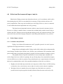
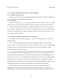
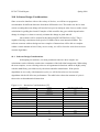
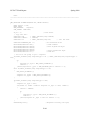
10.1 Software Design Considerations
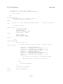
In designing our software, our most prominent concern is how complex our
calculations can be within the certain time constraints of the individual components. When using
the term complex, we are referring to the use of trigonometric functions which are highly costly
with the math library provided to us by the microcontroller manufacturer. If the precise
algorithms are too costly with instruction cycles, we will be forced to use less accurate
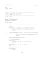
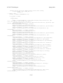
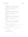
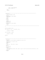
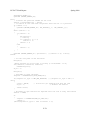
algorithms which will affect our performance. The table below shows the amount of cycles it
takes to do each mathematical instruction.
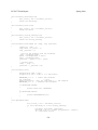
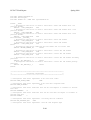
Figure 10.1.1 – Instruction Cost Breakdown [27]
Function Group
Basic Floating Point
Trigonometric and Hyperbolic
Function
Performance (cycles) 1,2,3,4
addition
122
subtraction
124
multiplication
109
division
361
remainder
385
acos
478
asin
363
atan
696
atan2
3206
cos
3249
sin
2238
38
ECE 477 Final Report
Logarithmic and Exponential
Spring 2009
tan
2460
cosh
1049
sinh
525
tanh
338
exp
530
frexp
39
ldexp
44
log
2889
log10
3007
pow
2134
sqrt
493
ceil
94
floor
51
Absolute Value Function
fabs
6
Modular Arithmetic Functions
modf
151
fmod
129
Power Function
Rounding Functions
1. Results are based on using the dsPIC30F MPLAB C30 Compiler (SW006012) version 1.20.
2. Maximum “Memory Usage” when all functions in the library are loaded. Most applications will use less.
3. All performance statistics represented here are for 32-bit IEEE754 floating-point input and output data types.
4. Performance (in instruction cycles) listed here represent an average number of instruction cycles required to
perform the floating-point operation.
There are two specific areas in FlySpy that we foresee having complex, expensive
code. The accelerometer that we are reading on the ATD channels, will give us the reading of
acceleration over the x, y, and z axis. Given just these individual components, we will have to
constantly calculate the magnitude of the axis to see if we are just reading gravitation pull. This
causes for costly the costly square root function, which is not really a big concern. On the other
hand, when calculating the actual pitch and roll values at that instantaneous moment with the
accelerometer, we will need to use the square root and the atan function. As seen in the table, the
atan function will function cost about 696 performance cycles. If clocking at 32 MHz, we have
640,000 cycles available between samples. An alternative to actually using the atan function
would be to compose a look up table that references the actual values of the adc channel to an
angle value. Although this may take a lot of memory, it may prove to be quite helpful in terms of
39
ECE 477 Final Report
Spring 2009
timing if the atan function cannot execute within the about of time that we propose to refresh the
accelerometer data.
The major algorithm that we are taking into consideration is the algorithms that we use
to calculate distance and correct heading from the GPS data. Given that the gps data is basically
represented in degrees, if we want to be precise with our calculations, it will take several
occurrences of trigonometric functions to derive a bearing and distances from two points that are
very precise. We have seen that there are scaled down versions of these algorithms but they do
show that they affect accuracy largely over a certain amount of distance. [28].
Given the fact that we are using various devices, we find ourselves having to model
our software design in a fashion to accommodate for accurate, up to date data from each of these
components while they require different timing subroutines. The GPS module that we are using,
the FV-M8 [4], works at 5 Hz. On the other hand, the IDG300 two-axis gyro [5] will require us
to sample its data faster, around 50 Hz, in order to retrieve accurate data. We view these items as
the two pacesetting products in our design. Therefore we will have to use timer interrupts to
update GPS data and also a faster timer interrupt to sum the change in rotation for the gyro data.
The basic operational logic of the autopilot unit is as flowcharted in Appendix A.
Although shown in a direct format, some procedures will be done iteratively more than other
portions. All procedures of basic operation past initialization will be interrupt driven to assert
that we have clean and up to date data.
The variables that hold the current GPS and orientation information will be stored as
global variable, therefore accessible to all functions. This brings coherence into play but we will
use timing to assert that there is not simultaneous use instead of using locks. Since there will not
be that much program code or memory storage in comparison to the 256Kb series of
microcontrollers that we are using, we will be fine using the default mapping of program
memory for the stack, heap, and program memory. This is displayed in detail in Appendix C.
The PIC24FJ256GA110 is an 100-pin device and we will use the following ports for
interfacing to different devices as listed:
Device Ports
Interface Type
Accelerometer Axes
ATD AN5-3
Range Finder
ATD AN2
40
ECE 477 Final Report
Spring 2009
Gyro Axes
ATD AN1-0
Barometer
SPI0
SD Card
SPI2
GPS Module
SPI3
ICD
I2C
Serial Port
UART
10.2 Software Design Narrative
File Name
Description
Main.c
Used to initialize all micro-controller ports and modules, thereafter it start the
(written in
timer on all interrupts and remain in an empty infinite loop throughout the rest
pseudo-code)
of the operation
ADC.c/ADC.h
This module consists of functions to operate all analog to digital functions.
(written and
This reduces t has control of all the channels, has multiple functions and can
tested)
read all channels base on the channel number
Timer.c
Initializes all time interrupts for all general operation. Has multiple clocks for
(written and not
different timers ( Ex: 5 Hz for GPS, 50Hz for orientation calculations.)
tested)
GPS.c
This module consists of functions to retrieve GPS data from the GPS receiver.
(written in
Also functions to calculate difference in baring and distance
pseudo-code)
Camera.c
Module consists of simple functions that control the operations of a camera.
(written in
Simply turning the camera on, flash, a picture signal and placing the camera
pseudo-code)
back to the off state
Filesystem.c
Module consists formatting for i/o into the auto pilot programs. Uses
(written in
microchips filesystem library to read and write from the non-volatile memory
pseudo-code)
Control.c
Has functions which set the PMW control signals to the aircraft control
41
ECE 477 Final Report
(written in
Spring 2009
surfaces.
pseudo-code)
Sensors.c
Module consists of algorithm that will be used to fuse the accelerometer and
(written in
gyro data to successful obtain the planes orientation. Also, it will retrieve and
pseudo-code)
use data from the barometer and range finder, setting the global variables for
other modules to make uses.
Config.c
Module simply sets the peripheral pin select and tri-state i/o of 100 pin
(written and not
microchip
tested)
Transmitter.c
Module uses input capture to clock manual users control signals from the
(written in
receiver unit
pseudo-code)
10.3 Summary
In designing the software for FlySpy, timing is the most critical issue. Besides the testing that we
can do in to see if any algorithm has given us the correct response, we still will have to alter our
workflow to accommodate the response rate needed for a stabile flight. We believe that we have
come up with a solution that will yet and still pass the test of updating in a timely fashion with
the required peripherals.
42
ECE 477 Final Report
Spring 2009
11.0 Version 2 Changes
Put parts directly onto the PCB instead of on breakout boards (examples: SD card,
all of our sensors). This would make our design more manufacturable and allow us
to compact the PCB more.
Find PCB space to include the ICD 2 (debug) header and RS-232 serial port
instead of using external adapter boards.
Instead of using the accelerometer, which is affected by the plane’s motion, to
estimate the direction of “down”, we could use a non-inertial device, such as a
magnetometer, to correct for errors in the inertial system’s orientation estimates.
Power the multiplexer directly off the 5V power rail, which eliminates its
dependence on the proper operation of the 3.3V buck converter.
Incorporate two-way wireless communication.
43
ECE 477 Final Report
Spring 2009
12.0 Summary and Conclusions
As far as electrical engineering work goes, the FlySpy project has been a success. There
were no hardware problems, and there are no known logic bugs in the software. As of the writing
of this report, the software only lacks proper parameter tuning, and if that can be completed, all
five PSSCs will be completed by the end of the semester.
The project has been very educational, providing an opportunity to work with all manner
of interesting hardware (inertial sensors, GPS, microcontrollers) in a real-world application
setting. The team gained significant real-world design and engineering skills, particularly with
respect to navigating the jungle of parts available and in doing research to get a problem solved
expediently. The team also learned to work independently; the TAs, while nearly always helpful,
did not have all the answers, and the team had to learn to deal with this.
FlySpy was certainly the “something cool” that we went into engineering to create.
Although we didn’t quite complete it, we have made great strides in our understanding of the
engineering process in the real world as a result of working on it.
44
ECE 477 Final Report
Spring 2009
13.0 References
[1] Microchip “PIC24FJ128GA106 Detail Page” [Online]
Available:http://www.microchip.com/wwwproducts/Devices.aspx?dDocName=en532133.
[Accessed: February 06, 09].
[2] Freescale “S12HZ Product Summary Page” [Online]
Available:http://www.freescale.com/webapp/sps/site/prod_summary.jsp?code=S12HZ&fsr
ch=1. [Accessed: February 06, 09]
[3] Multiplex “Easy Star Model Kit” 2007 [Online]
Available: http://www.multiplexusa.com/models/kits/easy_star.php
[Accessed: January 9, 09]
[4] Multiplex “Easy Glider Pro Kit” 2007 [Online]
Available: http://www.multiplexusa.com/models/kits/easy_glider_pro.php
[Accessed: January 9, 09]
[5] Chris Anderson “Review: Multiplex EasyGlider Pro for UAV use”, December 4, 2008
[Online]
Available: http://www.diydrones.com/profiles/blogs/review-multiplex-easyglider
[Accessed: December 26, 2006]
[6] Chris Parker “Virtual Reality: 3DOF Tracker”, August 13, 2007 [Online]
Available: http://www.virtualreality.net.au/3DOF_Tracker
[Accessed: January 14, 2009]
[7] Randal W. Beard, Walter H. Johnson, Reed Christiansen, Joshua M. Hintze, Timothy W.
MeLain, “Programmable autopilot system for autonomous flight of unmanned aerial
vehicles,” U.S. Patent No. 7302316, November 27, 2007
[8] Gregory E. Dockter, Donald G. Caldwell, Jason Graham, “Precision Approach Control,”
U.S. Patent Application No. 2008/0071431, March 20, 2008
[9] Douglas G. Nelson, “Anti-hijacking system operable in emergencies to deactivate on-board
flight controls and remotely pilot aircraft utilizing autopilot,” U.S. Patent Application No.
2004/0079837, April 29, 2004
[10] “MIL-HDBK-217F Military Handbook: Reliability Prediction of Electronic Equipment,”
[Online document], 1991 Dec 2, [cited 2009 Apr 9], Available HTTP:
https://engineering.purdue.edu/ece477/Homework/CommonRefs/Mil-Hdbk-217F.pdf
[11] “PIC24FJ256GA110 Family Data Sheet,” [Online document], 2008 Jan 2, [cited 2009 Apr
9], Available HTTP: http://ww1.microchip.com/downloads/en/DeviceDoc/39905b.pdf
45
ECE 477 Final Report
Spring 2009
[12] “PI3V512 Low On-Resistance, 3.3V Wideband/Video Switch 5-Port, 2:1 Mux/DeMux,”
[Online document], 2004 Nov 1, [cited 2009 Apr 9], Available HTTP:
http://www.pericom.com/pdf/datasheets/PI3V512.pdf
[13] “LTC1174/LTC1174-3.3/LTC1174-5 High Efficiency Step-Down and Inverting DC/DC
Converter,” [Online document], 1994 (Rev E), [cited 2009 Apr 9], Available HTTP:
http://www.linear.com/pc/downloadDocument.do?navId=H0,C1,C1003,C1042,C1033,P139
2,D2997
[14] “Polystyrene,” Wikipedia, 2009. [Online]. Available:
http://en.wikipedia.org/w/index.php?title=Polystyrene&oldid=283740881#Disposal_and_e
nvironmental_issues .
[15] “Restriction of Hazardous Substances Directive”, Wikipedia, 2009. [Online]. Available:
http://en.wikipedia.org/w/index.php?title=Restriction_of_Hazardous_Substances_Directive
&oldid=284259028#Effect_on_reliability .
[16] Micro Pilot, “MicroPilot - Products - MP2028g,” [Online Document], [cited 1 November
2008]. [Online]. Available: http://www.micropilot.com/products-mp2028g.htm
[17] Procerus Technology, “Procerus Technology Kestrel Autopilot,” [Online Document], [cited
1 October 2008], http://www.procerusuav.com/productsKestrelAutopilot.php
[18] Microchip Technology Inc., “PIC24FJ256GA110 Family Data Sheet”, February 2008.
[Online]. Available: http://ww1.microchip.com/downloads/en/DeviceDoc/39905b.pdf .
[Accessed: Feb. 17, 2009].
[19] Microchip Technology Inc., “Microchip ICD-2 datasheet”, 2005. [Online]. Available:
http://www.farnell.com/datasheets/53561.pdf. [Accessed: Feb. 17, 2009].
[20] Maxbotix, “Maxbotix LV-MaxSonar-EZ1 High Performance Sonar Rangefinder”, July
2007. [Online]. Available: http://www.maxbotix.com/uploads/LV-MaxSonar-EZ1Datasheet.pdf. [Accessed: Feb. 17, 2009].
[21] M. Glenewinkel, “Motorola App Note,” [Online document], 1995, [cited 2009 Feb 27],
Available HTTP:
https://engineering.purdue.edu/ece477/Homework/CommonRefs/AN1259.pdf
[22] “LTC1174/LTC1174-3.3/LTC1174-5 High Efficiency Step-Down and Inverting DC/DC
Converter,” [Online document], 1994 (Rev E), [cited 2009 Feb 27], Available HTTP:
http://www.linear.com/pc/downloadDocument.do?navId=H0,C1,C1003,C1042,C1033,P139
2,D2997
[23] “SparkFun Electronics – Gyro Breakout Board – Dual Axis IDG300,” [Online document],
[cited 2009 Feb 27], Available HTTP:
http://www.sparkfun.com/commerce/product_info.php?products_id=698
46
ECE 477 Final Report
Spring 2009
[24] “ANTARIS 4 GPS Modules System Integration Manual (SIM),” [Online document], (Rev
A1), [cited 2009 Feb 27], Available HTTP:
http://www.u-blox.com/customersupport/gps.g4/ANTARIS4_Modules_SIM(GPS.G4-MS405007).pdf
[25] Microchip “PIC24FJ128GA106 Detail Page” [Online]
Available:http://www.microchip.com/wwwproducts/Devices.aspx?dDocName=en532133.
[Accessed: February 06, 09].
[26] Microchip “PIC24 MCU / dsPIC DSC Math Library”
Available:
http://www.microchip.com/stellent/idcplg?IdcService=SS_GET_PAGE&nodeId=2680&dD
ocNam=en022432
[Accessed: March 19, 09].
[27] DIYDrones “New ArduPilot Pocket Navigation Algorithm”
Available: http://diydrones.com/profiles/blogs/new-ardupilot-pocket
[Accessed: March 24, 09].
[28] Sparkfun “FV-M8 GPS Spec”
Available: http://www.sparkfun.com/datasheets/GPS/FV-M8_Spec.pdf
[Accessed: March 27,09]
47
ECE 477 Final Report
Spring 2009
Appendix A: Individual Contributions
A.1 Contributions of Heather Barrett:
Hardware Design
I was heavily involved in the hardware design. I did about 95% of the work on the first
schematic revision, assisted by Jeremy and William’s research into the microcontroller
peripheral pin select feature along with the function of the PWM channels, A/D channels, and
SPI and SCI interfaces. I was also heavily involved with the component selection and
acquisition. I was heavily involved in the PCB footprint creation, planning, component
placement, wiring, and component verification of the PCB.
Documentation
I put together the senior design report by myself, worked with William on the final
report and worked with Daeho on the user manual.
Construction
I did some of the soldering on the PCB and soldered some connectors.
Miscellaneous
I helped with top level planning in the early stages of the project.
A.2 Contributions of William Ehlhardt:
With respect to the design project itself, I primarily worked on the hardware design. I
did a lot of the work in nailing down the overall structure of the hardware, designing the flow of
signals from system to system. I worked out which microchip peripherals we were using and
how they connected to the sensors and other hardware. I selected the microcontroller based on
our peripheral usage, as well as other part selection; I was the one who decided to change GPS
modules instead of trying to get the GPS antenna signal routed. I did the mapping of functions to
pins on the microcontroller and the subsequent pin function changes required to make routing
easier.
A-1
ECE 477 Final Report
Spring 2009
I did the bulk of the work on the PCB layout and the subsequent schematic redesigns
made to facilitate routing. The PCB was my single most significant functional contribution to the
project and took me the better part of two weeks.
Once the PCB came back, I helped with the hardware assembly, although I had others
do some of the harder soldering work. I assembled the 3.3V power supply and babysat it through
several hours of burn-in under load. I validated the signal conditioning for the gear switch
(autopilot/manual) control, catching a capacitor value mistake in the process. I then validated the
whole autopilot/manual multiplexing system and confirmed its correct operation.
While Jeremy did the bulk of the software development, I helped significantly on it. I
wrote the SPI-based driver for the barometer myself. I also did the tedious work of creating the
peripheral pin select code that assigns the microcontroller peripherals to physical pins (although I
later discovered that there was an automation tool to do all that easily). I managed to track down
several minor and a few major bugs that were tripping Jeremy up.
Heather and I did the compilation of the homeworks into the final report submission
materials, along with a lot of the editing thereof.
A.3 Contributions of Daeho Hong:
My major part in this project was to implement SD card interface and flight logging
functions. First I spent a few weeks to research on how SD card works and FAT file system
works because I expected that I have to write the entire file header and generate control signals
for the SD card. I also researched on the SD card circuitry which was simple and it did not take a
lot of time. SD card breakout board was purchased and it helped a lot.
After our microcontroller was selected, I found out that there were file I/O library for
PIC microcontroller on microchip.com which is the vendor of our microcontroller. It offered the
most of the SD card interface and file I/O functions and some optional functions could be
enabled by our needs. I enabled fprintf function which was initially disabled to save resources of
the microchip. I wrote flight logging functions to write the log in XML script so that it can be
displayed with a certain scheme but it was not suitable for our situation so Jeremy changed to
just text log.
After the flight logging is done, I wanted to help Jeremy figuring out the flight
controls but Jeremy was too ahead of me to catch up his pace and I decided to work on other
A-2
ECE 477 Final Report
Spring 2009
miscellaneous part that can help our team. Therefore, I spent time on preparing the user-manual
and poster. For user manual, the installation process, user guide, and trouble-shooting were
written. It was very straight forward and I felt that the manual control mode and flight logging
functions were the most important part that can help the user to solve the problem when they
encounter any unfavorable circumstance.
For the poster, I took the image of our plane and edited it with Photoshop so that it can
get along with the aerial photograph of Purdue Memorial Mall. I paid more attention on the
graphic to make it interesting for the audience and revised it to make sure that it contains
necessary information. The size of the poster was limited and it was difficult to put everything in
the poster.
A.4 Contributions of Jeremy Tillman:
As the team leader for FlySpy, I was in charge of researching existing methods of
controlling a RC Airplane autonomously. Since no one on the team, including myself, had no
previous experience of flying RC Airplanes, I successfully sought out advice and experienced
pilots to support the group with piloting and controls skills. Once enough contacts and
information were acquired, I focused more on the components that the airplane would operate off
of and its general logic of operation. In doing so, I selected the components that would be
included in our design, as well as the aircraft that we would modify. I researched Inertial
Measurement Units and what devices would be needed in building our own to given us adequate
information about our airplane’s orientation and position.
I acquired an unused camera from a personal friend. Thereafter, I disassembled it to
gain access to pins that would enable the microcontroller to power on and off, as well as take
picture with. I was very much involved in the hardware block diagram and loosely involved with
the actual schematic, only lending a hand where previous knowledge of interfacing or deep skills
were not needed. Once the plane was purchase, I assembled it to its stock entirety. I also setup
flight dates with our experienced pilot to flight test the plane, noting the power of the engine and
flight traits of the airframe.
Once the devices were purchased for the PCB, I learned to solder small port
appropriately, as our microcontroller had a small pitch and a large amount of pins. I used a
soldered a practice microcontroller to the breakout board and started developing a small amount
A-3
ECE 477 Final Report
Spring 2009
of code before the actual board had arrived. I also soldered the microcontroller and multiple
breakout devices to the PCB. Thereafter, I made cables that interfaced with the PC and off board
peripherals.
I was in charge of the entire autopilot program aside from bare level microcontrollerdevice interfacing. I asserted that the plane was retrieving correct information from the off chip
devices and use them to determine the control of the planes surfaces as well as throttle. Once a
reasonable amount of the program was written, I found material and methods to package the
PCB board into the cockpit as well as mount the camera and range finder to the bottom. When
the packaging was complete, I setup times with experienced pilots to test the autopilot algorithm.
A-4
ECE 477 Final Report
Spring 2009
Appendix B: Packaging
5”
1.5”
Figure B-1: Approximate placement of PCB within fuselage (top view)
1”
5”
Figure B-2: Overall packaging sketch
B-1
ECE 477 Final Report
Spring 2009
Appendix C: Schematic
C-1
ECE 477 Final Report
Spring 2009
Appendix D: PCB Layout Top and Bottom Copper
Fig D-1: PCB Top Layer
D-1
ECE 477 Final Report
Spring 2009
Fig D-2: PCB Bottom Layer
D-2
ECE 477 Final Report
Spring 2009
Appendix E: Parts List Spreadsheet
Vendor
MicroChip
Advantage Hobby
Advantage Hobby
Advantage Hobby
Advantage Hobby
Advantage Hobby
SparkFun
SparkFun
SparkFun
SparkFun
Ublox
Jeremy Tillman
Jeremy Tillman
Manufacturer
MicroChip
Multiplex
Multiplex
Multiplex
Multiplex
Multiplex
InvenSense
VIT Tech.
Analog Devices
Maxbotix
Ublox
Nikon
Secure Digital
Part No.
Description
PIC24FJ128GA106
MPU214226
MPUM998226
MPUM993226
SPM6600
FPWEVOLITE25002S
SEN-00698
SCP1000
ADXL330
LV-EZ1
16-bit Microcontroller
Easy Glider Pro Kit
Easy Glider Pro Servo Pack
Easy Glider Pro Power Pack
DX6i 6 Channel Spread Spectrum Rx/Tx
Li-Po 7.4V 2500mAh Battery
Dual Axis Gyro
Mems Barometric Pressure Sensor
Triple Axis Accelerometer
Ultrasonic Range Finder
Programmable GPS Module
LEA-4P
Coolpix s7
1GBSD
Camera
SD Card
Unit Cost
Qt
y
Total Cost
$4.90
$109.99
$77.89
$145.89
$199.99
$49.99
$74.95
$54.95
$34.95
$24.95
$99.99
1
1
1
1
1
1
1
1
1
1
1
$4.90
$109.99
$77.99
$145.89
$199.99
$49.99
$74.95
$54.95
$34.95
$24.95
$99.99
$0
$0
1
1
$0
$0
TOTAL
E-1
$878.54
ECE 477 Final Report
Spring 2009
Appendix F: Software Listing
/****************************************************************************
* FlySpy v0.c
* Authors: Jeremy Tillman, William Ehlhardt
* Project: FlySpy
*
ECE477, Team 12, Spring 2009
****************************************************************************/
#include "FlySpy.h"
_CONFIG1( JTAGEN_OFF & GCP_OFF & GWRP_OFF & COE_OFF & FWDTEN_OFF & ICS_PGx2)
_CONFIG2( FCKSM_CSDCMD & OSCIOFNC_OFF & POSCMOD_NONE & FNOSC_FRCPLL)
extern
extern
extern
extern
extern
extern
extern
extern
GPSINFO CurrentGPS;
WAYPOINT wayPoints[MAXWAYPOINTS];
TAKEOFFLANDING StartEndPoint;
SENSORDATA sensorInfo;
int wayPointCount;
int SecondFlag;
int TimerFlag;
int TimerCount;
int main(void)
{
float man_l_ail, man_r_ail, man_throttle, man_elev, man_rudder;
unlockIO();
CLKDIV = 0x3000; // Changes Oscillator Postscalar to 1:1
ioMap();
//Set micro pin directions and peripherals pin selects
lockIO();
//Locks port pin directions
initgps();
//Initializes communication to the GPS through UART and
configures its message types
initCamera();
//Initializes Camera Outputs
gpserial_init();
//Initializes the communication to the RS-232
#ifdef GPS_PASSTHROUGH
#warning Compiling for GPS passthrough mode.
printf("GPS Passthrough mode go!\r\n");
gps_passthrough();
#endif
initio();
//Initializes SD Communication and Reads in Flight
Information
initSensors();
//Initializes the Sensor structure and zeros sensor
algorithms
initSurfaces();
initADC();
//Initializes the Analog to digital module
barometer_init(); //Intitializes and starts communication with the SPC-1000
initTimer();
//Initializes and starts all Timer
initpwm();
//Initializes Input Capture of the Receiver PWM and Output
Compare of PWM to Airplane Control Surfaces
printf("Please Wait to Aquire GPS Signal\r\n");
do
{
retrieveGpsData();
}while(!CurrentGPS.Signal);
F-1
ECE 477 Final Report
Spring 2009
printf("GPS Signal Aquired!\r\n");
#ifdef MANUAL_ONLY_MODE
printf("Manual only mode\r\n");
FSFILE *fptr;
int length = 0;
char logBuffer[2000];
int lastState = 1;
int val;
int count = 0;
int length_check;
__delay32(32000000);
fptr = FSfopen("LOG.TXT", "w");
if ( fptr == NULL )
{
printf("Error in Creating LOG.TXT: %d\r\n", FSerror());
while(1);
}
FSfprintf(fptr, "Time, Latitude, Longitude, Speed, Heading, Pitch,
Roll, Altitude, Clearing, Throttle, L-Aileron, R-Aileron, Elevator, Rudder, Gyro Pitch
Volt, Gyro Roll Volt, AccelG X, AccelG Y, AccelG Z, Variance\r\n");
FSfclose(fptr);
while(1)
{
val = CTRL_SW;
if ( lastState != val )
{
if ( val == 0)
{
fptr = FSfopen("LOG.TXT", "a");
if (fptr == NULL)
{
printf("Error in FSfopen of
LOG.TXT: %d\r\n", FSerror());
while(1);
}
}
else
{
if ( length > 0)
{
length_check =
FSfwrite(logBuffer,1,length, fptr);
if(length
{
!=length_check)
FSfclose(fptr);
printf("Error in
FSfwrite: %d\r\n", FSerror());
while(1);
}
length = 0;
FSfclose(fptr);
}
}
lastState = val;
}
retrieveGpsData();
F-2
ECE 477 Final Report
Spring 2009
if (TimerFlag == 1)
{
if (lastState == 0 )
{
read_PWM_IN(&man_l_ail, &man_r_ail,
&man_throttle, &man_elev, &man_rudder);
sensorInfo.inuse = 1;
length +=
sprintf(&logBuffer[length],"%2d:%2d:%2d.%3d.%1d, %8.6f, %9.6f, %5.2f, %6.3f, %4.3f,
%4.3f, %4.3f, %4.3f, %4.3f, %4.3f, %4.3f, %4.3f, %4.3f, %4.3f, %4.3f, %4.3f, %4.3f,
%4.3f, %4.3f\r\n", CurrentGPS.Hour, CurrentGPS.Minute, CurrentGPS.Second,
CurrentGPS.Mils, TimerCount, CurrentGPS.Latitude, CurrentGPS.Longitude,
CurrentGPS.Heading, CurrentGPS.Speed, sensorInfo.Pitch, sensorInfo.Roll,
sensorInfo.Altitude, sensorInfo.Clearing, (double) man_throttle, (double) man_l_ail,
(double) man_r_ail, (double) man_elev,(double) man_rudder,
sensorInfo.GyroPitchVoltage, sensorInfo.GyroRollVoltage, sensorInfo.Accelerometer_X,
sensorInfo.Accelerometer_Y, sensorInfo.Accelerometer_Z, sensorInfo.MagnitudeVariance);
sensorInfo.inuse = 0;
}
count++;
if ( count > 9 )
{
if ( length > 0)
{
length_check =
FSfwrite(logBuffer,1,length, fptr);
if(length
{
!=length_check)
FSfclose(fptr);
printf("Error in
FSfwrite: %d\r\n", FSerror());
while(1);
}
length = 0;
}
count = 0;
}
TimerFlag = 0;
}
}
#else
double targetBearing;
double targetDistance;
double bearingDifference;
double Pitch;
double Roll;
int wp_index; // Indexs the current waypoint that we are
approaching in the wayPoints array
int lcv;
float auto_l_ail, auto_r_ail, auto_throttle, auto_elev,
auto_rudder;
enableControlSurfaces();
wp_index = 0;
logStart();
if ( StartEndPoint.TakeOff )
{
SecondFlag = 0 ;
lcv = 0;
while( lcv < StartEndPoint.Delay )
F-3
ECE 477 Final Report
Spring 2009
{
__delay32(SYSCLK/2);
lcv++;
}
setSurface(.5,THROTTLE);
setPitch(20);
setRoll(0);
while(StartEndPoint.TakeOff_Altitude - sensorInfo.Altitude
> 20);
}
setSurface(.5, THROTTLE);
while (wp_index < wayPointCount)
{
retrieveGpsData(); //Retrieves Current GPS Data
calculatePath(CurrentGPS.Latitude, CurrentGPS.Longitude,
wayPoints[wp_index].Latitude, wayPoints[wp_index].Longitude, &targetDistance,
&targetBearing);
if (targetDistance < .020) //if Distance is less than 20
meters
{
if ( wayPoints[wp_index].Picture == 1)
{
setPitch(0);
setRoll(0);
logPicturePoint(&CurrentGPS);
takePicture();
}
wp_index++;
}
else
{
bearingDifference = fmodf(targetBearing CurrentGPS.Heading + 540, 360) - 180;
Roll = bearingDifference * MAX_ROLL / 180;
//
sensorInfo.inuse = 1;
//
if ( sensorInfo.Altitude * 100 - 25 >
wayPoints[wp_index].Altitude )
//
{
//
Pitch = -MAX_PITCH;
//
}
//
else if ( sensorInfo.Altitude * 100 <
wayPoints[wp_index].Altitude - 25 )
//
{
//
Pitch = MAX_PITCH;
//}
//sensorInfo.inuse = 0;
//Equate how much turn should be given at the
time
//Call setOrientation to guide the plane in that
direction
//setRoll(Roll);
//setPitch(Pitch);
setRoll(ROLL_ZERO);
setPitch(PITCH_ZERO);
}
if(SecondFlag == 1)
{
read_PWM_IN(&man_l_ail, &man_r_ail,
&man_throttle, &man_elev, &man_rudder);
read_PWM_OUT(&auto_l_ail, &auto_r_ail,
&auto_throttle, &auto_elev, &auto_rudder);
sensorInfo.inuse = 1;
F-4
ECE 477 Final Report
Spring 2009
logCoord(&wayPoints[wp_index],&CurrentGPS,
targetDistance, targetBearing, sensorInfo.Altitude, sensorInfo.Pitch, sensorInfo.Roll,
sensorInfo.Clearing, auto_throttle, auto_elev, auto_rudder, auto_l_ail, auto_r_ail,
man_throttle, man_elev, man_rudder, man_l_ail, man_r_ail);
//Log information to SD Card
sensorInfo.inuse = 0;
SecondFlag = 0;
}
}
if ( StartEndPoint.Landing )
{
//Go to landing
}
setPitch(PITCH_ZERO);
setRoll(ROLL_ZERO);
setSurface(0,THROTTLE);
#endif
while(1);
return 0;
}
/****************************************************************************
* ADC.c
* Authors: Jeremy Tillman, William Ehlhardt
* Project: FlySpy
*
ECE477, Team 12, Spring 2009
****************************************************************************/
#include "FlySpy.h"
void initADC()
{
AD1PCFGH = 0x0000; //All Ports to analog inputs
AD1PCFGL = 0x0000;
AD1CON1 = 0x00E0; // SSRC<3:0> = 111 implies internal
// counter ends sampling and
starts
// converting.
// in this example AN12 is the input
AD1CSSL = 0;
AD1CON3 = 0x1F02; // Sample time = 31Tad,
// Tad = 2 Tcy
AD1CON2 = 0;
AD1CON1bits.ADON = 1; //turning ADC ON
return;
}
void setADCPort(int portNumber)
{
AD1CHS = portNumber; // Setting the ADC input as the appropriate pin;
}
int retrieveADCVal()
{
F-5
ECE 477 Final Report
Spring 2009
int retVal;
AD1CON1bits.DONE = 0; //Assert that the DONE bit has been cleared from
previous ADC Read
AD1CON1bits.SAMP = 1; // Starting to sample and then will automatically go
into convert
while(!AD1CON1bits.DONE); // Wait for conversion to finish
retVal = ADC1BUF0;
return(retVal);
}
int sampleADCPort(int portNumber)
{
int retVal;
setADCPort(portNumber);
retVal = retrieveADCVal();
//Set the analog port to sample
//Retrieve port value
return (retVal);
}
/****************************************************************************
* ADC.h
* Authors: Jeremy Tillman, William Ehlhardt
* Project: FlySpy
*
ECE477, Team 12, Spring 2009
****************************************************************************/
void initADC();
void setADCPort(int);
int retrieveADCVal();
int sampleADCPort(int);
/****************************************************************************
* barometer.c
* Authors: Jeremy Tillman, William Ehlhardt
* Project: FlySpy
*
ECE477, Team 12, Spring 2009
****************************************************************************/
#include "FlySpy.h"
extern SENSORDATA sensorInfo;
#define
#define
#define
#define
MYSPISTAT
MYSPICON1
MYSPICON2
MYSPIBUF
SPI1STATbits
SPI1CON1bits
SPI1CON2
SPI1BUF
signed int temp = 0;
long pressure = 0;
float Altitude = 0;
static unsigned char spi_comm(unsigned char send)
{
unsigned char reply = 0;
MYSPISTAT.SPIROV = 0;
// clear Mr. Overflow Bit
MYSPIBUF = send;
// Initiate the transfer
while (MYSPISTAT.SPITBF) ; // And wait for its completion
while (!MYSPISTAT.SPIRBF) ; // Wait for a byte
reply = (MYSPIBUF & 0xFF);
F-6
ECE 477 Final Report
Spring 2009
//printf("0x%02x ", (int) reply);
return reply;
// And feed it back
}
static void writereg8(unsigned char addr, unsigned char value)
{
// Convert the address into the "write to this address"
// command to be sent over the SPI bus
addr = (addr << 2) | 0b00000010;
BAROMETER_CS = 0; // Select the barometer
spi_comm(addr);
// Throw the data onto (under?) the bus
spi_comm(value);
BAROMETER_CS = 1; // Deselect the barometer
}
/* I don't think there are any 16-bit writable registers.
-William */
#if 0
static void writereg16(unsigned char addr, unsigned int value)
{
// Convert the address into the "write to this address"
// command to be sent over the SPI bus
addr = (addr << 2) | 0b00000010;
BAROMETER_CS = 0; // Select the barometer
spi_comm(addr);
// Throw the data onto (under?) the bus
spi_comm((value >> 8) & 0xFF);
// Send the high byte first,
spi_comm(value & 0xFF);
// and then the low byte
BAROMETER_CS = 1; // Deselect the barometer
}
#endif
static unsigned char readreg8(unsigned char addr)
{
unsigned char ret = 0;
// Convert the address into the "read from this address"
// command to be sent over the SPI bus
addr = (addr << 2) & 0b11111100;
BAROMETER_CS = 0;
spi_comm(addr);
ret = spi_comm(0x00);
BAROMETER_CS = 1;
// Select the barometer
// Send a "read" command
// Read back the response
// Deselect the barometer
return ret;
}
static unsigned int readreg16(unsigned char addr)
{
unsigned int high = 0, low = 0;
// Convert the address into the "read from this address"
// command to be sent over the SPI bus
addr = (addr << 2) & 0b11111100;
BAROMETER_CS = 0;
spi_comm(addr);
high = spi_comm(0x00);
low = spi_comm(0x00);
BAROMETER_CS = 1;
// Select the barometer
// Send a "read" command
// Read back the high byte
// Read back the low byte
// Deselect the barometer
return (high << 8) | low;
}
F-7
ECE 477 Final Report
Spring 2009
void barometer_init(void)
{
/**** Set up the SPI interface ****/
BAROMETER_CS = 1; // deselect the barometer
MYSPISTAT.SPIEN = 0;
// turn off the module
MYSPICON1.DISSCK
MYSPICON1.DISSDO
MYSPICON1.MODE16
MYSPICON1.SMP
MYSPICON1.CKE
= 0;
= 0;
= 0;
// enable PIC-sourced clock
// SDO pin controlled by module
// Byte-width communications
= 0;
// Sample phase (TODO: check this?)
= 1;
// Latch out new data on the FALLING
// clock edge; the
barometer latches
// it in on the
RISING edge.
MYSPICON1.SSEN
MYSPICON1.CKP
MYSPICON1.MSTEN
= 0;
= 1;
// Don't use SS1 pin
= 0;
// Clock idles on LOW
// Master mode
/* Set the clock output to 125kHz */
(SYSCLK == 8000000)
MYSPICON1.PPRE
= 1;
// 1:16 primary prescale
#elif (SYSCLK == 32000000)
MYSPICON1.PPRE
= 0;
// 1:64 primary prescale
#else
#error Unsupported clock frequency!
#endif
MYSPICON1.SPRE
= (8 - 2);
// 1:2 secondary prescale
#if
MYSPICON2 = 0;
// Don't use any framed mode stuff
// TODO: config to monitor transmit/receive status?
MYSPISTAT.SPIEN = 1;
// flip that bad boy back on
while (barometer_startup_running())
{
__delay32(8000000);
printf("BaroBoot\r\n");
}
/*
Order the barometer to commence acquisition in high-speed
continuous mode */
writereg8(0x03, 0x09);
}
baro_status_t barometer_status(void)
{
unsigned char status = 0;
baro_status_t res = {0,0,0};
// Read in the device status
status = readreg8(0x07);
//printf("0x%02x ", (int) status);
// Mash together the output structure
res.dataready
= !!(status & 0b00100000);
res.error
= !!(status & 0b00010000);
res.startup_running
= !!(status & 0b00000001);
return res;
}
F-8
ECE 477 Final Report
Spring 2009
char barometer_dataready(void)
{
baro_status_t res = barometer_status();
return res.dataready;
}
char barometer_error(void)
{
baro_status_t res = barometer_status();
return res.error;
}
char barometer_startup_running(void)
{
baro_status_t res = barometer_status();
return res.startup_running;
}
void barometer_read(signed int *temp, long *pressure)
{
signed int _temp = 0;
long presh = 0, presl = 0;
long _pressure = 0;
// Pull in the readings from the barometer
_temp = readreg16(0x21);
presh = readreg8(0x1F) & 0b111;
presl = readreg16(0x20);
_pressure = (presh << 16) | presl;
// Convert units
*temp = _temp / 2;
*pressure = (_pressure >>2);
}
void barometer_test()
{
unsigned char addr = 0x07;
unsigned char cmd = (addr << 2) & 0b11111100;
BAROMETER_CS = 0; // Select the barometer
spi_comm(cmd);
// Call
printf("%02x\r\n", (int) spi_comm(0x00)); // and response
BAROMETER_CS = 1; // Deselect the barometer
if (MYSPISTAT.SPIRBF)
{
printf("%02x\r\n", MYSPIBUF);
}
if (MYSPISTAT.SPIROV)
{
printf("LOLOVERFLOW\r\n");
}
}
void updateAltitude()
{
baro_status_t stat = barometer_status();
if (stat.dataready && (!stat.startup_running))
{
barometer_read(&temp, &pressure);
Altitude = 44.33 - 4.9465* pow(pressure, .190263);
if (!sensorInfo.inuse)
F-9
ECE 477 Final Report
Spring 2009
sensorInfo.Altitude = Altitude;
}
}
/****************************************************************************
* barometer.h
* Authors: Jeremy Tillman, William Ehlhardt
* Project: FlySpy
*
ECE477, Team 12, Spring 2009
****************************************************************************/
#ifndef __BAROMETER_H
#define __BAROMETER_H
/***** API OVERVIEW *****/
/*
This file is a driver for the SCP1000 barometer over SPI#1.
To use the barometer,
1. Call barometer_init() to set it up to acquire data.
2. Don't read data until barometer_status reports that startup
is complete.
3. Poll barometer_status() every 10-20ms [1] to see if there
is data ready to be bussed in.
4. If so, call barometer_read() to get that data.
[1]
In high-speed acquisition mode, you have a 25ms window
between the barometer having data ready and the time that
it starts to acquire a new value and trashes its data
buffer. barometer_status() reports when new data is ready.
*/
void barometer_init(void);
typedef struct _baro_status_t
{
// Is there data ready to be read in?
unsigned dataready:1;
/* Indicates whether the last "data ready" timed out before
the micro serviced it.
Should this be the case, the next value to be returned
by barometer_read will be garbage; however, the read
will clear the error */
unsigned error:1;
// Startup procedure running?
unsigned startup_running:1;
}
baro_status_t;
baro_status_t barometer_status(void);
char barometer_dataready(void);
char barometer_error(void);
char barometer_startup_running(void);
/*
Returns the barometer's measured temperature in TENTHS of degC,
and the pressure in TENTHS of Pascals.
Notice that there is a chance this could return garbage;
see the "error" bit documentation above.
It would also be a poor plan to call this if the dataready
status bit is not set.
*/
void barometer_read(signed int *temp, long *pressure);
F-10
ECE 477 Final Report
Spring 2009
void barometer_test();
void updateAltitude();
#endif
/****************************************************************************
* camera.c
* Authors: Jeremy Tillman, William Ehlhardt
* Project: FlySpy
*
ECE477, Team 12, Spring 2009
****************************************************************************/
#include "FlySpy.h"
void initCamera()
{
/* Pull both control outputs HIGH on bootup */
CAM_SHUTTER = 1;
CAM_POWER = 1;
}
int changePowerMode(int mode)
{
// If the camera is not in the desired power state...
if(CAM_POW_FB != mode)
{
// "Close" the power switch by pulling LOW
CAM_POWER = 0;
// Keep it closed until the power state changes to the
// desired state, as reported by the feedback
if (CAM_POW_FB != mode)
{
__delay32(1000000); //Only wait for a specific amount of
time so plane can control itself again
}
}
// We have reached the desired mode, so flip that pin back
// on up to "high"
CAM_POWER = 1;
__delay32(1000000);
if (CAM_POW_FB != mode)
return 0;
return 1;
}
int powerOnCamera()
{
return (changePowerMode(1));
}
int powerOffCamera()
{
return ( changePowerMode(0) );
}
int takePicture()
{
int status;
status = powerOnCamera();
if ( status == 1)
{
F-11
ECE 477 Final Report
Spring 2009
// "Close" the shutter switch by pulling it LOW
CAM_SHUTTER = 0;
__delay32(1000000);//Wait for delayed amount of time for camera to
finish shot
// Pull the shutter switch back HIGH
CAM_SHUTTER = 1;
__delay32(128000000);
status = powerOffCamera();
}
return ( status );
}
/****************************************************************************
* camera.h
* Authors: Jeremy Tillman, William Ehlhardt
* Project: FlySpy
*
ECE477, Team 12, Spring 2009
****************************************************************************/
void initCamera(void);
int takePicture(void);
/****************************************************************************
* Compiler.h
* Authors: Jeremy Tillman, William Ehlhardt
* Project: FlySpy
*
ECE477, Team 12, Spring 2009
****************************************************************************/
/*********************************************************************
*
*
Compiler and hardware specific definitions
*
*********************************************************************
* FileName:
Compiler.h
* Dependencies:
None
* Processor:
PIC18, PIC24F, PIC24H, dsPIC30F, dsPIC33F, PIC32
* Compiler:
Microchip C32 v1.00 or higher
*
Microchip C30 v3.01 or higher
*
Microchip C18 v3.13 or higher
*
HI-TECH PICC-18 STD 9.50PL3 or higher
* Company:
Microchip Technology, Inc.
*
* Software License Agreement
*
* Copyright (C) 2002-2008 Microchip Technology Inc. All rights
* reserved.
*
* Microchip licenses to you the right to use, modify, copy, and
* distribute:
* (i) the Software when embedded on a Microchip microcontroller or
*
digital signal controller product ("Device") which is
*
integrated into Licensee's product; or
* (ii) ONLY the Software driver source files ENC28J60.c and
*
ENC28J60.h ported to a non-Microchip device used in
*
conjunction with a Microchip ethernet controller for the
*
sole purpose of interfacing with the ethernet controller.
*
* You should refer to the license agreement accompanying this
F-12
ECE 477 Final Report
Spring 2009
* Software for additional information regarding your rights and
* obligations.
*
* THE SOFTWARE AND DOCUMENTATION ARE PROVIDED "AS IS" WITHOUT
* WARRANTY OF ANY KIND, EITHER EXPRESS OR IMPLIED, INCLUDING WITHOUT
* LIMITATION, ANY WARRANTY OF MERCHANTABILITY, FITNESS FOR A
* PARTICULAR PURPOSE, TITLE AND NON-INFRINGEMENT. IN NO EVENT SHALL
* MICROCHIP BE LIABLE FOR ANY INCIDENTAL, SPECIAL, INDIRECT OR
* CONSEQUENTIAL DAMAGES, LOST PROFITS OR LOST DATA, COST OF
* PROCUREMENT OF SUBSTITUTE GOODS, TECHNOLOGY OR SERVICES, ANY CLAIMS
* BY THIRD PARTIES (INCLUDING BUT NOT LIMITED TO ANY DEFENSE
* THEREOF), ANY CLAIMS FOR INDEMNITY OR CONTRIBUTION, OR OTHER
* SIMILAR COSTS, WHETHER ASSERTED ON THE BASIS OF CONTRACT, TORT
* (INCLUDING NEGLIGENCE), BREACH OF WARRANTY, OR OTHERWISE.
*
*
* Author
Date
Comment
*~~~~~~~~~~~~~~~~~~~~~~~~~~~~~~~~~~~~~~~~~~~~~~~~~~~~~~~~~~~~~~~~~~~~
* Howard Schlunder
10/03/2006
Original, copied from old
Compiler.h
* Howard Schlunder
11/07/2007
Reorganized and simplified
********************************************************************/
#ifndef __COMPILER_H
#define __COMPILER_H
// Include proper device header file
#if defined(__18CXX) || defined(HI_TECH_C)
// All PIC18 processors
#if defined(HI_TECH_C)
// HI TECH PICC-18 compiler
#define __18CXX
#include <htc.h>
#else
// Microchip C18 compiler
#include <p18cxxx.h>
#endif
#elif defined(__PIC24F__)
// Microchip C30 compiler
// PIC24F processor
#include <p24Fxxxx.h>
#elif defined(__PIC24H__)
// Microchip C30 compiler
// PIC24H processor
#include <p24Hxxxx.h>
#elif defined(__dsPIC33F__) // Microchip C30 compiler
// dsPIC33F processor
#include <p33Fxxxx.h>
#elif defined(__dsPIC30F__) // Microchip C30 compiler
// dsPIC30F processor
#include <p30fxxxx.h>
#elif defined(__PIC32MX__) // Microchip C32 compiler
#if !defined(__C32__)
#define __C32__
#endif
#include <p32xxxx.h>
#include <plib.h>
#else
#error Unknown processor or compiler. See Compiler.h
#endif
#include <stdio.h>
#include <stdlib.h>
#include <string.h>
// Base RAM and ROM pointer types for given architecture
#if defined(__C32__)
F-13
ECE 477 Final Report
#define PTR_BASE
#define ROM_PTR_BASE
#elif defined(__C30__)
#define PTR_BASE
#define ROM_PTR_BASE
#elif defined(__18CXX)
#define PTR_BASE
#define ROM_PTR_BASE
#endif
Spring 2009
DWORD
DWORD
WORD
WORD
WORD
unsigned short long
// Definitions that apply to all compilers, except C18
#if !defined(__18CXX) || defined(HI_TECH_C)
#define memcmppgm2ram(a,b,c)
memcmp(a,b,c)
#define strcmppgm2ram(a,b)
strcmp(a,b)
#define memcpypgm2ram(a,b,c)
memcpy(a,b,c)
#define strcpypgm2ram(a,b)
strcpy(a,b)
#define strncpypgm2ram(a,b,c)
strncpy(a,b,c)
#define strstrrampgm(a,b)
strstr(a,b)
#define strlenpgm(a)
strlen(a)
#define strchrpgm(a,b)
strchr(a,b)
#define strcatpgm2ram(a,b)
strcat(a,b)
#endif
// Definitions that apply to all 8-bit products
// (PIC18)
#if defined(__18CXX)
#define __attribute__(a)
#define FAR
far
// Microchip C18 specific defines
#if !defined(HI_TECH_C)
#define ROM
rom
#define strcpypgm2ram(a, b)
strcpypgm2ram(a,(far rom
char*)b)
#endif
// HI TECH PICC-18 STD specific defines
#if defined(HI_TECH_C)
#define ROM
const
#define rom
#define Nop()
asm("NOP");
#define ClrWdt()
#define Reset()
asm("RESET");
#endif
// Definitions that apply to all 16-bit and 32-bit products
// (PIC24F, PIC24H, dsPIC30F, dsPIC33F, and PIC32)
#else
#define ROM
asm("CLRWDT");
const
// 16-bit specific defines (PIC24F, PIC24H, dsPIC30F, dsPIC33F)
#if defined(__C30__)
#define Reset()
asm("reset")
#define FAR
__attribute__((far))
#endif
// 32-bit specific defines (PIC32)
#if defined(__C32__)
#define persistent
F-14
ECE 477 Final Report
#define
#define FAR
#define
#define
_WDTCON_WDTCLR_MASK)
#define
#endif
#endif
Spring 2009
far
Reset()
ClrWdt()
SoftReset()
(WDTCONSET =
Nop()
asm("nop")
#endif
/****************************************************************************
* FlySpy.h
* Authors: Jeremy Tillman, William Ehlhardt
* Project: FlySpy
*
ECE477, Team 12, Spring 2009
****************************************************************************/
#ifndef __FLYSPY_H
#define __FLYSPY_H
#include
#include
#include
#include
#include
#include
#include
#include
#include
#include
#include
#include
#include
#include
#include
#include
#include
<libpic30.h>
<math.h>
<stdio.h>
<limits.h>
"p24fj256ga110.h"
"ADC.h"
"gps.h"
"barometer.h"
"gpserial.h"
"Timer.h"
"iomapping.h"
"sensors.h"
"camera.h"
"pwm.h"
"io.h"
"surfaces.h"
"MDD FILE SYSTEM\FSIO.h"
//#define GPS_PASSTHROUGH
//#define MANUAL_ONLY_MODE
#ifndef __PIC24FJ256GA110__
#error "FlySpy does not (yet) build for this target. Are you trying to run it on
Explorer 16? Don't!"
#endif
// Main system clock frequency
// (Used in gpserial, but makes more sense here)
#define SYSCLK
32000000
#define VREF
3.3
#define PI 3.141592653589793
#define MAX_PITCH 20
#define MAX_ROLL 30
#define ACCEL_X
#define ACCEL_Y
#define ACCEL_Z
5
4
3
F-15
ECE 477 Final Report
Spring 2009
#define RANGE_FINDER 2
#define GYRO_X
#define GYRO_Y
1
0
#define MAX_PITCH_DEGREES 20
#define MAX_ROLL_DEGREES 20
#define ROLL_ZERO 0
#define PITCH_ZERO 12
enum SURFACETYPE {
THROTTLE,
LEFTAILERON,
RIGHTAILERON,
ELEVATOR,
RUDDER
};
#endif // #ifndef __FLYSPY_H
/*********************************************************************
*
*
Generic Type Definitions
*
*********************************************************************
* FileName:
GenericTypeDefs.h
* Dependencies:
None
* Processor:
PIC18, PIC24, dsPIC, PIC32
* Compiler:
Microchip C18, C30, C32
* Company:
Microchip Technology, Inc.
*
* Software License Agreement
*
* The software supplied herewith by Microchip Technology Incorporated
* (the "Company") is intended and supplied to you, the Company's
* customer, for use solely and exclusively with products manufactured
* by the Company.
*
* The software is owned by the Company and/or its supplier, and is
* protected under applicable copyright laws. All rights are reserved.
* Any use in violation of the foregoing restrictions may subject the
* user to criminal sanctions under applicable laws, as well as to
* civil liability for the breach of the terms and conditions of this
* license.
*
* THIS SOFTWARE IS PROVIDED IN AN "AS IS" CONDITION. NO WARRANTIES,
* WHETHER EXPRESS, IMPLIED OR STATUTORY, INCLUDING, BUT NOT LIMITED
* TO, IMPLIED WARRANTIES OF MERCHANTABILITY AND FITNESS FOR A
* PARTICULAR PURPOSE APPLY TO THIS SOFTWARE. THE COMPANY SHALL NOT,
* IN ANY CIRCUMSTANCES, BE LIABLE FOR SPECIAL, INCIDENTAL OR
* CONSEQUENTIAL DAMAGES, FOR ANY REASON WHATSOEVER.
*
*********************************************************************
* File Description:
*
* Change History:
* Rev
Date
Description
* 1.1
09/11/06
Add base signed types
* 1.2
02/28/07
Add QWORD, LONGLONG, QWORD_VAL
* 1.3
02/06/08
Add def's for PIC32
F-16
ECE 477 Final Report
Spring 2009
* 1.4
08/08/08
Remove LSB/MSB Macros, adopted by Peripheral lib
* 1.5
08/14/08
Simplify file header
********************************************************************/
#ifndef __GENERIC_TYPE_DEFS_H_
#define __GENERIC_TYPE_DEFS_H_
typedef enum _BOOL { FALSE = 0, TRUE } BOOL;
#ifndef NULL
#define NULL
#endif
// Undefined size
0//((void *)0)
#define PUBLIC
#define PROTECTED
#define PRIVATE
static
typedef unsigned char
unsigned
typedef unsigned short int
typedef unsigned long
unsigned
typedef unsigned long long
typedef signed char
8-bit signed
typedef signed short int
typedef signed long
32-bit signed
typedef signed long long
// Function attributes
BYTE;
// 8-bit
WORD;
// 16-bit unsigned
// 32-bit
DWORD;
QWORD;
// 64-bit unsigned
CHAR;
//
SHORT;
// 16-bit signed
LONG;
LONGLONG;
//
// 64-bit signed
/* Alternate definitions */
typedef void
VOID;
typedef char
typedef unsigned char
CHAR8;
UCHAR8;
/* Processor & Compiler independent, size specific definitions */
// To Do: We need to verify the sizes on each compiler. These
//
may be compiler specific, we should either move them
//
to "compiler.h" or #ifdef them for compiler type.
typedef signed int
INT;
typedef signed char
INT8;
typedef signed short int
INT16;
typedef signed long int
INT32;
typedef signed long long
INT64;
typedef
typedef
typedef
typedef
typedef
unsigned
unsigned
unsigned
unsigned
unsigned
int
char
short int
long int
long long
UINT;
UINT8;
UINT16;
UINT32;
UINT64;
// other name for 32-bit integer
typedef union _BYTE_VAL
{
BYTE Val;
struct
{
unsigned char b0:1;
unsigned char b1:1;
unsigned char b2:1;
unsigned char b3:1;
unsigned char b4:1;
unsigned char b5:1;
F-17
ECE 477 Final Report
Spring 2009
unsigned char b6:1;
unsigned char b7:1;
} bits;
} BYTE_VAL, BYTE_BITS;
typedef union _WORD_VAL
{
WORD Val;
BYTE v[2];
struct
{
BYTE LB;
BYTE HB;
} byte;
struct
{
unsigned char b0:1;
unsigned char b1:1;
unsigned char b2:1;
unsigned char b3:1;
unsigned char b4:1;
unsigned char b5:1;
unsigned char b6:1;
unsigned char b7:1;
unsigned char b8:1;
unsigned char b9:1;
unsigned char b10:1;
unsigned char b11:1;
unsigned char b12:1;
unsigned char b13:1;
unsigned char b14:1;
unsigned char b15:1;
} bits;
} WORD_VAL, WORD_BITS;
typedef union _DWORD_VAL
{
DWORD Val;
WORD w[2];
BYTE v[4];
struct
{
WORD LW;
WORD HW;
} word;
struct
{
BYTE LB;
BYTE HB;
BYTE UB;
BYTE MB;
} byte;
struct
{
WORD_VAL low;
WORD_VAL high;
}wordUnion;
struct
{
unsigned char b0:1;
unsigned char b1:1;
unsigned char b2:1;
unsigned char b3:1;
F-18
ECE 477 Final Report
unsigned
unsigned
unsigned
unsigned
unsigned
unsigned
unsigned
unsigned
unsigned
unsigned
unsigned
unsigned
unsigned
unsigned
unsigned
unsigned
unsigned
unsigned
unsigned
unsigned
unsigned
unsigned
unsigned
unsigned
unsigned
unsigned
unsigned
unsigned
} bits;
} DWORD_VAL;
char
char
char
char
char
char
char
char
char
char
char
char
char
char
char
char
char
char
char
char
char
char
char
char
char
char
char
char
Spring 2009
b4:1;
b5:1;
b6:1;
b7:1;
b8:1;
b9:1;
b10:1;
b11:1;
b12:1;
b13:1;
b14:1;
b15:1;
b16:1;
b17:1;
b18:1;
b19:1;
b20:1;
b21:1;
b22:1;
b23:1;
b24:1;
b25:1;
b26:1;
b27:1;
b28:1;
b29:1;
b30:1;
b31:1;
typedef union _QWORD_VAL
{
QWORD Val;
DWORD d[2];
WORD w[4];
BYTE v[8];
struct
{
DWORD LD;
DWORD HD;
} dword;
struct
{
WORD LW;
WORD HW;
WORD UW;
WORD MW;
} word;
struct
{
unsigned char b0:1;
unsigned char b1:1;
unsigned char b2:1;
unsigned char b3:1;
unsigned char b4:1;
unsigned char b5:1;
unsigned char b6:1;
unsigned char b7:1;
unsigned char b8:1;
unsigned char b9:1;
unsigned char b10:1;
unsigned char b11:1;
F-19
ECE 477 Final Report
unsigned
unsigned
unsigned
unsigned
unsigned
unsigned
unsigned
unsigned
unsigned
unsigned
unsigned
unsigned
unsigned
unsigned
unsigned
unsigned
unsigned
unsigned
unsigned
unsigned
unsigned
unsigned
unsigned
unsigned
unsigned
unsigned
unsigned
unsigned
unsigned
unsigned
unsigned
unsigned
unsigned
unsigned
unsigned
unsigned
unsigned
unsigned
unsigned
unsigned
unsigned
unsigned
unsigned
unsigned
unsigned
unsigned
unsigned
unsigned
unsigned
unsigned
unsigned
unsigned
} bits;
} QWORD_VAL;
char
char
char
char
char
char
char
char
char
char
char
char
char
char
char
char
char
char
char
char
char
char
char
char
char
char
char
char
char
char
char
char
char
char
char
char
char
char
char
char
char
char
char
char
char
char
char
char
char
char
char
char
Spring 2009
b12:1;
b13:1;
b14:1;
b15:1;
b16:1;
b17:1;
b18:1;
b19:1;
b20:1;
b21:1;
b22:1;
b23:1;
b24:1;
b25:1;
b26:1;
b27:1;
b28:1;
b29:1;
b30:1;
b31:1;
b32:1;
b33:1;
b34:1;
b35:1;
b36:1;
b37:1;
b38:1;
b39:1;
b40:1;
b41:1;
b42:1;
b43:1;
b44:1;
b45:1;
b46:1;
b47:1;
b48:1;
b49:1;
b50:1;
b51:1;
b52:1;
b53:1;
b54:1;
b55:1;
b56:1;
b57:1;
b58:1;
b59:1;
b60:1;
b61:1;
b62:1;
b63:1;
#endif //__GENERIC_TYPE_DEFS_H_
/****************************************************************************
* gps.c
* Authors: Jeremy Tillman, William Ehlhardt
* Project: FlySpy
*
ECE477, Team 12, Spring 2009
F-20
ECE 477 Final Report
Spring 2009
****************************************************************************/
#include "FlySpy.h"
#define BAUDRATEREG1 SYSCLK/32/BAUDRATE1-1
#if BAUDRATEREG1 > 255
#error Cannot set up UART1 for the SYSCLK and BAUDRATE.\
Correct values in main.h and uart2.h files.
#endif
#define BAUDRATE_MISTAKE 1000*(BAUDRATE1-SYSCLK/32/(BAUDRATEREG1+1))/BAUDRATE1
#if (BAUDRATE_MISTAKE > 2)||(BAUDRATE_MISTAKE < -2)
#error UART1 baudrate mistake is too big for the SYSCLK\
and BAUDRATE1. Correct values in uart2.c file.
#endif
enum MESSAGETYPE {
UNDEFINED,
GPGGA,
GPVTG,
};
GPSINFO CurrentGPS;
char gpsEnableWAAS[] = "$PMTK301,2*2E\r\n"; //API to enable WAAS
char gpsEnableDGPS[] = "$PMTK301,1*2D\r\n"; //API to enable RTCM
char gpsEnableSbas[] = "$PMTK313,1*2E\r\n"; //API to enable Sbas
char gpsOutputSetup[] = "$PMTK314,0,0,1,1,0,0,0,0,0,0,0,0,0,0,0,0,0*28\r\n"; //Setting
Output frequency to GPGGA and GPVTG
//GPS Buffer for Receiving new sentence
char gpsReceiveBuffer[100]; //String that GPS Transmission is read into
int gpsReceiveTail = 0; //Amount of characters that have been read in through a
transmission
int gpsSentenceStarted = 0; //Lets the module know if the stream was proceeded by the
'$' sentence starter
//GPS Data Circular Buffer
char gpsBuffer[GPSBUFFERSIZE][100]; //Buffer in which Transmission string is placed
onces a full transmission has completed
int gpsBufferLengths[GPSBUFFERSIZE];
int gpsBufferHead = 0;
int gpsBufferTail = 0;
#ifndef GPS_PASSTHROUGH
void initgps()
{
U1BRG = BAUDRATEREG1;
IPC3bits.U1TXIP = 0x01;
IPC2bits.U1RXIP = 0x05;
U1STA = 0x0000;
U1MODE = 0x8000;
U1STAbits.UTXEN = 1;
IEC0bits.U1RXIE = 1;
gpsSendMessage(gpsOutputSetup,47);
F-21
ECE 477 Final Report
Spring 2009
gpsSendMessage(gpsEnableSbas,15);
gpsSendMessage(gpsEnableWAAS,15);
}
void __attribute__ ((interrupt, no_auto_psv)) _U1RXInterrupt(void)
{
int length;
gpsReceiveBuffer[gpsReceiveTail] = U1RXREG;
if ( gpsReceiveBuffer[gpsReceiveTail] == '\n' && gpsSentenceStarted == 1 &&
gpsReceiveTail!= 0 && gpsReceiveBuffer[gpsReceiveTail-1] == '\r')
{
//If GPS Buffer not full, add it into the buffer
if((gpsBufferTail + 1 % GPSBUFFERSIZE) != gpsBufferHead &&
validateCheckSum() == 1)
{
gpsBufferLengths[gpsBufferTail] = gpsReceiveTail + 1;
gpsReceiveBuffer[gpsReceiveTail + 1] = '\0';
for(length = 0; length < gpsBufferLengths[gpsBufferTail];
length++)
{
gpsBuffer[gpsBufferTail][length] =
gpsReceiveBuffer[length];
}
gpsBufferTail = (gpsBufferTail + 1) %GPSBUFFERSIZE;
}
gpsSentenceStarted = 0;
gpsReceiveTail = 0;
}
else if(gpsReceiveBuffer[gpsReceiveTail] == '$')
{
gpsSentenceStarted = 1;
gpsReceiveTail=0;
}
else
{
//printf("GPS SENT: %c\r\n", gpsReceiveBuffer[gpsReceiveTail]);
gpsReceiveTail++;
}
IFS0bits.U1RXIF = 0;
}
#else
// Passthrough mode; hooks GPS straight through to serial port
void initgps(void)
{
U1BRG = BAUDRATEREG1;
IPC3bits.U1TXIP = 0x01;
IPC2bits.U1RXIP = 0x01;
U1STA = 0x0000;
U1MODE = 0x8000;
U1STAbits.UTXEN = 1;
gpsSendMessage(gpsOutputSetup,47);
gpsSendMessage(gpsEnableSbas,15);
gpsSendMessage(gpsEnableWAAS,15);
F-22
ECE 477 Final Report
Spring 2009
}
#define BUFLEN 256
char buffer[BUFLEN];
int to_write = 0;
int to_read = 0;
static char dequeue(void)
{
char ret = buffer[to_read];
to_read = (to_read + 1)%BUFLEN;
return ret;
}
static void enqueue(char val)
{
buffer[to_write] = val;
to_write = (to_write + 1)%BUFLEN;
}
static char drdy(void)
{
return (to_read != to_write);
}
void gps_passthrough(void)
{
printf("gogogo\r\n");
initgps();
U1STAbits.OERR = 0;
while (1)
{
//int byte = getchar();
// pull character from gpserial
int byte = -1;
if (0)
//if (byte != -1)
{
//printf("ECHO:%x\r\n", (int) byte);
while(U1STAbits.UTXBF);
// Wait for UART to be
transmit-ready
U1TXREG = byte;
// send it on out
}
if (U1STAbits.URXDA) enqueue(U1RXREG);
if (drdy() && !U2STAbits.UTXBF)
U2TXREG = dequeue();
}
}
#endif
void gpsSendMessage(char *Message, int Length)
{
int i;
for (i = 0; i < Length; i++)
{
while(U1STAbits.UTXBF);
U1TXREG = Message[i];
}
}
//This function returns if the checksum value in the buffertail is valid
int validateCheckSum()
{
F-23
ECE 477 Final Report
Spring 2009
int lcv;
int CheckSum = gpsReceiveBuffer[0];
if( gpsReceiveTail < 6 ) //Assert Sentence is at least proper length for a
check
return 0;
for(lcv = 1; lcv < gpsReceiveTail - 4; lcv++)
{
CheckSum ^= gpsReceiveBuffer[lcv];
}
if ( ((CheckSum & 0xF) == gpsReceiveBuffer[gpsReceiveTail - 2]-48) &&
(((CheckSum & 0xF0) >> 4)== gpsReceiveBuffer[gpsReceiveTail - 3]-48))
return 1;
return 0;
}
//Reads all values in the gps buffer and updates the gps structure
void retrieveGpsData(void)
{
int lcv;
int messageType;
int commaPosition;
while(gpsBufferHead != gpsBufferTail)
{
messageType = gpsMessageType();
if( messageType == GPGGA )
{
CurrentGPS.Hour = (gpsBuffer[gpsBufferHead][6] - 48) * 10
+ gpsBuffer[gpsBufferHead][7] - 48;
CurrentGPS.Minute = (gpsBuffer[gpsBufferHead][8] - 48) *
10 + gpsBuffer[gpsBufferHead][9] - 48;
CurrentGPS.Second = (gpsBuffer[gpsBufferHead][10] - 48) *
10 + gpsBuffer[gpsBufferHead][11] - 48;
CurrentGPS.Mils = (gpsBuffer[gpsBufferHead][13] - 48) *
100 + (gpsBuffer[gpsBufferHead][14] - 48) * 10 + (gpsBuffer[gpsBufferHead][15] - 48);
CurrentGPS.Latitude = (gpsBuffer[gpsBufferHead][17] - 48)
* 10 + (gpsBuffer[gpsBufferHead][18] - 48)+ ((gpsBuffer[gpsBufferHead][19] - 48) * 10
+ (gpsBuffer[gpsBufferHead][20] - 48) + (gpsBuffer[gpsBufferHead][22] - 48) * .1 +
(gpsBuffer[gpsBufferHead][23] - 48) * .01 + (gpsBuffer[gpsBufferHead][24] - 48) * .001
+ (gpsBuffer[gpsBufferHead][25] - 48) * .0001) / 60;
if (gpsBuffer[gpsBufferHead][27] == 'S')
CurrentGPS.Latitude *= -1;
CurrentGPS.Longitude = (gpsBuffer[gpsBufferHead][29] 48) * 100 + (gpsBuffer[gpsBufferHead][30] - 48) * 10 + (gpsBuffer[gpsBufferHead][31] 48) + ((gpsBuffer[gpsBufferHead][32] - 48) * 10 + (gpsBuffer[gpsBufferHead][33] - 48)
+ (gpsBuffer[gpsBufferHead][35] - 48) * .1 + (gpsBuffer[gpsBufferHead][36] - 48) * .01
+ (gpsBuffer[gpsBufferHead][37] - 48) * .001 + (gpsBuffer[gpsBufferHead][38] - 48) *
.0001) / 60;
if (gpsBuffer[gpsBufferHead][40] == 'W')
CurrentGPS.Longitude *= -1;
CurrentGPS.Signal = gpsBuffer[gpsBufferHead][42] - 48;
lcv = 42;
commaPosition = 0;
while(commaPosition < 1)
{
if ( gpsBuffer[gpsBufferHead][lcv] == ',')
commaPosition++;
lcv++;
}
CurrentGPS.SVs = 0;
F-24
ECE 477 Final Report
Spring 2009
while(1)
{
if ( gpsBuffer[gpsBufferHead][lcv] == ',')
break;
CurrentGPS.SVs = CurrentGPS.SVs * 10 +
(gpsBuffer[gpsBufferHead][lcv] - 48);
lcv++;
}
lcv++;
commaPosition = 0;
while(commaPosition < 1)
{
if (gpsBuffer[gpsBufferHead][lcv] == ',')
commaPosition++;
lcv++;
}
CurrentGPS.Altitude = 0;
while ( gpsBuffer[gpsBufferHead][lcv] != '.')
{
CurrentGPS.Altitude = CurrentGPS.Altitude * 10 +
(gpsBuffer[gpsBufferHead][lcv] - 48);
lcv++;
}
commaPosition = lcv++;
while (gpsBuffer[gpsBufferHead][lcv] != ',')
{
CurrentGPS.Altitude = CurrentGPS.Altitude +
(gpsBuffer[gpsBufferHead][lcv] - 48)/(10 * lcv-commaPosition);
lcv++;
}
}
else if ( messageType == GPVTG )
{
CurrentGPS.Heading = 0;
lcv = 6;
while(1)
{
if(gpsBuffer[gpsBufferHead][lcv] == '.')
break;
CurrentGPS.Heading = CurrentGPS.Heading * 10 +
(gpsBuffer[gpsBufferHead][lcv] - 48);
lcv++;
}
commaPosition = lcv++;
while(1)
{
if(gpsBuffer[gpsBufferHead][lcv] == ',')
break;
CurrentGPS.Heading = CurrentGPS.Heading +
(gpsBuffer[gpsBufferHead][lcv] -48)/(float)( 10 * (lcv - commaPosition));
lcv++;
}
commaPosition = 0;
lcv++;
while (commaPosition < 5) // Read 5 more commas
{
if(gpsBuffer[gpsBufferHead][lcv] == ',')
commaPosition++;
lcv++;
}
CurrentGPS.Speed = 0;
while(1)
{
F-25
ECE 477 Final Report
Spring 2009
if(gpsBuffer[gpsBufferHead][lcv] == '.')
break;
CurrentGPS.Speed = CurrentGPS.Speed * 10 +
(gpsBuffer[gpsBufferHead][lcv] - 48);
lcv++;
}
commaPosition = lcv++;
while(1)
{
if(gpsBuffer[gpsBufferHead][lcv] == ',')
break;
CurrentGPS.Speed = CurrentGPS.Speed +
(gpsBuffer[gpsBufferHead][lcv] -48)/(float)( 10 * (lcv - commaPosition));
lcv++;
}
}
gpsBufferHead = ( gpsBufferHead + 1 ) % GPSBUFFERSIZE;
}
}
//Finds the type of gps sentence from the head of the gps buffer
// 0 - Unused Type
// 1 - GPPGGA
// 2 - GPVTG
int gpsMessageType(void)
{
if (gpsBuffer[gpsBufferHead][0] == 'G' && gpsBuffer[gpsBufferHead][1] == 'P')
{
if (gpsBuffer[gpsBufferHead][2] == 'G' &&
gpsBuffer[gpsBufferHead][3] == 'G' && gpsBuffer[gpsBufferHead][4] == 'A')
return GPGGA;
else if (gpsBuffer[gpsBufferHead][2] == 'V' &&
gpsBuffer[gpsBufferHead][3] == 'T' && gpsBuffer[gpsBufferHead][4] == 'G')
return GPVTG;
}
return UNDEFINED;
}
// Calculates the distance and bearing from staring coordinates to ending coordinates
// Coordinates must be sent in radians
void calculatePath(double startingLatitude, double startingLongitude, double
endingLatitude, double endingLongitude,
double* distance, double* bearing)
{
double deltaLatitude = endingLatitude - startingLatitude;
double deltaLongitude = endingLongitude - startingLongitude;
double sinHalfDeltaLatitude = sin(deltaLatitude /2 );
double sinHalfDeltaLongitude = sin(deltaLongitude / 2);
double sinStartingLatitude = sin(startingLatitude);
double sinEndingLatitude = sin(endingLatitude);
double cosStartingLatitude = cos(startingLatitude);
double cosEndingLatitude = cos(endingLatitude);
double cosDeltaLongitude = cos(deltaLongitude);
double haversineA = sinHalfDeltaLatitude * sinHalfDeltaLatitude +
cosStartingLatitude * cosEndingLatitude * sinHalfDeltaLongitude *
sinHalfDeltaLongitude;
*distance = EARTH_RADIUS * 2 * atan2( sqrt(haversineA), sqrt(1-haversineA));
F-26
ECE 477 Final Report
Spring 2009
*bearing = fmod(atan2(sin(deltaLongitude) *
cosEndingLatitude,cosStartingLatitude*sinEndingLatitude - sinStartingLatitude *
cosEndingLatitude*cosDeltaLongitude)*180/PI + 360,360);
}
/****************************************************************************
* gpserial.c
* Authors: Jeremy Tillman, William Ehlhardt
* Project: FlySpy
*
ECE477, Team 12, Spring 2009
****************************************************************************/
#include "FlySpy.h"
/*****************************************************************************
* U2BRG register value and baudrate mistake calculation
* Taken from Microchip's Explorer 16 sample code
*****************************************************************************/
#define BAUDRATEREG2 SYSCLK/32/BAUDRATE2-1
#if BAUDRATEREG2 > 255
#error Cannot set up UART2 for the SYSCLK and BAUDRATE.\
Correct values in main.h and uart2.h files.
#endif
#define BAUDRATE_MISTAKE 1000*(BAUDRATE2-SYSCLK/32/(BAUDRATEREG2+1))/BAUDRATE2
#if (BAUDRATE_MISTAKE > 2)||(BAUDRATE_MISTAKE < -2)
#error UART2 baudrate mistake is too big for the SYSCLK\
and BAUDRATE2. Correct values in uart2.c file.
#endif
void gpserial_init(void)
{
/* Set up UART 2 for the spec'd baud rate */
U2BRG = BAUDRATEREG2;
U2MODE = 0;
U2STA = 0;
U2MODEbits.UARTEN = 1;
U2STAbits.UTXEN = 1;
// reset RX flag
IFS1bits.U2RXIF = 0;
/* Now set it up as STDIO */
__C30_UART = 2;
}
/****************************************************************************
* gpserial.h
* Authors: Jeremy Tillman, William Ehlhardt
* Project: FlySpy
*
ECE477, Team 12, Spring 2009
****************************************************************************/
#ifndef __GPSERIAL_H
#define __GPSERIAL_H
F-27
ECE 477 Final Report
// Baudrate
#define BAUDRATE2
Spring 2009
19200
void gpserial_init(void);
#endif
/****************************************************************************
* gps.h
* Authors: Jeremy Tillman, William Ehlhardt
* Project: FlySpy
*
ECE477, Team 12, Spring 2009
****************************************************************************/
// Baudrate
#define BAUDRATE1
#define GPSBUFFERSIZE
#define EARTH_RADIUS 6371
38400
5
typedef struct gpsinformation
{
int Hour;
int Minute;
int Second;
int Mils;
double Latitude;
double Longitude;
double Speed;
double Heading;
int SVs;
int Signal;
double Altitude;
} GPSINFO;
void initgps(void);
void gpsSendMessage(char *, int);
int validateCheckSum(void);
int gpsMessageType(void);
void retrieveGpsData(void);
void calculatePath(double, double, double, double, double*, double*);
/****************************************************************************
* HardwareProfile.h
* Authors: Jeremy Tillman, William Ehlhardt
* Project: FlySpy
*
ECE477, Team 12, Spring 2009
****************************************************************************/
/******************************************************************************
*
*
Microchip Memory Disk Drive File System
*
F-28
ECE 477 Final Report
Spring 2009
******************************************************************************
* FileName:
HardwareProfile.h
* Dependencies:
None
* Processor:
PIC18/PIC24/dsPIC30/dsPIC33/PIC32
* Compiler:
C18/C30/C32
* Company:
Microchip Technology, Inc.
*
* Software License Agreement
*
* The software supplied herewith by Microchip Technology Incorporated
* (the “Company”) for its PICmicro® Microcontroller is intended and
* supplied to you, the Company’s customer, for use solely and
* exclusively on Microchip PICmicro Microcontroller products. The
* software is owned by the Company and/or its supplier, and is
* protected under applicable copyright laws. All rights are reserved.
* Any use in violation of the foregoing restrictions may subject the
* user to criminal sanctions under applicable laws, as well as to
* civil liability for the breach of the terms and conditions of this
* license.
*
* THIS SOFTWARE IS PROVIDED IN AN “AS IS” CONDITION. NO WARRANTIES,
* WHETHER EXPRESS, IMPLIED OR STATUTORY, INCLUDING, BUT NOT LIMITED
* TO, IMPLIED WARRANTIES OF MERCHANTABILITY AND FITNESS FOR A
* PARTICULAR PURPOSE APPLY TO THIS SOFTWARE. THE COMPANY SHALL NOT,
* IN ANY CIRCUMSTANCES, BE LIABLE FOR SPECIAL, INCIDENTAL OR
* CONSEQUENTIAL DAMAGES, FOR ANY REASON WHATSOEVER.
*
*****************************************************************************/
#ifndef _HARDWAREPROFILE_H_
#define _HARDWAREPROFILE_H_
// Define your clock speed here
// Sample clock speed for PIC18
#if defined (__18CXX)
#define GetSystemClock()
frequency (Hz)
#define GetPeripheralClock()
clock freq.
#define GetInstructionClock()
clock freq.
40000000
// System clock
GetSystemClock()
// Peripheral
(GetSystemClock() / 4)
// Instruction
// Sample clock speed for a 16-bit processor
#elif defined (__C30__)
#define GetSystemClock()
#define GetPeripheralClock()
#define GetInstructionClock()
// Clock values
#define MILLISECONDS_PER_TICK
with a tick timer
#define TIMER_PRESCALER
with a tick timer
#define TIMER_PERIOD
with a tick timer
32000000
GetSystemClock()
(GetSystemClock() / 2)
10
// Definition for use
TIMER_PRESCALER_8
// Definition for use
20000
// Definition for use
// Sample clock speed for a 32-bit processor
#elif defined (__PIC32MX__)
F-29
ECE 477 Final Report
Spring 2009
// Indicates that the PIC32 clock is running at 48 MHz
//#define RUN_AT_48MHZ
// Indicates that the PIC32 clock is running at 24 MHz
//#define RUN_AT_24MHZ
// Indicates that the PIC32 clock is running at 60 MHz
#define RUN_AT_60MHZ
// Various clock values
#if defined(RUN_AT_48MHZ)
#define GetSystemClock()
frequency (Hz)
#define GetPeripheralClock()
clock frequency
#define GetInstructionClock()
clock frequency
#elif defined(RUN_AT_24MHZ)
#define GetSystemClock()
#define GetPeripheralClock()
#define GetInstructionClock()
#elif defined(RUN_AT_60MHZ)
#define GetSystemClock()
#define GetPeripheralClock()
#define GetInstructionClock()
#else
#error Choose a speed
#endif
48000000UL
// System clock
48000000UL
// Peripheral
(GetSystemClock())
// Instruction
24000000UL
24000000UL
(GetSystemClock())
(60000000ul)
(GetSystemClock())
(GetSystemClock())
// Clock values
#define MILLISECONDS_PER_TICK
a tick timer
#define TIMER_PRESCALER
a tick timer
#define TIMER_PERIOD
a tick timer
#endif
10
// Definition for use with
TIMER_PRESCALER_8
// Definition for use with
37500
// Definition for use with
// Select your interface type
// This library currently only supports a single physical interface layer at a time
// Description: Macro used to enable the SD-SPI physical layer (SD-SPI.c and .h)
#define USE_SD_INTERFACE_WITH_SPI
// Description: Macro used to enable the CF-PMP physical layer (CF-PMP.c and .h)
//#define USE_CF_INTERFACE_WITH_PMP
// Description: Macro used to enable the CF-Manual physical layer (CF-Bit
transaction.c and .h)
//#define USE_MANUAL_CF_INTERFACE
// Description: Macro used to enable the USB Host physical layer (USB host MSD
library)
//#define USE_USB_INTERFACE
/*********************************************************************/
/******************* Pin and Register Definitions ********************/
F-30
ECE 477 Final Report
Spring 2009
/*********************************************************************/
/* SD Card definitions: Change these to fit your application when using
an SD-card-based physical layer
*/
#ifdef USE_SD_INTERFACE_WITH_SPI
#ifdef __18CXX
// Sample definition for PIC18 (modify to fit your own project)
// Description: SD-SPI Chip Select Output bit
#define SD_CS
PORTBbits.RB3
// Description: SD-SPI Chip Select TRIS bit
#define SD_CS_TRIS
TRISBbits.TRISB3
// Description: SD-SPI Card Detect Input bit
#define SD_CD
PORTBbits.RB4
// Description: SD-SPI Card Detect TRIS bit
#define SD_CD_TRIS
TRISBbits.TRISB4
// Description: SD-SPI Write Protect Check Input bit
#define SD_WE
PORTAbits.RA4
// Description: SD-SPI Write Protect Check TRIS bit
#define SD_WE_TRIS
TRISAbits.TRISA4
// Registers for the SPI module you want to use
// Description: The
#define SPICON1
// Description: The
#define SPISTAT
// Description: The
#define SPIBUF
// Description: The
#define SPISTAT_RBF
// Description: The
_____bits)
#define SPICON1bits
// Description: The
_____bits)
#define SPISTATbits
main SPI control register
SSP1CON1
SPI status register
SSP1STAT
SPI buffer
SSP1BUF
receive buffer full bit in the SPI status register
SSP1STATbits.BF
bitwise define for the SPI control register (i.e.
SSP1CON1bits
bitwise define for the SPI status register (i.e.
SSP1STATbits
// Description: The interrupt flag for the SPI module
#define SPI_INTERRUPT_FLAG PIR1bits.SSPIF
// Description: The enable bit for the SPI module
#define SPIENABLE
SPICON1bits.SSPEN
/*
// Defines for the FS-USB demo board
// Tris
#define
#define
#define
pins for SCK/SDI/SDO lines
SPICLOCK
TRISBbits.TRISB1
SPIIN
TRISBbits.TRISB0
SPIOUT
TRISCbits.TRISC7
// Latch pins for SCK/SDI/SDO lines
#define SPICLOCKLAT
LATBbits.LATB1
#define SPIINLAT
LATBbits.LATB0
#define SPIOUTLAT
LATCbits.LATC7
// Port pins for SCK/SDI/SDO lines
#define SPICLOCKPORT
PORTBbits.RB1
#define SPIINPORT
PORTBbits.RB0
F-31
ECE 477 Final Report
Spring 2009
#define SPIOUTPORT
PORTCbits.RC7
*/
// Defines for the HPC Explorer board
// Description: The TRIS bit for the SCK pin
#define SPICLOCK
TRISCbits.TRISC3
// Description: The TRIS bit for the SDI pin
#define SPIIN
TRISCbits.TRISC4
// Description: The TRIS bit for the SDO pin
#define SPIOUT
TRISCbits.TRISC5
// Description: The output latch for the SCK pin
#define SPICLOCKLAT
LATCbits.LATC3
// Description: The output latch for the SDI pin
#define SPIINLAT
LATCbits.LATC4
// Description: The output latch for the SDO pin
#define SPIOUTLAT
LATCbits.LATC5
// Description: The port for the SCK pin
#define SPICLOCKPORT
PORTCbits.RC3
// Description: The port for the SDI pin
#define SPIINPORT
PORTCbits.RC4
// Description: The port for the SDO pin
#define SPIOUTPORT
PORTCbits.RC5
// Will generate an error if the clock speed is too low to interface to the
card
#if (GetSystemClock() < 400000)
#error System clock speed must exceed 400 kHz
#endif
#elif defined __PIC24F__
// Description: SD-SPI Chip Select Output bit
#define SD_CS
PORTFbits.RF5 //PORTBbits.RB1
// Description: SD-SPI Chip Select TRIS bit
#define SD_CS_TRIS
TRISFbits.TRISF5 //TRISBbits.TRISB1
// Description: SD-SPI Card Detect Input bit
#define SD_CD
PORTFbits.RF6 //PORTFbits.RF0
// Description: SD-SPI Card Detect TRIS bit
#define SD_CD_TRIS
TRISFbits.TRISF6 //TRISFbits.TRISF0
// Description: SD-SPI Write Protect Check Input bit
//#define SD_WE
PORTFbits.RF1
// Description: SD-SPI Write Protect Check TRIS bit
//#define SD_WE_TRIS
TRISFbits.TRISF1
// Registers for the SPI module you want to use
// Description: The
#define SPICON1
// Description: The
#define SPISTAT
// Description: The
#define SPIBUF
// Description: The
#define SPISTAT_RBF
// Description: The
_____bits)
#define SPICON1bits
main SPI control register
SPI2CON1 //SPI1CON1
SPI status register
SPI2STAT //SPI1STAT
SPI Buffer
SPI2BUF //SPI1BUF
receive buffer full bit in the SPI status register
SPI2STATbits.SPIRBF //SPI1STATbits.SPIRBF
bitwise define for the SPI control register (i.e.
SPI2CON1bits //SPI1CON1bits
F-32
ECE 477 Final Report
Spring 2009
// Description: The bitwise define for the SPI status register (i.e.
_____bits)
#define SPISTATbits
SPI2STATbits //SPI1STATbits
// Description: The enable bit for the SPI module
#define SPIENABLE
SPI2STATbits.SPIEN //SPISTATbits.SPIEN
// Tris pins for SCK/SDI/SDO lines
// Description: The TRIS bit for the SCK pin
#define SPICLOCK
TRISDbits.TRISD15 //TRISFbits.TRISF6
// Description: The TRIS bit for the SDI pin
#define SPIIN
TRISDbits.TRISD14 //TRISFbits.TRISF7
// Description: The TRIS bit for the SDO pin
#define SPIOUT
TRISFbits.TRISF4 //TRISFbits.TRISF8
// Will generate an error if the clock speed is too low to interface to the
card
#if (GetSystemClock() < 100000)
#error Clock speed must exceed 100 kHz
#endif
#elif defined (__PIC32MX__)
// Description: SD-SPI Chip Select Output bit
#define SD_CS
PORTBbits.RB1
// Description: SD-SPI Chip Select TRIS bit
#define SD_CS_TRIS
TRISBbits.TRISB1
// Description: SD-SPI Card Detect Input bit
#define SD_CD
PORTFbits.RF0
// Description: SD-SPI Card Detect TRIS bit
#define SD_CD_TRIS
TRISFbits.TRISF0
// Description: SD-SPI Write Protect Check Input bit
#define SD_WE
PORTFbits.RF1
// Description: SD-SPI Write Protect Check TRIS bit
#define SD_WE_TRIS
TRISFbits.TRISF1
// Registers for the SPI module you want to use
// Description: The
#define SPICON1
// Description: The
#define SPISTAT
// Description: The
#define SPIBUF
// Description: The
#define SPISTAT_RBF
// Description: The
_____bits)
#define SPICON1bits
// Description: The
_____bits)
#define SPISTATbits
// Description: The
#define SPIENABLE
// Description: The
(PIC32)
#define SPIBRG
main SPI control register
SPI1CON
SPI status register
SPI1STAT
SPI Buffer
SPI1BUF
receive buffer full bit in the SPI status register
SPI1STATbits.SPIRBF
bitwise define for the SPI control register (i.e.
SPI1CONbits
bitwise define for the SPI status register (i.e.
SPI1STATbits
enable bit for the SPI module
SPICON1bits.ON
definition for the SPI baud rate generator register
SPI1BRG
// Tris pins for SCK/SDI/SDO lines
// Description: The TRIS bit for the SCK pin
F-33
ECE 477 Final Report
Spring 2009
#define SPICLOCK
TRISFbits.TRISF6
// Description: The TRIS bit for the SDI pin
#define SPIIN
TRISFbits.TRISF7
// Description: The TRIS bit for the SDO pin
#define SPIOUT
TRISFbits.TRISF8
// Will generate an error if the clock speed is too low to interface to the
card
#if (GetSystemClock() < 100000)
#error Clock speed must exceed 100 kHz
#endif
#endif
#endif
#ifdef USE_CF_INTERFACE_WITH_PMP
/* CompactFlash-PMP card definitions: change these to fit your application when
using the PMP module to interface with CF cards
*/
#ifdef __18CXX
#error The PIC18 architecture does not currently support PMP interface to CF
cards
#elif defined __dsPIC30F__
// Sample dsPIC30 defines
// Description: The output latch for the CF Reset signal
#define CF_PMP_RST
_RD0
// Description: The TRIS bit for the CF Reset signal
#define CF_PMP_RESETDIR
_TRISD0
// Description: The input port for the CF Ready signal
#define CF_PMP_RDY
_RD12
// Description: The TRIS bit for the CF Ready signal
#define CF_PMP_READYDIR
_TRISD12
// Description: The input port for the CF card detect signal
#define CF_PMP_CD1
_RC4
// Description: The TRIS bit for the CF card detect signal
#define CF_PMP_CD1DIR
_TRISC4
#elif defined __dsPIC33F__
// Sample dsPIC33 defines
// Description: The output latch for the CF Reset signal
#define CF_PMP_RST
_RD0
// Description: The TRIS bit for the CF Reset signal
#define CF_PMP_RESETDIR
_TRISD0
// Description: The input port for the CF Ready signal
#define CF_PMP_RDY
_RD12
// Description: The TRIS bit for the CF Ready signal
#define CF_PMP_READYDIR
_TRISD12
// Description: The input port for the CF card detect signal
#define CF_PMP_CD1
_RC4
// Description: The TRIS bit for the CF card detect signal
#define CF_PMP_CD1DIR
_TRISC4
#elif defined __PIC24F__
// Default case for PIC24F
F-34
ECE 477 Final Report
Spring 2009
// Description: The output latch for the CF Reset signal
#define CF_PMP_RST
PORTDbits.RD0
// Description: The TRIS bit for the CF Reset signal
#define CF_PMP_RESETDIR
TRISDbits.TRISD0
// Description: The input port for the CF Ready signal
#define CF_PMP_RDY
PORTDbits.RD12
// Description: The TRIS bit for the CF Ready signal
#define CF_PMP_READYDIR
TRISDbits.TRISD12
// Description: The input port for the CF card detect signal
#define CF_PMP_CD1
PORTCbits.RC4
// Description: The TRIS bit for the CF card detect signal
#define CF_PMP_CD1DIR
TRISCbits.TRISC4
#endif
// Description: Defines the PMP data bus direction register
#define MDD_CFPMP_DATADIR
TRISE
#endif
#ifdef USE_MANUAL_CF_INTERFACE
// Use these definitions with CF-Bit transaction.c and .h
// This will manually perform parallel port transactions
#ifdef __18CXX
// Address lines
// Description: The CF address bus output latch register (for PIC18)
#define ADDBL
LATA
// Description: The CF address bus TRIS register (for PIC18)
#define ADDDIR
TRISA
// Data bus
// Description: The Manual CF data bus port register
#define MDD_CFBT_DATABIN
PORTD
// Description: The Manual CF data bus output latch register
#define MDD_CFBT_DATABOUT
LATD
// Description: The Manual CF data bus TRIS register
#define MDD_CFBT_DATADIR
TRISD
// control bus lines
// Description: The CF
#define CF_CE
// Description: The CF
#define CF_CEDIR
// Description: The CF
#define CF_OE
// Description: The CF
#define CF_OEDIR
// Description: The CF
#define CF_WE
// Description: The CF
#define CF_WEDIR
// Description: The CF
#define CF_BT_RST
// Description: The CF
#define CF_BT_RESETDIR
// Description: The CF
#define CF_BT_RDY
// Description: The CF
card chip select output latch bit
LATEbits.LATE1
card chip select TRIS bit
TRISEbits.TRISE1
card output enable strobe latch bit
LATAbits.LATA5
card output enable strobe TRIS bit
TRISAbits.TRISA5
card write enable strobe latch bit
LATAbits.LATA4
card write enable strobe TRIS bit
TRISAbits.TRISA4
card reset signal latch bit
LATEbits.LATE0
card reset signal TRIS bit
TRISEbits.TRISE0
card ready signal port bit
PORTEbits.RE2
card ready signal TRIS bit
F-35
ECE 477 Final Report
Spring 2009
#define CF_BT_READYDIR
TRISEbits.TRISE2
// Description: The CF card detect signal port bit
#define CF_BT_CD1
PORTCbits.RC2
// Description: The CF card detect signal TRIS bit
#define CF_BT_CD1DIR
TRISCbits.TRISC2
#elif defined __dsPIC30F__
// Address lines
// Description: The CF address bus bit 0 output latch definition (for
PIC24/30/33/32)
#define ADDR0
_LATB15
// Description: The CF address bus bit 1 output latch definition (for
PIC24/30/33/32)
#define
ADDR1
_LATB14
// Description: The CF address bus bit 2 output latch definition (for
PIC24/30/33/32)
#define ADDR2
_LATG9
// Description: The CF address bus bit 3 output latch definition (for
PIC24/30/33/32)
#define ADDR3
_LATG8
// Description: The CF address bus bit 0 TRIS definition (for PIC24/30/33/32)
#define ADRTRIS0
_TRISB15
// Description: The CF address bus bit 1 TRIS definition (for PIC24/30/33/32)
#define ADRTRIS1
_TRISB14
// Description: The CF address bus bit 2 TRIS definition (for PIC24/30/33/32)
#define ADRTRIS2
_TRISG9
// Description: The CF address bus bit 3 TRIS definition (for PIC24/30/33/32)
#define ADRTRIS3
_TRISG8
// Data bus
// Description: The Manual CF data bus port register
#define MDD_CFBT_DATABIN
PORTE
// Description: The Manual CF data bus output latch register
#define MDD_CFBT_DATABOUT
PORTE
// Description: The Manual CF data bus TRIS register
#define MDD_CFBT_DATADIR
TRISE
// control bus lines
// Description: The CF
#define CF_CE
// Description: The CF
#define CF_CEDIR
// Description: The CF
#define CF_OE
// Description: The CF
#define CF_OEDIR
// Description: The CF
#define CF_WE
// Description: The CF
#define CF_WEDIR
// Description: The CF
#define CF_BT_RST
// Description: The CF
#define CF_BT_RESETDIR
// Description: The CF
#define CF_BT_RDY
// Description: The CF
#define CF_BT_READYDIR
// Description: The CF
card chip select output latch bit
_RD11
card chip select TRIS bit
_TRISD11
card output enable strobe latch bit
_RD5
card output enable strobe TRIS bit
_TRISD5
card write enable strobe latch bit
_RD4
card write enable strobe TRIS bit
_TRISD4
card reset signal latch bit
_RD0
card reset signal TRIS bit
_TRISD0
card ready signal port bit
_RD12
card ready signal TRIS bit
_TRISD12
card detect signal port bit
F-36
ECE 477 Final Report
Spring 2009
#define CF_BT_CD1
_RC4
// Description: The CF card detect signal TRIS bit
#define CF_BT_CD1DIR
_TRISC4
#elif defined __dsPIC33F__
// Address lines
// Description: The
PIC24/30/33/32)
#define ADDR0
// Description: The
PIC24/30/33/32)
#define
ADDR1
// Description: The
PIC24/30/33/32)
#define ADDR2
// Description: The
PIC24/30/33/32)
#define ADDR3
// Description: The
#define ADRTRIS0
// Description: The
#define ADRTRIS1
// Description: The
#define ADRTRIS2
// Description: The
#define ADRTRIS3
CF address bus bit 0 output latch definition (for
_LATB15
CF address bus bit 1 output latch definition (for
_LATB14
CF address bus bit 2 output latch definition (for
_LATG9
CF address bus bit 3 output latch definition (for
_LATG8
CF address bus bit 0
_TRISB15
CF address bus bit 1
_TRISB14
CF address bus bit 2
_TRISG9
CF address bus bit 3
_TRISG8
TRIS definition (for PIC24/30/33/32)
TRIS definition (for PIC24/30/33/32)
TRIS definition (for PIC24/30/33/32)
TRIS definition (for PIC24/30/33/32)
// Data bus
// Description: The Manual CF data bus port register
#define MDD_CFBT_DATABIN
PORTE
// Description: The Manual CF data bus output latch register
#define MDD_CFBT_DATABOUT
PORTE
// Description: The Manual CF data bus TRIS register
#define MDD_CFBT_DATADIR
TRISE
// control bus lines
// Description: The CF
#define CF_CE
// Description: The CF
#define CF_CEDIR
// Description: The CF
#define CF_OE
// Description: The CF
#define CF_OEDIR
// Description: The CF
#define CF_WE
// Description: The CF
#define CF_WEDIR
// Description: The CF
#define CF_BT_RST
// Description: The CF
#define CF_BT_RESETDIR
// Description: The CF
#define CF_BT_RDY
// Description: The CF
#define CF_BT_READYDIR
// Description: The CF
#define CF_BT_CD1
// Description: The CF
card chip select output latch bit
_RD11
card chip select TRIS bit
_TRISD11
card output enable strobe latch bit
_RD5
card output enable strobe TRIS bit
_TRISD5
card write enable strobe latch bit
_RD4
card write enable strobe TRIS bit
_TRISD4
card reset signal latch bit
_RD0
card reset signal TRIS bit
_TRISD0
card ready signal port bit
_RD12
card ready signal TRIS bit
_TRISD12
card detect signal port bit
_RC4
card detect signal TRIS bit
F-37
ECE 477 Final Report
Spring 2009
#define CF_BT_CD1DIR
_TRISC4
#elif defined __PIC24F__
// Address lines
// Description: The
PIC24/30/33/32)
#define ADDR0
// Description: The
PIC24/30/33/32)
#define
ADDR1
// Description: The
PIC24/30/33/32)
#define ADDR2
// Description: The
PIC24/30/33/32)
#define ADDR3
// Description: The
#define ADRTRIS0
// Description: The
#define ADRTRIS1
// Description: The
#define ADRTRIS2
// Description: The
#define ADRTRIS3
CF address bus bit 0 output latch definition (for
LATBbits.LATB15
CF address bus bit 1 output latch definition (for
LATBbits.LATB14
CF address bus bit 2 output latch definition (for
LATGbits.LATG9
CF address bus bit 3 output latch definition (for
LATGbits.LATG8
CF address bus bit 0 TRIS definition
TRISBbits.TRISB15
CF address bus bit 1 TRIS definition
TRISBbits.TRISB14
CF address bus bit 2 TRIS definition
TRISGbits.TRISG9
CF address bus bit 3 TRIS definition
TRISGbits.TRISG8
(for PIC24/30/33/32)
(for PIC24/30/33/32)
(for PIC24/30/33/32)
(for PIC24/30/33/32)
// Data bus
// Description: The Manual CF data bus port register
#define MDD_CFBT_DATABIN
PORTE
// Description: The Manual CF data bus output latch register
#define MDD_CFBT_DATABOUT
PORTE
// Description: The Manual CF data bus TRIS register
#define MDD_CFBT_DATADIR
TRISE
// control bus lines
// Description: The CF
#define CF_CE
// Description: The CF
#define CF_CEDIR
// Description: The CF
#define CF_OE
// Description: The CF
#define CF_OEDIR
// Description: The CF
#define CF_WE
// Description: The CF
#define CF_WEDIR
// Description: The CF
#define CF_BT_RST
// Description: The CF
#define CF_BT_RESETDIR
// Description: The CF
#define CF_BT_RDY
// Description: The CF
#define CF_BT_READYDIR
// Description: The CF
#define CF_BT_CD1
// Description: The CF
#define CF_BT_CD1DIR
#endif
card chip select output latch bit
PORTDbits.RD11
card chip select TRIS bit
TRISDbits.TRISD11
card output enable strobe latch bit
PORTDbits.RD5
card output enable strobe TRIS bit
TRISDbits.TRISD5
card write enable strobe latch bit
PORTDbits.RD4
card write enable strobe TRIS bit
TRISDbits.TRISD4
card reset signal latch bit
PORTDbits.RD0
card reset signal TRIS bit
TRISDbits.TRISD0
card ready signal port bit
PORTDbits.RD12
card ready signal TRIS bit
TRISDbits.TRISD12
card detect signal port bit
PORTCbits.RC4
card detect signal TRIS bit
TRISCbits.TRISC4
F-38
ECE 477 Final Report
Spring 2009
#endif
#include "uart2.h"
#endif
/****************************************************************************
* io.c
* Authors: Jeremy Tillman, William Ehlhardt
* Project: FlySpy
*
ECE477, Team 12, Spring 2009
****************************************************************************/
#include "FlySpy.h"
char IOBuffer[100];
WAYPOINT wayPoints[MAXWAYPOINTS];
TAKEOFFLANDING StartEndPoint;
int wayPointCount = 0;
void initio(void)
{
FSFILE *fptr;
FSInit();
//Initializes the FILE SYSTEM communication with the SD
Card
int index;
while (!FSInit()); // Waiting for SD card to finish initialization
if ( FSchdir("\\") ) //Navigates to the root directory of the SD Card
{
printf("Error: Could not move to root directory.\r\n");
while(1);
}
if (FSchdir(PROGRAMFOLDER)) //Tries to change directory to that specified for
this application
{
printf("Error: Could not find the FLYSPY directory.\r\n");
while(1);
}
printf("Found the FLYSPY directory.\r\n");
//Read in flight information
fptr = FSfopen(INPUTFILE,"r");
if( fptr == NULL )
{
printf("Error: The input file was not found.\r\n");
while(1);
}
printf("Found the input file: %s\r\n", INPUTFILE);
wayPointCount = 0;
index = 0;
StartEndPoint.TakeOff = 0;
StartEndPoint.Landing = 0;
while(!FSfeof(fptr))
{
index = 0;
F-39
ECE 477 Final Report
Spring 2009
do
{
FSfread(&IOBuffer[index], 1, 1, fptr); //Reading one character
into the buffer
index++;
}while(!FSfeof(fptr) && IOBuffer[index-1] != '\n'); //Reading until
I have reached the end of the file or the end of the line
if(index < 2) //Making sure I have atleast read in the instruction
type
continue;
IOBuffer[index] = '\0'; //Putting Null Terminator at the end of the
string
if (IOBuffer[0] == 'T' && IOBuffer[1] == 'O') //Represents a
TakeOff instruction
{
sscanf(IOBuffer, "TO %lf %d\n",
&StartEndPoint.TakeOff_Altitude, &StartEndPoint.Delay);
StartEndPoint.TakeOff = 1;
}
else if(IOBuffer[0] == 'W' && IOBuffer[1] == 'P') //Represents a
waypoint instruction
{
sscanf(IOBuffer, "WP %lf %lf %f %d\n",
&wayPoints[wayPointCount].Latitude,
&wayPoints[wayPointCount].Longitude,
&wayPoints[wayPointCount].Altitude,
&wayPoints[wayPointCount].Picture);
wayPointCount++;
}
else if (IOBuffer[0] == 'L' && IOBuffer[1] == 'M') //Represents a
Landing Mark Instruction
{
sscanf(IOBuffer, "LM %lf %lf %lf\n",
&StartEndPoint.Landing_Latitude, &StartEndPoint.Landing_Longitude,
&StartEndPoint.Landing_Altitude);
StartEndPoint.Landing = 1;
}
}
FSfclose(fptr);
}
/*************************************************************************
Author: Daeho Hong
Function: int logStart()
Summary:
Writing the very first part of the log which is xml initialization
**************************************************************************/
int logStart()
{
// Create a file
FSFILE *pointer;
pointer = FSfopen (OUTPUTFILE, "w");
if (pointer == NULL)
{
return FALSE;
}
FSfprintf(pointer,"<?xml version=\"1.0\" encoding=\"UTF-8\"?>\n");
FSfprintf(pointer,"<?xml-stylesheet type=\"text/xsl\" href=\"xsl3.xsl\"?>\n");
FSfprintf(pointer,"<FLYSPY>\n");
if (FSfclose(pointer) == FALSE)
{
F-40
ECE 477 Final Report
Spring 2009
return FALSE;
}
return TRUE;
}
/*************************************************************************
Author: Daeho Hong
Function: int logEnd()
Summary:
Writing the very last part of the log which is xml closer
**************************************************************************/
int logEnd()
{
// Create a file
FSFILE *pointer;
pointer = FSfopen (OUTPUTFILE, "a");
if (pointer == NULL)
{
return FALSE;
}
FSfprintf(pointer,"<FLYSPY>\n");
if (FSfclose(pointer) == FALSE)
{
return FALSE;
}
return TRUE;
}
void logPicturePoint(GPSINFO *Gps)
{
int length;
FSFILE *pointer;
//Assert that we are not in manual flight and we aren't moving
if (Gps->Speed < 88 && CTRL_SW == 0)
return;
pointer = FSfopen (OUTPUTFILE, "a");
length = sprintf(IOBuffer,"\t<Picture Time=\"%d:%d:%d.%d\">\n",Gps->Hour,
Gps->Minute, Gps->Second, Gps->Mils);
FSfwrite(IOBuffer, 1, length, pointer);
length = sprintf(IOBuffer,"\t\t\t<Latitude>%f</Latitude>\n", Gps->Latitude);
FSfwrite(IOBuffer, 1, length, pointer);
length = sprintf(IOBuffer,"\t\t\t<Longitude>%f</Longitude>\n", Gps>Longitude);
FSfwrite(IOBuffer, 1, length, pointer);
FSfprintf(pointer, "\t</Picture>\n");
FSfclose(pointer);
}
/*************************************************************************
Author: Daeho Hong
Function: int logCoord(int,...,int)
Summary:
Writing a signle coordinate
**************************************************************************/
int logCoord(WAYPOINT* wp, GPSINFO* Gps, double distance, double bearing, double
altitude, double pitch, double roll, float clearing, float throt_auto, float ele_auto,
float rudder_auto, double left_auto, double right_auto,double throt_man, double
ele_man, double rudder_man, double left_man, double right_man)
{
int length;
FSFILE *pointer;
F-41
ECE 477 Final Report
Spring 2009
//Assert that we are not in manual flight and we aren't moving
if (Gps->Speed < 88 && CTRL_SW == 0)
return 0;
// Create a file
pointer = FSfopen (OUTPUTFILE, "a");
if (pointer == NULL)
{
return FALSE;
}
length = sprintf(IOBuffer, "\t<Coordinate Time=\"%d:%d:%d.%d\">\n", Gps>Hour, Gps->Minute, Gps->Second, Gps->Mils);
//FSfprintf(pointer,"\t<Coordinate Time=""%d:%d:%d.%d"">\n", Gps->Hour, Gps>Minute, Gps->Second, Gps->Mils);
FSfwrite(IOBuffer, 1, length, pointer);
FSfprintf(pointer,"\t\t<Destination>\n");
length = sprintf(IOBuffer,"\t\t\t<Latitude>%f</Latitude>\n", wp->Latitude);
FSfwrite(IOBuffer, 1, length, pointer);
length = sprintf(IOBuffer,"\t\t\t<Longitude>%f</Longitude>\n", wp>Longitude);
FSfwrite(IOBuffer, 1, length, pointer);
FSfprintf(pointer,"\t\t</Destination>\n");
FSfprintf(pointer,"\t\t<POSITION>\n");
length = sprintf(IOBuffer,"\t\t\t<Latitude>%f</Latitude>\n", Gps->Latitude);
FSfwrite(IOBuffer, 1, length, pointer);
length = sprintf(IOBuffer,"\t\t\t<Longitude>%f</Longitude>\n", Gps>Longitude);
FSfwrite(IOBuffer, 1, length, pointer);
//FSfprintf(pointer,"\t\t\t<Longitude>%f</Longitude>\n", Gps->Longitude);
length = sprintf(IOBuffer,"\t\t\t<Speed>%f</Speed>\n", Gps->Speed);
FSfwrite(IOBuffer, 1, length, pointer);
length = sprintf(IOBuffer,"\t\t\t<Heading>%f</Heading>\n", Gps->Heading);
FSfwrite(IOBuffer, 1, length, pointer);
length = sprintf(IOBuffer,"\t\t\t<Distance>%f</Distance>\n", distance);
FSfwrite(IOBuffer, 1, length, pointer);
//FSfprintf(pointer,"\t\t\t<Latitude>%f</Latitude>\n", Gps->Latitude);
length = sprintf(IOBuffer,"\t\t\t<Altitude>%f</Altitude>\n", altitude);
FSfwrite(IOBuffer, 1, length, pointer);
//FSfprintf(pointer,"\t\t\t<Altitude>%f</Altitude>\n", altitude);
length = sprintf(IOBuffer,"\t\t\t<Distance>%f</Distance>\n", distance);
FSfwrite(IOBuffer, 1, length, pointer);
length = sprintf(IOBuffer,"\t\t\t<Bearing>%f</Bearing>\n", bearing);
FSfwrite(IOBuffer, 1, length, pointer);
FSfprintf(pointer,"\t\t</POSITION>\n");
FSfprintf(pointer,"\t\t<Orientation>\n");
length = sprintf(IOBuffer,"\t\t\t<Pitch>%e</Pitch>\n", pitch);
FSfwrite(IOBuffer, 1, length, pointer);
//FSfprintf(pointer,"\t\t\t<Pitch>%e</Pitch>\n", pitch);
length = sprintf(IOBuffer,"\t\t\t<Roll>%e</Roll>\n", roll);
FSfwrite(IOBuffer, 1, length, pointer);
//FSfprintf(pointer,"\t\t\t<Roll>%e</Roll>\n", roll);
length = sprintf(IOBuffer,"\t\t\t<Clearing>%f</Clearing>\n",
(double)clearing);
FSfwrite(IOBuffer, 1, length, pointer);
//FSfprintf(pointer,"\t\t\t<Clearing>%f</Clearing>\n", clearing);
FSfprintf(pointer,"\t\t</Orientation>\n");
FSfprintf(pointer,"\t\t<SurfaceByAuto>\n");
length = sprintf(IOBuffer,"\t\t\t<Throttle>%f</Throttle>\n",
(double)throt_auto);
FSfwrite(IOBuffer, 1, length, pointer);
//FSfprintf(pointer,"\t\t\t<Throttle>%f</Throttle>\n", throt_auto);
length = sprintf(IOBuffer,"\t\t\t<Elevator>%f</Elevator>\n",
(double)ele_auto);
F-42
ECE 477 Final Report
Spring 2009
FSfwrite(IOBuffer, 1, length, pointer);
//FSfprintf(pointer,"\t\t\t<Elevator>%f</Elevator>\n", ele_auto);
length = sprintf(IOBuffer,"\t\t\t<Rudder>%f</Rudder>\n",
(double)rudder_auto);
FSfwrite(IOBuffer, 1, length, pointer);
//FSfprintf(pointer,"\t\t\t<Rudder>%f</Rudder>\n", rudder_auto);
length = sprintf(IOBuffer,"\t\t\t<LeftAileron>%f</LeftAileron>\n",
(double)left_auto);
FSfwrite(IOBuffer, 1, length, pointer);
//FSfprintf(pointer,"\t\t\t<LeftAileron>%f</LeftAileron>\n", left_auto);
length = sprintf(IOBuffer,"\t\t\t<RightAileron>%f</RightAileron>\n",
right_auto);
FSfwrite(IOBuffer, 1, length, pointer);
//FSfprintf(pointer,"\t\t\t<RightAileron>%f</RightAileron>\n", right_auto);
FSfprintf(pointer,"\t\t</SurfaceByAuto>\n");
FSfprintf(pointer,"\t\t<SurfaceByManual>\n");
length = sprintf(IOBuffer,"\t\t\t<Throttle>%f</Throttle>\n", throt_man);
FSfwrite(IOBuffer, 1, length, pointer);
//FSfprintf(pointer,"\t\t\t<Throttle>%f</Throttle>\n", throt_man);
length = sprintf(IOBuffer,"\t\t\t<Elevator>%f</Elevator>\n", ele_man);
FSfwrite(IOBuffer, 1, length, pointer);
//FSfprintf(pointer,"\t\t\t<Elevator>%f</Elevator>\n", ele_man);
length = sprintf(IOBuffer,"\t\t\t<Rudder>%f</Rudder>\n", rudder_man);
FSfwrite(IOBuffer, 1, length, pointer);
//FSfprintf(pointer,"\t\t\t<Rudder>%f</Rudder>\n", rudder_man);
length = sprintf(IOBuffer,"\t\t\t<LeftAileron>%f</LeftAileron>\n", left_man);
FSfwrite(IOBuffer, 1, length, pointer);
//FSfprintf(pointer,"\t\t\t<LeftAileron>%f</LeftAileron>\n", left_man);
length = sprintf(IOBuffer,"\t\t\t<RightAileron>%f</RightAileron>\n",
right_man);
FSfwrite(IOBuffer, 1, length, pointer);
//FSfprintf(pointer,"\t\t\t<RightAileron>%f</RightAileron>\n", right_man);
FSfprintf(pointer,"\t\t</SurfaceByManual>\n");
FSfprintf(pointer,"\t</Coordinate>\n");
if (FSfclose(pointer) == FALSE)
{
return FALSE;
}
return TRUE;
}
/****************************************************************************
* io.h
* Authors: Jeremy Tillman, William Ehlhardt
* Project: FlySpy
*
ECE477, Team 12, Spring 2009
****************************************************************************/
#define
#define
#define
#define
PROGRAMFOLDER
INPUTFILE
OUTPUTFILE
MAXWAYPOINTS
"FLYSPY"
"WAYPTS.TXT"
"FLYINFO.XML"
20
typedef struct userwaypoint
{
double Latitude;
double Longitude;
float Altitude;
int Picture;
}WAYPOINT;
F-43
ECE 477 Final Report
Spring 2009
typedef struct
{
int TakeOff;
int Delay;
int Landing;
double TakeOff_Altitude;
double Landing_Altitude;
double Landing_Latitude;
double Landing_Longitude;
}TAKEOFFLANDING;
void initio(void);
/*************************************************************************
Author: Daeho Hong
Function: int logEnd()
Summary:
Writing the very last part of the log which is xml closer
**************************************************************************/
int logEnd();
/*************************************************************************
Author: Daeho Hong
Function: int logStart()
Summary:
Writing the very first part of the log which is xml initialization
**************************************************************************/
int logStart();
void logPicturePoint(GPSINFO *Gps);
/*************************************************************************
Author: Daeho Hong
Function: int logCoord(int,...,int)
Summary:
Writing a signle coordinate
**************************************************************************/
int logCoord(WAYPOINT* wp, GPSINFO* Gps, double distance, double bearing, double
altitude, double pitch, double roll, float clearing, float throt_auto, float ele_auto,
float rudder_auto, double left_auto, double right_auto,double throt_man, double
ele_man, double rudder_man, double left_man, double right_man);
/****************************************************************************
* iomapping.c
* Authors: Jeremy Tillman, William Ehlhardt
* Project: FlySpy
*
ECE477, Team 12, Spring 2009
****************************************************************************/
/*****************************************************************************
*
* I/O Mapping for Peripheral Pin Select devices
*
* Adapted from the Microchip Explorer 16 sample code
*
* Author
Date
Comment
*~~~~~~~~~~~~~~~~~~~~~~~~~~~~~~~~~~~~~~~~~~~~~~~~~~~~~~~~~~~~~~~~~~~~~~~~~~~~
* William Ehlhardt
3/23/09
Set up for FlySpy project
*****************************************************************************/
#include "FlySpy.h"
F-44
ECE 477 Final Report
Spring 2009
#ifdef __PIC24FJ256GA110__
void ioMap()
{
/* Analog device pins: Set them all to analog mode! */
AD1PCFGbits.PCFG0 = 0;
AD1PCFGbits.PCFG1 = 0;
AD1PCFGbits.PCFG2 = 0;
AD1PCFGbits.PCFG3 = 0;
AD1PCFGbits.PCFG4 = 0;
AD1PCFGbits.PCFG5 = 0;
/* TODO: Do the ICD pins need some magic setup here?
They overlap some analog channels.
Also, do I need to specifically disallow ICD2 action
on the AN0/AN1 channels?
Presumably not, but it's worth a check -William */
/* Autopilot/manual */
_TRISD7 = 1;
_TRISD6 = 1;
// CTRL_SW input
// GEAR_SW input
/* Camera I/O */
_TRISA2 = 1;
(RA2)
_TRISG2 = 0;
(RG2)
_TRISG3 = 0;
(RG3)
// CAM_POW_FB input
// CAM_SHUTTER output
// CAM_POWER output
/* SPI #1: Barometer */
RPOR4bits.RP9R = SCK1OUT_IO;
// SCK1 output
(RP9)
_TRISB9 = 0;
//
AD1PCFGbits.PCFG9 = 1;
//
AKA AN9
RPOR15bits.RP31R = SDO1_IO;
// SDO1 output
(RP31)
_TRISF13 = 0;
//
RPINR20bits.SDI1R = 32;
// SDI1 input
_TRISF12 = 1;
//
// I'll manage the EN bit manually, as the barometer
// uses variable-length frames.
//
RPOR14bits.RP29R = SS1OUT_IO;
// SSI1 output
_TRISB15 = 0;
//
AD1PCFGbits.PCFG15 = 1;
//
AKA AN15
input
AKA RB9
AKA RF13
(RPI32)
AKA RF12
(RP29)
AKA RB15
/* SPI #2: MicroSD */
// TODO: enable the pullup on this pin?
_TRISF6 = 1;
// SD chip detector
(RF6)
RPINR22bits.SDI2R = 43;
// SDI2 input
(RPI43)
_TRISD14 = 1;
//
AKA RD14
RPOR2bits.RP5R = SCK2OUT_IO;
// SCK2 output
(RP5)
_TRISD15 = 0;
//
AKA RD15
RPOR5bits.RP10R = SDO2_IO;
// SDO2 output
(RP10)
_TRISF4 = 0;
//
AKA RF4
RPOR8bits.RP17R = SS2OUT_IO;
// SSI2 output
(RP17)
_TRISF5 = 0;
//
AKA RF5
/* UART #1: GPS */
RPOR8bits.RP16R = U1TX_IO;
_TRISF3 = 0;
RPINR18bits.U1RXR = 30;
_TRISF2 = 1;
// U1TX output
(RP16)
//
AKA RF3
// U1RX input
//
AKA RF2
F-45
(RP30)
ECE 477 Final Report
Spring 2009
/* UART #2: General serial */
RPOR7bits.RP15R = U2TX_IO;
_TRISF8 = 0;
RPINR19bits.U2RXR = 44;
_TRISF7 = 1;
// U2TX output
(RP15)
//
AKA RF8
// U2RX input
//
AKA RF7
/* Input compare (PWM in) */
RPINR7bits.IC1R = 37;
_TRISC14 = 1;
RPINR7bits.IC2R = 11;
_TRISD0 = 1;
RPINR8bits.IC3R = 12;
_TRISD11 = 1;
RPINR8bits.IC4R = 3;
_TRISD10 = 1;
RPINR9bits.IC5R = 4;
_TRISD9 = 1;
//
//
//
//
//
//
//
//
//
//
/* Output compare (PWM out) */
RPOR10bits.RP20R = OC1_IO;
_TRISD5 = 0;
RPOR12bits.RP25R = OC2_IO;
_TRISD4 = 0;
RPOR11bits.RP22R = OC3_IO;
_TRISD3 = 0;
RPOR11bits.RP23R = OC4_IO;
_TRISD2 = 0;
RPOR12bits.RP24R = OC5_IO;
_TRISD1 = 0;
IC1 (THROT)
AKA RC14
IC2 (L_AIL)
AKA RD0
IC3 (R_AIL)
AKA RD11
IC4 (ELEVATOR)
AKA RD10
IC5 (RUDDER)
AKA RD9
//
AKA RD5
//
AKA RD4
//
AKA RD3
//
AKA RD2
//
AKA RD1
(RPI44)
(RPI37)
(RP11)
(RP12)
(RP3)
(RP4)
}
/*****************************************************************************
* Function: lockIO
*
* Preconditions: None.
*
* Overview: This executes the necessary process to set the IOLOCK bit to lock
* I/O mapping from being modified.
*
* Input: None.
*
* Output: None.
*
*****************************************************************************/
void lockIO(){
asm volatile ("mov #OSCCON,w1 \n"
"mov #0x46, w2 \n"
"mov #0x57, w3 \n"
"mov.b w2,[w1] \n"
"mov.b w3,[w1] \n"
"bset OSCCON, #6");
}
/*****************************************************************************
* Function: unlockIO
*
* Preconditions: None.
*
* Overview: This executes the necessary process to clear the IOLOCK bit to
F-46
ECE 477 Final Report
Spring 2009
* allow I/O mapping to be modified.
*
* Input: None.
*
* Output: None.
*
*****************************************************************************/
void unlockIO(){
asm volatile ("mov #OSCCON,w1 \n"
"mov #0x46, w2 \n"
"mov #0x57, w3 \n"
"mov.b w2,[w1] \n"
"mov.b w3,[w1] \n"
"bclr OSCCON, #6");
}
#else
#error "This code is only for a PIC24FJ256GA110!"
#endif
/****************************************************************************
* iomapping.h
* Authors: Jeremy Tillman, William Ehlhardt
* Project: FlySpy
*
ECE477, Team 12, Spring 2009
****************************************************************************/
/*****************************************************************************
*
* I/O Mapping for Peripheral Pin Select devices
*
* Adapted from the Microchip Explorer 16 sample code
*
* Author
Date
Comment
*~~~~~~~~~~~~~~~~~~~~~~~~~~~~~~~~~~~~~~~~~~~~~~~~~~~~~~~~~~~~~~~~~~~~~~~~~~~~
* William Ehlhardt
3/23/09
Set up for FlySpy project
*****************************************************************************/
#ifndef IOMAPPING_H
#define IOMAPPING_H
/* TODO: #define TRIS/LAT/whatever stuff here. I believe we need it for
properly initializing the pins for output, in particular.
See Fig 12-4 in the I/O Ports reference */
#define CAM_POW_FB
#define CAM_SHUTTER
#define CAM_POWER _LATG3
_RA2
_LATG2
#define CTRL_SW
#define GEAR_SW
_RD7
_RD6
// Barometer Chip Select
#define BAROMETER_CS
_LATB15
//PPS Outputs (from datasheet)
#define NULL_IO
0
#define C1OUT_IO
1
#define C2OUT_IO
2
#define U1TX_IO
3
#define U1RTS_IO
4
F-47
ECE 477 Final Report
#define
#define
#define
#define
#define
#define
#define
#define
#define
#define
#define
#define
#define
U2TX_IO
U2RTS_IO
SDO1_IO
SCK1OUT_IO
SS1OUT_IO
SDO2_IO
SCK2OUT_IO
SS2OUT_IO
OC1_IO
OC2_IO
OC3_IO
OC4_IO
OC5_IO
Spring 2009
5
6
7
8
9
10
11
12
18
19
20
21
22
extern void ioMap();
extern void unlockIO();
extern void lockIO();
#endif
/****************************************************************************
* pwm.c
* Authors: Jeremy Tillman, William Ehlhardt
* Project: FlySpy
*
ECE477, Team 12, Spring 2009
****************************************************************************/
#include "FlySpy.h"
#include "util.h"
static volatile
static volatile
float MANUAL_LAILERON_WIDTH = 0;
int LAILERON_LAST_RISING = -1;
static volatile
static volatile
float MANUAL_RAILERON_WIDTH = 0;
int RAILERON_LAST_RISING = -1;
static volatile
static volatile
float MANUAL_THROTTLE_WIDTH = 0;
int THROTTLE_LAST_RISING = -1;
static volatile
static volatile
float MANUAL_ELEVATOR_WIDTH = 0;
int ELEVATOR_LAST_RISING = -1;
static volatile
static volatile
float MANUAL_RUDDER_WIDTH = 0;
int RUDDER_LAST_RISING = -1;
void initpwm()
{
initOutputCompare();
initInputCapture();
}
void initOutputCompare()
{
//Clearing all Control bits
OC1CON1 = 0;
OC1CON2 = 0;
OC1R = msToClk(MIN_THROTTLE);
//Setting 1.0ms Pulse Width - Mininum for
Throttle
OC1RS = PERIODCLK; //Period of 20ms
OC1CON2bits.SYNCSEL = 0x0B; // Synchronized by Timer1(50Hz)
F-48
ECE 477 Final Report
Spring 2009
OC1CON1bits.OCTSEL = 0x04; // Select Timer1 as the clock source
OC1CON1bits.OCM = 6; //Setting PWM Output in Edge Aligned Mode
//Clearing all Control bits
OC2CON1 = 0;
OC2CON2 = 0;
OC2R = msToClk(ZERO_LAILERON); //Setting 1.5ms Pulse Width - Midpoint
OC2RS = PERIODCLK; //Period of 20ms
OC2CON2bits.SYNCSEL = 0x0B; // Synchronized by Timer1(50Hz)
OC2CON1bits.OCTSEL = 0x04; // Select Timer1 as the clock source
OC2CON1bits.OCM = 6; //Setting PWM Output in Edge Aligned Mode
//Clearing all Control bits
OC3CON1 = 0;
OC3CON2 = 0;
OC3R = msToClk(ZERO_RAILERON); //Setting 1.5ms Pulse Width - Midpoint
OC3RS = PERIODCLK; //Period of 20ms
OC3CON2bits.SYNCSEL = 0x0B; // Synchronized by Timer1(50Hz)
OC3CON1bits.OCTSEL = 0x04; // Select Timer1 as the clock source
OC3CON1bits.OCM = 6; //Setting PWM Output in Edge Aligned Mode
//Clearing all Control bits
OC4CON1 = 0;
OC4CON2 = 0;
OC4R = msToClk(ZERO_ELEVATOR); //Setting 1.5ms Pulse Width - Midpoint
OC4RS = PERIODCLK; //Period of 20ms
OC4CON2bits.SYNCSEL = 0x0B; // Synchronized by Timer1(50Hz)
OC4CON1bits.OCTSEL = 0x04; // Select Timer1 as the clock source
OC4CON1bits.OCM = 6; //Setting PWM Output in Edge Aligned Mode
//Clearing all Control bits
OC5CON1 = 0;
OC5CON2 = 0;
OC5R = msToClk(ZERO_RUDDER); //Setting 1.5ms Pulse Width - Midpoint
OC5RS = PERIODCLK; //Period of 20ms
OC5CON2bits.SYNCSEL = 0x0B; // Synchronized by Timer1(50Hz)
OC5CON1bits.OCTSEL = 0x04; // Select Timer1 as the clock source
OC5CON1bits.OCM = 6; //Setting PWM Output in Edge Aligned Mode
}
void initInputCapture()
{
IPC0bits.IC1IP = 0x05;
IFS0bits.IC1IF = 0;
//Clear the interrupt status flag
IEC0bits.IC1IE = 1; //Enable Interrupts
IC1CON1 = 0;
IC1CON2 = 0;
IC1CON1bits.ICTSEL = 0x0; //Input Capture Timer is Timer 1
IC1CON2bits.SYNCSEL = 0x0D; //Synchronized by Timer1
IC1CON1bits.ICM = 0x01; //Edge Detect Capture mode
IPC1bits.IC2IP = 0x05;
IFS0bits.IC2IF = 0;
//Clear the interrupt status flag
IEC0bits.IC2IE = 1; //Enable Interrupts
F-49
ECE 477 Final Report
Spring 2009
IC2CON1 = 0;
IC2CON2 = 0;
IC2CON1bits.ICTSEL = 0x0; //Input Capture Timer is Timer 1
IC2CON2bits.SYNCSEL = 0x0D; //Synchronized by Timer1
IC2CON1bits.ICM = 0x01; //Edge Detect Capture mode
IPC9bits.IC3IP = 0x05;
IFS2bits.IC3IF = 0;
//Clear the interrupt status flag
IEC2bits.IC3IE = 1; //Enable Interrupts
IC3CON1 = 0;
IC3CON2 = 0;
IC3CON1bits.ICTSEL = 0x0; //Input Capture Timer is Timer 1
IC3CON2bits.SYNCSEL = 0x0D; //Synchronized by Timer1
IC3CON1bits.ICM = 0x01; //Edge Detect Capture mode
IPC9bits.IC4IP = 0x05;
IFS2bits.IC4IF = 0;
//Clear the interrupt status flag
IEC2bits.IC4IE = 1; //Enable Interrupts
IC4CON1 = 0;
IC4CON2 = 0;
IC4CON1bits.ICTSEL = 0x0; //Input Capture Timer is Timer 1
IC4CON2bits.SYNCSEL = 0x0D; //Synchronized by Timer1
IC4CON1bits.ICM = 0x01; //Edge Detect Capture mode
IPC9bits.IC5IP = 0x05;
IFS2bits.IC5IF = 0;
//Clear the interrupt status flag
IEC2bits.IC5IE = 1; //Enable Interrupts
IC5CON1 = 0;
IC5CON2 = 0;
IC5CON1bits.ICTSEL = 0x0; //Input Capture Timer is Timer 1
IC5CON2bits.SYNCSEL = 0x0D; //Synchronized by Timer1
IC5CON1bits.ICM = 0x01; //Edge Detect Capture mode
}
float calculatePulseWidth(int StartTime, int StopTime)
{
int diff;
if( StopTime < StartTime) diff = (PERIODCLK - StartTime + StopTime);
else diff = StopTime - StartTime;
return (diff * PERIODMS / PERIODCLK);
}
void __attribute__ ((__interrupt__,
{
int val;
float curr_width;
auto_psv)) _IC1Interrupt(void)
do
{
val = IC1BUF;
}while (IC1CON1bits.ICBNE);
if (THROTTLE_LAST_RISING == -1)
F-50
ECE 477 Final Report
Spring 2009
{
THROTTLE_LAST_RISING = val;
}
else
{
curr_width = calculatePulseWidth(THROTTLE_LAST_RISING, val);
if (curr_width < 3 && curr_width > .5)
{
MANUAL_THROTTLE_WIDTH = curr_width;
THROTTLE_LAST_RISING = -1;
}
else
{
THROTTLE_LAST_RISING = val; //Determined that I may get a
falling edge first so if value is over max pulse width, start timing over.
}
}
IFS0bits.IC1IF = 0; //Clears and enables interrupts
}
void __attribute__ ((__interrupt__,
{
int val;
float curr_width;
auto_psv)) _IC2Interrupt(void)
do
{
val = IC2BUF;
}while (IC2CON1bits.ICBNE);
if (LAILERON_LAST_RISING == -1)
{
LAILERON_LAST_RISING = val;
}
else
{
curr_width = calculatePulseWidth(LAILERON_LAST_RISING, val);
if (curr_width < 3 && curr_width > .5)
{
MANUAL_LAILERON_WIDTH = curr_width;
LAILERON_LAST_RISING = -1;
}
else
{
LAILERON_LAST_RISING = val; //Determined that I may get a
falling edge first so if value is over max pulse width, start timing over.
}
}
IFS0bits.IC2IF = 0; //Clears and enables interrupts
}
void __attribute__ ((__interrupt__,
{
int val;
float curr_width;
auto_psv)) _IC3Interrupt(void)
do
{
val = IC3BUF;
}while (IC3CON1bits.ICBNE);
if (RAILERON_LAST_RISING == -1)
{
F-51
ECE 477 Final Report
Spring 2009
RAILERON_LAST_RISING = val;
}
else
{
curr_width = calculatePulseWidth(RAILERON_LAST_RISING, val);
if (curr_width < 3 && curr_width > .5)
{
MANUAL_RAILERON_WIDTH = curr_width;
RAILERON_LAST_RISING = -1;
}
else
{
RAILERON_LAST_RISING = val; //Determined that I may get a
falling edge first so if value is over max pulse width, start timing over.
}
}
IFS2bits.IC3IF = 0; //Clears and enables interrupts
}
void __attribute__ ((__interrupt__,
{
int val;
float curr_width;
auto_psv)) _IC4Interrupt(void)
do
{
val = IC4BUF;
}while (IC4CON1bits.ICBNE);
if (ELEVATOR_LAST_RISING == -1)
{
ELEVATOR_LAST_RISING = val;
}
else
{
curr_width = calculatePulseWidth(ELEVATOR_LAST_RISING, val);
if (curr_width < 3 && curr_width > .5)
{
MANUAL_ELEVATOR_WIDTH = curr_width;
ELEVATOR_LAST_RISING = -1;
}
else
{
ELEVATOR_LAST_RISING = val; //Determined that I may get a
falling edge first so if value is over max pulse width, start timing over.
}
}
IFS2bits.IC4IF = 0; //Clears and enables interrupts
}
void __attribute__ ((__interrupt__,
{
int val;
float curr_width;
auto_psv)) _IC5Interrupt(void)
do
{
val = IC5BUF;
}while (IC5CON1bits.ICBNE);
if (RUDDER_LAST_RISING == -1)
{
F-52
ECE 477 Final Report
Spring 2009
RUDDER_LAST_RISING = val;
}
else
{
curr_width = calculatePulseWidth(RUDDER_LAST_RISING, val);
if (curr_width < 3 && curr_width > .5)
{
MANUAL_RUDDER_WIDTH = curr_width;
RUDDER_LAST_RISING = -1;
}
else
{
RUDDER_LAST_RISING = val; //Determined that I may get a
falling edge first so if value is over max pulse width, start timing over.
}
}
IFS2bits.IC5IF = 0; //Clears and enables interrupts
}
float clkToMs(int ClockTicks)
{
return ClockTicks * PERIODMS / PERIODCLK;
}
int msToClk(float MilSecs )
{
return ((int)(MilSecs * PERIODCLK / PERIODMS));
}
void
read_PWM_IN(float *l_ail, float *r_ail, float *throttle, float *elev, float *rudder)
{
/* Throttle */
IEC0bits.IC1IE = 0;
// flip off
the interrupt
*throttle = MANUAL_THROTTLE_WIDTH;
// safely read data
IEC0bits.IC1IE = 1;
//
interrupt back on
/* Left Aileron */
IEC0bits.IC2IE = 0;
the interrupt
*l_ail = MANUAL_LAILERON_WIDTH;
IEC0bits.IC2IE = 1;
interrupt back on
// flip off
// safely read data
//
/* Right Aileron */
IEC2bits.IC3IE = 0;
the interrupt
*r_ail = MANUAL_RAILERON_WIDTH;
IEC2bits.IC3IE = 1;
interrupt back on
// flip off
// safely read data
//
/* Elevator */
IEC2bits.IC4IE = 0;
the interrupt
*elev = MANUAL_ELEVATOR_WIDTH;
IEC2bits.IC4IE = 1;
interrupt back on
// flip off
// safely read data
//
/* Rudder */
IEC2bits.IC5IE = 0;
the interrupt
*rudder = MANUAL_RUDDER_WIDTH;
// flip off
// safely read data
F-53
ECE 477 Final Report
Spring 2009
IEC2bits.IC5IE = 1;
interrupt back on
}
//
void read_PWM_OUT(float *l_ail, float *r_ail, float *throttle, float *elev, float
*rudder)
{
*l_ail = LAILERONREG * PERIODMS / PERIODCLK;
*r_ail = RAILERONREG * PERIODMS / PERIODCLK;
*throttle = THROTTLEREG * PERIODMS / PERIODCLK;
*elev = ELEVATORREG * PERIODMS / PERIODCLK;
*rudder = RUDDERREG * PERIODMS / PERIODCLK;
}
/****************************************************************************
* pwm.h
* Authors: Jeremy Tillman, William Ehlhardt
* Project: FlySpy
*
ECE477, Team 12, Spring 2009
****************************************************************************/
#define PERIODCLK 5000 // 20ms count for the TIMER1 Clock sources which is Fosc/(2*64)
= 32Mhz/(2*64)
#define PERIODMS 20.0 // The PWM period in milliseconds
#define
#define
#define
#define
#define
THROTTLEREG OC1R
LAILERONREG
RAILERONREG
ELEVATORREG
RUDDERREG OC5R
OC2R
OC3R
OC4R
void initpwm(void);
void initOutputCompare(void);
void initInputCapture(void);
float clkToMs(int);
int msToClk(float);
void read_PWM_IN(float *l_ail, float *r_ail,
float *throttle, float *elev, float *rudder);
void read_PWM_OUT(float *l_ail, float *r_ail,
float *throttle, float *elev, float *rudder);
/****************************************************************************
* SD-SPI.c
* Authors: Jeremy Tillman, William Ehlhardt
* Project: FlySpy
*
ECE477, Team 12, Spring 2009
****************************************************************************/
/******************************************************************************
*
*
Microchip Memory Disk Drive File System
*
******************************************************************************
* FileName:
SD-SPI.c
* Dependencies:
SD-SPI.h
*
string.h
*
FSIO.h
*
FSDefs.h
F-54
ECE 477 Final Report
Spring 2009
* Processor:
PIC18/PIC24/dsPIC30/dsPIC33/PIC32
* Compiler:
C18/C30/C32
* Company:
Microchip Technology, Inc.
* Version:
1.2.0
*
* Software License Agreement
*
* The software supplied herewith by Microchip Technology Incorporated
* (the “Company”) for its PICmicro® Microcontroller is intended and
* supplied to you, the Company’s customer, for use solely and
* exclusively on Microchip PICmicro Microcontroller products. The
* software is owned by the Company and/or its supplier, and is
* protected under applicable copyright laws. All rights are reserved.
* Any use in violation of the foregoing restrictions may subject the
* user to criminal sanctions under applicable laws, as well as to
* civil liability for the breach of the terms and conditions of this
* license.
*
* THIS SOFTWARE IS PROVIDED IN AN “AS IS” CONDITION. NO WARRANTIES,
* WHETHER EXPRESS, IMPLIED OR STATUTORY, INCLUDING, BUT NOT LIMITED
* TO, IMPLIED WARRANTIES OF MERCHANTABILITY AND FITNESS FOR A
* PARTICULAR PURPOSE APPLY TO THIS SOFTWARE. THE COMPANY SHALL NOT,
* IN ANY CIRCUMSTANCES, BE LIABLE FOR SPECIAL, INCIDENTAL OR
* CONSEQUENTIAL DAMAGES, FOR ANY REASON WHATSOEVER.
*
*****************************************************************************/
#include
#include
#include
#include
#include
#include
"FSIO.h" //"MDD File System\FSIO.h"
"FSDefs.h" //"MDD File System\FSDefs.h"
"SD-SPI.h" //"MDD File System\SD-SPI.h"
"string.h"
"FSConfig.h"
"HardwareProfile.h"
/******************************************************************************
* Global Variables
*****************************************************************************/
// Description: Used for the mass-storage library to determine capacity
DWORD MDD_SDSPI_finalLBA;
#ifdef __18CXX
// Summary: Table of SD card commands and parameters
// Description: The sdmmc_cmdtable contains an array of SD card commands, the
corresponding CRC code, the
//
response type that the card will return, and a parameter
indicating whether to expect
//
additional data from the card.
const rom typMMC_CMD sdmmc_cmdtable[] =
#else
const typMMC_CMD sdmmc_cmdtable[] =
#endif
{
// cmd
crc
response
{cmdGO_IDLE_STATE,
0x95,
R1,
NODATA},
{cmdSEND_OP_COND,
0xF9,
R1,
NODATA},
{cmdSEND_CSD,
0xAF,
R1,
MOREDATA},
{cmdSEND_CID,
0x1B,
R1,
MOREDATA},
{cmdSTOP_TRANSMISSION,
0xC3,
R1,
NODATA},
{cmdSEND_STATUS,
0xAF,
R2,
NODATA},
{cmdSET_BLOCKLEN,
0xFF,
R1,
NODATA},
{cmdREAD_SINGLE_BLOCK,
0xFF,
R1,
MOREDATA},
F-55
ECE 477 Final Report
{cmdREAD_MULTI_BLOCK,
{cmdWRITE_SINGLE_BLOCK,
{cmdWRITE_MULTI_BLOCK,
{cmdTAG_SECTOR_START,
{cmdTAG_SECTOR_END,
{cmdERASE,
{cmdAPP_CMD,
{cmdREAD_OCR,
{cmdCRC_ON_OFF,
Spring 2009
0xFF,
0xFF,
0xFF,
0xFF,
0xFF,
0xDF,
0x73,
0x25,
0x25,
R1,
R1,
R1,
R1,
R1,
R1b,
R1,
R3,
R1,
MOREDATA},
MOREDATA},
MOREDATA},
NODATA},
NODATA},
NODATA},
NODATA},
NODATA},
NODATA}
};
/******************************************************************************
* Prototypes
*****************************************************************************/
extern void Delayms(BYTE milliseconds);
BYTE MDD_SDSPI_ReadMedia(void);
BYTE MDD_SDSPI_MediaInitialize(void);
MMC_RESPONSE SendMMCCmd(BYTE cmd, DWORD address);
#if defined __C30__ || defined __C32__
void OpenSPIM ( unsigned int sync_mode);
void CloseSPIM( void );
unsigned char WriteSPIM( unsigned char data_out );
#elif defined __18CXX
void OpenSPIM ( unsigned char sync_mode);
void CloseSPIM( void );
unsigned char WriteSPIM( unsigned char data_out );
unsigned char WriteSPIManual(unsigned char data_out);
BYTE ReadMediaManual (void);
MMC_RESPONSE SendMMCCmdManual(BYTE cmd, DWORD address);
#endif
#ifdef __PIC32MX__
/*********************************************************
Function:
static inline __attribute__((always_inline)) unsigned char SPICacutateBRG
(unsigned int pb_clk, unsigned int spi_clk)
Summary:
Calculate the PIC32 SPI BRG value
Conditions:
None
Input:
pb_clk - The value of the PIC32 peripheral clock
spi_clk - The desired baud rate
Return:
The corresponding BRG register value.
Side Effects:
None.
Description:
The SPICalutateBRG function is used to determine an appropriate BRG register value
for the PIC32 SPI module.
Remarks:
None
*********************************************************/
static inline __attribute__((always_inline)) unsigned char SPICalutateBRG(unsigned int
pb_clk, unsigned int spi_clk)
F-56
ECE 477 Final Report
Spring 2009
{
unsigned int brg;
brg = pb_clk / (2 * spi_clk);
if(pb_clk % (2 * spi_clk))
brg++;
if(brg > 0x100)
brg = 0x100;
if(brg)
brg--;
return (unsigned char) brg;
}
#endif
/*********************************************************
Function:
BYTE MDD_SDSPI_MediaDetect
Summary:
Determines whether an SD card is present
Conditions:
The MDD_MediaDetect function pointer must be configured
to point to this function in FSconfig.h
Input:
None
Return Values:
TRUE - Card detected
FALSE - No card detected
Side Effects:
None.
Description:
The MDD_SDSPI_MediaDetect function will determine if an
SD card is connected to the microcontroller by polling
the SD card detect pin.
Remarks:
None
*********************************************************/
BYTE MDD_SDSPI_MediaDetect (void)
{
return(!SD_CD);
}//end MediaDetect
/*********************************************************
Function:
WORD MDD_SDSPI_ReadSectorSize (void)
Summary:
Determines the current sector size on the SD card
Conditions:
MDD_MediaInitialize() is complete
Input:
None
Return:
The size of the sectors for the physical media
Side Effects:
None.
Description:
The MDD_SDSPI_ReadSectorSize function is used by the
F-57
ECE 477 Final Report
Spring 2009
USB mass storage class to return the card's sector
size to the PC on request.
Remarks:
None
*********************************************************/
WORD MDD_SDSPI_ReadSectorSize(void)
{
return MEDIA_SECTOR_SIZE;
}
/*********************************************************
Function:
DWORD MDD_SDSPI_ReadCapacity (void)
Summary:
Determines the current capacity of the SD card
Conditions:
MDD_MediaInitialize() is complete
Input:
None
Return:
The capacity of the device
Side Effects:
None.
Description:
The MDD_SDSPI_ReadCapacity function is used by the
USB mass storage class to return the total number
of sectors on the card.
Remarks:
None
*********************************************************/
DWORD MDD_SDSPI_ReadCapacity(void)
{
return (MDD_SDSPI_finalLBA);
}
/*********************************************************
Function:
WORD MDD_SDSPI_InitIO (void)
Summary:
Initializes the I/O lines connected to the card
Conditions:
MDD_MediaInitialize() is complete. The MDD_InitIO
function pointer is pointing to this function.
Input:
None
Return:
None
Side Effects:
None.
Description:
The MDD_SDSPI_InitIO function initializes the I/O
pins connected to the SD card.
Remarks:
None
*********************************************************/
void MDD_SDSPI_InitIO (void)
{
// Turn off the card
SD_CD_TRIS = INPUT;
//Card Detect - input
F-58
ECE 477 Final Report
SD_CS = 1;
SD_CS_TRIS = OUTPUT;
//SD_WE_TRIS = INPUT;
Spring 2009
//Initialize Chip Select line
//Card Select - output
//Write Protect - input
}
/*********************************************************
Function:
WORD MDD_SDSPI_ShutdownMedia (void)
Summary:
Disables the SD card
Conditions:
The MDD_ShutdownMedia function pointer is pointing
towards this function.
Input:
None
Return:
None
Side Effects:
None.
Description:
This function will disable the SPI port and deselect
the SD card.
Remarks:
None
*********************************************************/
void MDD_SDSPI_ShutdownMedia(void)
{
// close the spi bus
CloseSPIM();
// deselect the device
SD_CS = 1;
}
/*****************************************************************************
Function:
MMC_RESPONSE SendMMCCmd (BYTE cmd, DWORD address)
Summary:
Sends a command packet to the SD card.
Conditions:
None.
Input:
None.
Return Values:
MMC_RESPONSE
- The response from the card
- Bit 0 - Idle state
- Bit 1 - Erase Reset
- Bit 2 - Illegal Command
- Bit 3 - Command CRC Error
- Bit 4 - Erase Sequence Error
- Bit 5 - Address Error
- Bit 6 - Parameter Error
- Bit 7 - Unused. Always 0.
Side Effects:
None.
Description:
SendMMCCmd prepares a command packet and sends it out over the SPI interface.
Response data of type 'R1' (as indicated by the SD/MMC product manual is returned.
Remarks:
F-59
ECE 477 Final Report
Spring 2009
None.
**************************************************************************************
*/
MMC_RESPONSE SendMMCCmd(BYTE cmd, DWORD address)
{
WORD timeout = 0x8;
BYTE index;
MMC_RESPONSE
response;
CMD_PACKET CmdPacket;
SD_CS = 0;
// Copy over data
CmdPacket.cmd
CmdPacket.address
CmdPacket.crc
//Card Select
= sdmmc_cmdtable[cmd].CmdCode;
= address;
= sdmmc_cmdtable[cmd].CRC;
CmdPacket.TRANSMIT_BIT = 1;
WriteSPIM(CmdPacket.cmd);
WriteSPIM(CmdPacket.addr3);
WriteSPIM(CmdPacket.addr2);
WriteSPIM(CmdPacket.addr1);
WriteSPIM(CmdPacket.addr0);
WriteSPIM(CmdPacket.crc);
// Calc CRC here
//Set Tranmission bit
//Send Command
//Most Significant Byte
//Least Significant Byte
//Send CRC
// see if we are going to get a response
if(sdmmc_cmdtable[cmd].responsetype == R1 || sdmmc_cmdtable[cmd].responsetype ==
R1b)
{
do
{
response.r1._byte = MDD_SDSPI_ReadMedia();
timeout--;
}while(response.r1._byte == MMC_FLOATING_BUS && timeout != 0);
}
else if(sdmmc_cmdtable[cmd].responsetype == R2)
{
MDD_SDSPI_ReadMedia();
response.r2._byte1 = MDD_SDSPI_ReadMedia();
response.r2._byte0 = MDD_SDSPI_ReadMedia();
}
if(sdmmc_cmdtable[cmd].responsetype == R1b)
{
response.r1._byte = 0x00;
for(index =0; index < 0xFF && response.r1._byte == 0x00; index++)
{
timeout = 0xFFFF;
do
{
response.r1._byte = MDD_SDSPI_ReadMedia();
timeout--;
}while(response.r1._byte == 0x00 && timeout != 0);
}
}
mSend8ClkCycles();
//Required clocking (see spec)
F-60
ECE 477 Final Report
Spring 2009
// see if we are expecting data or not
if(!(sdmmc_cmdtable[cmd].moredataexpected))
SD_CS = 1;
return(response);
}
#ifdef __18CXX
#if (GetSystemClock() >= 25600000)
/*****************************************************************************
Function:
MMC_RESPONSE SendMMCCmdManual (BYTE cmd, DWORD address)
Summary:
Sends a command packet to the SD card with bit-bang SPI.
Conditions:
None.
Input:
None.
Return Values:
MMC_RESPONSE
- The response from the card
- Bit 0 - Idle state
- Bit 1 - Erase Reset
- Bit 2 - Illegal Command
- Bit 3 - Command CRC Error
- Bit 4 - Erase Sequence Error
- Bit 5 - Address Error
- Bit 6 - Parameter Error
- Bit 7 - Unused. Always 0.
Side Effects:
None.
Description:
SendMMCCmd prepares a command packet and sends it out over the SPI interface.
Response data of type 'R1' (as indicated by the SD/MMC product manual is returned.
This function is intended to be used when the clock speed of a PIC18 device is
so high that the maximum SPI divider can't reduce the clock below the maximum
SD card initialization sequence speed.
Remarks:
None.
**************************************************************************************
*/
MMC_RESPONSE SendMMCCmdManual(BYTE cmd, DWORD address)
{
WORD timeout = 0x8;
BYTE index;
MMC_RESPONSE
response;
CMD_PACKET CmdPacket;
SD_CS = 0;
// Copy over data
CmdPacket.cmd
CmdPacket.address
CmdPacket.crc
//Card Select
= sdmmc_cmdtable[cmd].CmdCode;
= address;
= sdmmc_cmdtable[cmd].CRC;
CmdPacket.TRANSMIT_BIT = 1;
// Calc CRC here
//Set Tranmission bit
WriteSPIManual(CmdPacket.cmd);
WriteSPIManual(CmdPacket.addr3);
WriteSPIManual(CmdPacket.addr2);
//Send Command
//Most Significant Byte
F-61
ECE 477 Final Report
Spring 2009
WriteSPIManual(CmdPacket.addr1);
WriteSPIManual(CmdPacket.addr0);
WriteSPIManual(CmdPacket.crc);
//Least Significant Byte
//Send CRC
// see if we are going to get a response
if(sdmmc_cmdtable[cmd].responsetype == R1 || sdmmc_cmdtable[cmd].responsetype ==
R1b)
{
do
{
response.r1._byte = ReadMediaManual();
timeout--;
}while(response.r1._byte == MMC_FLOATING_BUS && timeout != 0);
}
else if(sdmmc_cmdtable[cmd].responsetype == R2)
{
ReadMediaManual();
response.r2._byte1 = ReadMediaManual();
response.r2._byte0 = ReadMediaManual();
}
if(sdmmc_cmdtable[cmd].responsetype == R1b)
{
response.r1._byte = 0x00;
for(index =0; index < 0xFF && response.r1._byte == 0x00; index++)
{
timeout = 0xFFFF;
do
{
response.r1._byte = ReadMediaManual();
timeout--;
}while(response.r1._byte == 0x00 && timeout != 0);
}
}
WriteSPIManual(0xFF);
//Required clocking (see spec)
// see if we are expecting data or not
if(!(sdmmc_cmdtable[cmd].moredataexpected))
SD_CS = 1;
return(response);
}
#endif
#endif
/*****************************************************************************
Function:
BYTE MDD_SDSPI_SectorRead (DWORD sector_addr, BYTE * buffer)
Summary:
Reads a sector of data from an SD card.
Conditions:
The MDD_SectorRead function pointer must be pointing towards this function.
Input:
sector_addr - The address of the sector on the card.
byffer The buffer where the retrieved data will be stored. If
buffer is NULL, do not store the data anywhere.
Return Values:
F-62
ECE 477 Final Report
Spring 2009
TRUE - The sector was read successfully
FALSE - The sector could not be read
Side Effects:
None
Description:
The MDD_SDSPI_SectorRead function reads 512 bytes of data from the SD card
starting at the sector address and stores them in the location pointed to
by 'buffer.'
Remarks:
The card expects the address field in the command packet to be a byte address.
The sector_addr value is converted to a byte address by shifting it left nine
times (multiplying by 512).
**************************************************************************************
*/
BYTE MDD_SDSPI_SectorRead(DWORD sector_addr, BYTE* buffer)
{
WORD index;
WORD delay;
MMC_RESPONSE
response;
BYTE data_token;
BYTE status = TRUE;
DWORD
new_addr;
#ifdef USB_USE_MSD
DWORD firstSector;
DWORD numSectors;
#endif
// send the cmd
new_addr = sector_addr << 9;
response = SendMMCCmd(READ_SINGLE_BLOCK,new_addr);
// Make sure the command was accepted
if(response.r1._byte != 0x00)
{
response = SendMMCCmd (READ_SINGLE_BLOCK,new_addr);
if(response.r1._byte != 0x00)
{
return FALSE;
}
}
index = 0x2FF;
// Timing delay- at least 8 clock cycles
delay = 0x40;
while (delay)
delay--;
//Now, must wait for the start token of data block
do
{
data_token = MDD_SDSPI_ReadMedia();
index--;
delay = 0x40;
while (delay)
delay--;
}while((data_token == MMC_FLOATING_BUS) && (index != 0));
F-63
ECE 477 Final Report
Spring 2009
// Hopefully that zero is the datatoken
if((index == 0) || (data_token != DATA_START_TOKEN))
{
status = FALSE;
}
else
{
#ifdef USB_USE_MSD
if ((sector_addr == 0) && (buffer == NULL))
MDD_SDSPI_finalLBA = 0x00000000;
#endif
for(index = 0; index < MEDIA_SECTOR_SIZE; index++)
//Reads in 512-byte of
data
{
if(buffer != NULL)
{
#ifdef __18CXX
data_token = SPIBUF;
SPI_INTERRUPT_FLAG = 0;
SPIBUF = 0xFF;
while(!SPI_INTERRUPT_FLAG);
buffer[index] = SPIBUF;
#else
SPIBUF = 0xFF;
while (!SPISTAT_RBF);
buffer[index] = SPIBUF;
#endif
}
else
{
#ifdef USB_USE_MSD
if (sector_addr == 0)
{
if ((index == 0x1C6) || (index == 0x1D6) || (index == 0x1E6) ||
(index == 0x1F6))
{
firstSector = MDD_SDSPI_ReadMedia();
firstSector |= (DWORD)MDD_SDSPI_ReadMedia() << 8;
firstSector |= (DWORD)MDD_SDSPI_ReadMedia() << 16;
firstSector |= (DWORD)MDD_SDSPI_ReadMedia() << 24;
numSectors = MDD_SDSPI_ReadMedia();
numSectors |= (DWORD)MDD_SDSPI_ReadMedia() << 8;
numSectors |= (DWORD)MDD_SDSPI_ReadMedia() << 16;
numSectors |= (DWORD)MDD_SDSPI_ReadMedia() << 24;
index += 8;
if ((firstSector + numSectors) > MDD_SDSPI_finalLBA)
{
MDD_SDSPI_finalLBA = firstSector + numSectors - 1;
}
}
else
{
MDD_SDSPI_ReadMedia();
}
}
else
MDD_SDSPI_ReadMedia();
#else
MDD_SDSPI_ReadMedia();
#endif
}
}
F-64
ECE 477 Final Report
Spring 2009
// Now ensure CRC
mReadCRC();
//Read 2 bytes of CRC
//status = mmcCardCRCError;
}
mSend8ClkCycles();
//Required clocking (see spec)
SD_CS = 1;
return(status);
}//end SectorRead
/*****************************************************************************
Function:
BYTE MDD_SDSPI_SectorWrite (DWORD sector_addr, BYTE * buffer, BYTE
allowWriteToZero)
Summary:
Writes a sector of data to an SD card.
Conditions:
The MDD_SectorWrite function pointer must be pointing to this function.
Input:
sector_addr The address of the sector on the card.
buffer The buffer with the data to write.
allowWriteToZero - TRUE - Writes to the 0 sector (MBR) are allowed
- FALSE - Any write to the 0 sector will fail.
Return Values:
TRUE - The sector was written successfully.
FALSE - The sector could not be written.
Side Effects:
None.
Description:
The MDD_SDSPI_SectorWrite function writes 512 bytes of data from the location
pointed to by 'buffer' to the specified sector of the SD card.
Remarks:
The card expects the address field in the command packet to be a byte address.
The sector_addr value is ocnverted to a byte address by shifting it left nine
times (multiplying by 512).
**************************************************************************************
*/
BYTE MDD_SDSPI_SectorWrite(DWORD sector_addr, BYTE* buffer, BYTE allowWriteToZero)
{
WORD
index;
BYTE
data_response;
#ifdef __18CXX
BYTE
clear;
#endif
MMC_RESPONSE
response;
BYTE
status = TRUE;
if (sector_addr == 0 && allowWriteToZero == FALSE)
status = FALSE;
else
{
// send the cmd
response = SendMMCCmd(WRITE_SINGLE_BLOCK,(sector_addr << 9));
// see if it was accepted
if(response.r1._byte != 0x00)
status = FALSE;
F-65
ECE 477 Final Report
Spring 2009
else
{
WriteSPIM(DATA_START_TOKEN);
//Send data start token
for(index = 0; index < MEDIA_SECTOR_SIZE; index++)
//Send 512 bytes
of data
{
#ifdef __18CXX
clear = SPIBUF;
SPI_INTERRUPT_FLAG = 0;
SPIBUF = buffer[index];
while( !SPI_INTERRUPT_FLAG );
data_response = SPIBUF;
// write byte to SSP1BUF register
// wait until bus cycle complete
// Clear the SPIBUF
#else
SPIBUF = buffer[index];
while (!SPISTAT_RBF);
data_response = SPIBUF;
#endif
}
// calc crc
mSendCRC();
//Send 2 bytes of CRC
data_response = MDD_SDSPI_ReadMedia();
//Read response
if((data_response & 0x0F) != DATA_ACCEPTED)
{
status = FALSE;
}
else
{
index = 0;
//using i as a timeout counter
do
{
//Wait for write completion
#ifdef __18CXX
clear = SPIBUF;
SPI_INTERRUPT_FLAG = 0;
SPIBUF = 0xFF;
while(!SPI_INTERRUPT_FLAG);
data_response = SPIBUF;
#else
SPIBUF = 0xFF;
while(!SPISTAT_RBF);
data_response = SPIBUF;
#endif
index++;
}while((data_response == 0x00) && (index != 0));
if(index == 0)
status = FALSE;
//if timeout first
}
mSend8ClkCycles();
}
SD_CS = 1;
} // Not writing to 0 sector
return(status);
} //end SectorWrite
F-66
ECE 477 Final Report
Spring 2009
/*****************************************************************************
Function:
BYTE MDD_SDSPI_WriteProtectState
Summary:
Indicates whether the card is write-protected.
Conditions:
The MDD_WriteProtectState function pointer must be pointing to this function.
Input:
None.
Return Values:
TRUE - The card is write-protected
FALSE - The card is not write-protected
Side Effects:
None.
Description:
The MDD_SDSPI_WriteProtectState function will determine if the SD card is
write protected by checking the electrical signal that corresponds to the
physical write-protect switch.
Remarks:
None
**************************************************************************************
*/
BYTE MDD_SDSPI_WriteProtectState(void)
{
return(0); //Since we don't have a write protect pin so we always return 0 meaning
not write protected(SD_WE);
}
/*****************************************************************************
Function:
void Delayms (BYTE milliseconds)
Summary:
Delay.
Conditions:
None.
Input:
BYTE milliseconds - Number of ms to delay
Return:
None.
Side Effects:
None.
Description:
The Delayms function will delay a specified number of milliseconds. Used for SPI
timing.
Remarks:
Depending on compiler revisions, this function may delay for the exact time
specified. This shouldn't create a significant problem.
**************************************************************************************
*/
void Delayms(BYTE milliseconds)
{
BYTE
ms;
DWORD
count;
ms = milliseconds;
while (ms--)
{
F-67
ECE 477 Final Report
Spring 2009
count = MILLISECDELAY;
while (count--);
}
Nop();
return;
}
/*****************************************************************************
Function:
void CloseSPIM (void)
Summary:
Disables the SPI module.
Conditions:
None.
Input:
None.
Return:
None.
Side Effects:
None.
Description:
Disables the SPI module.
Remarks:
None.
**************************************************************************************
*/
void CloseSPIM (void)
{
#if defined __C30__ || defined __C32__
SPISTAT &= 0x7FFF;
#elif defined __C18XX
SPICON1 &= 0xDF;
#endif
}
/*****************************************************************************
Function:
unsigned char WriteSPIM (unsigned char data_out)
Summary:
Writes data to the SD card.
Conditions:
None.
Input:
data_out - The data to write.
Return:
0.
Side Effects:
None.
Description:
The WriteSPIM function will write a byte of data from the microcontroller to the
SD card.
Remarks:
None.
F-68
ECE 477 Final Report
Spring 2009
**************************************************************************************
*/
unsigned char WriteSPIM( unsigned char data_out )
{
#ifdef __PIC32MX__
BYTE
clear;
putcSPI1((BYTE)data_out);
clear = getcSPI1();
return ( 0 );
// return non-negative#
#elif defined __C18XX
BYTE clear;
clear = SPIBUF;
SPI_INTERRUPT_FLAG = 0;
SPIBUF = data_out;
if (SPICON1 & 0x80)
return -1;
else
while (!SPI_INTERRUPT_FLAG);
return 0;
#else
BYTE
clear;
SPIBUF = data_out;
// write byte to SSP1BUF register
while( !SPISTAT_RBF ); // wait until bus cycle complete
clear = SPIBUF;
return ( 0 );
// return non-negative#
#endif
}
/*****************************************************************************
Function:
BYTE MDD_SDSPI_ReadMedia (void)
Summary:
Reads a byte of data from the SD card.
Conditions:
None.
Input:
None.
Return:
The byte read.
Side Effects:
None.
Description:
The MDD_SDSPI_ReadMedia function will read one byte from the SPI port.
Remarks:
This function replaces ReadSPI, since some implementations of that function
will initialize SSPBUF/SPIBUF to 0x00 when reading. The card expects 0xFF.
**************************************************************************************
*/
BYTE MDD_SDSPI_ReadMedia(void)
{
#ifdef __C32__
putcSPI1((BYTE)0xFF);
return (BYTE)getcSPI1();
#elif defined __C18XX
F-69
ECE 477 Final Report
Spring 2009
BYTE clear;
clear = SPIBUF;
SPI_INTERRUPT_FLAG = 0;
SPIBUF = 0xFF;
while (!SPI_INTERRUPT_FLAG);
return SPIBUF;
#else
SPIBUF = 0xFF;
while(!SPISTAT_RBF);
return(SPIBUF);
#endif
}
//Data Out - Logic ones
//Wait until cycle complete
//Return with byte read
/*****************************************************************************
Function:
void OpenSPIM (unsigned int sync_mode)
Summary:
Initializes the SPI module
Conditions:
None.
Input:
sync_mode - Sets synchronization
Return:
None.
Side Effects:
None.
Description:
The OpenSPIM function will enable and configure the SPI module.
Remarks:
None.
**************************************************************************************
*/
#ifdef __18CXX
void OpenSPIM (unsigned char sync_mode)
#else
void OpenSPIM( unsigned int sync_mode)
#endif
{
SPISTAT = 0x0000;
// power on state
#ifndef __PIC32MX__
SPICON1 = 0x0000;
SPICON1 |= sync_mode;
#endif
// power on state
// select serial mode
#ifdef __18CXX
SPICON1 |= 0x80;
SPISTATbits.CKE = 1;
#else
SPICON1bits.CKP = 1;
SPICON1bits.CKE = 0;
#endif
SPICLOCK = 0;
SPIOUT = 0;
SPIIN = 1;
SPIENABLE = 1;
// define SDO1 as output (master or slave)
// define SDI1 as input (master or slave)
// enable synchronous serial port
}
F-70
ECE 477 Final Report
Spring 2009
#ifdef __18CXX
#if (GetSystemClock() >= 25600000)
// Description: Delay value for the manual SPI clock
#define MANUAL_SPI_CLOCK_VALUE
1
/*****************************************************************************
Function:
unsigned char WriteSPIManual (unsigned char data_out)
Summary:
Write a character to the SD card with bit-bang SPI.
Conditions:
None.
Input:
data_out - Data to send.
Return:
0.
Side Effects:
None.
Description:
Writes a character to the SD card.
Remarks:
The WriteSPIManual function is for use on a PIC18 when the clock speed is so
high that the maximum SPI clock divider cannot reduce the SPI clock speed below
the maximum SD card initialization speed.
**************************************************************************************
*/
unsigned char WriteSPIManual(unsigned char data_out)
{
char i = data_out;
unsigned char clock;
ADCON1 = 0xFF;
SPICLOCKLAT = 0;
SPIOUTLAT = 1;
SPICLOCK = OUTPUT;
SPIOUT = OUTPUT;
if ((SPIOUTPORT != SPIOUTLAT) || (SPICLOCKPORT != SPICLOCKLAT))
return (-1);
// Perform loop operation iteratively to reduce discrepancy
// Bit 7
SPICLOCKLAT = 0;
clock = MANUAL_SPI_CLOCK_VALUE;
if (i & 0x80)
SPIOUTLAT = 1;
else
SPIOUTLAT = 0;
while (clock--);
SPICLOCKLAT = 1;
clock = MANUAL_SPI_CLOCK_VALUE;
while (clock--);
// Bit 6
SPICLOCKLAT = 0;
clock = MANUAL_SPI_CLOCK_VALUE;
if (i & 0x40)
SPIOUTLAT = 1;
F-71
ECE 477 Final Report
Spring 2009
else
SPIOUTLAT = 0;
while (clock--);
SPICLOCKLAT = 1;
clock = MANUAL_SPI_CLOCK_VALUE;
while (clock--);
// Bit 5
SPICLOCKLAT = 0;
clock = MANUAL_SPI_CLOCK_VALUE;
if (i & 0x20)
SPIOUTLAT = 1;
else
SPIOUTLAT = 0;
while (clock--);
SPICLOCKLAT = 1;
clock = MANUAL_SPI_CLOCK_VALUE;
while (clock--);
// Bit 4
SPICLOCKLAT = 0;
clock = MANUAL_SPI_CLOCK_VALUE;
if (i & 0x10)
SPIOUTLAT = 1;
else
SPIOUTLAT = 0;
while (clock--);
SPICLOCKLAT = 1;
clock = MANUAL_SPI_CLOCK_VALUE;
while (clock--);
// Bit 3
SPICLOCKLAT = 0;
clock = MANUAL_SPI_CLOCK_VALUE;
if (i & 0x08)
SPIOUTLAT = 1;
else
SPIOUTLAT = 0;
while (clock--);
SPICLOCKLAT = 1;
clock = MANUAL_SPI_CLOCK_VALUE;
while (clock--);
// Bit 2
SPICLOCKLAT = 0;
clock = MANUAL_SPI_CLOCK_VALUE;
if (i & 0x04)
SPIOUTLAT = 1;
else
SPIOUTLAT = 0;
while (clock--);
SPICLOCKLAT = 1;
clock = MANUAL_SPI_CLOCK_VALUE;
while (clock--);
// Bit 1
SPICLOCKLAT = 0;
clock = MANUAL_SPI_CLOCK_VALUE;
if (i & 0x02)
SPIOUTLAT = 1;
else
SPIOUTLAT = 0;
F-72
ECE 477 Final Report
Spring 2009
while (clock--);
SPICLOCKLAT = 1;
clock = MANUAL_SPI_CLOCK_VALUE;
while (clock--);
// Bit 0
SPICLOCKLAT = 0;
clock = MANUAL_SPI_CLOCK_VALUE;
if (i & 0x01)
SPIOUTLAT = 1;
else
SPIOUTLAT = 0;
while (clock--);
SPICLOCKLAT = 1;
clock = MANUAL_SPI_CLOCK_VALUE;
while (clock--);
SPICLOCKLAT = 0;
return 0;
}
/*****************************************************************************
Function:
BYTE ReadMediaManual (void)
Summary:
Reads a byte of data from the SD card.
Conditions:
None.
Input:
None.
Return:
The byte read.
Side Effects:
None.
Description:
The MDD_SDSPI_ReadMedia function will read one byte from the SPI port.
Remarks:
This function replaces ReadSPI, since some implementations of that function
will initialize SSPBUF/SPIBUF to 0x00 when reading. The card expects 0xFF.
This function is for use on a PIC18 when the clock speed is so high that the
maximum SPI clock prescaler cannot reduce the SPI clock below the maximum SD card
initialization speed.
**************************************************************************************
*/
BYTE ReadMediaManual (void)
{
char i, result = 0x00;
unsigned char clock;
SPICLOCKLAT = 0;
SPIOUTLAT = 1;
SPICLOCK = OUTPUT;
SPIOUT = OUTPUT;
SPIIN = INPUT;
if ((SPIOUTPORT != SPIOUTLAT) || (SPICLOCKPORT != SPICLOCKLAT))
return (-1);
// Perform loop operation iteratively to reduce discrepancy
// Bit 7
F-73
ECE 477 Final Report
Spring 2009
SPICLOCKLAT = 0;
clock = MANUAL_SPI_CLOCK_VALUE;
while (clock--);
SPICLOCKLAT = 1;
clock = MANUAL_SPI_CLOCK_VALUE;
while (clock--);
if (SPIINPORT)
result |= 0x80;
// Bit 6
SPICLOCKLAT = 0;
clock = MANUAL_SPI_CLOCK_VALUE;
while (clock--);
SPICLOCKLAT = 1;
clock = MANUAL_SPI_CLOCK_VALUE;
while (clock--);
if (SPIINPORT)
result |= 0x40;
// Bit 5
SPICLOCKLAT = 0;
clock = MANUAL_SPI_CLOCK_VALUE;
while (clock--);
SPICLOCKLAT = 1;
clock = MANUAL_SPI_CLOCK_VALUE;
while (clock--);
if (SPIINPORT)
result |= 0x20;
// Bit 4
SPICLOCKLAT = 0;
clock = MANUAL_SPI_CLOCK_VALUE;
while (clock--);
SPICLOCKLAT = 1;
clock = MANUAL_SPI_CLOCK_VALUE;
while (clock--);
if (SPIINPORT)
result |= 0x10;
// Bit 3
SPICLOCKLAT = 0;
clock = MANUAL_SPI_CLOCK_VALUE;
while (clock--);
SPICLOCKLAT = 1;
clock = MANUAL_SPI_CLOCK_VALUE;
while (clock--);
if (SPIINPORT)
result |= 0x08;
// Bit 2
SPICLOCKLAT = 0;
clock = MANUAL_SPI_CLOCK_VALUE;
while (clock--);
SPICLOCKLAT = 1;
clock = MANUAL_SPI_CLOCK_VALUE;
while (clock--);
if (SPIINPORT)
result |= 0x04;
// Bit 1
SPICLOCKLAT = 0;
clock = MANUAL_SPI_CLOCK_VALUE;
while (clock--);
F-74
ECE 477 Final Report
Spring 2009
SPICLOCKLAT = 1;
clock = MANUAL_SPI_CLOCK_VALUE;
while (clock--);
if (SPIINPORT)
result |= 0x02;
// Bit 0
SPICLOCKLAT = 0;
clock = MANUAL_SPI_CLOCK_VALUE;
while (clock--);
SPICLOCKLAT = 1;
clock = MANUAL_SPI_CLOCK_VALUE;
while (clock--);
if (SPIINPORT)
result |= 0x01;
SPICLOCKLAT = 0;
return result;
}//end ReadMedia
#endif
#endif
// End >25600000
// End __18CXX
/*****************************************************************************
Function:
BYTE MDD_SDSPI_MediaInitialize (void)
Summary:
Initializes the SD card.
Conditions:
The MDD_MediaInitialize function pointer must be pointing to this function.
Input:
None.
Return Values:
TRUE - The card was successfully initialized
FALSE - Communication could not be established.
Side Effects:
None.
Description:
This function will send initialization commands to and SD card.
Remarks:
None.
**************************************************************************************
*/
BYTE MDD_SDSPI_MediaInitialize(void)
{
WORD timeout;
BYTE
status = TRUE;
MMC_RESPONSE
response;
#if defined __C30__ || defined __C32__
WORD spiconvalue = 0x0003;
#endif
SD_CS = 1;
//Initialize Chip Select line
//Media powers up in the open-drain mode and cannot handle a clock faster
//than 400kHz. Initialize SPI port to slower than 400kHz
#if defined __C30__ || defined __C32__
#ifdef __PIC32MX__
SPIBRG = SPICalutateBRG(GetPeripheralClock(), 400000);
F-75
ECE 477 Final Report
Spring 2009
SPICON1bits.MSTEN = 1;
OpenSPIM (MASTER_ENABLE_ON);
#else
// Calculate the prescaler needed for the clock
timeout = GetSystemClock() / 400000;
// if timeout is less than 400k and greater than 100k use a 1:1 prescaler
if (timeout == 0)
{
OpenSPIM (MASTER_ENABLE_ON | PRI_PRESCAL_1_1 | SEC_PRESCAL_1_1);
}
while (timeout != 0)
{
if (timeout > 8)
{
spiconvalue--;
// round up
if ((timeout % 4) != 0)
timeout += 4;
timeout /= 4;
}
else
{
timeout = 0;
}
}
OpenSPIM (MASTER_ENABLE_ON | spiconvalue | ((~(timeout << 2)) & 0x1C));
#endif
// let the card power on and initialize
Delayms(1);
//Media requires 80 clock cycles to startup [8 clocks/BYTE * 10 us]
for(timeout=0; timeout<10; timeout++)
mSend8ClkCycles();
SD_CS = 0;
Delayms(1);
// Send CMD0 to reset the media
response = SendMMCCmd(GO_IDLE_STATE,0x0);
if((response.r1._byte == MMC_BAD_RESPONSE) || ((response.r1._byte & 0xF7) !=
0x01))
{
status = FALSE;
// we have not got anything back from the card
SD_CS = 1;
// deselect the devices
return status;
}
// According to spec cmd1 must be repeated until the card is fully initialized
timeout = 0xFFF;
do
{
response = SendMMCCmd(SEND_OP_COND,0x0);
timeout--;
}while(response.r1._byte != 0x00 && timeout != 0);
F-76
ECE 477 Final Report
// see if it failed
if(timeout == 0)
{
status = FALSE;
Spring 2009
// we have not got anything back from the card
SD_CS = 1;
}
else
{
// deselect the devices
#else
// let the card power on and initialize
Delayms(1);
#if (GetSystemClock() < 25600000)
#if (GetSystemClock() < 1600000)
OpenSPIM (SYNC_MODE_FAST, BUS_MODE, SMP_PHASE);
#elif (GetSystemClock() < 6400000)
OpenSPIM (SYNC_MODE_MED, BUS_MODE, SMP_PHASE);
#else
OpenSPIM (SYNC_MODE_SLOW, BUS_MODE, SMP_PHASE);
#endif
// let the card power on and initialize
Delayms(1);
//Media requires 80 clock cycles to startup [8 clocks/BYTE * 10 us]
for(timeout=0; timeout<10; timeout++)
mSend8ClkCycles();
SD_CS = 0;
Delayms(1);
// Send CMD0 to reset the media
response = SendMMCCmd(GO_IDLE_STATE,0x0);
if((response.r1._byte == MMC_BAD_RESPONSE) || ((response.r1._byte & 0xF7) !=
0x01))
{
status = FALSE;
SD_CS = 1;
// we have not got anything back from the card
// deselect the devices
return status;
}
// According to spec cmd1 must be repeated until the card is fully initialized
timeout = 0xFFF;
do
{
response = SendMMCCmd(SEND_OP_COND,0x0);
timeout--;
}while(response.r1._byte != 0x00 && timeout != 0);
#else
// Make sure the SPI module doesn't control the bus
SPICON1 = 0x00;
//Media requires 80 clock cycles to startup [8 clocks/BYTE * 10 us]
F-77
ECE 477 Final Report
Spring 2009
for(timeout=0; timeout<10; timeout++)
WriteSPIManual(0xFF);
SD_CS = 0;
Delayms(1);
// Send CMD0 to reset the media
response = SendMMCCmdManual (GO_IDLE_STATE, 0x0);
if ((response.r1._byte == MMC_BAD_RESPONSE) || ((response.r1._byte & 0xF7) !=
0x01))
{
status = FALSE;
SD_CS = 1;
// we have not got anything back from the card
// deselect the devices
return status;
}
// According to the spec cmd1 must be repeated until the card is fully
initialized
timeout = 0xFFF;
do
{
response = SendMMCCmdManual (SEND_OP_COND, 0x0);
timeout--;
}while(response.r1._byte != 0x00 && timeout != 0);
#endif
// see if it failed
if (timeout == 0)
{
status = FALSE;
// we have not got anything back from the card
SD_CS = 1;
// deselect the devices
}
else
{
#endif
Delayms (2);
#ifdef __PIC32MX__
#if (GetSystemClock() <= 20000000)
SPIBRG = SPICalutateBRG(GetPeripheralClock(), 10000);
#else
SPIBRG = SPICalutateBRG(GetPeripheralClock(), 20000000); // SPI Speed
is 20MHz
#endif
SPICON1 = 0x0000C060;
SPICON1bits.MSTEN = 1;
#else
OpenSPIM(SYNC_MODE_FAST);
#endif
// Turn off CRC7 if we can, might be an invalid cmd on some cards (CMD59)
response = SendMMCCmd(CRC_ON_OFF,0x0);
// Now set the block length to media sector size. It should be already
response = SendMMCCmd(SET_BLOCKLEN,MEDIA_SECTOR_SIZE);
F-78
ECE 477 Final Report
Spring 2009
for(timeout = 0xFF; timeout > 0 && MDD_SDSPI_SectorRead(0x0,NULL) != TRUE;
timeout--)
{;}
// see if we had an issue
if(timeout == 0)
{
status = FALSE;
SD_CS = 1;
// deselect the devices
}
}
return(status);
}//end MediaInitialize
/****************************************************************************
* SD-SPI.h
* Authors: Jeremy Tillman, William Ehlhardt
* Project: FlySpy
*
ECE477, Team 12, Spring 2009
****************************************************************************/
/******************************************************************************
*
*
Microchip Memory Disk Drive File System
*
******************************************************************************
* FileName:
SD-SPI.h
* Dependencies:
GenericTypeDefs.h
*
FSconfig.h
*
FSDefs.h
* Processor:
PIC18/PIC24/dsPIC30/dsPIC33/PIC32
* Compiler:
C18/C30/C32
* Company:
Microchip Technology, Inc.
* Version:
1.2.0
*
* Software License Agreement
*
* The software supplied herewith by Microchip Technology Incorporated
* (the “Company”) for its PICmicro® Microcontroller is intended and
* supplied to you, the Company’s customer, for use solely and
* exclusively on Microchip PICmicro Microcontroller products. The
* software is owned by the Company and/or its supplier, and is
* protected under applicable copyright laws. All rights are reserved.
* Any use in violation of the foregoing restrictions may subject the
* user to criminal sanctions under applicable laws, as well as to
* civil liability for the breach of the terms and conditions of this
* license.
*
* THIS SOFTWARE IS PROVIDED IN AN “AS IS” CONDITION. NO WARRANTIES,
* WHETHER EXPRESS, IMPLIED OR STATUTORY, INCLUDING, BUT NOT LIMITED
* TO, IMPLIED WARRANTIES OF MERCHANTABILITY AND FITNESS FOR A
* PARTICULAR PURPOSE APPLY TO THIS SOFTWARE. THE COMPANY SHALL NOT,
* IN ANY CIRCUMSTANCES, BE LIABLE FOR SPECIAL, INCIDENTAL OR
* CONSEQUENTIAL DAMAGES, FOR ANY REASON WHATSOEVER.
*
*****************************************************************************/
#ifndef SDMMC_H
#define SDMMC_H
F-79
ECE 477 Final Report
Spring 2009
#include "GenericTypeDefs.h"
#include "FSconfig.h"
#include "FSDefs.h" //"MDD File System\FSDefs.h"
#ifdef __18CXX
// Description: This macro
prescale divider
#define
SYNC_MODE_FAST
// Description: This macro
prescale divider
#define
SYNC_MODE_MED
// Description: This macro
prescale divider
#define
SYNC_MODE_SLOW
#elif defined __PIC32MX__
// Description: This macro
#define
SYNC_MODE_FAST
// Description: This macro
#define
SYNC_MODE_SLOW
#else
// Description: This macro
#define MASTER_ENABLE_ON
is used to initialize a PIC18 SPI module with a 4x
0x00
is used to initialize a PIC18 SPI module with a 16x
0x01
is used to initialize a PIC18 SPI module with a 64x
0x02
is used to initialize a PIC32 SPI module
0x3E
is used to initialize a PIC32 SPI module
0x3C
indicates the SPI enable bit for 16-bit PICs
0x0020
// Description: This macro is used to initialize a 16-bit PIC SPI module
#define
SYNC_MODE_FAST
0x3E
// Description: This macro is used to initialize a 16-bit PIC SPI module
#define
SYNC_MODE_SLOW
0x3C
// Description: This macro is used to initialize a 16-bit PIC SPI module secondary
prescaler
#define SEC_PRESCAL_1_1
0x001c
// Description: This macro is used to initialize a 16-bit PIC SPI module primary
prescaler
#define PRI_PRESCAL_1_1
0x0003
#endif
/*****************************************************************/
/*
Strcutures and defines
*/
/*****************************************************************/
// Description: This macro represents an SD card start token
#define DATA_START_TOKEN
0xFE
// Description: This macro represents an SD card data accepted token
#define DATA_ACCEPTED
0x05
// Description: This macro indicates that the SD card expects to transmit or receive
more data
#define MOREDATA
!0
// Description: This macro indicates that the SD card does not expect to transmit or
receive more data
#define NODATA
0
// Description: This macro represents a floating SPI bus condition
#define MMC_FLOATING_BUS
0xFF
// Description: This macro represents a bad SD card response byte
F-80
ECE 477 Final Report
#define MMC_BAD_RESPONSE
Spring 2009
MMC_FLOATING_BUS
// The SDMMC Commands
// Description: This macro defines
#define
cmdGO_IDLE_STATE
// Description: This macro defines
#define
cmdSEND_OP_COND
// Description: This macro defines
#define
cmdSEND_CSD
// Description: This macro defines
#define
cmdSEND_CID
// Description: This macro defines
multi-block read
#define
cmdSTOP_TRANSMISSION
// Description: This macro defines
#define
cmdSEND_STATUS
// Description: This macro defines
card
#define
cmdSET_BLOCKLEN
// Description: This macro defines
#define
cmdREAD_SINGLE_BLOCK
// Description: This macro defines
card
#define
cmdREAD_MULTI_BLOCK
// Description: This macro defines
#define
cmdWRITE_SINGLE_BLOCK
// Description: This macro defines
card
#define
cmdWRITE_MULTI_BLOCK
// Description: This macro defines
an erase operation
#define
cmdTAG_SECTOR_START
// Description: This macro defines
an erase operation
#define
cmdTAG_SECTOR_END
// Description: This macro defines
blocks
#define
cmdERASE
// Description: This macro defines
command inputs
#define
cmdAPP_CMD
// Description: This macro defines
information from the card
#define
cmdREAD_OCR
// Description: This macro defines
#define
cmdCRC_ON_OFF
the
0
the
1
the
9
the
10
the
command code to reset the SD card
command code to initialize the SD card
command code to get the Card Specific Data
command code to get the Card Information
command code to stop transmission during a
12
the command code to get the card status information
13
the command code to set the block length of the
16
the command code to read one block from the card
17
the command code to read multiple blocks from the
18
the command code to write one block to the card
24
the command code to write multiple blocks to the
25
the command code to set the address of the start of
32
the command code to set the address of the end of
33
the command code to erase all previously selected
38
the command code to begin application specific
55
the command code to get the OCR register
58
the command code to disable CRC checking
59
// Description: Enumeration of different SD response types
typedef enum
{
R1,
// R1 type response
R1b,
// R1b type response
R2,
// R2 type response
R3
// R3 type response
}RESP;
// Summary: SD card command data structure
// Description: The typMMC_CMD structure is used to create a command table of
information needed for each relevant SD command
typedef struct
{
F-81
ECE 477 Final Report
BYTE
CmdCode;
BYTE
CRC;
RESP
responsetype;
BYTE
moredataexpected;
more data is expected or not
} typMMC_CMD;
Spring 2009
//
//
//
//
The
The
The
Set
command code
CRC value for that command
response type
to MOREDATA or NODATA, depending on whether
// Summary: An SD command packet
// Description: This union represents different ways to access an SD card command
packet
typedef union
{
// This structure allows array-style access of command bytes
struct
{
#ifdef __18CXX
BYTE field[6];
// BYTE array
#else
BYTE field[7];
#endif
};
// This structure allows byte-wise access of packet command bytes
struct
{
BYTE crc;
// The CRC byte
#if defined __C30__
BYTE c30filler;
// Filler space (since bitwise declarations can't
cross a WORD boundary)
#elif defined __C32__
BYTE c32filler[3]; // Filler space (since bitwise declarations can't
cross a DWORD boundary)
#endif
BYTE
BYTE
BYTE
BYTE
BYTE
addr0;
addr1;
addr2;
addr3;
cmd;
//
//
//
//
//
Address
Address
Address
Address
Command
byte
byte
byte
byte
code
0
1
2
3
byte
};
// This structure allows bitwise access to elements of the command bytes
struct
{
BYTE END_BIT:1;
// Packet end bit
BYTE CRC7:7;
// CRC value
DWORD
address;
// Address
BYTE CMD_INDEX:6;
// Command code
BYTE TRANSMIT_BIT:1;
// Transmit bit
BYTE START_BIT:1;
// Packet start bit
};
} CMD_PACKET;
// Summary: The format of an R1 type response
// Description: This union represents different ways to access an SD card R1 type
response packet.
typedef union
{
BYTE _byte;
// Byte-wise access
// This structure allows bitwise access of the response
struct
{
unsigned IN_IDLE_STATE:1;
// Card is in idle state
F-82
ECE 477 Final Report
unsigned
unsigned
unsigned
unsigned
unsigned
unsigned
unsigned
ERASE_RESET:1;
ILLEGAL_CMD:1;
CRC_ERR:1;
ERASE_SEQ_ERR:1;
ADDRESS_ERR:1;
PARAM_ERR:1;
B7:1;
Spring 2009
//
//
//
//
//
//
//
Erase reset flag
Illegal command flag
CRC error flag
Erase sequence error flag
Address error flag
Parameter flag
Unused bit 7
};
} RESPONSE_1;
// Summary: The format of an R2 type response
// Description: This union represents different ways to access an SD card R2 type
response packet
typedef union
{
WORD _word;
struct
{
BYTE
_byte0;
BYTE
_byte1;
};
struct
{
unsigned IN_IDLE_STATE:1;
unsigned ERASE_RESET:1;
unsigned ILLEGAL_CMD:1;
unsigned CRC_ERR:1;
unsigned ERASE_SEQ_ERR:1;
unsigned ADDRESS_ERR:1;
unsigned PARAM_ERR:1;
unsigned B7:1;
unsigned CARD_IS_LOCKED:1;
unsigned WP_ERASE_SKIP_LK_FAIL:1;
unsigned ERROR:1;
unsigned CC_ERROR:1;
unsigned CARD_ECC_FAIL:1;
unsigned WP_VIOLATION:1;
unsigned ERASE_PARAM:1;
unsigned OUTRANGE_CSD_OVERWRITE:1;
};
} RESPONSE_2;
// Summary: A union of responses from an SD card
// Description: The MMC_RESPONSE union represents any of the possible responses that
an SD card can return after
//
being issued a command.
typedef union
{
RESPONSE_1 r1;
RESPONSE_2 r2;
}MMC_RESPONSE;
// Summary: A description of the card specific data register
// Description: This union represents different ways to access information in a packet
with SD card CSD informaiton. For more
//
information on the CSD register, consult an SD card user's manual.
typedef union
{
struct
{
DWORD _u320;
DWORD _u321;
F-83
ECE 477 Final Report
Spring 2009
DWORD _u322;
DWORD _u323;
};
struct
{
BYTE _byte[16];
};
struct
{
unsigned NOT_USED
unsigned CRC
unsigned ECC
unsigned FILE_FORMAT
unsigned TMP_WRITE_PROTECT
unsigned PERM_WRITE_PROTECT
unsigned COPY
unsigned FILE_FORMAT_GRP
unsigned RESERVED_1
unsigned WRITE_BL_PARTIAL
unsigned WRITE_BL_LEN_L
unsigned WRITE_BL_LEN_H
unsigned R2W_FACTOR
unsigned DEFAULT_ECC
unsigned WP_GRP_ENABLE
unsigned WP_GRP_SIZE
unsigned ERASE_GRP_SIZE_L
unsigned ERASE_GRP_SIZE_H
unsigned SECTOR_SIZE
unsigned C_SIZE_MULT_L
unsigned C_SIZE_MULT_H
unsigned VDD_W_CURR_MAX
unsigned VDD_W_CUR_MIN
unsigned VDD_R_CURR_MAX
unsigned VDD_R_CURR_MIN
unsigned C_SIZE_L
unsigned C_SIZE_H
unsigned C_SIZE_U
unsigned RESERVED_2
unsigned DSR_IMP
unsigned READ_BLK_MISALIGN
unsigned WRITE_BLK_MISALIGN
unsigned READ_BL_PARTIAL
unsigned READ_BL_LEN
unsigned CCC_L
unsigned CCC_H
unsigned TRAN_SPEED
unsigned NSAC
unsigned TAAC
unsigned RESERVED_3
unsigned SPEC_VERS
unsigned CSD_STRUCTURE
};
} CSD;
:1;
:7;
:2;
:2;
:1;
:1;
:1;
:1;
:5;
:1;
:2;
:2;
:3;
:2;
:1;
:5;
:3;
:2;
:5;
:1;
:2;
:3;
:3;
:3;
:3;
:2;
:8;
:2;
:2;
:1;
:1;
:1;
:1;
:4;
:4;
:8;
:8;
:8;
:8;
:2;
:4;
:2;
// Summary: A description of the card information register
// Description: This union represents different ways to access information in a packet
with SD card CID register informaiton. For more
//
information on the CID register, consult an SD card user's manual.
typedef union
{
struct
{
F-84
ECE 477 Final Report
DWORD
DWORD
DWORD
DWORD
Spring 2009
_u320;
_u321;
_u322;
_u323;
};
struct
{
BYTE _byte[16];
};
struct
{
unsigned
NOT_USED
unsigned
CRC
unsigned
MDT
DWORD
PSN;
unsigned
PRV
char
PNM[6];
WORD
OID;
unsigned
MID
};
} CID;
#ifndef FALSE
#define FALSE
#endif
#ifndef TRUE
#define TRUE
#endif
#define INPUT
#define OUTPUT
:1;
:7;
:8;
:8;
:8;
0
!FALSE
1
0
// Description: A delay prescaler
#define DELAY_PRESCALER
(BYTE)
8
// Description: An approximation of the number of cycles per delay loop of overhead
#define DELAY_OVERHEAD
(BYTE)
5
// Description: An approximate calculation of how many times to loop to delay 1 ms in
the Delayms function
#define MILLISECDELAY
(WORD)
((GetInstructionClock()/DELAY_PRESCALER/(WORD)1000) - DELAY_OVERHEAD)
// Summary: An enumeration of SD commands
// Description: This enumeration corresponds to the position of each command in the
sdmmc_cmdtable array
//
These macros indicate to the SendMMCCmd function which element of the
sdmmc_cmdtable array
//
to retrieve command code information from.
typedef enum
{
GO_IDLE_STATE,
SEND_OP_COND,
SEND_CSD,
SEND_CID,
STOP_TRANSMISSION,
SEND_STATUS,
SET_BLOCKLEN,
READ_SINGLE_BLOCK,
READ_MULTI_BLOCK,
WRITE_SINGLE_BLOCK,
F-85
ECE 477 Final Report
Spring 2009
WRITE_MULTI_BLOCK,
TAG_SECTOR_START,
TAG_SECTOR_END,
ERASE,
APP_CMD,
READ_OCR,
CRC_ON_OFF
}sdmmc_cmd;
/***************************************************************************/
/*
Macros
*/
/***************************************************************************/
// Description: A macro to send clock cycles to dummy-read the CRC
#define mReadCRC()
WriteSPIM(0xFF);WriteSPIM(0xFF);
// Description: A macro to send clock cycles to dummy-write the CRC
#define mSendCRC()
WriteSPIM(0xFF);WriteSPIM(0xFF);
// Description: A macro to send 8 clock cycles for SD timing requirements
#define mSend8ClkCycles()
WriteSPIM(0xFF);
/*****************************************************************************/
/*
Prototypes
*/
/*****************************************************************************/
DWORD MDD_SDSPI_ReadCapacity(void);
WORD MDD_SDSPI_ReadSectorSize(void);
void MDD_SDSPI_InitIO(void);
BYTE
BYTE
BYTE
BYTE
MDD_SDSPI_MediaDetect(void);
MDD_SDSPI_MediaInitialize(void);
MDD_SDSPI_SectorRead(DWORD sector_addr, BYTE* buffer);
MDD_SDSPI_SectorWrite(DWORD sector_addr, BYTE* buffer, BYTE allowWriteToZero);
BYTE MDD_SDSPI_WriteProtectState(void);
void MDD_SDSPI_ShutdownMedia(void);
#if defined __C30__ || defined __C32__
extern BYTE ReadByte( BYTE* pBuffer, WORD index );
extern WORD ReadWord( BYTE* pBuffer, WORD index );
extern DWORD ReadDWord( BYTE* pBuffer, WORD index );
#endif
#endif
/****************************************************************************
* sensors.c
* Authors: Jeremy Tillman, William Ehlhardt
* Project: FlySpy
*
ECE477, Team 12, Spring 2009
****************************************************************************/
#include "FlySpy.h"
#define VarianceLogLength 20
SENSORDATA sensorInfo;
float PitchAngle = 0; //Angle of pitch of the Airplane
F-86
ECE 477 Final Report
Spring 2009
float RollAngle = 0; //Angle of roll of the Airplane - Right Roll is Positive
float Clearing = 0; //The amount of clearing that we know we have from the bottom of
the aircraft in meters. 6 meters being the max.
float Variance = 0 ;
float magnitudes[VarianceLogLength];
void initSensors()
{
int lcv;
for (lcv = 0; lcv < VarianceLogLength; lcv++)
magnitudes[lcv] = 0;
sensorInfo.inuse = 0;
sensorInfo.Pitch = 0;
sensorInfo.Roll = 0;
sensorInfo.Altitude = 0;
sensorInfo.Clearing = 0;
sensorInfo.GyroPitchVoltage = 0;
sensorInfo.GyroRollVoltage =
sensorInfo.Accelerometer_X =
sensorInfo.Accelerometer_Y =
sensorInfo.Accelerometer_Z =
sensorInfo.MagnitudeVariance
0;
0;
0;
0;
= 0;
}
float sampleToG(float measure)
{
float G = measure / 98.042 - 5.222;
return G;
}
void updateOrientation()
{
float Accel_x;
float Accel_y;
float Accel_z;
float magnitude;
float average;
float xsample = 0;
float ysample = 0;
float zsample = 0;
float CurrentPitchVolt = 0;
float CurrentRollVolt = 0;
double PitchAnglea;
double RollAnglea;
int lcv;
for (lcv = 0; lcv < 10; lcv++)
{
CurrentPitchVolt += sampleADCPort(GYRO_Y) * VREF / 1024;
CurrentRollVolt += sampleADCPort(GYRO_X) * VREF / 1024;
}
CurrentPitchVolt /= lcv;
CurrentRollVolt /= lcv;
PitchAngle += -((CurrentPitchVolt - 1.492412) / .002 / 50);
RollAngle += ((CurrentRollVolt - 1.5058) / .002 / 50);
F-87
ECE 477 Final Report
Spring 2009
if (fabs(PitchAngle) > 180)
{
}
for ( lcv = 0; lcv < 10; lcv++ )
{
xsample += sampleADCPort(ACCEL_X);
ysample += sampleADCPort(ACCEL_Y);
zsample += sampleADCPort(ACCEL_Z);
}
Accel_x = sampleToG(xsample/lcv);
Accel_y = sampleToG(ysample/lcv);
Accel_z = sampleToG(zsample/lcv);
magnitude = sqrt(Accel_x * Accel_x + Accel_y * Accel_y + Accel_z * Accel_z);
average = 0;
for (lcv = 1; lcv < VarianceLogLength; lcv++)
{
average += magnitudes[lcv];
magnitudes[lcv - 1] = magnitudes[lcv];
}
magnitudes[lcv] = magnitude;
average += magnitude;
average /= VarianceLogLength;
Variance = 0;
for (lcv = 0; lcv < VarianceLogLength; lcv++)
{
Variance += (magnitudes[lcv] - average) * (magnitudes[lcv] average);
}
Variance /=VarianceLogLength;
if(fabs(1 - magnitude) < .1)
{
PitchAnglea = atan2(Accel_x,sqrt(Accel_y * Accel_y + Accel_z *
Accel_z)) * 180 / PI;
RollAnglea = atan2(Accel_y,sqrt(Accel_z * Accel_z + Accel_x *
Accel_x)) * 180 / PI;
if(Accel_z < 0)
{
if ( Accel_x > 0)PitchAnglea = 180 - PitchAnglea;
else PitchAnglea = -180 - PitchAnglea;
if ( Accel_y > 0)RollAnglea = 180 - RollAnglea;
else RollAnglea = -180 - RollAnglea;
}
PitchAngle = PitchAngle*.9 + PitchAnglea * .1;
RollAngle = RollAngle*.9 + RollAnglea * .1;
}
if (!sensorInfo.inuse)
{
sensorInfo.MagnitudeVariance = Variance;
sensorInfo.Pitch = PitchAngle;
sensorInfo.Roll = RollAngle;
sensorInfo.GyroPitchVoltage = CurrentPitchVolt;
sensorInfo.GyroRollVoltage = CurrentRollVolt;
sensorInfo.Accelerometer_X = Accel_x;
sensorInfo.Accelerometer_Y = Accel_y;
sensorInfo.Accelerometer_Z = Accel_z;
}
F-88
ECE 477 Final Report
Spring 2009
return;
}
void updateClearing()
{
int lcv;
int sample;
for ( lcv = 0; lcv < 10; lcv++ )
{
sample += sampleADCPort(RANGE_FINDER);
}
Clearing = sample * 3.3 * 3.96875/10240;
if (!sensorInfo.inuse)
sensorInfo.Clearing = Clearing;
}
/****************************************************************************
* sensors.h
* Authors: Jeremy Tillman, William Ehlhardt
* Project: FlySpy
*
ECE477, Team 12, Spring 2009
****************************************************************************/
typedef struct
{
int inuse;
double
double
double
double
double
double
double
double
double
double
}SENSORDATA;
Pitch;
Roll;
Altitude;
Clearing;
GyroPitchVoltage;
GyroRollVoltage;
Accelerometer_X;
Accelerometer_Y;
Accelerometer_Z;
MagnitudeVariance;
void initSensors(void);
void updateOrientation(void);
void updateClearing(void);
float sampleToG(float);
/****************************************************************************
* surfaces.c
* Authors: Jeremy Tillman, William Ehlhardt
* Project: FlySpy
*
ECE477, Team 12, Spring 2009
****************************************************************************/
#include "FlySpy.h"
extern float PitchAngle;
extern float RollAngle;
extern float Distance;
F-89
ECE 477 Final Report
Spring 2009
extern float Direction;
AXISPID rollPID;
AXISPID pitchPID;
float PitchRegister = 0;
float RollRegister = 0;
int Control_Enable = 0;
void initSurfaces(void)
{
PitchRegister = 0;
RollRegister = 0;
initializePID(&rollPID, 2,2, 1);
initializePID(&pitchPID, 2,.5,1);
}
void directSurfaces(void)
{
float RollPercent;
float PitchPercent;
if ( Control_Enable == 1 && CTRL_SW == 1)
{
RollPercent = adjustControl(&rollPID, RollRegister, RollAngle, .02,
100, -100) / 100;
setSurface(-RollPercent, LEFTAILERON);
setSurface(-RollPercent, RIGHTAILERON);
PitchPercent = adjustControl(&pitchPID, PitchRegister, PitchAngle,
.02, 100, -100) / 100;
setSurface(-PitchPercent, ELEVATOR);
}
}
void setPitch(float Pitch)
{
PitchRegister = Pitch;
}
void setRoll(float Roll)
{
RollRegister = Roll;
}
void enableControlSurfaces(void)
{
Control_Enable = 1;
}
void disableControlSurfaces(void)
{
Control_Enable = 0;
setSurface(0, THROTTLE);
setSurface(0, LEFTAILERON);
setSurface(0, RIGHTAILERON);
setSurface(0, ELEVATOR);
setSurface(0, RUDDER);
}
F-90
ECE 477 Final Report
Spring 2009
void setSurface(float Percentage, int Surface)
{
switch(Surface)
{
case THROTTLE:
THROTTLEREG = msToClk(Percentage * (MAX_THROTTLE MIN_THROTTLE) + MIN_THROTTLE);
break;
case LEFTAILERON:
LAILERONREG = Percentage < 0? msToClk(ZERO_LAILERON +
Percentage * (ZERO_LAILERON - MIN_LAILERON)) : msToClk( ZERO_LAILERON + Percentage *
(MAX_LAILERON - ZERO_LAILERON));
break;
case RIGHTAILERON:
RAILERONREG = Percentage < 0? msToClk(ZERO_RAILERON +
Percentage * (ZERO_RAILERON - MIN_RAILERON)) : msToClk( ZERO_RAILERON + Percentage *
(MAX_RAILERON - ZERO_RAILERON));
break;
case ELEVATOR:
ELEVATORREG = Percentage < 0? msToClk(ZERO_ELEVATOR +
Percentage * (ZERO_ELEVATOR - MIN_ELEVATOR)) : msToClk( ZERO_ELEVATOR + Percentage *
(MAX_ELEVATOR - ZERO_ELEVATOR));
break;
case RUDDER:
RUDDERREG = Percentage < 0? msToClk(ZERO_RUDDER +
Percentage * (ZERO_RUDDER - MIN_RUDDER)) : msToClk( ZERO_RUDDER + Percentage *
(MAX_RUDDER - ZERO_RUDDER));
break;
}
return;
}
void initializePID(AXISPID *pid, float p_const, float i_const, float d_const)
{
pid-> Prev_Error = 0;
pid->KP = p_const;
pid->KI = i_const;
pid->KD = d_const;
}
float adjustControl(AXISPID *pid, float target, float actual, float delta_t, float
max, float min)
{
float derivative;
float error;
float output;
error = target - actual;
pid->Integral += error * delta_t;
derivative = (error - pid->Prev_Error)/delta_t;
pid->Prev_Error = error;
output = pid->KP * error + pid->KI * pid->Integral + pid->KD * derivative;
if (output > max)
{
output = max;
}
else if (output < min)
F-91
ECE 477 Final Report
Spring 2009
{
output = min;
}
return( output );
}
/****************************************************************************
* surfaces.h
* Authors: Jeremy Tillman, William Ehlhardt
* Project: FlySpy
*
ECE477, Team 12, Spring 2009
****************************************************************************/
typedef struct
{
float
float
float
float
float
Prev_Error;
Integral;
KP;
KI;
KD;
}AXISPID;
#define MAX_THROTTLE 1.93 //Percentage of MAX WIDTH as Throttle Maximum
#define MIN_THROTTLE 1.05 //Percentage of MIN WIDTH as Throttle Maximum
#define MAX_ELEVATOR 1.93 //Percentage of MAX WIDTH as Elevator Maximum
#define ZERO_ELEVATOR 1.58 //Pulse Width of the Alieron Zero point
#define MIN_ELEVATOR 1.13 //Percentage of MIN WIDTH as Elevator Maximum
#define MAX_RUDDER 1.93 //Percentage of MAX WIDTH as Rudder Maximum
#define ZERO_RUDDER 1.47 //Pulse Width of the Rudder Zero point
#define MIN_RUDDER 1.13 //Percentage of MIN WIDTH as Rudder Maximum
#define MAX_LAILERON 1.8 //Percentage of MAX WIDTH as Left Alieron Maximum
#define ZERO_LAILERON 1.6 //Pulse Width of the Left Aileron Zero point
#define MIN_LAILERON 1.10 //Percentage of MIN WIDTH as Left Alieron Maximum
#define MAX_RAILERON 1.93 //Percentage of MAX WIDTH as Right Alieron Maximum
#define ZERO_RAILERON 1.65 //Pulse Width of the Right Aileron Zero point
#define MIN_RAILERON 1.22 //Percentage of MIN WIDTH as Right Alieron Maximum
void
void
void
void
void
void
void
initSurfaces(void);
directSurfaces(void);
setSurface(float, int);
disableControlSurfaces(void);
enableControlSurfaces(void);
setPitch(float);
setRoll(float);
void initializePID(AXISPID *, float, float, float);
float adjustControl(AXISPID *, float, float, float, float, float);
/****************************************************************************
* Timer.c
* Authors: Jeremy Tillman, William Ehlhardt
* Project: FlySpy
*
ECE477, Team 12, Spring 2009
****************************************************************************/
F-92
ECE 477 Final Report
Spring 2009
#include "FlySpy.h"
int
int
int
int
SecondFlag = 0;
TimerFlag = 0;
p_TimerCount = 0;
TimerCount = 0;
/* PRECONDITIONS: Timer1 polls the barometer, so it must be init'd already. */
void initTimer()
{
T1CON = 0x20; //Stops the Timer1 and reset control reg. Sets Prescaler to
1:64
TMR1 = 0x00; //Clear contents of the timer register
PR1 = 0x1388; //Load the Period register with the value 0x0001
IPC0bits.T1IP = 0x04; //Setup Timer1 interrupt for desired priority level
// (This example assigns level 1 priority)
IFS0bits.T1IF = 0; //Clear the Timer1 interrupt status flag
IEC0bits.T1IE = 1; //Enable Timer1 interrupts
T1CONbits.TON = 1; //Start Timer1 and clock source set to the internal
instruction cycle
T2CON = 0x30; //Stops Timer2 and Sets
TMR2 = 0x00; //Clears the contents of
PR2 = 0xF424; //Loads the Period into
IPC1bits.T2IP = 0x03;
//Setup a
the prescaler to 1:256
the timer register
the register for a 1 second interrupt
priority level of 3
IFS0bits.T2IF = 0; // Clear the Timer2 interrupt status flag
IEC0bits.T2IE = 1; //Enables Timer2 interupts;
T2CONbits.TON = 1;
T3CON = 0x20;
TMR3 = 0x00;
PR3
= 0x1388;
IPC2bits.T3IP =
IFS0bits.T3IF =
IEC0bits.T3IE =
T3CONbits.TON =
0x5;
0;
0;
1;
}
void __attribute__((__interrupt__, auto_psv)) _T1Interrupt(void) //50Hz Timer
{
updateOrientation();
updateClearing();
updateAltitude();
directSurfaces();
p_TimerCount++;
if ( p_TimerCount == 5)
{
TimerFlag = 1;
p_TimerCount = 0;
TimerCount ++;
if ( TimerCount > 9)
TimerCount =0;
}
IFS0bits.T1IF = 0; //Reset Timer1 interrupt flag and Return from ISR
}
F-93
ECE 477 Final Report
Spring 2009
void __attribute__((__interrupt__, auto_psv)) _T2Interrupt(void) //Second Timer
{
SecondFlag = 1;
IFS0bits.T2IF = 0;
}
void __attribute__((__interrupt__, auto_psv)) _T3Interrupt(void) //50hz
Timer
{
IFS0bits.T3IF = 0;
}
Input Capture
/****************************************************************************
* Timer.h
* Authors: Jeremy Tillman, William Ehlhardt
* Project: FlySpy
*
ECE477, Team 12, Spring 2009
****************************************************************************/
void initTimer();
/****************************************************************************
* uart2.h
* Authors: Jeremy Tillman, William Ehlhardt
* Project: FlySpy
*
ECE477, Team 12, Spring 2009
****************************************************************************/
/*
UART2 Driver Header File for PIC24.
********************************************************************************
FileName:
uart2.c
Dependencies:
HardwareProfile.h
Processor:
PIC24
Compiler:
MPLAB C30
Linker:
MPLAB LINK30
Company:
Microchip Technology Incorporated
Author
Date
Comment
~~~~~~~~~~~~~~~~~~~~~~~~~~~~~~~~~~~~~~~~~~~~~~~~~~~~~~~~~~~~~~~~~~~~~~~~~~~~~~~~
Anton Alkhimenok
18-Oct-2005
KO
11-Oct-2006 v1.0
********************************************************************************
Software License Agreement
Microchip Technology Inc. ("Microchip") licenses to you the right to use, copy,
modify and distribute the software - including source code - only for use with
Microchip microcontrollers or Microchip digital signal controllers; provided
that no open source or free software is incorporated into the Source Code
without Microchip’s prior written consent in each instance.
The software is owned by Microchip and its licensors, and is protected under
applicable copyright laws. All rights reserved.
SOFTWARE AND DOCUMENTATION ARE PROVIDED "AS IS" WITHOUT WARRANTY OF ANY KIND,
EITHER EXPRESS OR IMPLIED, INCLUDING WITHOUT LIMITATION, ANY WARRANTY OF
MERCHANTABILITY, TITLE, NON-INFRINGEMENT AND FITNESS FOR A PARTICULAR PURPOSE.
IN NO EVENT SHALL MICROCHIP OR ITS LICENSORS BE LIABLE OR OBLIGATED UNDER
F-94
ECE 477 Final Report
Spring 2009
CONTRACT, NEGLIGENCE, STRICT LIABILITY, CONTRIBUTION, BREACH OF WARRANTY, OR
OTHER LEGAL EQUITABLE THEORY ANY DIRECT OR INDIRECT DAMAGES OR EXPENSES
INCLUDING BUT NOT LIMITED TO ANY INCIDENTAL, SPECIAL, INDIRECT OR
CONSEQUENTIAL DAMAGES, LOST PROFITS OR LOST DATA, COST OF PROCUREMENT OF
SUBSTITUTE GOODS, TECHNOLOGY, SERVICES, ANY CLAIMS BY THIRD PARTIES (INCLUDING
BUT NOT LIMITED TO ANY DEFENSE THEREOF), OR OTHER SIMILAR COSTS.
********************************************************************************
*/
//******************************************************************************
// Function Prototypes
//******************************************************************************
char
void
char
void
void
void
void
UART2GetChar();
UART2Init();
UART2IsPressed();
UART2PrintString( char *str );
UART2PutChar( char ch );
UART2PutDec( unsigned char dec );
UART2PutHex( int toPrint );
#if defined( __C30__ ) || defined( __PIC32MX__ )
void UART2PutHexWord( unsigned int toPrint );
#endif
/****************************************************************************
* util.c
* Authors: Jeremy Tillman, William Ehlhardt
* Project: FlySpy
*
ECE477, Team 12, Spring 2009
****************************************************************************/
#include "util.h"
long linmap(long x1, long y1, long x2, long y2, long x)
{
return ((y2 - y1) * (x - x1))/(x2 - x1) + y1;
}
long limit(long min, long max, long x)
{
if (x < min)
x = min;
if (x > max)
x = max;
return x;
}
/****************************************************************************
* util.h
* Authors: Jeremy Tillman, William Ehlhardt
* Project: FlySpy
*
ECE477, Team 12, Spring 2009
****************************************************************************/
#ifndef _UTIL_H
#define _UTIL_H
/*
Performs linear interpolation of a line defined by two
points (x1,y1) and (x2,y2) to return the value of y
corresponding to the given x on the line */
long linmap(long x1, long y1, long x2, long y2, long x);
F-95
ECE 477 Final Report
Spring 2009
/*
Limits x to the range (min, max) */
long limit(long min, long max, long x);
#endif
F-96
ECE 477 Final Report
Fall 2008
Appendix G: FMECA Worksheet
Failure # Failure Mode
Possible Causes
Failure Effects
A1
No output
Software bug or chip
failure
A2
Some pins are
“stuck” at 0 or 1,
affecting nonessential
peripherals
(camera,
rangefinder)
Exceeded voltage or
current ratings (fried
pin), software bug
Loss of autonomous
Observation
control and nonessential features
Cannot power on
Observation
camera or cannot trigger
shutter. Camera will not
respond with power on
feedback signal if it
does not receive
particular pulse to power
on. No known damage
to camera. Rangefinder
unaffected.
A3
Some pins are
Exceeded voltage or
“stuck” at 0 or 1, current ratings (fried
affecting essential pin), software bug
peripherals (GPS,
analog sensors,
etc.)
Loss of autonomous
control
G-1
Method of
Detection
Observation
Criticality
Medium
Low
Medium
Remarks
ECE 477 Final Report
Fall 2008
Control Mode Switching
Failure
No.
B1
Failure Mode
Possible Causes
Failure Effects
No output
Mux failure
Total loss of
control
B2
“Stuck” in
autonomous
mode
CTRL_SW shorted
high due to
comparator failure or
filter failure
Loss of manual
control
B3
“Stuck” in
manual mode
CTRL_SW shorted to Loss of
ground (low) due to
autonomous
filter failure
capability
G-2
Method of
Detection
Observation
Criticality
High
Observation
Medium or
high
Observation
Medium
Remarks