1
Allen-Bradley
PLC-5 VME
VMEbus
Programmable
Controllers
(1785-V30B, -V40B,
-V40L, and -V80B)
User
Manual
Important User Information
Because of the variety of uses for the products described in this publication, those
responsible for the application and use of this control equipment must satisfy
themselves that all necessary steps have been taken to ensure that each application
and use meets all performance and safety requirements, including any applicable
laws, regulations, codes and standards.
The illustrations, charts, sample programs and layout examples shown in this guide
are intended solely for purposes of example. Since there are many variables and
requirements associated with any particular installation, Allen-Bradley does not
assume responsibility or liability (to include intellectual property liability) for
actual use based on the examples shown in this publication.
Allen-Bradley publication SGI-1.1, Safety Guidelines for the Application,
Installation, and Maintenance of Solid State Control (available from your local
Allen-Bradley office), describes some important differences between solid-state
equipment and electromechanical devices that should be taken into consideration
when applying products such as those described in this publication.
Reproduction of the contents of this copyrighted publication, in whole or in part,
without written permission of Allen-Bradley Company, Inc., is prohibited.
Throughout this manual we use notes to make you aware of safety considerations:
ATTENTION: Identifies information about practices or
circumstances that can lead to personal injury or death,
property damage, or economic loss.
Attention statements help you to:
identify a hazard
avoid the hazard
recognize the consequences
Important: Identifies information that is critical for successful application and
understanding of the product.
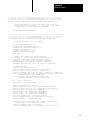
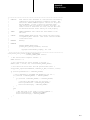
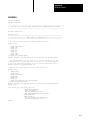
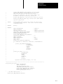
Table of Contents
Summary of Changes . . . . . . . . . . . . . . . . . . . . . . . . . . . .
i
Using this Manual . . . . . . . . . . . . . . . . . . . . . . . . . . . . . . .
iii
Manual Objectives . . . . . . . . . . . . . . . . . . . . . . . . . . . . . . . . . . .
What this Manual Contains . . . . . . . . . . . . . . . . . . . . . . . . . . . . .
Audience . . . . . . . . . . . . . . . . . . . . . . . . . . . . . . . . . . . . . . . . .
Terms and Conventions . . . . . . . . . . . . . . . . . . . . . . . . . . . . . . .
Related Publications . . . . . . . . . . . . . . . . . . . . . . . . . . . . . . . . .
iii
iii
iii
iv
v
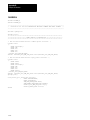
Overview . . . . . . . . . . . . . . . . . . . . . . . . . . . . . . . . . . . . . .
1-1
Chapter Objectives . . . . . . . . . . . . . . . . . . . . . . . . . . . . . . . . . .
Features . . . . . . . . . . . . . . . . . . . . . . . . . . . . . . . . . . . . . . . . . .
System Description . . . . . . . . . . . . . . . . . . . . . . . . . . . . . . . . . .
VMEbus Interface . . . . . . . . . . . . . . . . . . . . . . . . . . . . . . . . . . .
Compatibility with the Standard PLC-5 Processor . . . . . . . . . . . . .
Compatibility with the 6008-LTV Processor . . . . . . . . . . . . . . . . .
1-1
1-1
1-4
1-6
1-9
1-9
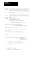
Installation . . . . . . . . . . . . . . . . . . . . . . . . . . . . . . . . . . . . .
2-1
Chapter Objectives . . . . . . . . . . . . . . . . . . . . . . . . . . . . . . . . . .
Handling the Processor . . . . . . . . . . . . . . . . . . . . . . . . . . . . . . .
Setting the Switches . . . . . . . . . . . . . . . . . . . . . . . . . . . . . . . . .
Configuring the VME Backplane Jumpers . . . . . . . . . . . . . . . . . .
Inserting the Processor into a Chassis . . . . . . . . . . . . . . . . . . . . .
Grounding . . . . . . . . . . . . . . . . . . . . . . . . . . . . . . . . . . . . . . . . .
Determining Power-Supply Requirements . . . . . . . . . . . . . . . . . .
Connecting to Remote I/O . . . . . . . . . . . . . . . . . . . . . . . . . . . . .
Connecting an Extended-Local I/O Link . . . . . . . . . . . . . . . . . . . .
Connecting a DH+ Link . . . . . . . . . . . . . . . . . . . . . . . . . . . . . . .
Connecting a Programming Terminal to Channel 0 . . . . . . . . . . . .
Installing, Removing, and Disposing of the Battery . . . . . . . . . . . .
2-1
2-2
2-2
2-4
2-5
2-5
2-6
2-6
2-10
2-12
2-14
2-15
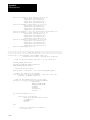
VMEbus Interface . . . . . . . . . . . . . . . . . . . . . . . . . . . . . . .
3-1
Chapter Objectives . . . . . . . . . . . . . . . . . . . . . . . . . . . . . . . . . .
System Controller . . . . . . . . . . . . . . . . . . . . . . . . . . . . . . . . . . .
Bus-Release Modes . . . . . . . . . . . . . . . . . . . . . . . . . . . . . . . . .
VME LEDs . . . . . . . . . . . . . . . . . . . . . . . . . . . . . . . . . . . . . . . .
VME Signal Usage . . . . . . . . . . . . . . . . . . . . . . . . . . . . . . . . . . .
Configuration Registers . . . . . . . . . . . . . . . . . . . . . . . . . . . . . . .
Commands . . . . . . . . . . . . . . . . . . . . . . . . . . . . . . . . . . . . . . . .
3-1
3-1
3-2
3-2
3-3
3-4
3-7
ii
Table of Contents
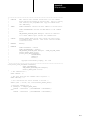
Ladder-Program Interfaces . . . . . . . . . . . . . . . . . . . . . . . .
4-1
Chapter Objectives . . . . . . . . . . . . . . . . . . . . . . . . . . . . . . . . . .
Ladder Messages . . . . . . . . . . . . . . . . . . . . . . . . . . . . . . . . . . .
Message Completion and Status Bits . . . . . . . . . . . . . . . . . . . . .
VME Status File . . . . . . . . . . . . . . . . . . . . . . . . . . . . . . . . . . . . .
Continuous Copy to/from VME . . . . . . . . . . . . . . . . . . . . . . . . . .
VMEbus Interrupts . . . . . . . . . . . . . . . . . . . . . . . . . . . . . . . . . . .
4-1
4-1
4-6
4-7
4-10
4-11
Commands . . . . . . . . . . . . . . . . . . . . . . . . . . . . . . . . . . . .
5-1
Chapter Objectives . . . . . . . . . . . . . . . . . . . . . . . . . . . . . . . . . .
Command Types . . . . . . . . . . . . . . . . . . . . . . . . . . . . . . . . . . . .
Continuous-Copy Commands . . . . . . . . . . . . . . . . . . . . . . . . . . .
Handle-Interrupts Command . . . . . . . . . . . . . . . . . . . . . . . . . . . .
Send-PCCC Command . . . . . . . . . . . . . . . . . . . . . . . . . . . . . . .
Command-Protocol Error Codes . . . . . . . . . . . . . . . . . . . . . . . . .
Response-Word Error Codes . . . . . . . . . . . . . . . . . . . . . . . . . . .
5-1
5-1
5-2
5-5
5-7
5-8
5-8
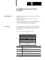
PLC-5/VME Processor Communications Commands . . . . .
6-1
Chapter Objectives . . . . . . . . . . . . . . . . . . . . . . . . . . . . . . . . . .
PCCC Structure . . . . . . . . . . . . . . . . . . . . . . . . . . . . . . . . . . . . .
Supported PCCCs . . . . . . . . . . . . . . . . . . . . . . . . . . . . . . . . . . .
Header Bit/Byte Descriptions . . . . . . . . . . . . . . . . . . . . . . . . . . .
Echo . . . . . . . . . . . . . . . . . . . . . . . . . . . . . . . . . . . . . . . . . . . . .
Identify Host and Status . . . . . . . . . . . . . . . . . . . . . . . . . . . . . . .
Read-Modify-Write . . . . . . . . . . . . . . . . . . . . . . . . . . . . . . . . . . .
Typed Read . . . . . . . . . . . . . . . . . . . . . . . . . . . . . . . . . . . . . . .
Data Types . . . . . . . . . . . . . . . . . . . . . . . . . . . . . . . . . . . . . . . .
Typed Write . . . . . . . . . . . . . . . . . . . . . . . . . . . . . . . . . . . . . . . .
Set CPU Mode . . . . . . . . . . . . . . . . . . . . . . . . . . . . . . . . . . . . .
Upload All Request . . . . . . . . . . . . . . . . . . . . . . . . . . . . . . . . . .
Download All Request . . . . . . . . . . . . . . . . . . . . . . . . . . . . . . . .
Upload Complete . . . . . . . . . . . . . . . . . . . . . . . . . . . . . . . . . . . .
Download Complete . . . . . . . . . . . . . . . . . . . . . . . . . . . . . . . . . .
Read Bytes Physical . . . . . . . . . . . . . . . . . . . . . . . . . . . . . . . . .
Write Bytes Physical . . . . . . . . . . . . . . . . . . . . . . . . . . . . . . . . .
Get Edit Resource . . . . . . . . . . . . . . . . . . . . . . . . . . . . . . . . . . .
Return Edit Resource . . . . . . . . . . . . . . . . . . . . . . . . . . . . . . . . .
Apply Port Configuration . . . . . . . . . . . . . . . . . . . . . . . . . . . . . . .
Restore Port Configuration . . . . . . . . . . . . . . . . . . . . . . . . . . . . .
Upload and Download Procedure . . . . . . . . . . . . . . . . . . . . . . . .
6-1
6-1
6-3
6-4
6-5
6-6
6-8
6-10
6-12
6-18
6-20
6-21
6-23
6-24
6-25
6-26
6-27
6-29
6-30
6-31
6-32
6-34
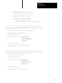
Table of Contents
iii
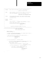
Performance and Operation . . . . . . . . . . . . . . . . . . . . . . . .
7-1
Chapter Objectives . . . . . . . . . . . . . . . . . . . . . . . . . . . . . . . . . .
VME Throughput Time . . . . . . . . . . . . . . . . . . . . . . . . . . . . . . . .
Communication Methods . . . . . . . . . . . . . . . . . . . . . . . . . . . . . .
Benchmark Tests . . . . . . . . . . . . . . . . . . . . . . . . . . . . . . . . . . . .
Introduction to PLC-5/VME Processor Scanning . . . . . . . . . . . . . .
Discrete and Block Transfer I/O Scanning . . . . . . . . . . . . . . . . . .
7-1
7-1
7-2
7-4
7-7
7-12
Sample Applications . . . . . . . . . . . . . . . . . . . . . . . . . . . . .
A-1
Appendix Objectives . . . . . . . . . . . . . . . . . . . . . . . . . . . . . . . . .
VMEDEMO.CPP . . . . . . . . . . . . . . . . . . . . . . . . . . . . . . . . . . . .
VMEDEMO.MAK . . . . . . . . . . . . . . . . . . . . . . . . . . . . . . . . . . . .
UPLOAD.CPP . . . . . . . . . . . . . . . . . . . . . . . . . . . . . . . . . . . . . .
UPLOAD.MAK . . . . . . . . . . . . . . . . . . . . . . . . . . . . . . . . . . . . .
DOWNLOAD.CPP . . . . . . . . . . . . . . . . . . . . . . . . . . . . . . . . . . .
DOWNLOAD.MAK . . . . . . . . . . . . . . . . . . . . . . . . . . . . . . . . . . .
A-1
A-2
A-13
A-15
A-26
A-27
A-34
Sample Application Programming Interface Modules . . . . .
B-1
Appendix Objectives . . . . . . . . . . . . . . . . . . . . . . . . . . . . . . . . .
COMMON.H . . . . . . . . . . . . . . . . . . . . . . . . . . . . . . . . . . . . . . .
COMMON.C . . . . . . . . . . . . . . . . . . . . . . . . . . . . . . . . . . . . . . .
P40VCC0.H . . . . . . . . . . . . . . . . . . . . . . . . . . . . . . . . . . . . . . .
P40VCC0.C . . . . . . . . . . . . . . . . . . . . . . . . . . . . . . . . . . . . . . .
PCCC.H . . . . . . . . . . . . . . . . . . . . . . . . . . . . . . . . . . . . . . . . . .
P40VHINT.H . . . . . . . . . . . . . . . . . . . . . . . . . . . . . . . . . . . . . . .
P40VHINT.C . . . . . . . . . . . . . . . . . . . . . . . . . . . . . . . . . . . . . . .
P40VSPCC.H . . . . . . . . . . . . . . . . . . . . . . . . . . . . . . . . . . . . . .
P40VSPCC.C . . . . . . . . . . . . . . . . . . . . . . . . . . . . . . . . . . . . . .
P40VWBP.H . . . . . . . . . . . . . . . . . . . . . . . . . . . . . . . . . . . . . . .
P40VWBP.C . . . . . . . . . . . . . . . . . . . . . . . . . . . . . . . . . . . . . . .
P40VAPC.H . . . . . . . . . . . . . . . . . . . . . . . . . . . . . . . . . . . . . . .
P40VAPC.C . . . . . . . . . . . . . . . . . . . . . . . . . . . . . . . . . . . . . . .
P40VULC.H . . . . . . . . . . . . . . . . . . . . . . . . . . . . . . . . . . . . . . .
P40VULC.C . . . . . . . . . . . . . . . . . . . . . . . . . . . . . . . . . . . . . . .
P40VDLA.H . . . . . . . . . . . . . . . . . . . . . . . . . . . . . . . . . . . . . . .
P40VDLA.C . . . . . . . . . . . . . . . . . . . . . . . . . . . . . . . . . . . . . . .
P40VDLC.H . . . . . . . . . . . . . . . . . . . . . . . . . . . . . . . . . . . . . . .
P40VDLC.C . . . . . . . . . . . . . . . . . . . . . . . . . . . . . . . . . . . . . . .
P40VECHO.H . . . . . . . . . . . . . . . . . . . . . . . . . . . . . . . . . . . . . .
P40VECHO.C . . . . . . . . . . . . . . . . . . . . . . . . . . . . . . . . . . . . . .
P40VGER.H . . . . . . . . . . . . . . . . . . . . . . . . . . . . . . . . . . . . . . .
P40VGER.C . . . . . . . . . . . . . . . . . . . . . . . . . . . . . . . . . . . . . . .
P40VIHAS.H . . . . . . . . . . . . . . . . . . . . . . . . . . . . . . . . . . . . . . .
P40VIHAS.C . . . . . . . . . . . . . . . . . . . . . . . . . . . . . . . . . . . . . . .
B-1
B-3
B-5
B-17
B-18
B-30
B-32
B-33
B-39
B-40
B-43
B-44
B-46
B-47
B-49
B-50
B-52
B-53
B-55
B-56
B-58
B-59
B-61
B-62
B-64
B-67
iv
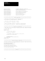
Table of Contents
P40VRBP.H . . . . . . . . . . . . . . . . . . . . . . . . . . . . . . . . . . . . . . .
P40VRBP.C . . . . . . . . . . . . . . . . . . . . . . . . . . . . . . . . . . . . . . .
P40VRER.H . . . . . . . . . . . . . . . . . . . . . . . . . . . . . . . . . . . . . . .
P40VRER.C . . . . . . . . . . . . . . . . . . . . . . . . . . . . . . . . . . . . . . .
P40VRMW.H . . . . . . . . . . . . . . . . . . . . . . . . . . . . . . . . . . . . . . .
P40VRMW.C . . . . . . . . . . . . . . . . . . . . . . . . . . . . . . . . . . . . . . .
P40VRPC.H . . . . . . . . . . . . . . . . . . . . . . . . . . . . . . . . . . . . . . .
P40VRPC.C . . . . . . . . . . . . . . . . . . . . . . . . . . . . . . . . . . . . . . .
P40VSCM.H . . . . . . . . . . . . . . . . . . . . . . . . . . . . . . . . . . . . . . .
P40VSCM.C . . . . . . . . . . . . . . . . . . . . . . . . . . . . . . . . . . . . . . .
P40VULA.H . . . . . . . . . . . . . . . . . . . . . . . . . . . . . . . . . . . . . . .
P40VULA.C . . . . . . . . . . . . . . . . . . . . . . . . . . . . . . . . . . . . . . .
B-69
B-70
B-72
B-73
B-75
B-76
B-80
B-81
B-83
B-84
B-86
B-87
Specifications . . . . . . . . . . . . . . . . . . . . . . . . . . . . . . . . . .
C-1
Environmental Specifications . . . . . . . . . . . . . . . . . . . . . . . . . . .
VMEbus Specifications . . . . . . . . . . . . . . . . . . . . . . . . . . . . . . .
C-1
C-2
Troubleshooting . . . . . . . . . . . . . . . . . . . . . . . . . . . . . . . .
D-1
Appendix Objectives . . . . . . . . . . . . . . . . . . . . . . . . . . . . . . . . .
VME Backplane Jumpers . . . . . . . . . . . . . . . . . . . . . . . . . . . . . .
VME LEDs . . . . . . . . . . . . . . . . . . . . . . . . . . . . . . . . . . . . . . . .
Message Completion and Status Bits Error Codes . . . . . . . . . . . .
Continuous-Copy Error Codes . . . . . . . . . . . . . . . . . . . . . . . . . .
Command-Protocol Error Codes . . . . . . . . . . . . . . . . . . . . . . . . .
Response-Word Error Codes . . . . . . . . . . . . . . . . . . . . . . . . . . .
PCCC Command Status Codes . . . . . . . . . . . . . . . . . . . . . . . . .
Avoiding Multiple Watchdog Faults1. . . . . . . . . . . . . . . . . . . . . . .
Inserting Ladder Rungs at the 56K-Word Limit . . . . . . . . . . . . . . .
Recovering from Possible Memory Corruption . . . . . . . . . . . . . . .
Examining Fault Codes . . . . . . . . . . . . . . . . . . . . . . . . . . . . . . .
Avoiding Run-time Errors when Executing FBC and
DDT Instructions . . . . . . . . . . . . . . . . . . . . . . . . . . . . . . . . .
D-1
D-1
D-1
D-2
D-2
D-2
D-3
D-3
D-5
D-5
D-6
D-6
Cable Connections . . . . . . . . . . . . . . . . . . . . . . . . . . . . . .
E-1
Cable Connections for Communication Boards . . . . . . . . . . . . . . .
Cable Connections for Serial-Port Communications . . . . . . . . . . .
Front Panel . . . . . . . . . . . . . . . . . . . . . . . . . . . . . . . . . . . . . . . .
Cable Pin Assignments . . . . . . . . . . . . . . . . . . . . . . . . . . . . . . .
Cable Specifications . . . . . . . . . . . . . . . . . . . . . . . . . . . . . . . . .
E-1
E-1
E-2
E-6
E-7
D-6
Table of Contents
v
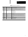
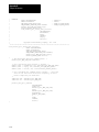
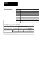
Figures/Tables
Compliance to European Union Directives . . . . . . . . . . . . . . . . . .
Figure 2.3
Terminating a Remote I/O Link Using a Resistor . . . . . . . . . . .
Figure 2.4
Programming Terminal to Channel 0 of a PLC-5/VME Processor
Figure 2.5
Installing a Processor Battery (cat. no. 1770-XYV) . . . . . . . . . .
Table 2.C
Programming Terminal to Channel 0 Interconnect Cables . . . .
2-1
2-9
2-14
2-15
2-14
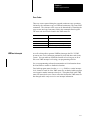
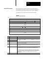
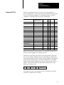
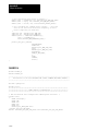
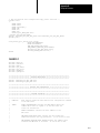
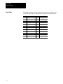
Summary of Changes
Summary of Changes
This release of the PLC-5/VME VMEbus Programmable Controllers User
Manual contains new and updated information on PLC-5/VMEt systems.
For infornmation about:
See chapter/appendix:
CE compliance
2
making VME self-references in POST tests
2
improved .WRDY and .LOCK bit description
3
changes to the status file
4
setting the NOCV bit to 0
7
revised specifications
C
additional troubleshooting tips
D
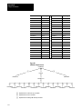
To help you find new and updated information in this release of the
manual, we have included change bars as shown to the left of
this paragraph.
In addition to the new and updated information discussed above, we have
altered the way we reference software documentation in this manual.
Rather than show specific screens and key sequences which may vary
according to the software package you are using, we refer you instead to
the programming software documentation that accompanies your particular
software package. Of course, we still provide the basic background
information you need to accomplish your programming tasks, but if you
have specific questions, you should refer to your programming software
documentation set.
vii
Preface
Using this Manual
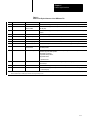
Manual Objectives
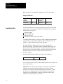
What this Manual Contains
Audience
The purpose of this manual is to familiarize you with the installation and
use of the PLC-5/VME programmable controllers. This manual focuses on
the specific VMEbus aspects of this processor. Typically, you use this
processor in a VMEbus system with one or more host CPU modules that
control(s) and communicate(s) with the processor. You need to develop
software driver programs to execute on the host CPU module(s) to
accomplish this. You must also write ladder programs for your processor
to monitor and control the I/O of your control system. This manual helps
you write the VMEbus-specific aspects of these programs.
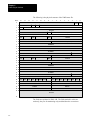
Chapter/
Appendix
Title
Contents
1
Overview
Overview of the PLC-5/VME processors
2
Installation
Configuration and installation procedures
3
VMEbus Interface
Configuration registers and commands
4
Ladder-Program Interfaces
How to interact with your VMEbus environment from
your ladder program
5
Commands
Commands used to interface to the processor
6
PLC-5/VME Processor
Communications Commands
The function of the extended PCCCs in the
PLC-5/VME processor
7
Performance and Operation
Overview of the performance and operation of the
PLC-5/VME processor
A
Sample Applications
How to write applications to interact with your
PLC-5/VME processor
B
Sample API Modules
How to write API modules to interact with your
PLC-5/VME processor
C
Specifications
PLC-5/VME processor specifications
D
Troubleshooting
Troubleshooting and error-code information
E
Cable Connections
Communication boards and cable connections for
PLC-5 family processors
This manual assumes that you have background in:
VMEbus concepts and basics
PLC-5 ladder logic
PLC-5/VME operation
C-language programming
iii
Preface
Using this Manual
Terms and Conventions
We refer to the:
As the:
Data Highway
DH link
Data Highway Plus
DH+ link
Programmable Logic Controller
processor
PLC-5 Processor
PLC-5/VME processor. Unless noted otherwise,
we use PLC-5/VME processor to denote all processors.
Programmable Controller
Communications Commands
PCCC
Release on request
ROR
Release when done
RWD
Term
Definition
Extended-local I/O
I/O connected to a processor across a parallel link, thus limiting its
distance from the processor
Extended-local I/O link
a parallel link for carrying I/O data between a PLC-5/V40L
processor and extended-local I/O adapters
Remote I/O link
a serial communication link between a PLC-5 processor port in
scanner mode and an adapter as well as I/O modules that are
located remotely from the PLC-5 processor
Remote I/O chassis
the hardware enclosure that contains an adapter and I/O modules
that are located remotely on a serial communication link to a
PLC-5 processor in scanner mode
Discrete-transfer data
data (words) transferred to/from a discrete I/O module
Block-transfer data
data transferred, in blocks of data up to 64 words, to/from a blocktransfer I/O module (for example, an analog module)
In addition, you may encounter words in different typefaces. We use these
conventions to help differentiate descriptive information from information
that you enter while programming your processor.
The Enter key looks like this (boldface and in brackets):
[Enter]
Words or commands that you enter appear in boldface. For example:
CTV #
SVI
Variables that you enter appear in italics. For example:
vmeaddr width
“Type” means type in the information.
“Enter” means type in the information and then press the [Enter] key.
iv
Preface
Using this Manual
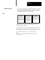
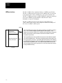
Related Publications
The 1785 PLC-5 programmable controller documentation is organized
into manuals according to the tasks that you perform. This organization
lets you find the information that you want without reading through
information that is not related to your current task.
Enhanced PLC-5
Processors System
System Overview
Enhanced and Ethernet
PLC-5 Programmable
Controller User Manual
Overview of processor
specifications. selection,
and justification information
Explanation of processor
functionality, system
design, and programming
considerations
1785-2.36
1785-6.5.12
1785 PLC-5
Programmable Controllers
Quick Reference
Quick access to switches,
status bits, indicators,
instructions, SW screens
1785-7.1
For more information on 1785 PLC-5 programmable controllers or the
above publications, contact your local Allen-Bradley sales office,
distributor, or system integrator.
We also suggest that you acquire the following publications for reference:
Data Highway / Data Highway Plus DH-485 Communication Protocol
and Command Set Reference, Allen-Bradley, publication 1770-6.5.16
The VMEbus Specification—Rev: C.1, Motorola, HB212
VMEbus User’s Handbook, Steve Heath, CRC Press, ISBN
0-8493-7130-9
v
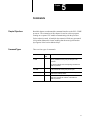
Chapter
1
Overview
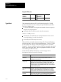
Chapter Objectives
Read this chapter to understand the overall operation of the PLC-5/VME
processor, how you can use it in VME systems, and how its features and
functions relate to those of other Allen-Bradley processors.
Features
PLC-5/VME processors are programmable controllers that bring the
technology of the 1785 PLC-5 processor to the VMEbus environment.
The PLC-5/VME processor is equivalent (in terms of I/O, ladder
programming, and instruction timing) to the standard PLC-5 processor,
except that the PLC-5/VME processor:
plugs into a VMEbus system
has a VMEbus communication interface designed for use with other
VMEbus CPU modules
can access VMEbus I/O modules
has no EEPROM memory module
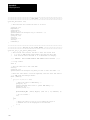
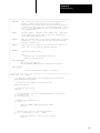
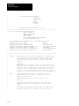
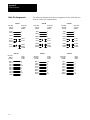
Figure 1.1 shows examples of the PLC-5/VME processors.
1-1
Chapter 1
Overview
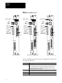
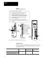
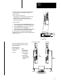
Figure 1.1
Examples of PLC-5/VME Processors
Battery installed
Battery installed
Program
Remote
Run
Battery installed
Program
Remote
Run
Chan 1
Battery low
Proc run/Fault
Force
Ch 0 Status
SYSFAIL
Master Access
Slave Access
Program
Remote
Run
Chan 1
Battery low
Proc run/Fault
Force
Ch 0 Status
SYSFAIL
Master Access
Slave Access
1A
1A
1B
Chan 1
Battery low
Proc run/Fault
Force
Ch 0 Status
SYSFAIL
Master Access
Slave Access
1A
1B
Chan 0
Chan 0
1B
Chan 0
Chan 2
PLC-5/V30B processor
PLC-5/V40B or -5/V80B processor
Chan 2
PLC-5/V40L processor
19499
All PLC-5/VME processors have at least one configurable I/O channel and
one serial port (channel 0).
Channel:
Is configured for:
0
supporting RS-232C
The PLC-5/VME processor channel 0 protocol defaults to the system mode of
operation (DF1 point-to-point), which allows programming from a PC terminal.
The default communication rate is 2400.
1-2
1A
DH+ mode (by default)
1B
scanner mode (by default)
2 (if applicable)
DH+ and remote I/O (RIO) communication or extended-local I/O
Chapter 1
Overview
In the PLC-5/V40B, both channels (1 and 2) are identical although they are
independently configurable. In the PLC-5/V40L, channel 2 is a local I/O
(LIO) interface.
The PLC-5/VME processor has the same instruction set as the standard
PLC-5 processor. It supports:
complex expressions in compare and compute instructions
statistical instructions
floating-point calculations in PID instructions
ASCII string-handling instructions
main control programs (MCPs)
Use the keyswitch to change the mode in which a processor is operating.
If you want to:
Turn the keyswitch to:
RUN
• Run your program, force I/O, and save your programs to a
disk drive. Outputs are enabled. (Equipment being
controlled by the I/O addressed in the ladder program begins
operation.)
• Enable outputs.
Note: You cannot create or delete a program file, create or
delete data files, or change the modes of operation
through the programming software while in
run mode.
• Disable outputs
• Create, modify, and delete ladder files or data files;
download to an EEPROM module; and save/restore
programs.
Notes:
• The processor does not scan the program.
• You cannot change the mode of operation through
the programming software while in program mode.
PROG
R
E
M
RUN
PROG (program)
PROG
R
E
M
RUN
Change between remote program, remote test, and remote run REM (remote)
modes through the programming software.
Remote run
• Enable outputs.
• You can save/restore files and edit online.
Remote program
PROG
R
E
M
RUN
See the program-mode description above.
Remote test
• Execute ladder programs with outputs disabled.
• You cannot create or delete ladder programs or data files.
1-3
Chapter 1
Overview
System Description
CPU
PLC-5/VME
processor
Use the PLC-5/VME processor in a 6U (full-height) VMEbus chassis. You
can use the PLC-5/VME processor by itself (i.e., with no other VME
modules), but typically the PLC-5/VME processor is used in conjunction
with other VMEbus computers (CPUs) and I/O modules. The examples
below illustrate possible configurations.
DH+ link
The PLC-5/VME processor is used in conjunction with a VMEbus CPU module. The
processor serves as a real-time I/O processor under the direction of the CPU. The
processor is a slave of the CPU, where, in addition to its normal ladder logic and I/O
processing in each scan loop, the processor responds to directions from the CPU and
passes data back to the CPU.
Remote I/O
or ExtendedLocal I/O
CPUs
PLC-5/VME processor
There is no fixed relationship between processor and CPU, so multiple CPUs can
communicate with one processor. Multiple CPUs run multiple tasks, all sending and
receiving data from the processor at the same time.
19500
CPU
One CPU can control multiple PLC-5/VME processors. Each processor maps into the
VMEbus address space; so you map each processor to a different address space.
PLC-5/VME processors
PLC-5/VME processor
No CPU interacts with the processor. The processor interacts with I/O modules in one
or more remote I/O racks and has the capability, from its ladder program, of generating
VMEbus accesses. This means that the processor can access VMEbus I/O modules
as well.
19500
1-4
Chapter 1
Overview
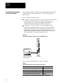
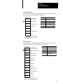
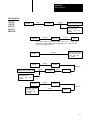
The following diagrams show three basic configurations for programming
and debugging your ladder-logic programs.
PLC-5/VME
processor
DH+ link
PLC-5/VME processor
Connect a computer via the DH+ link, typically using a
1784-KT communication device in your IBM AT computer
and a 1784-CP6 cable.
Connect a computer using the RS-232C on-board serial
port of the PLC-5/VME processor. In this configuration, the
RS-232C cable connects one of the computer’s COM ports
to the channel 0 (serial) port of the processor.
RS-232
PC/CPU PLC-5/VME processor
You can program as well as download files directly over the
VMEbus backplane to your PLC-5/VME processor if you:
run 6200 Series PLC-5 Programming Software release
4.4 or later
use an 8086-based CPU from RadiSys—i.e., a EPC-1,
EPC-4, or EPC-5 VME PC-compatible computer.
19501
Important: In order to use the save feature of the 6200
Series PLC-5 Programming Software when you
communicate with the processor in this way, you must run
release 4.5 or later.
1-5
Chapter 1
Overview
VMEbus Interface
The PLC-5/VME is fully compliant with the C.1 VMEbus specification.
The PLC-5/VME processor occupies two 6U VMEbus slots. It can reside
in any adjacent pair of slots, including slot 1, the system-controller slot.
The PLC-5/VME processor has a single VMEbus P1 connector, allowing it
to be used in VMEbus systems that have either the full J1 and J2
backplanes or only the J1 backplane.
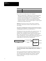
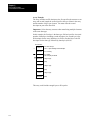
The PLC-5/VME processor occupies 64 bytes in the VME A16 (or
“short”) address space, and you can configure an additional 64 Kbytes of
the A24 (or “standard”) address space.
VMEbus
Configuration/control/
status/message
registers in A16 space
Optional general-purpose
memory in A24 space
Processor
1-6
The PLC-5/VME processor has 8 16-bit registers accessible in the VMEbus A16 address
space. A set of switches establishes the base address of these registers. These
registers can be used by a VMEbus CPU to establish certain programmable configuration
options of the processor, control and monitor certain low-level conditions, and send
commands to the processor.
The PLC-5/VME processor also has 64 KB of memory that can be enabled and mapped
in the VME A24 address space. This memory is a general-purpose memory that you can
use for any purpose (or not at all). If you enable it and tell the processor to do something
to a VME address that happens to fall into this 64KB memory, the processor can access it
without actually using VMEbus cycles. If you need some global VMEbus memory that
can be accessed by the processor and another CPU, there may be performance benefits
to using this 64KB of memory.
Chapter 1
Overview
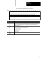
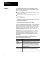
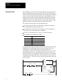
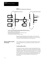
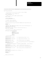
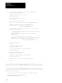
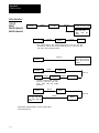
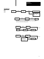
Figure 1.2 illustrates the basic forms of communications. Table 1.A
summarizes these communication forms.
Figure 1.2
Basic Forms of Communications
1
Commands sent to the processor
Ladder
programs
2
Read/write accesses to the processor’s A16 registers and/or
the A24 memory block
3
Interrupt to a ladder program
4
Interrupt signalled by a ladder program
5
One-shot block copy into or out of processor data files
6
Continuous block copies into or out of processor data files
7
Interrupt signalling command completion
8
Interrupt signalling completion of one block copy
9
Processor
data
Files
One-shot block copy into or out of processor data files as a
result of some commands sent to the processor
10
VMEbus SYSRESET
11
VMEbus SYSFAIL
12
VMEbus ACFAIL 1
VME status file
13
1
Optional VMEbus system controller functions
Required by the PLC-5/VME processor. Asserted by VME power supply.
1-7
Chapter 1
Overview
Table 1.A
Summary of Figure 1.2
In Figure 1.2,
when you see :
It means that:
1
Commands are high-level directives sent to the processor from another VMEbus master, typically a
controlling CPU. Commands specific to the VME processor can establish a continuous block copy to/from
the processor and tell the processor to which VMEbus interrupts it should respond. You can also send any
PCCC via this mechanism. PCCCs are commands supported in all 1785 PLC-5 processors. You can use
them to change and modify processor state, for example, or to upload and download memory files.
2
The PLC-5/VME processor responds as a VMEbus slave to certain A16 accesses (to its configuration
registers) and to certain A24 accesses (to its general-purpose memory, if enabled).
3
You can configure the PLC-5/VME processor to respond as an interrupt handler to specified VMEbus
interrupt lines. When one of these interrupts occurs, the processor performs an 8-bit interrupt acknowledge
cycle on the VMEbus to read an 8-bit status/ID from the interrupter. The interrupt and the status/ID value
are then posted for accessibility by the ladder program.
4
The PLC-5/VME processor can perform as a VMEbus interrupter (sender of interrupts) in three
different ways:
• from a ladder program; the ladder MSG instruction has been extended in the PLC-5/VME processor to
allow a ladder program to generate a VMEbus interrupt.
• signalling completion of a command (see 7).
• signalling a completion of each block copy operation for the continuous copy operations (see 8).
5
Another function available via the MSG instruction is VMEbus reads and writes. Rather than just individual
8- or 16-bit accesses, the function allows a block read or write to be done (i.e., of an arbitrary number of
bytes). This is done between a data file in the processor and an arbitrary address range on the VMEbus.
The ladder program can specify the VMEbus address space and data widths to be used.
6
One of the main interfaces of the 6008-LTV processor, and one preserved in the PLC-5/VME processor, is
the ability to predefine two block-copy operations, one into the processor data files and one out of the
processor data files, to be executed automatically every scan loop. These operations are predefined to the
processor via initialization commands from the CPU or from your programming software.
7
The processor can be a VMEbus interrupter signalling completion of a command. This is an option on all
commands and can serve as a way to synchronize the CPU and the processor.
8
The processor can be a VMEbus interrupter signalling completion of each block copy operation for the
continuous copy operations. This is another option that allows the CPU to synchronize with the scan loop
of the processor.
9
Certain standard PCCC commands cause data to be moved into and out of the processor; thus these
commands represent another type of VMEbus interface between the processor and a controlling CPU.
10
The PLC-5/VME processor can be reset with the VME SYSRESET1 signal. The PLC-5/VME processor
also asserts SYSRESET1 during power-up initialization until its VMEbus interface hardware is capable of
responding to VMEbus accesses.
11
The PLC-5/VME processor asserts the VME SYSFAIL1 signal after a reset until the firmware’s self-test
completes successfully. The PLC-5/VME processor makes the state of the VME SYSFAIL1 signal
available to the ladder program.
12
Assertion of VME ACFAIL1 causes the processor to halt, with integrity of the ladder program and data files
maintained in the battery-backed memory such that the processor can be restarted upon power up. Your
power supply must assert ACFAIL1 at least 9ms in advance of the +5VDC supply dropping beneath 4.75V.
13
The PLC-5/VME processor can serve as a VMEbus slot-1 system controller. This enables the PLC-5/VME
processor as a single-level arbiter, a bus timeout timer, and the driver of the VMEbus 16 MHz
SYSCLK signal.
1 indicates a low true signal.
1-8
Chapter 1
Overview
Compatibility with the
Standard PLC-5 Processor
Ladder programs from a standard PLC-5 processor run in the PLC-5/VME
processor. The PLC-5/VME processor has the same program scan time as
the PLC-5 processor. The PLC-5/VME processor has the same extended
instruction set as the PLC-5 processor.
Features of the PLC-5 processor not present in the PLC-5/VME
processor are:
PIIs
EEPROM memory module
logical rack 0 (128 less I/O points)
Features of the PLC-5/VME processor not present in the PLC-5
processor are:
The PLC-5/VME processor defines a special data file called the “VME
status file.” This file gives ladder programs the ability to control and
monitor certain VMEbus state information.
The ladder MSG instruction is extended to allow ladder programs to
perform VMEbus data transfers and generate VMEbus interrupts.
Finally, features present in both but implemented or represented
differently are:
The serial port (channel 0) on the PLC-5/VME processor is RS-232C
only (not configurable for RS-422 and RS-423).
Different batteries are used (cat. no. 1770-XYV).
The PLC-5/VME processor has a memory-protect switch. In the PLC-5
processor, the equivalent switch is on the 1771 I/O rack.
Compatibility with the
6008-LTV Processor
The PLC-5/VME processor retains a significant amount of compatibility
with the 6008-LTV processor. This eases the task of converting 6008-LTV
ladder programs and CPU driver programs to use with the PLC-5/VME
processor.
6008-LTV ladder programs may need editing because the VME status file
in the PLC-5/VME processor is different in several ways from 6008-LTV
status file. The 6008-LTV ladder programs that access the VME status file
will need to be changed.
1-9
Chapter 1
Overview
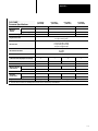
Table 1.B
Comparison of 6008-LTV and PLC-5/VME Processor Attributes
Attributes
6008-LTV
PLC-5/VME
Comments
VME slots
3
2
Bus arbitration
No
Yes or No (user configurable)
VME master
Yes
Yes
VME Slave
Yes
Yes
Global memory (bytes)1
1K short, 4K short or standard 64K standard
Global memory is selectable
Programming and downloading
over backplane
No
Yes
With 6200 series software
release 4.4 and later
Saving over backplane
No
Yes
With 6200 series software
release 4.5 and later
PLC data table to global memory trans- Continuous-copy command
fer method
Continuous-copy and/or ladder
MSG commands
Asserts VME SYSFAIL
Yes
Yes
PLC resets upon VME SYSRESET
Yes
Yes
Bus request line
0, 1, 2, 3
1, 3
Bus release
ROR, RWD, ROC
ROR, RWD, ROC
Continuous-copy command file size
500 words
1000 words
Ladder MSG file size
N/A
1000 words
RS-232 port
No
Yes
Remote I/O baud rate
57.6k baud fixed
57.6k, 115.2k, 230.4k baud configurable
Remote I/O fractional rack addressing
No
Yes
Single level arbiter
1
All of the 6008-LTV’s global memory could be configured to be totally within short memory. Because the PLC-5/VME processor’s global memory would totally fill all of
VME short memory, it can only be selected with a standard memory address. This may be a consideration when replacing a 6008-LTV with a PLC-5/VME processor.
There are some areas of potential incompatibility to consider:
The configuration/control/status/message registers are slightly different,
requiring changes to the host driver program.
The LTV VME global memory can be selected to be in short or standard
memory space. The PLC-5/VME processor’s global memory can only
be selected to be in standard memory. Because of this, the 6008-LTV
will accept address modifiers 2D, 3D 29 and 39. The PLC-5/VME
processor will only respond to address modifiers 3D.
The 6008-LTV supports logical rack address 0; the PLC-5/VME
processor does not.
The 6008-LTV has a status/configuration bit to enable or ignore ROC
(release on clear). The PLC-5/VME processor will always respond
to ROC.
1-10
Chapter 1
Overview
The PLV-5/VME processor status files in the processor status area are
different in several ways.
When floating point values are converted to integer, they are rounded
differently. 6008-LTV rounds 0.5 to the next highest integer, the
PLC-5/VME processor rounds to the nearest even integer.
CPU driver programs are affected in these ways:
The low-level protocol for how commands are given to the processor
and how command-sending errors are reported is significantly different.
However, the higher-level interfaces (e.g., the commands themselves)
are compatible.
The manner in which the VME setup interface parameters are
configured is significantly different:
In the:
The information is in the:
PLC-5/VME processor
configuration registers in the A16 space.
6008-LTV processor
“Slave 0” global memory in the A16 space.
See chapter 3 for more information.
1-11
Chapter
2
Installation
Chapter Objectives
Read this chapter to learn how to set the switches in your PLC-5/VME
processor and install it into a VMEbus chassis.
See the Classic 1785 PLC-5 Programmable Controller Hardware
Installation Manual, publication 1785-6.6.1 for more information about
installing PLC-5 family processors.
Compliance to
European Union Directives
If this product has the CE mark it is approved for installation within the
European Union and EEA regions. It has been designed and tested to meet
the following directives.
EMC Directive
This product is tested to meet Council Directive 89/336/EEC
Electromagnetic Compatibility (EMC) and the following standards, in
whole or in part, documented in a technical construction file:
• EN 50081-2EMC – Generic Emission Standard, Part 2 – Industrial
Environment
• EN 50082-2EMC – Generic Immunity Standard, Part 2 – Industrial
Environment
This product is intended for use in an industrial environment.
Low Voltage Directive
This product is tested to meet Council Directive 73/23/EEC Low Voltage,
by applying the safety requirements of EN 61131–2 Programmable
Controllers, Part 2 – Equipment Requirements and Tests.
For specific information required by EN 61131-2, see the appropriate
sections in this publication, as well as the following Allen-Bradley
publications:
• Industrial Automation Wiring and Grounding Guidelines For Noise
Immunity, publication 1770-4.1
• Enhanced and Ethernet PLC-5 Programmable Controller User
Manual, publication 1785-6.5.12
• Guidelines for Handling Lithium Batteries, publication AG-5.4
• Automation Systems Catalog, publication B111
2-1
Chapter 2
Installation
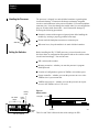
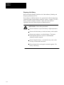
Handling the Processor
The processor is shipped in a static-shielded container to guard against
electrostatic damage. Electrostatic discharge can damage integrated
circuits or semiconductors in the processor module if you touch backplane
connector pins. It can also damage the module when you set configuration
plugs or switches inside the module. Avoid electrostatic damage by
observing the following precautions.
Remain in contact with an approved ground point while handling the
module (by wearing a properly grounded wrist strap).
Do not touch the backplane connector or connector pins.
Wrist strap
When not in use, keep the module in its static-shielded container.
19897
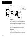
Setting the Switches
Before installing the PLC-5/VME processor, you need to make some
decisions about its configuration and operation and set the switches on the
circuit board accordingly. You need to know:
DH+ station (node) number
Memory protection—whether you want the processor’s program
RAM protected
Location of configuration registers in VMEbus A16 address space
System controller—whether you want the processor to serve as the
VMEbus slot-1 system controller
VMEbus request level—whether you want the processor to request
access to the VMEbus at level 3 or level 1
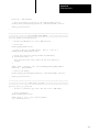
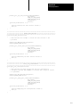
Figure 2.1
Switch Location
Memory
protect
Front plate
Powerup Test
DH+ station
number
Up
(off)
1
2
3
4
5
6
7
SW1 set of switches
2-2
8
Down
(on)
SW1
SW2
Bottom
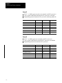
Table 2.A and Table 2.B describe the switch settings for SW1.
19502
Chapter 2
Installation
Table 2.A
SW1 Set of Switches
Switches 1-6
Switch 7
Switch 8
DH+ station number for channels
1A and 0 (see Table 2.B)
Unused (off)
Memory protect.
If on, RAM memory protect is enabled.
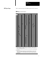
Table 2.B
Station Numbers SW1 (Switches 1-6)
LSD
MSD
Station
Number
N
mber
(Octal)
1
2
3
4
5
6
0
on
on
on
on
on
on
1
off
on
on
on
on
on
2
on
off
on
on
on
on
3
off
off
on
on
on
on
.
.
.
.
.
.
.
.
.
.
.
.
.
.
.
.
.
.
.
.
.
off
off
off
off
off
off
77
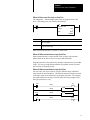
Table 2.C and Table 2.D describe the switch settings for SW2.
Table 2.C
SW2 Set of Switches
Switches 1-3
Switch 4
A16 address range of the If on, the processor functions as the VMEbus
configuration registers.
system controller, and no other VME cards
should attempt to be the system controller.
See Table 2.D.
Important: The PLC-5/VME processor must
be in the left-most slot of the VME chassis.
See page 3-1 for a description of the
system controller.
Switch 5
Switch 6
Unused
(off)
VMEbus request level.
Switch 7
Unused
1
If switch 4 is OFF, switch 6 on defines (off)
the bus request level as 3. If switch 6
is OFF, the bus request level is 1.
Switch 8
Unused
(off)
If switch 4 is ON, the bus request
level is 3 independent of the setting
of switch 6.
Important: Switch 6 is meaningful only if switch 4 is off.
1
SW2, position 7, now controls whether the PLC-5 processor makes a VME self-reference in its POST test. If you set SW2, position 7 to OFF (up position), then the VME will make
self-references as it did before series C, revision K. If you set SW2, position 7 to ON (down position), then the POST test will skip all VME self-references, causing the following effects:
– The PLC-5 processor cannot test its bus-master hardware.
– The PLC-5 processor cannot determine its own unique logical address and assumes its ULA is F0H regardless of how you set SW2, positions 1–3.
– The VME status file ULA field (word 1, bits 3-15) will always contain 000, regardless of how you set SW2, positions 1–3.
2-3
Chapter 2
Installation
Table 2.D
Address Range SW2 (Switches 1-3)
System
controller
ULA 1
Unused
(off)
Request
level
Unused
(off)
Unused
(off)
A16
address
range
Up
(off)
1
2
3
4
5
6
7
Down
(on)
8
SW2 set of switches
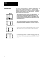
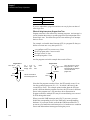
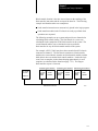
Configuring the VME
Backplane Jumpers
Five backplane jumpers
Left
connector
Right
connector
Backplane
2-4
PLC-5/VME processor
Empty
CPU
2
3
A16 Address Range
0
on
on
on
FC00-FC3F (hex)
1
off
on
on
FC40-FC7F
2
on
off
on
FC80-FCBF
3
off
off
on
FCC0-FCFF
4
on
on
off
FD00-FD3F
5
off
on
off
FD40-FD7F
6
on
off
off
FD80-FDBF
7
off
off
off
FDC0-FDFF
Unique Logical Address is used by the 6200 series
programming software to determine the A16 base address of
the PLC-5/VME processor’s registers..
The VMEbus contains several daisy-chained control signals. Almost all
VMEbus backplanes contain jumpers for these control signals to allow
systems to operate with empty slots. Failing to install these jumpers
properly is a common source of problems in configuring a new
VMEbus system.
There are five jumpers per VME slot, one for each of the four bus-grant
arbitration levels and one for the interrupt-acknowledge daisy chain.
Depending on the backplane manufacturer, the jumpers can be on the
rear pins of the J1 connector or alongside it on the front of the backplane.
The PLC-5/VME processor uses two slots. Based on what is in the VME
slot, install or remove the backplane jumpers as follows:
VME Slot Content
Five Backplane Jumpers
PLC-5/VME processor’s left slot
Remove
PLC-5/VME processor’s right slot
Install
Empty slot
Install
Other VME module
Consult manufacturer’s literature
Other VME module
Note: Consult
manufacturer’s
literature.
1
1
Chapter 2
Installation
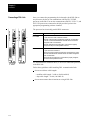
Inserting the Processor
into a Chassis
You insert the PLC-5/VME processor in two adjacent slots in a 6U
(full-height) VMEbus chassis.
ATTENTION: Make sure that your VME system is powered
off. The PLC-5/VME processor is not designed to be inserted
or removed from a live system.
ATTENTION: Avoid touching the circuit board
and connectors.
After sliding the processor into the VME chassis using its cardguides, use
firm pressure on the top and bottom handles of the processor to make its
P1 connector fit firmly into the connector on the backplane. Tighten the
screws in the top and bottom of the front panel to prevent your
PLC-5/VME processor from loosening.
19556
Grounding
Allen-Bradley makes specific recommendations for properly grounding its
racks so that their operation is as safe and error-free as possible. VME
systems, on the other hand, may have no formal specifications for
grounding the VME chassis frame. Allen-Bradley recommends that you
ground the VME chassis frame and that you connect the logic ground
(common) of the VME power supply to the chassis frame’s earth ground.
2-5
Chapter 2
Installation
The specific procedure for grounding a VME chassis varies depending on
the style of the chassis. Read the instructions found in the Classic PLC-5
Family Programmable Controllers Installation Manual, publication
1785-6.6.1 for information on how Allen-Bradley racks are grounded, and
try to ground your VME chassis frame in a similar way.
ATTENTION: If you are using a PLC-5/V40L processor,
your VME power supply should not float with respect to earth
ground. Connect the power supply’s logic ground (common)
for the 5V supply before connecting the PLC-5/40L processor
to a 1771-ALX adapter. Also, use a single point of ground
between the VME chassis and the extended-local I/O system to
ensure proper performance.
Determining Power-Supply
Requirements
The PLC-5/VME processor draws 4 A (maximum)—3.2 A (typical)—from
the VME power supply. The processor also monitors the ACFAIL signal
on the backplane to determine when the +5 VDC supply is within
tolerances. The VME power supply must assert ACFAIL at least 9 ms in
advance of the +5 VDC supply dropping beneath 4.75V or memory
corruption and processor fault occurs. Therefore, make sure that your
power supply has ACFAIL capability.
You must use a Safety Extra Low Voltage (SELV)- or Protected Extra Low
Voltage (PELV)-certified power supply with the VME processor to comply
with Low Voltage directive requirements.
Connecting to Remote I/O
Use Belden 9463 twin-axial cable (cat. no.1770-CD) to connect devices to
a remote I/O link. To connect a remote I/O link, do the following:
To connect a remote I/O link, you must:
See page:
Make sure the cables are the correct length
2-6
Prepare the cable
2-7
Make the remote I/O connections
2-7
Terminate the link
2-8
Make Sure that You Have Correct Cable Lengths
Verify that your system’s design plans specify remote I/O cable lengths
within allowable measurements.
2-6
Chapter 2
Installation
A remote I/O link using this communication rate:
Cannot exceed this cable length:
57.6 kbps
3,048 m (10,000 ft)
115.2 kbps
1,524 m (5,000 ft)
230.4 kbps
762 m (2,500 ft)
Prepare the Cable
Cut the cable according to the lengths you need. Route the cable to
the devices.
Make Remote I/O Connections
Use Figure 2.2 when connecting the remote I/O cable to PLC-5 processors
and remote I/O adapter modules.
2-7
Chapter 2
Installation
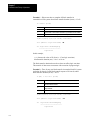
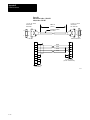
Figure 2.2
Remote I/O Terminal Connectors
To connect remote I/O cable, do the following:
1. Run the cable (1770-CD) from the processor to each remote I/O
adapter module or processor in the remote I/O system.
2. Connect the signal conductor with blue insulation to the 3-pin
connector terminal labeled 1 on the processor and to each remote
I/O adapter module (or PLC-5 adapter) in the remote I/O system.
3. Connect the signal conductor with clear insulation to the 3-pin
connector terminal labeled 2.
4. Connect the shield drain wire to the 3-pin terminal labeled SH.
5. Tie wrap the remote I/O network cable to the chassis to relieve strain
on the cable.
1 Line 1
2 Shield
Cable
3 Line 2
4 Line 1
Cable for
daisy-chain
5 Shield
configuration
6 Line 2
7 No Connection
8 No Connection
9 No Connection
10 No Connection
11 In
Reset
12 Ret
Blue
Shield
Clear
Chan 0
Blue
Shield
Clear
Chan 2
Remote I/O
Terminal
Connectors
1771-ASB Remote
I/O Adapter Module
PLC-5/V40B
Chan 1
Blue
Shield
Clear
Remote I/O
Terminal
Connectors
PLC-5/V40L
Processor channel must be configured for remote I/O communication.
19539
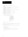
Terminate the Link
For proper operation, terminate both ends of a remote I/O link by using the
external resistors shipped with the programmable controller. Use either a
150W or 82W terminator.
If your remote I/O link:
Use this resistor rating:
operates at 230.4 kbps
82W
operates at 57.6 kbps or 115.2 kbps and no
devices listed in Table 2.A are on the link
2-8
The maximum number of The maximum number of
physical devices you
racks you can scan on
can connect on the link the link
32
16
Chapter 2
Installation
Use this resistor rating:
If your remote I/O link:
contains any device listed in Table 2.A
The maximum number of The maximum number of
physical devices you
racks you can scan on
can connect on the link
the link
16
150W
16
operates at 57.6 kbps or 115.2 kbps, and you do
not require the link to support more than 16
physical devices.
As shown in the table above, the terminators you use determine how many
devices you can connect on a single remote I/O link.
Table 2.A
I/O Link Devices that Require 150-W Termination Resistors
Device Type
Catalog Number
Series
Scanners
1771-SN
1 2 SD -SD2
1772-SD,
SD2
1775-SR
1775-S4A,
1775 S4A, -S4B
S4B
6008-SQH1, -SQH2
All
Adapters
1771-AS
Miscellaneous
1771-ASB
A
1771-AF
All
1771-DCM
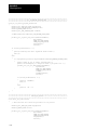
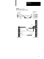
Figure 2.3
Terminating a Remote I/O Link Using a Resistor
PLC-5/VME processor or remote I/O adapter module
as the last device on an remote I/O link.
I/O adapter
To
Another I/O link device
Blue
Shield
Clear
Blue
Shield
Clear
Blue
Shield
Clear
1
2
150Ω
or
82Ω
19334
2-9
Chapter 2
Installation
Connecting an ExtendedLocal I/O Link
Use the extended-local I/O cables. These cables have a single-end
connector on one end and a dual-end connector on the other. The
maximum cable length for an extended-local I/O system is 30.5 cable-m
(100 cable-ft). Connect extended-local I/O adapters by using any of these
cables (Table 2.B):
Table 2.B
Standard Extended-Local I/O Cables
Cable Length:
Catalog Number:
1 m (3.3 ft)
1771-CX1
2 m (6.6 ft)
1771-CX2
5 m (16.5 ft)
1771-CX5
Important: You cannot connect or splice extended-local I/O cables to
form a custom cable length. For example, if you have a distance of four
meters between two extended-local I/O adapters or between a processor
and an extended-local I/O adapter, you cannot connect two 2-m cables
together. You would have to use the 5-m cable and have the extra meter
as slack.
You must set switches on the extended-local I/O adapter module. For
information, see its installation data, publication 1771-2.200.
2-10
Chapter 2
Installation
To make extended-local I/O connections, do the following:
!
PLC-5/V40L processor
ATTENTION: Turn off power to the extended-local
I/O adapter module before connecting or
disconnecting extended-local I/O cables.
Do not apply power to an I/O rack containing
an extended-local I/O adapter module until
all extended-local I/O cables are installed
and connected.
1. Connect the single-end connector to channel 2 of the processor.
2. Route the cable to the first extended-local I/O adapter.
3. Connect the dual-end connector to the extended-local I/O
adapter module. Be sure to screw in the retaining screws tightly.
4.
If the adapter:
Then:
is not the last one
on the link
1. Connect the single-end of a
local I/O network cable to the
exposed end connector on the
adapter module. Press and
hold the clips and snap to the
mating connector.
2. Route the cable to the next
adapter and connect the
dual-end connector to it.
is the last one
on the link
Terminate the link by installing the
local I/O terminator (1771-CXT) to
the exposed end of the dual-end
connector on the last adapter
module. The system will not run
without it. The terminator is included
with the processor.
!
ATTENTION: If you are not using any extended-local I/O
adapter modules, connect the extended-local I/O terminator,
1771-CXT, to channel 2 of the PLC-5/V40L processor to
ensure proper performance of the processor. This terminator is
included with your processor.
2-11
Chapter 2
Installation
Connecting a DH+ Link
Chan 1
Once you connect the programming device through a local DH+ link to
one processor, the device can communicate with any PLC-5/VME
processor on the link. You can also communicate with PLC-2, PLC-3, and
PLC-5/250 processors connected to the link provided you have the
appropriate programming software installed.
The processor has electrically parallel DH+ connectors.
Chan 1
1A
1A
1B
1B
This processor:
Has these electrically parallel DH+ connectors:
PLC-5/V40B
PLC-5/V80B
• 8-pin connector for each of channel 1A and 2A
• 3-pin connector on each of channel 1A and 2A
Channels 1A and 2A must be configured to support DH+ communication
to use the connectors described above. Note that Channel 1A’s default
configuration is DH+ communication.
Channels 1B and 2B can also support DH+ communication if properly
configured, but they do not have parallel connectors.
Chan 0
Chan 0
PLC-5/V40L
Chan 2
Chan 2
• 8-pin connector for channel 1A
• 3-pin connector for channel 1A
Channel 1A must be configured to support DH+ communication to use the
connectors described above. Note that Channel 1A’s default configuration
is DH+ communication.
Channel 1B can also support DH+ communication if properly configured,
but it does not have parallel connectors.
PLC-5/V40B
or -5/V80B
PLC-5/V40L
Use the Belden 9463 twinaxial cable (1770-CD) to connect the processor
to the DH+ link.
Follow these guidelines while installing DH+ communication links:
do not exceed these cable lengths:
- trunkline-cable length—3,048 m (10,000 cable-ft)
- drop-cable length—30.4 m (100 cable-ft)
do not connect more than 64 stations on a single DH+ link
2-12
Chapter 2
Installation
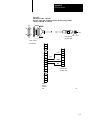
Use the 3-pin connector on the processor to connect a DH+ link.
The connector’s port must be configured to support a DH+
communication link.
Chan 0
You can connect a DH+ link two ways:
• trunkline/dropline—from the dropline to the connector screw
terminals on the DH+ connectors of the processor
• daisychain—to the connector screw terminals on the DH+
connectors of the processor
Chan 2
To make connections:
1. Connect the signal conductor with CLEAR insulation to the
3-pin connector terminal 1 at each end of each cable segment.
2. Connect the SHIELD drain wire to the 3-pin connector SH
terminal at both ends of each cable segment.
3. Connect the signal conductor with BLUE insulation to the 3-pin
connector terminal 2 at each end of each cable segment.
For more information, see the Data Highway/Data Highway
Plus/Data Highway II/Data Highway 485 Cable Installation Manual,
publication 1770-6.2.2.
Clear
Shield
Blue
82W resistor
PLC-5/V40B or -5/V80B
PLC-5/V40L
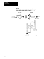
To connect a programming terminal via the 8-pin
connector on a PLC-5/VME processor on a DH+
link, use the following:
Communication card
to access a DH+ link
Cable
1784-PCMK
1784-PCM5 with a
1784-CP7 adapter
1784-KTX
1784-CP12 with a
1784-CP7 adapter
OR
1784-CP13 direct
connect to the front
of the PLC-5/VME
processor
8-pin
Mini-DIN
8-pin
Mini-DIN
1784-CP6
1784-CP6
Programming Terminal
2-13
Chapter 2
Installation
Connecting a Programming
Terminal to Channel 0
You can connect COM1 or COM2 from the programming terminal directly
to channel 0 on the PLC-5/VME processor. This serial port supports
RS-232C only.
You can configure channel 0 to either:
user mode—Configure channel 0 to user mode when you are connecting
it to RS-232 devices such as bar code readers, weigh scales, and
message displays. You can then communicate and manipulate
instructions through the ladder-logic ASCII read and write.
system mode—This is the default. Use this configuration when
connecting to programming operators interfaces (such as 6200 series
software and ControlView) using a built-in point-to-point protocol.
Although the communication is much like DH+ link, there is no access
to DH+ through Channel 0; therefore, the channel does not require a
DH+ station address. The default baud rate is 2400.
Figure 2.4
Programming Terminal to Channel 0 of a PLC-5/VME Processor
1784-T47 with 1784-KL/B
or IBM compatible
PLC-5/V40B
19541
You can use the following cables to connect to channel 0:
Table 2.C
Programming Terminal to Channel 0 Interconnect Cables
If you want to connect:
Use:
1784-T53 or IBM AT to channel 0
1784-CP10 or Cable #1
1784-T53 or IBM AT to channel 0 through a modem
Cable #6
1784-T47 or IBM XT to channel 0
1784-CP11 or Cable #2
1784-T47 or IBM AT to channel 0 through a modem
Cable #6
See Appendix E for more information on cable connections.
2-14
Chapter 2
Installation
Installing, Removing, and
Disposing of the Battery
If the processor is not powered, the processor battery retains processor
memory. The appropriate battery for your processor is shipped with the
processor and requires special handling. See Allen-Bradley Guidelines for
Lithium Battery Handling and Disposal, publication AG-5.4.
ATTENTION: Installing the battery requires handling the
processor, which can cause electrostatic discharge. See
Chapter 1 for details.
The battery indicator (BATT) warns you when the battery is low. The
indicator first lights when the processor has 10 days of battery back-up
power remaining. The LED will only light when the processor is powered.
Installing or Removing the Processor Battery
To install or remove the battery (cat. no. 1770-XYV), follow these steps:
1.
Remove the processor’s battery cover.
2.
Locate the battery.
3.
Install or remove the battery according to Figure 2.5.
Figure 2.5
Installing a Processor Battery (cat. no. 1770-XYV)
Make sure that the positive (+) side of
the battery is on the right hand side and
the negative (–) side of the battery is on
the left hand side.
Slide the battery into or out of
the processor.
19545
4.
Replace and secure the battery cover.
5.
Write the date that you installed the battery on the battery cover.
Important: You can insert or remove the battery without powering down
the processor. If you do not want to lose your program, make sure that the
processor is powered when replacing the battery.
2-15
Chapter 2
Installation
Disposing of the Battery
Refer to the Allen-Bradley Guidelines for Lithium Battery Handling and
Disposal, publication AG-5.4.
Do not dispose of lithium batteries in a general trash collection when their
combined weight is greater than or equal to 1/2 gram. A single 1770-XYV
battery contains .65 grams of lithium. Check your state and local
regulations that deal with the disposal of lithium batteries.
ATTENTION: Follow these precautions:
Do not incinerate or expose the battery to high temperatures.
Do not solder the battery or leads; the battery could explode.
Do not open, puncture, or crush the battery. The battery
could explode; and toxic, corrosive, and flammable
chemicals could be exposed.
Do not charge the battery. An explosion may result, or the
cell may overheat and cause burns.
Do not short positive and negative terminals together. The
battery will heat up.
2-16
Chapter
3
VMEbus Interface
Chapter Objectives
Read this chapter to understand the basic low-level interface to the
PLC-5/VME processor. The orientation of this chapter is based on a driver
program running on a separate CPU module communicating with
the processor.
Unless otherwise noted, all multiple-byte numerical fields are represented
in big-endian (Motorola) format, meaning that the most-significant data
byte appears in the lowest-addressed byte.
System Controller
You can configure the PLC-5/VME processor as a VMEbus system
controller by installing it in the left-most slot in the VME chassis. Its
system controller functions are limited, so this mode of operation is
intended for configurations where there is no more-capable CPU in
the system.
As a system controller, a PLC-5/VME processor is a single-level (SGL)
arbiter—it recognizes requests on level 3 only. In this mode, it also
generates the 16 MHz SYSCLK, begins the IACK daisy chain, and has a
bus timer. The bus timer timeouts any VMEbus transaction that asserts a
data strobe (DS0 or DS1) for longer than 93.75-125 microseconds. The
PLC-5/VME processor never asserts BCLR.
When it is not the system controller, you can configure the PLC-5/VME
processor to request the VMEbus on levels 3 or 1.
You select the system controller mode and bus request level by using
a switch (see page 2-3).
3-1
Chapter 3
VMEbus Interface
Bus-Release Modes
Two software-selectable bus-release modes are provided:
When set to:
The PLC-5/VME processor:
ROR
releases control of the VMEbus immediately after the current data-transfer
operation if it sees one of the bus-request lines asserted; otherwise it remains
“parked” on the bus.
RWD
once granted the bus, keeps ownership of the bus for the duration of a series of
contiguous data transfers (e.g., a copy operation), after which it relinquishes
control of the bus (i.e., does not stay parked on the bus).
There is one exception—when set to RWD, the PLC-5/VME processor
always relinquishes the bus after the current data-transfer operation
if BCLR is asserted. Thus, when used with a priority arbiter, the
PLC-5/VME processor honors higher-priority requests even when in
the midst of a contiguous copy in RWD mode. To configure your
system for this latter case, the PLC-5/VME processor must be using
bus-request level 1 and the separate system controller must be set to
priority arbitration.
VME LEDs
Three of the front-panel LEDs show VMEbus state information:
When this LED is lit:
It means that:
SYSFAIL
the PLC-5/VME processor is driving the VMEbus SYSFAIL signal.
master-access
the PLC-5/VME processor is performing a VMEbus cycle.
slave-access
a VMEbus master is performing an A24 slave access to the
PLC-5/VME processor.
Important: The PLC-5/VME processor does not respond to the VMEbus
SYSRESET signal if it is in a faulted state. In a faulted state, only a
power-on reset resets the processor.
3-2
Chapter 3
VMEbus Interface
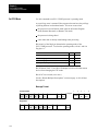
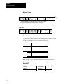
VME Signal Usage
Table 3.A shows the usage of the VMEbus signals on the P1 connector.
Table 3.A
VMEbus Signals on the P1 Connector
Pin
1
2
3
4
5
6
7
8
9
10
11
12
13
14
15
16
17
18
19
20
21
22
23
24
25
26
27
28
29
30
31
32
❶
Row A
Name
Use❷
D00
IO
D01
IO
D02
IO
D03
IO
D04
IO
D05
IO
D06
IO
D07
IO
GND
G
SYSCLK
O❸
GND
G
IO
DS1❶
❶
IO
DS0
IO
WRITE❶
GND
G
❶
IO
DTACK
GND
G
IO
AS❶
GND
G
IO
IACK❶
I
IACKIN❶
O
IACKOUT❶
AM4
IO
A07
IO
A06
IO
A05
IO
A04
IO
A03
IO
A02
IO
A01
IO
-12V
P
+5V
P
Row B
Name
BBSY❶
BCLR❶
ACFAIL❶
BG0IN❶
BG0OUT❶
BG1IN❶
BG1OUT❶
BG2IN❶
BG2OUT❶
BG3IN*❶
BG3OUT❶
BR0❶
BR1❶
BR2❶
BR3❶
AM0
AM1
AM2
AM3
GND
SERCLK
SERDAT❶
GND
IRQ7❶
IRQ6❶
IRQ5❶
IRQ4❶
IRQ3❶
IRQ2❶
IRQ1❶
+5VSTDBY
+5V
Use❷
IO
I
I
I
O❹
I
O
I
O❹
I
O
O
IO
IO
IO
IO
IO
G
G
IO
IO
IO
IO
IO
IO
IO
P
Row C
Name
Use❷
D08
IO
D09
IO
D10
IO
D11
IO
D12
IO
D13
IO
D14
IO
D15
IO
GND
G
IO
SYSFAIL❶
IO
BERR❶
IO
SYSRESET❶
❶
IO
LWORD
AM5
IO
A23
IO
A22
IO
A21
IO
A20
IO
A19
IO
A18
IO
A17
IO
A16
IO
A15
IO
A14
IO
A13
IO
A12
IO
A11
IO
A10
IO
A09
IO
A08
IO
+12V
P
+5V
P
indicates a low true signal.
❷ How the signal is used:
I = input; O = output; IO = input/output; P = power; G = ground;
blank = unused and unconnected
❸
❹
Only if the PLC-5/VME processor is configured as the slot-1 system controller. Otherwise logically
unconnected.
BG0OUT and BG2OUT are driven directly by the corresponding BGxIN*’s. This is done so that
you need not worry about the VMEbus backplane jumpers for the leftmost slot occupied by the
PLC-5/VME processor. You should not install the five bus-grant and IACK daisy-chain jumpers in
the leftmost slot.
3-3
Chapter 3
VMEbus Interface
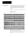
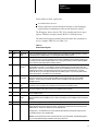
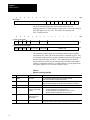
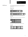
Configuration Registers
The configuration registers are a standard way of identifying, configuring,
controlling, and monitoring the PLC-5/VME processor as a VMEbus
device. They are mapped into the VMEbus A16 address space at a
location defined by switches 1-3 of SW2. For example, if these three
switches are set to ON, the first register (the ID register) is at address
FC00 (hex).
The registers are shown in Figure 3.1 and described individually thereafter.
Figure 3.1
The Eight Configuration Registers
offset
15
14
13
1
1
0
0
10
1
9
8
7
6
F
0
1
1
7
Device-Type Register
02
11
C
ID Register
00
12
5
4
3
2
E
1
1
1
1
F
1
1
1
1
1
1
1
SYSF
1
NOCV
1
1
SRIE
1
0
offset
0
0
01
0
0
03
C
1
0
1
1
E
1
1
8
1
0
1
1
RDY
1
1
0
Status/Control Register
04
GRE
1
RELM MYAS
PASS NOSF RSTP
05
Offset Register
06
1
SLAVE BASE
1
1
1
1
1
07
Command Control Register
08
WRDY LOCK ERR
1
COPY-TO-STATE COPY-FR-STATE
ERROR CODE
09
COPY-TO-STATE COPY-FR-STATE
ERROR CODE
0B
Command Control and Lock Register
0A
WRDY LOCK ERR
1
Command High Register
0D
0C
Command Low Register
0E
0F
Important: The system repeats these registers eight times; you can use
only the first eight registers as the configuration register.
These registers are described in detail below. Where a bit position has
been described as a 0 or 1, the bit is a read-only bit and writing to it has
no effect.
3-4
Chapter 3
VMEbus Interface
Unless otherwise noted, register bits:
are initialized to 0 at reset.
directly control the associated hardware function, so that changing a
register bit has an instantaneous effect on the function it controls.
The ID register, whose value is CFEC (hex), and the next (device-type)
register, 7FE8(hex), uniquely identify the PLC-5/VME processor.
The status/control register contains status and control bits, primarily for
use by a separate VME CPU (see Table 3.A).
Table 3.A
Status/Control Register
Bit
Register
Function
Definition
15
GRE
Global RAM
enable
If set by an application program (1), the PLC-5/VME processor is enabled as an VMEbus A24 slave. This bit is
not altered by the PLC-5/VME firmware. The 64K of global RAM is enabled by this bit.
12
SYSF
SYSFAIL
The PLC-5/VME processor drives the VME SYSFAIL line and the SYSFAIL LED on the front panel while this bit
is 0. This bit is set (to 1) by the PLC-5/VME processor firmware at initialization and not altered thereafter by the
PLC-5/VME processor unless a hardware failure occurs. One purpose of this bit is to allow a separate VMEbus
CPU to determine which VME module is asserting SYSFAIL.
10
NOCV
No check VME
status file
The VME status file, a file in the PLC-5/VME processor memory holds certain state information for compatibility
with the 6008-LTV processor. As in the 6008-LTV processor, ladder programs can modify certain parts of the
VME status file. If NOCV is 0, the PLC-5/VME processor checks its VME status file every scan loop to see if any
parameters have changed. This will increase your processor scan and communication time. You should
initialize this bit to 0 if you are changing the status file from a ladder program or if you are using 6200 software
from an external device. See Chapter 7 for more information.
7
SRIE
SYSRESET
input enable
If 1, VME SYSRESET causes a full hardware reset of the PLC-5/VME processor. If reset, VME SYSRESET is
ignored by the processor, except for resetting its VMEbus interface and terminating any current VMEbus
operations. This bit is reset by a hardware reset and set by PLC-5/VME processor firmware early in its
initialization process.
6
RELM
Bus release
mode
If 1, the bus release mode is ROR, otherwise it is RWD. This bit is not altered by the PLC-5/VME processor.
Bus release mode only applies to PLC-5/VME processor that behaves as a VMEbus master.
5
MYAS
My address
strobe
When 0, the PLC-5/VME processor is in the midst of VMEbus master transfer. This state bit is not intended for
use by other masters; it has meaning to only the PLC-5/VME processor’s firmware.
3
RDY
Ready
If 1, the PLC-5/VME processor is ready to accept commands. RDY and PASS are alerted at the same point by
the PLC-5/VME processor.
2
PASS
Self-test
passed
This bit is set by the PLC-5/VME processor after initialization if its self-test completes successfully. The bit is not
altered thereafter by the PLC-5/VME processor. If RDY=1 and PASS=0, the PLC-5/VME processor has failed its
self-test.
1
NOSF
SYSFAIL inhibit If 1, the PLC-5/VME processor cannot assert SYSFAIL. This bit is not altered by the PLC-5/VME processor
0
RSTP
Reset
If 1, the PLC-5/VME processor is in the reset state. During the reset state, the PLC-5/VME processor is inactive
and pending interrupts and bus requests are cleared. This register set is active and can be accessed by other
VMEbus devices. This bit is not altered by the PLC-5/VME firmware.
Changing it from 1 to 0 releases the PLC from its reset state and it follows its normal power sequence (if the
PLC-5/VME processor is not in a faulted state).
Attention: This bit causes the processor to reset and the I/O to stop communicating. Unpredictable operation
may occur with possible damage to equipment and/or injury to personnel.
3-5
Chapter 3
VMEbus Interface
15
14
Offset Register
13
12
11
10
9
8
SLAVE BASE
7
6
5
4
3
2
1
0
offset
1
1
1
1
1
1
1
1
07
The SLAVE-BASE field in the offset register defines the A24
mapping of the PLC-5/VME processor; register bits 15-8 are the values of
the VME address bits A23-A16. This field is not altered by the
PLC-5/VME processor.
15
14
13
12
11
10
9
8
7
6
5
4
3
2
1
0
offset
Command Control Register
WRDY LOCK ERR
1
COPY-TO-STATE COPY-FR-STATE
ERROR CODE
09
ERROR CODE
0B
Command Control and Lock Register
WRDY LOCK ERR
1
COPY-TO-STATE COPY-FR-STATE
The command-control register and command-control-and-lock register
contain state bits (Table 3.B) associated with the command register. They
are identical except how they read the command-control-and-lock register
and affect the state of the LOCK bit. The command-control-and-lock
register and the LOCK bit are provided to support multiple independent
senders of commands to the PLC-5/VME processor; you can ignore both
the register and the bit if you do not need this facility.
Table 3.B
Registers Containing State Bits
3-6
Bit
Register
Function
Definition
15
WRDY
Write ready
If 1, the command register is armed for an incoming command.
A write to the command-low register clears this bit.
14
LOCK
Command register lock
If 1, the command register has been locked.
If clear, the command register can be locked for the sending of a command.
13
ERR
Protocol error
If 1, a protocol error occurred associated with the last command received.
11-10
COPY-TO-STATE
The current state of the
continuous-copy-to-VME
operation
00
01
10
11
9-8
COPY-FROM-STATE The current state of the
continuous-copy-fromVME operation
Same encoding as above.
7-0
ERROR CODE
If ERR=1, this field is a code describing the error.
See specific requesting command types or Appendix D for a list of error codes.
Error code
None is enabled
Currently enabled and no errors encountered
Currently enabled but a noncatastrophic error has occurred
Shutdown because a catastrophic error has occurred
Chapter 3
VMEbus Interface
WRDY is used by another VMEbus master to determine whether or not the
PLC-5/VME processor is ready to receive a command. The VME master
processor should check that WRDY is set before it writes a command
value to the Command High/Command Low registers. This prevents the
VME master processor from accidentally overwriting a previously written
command.
The Command High/Command Low registers are a 1-deep FIFO. A
WRDY bit of 1 indicates that the command register FIFO is empty and that
the VME master processor may write a command value into the command
registers. Before the write cycle is completed, the processor hardware
clears the WRDY bit to indicate that the command register FIFO is full and
so that no other commands are sent. When the processor reads the FIFO to
process the command, the FIFO is emptied and the WRDY bit is
automatically set so that the processor can send a new command.
When a single PLC-5/VME processor is controlled by two or more master
processors, the LOCK bit acts as a semaphore to prevent the processor
from accidentally overwriting another processor’s commands.
A master processor attempts to get the LOCK bit by reading the
Command/Control/Lock register. If the LOCK bit is 0, that processor has
exclusive control. This is the only processor thats sees a LOCK bit value of
0; all other processors reading the Command/Control/Lock register see a
value of 1. The master processor executes its command and then clears the
LOCK bit in the Command/Control/Lock register so that another processor
can execute its command.
15
14
13
12
11
10
9
8
7
6
5
4
3
2
1
0
offset
Command High Register
0D
Command Low Register
0F
Commands
Commands are the primary form of communication from a separate
VMEbus CPU to the PLC-5/VME processor. A command is sent by
placing one of the following 32-bit values in the command registers.
31
24
23
0
000000001 Address of command block in VME A24 space
31
24
000000001
23
16 15
0
Addr of cmd blk in VME A16 space
3-7
Chapter 3
VMEbus Interface
If you designate:
The PLC-5/VME processor accesses the command block as an:
A24
A24 access with the 3D (standard supervisory data access) address modifier.
A16
A16 access with the 2D (short supervisory access) address modifier.
One exception in the situation where A24 is designated:
When you enable the PLC-5/VME processor’s slave memory and the
A24 address resides within the slave memory, the PLC-5/VME
processor accesses the memory locally. Every time the PLC-5/VME
processor is given an A24 address (e.g., of a command, within a
command), it determines whether or not the address falls within its
enabled slave memory. It does not take the implicit or explicit length of
the data item or structure into account.
Important: Data structures must be wholly within or without the
slave memory; data structures cannot be “half in and half out” of the
slave memory.
Also, the PLC-5/VME processor assumes it can do all master accesses to
commands as D16 and D08(EO). For data transfers, D16 versus D08(EO)
is programmable (to allow access to 8-bit I/O devices).
The diagram below shows the remainder of the command structure. The
message points to a command block, which identifies the type of
command. Some commands are wholly contained within the command
block. Others, specifically the PCCC commands, are contained in a
separate command packet. Such commands typically have data returned as
a reply; space for the reply packet is assumed to be allocated by the
sending VME CPU at the end of the command packet.
Address in command register
4 bytes
Command block
Command packet
32 bytes
Reply packet
4-248 bytes
4-248 bytes
The command-processing state of the PLC-5/VME processor can be
observed in several ways. After a command has been sent, readiness of the
command register indicates that processing of the previous command
has started.
Two ways are provided to detect completion of command processing.
The command block contains a response field into which a success or
error code is placed upon completion of the command. Optionally,
the PLC-5/VME processor can signal an interrupt at the end of
command processing.
3-8
Chapter 3
VMEbus Interface
The structure of the command block is shown below:
Word
15
14
13
12
11
10
9
8
7
0
Command word
1
Response word
6
2
5
4
3
2
1
0
Cmd interrupt level
3
Command interrupt status/ID
4
Command dependent
15
Word
Command
Description
0
Command word
Specifies the type of command and implicitly specifies whether there is an associated command packet.
1
Response word
The sender should set this to 0. PLC-5/VME processor stores a nonzero value in this word when
completion of command processing occurs. The value 00FF de-notes successful completion. Other
values are used for errors.
2
Command interrupt If nonzero, specifies that PLC-5/VME processor should generate a VMEbus interrupt immediately after
level
storing into the response word after command completion.
000 specifies no interrupt,
001 specifies interrupt level 1,
010 specifies level 2,
...,
111 specifies level 7.
3
Command interrupt The status/ID value returned during an interrupt-acknowledge cycle for the above interrupt.
status/ID
3-9
Chapter
4
Ladder-Program Interfaces
Chapter Objectives
Read this chapter to help you understand how to interact with the VMEbus
environment from your ladder program.
The PLC-5/VME processor allows ladder programs to perform direct
VMEbus read and write operations as well as to generate VMEbus
interrupts through the MSG instruction. This is the same data instruction
that is used for Data Highway, and it is programmed the same way. Four
messages are available:
Copy to VME
Copy from VME
Send VME interrupt
Check VME status file
Ladder Messages
To enter a VME message instruction, use your programming software to
edit the MSG control block. You will need to do the following:
specify a control block address for the MSG instruction
select ASCII as the message type
Important: You cannot use indirect addresses for the control-block
address in an MSG instruction.
enter channel 3A as the channel/port number
enter the appropriate VME command and accept the parameters you’ve
entered in the software
An internal processor interprets the ASCII string entered to determine the
VME operation to complete. The syntax for the ASCII strings is
as follows:
4-1
Chapter 4
Ladder-Program Interfaces
Table 4.A
Four Ladder Messages
Message
ASCII Syntax
Page
Copy to VME
CTV # X f : e vmeaddr width numelts
4-3
Copy from VME
CFV vmeaddr width # X f : e numelts
4-4
Send VME interrupt
SVI vmeint statid
4-5
Check VME status file
CSF
4-5
where:
X
is the file type.
File Type
f
Words per Element
counter
C
3
floating point
F
2
input
I
1
integer
N
1
output
O
1
control
R
3
status
S
1
timer
T
3
ASCII
A
1
BCD
D
1
is the file number—0 is the output image; 1 is the input
image; 2 is the status file; and 3-999 are any type except
input, output, and status files.
If the X file type is I, O, or S, the f parameter is optional.
4-2
e
is the element number—0-192 octal for I/O files, 0-127
decimal for the status file, 0-999 decimal for all other files.
vmeaddr
is the A16 or A24 VME address. A 6-character hexadecimal
number denotes an A24 address, which generates a 3D
address modifier. A 4-character hexadecimal number denotes
an A16 address, which generates a 2D address modifier on
the VMEbus.
Chapter 4
Ladder-Program Interfaces
width
is the width of VME transfers.
Width
Denotes
D16
16-bit transfers
D08
8-bit transfers (even/odd)
D08O
8-bit transfers (odd only)
D08B
8-bit transfers (even or odd depending on the starting VME address)
numelts
is the number of elements to be transferred (1-1000 decimal).
vmeint
is the VMEbus interrupt number (1-7).
statid
is the interrupt status/ID, a two-character hexadecimal
number given to the interrupt handler during the interrupt
acknowledge cycle.
You can use indirect addressing for the f and e parameters. Indirect
address format is:
Xf:e
where:
X, f, and e are as specified above, except that f and e cannot specify
indirect addresses.
Copy to VME
This message tells the processor to read the specified amount of data from
the specified file and write it using one or more VMEbus write operations.
As with the continuous-copy operations, if the address falls within the
enabled VMEbus slave memory of the PLC-5/VME processor, the data is
written into this dual-port memory directly without doing actual VMEbus
operations.
Example 1:
CTV #N8:10 A00000 D16 2
Example 1 reads elements 10 and 11 from file N8 and writes them in two
D16 writes to addresses A00000 and A00002 in the VME A24
address space.
4-3
Chapter 4
Ladder-Program Interfaces
Example 2:
CTV #N7:0 FF01 D08O 5
Example 2 reads the lower byte of elements 0 through 4 of file 7 and writes
them to addresses FF01 through FF09 (odd bytes only).
Data in PLC Processor
Result of Transfer to VMEbus
Address
Data (hex)
Address
Data
Address
N7:0
0044
FF00
00 44
FF01
N7:1
0055
FF02
00 55
FF03
N7:2
0066
FF04
00 66
FF05
N7:3
2077
FF06
00 77
FF07
N7:4
3088
FF08
00 88
FF09
Copy from VME
This message tells the PLC-5/VME processor to read the specified amount
of data from VMEbus memory using VMEbus read operations and write it
into the specified file. As with the continuous-copy operations, if the
address falls within the enabled VMEbus slave memory of the
PLC-5/VME processor, the data is read from this dual-port memory
directly without doing actual VMEbus operations.
Example 1:
CFV D004 D08 #N8:0 4
The example above performs eight D08 read operations beginning at VME
address D004 and then writes the data as four elements (0-3) in file N8.
Example 2:
CFV FF01 D08B #N7:0 3
Example 2 reads three consecutive bytes starting at FF01 in the VME A16
address space and writes the data into three elements in file N7:0.
Data on VMEbus
4-4
Result of Transfer to PLC Processor
Address
Data (hex)
Address
Data
Address
N7:0
0022
FF00
11 22
FF01
N7:1
0033
FF02
33 44
FF03
N7:2
0044
FF04
55 66
FF05
Chapter 4
Ladder-Program Interfaces
Send VME Interrupt
Tip
Your ladder program must clear the
Received field for a certain
interrupt level, located in word 24 of
the VME status file, so that the ladder
program can recognize another
interrupt at that level. The update field
in the VME status file must also be set
to one to reflect the fact that the VME
status file has changed and is ready to
receive new interrupt information.
This message tells the PLC-5/VME processor to assert a VMEbus
interrupt. When the interrupt handler replies with an interruptacknowledge cycle, the status/ID byte is returned to the interrupt handler.
For example:
SVI 2 F0
The example above asserts IRQ2 and gives status/ID value F0H to the
interrupt handler.
Check VME Status File
This message tells the PLC-5/VME processor to check the VME status file
for changes or to update the file with new VMEbus information. Before
executing this command, set bit 8 in element 28 of the VME status file if
you made changes to the file associated with the continuous-copy
configuration and you want the changes to take effect.
This command is needed when the NOCV bit of the status control register
is set.
For example:
CSF
If the NOCV flag in
the VME status/
control register is:
This message:
0
serves no useful purpose because the PLC-5/VME processor firmware
periodically checks the VME status file for changes (so that the
PLC-5/VME processor knows to update its internal state to reflect the
changes to the VME status file).
1
allows the ladder program to communicate changes to the PLC-5/VME
processor. An example of such a change would be the ladder program’s
modification of the interrupt mask in the VME status file.
4-5
Chapter 4
Ladder-Program Interfaces
Message Completion and
Status Bits
The PLC-5/VME processor manipulates only two of the status bits in the
control word of the internal message control block:
DN (done)
ER (error)
For the copy operations, DN is not set until and unless the data are
successfully transferred. If an error occurs, ER is set and an error code is
placed in the message control block.
For the SVI operation, DN is set if and when the interrupt-acknowledge
cycle is successfully performed by the interrupt handler. If the message
syntax is incorrect (interrupt is not 1-7 or status/ID is not two hexadecimal
digits), ER is set along with an error code. For the CSF operation, DN is
set immediately.
For unrecognizable messages, ER is set along with an error code. The
error codes are:
Code
Explanation
0000H
Success
0001H
Invalid ASCII message format
0002H
Invalid file type
0003H
invalid file number
0004H
Invalid file element
0005H
Invalid VME address
0006H
Invalid VME transfer width
0007H
Invalid number of elements requested for transfer
0008H
Invalid VME interrupt level
0009H
Invalid VME interrupt status-id value
000AH
VMEbus transfer error (bus error)
000BH
Unable to assert requested interrupt (already pending)
000CH
Raw data transfer setup error
000DH
Raw data transfer crash (PLC switched out of run mode)
000EH
Unknown message type (message type not ASCII)
If the PLC-5/VME processor receives the same message control block with
the same msg_address field from the processor core with the .TO (timeout)
bit set, the current operation is terminated.
4-6
Chapter 4
Ladder-Program Interfaces
VME Status File
The VME status file is a data file in the processor’s memory. It is used to
store VME setup and status information. It contains the setup information
for the continuous copy to/from VME. The VME status file number is
placed in word 15 of the PLC-5/VME status file. This file should be an
unused integer file. The PLC-5/VME processor accesses word 15 only at
initialization; thus any change of word 15 after initialization will have an
unpredictable effect.
Your programming software package should provide you with the
following types of capabilities:
monitor processor status
clear minor and major faults
monitor VME status
See your programming software documentation for specific information
about how to get to and use the software screens.
4-7
Chapter 4
Ladder-Program Interfaces
The following is the physical structure of the VME status file:
Word
15
14
13
12
11
10
9
8
7
6
5
4
3
2
0
ULA
SC
RELM
3
Reserved
SLE
4
5
6
SLADDRESS (HI BYTE)
SLADDRESS
FEN
FAM
FDS
FERROR
Reserved
7
8
FADDRESS (HI BYTE)
9
FADDRESS
10
FLENGTH
11
FFILE
FELEMENT
12
FINT
13
FSTATUSID
14
15
TEN
TAM
TDS
TERROR
16
17
Reserved
18
TADDRESS
19
TLENGTH
TADDRESS (HI BYTE)
20
TFILE
21
TELEMENT
TINT
22
23
24
TSTATUSID
IRQ7E IRQ6E IRQ5E IRQ4E IRQ3E IRQ2E IRQ1E
IRQ7R IRQ6R IRQ5R IRQ4R IRQ3R IRQ2R IRQ1R
25
IRQ2SID
IRQ1SID
26
IRQ4SID
IRQ3SID
27
IRQ6SID
IRQ5SID
28
29
UPDATED
IRQ7SID
Reserved
31
The fields are explained in Table 4.B. The fields marked in white are
read-only; they are for monitoring only and should not be overwritten.
4-8
0
VSYSF PSYSF
1
2
1
Chapter 4
Ladder-Program Interfaces
Table 4.B
Fields for the Physical Structure of the VME Status File
Word
Code
Function
Explanation
01
VSYSF
Describes the state of the VME
SYSFAIL signal. Read only.
If 0, SYSFAIL is being asserted (including by the PLC-5/VME processor);
if 1, SYSFAIL is not being asserted.
01
PSYSF
Read only
Describes the state of the VME SYSFAIL signal as being driven by the PLC-5/VME
processor. If 0, the PLC-5/VME processor is asserting SYSFAIL; if 1, it is not.
11
ULA
Unique logical address.
Read only.
The three-switch setting that determines the A16 base address of the PLC-5/VME
processor’s registers.
000 corresponds to FC00,
001 corresponds to FC40,
...,
111 corresponds to FFD0.
11
SC
System controller. Read only.
If 1, the PLC-5/VME processor has been configured as the VMEbus slot-1
system controller.
21
RELM
VMEbus release mode.
Read only.
If 0, the PLC-5/VME processor has been configured as RWD (release when done);
if 1, the PLC-5/VME processor has been configured as ROR (release on request).
41
SLE
Slave enable.
Read only.
If 1, the PLC-5/VME processor’s slave memory in the VMEbus A24 address space has
been enabled.
41
SLADDRESS
(HI BYTE)
Read only
Address bits 23-16 of the base address of the PLC-5/VME processor’s slave memory in
the VMEbus A24 address space.
51
SLADDRESS
Read only
Address bits 15-0 of the base address of the PLC-5/VME processor’s slave memory in the
VMEbus A24 address space.
1
PLC ladder logic cannot write to statsu file fields that reflect A16 configuration register settings; these fileds are read-only to ladder logic.
4-9
Chapter 4
Ladder-Program Interfaces
Continuous Copy
to/from VME
The PLC-5/VME can automatically read and write every ladder scan
to the the VMEbus without ladder-logic programming. You can configure
this function using your programming software or the ladder program
itself. See your programming software documentation for specific
information about where and how to configure this function in the
software.
Important: If you use ladder logic to make changes to your VME status
file, you must set word 28, bit 8 to 1 to apply the changes to your VME
processor.
You can only enable these operations when the PLC-5/VME processor is in
Run mode. You can specify up to 1000 words as the transfer length.
These words must be contiguous elements in files, but the transfer can span
files (see Figure 5.1).
The PLC-5/VME processor does not have the same programmable
synchronization control as the 6008-LTV processor.
The 6008-LTV processor allows:
copy transfer before or after the I/O update during housekeeping
transfer to be asynchronous or synchronous with the ladder scan
In other words, the ladder scan would keep going (regardless of whether
the VME transfer finished or not) rather than holding the ladder scan until
the transfer is complete.
The PLC-5/VME processor allows copying of data between the VMEbus
and the PLC-5/VME’s data table:
during the housekeeping of the ladder processor
concurrently with the I/O update.
The data coming from the VMEbus is buffered and comes from the
previous ladder scan. If the new data is not ready from the VMEbus, then
housekeeping is held up until the new data is available. The data going
from the PLC-5/VME to the VMEbus is transferred into VME during the
next ladder scan, just after housekeeping. There is a separate on-board
coprocessor that handles all VME transfers; and it is this processor that is
sending data to the VMEbus during the ladder scan.
You can read the processor’s input table. Because the transfer occurs
asynchronously with the I/O scan, however, values obtained from the input
table would likely be a mix of most recent values and values from the
previous scan cycle.
See Appendix A for examples of the commands and Chapter 7 for details
about performance and operation.
4-10
Chapter 4
Ladder-Program Interfaces
Error Codes
These are errors reported during the repeated continuous-copy operations
initiated by the continuous-copy-to-VME and continuous-copy-from-VME
commands. The existence of the error can be determined by examining the
copy-to-state and copy-from-state fields in the command control register.
The error code itself can be found in the VME status file.
VMEbus Interrupts
Code
Explanation
01H
VMEbus transfer error (VME bus error)
07H
Bad data address
FDH
Length specified as 0 or too large
FEH
Last end-of–opy interrupt not acknowledged
As well as being able to generate VMEbus interrupts, the PLC-5/VME
processor can receive interrupts generated by itself and other cards in the
system. You can enable or disable the function of receiving any or all of
the seven VME interrupt levels using your programming software.
See your programming software documentation set for information about
how and where to enable or disable this function.
Your ladder program must clear the Received field for a certain interrupt
level, located in word 24 of the VME status file, so that the ladder program
can recognize another interrupt at that level. The update field in the VME
status file must also be set to one to reflect the fact that the VME status file
has changed and is ready to receive new interrupt information.
4-11
Chapter 4
Ladder-Program Interfaces
The following is the physical structure of the VME operation
configuration file:
Word
15
14
13
12
11
10
9
8
7
6
5
4
3
2
0
ULA
SC
RELM
3
Reserved
SLE
4
5
6
SLADDRESS (HI BYTE)
SLADDRESS
FEN
FAM
FDS
FERROR
Reserved
7
8
FADDRESS (HI BYTE)
9
FADDRESS
10
FLENGTH
11
FFILE
FELEMENT
12
FINT
13
FSTATUSID
14
15
TEN
TAM
TDS
TERROR
16
17
Reserved
18
TADDRESS
19
TLENGTH
TADDRESS (HI BYTE)
20
TFILE
21
TELEMENT
TINT
22
23
24
TSTATUSID
IRQ7E IRQ6E IRQ5E IRQ4E IRQ3E IRQ2E IRQ1E
IRQ7R IRQ6R IRQ5R IRQ4R IRQ3R IRQ2R IRQ1R
25
IRQ2SID
IRQ1SID
26
IRQ4SID
IRQ3SID
27
IRQ6SID
IRQ5SID
28
29
UPDATED
IRQ7SID
Reserved
31
The fields are explained in Table 4.C. Fields marked read-only are for
monitoring only and should not be overwritten.
4-12
0
VSYSF PSYSF
1
2
1
Chapter 4
Ladder-Program Interfaces
Table 4.C
Fields for the Physical Structure of the VME Status File
Word
Code
Function
Explanation
62
FEN
From-VME enabled
If 1, the continuous-copy-from-VME operation is enabled (active when in run mode).
62
FAM
From-VME
address modifier
If 0, the continuous-copy-from-VME operation uses the 2D VMEbus address modifier (A16); if 1, it
uses 3D (A24).
62
FDS
From-VME data size
If 0, the continuous-copy-from-VME operation does D16 VMEbus transfers; if 1, it does D08(EO)
transfers.
62
FERROR
From-VME error code
If nonzero, refer to page 11 for the most-recent error.
82
FADDRESS (HI BYTE) Meaningful only if TAM=1
Address bits 23-16 of the address of the first byte of the VMEbus source.
92
FADDRESS
VMEbus source
Address bits 15-0 of the address of the first byte of the VMEbus source.
102
FLENGTH
From-VME copy length
The number of 16-bit words to be transferred by the continuous-copy-from-VME operation.
112
FFILE
From-VME file number
The number of the processor destination file of the continuous-copy-from-VME operation.
122
FELEMENT
From-VME
element number
The number of the first element to be transferred in the destination file of the continuous-copyfrom-VME operation.
132
FINT
From-VME interrupt
If nonzero, the VMEbus interrupt level of the interrupt to be generated after completion of each
continuous-copy-from-VME operation.
000 specifies no interrupt,
001 specifies interrupt level 1,
010 specifies level 2,
...,
111 specifies level 7.
142
FSTATUSID
From-VME status/ID
The VMEbus status/ID value transmitted during interrupt-acknowledge cycles of the
above interrupt.
152
TEN
To-VME enabled
If 1, the continuous-copy-to-VME operation is enabled (active when in run mode).
152
TAM
To-VME address modifier
If 0, the continuous-copy-to-VME operation uses the 2D VMEbus address modifier (A16);
if 1, it uses 3D (A24).
2
Both PLC ladder logic and the VME host computer can write to the status file fields that control the continuous-copy-from function. When both the ladder program and the host computer try to update the
status file simultaneously, the ladder program overwrites the changes made by the host.
4-13
Chapter 4
Ladder-Program Interfaces
Word
Code
Function
Explanation
153
TDS
To-VME data size
If 0, the continuous-copy-to-VME operation does D16 VMEbus transfers; if 1, it does D08(EO)
transfers.
153
TERROR
To-VME error code
If nonzero, refer to NO TAG for the most-recent error.
173
TADDRESS (HI BYTE) Meaningful only if TAM=1
Address bits 23-16 of the address of the first byte of the VMEbus destination .
183
TADDRESS
VMEbus destination
Address bits 15-0 of the address of the first byte of the VMEbus destination.
193
TLENGTH
To-VME copy length
The number of 16-bit words to be transferred by the continuous-copy-to-VME operation.
203
TFILE
To-VME file number
The number of the processor source file of the continuous-copy-to-VME operation.
213
TELEMENT
To-VME element number
The number of the first element to be transferred in the source file of the continuous-copy-toVME operation.
223
TINT
To-VME interrupt
If nonzero, the VMEbus interrupt level of the interrupt to be generated after completion of each
continuous copy to VME operation.
000 specifies no interrupt,
001 specifies interrupt level 1,
010 specifies level 2,
...,
111 specifies level 7.
233
3
TSTATUSID
To-VME status/ID
The VMEbus status/ID value transmitted during interrupt acknowledge cycles of the
above interrupt.
Both lPLC ladder logic and the VME host computer can write to the status file fields that control the continuous-copy-to function. When both the ladder program and the host computer try to update the
status file simultaneously, the ladder program overwrites the changes made by the host.
244
IRQxE
Interrupt x enabled
If bit x is 1, the PLC-5/VME processor is an interrupt handler for interrupt IRQx. If IRQx is
asserted, the PLC-5/VME processor will perform a VMEbus interrupt acknowledge cycle, store the
interrupt status/ID received in IRQxSID, and set bit IRQxR.
244
IRQxR
Interrupt x received
If bit x is 1, the PLC-5/VME processor has accepted a VMEbus interrupt for IRQx since bit IRQxR
was last 0.
4
For bits 8 through 15, Both PLC ladder logic and the VME host computer can write to the VME IRQ status file field. When both the ladder program and the host computer try to update the status file
simultaneously, the ladder program overwrites the changes made by the host. If a given IRQxE flag is set to 0, then the corresponding IRQxR and IRQxSID flags are also cleared to 0.If a given IRQxE flag
is set and a VME interrupt is received on the corresponding level, then the corresponding IRQxR flag is set and the corresponding IRQxSID field is loaded with 8-bit status ID that the interruptor returns.To
clear the IRQxR and IRQxSID fields, write a non-zero value into the VSF Updated field with your ladder program. This clears all IRQxR bits and IRQxSID fields.If more than one interrupt arrives on a given
level before the ladder program clears the IRQxR/IRQxSID fields, the corresponding IRQxR bit remains set and the IRQxSID field contains the SID from the last interrupt received.If any interrupts are
pending when the VME status file update byte is set, the IRQxR/IRQxSID fields are cleared and the interrupts discarded. Subsequent interrupts are handled as described above.
Status file contents are preserved across a power cycle or SYSRESET except in the following conditions:
-If a change is made to A16 configuration registers or board jumpers (i.e. system controller, bus grant level, ULA, etc.), the changes are reflected in words 0-5 of the status file.
-The IRQxR and IRQxSID fields are initially set to 0. When you cycle or reset power to the hardware, any interrupts that were pending become meaningless.
When you set the NOCV bit in the status and control register, continuous updating of the status file is disabled. Therefore, the coprocessor continues to execute continuous copies and handle VME
interrupts according to the last status file settings you made – the last time you set the NOCV bit or sent a CSF ladder message. Any changes that the ladder program makes to the status file are not
forwarded to the coprocessor until you send a CSF message or clear the NOCV bit. Similarly, VME interrupts are not flagged in the status file until you clear the NOCV bit or send a CSF message.
25-27
IRQxSID
Interrupt x status/ID
If IRQxR is 1, this field is the VMEbus status/ID received from the interrupt acknowledge cycle.
Read only.
28
UPDATED
Accept status file changes
Unless bit NOCV is 1 in the VMEbus status/control register, the PLC-5/VME processor reads this
field every scan cycle as an indication of whether anything in the VME status file has changed. A
nonzero value denotes a change, in which case the PLC-5/VME processor determines the whole
status file for changes, records them as internal state, and stores zero in the UPDATED field. If a
ladder program or an external programming terminal changes the status file, it should put a
nonzero value in this field after making all the other needed changes to the status file.
4-14
Chapter
5
Commands
Chapter Objectives
Read this chapter to understand the command interface to the PLC-5/VME
processor. The orientation of this chapter is based on a driver program
running on a separate CPU module communicating with the processor.
Unless otherwise noted, all multiple-byte numerical fields are represented
in big-endian (Motorola) format, meaning that the most-significant data
byte appears in the lowest-addressed byte.
Command Types
There are four types of commands:
Command
Command
Word
Definition
Continuous Copy
to VME
0001H
Instructs the PLC-5/VME processor to copy processor file
memory to VMEbus memory once per scan cycle of the
processor.
It is similar in definition to the corresponding command in the
6008-LTV processor.
Continuous Copy
from VME
0002H
Instructs the PLC-5/VME processor to copy VMEbus memory
to the processor file memory once per scan cycle.
Handle Interrupts
0003H
Defines which VMEbus interrupts the PLC-5/VME processor
behaves as an interrupt handler.
Send PCCC
FFFFH
Sends a command packet containing a standard PCCC.
These were referred to as “selective” commands in the
6008-LTV processor.
5-1
Chapter 5
Commands
Continuous-Copy
Commands
The command:
Has the
value of:
Configures the PLC-5/VME processor to
copy a block of data:
Continuous copy to VME
0001
from its data table during each ladder scan.
Continuous copy from VME
0002
into its data table during each ladder scan.
See Appendix A for a sample implementation of this command.
You can only enable these operations when the PLC-5/VME processor is in
Run mode. You can specify up to 1000 words as the transfer length.
These words must be contiguous elements in files, but the transfer can span
files (Figure 5.1).
Figure 5.1
Continuous-Copy Command Structure
Word
15
14
13
12
11
10
9
7
0
Command word
1
Response word
2
Reserved
Reserved
5
6
3
2
1
0
Reserved
Enable
Width
8
Data address (high)
9
Data address (low)
Address modifier
Data size
10
11
Data table file number
12
Element number
Reserved
13
15
4
Command interrupt status/ID
Reserved
14
5
Cmd interrupt level
4
7
6
Reserved
3
5-2
8
Op interrupt level
Reserved
Op status/ID
Reserved
Chapter 5
Commands
Word
Command
Description
0
Command word
Has value 0001H (to VME) or 0002H (from VME).
1
Response word
As defined previously for all commands in common. See page 3-9.
2
Command interrupt level
As defined previously for all commands in common. See page 3-9.
3
Command interrupt status/ID
As defined previously for all commands in common. See page 3-9.
7
Enable
If 0, none of the subsequent fields are interpreted and the currently defined copy-to-VME (or from-VME)
operation is disabled. If 1, this command establishes a new copy-to-VME or copy-from-VME operation.
7
Width
This defines the data width used to perform reads and writes to VME for the copy operations.
0 denotes D16 and 1 denotes D08(EO).
7
Address modifier
This defines the address space in which the VME data are accessed. Only two values are valid: 2D (A16)
and 3D (A24 or data falls in PLC-5/VME processor’s slave memory).
8-9
Data address
This specifies the VME address at which data transfer is to begin. Bits 23-16 of the A24 VME address are in
bits 7-0 of word 8, and bits 15-0 of the VME address are in word 9. If A16 is specified, word 8 is unused and
word 7 contains the A16 address.
If the PLC-5/VME processor’s slave memory is enabled, if A24 is specified, and if this address falls into
where the slave memory is mapped, the data is transferred into the slave memory without performing any
VMEbus accesses. Otherwise, the PLC-5/VME processor does the transfer as a VMEbus master.
10
Data size
This specifies the number of 16-bit words to be transferred.
11
Data table file number
This specifies the file number of the PLC-5/VME processor’s data table file to or from which data is to
be transferred.
12
Element number
This specifies the element number in the data table file at which the transfer is to begin.
13
Op interrupt level
If nonzero, specifies the VMEbus interrupt to be generated upon completion of each copy operation.
000 specifies no interrupt,
001 specifies interrupt level 1,
010 specifies level 2,
...,
111 specifies level 7.
14
Op status/ID
If an end-of-each-copy interrupt is specified in the previous field, this field is the status/ID value returned by
the PLC-5/VME processor as a result of the corresponding interrupt-acknowledge cycle.
Notes on Copy Operations
For convenience of checking by the driver program, the on-going state
of continuous copy is described in the command control register (see
Chapter 3, page 3-6). If this indicates that an error has occurred, the
driver reads the VME status file (via a PCCC command) to obtain the
specific error code.
To change the copy parameters—i.e., to establish a different continuous
copy—in the PLC-5/VME processor, the driver must issue another
command to set bit 8 of element 28 in the VME status file using a PCCC
write operation.
5-3
Chapter 5
Commands
Copy Synchronization
The PLC-5/VME processor does not have the same programmable
synchronization control as does the 6008-LTV processor.
The 6008-LTV processor allows the copy transfer to:
happen before or after the I/O update during housekeeping
be asynchronous or synchronous with the ladder scan
In other words, the ladder scan would keep going (regardless of whether
the VME transfer finished or not) rather than holding until the transfer
is complete.
The PLC-5/VME processor allows the copying of data between the
VMEbus and the PLC-5/VME’s data table:
during the housekeeping of the ladder processor
concurrently with the I/O update
The data coming from the VMEbus is buffered and was collected during
the previous ladder scan. If the new data is not ready from the VMEbus,
the housekeeping is held up until the new data is available. The data going
from the PLC-5/VME to the VMEbus is transferred into VME during the
next ladder scan, just after housekeeping. There is a separate on-board
coprocessor that handles all VME transfers; and it is this processor that is
sending data to the VMEbus during the ladder scan.
You can read the processor’s input table. Because the transfer occurs
asynchronously with the I/O scan, however, values obtained from the input
table would likely be a mix of most recent values and values from the
previous scan cycle.
See Appendix A for examples of the commands and Chapter 7 for details
about performance and operation.
Error Codes
These are errors reported during the repeated continuous-copy operations
initiated by the continuous-copy-to-VME and continuous-copy-from-VME
commands. The existence of the error can be determined by examining the
copy-to-state and copy-from-state fields in the command control register.
The error code itself can be found in the VME status file.
5-4
Chapter 5
Commands
Table 5.A
Error Codes
Handle-Interrupts Command
Code
Explanation
01H
VMEbus transfer error (VMEbus bus error)
07H
Bad data address
09H
Past end of data file
FDH
Length specified as 0 or too large
FEH
Last end-of-copy interrupt not acknowledged
This command, whose command word has the value 0003, defines the
VME interrupts to be handled by the PLC-5/VME processor (Figure 5.2).
Figure 5.2
Handle-Interrupts Command Structure
Word
15
14
13
12
11
10
9
8
7
0
Command word
1
Response word
2
Reserved
4
3
2
1
0
Command interrupt status/ID
4
Reserved
5
6
Reserved
7
5
Cmd interrupt level
Reserved
3
6
Reserved
Reserved
Enable
8
Reserved
12
13
Op interrupt level
Reserved
14
Reserved
15
Reserved
See Appendix A for a sample implementation of this command.
5-5
Chapter 5
Commands
Word
Command
Description
0
Command word
Has value 0003H
1
Response word
As defined previously for all commands in common, see page 3-9.
2
Command interrupt level
As defined previously for all commands in common, see page 3-9.
3
Command interrupt status/ID
As defined previously for all commands in common, see page 3-9.
7
Enable
If 0, handling of the specified interrupt (op interrupt level) is disabled.
If 1, handling of the specified interrupt is enabled.
13
Op interrupt level
Specifies the VMEbus interrupt whose handling is to be enabled or disabled.
000 specifies no interrupt,
001 specifies interrupt level 1,
010 specifies level 2,
...,
111 specifies level 7.
When you enable an interrupt, the PLC-5/VME processor detects this
interrupt on the VMEbus, performs an 8-bit interrupt-acknowledge cycle,
and reads an 8-bit status/ID from the interrupter. The interrupt and
status/ID is then posted in the VME status file for accessibility to the
ladder program.
This mechanism allows VME interrupts to make a mark in the VME status
file in the processor. The ladder program can test this element in the status
file to determine whether or not the interrupt has occurred. This essentially
converts interrupts to polled events from the point of view of the ladder
program and thus introduces some small fixed overhead to the scan time;
but it gives the ladder program considerable flexibility in determining the
interrupt latency. For example, the ladder program can test for the
interrupt each scan, multiple times each scan (for smaller latency), or every
N scans.
5-6
Chapter 5
Commands
Send-PCCC Command
This command, whose command word has the value FFFF, sends an
Allen-Bradley Programmable Controller Communications Command. In
the 6008-LTV processor, this was known as the “selective command.”
See Appendix A for a sample implementation of this command.
Figure 5.3
Send-PCCC Command Structure
Word
15
14
13
12
11
10
9
8
7
0
Command word
1
Response word
2
6
5
4
3
1
0
Cmd interrupt level
Reserved
3
2
Reserved
Command interrupt status/ID
4
Reserved
6
Width
7
8
Packet address (high)
9
Packet address (low)
10
Packet size
Address modifier
11
Reserved
15
Word
Command
Description
0
Command word
Has value FFFFH
1
Response word
2
Command interrupt level
As defined previouslyy for all commands in common. Note that command completion is defined
as th
the point
i t where
h th
the PLC
PLC-5/VME
5/VME processor hhas processedd th
the PCCC commandd andd fformedd
the reply
re ly packet.
acket.
3
Command interrupt status/ID
7
Width
This defines the data width used to perform VME accesses to the packet.
0 denotes D16 and 1 denotes D08(EO).
7
Address modifier
This defines the address space in which the packet is accessed.
Only two values are valid: 2D (A16) and 3D (A24 or data falls in PLC-5/VME processor’s
slave memory)
8-9
Packet address
This specifies the VME address at which the PCCC command packet begins. Bits 23-16 of
the A24 VME address are in bits 7-0 of word 8, and bits 15-0 of the VME address are in
word 9.
If the PLC-5/VME processor’s slave memory is enabled and if this address falls into where
the slave memory is mapped, the data is transferred into the slave memory without performing
any VMEbus accesses. Otherwise, the PLC-5/VME processor does the transfer as a
VMEbus master.
10
Packet size
The size of the PCCC command packet in bytes.
5-7
Chapter 5
Commands
Command-Protocol
Error Codes
Response-Word
Error Codes
5-8
These are the command-protocol codes placed in the error-code field of the
command-control register when the ERR bit is 1.
Code
Explanation
00H
No error
01H
Invalid value in command register
02H
Cannot access first word of command block (usually a VMEbus bus error)
03H
Cannot access other than first word of command block
04H
Cannot write response word in command block
These are errors reported in the response word of the command block
when the command cannot be carried out successfully. The even byte of
the response word describes the type of error and the odd byte describes
the time or situation of occurrence.
Code
Explanation
00FFH
Command successfully completed
0200H
Bad address modifier in command block
0300H
Bad VME address in command block
0400H
Bad command word (word 0)
0500H
Bad data/packet size (word 10)
0600H
Local PCCC queue overflow; PCCC not processed
8000H
VMEbus error
6
Chapter
PLC-5/VME Processor Communications
Commands
Chapter Objectives
Read this chapter to understand the function of the extended PCCCs in the
PLC-5/VME processor.
Important: Numerical data in the extended PCCCs is defined in
little-endian (Intel) format.
See the Data Highway / Data Highway Plus / DH-485 Communication
Protocol and Command Set reference manual, publication number
1770-6.5.16, for more information on PCCC commands.
PCCC Structure
PCCCs are transferred in a command packet attached to a send-PCCC
command. When the PLC-5/VME processor has finished processing the
PCCC, a reply is returned by appending a reply packet to the PCCC
command packet.
A PCCC command packet has the following format:
Bit
7
0
1
2
3
Byte 4
5
6
7
8
9
0
6
0
5
4
3
2
1
0
Reserved (DST)
Reserved (PSN)
Reserved (SRC)
Reserved (PSN)
0
0
COMMAND
Reserved
TNS – first byte
TNS – second byte
FUNCTION CODE (FNC)
OPTIONAL DATA
(up to 243 bytes)
Command
Description
First four words
Currently unused and unexamined. To assure compatibility with any future
use of these bytes, they should be initialized to 0. DST, PSN and SRC are
included for reference only.
COMMAND
Specifies the PCCC command type.
TNS
Transaction or sequence word. A value that is copied into the reply packet
to associate commands with replies. There cannot be more than one PCCC
active in the PLC-5/VME processor with the same TNS from any source.
FUNCTION CODE
This is an extension of the COMMAND field.
OPTIONAL DATA
The value(s) and size of this field are specific to the type of command.
6-1
Chapter 6
PLC-5/VME Processor
Communications Commands
A PCCC reply packet has the following format:
Bit
7
0
1
2
3
4
Byte 5
6
7
8
9
10
11
11/12
6
5
4
3
2
1
0
LNH - first byte
LNH - second byte
Reserved (DST)
Reserved (PSN)
Reserved (SRC)
Reserved (PSN)
0
1
0
0
COMMAND
REMOTE ERROR
0
TNS – first byte
TNS – second byte
OPTIONAL EXTENDED STATUS (EXT STS)
OPTIONAL DATA
(up to 243 bytes)
Command
Description
LNH
Length of the optional portion of the reply packet in bytes. The first byte
of LNH is the high-order byte (actual length = LNH – 4).1
COMMAND
Copied from the associated command packet.
REMOTE ERROR
If nonzero, the PLC-5/VME processor has encountered a problem
attempting to process the command. 0001-1110 represent error codes
listed separately. 1111 indicates that the EXT STS field contains an error
code.
TNS
Copied from the associated command packet.
OPTIONAL
EXTENDED STATUS
This field contains an error code when the REMOTE-ERROR field has
the value 1111.
OPTIONAL DATA
This contains data returned as part of the reply. The value(s) and size of
this field are specific to the type of command. Whether this field starts at
offset 10 or offset 11 depends on whether the specified command is
defined to return the extended status byte.
1
As we stated early in this chapter, all numerical data in the extended PCCCs is defined in Intel format,
however, this is the exception. This is in the Motorola format.
The host CPU driver program is responsible for leaving sufficient space for
the reply packet immediately after the command packet in memory. The
actual size of the reply packet depends on the specific type of
PCCC command.
6-2
Chapter 6
PLC-5/VME Processor
Communications Commands
Supported PCCCs
All PCCCs supported by the PLC-5 processor are supported by the
PLC-5/VME processor. Since only a subset are useful to driver programs,
only the useful subset and the PCCCs compatible with the “selective
commands” of the 6008-LTV processor are described here.
PCCC Name
6008-LTV Processor
(Equivalent Name)
Command FNC
Page
Sample
Echo
Echo
06H
00H
6-5
B-59
Identify host and status
Identify PLC-5/VME
processor, report status
06
03
6-6
B-67
Read-modify-write
Write bit
0F
26
6-8
B-76
Typed read
Read block
0F
68
6-10
Typed write
Write block
0F
67
6-18
Set CPU mode
Set processor mode
0F
3A
6-20
B-84
Upload all requests
Set upload privilege
0F
53
6-21
B-87
Download all requests
Set download privilege
0F
50
6-23
B-53
Upload complete
Restart after upload
0F
55
6-24
B-50
Download complete
Restart after download
0F
52
6-25
B-56
Read bytes physical
Physical read
0F
17
6-26
B-70
Write bytes physical
Physical write
0F
18
6-27
B-44
Get edit resource
0F
11
6-29
B-62
Return edit resource
0F
12
6-30
B-73
Apply port configuration
0F
8F
6-31
B-47
Restore port configuration
0F
90
6-32
B-81
Status codes returned in the reply packet are not defined for each PCCC,
but they are listed together in a subsequent section.
Some PCCCs require the specification of a system address as part of the
data. PCCCs support different formats of system addresses, but the only
form described in this manual is a binary memory address of something in
the file storage of the processor. The form recommended is compatible
with the form used in the 6008-LTV processor. Thus, the term “system
address” in the context of the following command descriptions is the
following seven-byte value.
06
FF
file number
FF
element number
For instance, the 7-byte system address 06 FF 01 00 FF 02 01 specifies
element 258 (0102h) in file 1 (0001h).
6-3
Chapter 6
PLC-5/VME Processor
Communications Commands
Header Bit/Byte
Descriptions
Table 6.A describes the bytes that compose the headers of command and
reply packets. We do not repeat their descriptions in the description of
each command that follows.
Important: All numbers are decimal except where noted by an “H”
for Hexadecimal.
Table 6.A
Command and Reply Packets
Header Bytes
Function
Description
CMD
Command
CMD and FNC bytes together define the command to be
executed. Command codes are included in command
descriptions later in this chapter.
STS
Status
If the PLC-5/VME processor detects an error, it reports error
codes in the reply packet. Zero means no error. Error codes are
described for each command, below.
Set to zero in the command packet.
STS and EXT STS (extended status) are returned in the reply
packet in response to some commands. STS bits 07-00 contain
the value F0H when reporting extended status. Status and
extended status codes that could be returned in the reply packet
are described for each command, below.
TNS
Transaction
code (two
bytes)
The host CPU’s driver program should generate a unique 16-bit
number for each transaction so that it can match replies to
corresponding commands. There should not be more than one
active packet with the same transaction number from any source.
Whenever the PLC-5/VME processor receives a command, it
copies the TNS value of the command packet into the same field
of the corresponding reply packet without changing the TNS
value.
FNC
Function
code
For a command packet, it combines with the CMD byte to define
the command. See CMD, above.
EXT STS
Extended
status code
If the PLC-5/VME processor detects an error, it reports extended
status codes in the reply packets of some commands. See
STS, above.
The reply packet also contains the CMD byte. The PLC-5/VME processor
copies the CMD value from the command packet into the corresponding
reply packet.
6-4
Bit
Description
07
Always zero
06
Designates command or response. The host CPU resets this bit when sending a
command. The PLC-5/VME processor sets this bit to 1 when sending a reply. (0 =
command, 1 = reply)
05, 04
Not used (set to zero)
03-00
Command codes (in Hex)
Use command codes with function codes FNC to specify the type of command.
Chapter 6
PLC-5/VME Processor
Communications Commands
Echo
Use this command to debug or test PCCC transmission capability. The
command packet can contain up to 243 bytes of data. The processor
simply returns (“echos”) the same data in the reply packet.
Message Format
Command Packet
DST
00
PSN
00
SRC
00
PSN
00
CMD
06
STS
00
DST
00
PSN
00
SRC
00
PSN
00
TNS
FNC
00
DATA
up to 243 bytes
Reply Packet
LNH
Hi
LNH
Lo
CMD
46H
STS
TNS
SAME DATA
up to 243 bytes
Error Codes
Extended status codes are reported in the response packet. The STS byte
contains 00H if no error, F0H when the PLC-5/VME processor detects an
error. If an error, the error code is indicated in the EXT STS byte
as follows:
STS
EXT STS
Description
00H
–
F0H
10H
Illegal command or format
20H
Host has a problem and will not communicate
30H
Remote station host is missing, disconnected, or shut down
40H
Host could not complete function due to hardware fault
50H
Addressing problem or memory protect rungs
60H
Function disallowed due to command protection selection
80H
Compatibility mode file missing or communication zone problem
90H
Remote station cannot buffer command
B0H
Remote station problem due to download
No error
Refer to page D-3 for additional information on PCCC status codes.
Sample API Module
For a sample
interface
header file:
P40VECHO.H
Refer to page:
B-58
For a sample
implementation
source file:
P40VECHO.C
Refer to page:
B-59
6-5
Chapter 6
PLC-5/VME Processor
Communications Commands
Identify Host and Status
Use this command to:
diagnostic command when debugging your host CPU’s driver program
confirm communication with the specified PLC-5/VME processor
identify its operating mode
report other useful information before initiating an upload or download
Message Format
Command Packet
DST
00
PSN
00
SRC
00
PSN
00
CMD
06
STS
00
DST
00
PSN
00
SRC
00
PSN
00
TNS
FNC
03
Reply Packet
LNH
Hi
LNH
Lo
CMD
46H
STS
TNS
STATUS (36 bytes)
See the “Header Bit/Byte Descriptions” section on page 6-4 for
descriptions of all bytes except the table on the next page.
The STATUS field returned in the reply packet indicates the following:
Byte
Description
1
Operating status of the PLC-5/VME processor
Bits 2-0
000 = program load
100 = remote program load
110 = remote run
010 = run mode
101 = remote test
001, 011, 111 = not used
Bit 3
0 = no fault
1 = major fault
Bit 4
0 = not downloading
1 = download mode
Bit 5
0 = not uploading
1 = upload mode
Bit 6
0 = not testing edits
1 = testing edits
Bit 7
0 = no edits in PLC-5/VME processor
2
EBH
PLC-5/VME processor
3
38H
Processor expansion type
4-7
Processor Memory Size (96K bytes) (low word, low byte first)
8
Series and revision of PLC-5/VME processor
9
6-6
1 = edits in processor
Bits 4-0
00000 = Revision A
00001 = Revision B, etc.
Bits 7-5
000 = Series A
001 = Series B, etc.
Processor station number
Bits 5-0
Station number 0-63
10
FDH
Future development
11
00H
Future development
Chapter 6
PLC-5/VME Processor
Communications Commands
Byte
Description
12,13
Number of data files used (highest assigned file number + 1) (low byte first)
14, 15
Number of program files used (highest assigned file number + 1) (low byte first)
16
Forcing status
Bit 0
0 = no forces active
1 = forces active
Bit 4
0 = no forces present
1 = forces present
0 = memory not protected
any bit set = memory is protected
0 = RAM valid
any bit set = invalid RAM
All other bits = 0
17
Memory protect
Bits 7-0
18
RAM invalid
Bits 7-0
19
Debug mode (non zero means Debug mode is on)
20, 21
Hold point file (low byte first) if Debug mode is on
22, 23
Hold point element (low byte first) if Debug mode is on
24, 25
Edit time stamp seconds (low byte first)
26, 27
Edit time stamp minute (low byte first)
28, 29
Edit time stamp hour (low byte first)
30, 31
Edit time stamp day (low byte first)
32, 33
Edit time stamp month (low byte first)
34, 35
Edit time stamp year (low byte first)
36
Port number this command received on (10H = port 1A, 11H = port 1B, 20H = port
2A, 21H = port 2B, 30H = port 3A, )
Error Codes
Extended status codes are reported in the response packet. The STS byte
contains 00H if no error, F0H when the PLC-5/VME processor detects an
error. If an error, the error code is indicated in the EXT STS byte
as follows:
STS
EXT STS
Description
00H
–
F0H
10H
Illegal command or format
20H
Host has a problem and will not communicate
30H
Remote station host is missing, disconnected, or shut down
40H
Host could not complete function due to hardware fault
50H
Addressing problem or memory protect rungs
60H
Function disallowed due to command protection selection
80H
Compatibility mode file missing or communication zone problem
90H
Remote station cannot buffer command
B0H
Remote station problem due to download
No error
6-7
Chapter 6
PLC-5/VME Processor
Communications Commands
Refer to page D-3 for additional information on PCCC status codes.
Sample API Module
For a sample
interface
header file:
Refer to page:
P40VIHAS.H
Read-Modify-Write
For a sample
implementation
source file:
B-64
P40VIHAS.C
Refer to page:
B-67
Use this command to set or reset specified bits in specified words of data
table memory. The command tells the PLC-5/VME processor to apply a
read-modify-write cycle to:
read out the data
apply an AND mask
apply an OR mask
return the results to the specified address
The address/mask field (up to 242 bytes) in the command packet contains
multiple blocks, each of which contains an PLC-5/VME processor file
address, a 2-byte AND mask, and a 2-byte OR mask.
Read-Modify-Write changes bits in one or more elements in the
processor’s memory. The data field in the command contains up to 242
bytes of address/OR/AND mask field. For each element specified, the
processor reads a 16-bit word, ANDs it with the AND mask, ORs it with
the OR mask, and writes the result back into the location in the
processor memory.
An address/OR/AND mask field is an 11-byte value defined as:
System address
OR mask
AND mask
7
2
2
As an example, 06 FF 02 00 FF 03 00 00 00 00 00 clears (zeroes) the word
at element 3 in file 2.
Important: The controller may change the states of the original bits in
memory before this command can write the word back to memory.
Therefore, some data bits may unintentionally be overwritten. To help
prevent this, we suggest that you use this command to write into the
storage area of a programmable controller’s data table, and have the
controller read the word only, not control it.
6-8
Chapter 6
PLC-5/VME Processor
Communications Commands
See the “Header Bit/Byte Descriptions” section on page 6-4 for
descriptions of all bytes except the following:
Use the:
To specify:
PLC-5/VME processor the address of the element(s) to be modified. You can use the 242-byte
ADDR field
address/mask field to modify selected words in and between data files.
AND mask (2-bytes
field)
which bits are reset to 0 in the addressed word. A 0 in the AND mask
resets the corresponding bit in the addressed word to 0. A 1 in the AND
mask leaves the corresponds bit unchanged. Low byte comes first in the
AND mask.
OR mask
(2-byte field)
which bits to set to 1 in the addressed word. A 1 in the OR mask sets to 1
the corresponding bit the addressed word. A 0 in the OR mask leaves the
corresponding bit unchanged. Low byte comes first in the OR mask.
Message Format
Command Packet
DST
00
PSN
00
SRC
00
PSN
00
CMD
0F
STS
00
TNS
FNC
26H
PLC-V5
ADDRESS
PLC-V5 ADDR
06
LNH
Lo
DST
00
PSN
00
FF
SRC
00
OR
Lo
Hi
repeats, up to 242 bytes
Reply Packet
LNH
Hi
AND
Lo
Hi
PSN
00
FILE #
Lo Hi
FF
ELEM #
Lo Hi
CMD
4FH
STS
TNS
EXT
STS
Error Codes
Extended status codes are reported in the response packet. The STS byte
contains 00H if no error, F0H when the PLC-5/VME processor detects an
error. If an error, the error code is indicated in the EXT STS byte
as follows:
STS
EXT STS
Description
00H
–
F0H
01H
No error
Illegal address—address field has an illegal value
02H
Illegal address—not enough fields specified
03H
Illegal address—specified too many address levels
06H
Illegal address—file does not exist
07H
Beyond end of file
0BH
Access denied—privilege violation
Refer to page D-3 for additional information on PCCC status codes.
6-9
Chapter 6
PLC-5/VME Processor
Communications Commands
Sample API Module
For a sample
interface
header file:
Refer to page:
P40VRMW.H
Typed Read
B-75
For a sample
implementation
source file:
P40VRMW.C
Refer to page:
B-76
This command lets the host CPU read file data from the PLC-5/VME
processor one packet at a time, starting at a specified address plus offset.
Your driver program must:
re-issue the command for each packet the number of times required to
complete the total transaction.
manipulate the offset field to get the data for each packet.
The PLC-5/VME processor:
automatically checks that the size and total transaction values do not
exceed the number of words in the data file.
returns the specified data type as an array.
This read-block command contains a data-type ID. The host CPU places
the data-type code in the write-block command packet. The PLC-5/VME
processor places the data-type code in the reply packet of a read-block
command. The type of data received in a read-block command must match
the file type receiving the data. The driver program of the host CPU must
convert data types when necessary.
See the “Header Bit/Byte Descriptions” section on page 6-4 for
descriptions of all bytes except the following:
Use the:
To:
PLC-5/VME processor
ADDR field
specify the first element of file data to be read. If the total transaction
requires more than one packet, keep this address constant and
manipulate the OFFSET value.
OFFSET field (2 byte,
low byte first)
point to the starting element of each packet when the total transaction
requires more than one packet. The offset specifies the number of
elements above the base address (PLC-5/VME processor ADDR). Set
the offset to zero for the first packet and manipulate its value for each
successive packet. The PLC-5/VME processor does not check overlaps
or spaces between packets.
TOTAL TRANSaction
field (2 bytes, low byte
first)
specify the number of data elements (excluding ID bytes) of the total
transaction. By specifying the total transaction in the first of multiple
packets, the PLC-5/VME processor can generate an error code if the
total transaction value will exceed the end boundary of the specified file.
SIZE field (2 bytes, low specify the number of DATA elements the PLC-5/VME processor must
byte first)
return in each reply packet. The PLC-5/VME processor automatically
returns an array of data in response to a read-block command.
6-10
Chapter 6
PLC-5/VME Processor
Communications Commands
Important: The PLC-5/VME processor ADDR, OFFSET, and TOTAL
TRANS fields work together when the total number of words to be read
requires multiple packets.
Message Format
Command Packet
DST
00
PSN
00
SRC
00
PSN
00
CMD
0F
STS
00
TNS
FNC
68H
OFFSET
Lo
Hi
TOTAL
TRANS
PLC-V5
ADDR
SIZE
Hi
Lo
PLC-V5 ADDR
06
FF
FILE #
Lo Hi
FF
ELEM #
Lo Hi
CMD
4FH
STS
TNS
Reply Packet
LNH
Hi
LNH
Lo
DST
00
PSN
00
SRC
00
PSN
00
a
b
DATA at address + offset
up to 244 bytes
a — data-type ID code byte(s). If there is an error, this field indicates EXT STS extended status and no data is returned in field b.
b — DATA is returned starting at the PLC-5/VME ADDR plus OFFSET, low byte then high byte for each word. The PLC-5/VME
processor returns an array of the specified data type containing the number of elements specified by the SIZE byte field.
See section on Data Types.
Error Codes
Extended status codes are reported in the reply packet. The STS byte
contains 00H if no error, F0H when the PLC-5/VME processor detects an
error. If an error, the error code is indicated in the EXT STS byte
as follows:
STS
EXT STS
00H
–
Description
F0H
03H
Illegal address—specified too many address levels
06H
Illegal address—file does not exist
07H
Illegal address—beyond the end of the file
0BH
Access denied—privilege violation
No error
Refer to page D-3 for additional information on PCCC status codes.
6-11
Chapter 6
PLC-5/VME Processor
Communications Commands
Data Types
Data types are those resident in the PLC-5/VME processor. In the
typed-write and typed-read commands described in this chapter, each data
type has a code representing its ID. The data-type code is stored in byte
field “a” of the command or reply. Some data types have a corresponding
size. The data-type size is the number of bytes required to store one
element of the data type.
The field that stores the data-type ID and size codes has a default length of
one byte for ID and size codes 3-7. When the code exceeds 7, additional
bytes are appended to the default byte to specify ID and size. We describe
this in Table 6.B and Table 6.C.
Table 6.B
Data-Type Field Specified in Default Byte
ID Code
Data Type
Abbr.
Description
p
Size
3
A
1
ASCII
4
N, S, I, O
2
Integer (signed, two’s complement)
includes status and I/O data
5
T
10
A-B timer
6
C
6
A-B counter
7
R
6
A-B control
Table 6.C
Data-Type Field Specified in Appended Bytes
Data Type
ID Code
Abbr.
Description
p
Size
8
F
4
Floating point (IEEE single precision)
9
–
–
Array (specifies data type and size)
10-15
–
–
Reserved
16
D
2
BCD
Important: If you want to write one element of a data type per packet,
select any of the standard data-type codes such as for integer, timer,
counter, control, or floating point. If you want to write multiple elements
of the same data type per packet, select the data-type code for the array.
You specify the data-type and size codes of any standard data type in
the array.
6-12
Chapter 6
PLC-5/VME Processor
Communications Commands
Data-Type Field
The data-type field specifies the ID (type of data) and size (number of
bytes per element) of the data type used in these typed-write and
typed-read commands. The default data-type field (1 byte) contains an ID
format bit and value field for defining ID and size.
Bit 7
Bit 6
ID
Format
Bit
Bit 5
Bit 4
ID Code
Bit 3
Bit 2
Size
Format
Bit
Bit 1
Bit 0
Size Code
The data-type field can vary in length if more descriptor bytes are required.
Either of two format bits (bit 7 and/or 3) distinguish between a 1-byte or
multi-byte field.
If the format bit is:
Then the adjacent 3-bit field:
Zero
contains a binary code (0-7) that specifies the data type ID or size.
One
defines the number of descriptor bytes appended to the default byte.
The appended descriptor bytes specify the ID or size. The order of
descriptor bytes is least to most significant. The most significant (MS)
bytes of zero value are permitted but overlooked.
When both the ID and size codes are appended, the ID bytes precede the
size bytes.
For example, the following data-type descriptor fields have identical value.
They describe an ID code of 4 (integer) and a size code of 2 (bytes
per element).
Bit 76543210
Bit 76543210
Bit 76543210
01000010
01001001
01001010
00000010
00000010
00000000
Example Data Types
We now present examples of several data-type IDs and corresponding data
field (fields a and b in the command or reply packets).
Important: The packet for a typed-write command is limited to one
element of a specified data type except for the array and character string.
6-13
Chapter 6
PLC-5/VME Processor
Communications Commands
Integer Example
The first byte is the data-type field (field a), the 2-byte element contains
the data (field b).
Bit 76543210
a
01001010
ID = 4 for integer
Size = 2 bytes per element
b
00000010
LS
00000000
MS
value = 254
Floating-Point Example
The first two bytes are the data-type field (field a), the 4-byte element
contains the data (field b) which is single precision IEEE.
Bit 76543210
a
b
10010100
ID in next one byte
Size = 4 bytes per element
00001000
ID = 8 for floating point
11111110
LS
11111110
11111110
11111110
MS
value not computed
Control Structure Example
The first byte is the data-type field (field a), the 6-byte element contains
the data (field b).
Bit 76543210
a
01110110
ID = 7 for control,
Size = 6 bytes
b
00000000
word 0 (LS)
00000000
(MS)
00000000
word 1 (LS)
00000000
(MS)
00000000
word 2 (LS)
00000000
(MS)
value = 0
6-14
Chapter 6
PLC-5/VME Processor
Communications Commands
Counter Example
The first byte is the data-type field (field a), the 6-byte element contains
the data (field b). Bits in the control word are:
Bit 76543210
a
01100110
ID = 6 for control,
Size = 6 bytes
00000000
Control byte (LS)
10000000
Control byte (MS)
00000000
Preset (LS)
00000001
(MS)
00000111
Accumulated (LS)
00000000
(MS)
If you see:
It means:
15
up counter enabled
14
down counter enabled
13
counter done
12
overflow
11
underflow
value: up counter enabled, not done,
no overflow/underflow, preset = 256,
accumulated = 7
Timer Example
The first two bytes are the data-type field (field a), the 10-byte element
contains the data (field b). Bits in the control word are:
Bit 76543210
a
01011001
ID = 5 for timer,
Size in next one byte
b
00001010
Size = 10 bytes per element
00000000
Control byte (LS)
11000010
Control byte (MS)
00001010
Preset (LS)
00000000
Preset (MS)
00000000
Reserved
00000000
Reserved
00001001
Accumulated (LS)
00000000
Accumulated (MS)
00000000
Reserved
00000000
Reserved
If you see:
It means:
15
timer enabled
14
timer timing
13
timer done
9&8
time base (10 for 1
second)
value: Timer enabled, timing, not done,
preset = 10 sec, accumulated = 9 sec.
6-15
Chapter 6
PLC-5/VME Processor
Communications Commands
Array Example
The array includes two ID descriptors, the first specifies the structure as an
array and its total length, the second specifies the type of data in the array
and the number of bytes per element. You must count the second
descriptor as part of the data field.
Important: Select the array structure when transferring multiple elements
of the same data type.
In this example, the first byte is the data-type field and specifies size (total
number of data bytes including second descriptor), the second byte is the
ID descriptor for the array (both bytes in field a), the third byte is the ID
descriptor for the data type followed by data bytes (field b).
Bit 76543210
10010111
ID in next one byte
Size = 7 bytes including second descriptor
00001001
ID = 9 for array
ba
01000010
ID = integer,
size = 2 bytes per element
b
00000000
Integer 0 (LS)
00000000
(MS)
11111110
Integer 1 (LS)
11111111
(MS)
11111111
Integer 2 (LS)
00000000
(MS)
a
value: 0, -2, 255
This array could include enough bytes to fill a packet.
6-16
Chapter 6
PLC-5/VME Processor
Communications Commands
Example of Character String
The first byte(s) are the descriptor (field a), followed by the character
string (field b). The string is not NULL determined.
Bit 76543210
Bit 76543210
a
00110011
ID = 3
Size = 3
b
01000011
ASCII C
01100001
ASCII a
01110100
ASCII t
value = Cat
a
b
00111001
ID = 3 for CS
Size in next byte
00010111
Size = 23 bytes
01010100
ASCII T
01101000
ASCII h
01101001
ASCII i
01110011
ASCII s
01101100
ASCII l
01100101
ASCII e
00101110
ASCII .
value = this is a fine example.
6-17
Chapter 6
PLC-5/VME Processor
Communications Commands
Typed Write
This command lets the host CPU write file data to the PLC-5/VME
processor one packet at a time starting at a specified address plus packet
offset. Your driver program must:
re-issue the command for each packet the number of times required to
complete the total transaction.
manipulate the offset field to place data of each packet in the correct
destination location.
The PLC-5/VME processor:
automatically checks that the total transaction value does not extend
beyond the end of the data file.
does not check for overlap or spaces between packets.
Typed-write commands contain a data-type ID. The host CPU places the
data-type code in the typed-write command packet. The PLC-5/VME
processor places the data-type code in the reply packet of a typed-read
command. The type of data sent with this typed-write command must
match the file type written to. The driver program of the host CPU must
convert data types when necessary.
Important: You may write multiple elements of the same data type
in a packet by selecting the data-type ID for the array. You may write
one element of a data type in each packet by selecting any of the
standard data-type codes such as for integer, timer, counter, control, or
floating point.
See the “Header Bit/Byte Descriptions” section on page 6-4 for
descriptions of all bytes except the following:
6-18
Use the:
To:
PLC-5/VME processor
ADDR field
specify the destination file number and first element number. If the total
transaction requires more than one packet, keep this address constant
and manipulate the OFFSET value.
OFFSET field
(2 byte, low byte first)
point to the starting element of each packet when the total transaction
requires more than one packet. The offset specifies the number of
elements above the base address (PLC-5/VME processor ADDR). Set
the offset to zero for the first packet and manipulate its value for each
successive packet. The PLC-5/VME processor does not check overlaps
or spaces between packets.
TOTAL TRANS field
(2 bytes, low byte first)
specify the number of data elements (excluding ID bytes) of the
total transaction. By specifying the total transaction in the first of
multiple packets, the PLC-5/VME processor can generate an error
code if the total transaction value will exceed the end boundary of the
destination file.
Chapter 6
PLC-5/VME Processor
Communications Commands
Important: The PLC-5/VME processor ADDR, OFFSET, and TOTAL
TRANS fields work together when the total number of words to be written
requires multiple packets.
Message Format
Command Packet
DST
00
PSN
00
SRC
00
PSN
00
CMD
0F
STS
00
TNS
FNC
67H
OFFSET
Lo
Hi
TOTAL
TRANS
PLC-V5
ADDR
b
up to 244 bytes
PLC-V5 ADDR
06
a
FF
FILE #
Lo Hi
FF
ELEM #
Lo Hi
CMD
4FH
STS
TNS
Reply Packet
LNH
Hi
LNH
Lo
DST
00
PSN
00
SRC
00
PSN
00
EXT
STS
a — data type ID code byte(s).
b — DATA byte field.
See Data Typed section
Error Codes
Extended status codes are reported in the reply packet. The STS byte
contains 00H if no error, F0H when the PLC-5/VME processor detects an
error. If an error, the error code is indicated in the EXT STS byte
as follows:
STS
EXT STS
Description
00H
–
F0H
02H
Illegal address—not enough fields specified
03H
Illegal address—specified too many address levels
06H
Illegal address—file does not exist
07H
Illegal address—beyond the end of the file
0BH
Access denied—privilege violation
11H
Mismatched data type
No error
Refer to page D-3 for additional information on PCCC status codes.
6-19
Chapter 6
PLC-5/VME Processor
Communications Commands
Set CPU Mode
Use this command to set PLC-5/VME processor’s operating mode.
A no-privilege error is returned if the requester does not have the privilege
of placing the host in a download mode. This error occurs when:
the processor is not in Remote mode (must be in Remote Program
mode, Remote Run mode, or Remote Test mode)
the processor is being edited
some other node is already downloading to the processing
Bits 0 and 1 of the flag byte determine the operating mode of the
PLC-5/VME processor. To select the operating mode, set bits 1 and 0 in
flag byte “a.”
Mode
Bit 01
Bit 00
Program Load (program scan idle, I/O scan disabled)
0
0
Remote Test (program scan enabled, I/O scan disabled)
0
1
Remote Run (program scan enabled, I/O scan enabled)
1
0
No change to Operating Mode (only remote bit affected)
1
1
Bit 02 Remote Lock. If set, this will attempt to lock out all other remote
devices from changing the CPU mode.
Bits 03-07 are not used (set to zero).
See the “Header Bit/Byte Descriptions” section on page 6-4 for all byte
descriptions.
Message Format
Command Packet
DST
00
PSN
00
7
SRC
00
PSN
00
CMD
0F
STS
00
DST
00
PSN
00
SRC
00
PSN
00
TNS
FNC Flag
Byte
3A
Flag Byte
Unused
Reply Packet
LNH
Hi
6-20
LNH
Lo
CMD
4FH
STS
TNS
EXT
STS
3
2
Lock
Bit
1
Mode
Select
0
Chapter 6
PLC-5/VME Processor
Communications Commands
Error Codes
The STS byte contains 00H if no error. When detected, the PLC-5/VME
processor reports errors in its reply packet as follows:
STS
EXT STS
00H
–
F0H
0CH
Description
No error
Resource not available—someone else already holds the edit
resource or has set the remote lockout bit
Refer to page D-3 for additional information on PCCC status codes.
Sample API Module
For a sample
interface
header file:
P40VSCM.H
Upload All Request
Refer to page:
B-83
For a sample
implementation
source file:
P40VSCM.C
Refer to page:
B-84
Use this command to place the PLC-5/VME processor in an upload mode
before uploading PLC-5/VME processor memory.
During upload, the PLC-5/VME processor is in upload/program,
upload/run, or upload/remote run mode. The host CPU can verify only
static memory segments if the PLC-5/VME processor is in upload/run or
upload/remote run mode, or if PLC-5/VME processor memory is altered
by message commands from a DH+ station during upload. Do this using
compare segments of memory segment pointers.
A no-privilege error is returned if the requester does not have the privilege
of placing the host in a download mode. This error occurs when:
the processor is being edited
some other node is already downloading to the processing
Important: This command returns information needed by the host CPU to
upload the PLC-5/VME’s processor memory. It returns pointers to
segments of memory that are used to process it sequentially. The result is a
physical image of the processor’s memory that can only be downloaded to
the same processor model, series, and revision. After the upload is
completed, this image must not be modified.
See the “Header Bit/Byte Descriptions” section on page 6-4 for
descriptions of remaining bytes.
For a complete description of the upload algorithm, see page 6-34.
6-21
Chapter 6
PLC-5/VME Processor
Communications Commands
Message Format
Command Packet
DST
00
PSN
00
SRC
00
PSN
00
CMD
0F
STS
00
DST
00
PSN
00
SRC
00
PSN
00
TNS
FNC
53H
Reply Packet
LNH
Hi
LNH
Lo
CMD
4FH
STS
TNS
EXT
STS
Memory Segment
Pointers
Memory Segment Pointers
Upload/download Segments
1 byte
8 bytes
LNG
Segment 1
Start Pointer
End Pointer
Segment Identifier
Compare Segments
Segment X
Segment 2
Start Pointer
End Pointer
1 byte
8 bytes
LNG
Segment 1
Start Pointer
End Pointer
Repeats for the number of
transfer segments in the LNG field
Segment X
Segment 2
Start Pointer
End Pointer
Segment Identifier
LNG — the number of transfer or compare segments that follow this single byte quantity.
Segment X — repeats for the number of transfer segments in the LNG field.
Error Codes
The STS byte contains 00H if no error. When detected, the PLC-5/VME
processor reports errors in its reply packet as follows:
STS
EXT STS
00H
–
F0H
0BH
Description
No error
Access denied—PLC-5/VME processor in upload or download mode
Refer to page D-3 for additional information on PCCC status codes.
Sample API Module
For a sample
interface
header file:
P40VULA.H
6-22
Refer to page:
B-86
For a sample
implementation
source file:
P40VULA.C
Refer to page:
B-87
Chapter 6
PLC-5/VME Processor
Communications Commands
Download All Request
Use this command to place the PLC-5/VME processor in download mode
before downloading memory. This command clears PLC-5/VME
processor memory and loads default program files 0 and 1 (ladder), and
data files 0, 1, and 2 (I/O and status).
See the “Header Bit/Byte Descriptions” section on page 6-4 for a
description of each byte.
For a complete description of the download algorithm, see page 6-34.
Message Format
Command Packet
DST
00
PSN
00
SRC
00
PSN
00
CMD
0F
STS
00
DST
00
PSN
00
SRC
00
PSN
00
TNS
FNC
50H
Reply Packet
LNH
Hi
LNH
Lo
CMD
4FH
STS
TNS
EXT
STS
Error Codes
The PLC-5/VME processor reports errors, if detected, in its reply packet
as follows:
STS
EXT STS
00H
–
Description
F0H
0BH
Access denied—PLC-5/VME processor is in run mode, memory
protected, or being programmed from a programming terminal
0DH
PLC-5/VME processor already available
No error
Refer to page D-3 for additional information on PCCC status codes.
Sample API Module
For a sample
interface
header file:
P40VDLA.H
Refer to page:
B-52
For a sample
implementation
source file:
P40VDLA.C
Refer to page:
B-53
6-23
Chapter 6
PLC-5/VME Processor
Communications Commands
Upload Complete
Use this command at the completion of an upload to return the
PLC-5/VME processor to its pre-upload operating mode. If the upload
was initiated with the PLC-5/VME processor in program mode, now your
driver program can change the operating mode to run or Run/Program to
resume processor operation.
See the “Header Bit/Byte Descriptions” section on page 6-4 for a
description of each byte.
Message Format
Command Packet
DST
00
PSN
00
SRC
00
PSN
00
CMD
0F
STS
00
DST
00
PSN
00
SRC
00
PSN
00
TNS
FNC
55H
Reply Packet
LNH
Hi
LNH
Lo
CMD
4FH
STS
TNS
EXT
STS
Error Codes
The STS byte contains 00H if no error. When detected, the PLC-5/VME
processor reports errors in its reply packet as follows:
STS
EXT STS
00H
–
F0H
Description
No error
0BH
Access denied
0DH
PLC-5/VME processor already available
Refer to page D-3 for additional information on PCCC status codes.
Sample API Module
For a sample
interface
header file:
P40VULC.H
6-24
Refer to page:
B-49
For a sample
implementation
source file:
P40VULC.C
Refer to page:
B-50
Chapter 6
PLC-5/VME Processor
Communications Commands
Download Complete
Use this command to return the PLC-5/VME processor from
download/program to Program mode after downloading memory. Now,
your driver program can change the PLC-5/VME processor’s operating
mode to run or Run/Program to resume processor operation.
See the “Header Bit/Byte Descriptions” section on page 6-4 for a
description of each byte.
Message Format
Command Packet
DST
00
PSN
00
SRC
00
PSN
00
CMD
0F
STS
00
DST
00
PSN
00
SRC
00
PSN
00
TNS
FNC
52H
Reply Packet
LNH
Hi
LNH
Lo
CMD
4FH
STS
TNS
EXT
STS
Error Codes
The PLC-5/VME processor reports errors, if detected, in its reply packet
as follows:
STS
EXT STS
00H
–
Description
F0H
0BH
Access denied
0DH
PLC-5/VME processor already available
No error
Refer to page D-3 for additional information on PCCC status codes.
Sample API Module
For a sample
interface
header file:
P40VDLC.H
Refer to page:
B-55
For a sample
implementation
source file:
P40VDLC.C
Refer to page:
B-56
6-25
Chapter 6
PLC-5/VME Processor
Communications Commands
Read Bytes Physical
Use this command to upload segments of PLC-5/VME processor memory
after a successful upload-all-requests command. You can upload up to 244
bytes (122 words) per packet. Words are loaded low byte first. The first
byte and the number of bytes read must be an even number.
Your upload PLC-5/VME processor memory uses successive read bytes
physical commands for each of three memory segments. The memory
segments are defined by start and end pointers returned by the upload all
requests command. The first command starts at the physical address
defined by a memory segment pointer. You must increment the physical
address in successive commands. You increment the current physical
address over the previous physical address by the same number of bytes
(equal to the SIZE value) for each command until the segment is complete.
The packet size of the last command may be less.
See the “Header Bit/Byte Descriptions” section on page 6-4 for a
description of all bytes except the following:
SIZE—this is a 2-byte field (low byte first) that contains the number of
bytes to read (up to 244, even number only) with each read bytes
physical command.
Message Format
Command Packet
DST
00
PSN
00
SRC
00
PSN
00
CMD
0F
STS
00
TNS
FNC
17H
a
SIZE
a – The physical address is a four-byte field (order of bytes is lowest to highest)
where the current packet starts to read (for example, 00 0A 00 00 for
physical address A00).
Reply Packet
DST
00
PSN
00
SRC
00
PSN
00
CMD
4FH
STS
00
TNS
a
a – This byte will be the EXT STS extended status byte if there is an error.
Otherwise, the PLC-5/VME processor omits this byte.
6-26
DATA (up to 244 bytes)
Chapter 6
PLC-5/VME Processor
Communications Commands
Error Codes
The STS byte contains 00H if no error. When detected, the PLC-5/VME
processor reports errors in its reply packet as follows:
STS
EXT STS
Description
00H
–
No error
10H
–
Incorrect command format
40H
–
Internal error such as a parity error
F0H
03H
Incorrect address
07H
Segment exceeds the end of user memory
0AH
Transaction size too large for a packet
0BH
Access denied
12H
Invalid packet format
Refer to page D-3 for additional information on PCCC status codes.
Sample API Module
For a sample
interface
header file:
P40VRBP.H
Write Bytes Physical
Refer to page:
B-69
For a sample
implementation
source file:
P40VRBP.C
Refer to page:
B-70
Use this command to download PLC-5/VME processor memory after a
successful download-all-requests command. You can download up to 119
words (238 bytes) per packet. Words are loaded low byte first. The first
byte and the number of bytes written must be an even number.
You download PLC-5/VME processor memory using successive write
bytes physical commands for each of three memory segments. The
memory segments are defined by start and end pointers returned by the
upload all requests command. The first command starts at the physical
address defined by a memory segment pointer. You must increment the
physical address of successive commands. You increment the current
physical address over the previous physical address by the same number of
bytes (equal to the SIZE value) each command until the segment is
complete. The packet size of the last command may be less.
See the “Header Bit/Byte Descriptions” section on page 6-4 for a
description of each byte.
6-27
Chapter 6
PLC-5/VME Processor
Communications Commands
Message Format
Command Packet
DST
00
PSN
00
SRC
00
PSN
00
CMD
0F
STS
00
TNS
FNC
18H
a
b
a – The physical address is a four-byte field (order of bytes is lowest to highest)
where the current packet starts to write. For example, 00 0A 00 00.
b – You can write up to 119 data words (two bytes per word) per command packet (enter low byte first).
Reply Packet
LNH
Hi
LNH
Lo
DST
00
PSN
00
SRC
00
PSN
00
CMD
4FH
STS
00
TNS
EXT
STS
Error Codes
The STS byte contains 00H if no error. When detected, the PLC-5/VME
processor reports errors in its reply packet as follows:
STS
EXT STS
Description
00H
–
No error
10H
–
Incorrect command format
40H
–
Internal error such as a parity error
60H
–
Write operation disallowed
F0H
03H
Incorrect address
07H
Segment exceeds the end of user memory
12H
Invalid packet format
0BH
Access denied
Refer to page D-3 for additional information on PCCC status codes.
Sample API
For a sample
interface
header file:
P40VWBP.H
6-28
Refer to page:
B-43
For a sample
implementation
source file:
P40VWBP.C
Refer to page:
B-44
Chapter 6
PLC-5/VME Processor
Communications Commands
Get Edit Resource
Use this command to secure the edit resource for the programming device.
Once you have obtained the edit resource, no one else can write to or
modify the device.
Message Format
Command Packet
DST
00
PSN
00
SRC
00
PSN
00
CMD
0F
STS
00
DST
00
PSN
00
SRC
00
PSN
00
TNS
FNC
11H
Reply Packet
LNH
Hi
LNH
Lo
CMD
4FH
STS
TNS
EXT
STS
Error Codes
The PLC-5/VME processor reports errors, if detected, in its reply packet
as follows:
STS
EXT STS
Description
00H
–
F0H
0BH
Access denied
0CH
Another module already has edit resource
0DH
Module already has edit resource
No error
Refer to page D-3 for additional information on PCCC status codes.
Sample API
For a sample
interface
header file:
P40VGER.H
Refer to page:
B-61
For a sample
implementation
source file:
P40VGER.C
Refer to page:
B-62
6-29
Chapter 6
PLC-5/VME Processor
Communications Commands
Return Edit Resource
Use this command to return the edit resource when editing is completed.
When you return the edit resource, the programming device can be written
to or modified.
Message Format
Command Packet
DST
00
PSN
00
SRC
00
PSN
00
CMD
0F
STS
00
DST
00
PSN
00
SRC
00
PSN
00
TNS
FNC
12H
Reply Packet
LNH
Hi
LNH
Lo
CMD
4FH
STS
TNS
EXT
STS
Error Codes
The PLC-5/VME processor reports errors, if detected, in its reply packet
as follows:
STS
EXT STS
00H
–
F0H
0CH
Description
No error
Another module has edit resource
Refer to page D-3 for additional information on PCCC status codes.
Sample API
For a sample
interface
header file:
P40VRER.H
6-30
Refer to page:
B-72
For a sample
implementation
source file:
P40VRER.C
Refer to page:
B-73
Chapter 6
PLC-5/VME Processor
Communications Commands
Apply Port Configuration
Use this command to change the configuration of some or all ports. No
parameters means to change all ports. This command reconfigures the
ports based on information in the processor’s physical memory. It is
normally used as part of a physical download operation where the
processor memory and configuration are to be fully restored.
You must have the edit resource to use this command.
Command Parameters
1.
2.
Number of ports to change—zero means all ports
Port-number list
Message Format
Command Packet
DST
00
PSN
00
SRC
00
PSN
00
CMD
0F
STS
00
TNS
FNC
8FH
a
b
a – The number of ports to change is a one-byte field—00 means “all ports.”
b – Port numbers in this list are two bytes each, low byte first.
Reply Packet
LNH
Hi
LNH
Lo
DST
00
PSN
00
SRC
00
PSN
00
CMD
4FH
STS
00
TNS
EXT
STS
DATA
This data is returned only if there is an EXT STS error 12H. It contains the file
and element that relate to the error.
Error Codes
The PLC-5/VME processor reports errors, if detected, in its reply packet
as follows:
STS
EXT STS
00H
–
F0H
12H
Description
No error
Error in configuration
Refer to page D-3 for additional information on PCCC status codes.
6-31
Chapter 6
PLC-5/VME Processor
Communications Commands
Operation
Active Port Configuration
Processor Memory
Port-Configuration
Information
This command applies the port-configuration information that exists in
physical memory to the chips that control the I/O ports. This makes it
possible to restore the I/O ports to the state that they were in during full
physical memory restore operations (i.e., download all request).
Sample API
For a sample
interface
header file:
P40VAPC.H
Restore Port Configuration
Refer to page:
B-46
For a sample
implementation
source file:
P40VAPC.C
Refer to page:
B-47
Use this command to replace the working configuration with the
permanent configuration. This command saves the current active I/O
port-configuration information into the processor’s physical memory. It is
normally used as part of a physical upload operation where the processor
memory and configuration are to be fully saved.
The edit resource is required for this operation.
Command Parameters
1.
2.
6-32
Number of ports to change—zero means all ports
Port-number list
Chapter 6
PLC-5/VME Processor
Communications Commands
Message Format
Command Packet
DST
00
PSN
00
SRC
00
PSN
00
CMD
0F
STS
00
TNS
FNC
90H
a
b
a – The number of ports to change is a one-byte field—00 means “all ports.”
b – Port numbers in this list are two bytes each, low byte first.
Reply Packet
LNH
Hi
LNH
Lo
DST
00
PSN
00
SRC
00
PSN
00
CMD
4FH
STS
00
TNS
EXT
STS
Error Codes
STS
EXT STS
00H
–
Description
No error
Refer to page D-3 for additional information on PCCC status codes.
Operation
Active Port Configuration
Processor Memory
Port-Configuration
Information
This command saves the port-configuration information in the chips that
control the I/O ports into the physical image. This makes it possible to
save it during full physical memory save operations (i.e., upload all
request).
Sample API
For a sample
interface
header file:
P40VRPC.H
Refer to page:
B-80
For a sample
implementation
source file:
P40VRPC.C
Refer to page:
B-81
6-33
Chapter 6
PLC-5/VME Processor
Communications Commands
Upload and Download
Procedure
The upload-and-download procedure is a PLC-5/VME processor physical
save-and-restore procedure that uploads and downloads a binary image
from a PLC-5 processor out of and into VME memory.
Upload Procedure
An example of this procedure is included in Appendix A.
1.
Identify the PLC-5/VME processor.
2.
Set the processor’s operating mode to Program or Remote Program.
You can do this by using the PCCC command Set CPU Mode
described on page 6-20.
3.
Clear all faults in the processor. Determine whether or not a
processor has faults by using the PCCC command Identify Host and
Status described on page 6-6.
4.
Get the edit resource from the processor. This prohibits anyone else
from modifying or writing to the processor while upload is in
progress. You can do this by using the PCCC command Get Edit
Resource described on page 6-29.
5.
Ensure that the current port configurations will be saved into the
physical image. You can do this by using the PCCC command
Restore Port Configuration described on page 6-32.
6.
Inform the processor that you are going to upload all of its
physical memory. You can do this by using the PCCC command
Upload All Request described on page 6-21.
7.
Extract the number of segments from the LNG field in the
response packet.
8.
For each segment in the response packet, do the following:
a.
Extract the startPointer for the segment by accessing the first
four bytes following the LNG field in the response packet.
b.
Extract the endPointer for the segment by accessing the first
four bytes following the startPointer in the response packet.
c.
Determine the segment size:
segmentSize = endPointer – startPointer + 1
6-34
Chapter 6
PLC-5/VME Processor
Communications Commands
d.
Calculate the number of full physical reads that will be done
from the processor during the upload operation.
The maximum number of bytes is 244 for a physical read. We
will use 238 bytes in this example because that is the maximum
for physical write operations—this makes it easier to download
the processor’s memory in the future. This is an integer
division calculation:
fullReadCount = segmentSize / 238
e.
Calculate the number of bytes in the final physical read that may
have to be done from the processor. This could be zero if the
segmentSize is an even multiple of 238 bytes. This is a
modulus integer calculation:
fullReadSize = segmentSize % 238
f.
Do fullReadCount PCCC Read Bytes Physical (see page 6-26)
operations on the processor. For each packet read from the
processor, write the following into a binary file:
Address Read From PLC
Physical Read Size
Processor Memory
(4 bytes)
(1 byte)
(up to 238 bytes)
Verify the upload by reading the packet just written to the file
against the version in memory.
Be sure that you update the next address to read by the Physical
Read Size in your reading loop.
9.
Verify the upload by repeating the process described in step 8 with
this change: instead of writing the data to a file, compare it to the
data that you previously stored in the file.
10. Terminate the processor upload operation. You can do this by using
the PCCC command Upload Complete described on page 6-24.
11. Return the edit resource so that others can write to the processor. You
can do this by using the PCCC command Return Edit Resource
described on page 6-30.
6-35
Chapter 6
PLC-5/VME Processor
Communications Commands
Download Procedure
An example of this procedure is included in Appendix A.
6-36
1.
Identify the PLC-5/VME processor.
2.
Set the processor’s operating mode to Program or Remote Program.
You can do this by using the PCCC command Set CPU Mode
described on page 6-20.
3.
Clear all faults in the processor. You can determine whether or not a
processor has faults by using the PCCC command Identify Host and
Status described on page 6-6.
4.
Inform the processor that you are going to download to its memory.
You can do this by using the PCCC command Download All Request
described on page 6-23.
5.
For each file packet that you wrote to a binary file on doing a
processor upload, do the following:
a.
Read a file packet from the binary file.
b.
Do a PCCC command Write Bytes Physical (see page 6-27)
using the processor address, number of bytes, and data in the
file packet.
c.
Verify the download by using the PCCC command Read Bytes
Physical (see page 6-26) to read the data that was just written to
the processor. Compare the data just read from the processor to
the original in memory.
6.
After all the file packets have been restored to the processor, issue the
PCCC command Download Complete (see page 6-25) to terminate
the download to the processor.
7.
Get the edit resource from the processor. This prohibits anyone
else from modifying or writing to the processor while upload is
in progress.
8.
Restore the saved port configurations by using the PCCC command
Apply Port Configuration described on page 6-31.
9.
Return the edit resource so that others can write to the processor. You
can do this by using the PCCC command Return Edit Resource
described on page 6-30.
Chapter
7
Performance and Operation
Chapter Objectives
Read this chapter to learn about the performance and theory of operations
of the PLC-5/VME processor.
VME Throughput Time
The PLC-5/VME is a standard PLC-5 processor with an embedded VME
coprocessor that uses standard port 3A for coprocessor communication.
The embedded VME coprocessor:
handles any VME ladder-logic message instructions
serves the continuous-to/from-copy function in the PLC processor
maintains the VME status file in the PLC processor
handles all host VME processor requests for communication to the
PLC processor
All message instructions from the PLC processor going to the VMEbus are
processed like other message instructions in the PLC processor. The
control bits act exactly the same way. Once the VME coprocessor gets the
command, it processes it according to the function.
For a VME write instruction (CTV), the coprocessor makes another
request back to the PLC processor to get the data being sent to the
VMEbus. It arbitrates for the bus if necessary and then transfers the data.
After the last DTACK from the VMEbus, it sends a command back to the
PLC processor to let it know the command completed; and then the done
bit is set for the message instruction.
For a VME read instruction (CFV), the coprocessor arbitrates for the
VMEbus and fetches the data. It sends the data to the PLC processor and
then tells the PLC processor that it is completed.
For the send VME interrupt, the coprocessor gets the command along with
the interrupt level and status ID code. It generates the VMEbus interrupt
and waits for the interrupt-acknowledge signal on the VME backplane.
When it sees this signal, it puts the status ID on the backplane along with
DTACK for the interrupt handler. It then sends a command back to the
PLC processor to let it know of completion so that it can set the done bit to
the message instruction.
7-1
Chapter 7
Performance and Theory of Operations
For the check-VME-status-file command,
If you want the VME:
Set the NOCV bit to:
to check the VME status
file for changes during
every program scan
zero.
Important: This causes the performance of message instruction
transfers to degrade by a factor of 2 or greater.
not to check the VME
status file
one.
You can still check the VME status file by issuing the “check VME
status file” command using the message instruction “CSF.”
See Chapter 4 for information on the check-VME-status-file command.
Because the PLC processor uses the message instruction for VME
transfers, it competes with other message-instruction activity going to the
communication processor that handles this traffic in the PLC processor.
For example, having a programming terminal attached to the PLC
processor can have a large impact on VME transfers using the message
instruction. If the PLC processor is attached to a large DH+ network, with
many transfers going to the PLC-5/VME processor, then this will impact
it as well.
Communication Methods
The PLC processor initiates the communication with the VME host CPU in
two ways:
configuring an end-of-scan transfer
through ladder logic and the message instruction
Both methods use the dual-port memory as an intermediate buffer between
the PLC processor and VME coprocessor.
It is important to note that the two methods exchange data with the dual
port in different ways. The transfer can be either during the housekeeping
section of the PLC scan or the ladder logic section of the scan. The effect
on total PLC scan is the same but it is important to make the distinction
between them.
End-of-Scan Transfer
This method uses the copy-to-VME and copy-from-VME end-of-scan
transfer commands. You can execute one or both commands in a single
ladder scan and transfer up to 1000 words each.
When using this method, the housekeeping time is impacted. This is
because the transfer delays the ladder processor until the transfer with the
dual-port is complete; therefore, it is synchronous with and occurs only
once per scan.
7-2
Chapter 7
Performance and Theory of Operations
The PLC scan-time impact for either a read or write transfer with the
dual-port memory can be calculated as:
Transfer time = 22.41µs + (2.332µs)N + 0.83µs(N–1)
Where:
Is the:
22.41µs
dual port set-up time
(2.332µs)N
dual port access per word
0.83µs(N–1)
VME coprocessor loop time
N
number of words to transfer
Note: a transfer of 100 words = 337.78 µs
Ladder-Logic Method
The ladder-logic method uses four VME commands:
Copy to VME
Copy from VME
Send VME interrupt
Check VME status file
When scanned by the ladder-logic processor, the message instruction sets a
flag for the VME coprocessor. Once the coprocessor sees the flag, it
examines the command to determine the requested function and the
address of the data; it then executes the transfers.
There are some additional considerations when using this method:
It adds additional throughput time to the completion of the message
instruction because the coprocessor has to examine the
requested command
Because it is a standard message, the VME messages have to compete
with the other message-instruction activity in the PLC processor, so
timing is subject to many variables. For example, having a
programming terminal attached to the PLC processor increases the
transfer time.
Once the data is exchanged with the dual port, the ladder-logic processor
starts or is allowed to continue scanning the program and the VME
coprocessor asynchronously passes the data between the dual-port and
VME memory.
When using the message instruction, the ladder scan is impacted. The
message instruction transfer is totally asynchronous with the ladder scan
and may start and complete anywhere within the scan. It possibly could
take more than one scan to complete in a very fast program or could
happen more than once per scan with a continuous message in a very
long program.
7-3
Chapter 7
Performance and Theory of Operations
Benchmark Tests
The benchmark tests that we ran show approximately how long it takes to
perform a ladder-logic message instruction. This means the total elapsed
time from when the enable bit of the instruction went true until the done bit
went true. But the time it takes the data to get to the VMEbus in a write
instruction may actually be a little less than the elapsed time between the
enable and done bits. The reason is that the data actually makes it to the
VMEbus some time before the PLC processor can set the done bit. This is
difficult to measure, but a good estimate would be about 1 msec.
We used the following setup to run the benchmark tests:
The matrix of tests was done in a Motorola development system that
used a MVME 050 system controller card.
One other master board was in the system, but it was not running any
tasks and it was not arbitrating for the VMEbus.
The PLC-5/V40 processor was a series C, revision G processor.
The channels were configured as follows:
Channel:
Was configured to:
0 (serial port)
1A
1B
2A
2B
system point-to-point (unused)
DH+ link
a scanner with no racks attached
nothing (unused)
nothing (unused)
We used the ladder-logic technique to measure the time it takes to perform
a VME transfer. Ladder logic enables a message instruction to do the
VME transfer. Then the ladder logic goes into an endless loop
incrementing a counter every time it goes through the loop. It stays in the
loop until the done bit is set. By knowing the exact time it takes to scan
the logic in the loop, the elapsed time until the done bit is set is calculated
by multiplying the accumulated value of the counter by the time it takes to
scan the loop once. The time it took to scan the following logic in the loop
was 16.1 msec.
MSG
Control
MG10:0
MG10:0
MG10:0
CTU
LBL 1
EN
DN
Counter
Preset
Accum
C5:0
32000
0
C5:0
U
MG10:0
MG10:0
CU
JMP
EN
7-4
DN
Chapter 7
Performance and Theory of Operations
Due to the different loading that can be placed on the communication
processor in the PLC/5 processor, transfer times are not consistent every
time. For each test, 20 readings were taken to calculate the numbers. We
present the minimum, maximum, and average values.
Setup #1
NOCV = 1 (VME coprocessor does not constantly read PLC processor)
Copy to global VME RAM on-board the PLC processor at 0xA00000
Programming terminal not attached to PLC processor
Command
Minimum msec.
Maximum msec.
Average msec.
CTV #N7:0 A0000 D16 1
4.0
8.0
5.0
CTV #N7:0 A0000 D16 500
8.0
9.0
8.0
CTV #N7:0 A0000 D16 1000
12.0
13.0
12.0
CFV A0000 D16 #N7:0 1
4.0
7.0
5.0
CFV A0000 D16 #N7:0 500
8.0
9.0
8.0
CFV A0000 D16 #N7:0 1000
12.0
13.0
12.0
SVE 1 55
3.0
8.0
3.0
CSF
4.0
5.0
4.0
Setup #2
NOCV = 1 (VME coprocessor does not constantly read PLC processor)
Copy to global VME RAM on-board the PLC processor at 0xA00000
Programming terminal attached to PLC processor monitoring ladder file
Command
Minimum msec.
Maximum msec.
Average msec.
CTV #N7:0 A0000 D16 1
4.0
16.0
6.0
CTV #N7:0 A0000 D16 500
8.0
17.0
11.0
CTV #N7:0 A0000 D16 1000
12.0
22.0
14.0
CFV A0000 D16 #N7:0 1
5.0
15.0
7.0
CFV A0000 D16 #N7:0 500
8.0
18.0
12.0
CFV A0000 D16 #N7:0 1000
12.0
17.0
13.0
SVE 1 55
3.0
14.0
5.0
7-5
Chapter 7
Performance and Theory of Operations
Setup #3
NOCV = 1 (VME coprocessor does not constantly read PLC processor)
Copy to global VME RAM off-board the PLC processor at 0x70000
Programming terminal attached to PLC processor monitoring ladder file
Command
Minimum msec.
Maximum msec.
Average msec.
CTV #N7:0 70000 D16 1
4.0
16.0
6.0
CTV #N7:0 70000 D16 500
7.0
18.0
10.0
CTV #N7:0 70000 D16 1000
11.0
21.0
13.0
CFV 70000 D16 #N7:0 1
5.0
15.0
7.0
CFV 70000 D16 #N7:0 500
8.0
19.0
11.0
CFV 70000 D16 #N7:0 1000
11.0
23.0
13.0
SVE 1 55
3.0
14.0
5.0
Setup #4
NOCV = 0 (VME coprocessor constantly read PLC processor)
Copy to global VME RAM on-board the PLC processor at 0xA00000
Programming terminal not attached to PLC processor
Command
7-6
Minimum msec.
Maximum msec.
Average msec.
CTV #N7:0 A0000 D16 1
6.0
11.0
7.0
CTV #N7:0 A0000 D16 500
10.0
14.0
12.0
CTV #N7:0 A0000 D16 1000
14.0
18.0
16.0
CFV A0000 D16 #N7:0 1
6.0
10.0
7.0
CFV A0000 D16 #N7:0 500
10.0
14.0
13.0
CFV A0000 D16 #N7:0 1000
14.0
19.0
18.0
SVE 1 55
4.0
8.0
6.0
Chapter 7
Performance and Theory of Operations
Setup #5
NOCV = 0 (VME coprocessor constantly read PLC processor)
Copy to global VME RAM on-board the PLC processor at 0xA00000
Programming terminal attached to PLC processor monitoring ladder file
Command
Minimum msec.
Maximum msec.
Average msec.
CTV #N7:0 A0000 D16 1
6.0
20.0
10.0
CTV #N7:0 A0000 D16 500
10.0
27.0
16.0
CTV #N7:0 A0000 D16 1000
114.0
25.0
18.0
CFV A0000 D16 #N7:0 1
6.0
20.0
10.0
CFV A0000 D16 #N7:0 500
10.0
22.0
15.0
CFV A0000 D16 #N7:0 1000
16.0
26.0
21.0
SVE 1 55
5.0
14.0
8.0
Setup #6
NOCV = 0 (VME coprocessor constantly read PLC processor)
Copy to global VME RAM off-board the PLC processor at 0x70000
Programming terminal attached to PLC processor monitoring ladder file
Command
Introduction to PLC-5/VME
Processor Scanning
Minimum msec.
Maximum msec.
Average msec.
CTV #N7:0 A0000 D16 1
6.0
21.0
10
CTV #N7:0 A0000 D16 500
9.0
28.0
13.0
CTV #N7:0 A0000 D16 1000
12.0
27.0
18.0
CFV A0000 D16 #N7:0 1
6.0
20.0
10.0
CFV A0000 D16 #N7:0 500
11.0
26.0
16.0
CFV A0000 D16 #N7:0 1000
13.0
32.0
21.0
SVE 1 55
5.0
14.0
8.0
The basic function of a programmable controller system is to read the
status of various input devices (such as pushbuttons and limit switches),
make decisions based on the status of those devices, and set the status of
output devices (such as lights, motors, and heating coils). To accomplish
this, the PLC-5/VME processor performs two primary operations:
program scanning—where logic is executed and housekeeping
is performed.
I/O scanning—where input data is read and output levels are set.
7-7
Chapter 7
Performance and Theory of Operations
Program Scanning
Logic Scan
Housekeeping
The program scan cycle is the time it takes the processor to execute the
logic scan once, perform housekeeping tasks, and then start executing
logic again.
The processor continually performs logic scanning and housekeeping. In a
PLC-5/V40, for example, basic housekeeping takes 3.2 ms. If it takes the
processor 21.8 ms to execute a logic scan, the overall program scan cycle
is 25 ms. You can monitor the program scan time using the processor
status screen.
Housekeeping activities for PLC-5/VME processors include:
processor internal checks
updating the input image table with remote I/O input status as contained
in the remote I/O buffer
updating the remote I/O buffer with output data from the output
image table
Housekeeping activities for other standard PLC-5 processors also include:
updating the input image table with processor-resident I/O input status
updating processor-resident local I/O output modules with data from the
output image table
Important: PLC-5/V40L processors also scan extended-local I/O chassis
(on channel 2) during housekeeping.
If no change in input status occurs and the processor continues to execute
the same logic instructions, the program scan cycle remains consistent (in
our example, at 25 ms). In real systems, however, the program scan cycle
fluctuates due to the following factors:
false logic executes faster than true logic
different instructions execute at different rates
different input states cause different sections of logic to be executed
interrupt programs affect program scan times
7-8
Chapter 7
Performance and Theory of Operations
Effects of False versus True Logic on Scan Time
The rung below—which changes states from one program scan to the
next—will change your scan time by about 400 ms.
LN
NATURAL LOG
Source
I:000
00
Dest
N7:0
5
F8:20
1.609438
If I:000/00 is:
Then the rung is:
On
true and the processor calculates the natural log. A natural-log instruction takes
409 µs to execute
Off
false and the processor scans the rung but does not execute it. It takes only 1.4
µs just to scan the rung.
Other instructions may have a greater or lesser effect.
Effects of Different Instructions on Logic Scan Time
Some instructions have a much greater effect on logic scan time than
others based on the time it takes to execute each instruction.
Program scan time is also affected by the basic construction of your ladder
rungs. The sizes of rungs and the number of branches in each can cause
the scan time to fluctuate greatly.
Effects of Different Input States on Logic Scan Time
You can write your logic so that it executes different rungs at different
times, based on input conditions. The different amounts of logic executed
in the logic scans causes differences in program scan times. For example,
the simple differences in rung execution in the following example cause
the logic scan times to vary.
I:000
02
B3:0
00
20
LBL
20
JMP
Rung 1
Rung 2
MVM
Rund 3
MVM
Rung 4
O:013
JMP
02
7-9
Chapter 7
Performance and Theory of Operations
If I:000/02 is:
Rungs 2 and 3 are:
On
Skipped
Off
Executed
If you use subroutines, program scan times can vary by the scan time of
entire logic files.
Effects of Using Interrupts on Program Scan Time
Program scan time is also affected by interrupt programs. An interrupt is a
special situation that causes a separate program to run independent of the
normal logic scan. You define the special event and the type of interrupt
that is to occur.
For example, a selectable timed interrupt (STI) is a program file that you
define to execute once every time period. If :
you configure an STI to execute every 20 ms
the STI program takes 3 ms to execute
the logic scan is 21.8 ms
housekeeping takes 3.2 ms
the first program scan in this example lasts a total of 28 ms.
Program Scan 1
Program Scan 2
3.2 + 21.8 + 3
House- Logic
STI
keeping Scan
Scan
Time = 20 ms
STI
Logic Scan
Housekeeping
Time = 0
The STI occurred 20 ms
into the first program scan.
= 28 ms
Time = 40 ms (20 ms + 20 ms)
Time = 40 ms but program scan 1 = 28 ms,
STI
meaning that the STI interrupts
12 ms into the second
program scan.
Logic Scan
Housekeeping
Time = 0
Since the first program scan takes 28 ms, the STI actually occurs 12 ms
into the second program scan (28 + 12 = 40, which is the time for the
second STI to occur). This example points out that when the STI time
period is different than the program scan time, the STI occurs in different
places in the program scan. Also note that, due to fluctuations in
program-scan times, multiple STIs may be executed during one scan and
no STIs during other scans.
When you enable VME interrupts on the PLC-5 processor, you must
disable the corresponding levels of the VME host’s interrupt-handling
hardware. If you do not do this, and both the VME host and the PLC-5
processor try to handle the same interrupt level, a hardware race condition
ensues and indeterminate interrupt processing may occur.
7-10
Chapter 7
Performance and Theory of Operations
I/O Scanning
The remote I/O scan cycle is the time that it takes for the processor
(configured as a scanner) to communicate with all of the entries in its rack
scan-list once. The remote I/O scan is independent of and asynchronous to
the program scan.
The scanner processor keeps a list of all of the devices connected to each
remote I/O link. An example system would look like this:
Ch 1B Scan List
PLC-5/V40
Ch 1A
Ch 1B
Rack 1
Rack 2
Rack 3
Rack
Address
1
2
3
Starting
Group
0
0
0
Rack
Size
Full
1/2
Full
Range
010-017
020-023
030-037
In this example, channel 1B continually scans the three racks in its scan list and
places the data in the remote I/O buffer in the processor. The processor updates its
own buffer and the I/O image table. During housekeeping, the two buffers are
updated by exchanging the input and output data with each other.
Important: The remote I/O scan for each channel configured for scanner
mode is independent and asynchronous to the remote I/O scan for any
other channel.
Figure 7.1 shows timing loops for discrete data transfer in a
PLC-5/VME processor.
7-11
Chapter 7
Performance and Theory of Operations
Figure 7.1
Remote I/O Scan and Program Scan Timing Loops
Adapter
Rack 2
Program Scan TimingLoop
a b
Remote I/O
Data Exchange
Buffer
I/O Image
Table
Update
I/O Image
Rack 1
Adapter
Data
Exchange
x
y
Extended
Local
I/O Rack
Housekeeping
Rack 3
Adapter
Remote I/O Scan Timing Loop
Immediate I/O ➀
IOT (x)
IIN (y)
a
write outputs
b
read inputs
Logic
Scan
➀ The processor responds to immediate input (IIN) and immediate output (IOT) requests during the
logic scan. The logic scan is suspended at the request for immediate input/output data. The logic scan
resumes after obtaining the data and fulfilling the request.
IIN and IOT data transfer directly to and from I/O modules in extended-local I/O chassis.
With remote I/O, only the remote I/O buffer is updated.
For more information, see the instruction quick reference in chapter 22.
During the housekeeping portion of the program scan, the remote I/O
buffer is updated. Remember that the I/O scanner is constantly updating
the remote I/O buffer asynchronously to the program scan.
Discrete and Block Transfer
I/O Scanning
PLC-5/VME processors can transfer discrete data and block data to/from
processor-resident local I/O, extended-local I/O chassis, and/or remote
I/O chassis.
Transferring Discrete Data
The remote I/O system is scanned in a separate and asynchronous scan to
the program scan. The remote I/O scan takes output data from the remote
I/O buffer to output modules and puts input data into the remote I/O buffer
from input modules. The remote I/O scan time can take 3, 6, or 10 ms per
one rack in a chassis on the remote I/O link, depending on baud rate. The
PLC-5/VME processor then exchanges the input and output image table
data with the remote I/O buffer during the I/O-update portion of
housekeeping.
7-12
Chapter 7
Performance and Theory of Operations
Extended-Local I/O
Processors that have extended-local I/O capability scan the extended-local
I/O chassis (on channel 2) during the housekeeping portion of the program
scan. Extended-local I/O discrete data is exchanged between the processor
data-table image and the I/O in the extended-local I/O chassis. The time
that it takes to scan extended-local I/O chassis is added to the
housekeeping time. See Figure 7.2.
Figure 7.2
Extended-Local I/O Scan Time
Logic Scan
Processor
Checks
Remote
I/O Buffer
Update
+
ExtendedLocal I/O
Scan
Housekeeping
Program Scan
The time in ms that it takes to scan extended-local I/O chassis depends on
the number of 1771-ALX adapter modules and the number of extendedlocal I/O logical racks. The formula used to calculate the total time to scan
extended-local I/O chassis is:
extended-local I/O scan time = (0.32 ms x A) + (0.13 ms x L)
Where:
Is the:
A
number of 1771-ALX modules
L
number of logical racks in the extended-local I/O system
If you have three 1771-ALX modules in three chassis and a total of 4
logical racks, for example, the total time is calculated as follows:
extended-local I/O scan time = (0.32 ms x 3) + (0.13 ms x 4)
or
extended-local I/O scan time = 1.48 ms
housekeeping time = 1.48 ms (extended-local I/O) + 4.50 ms
(other housekeeping) or
housekeeping time = 5.98 ms
7-13
Chapter 7
Performance and Theory of Operations
Figure 7.3
PLC-5/V40L Timing Loops for Discrete Data Transfer
Remote I/O Scan
Timing Loop
Program Scan
Timing Loop
Remote I/O
Buffer
Data Exchange I/O Image
Table
Update
I/O Image
Rack 1
Adapter
Data
Exchange
a b
x
y
IOT (x)
IIN (y)
Housekeeping
Rack 2
Adapter
Rack 3
Adapter
Immediate I/O
Logic
Scan
Extended
Local
I/O Rack
a
write outputs
b
read inputs
Immediate I/O
The processor responds to immediate input (IIN) and immediate output
(IOT) requests during the logic scan. The logic scan is suspended at the
request for immediate input/output data. The logic scan resumes after
obtaining the data and fulfilling the request.
IIN and IOT data transfers directly to and from I/O modules in extendedlocal I/O chassis. With remote I/O, only the remote I/O buffer is updated.
Transferring Block Data
The exchange of block-transfer data and the logic scan run independently
and concurrently. The following sections explain block-transfer for
extended-local I/O and then for remote I/O.
Extended-Local I/O
Requests for block-transfer data occur during the logic scan. Concurrent
with the execution of the logic, block-transfer requests are forwarded to the
appropriate 1771-ALX adapter module(s) and data is transferred. A
1771-ALX adapter module may start block-transfer operations to multiple
slots and have block-transfer data transactions on-going in parallel within
the 1771 chassis.
7-14
Chapter 7
Performance and Theory of Operations
Block-transfer duration is the time interval between the enabling of the
block-transfer instruction and the receipt of the done bit. The following
example and formulas make two assumptions:
block-transfer instructions are consecutively placed in the logic program
block-transfer modules in the I/O chassis are ready to perform when
operations are requested
The following example sets up a system and provides two formulas for
calculating block-transfer timing. The first formula is a worst-case
calculation for the completion of all block-transfers in the system. The
second formula enables you to calculate the time to perform a
block-transfer for any one block-transfer module in the system.
For example, a PLC-5/V40L may have three extended-local I/O chassis
connected to channel 2. The first chassis contains two block-transfer
modules; the second chassis contains one block-transfer module; and the
third chassis does not contain block-transfer modules. It takes the logic
scan 15 ms to complete; it takes housekeeping approximately 6 ms to
complete (as calculated in the formula on page 7-13). The longest
block-transfer request is 20 words.
Extended-Local I/O Chassis 1
PLC-5/V40L
Processor
Channel 2
1771-ALX
Adapter
Module
Two BT
Modules
Extended-Local I/O Link
Extended-Local I/O Chassis 2 Extended-Local I/O Chassis 3
1771-ALX
Adapter
Module
One BT
Module
1771-ALX
Adapter
Module
No BT
Modules
10818 I
7-15
Chapter 7
Performance and Theory of Operations
Formula 1—Worst-case time to complete all block-transfers in
extended-local I/O system where block-transfer duration (in ms) = D x R
D = 2E x L + (0.1W)
Where:
Is the:
E
number of extended-local chassis with block-transfer modules
L
largest number of block-transfer modules in any extended-local I/O chassis
W
number of words in the longest block-transfer request
D (ms) = (2 x 2) x (2) + (0.1 x 20 ) or D = 10 ms
R = 1 (when D < logic scan time) OR
R = Logic Scan + Housekeeping
-----------------------Logic Scan
In this example,
R = 1 (because the value of D (10 ms) < 15 ms logic scan time)
block-transfer duration (ms) = 10 x 1 or 10 ms
The block-transfer duration shown above does not affect logic scan time.
This transfer of data occurs concurrent with execution of program logic.
Formula 2—Time for any one block-transfer in extended-local I/O system
(calculate for chassis 2 with block-transfer request of 20 words) where
block-transfer duration (in ms) = D x R
D (ms) = 2C x M + (0.1W)
Where:
Is the:
C
number of extended-local chassis with 1771-ALX adapter modules
and block-transfer modules
M
number of block-transfer modules in the chassis of the module
being calculated
W
number of words in block-transfer request being calculated
D (ms) = (2 x 2) x (1) + (0.1 x 20 ) or D = 6 ms
R = 1 (when D < logic scan time) OR
R = Logic Scan + Housekeeping
-----------------------Logic Scan
7-16
Chapter 7
Performance and Theory of Operations
In this example,
R = 1 because the value of D (6 ms) < 15 ms logic scan time
block-transfer duration (ms) = 6 x 1 or 6 ms
The block-transfer duration shown above does not affect logic scan time.
This transfer of data occurs concurrent with execution of program logic.
Remote I/O
The processor performs block transfers asynchronously to the program
scan. The processor also interrupts the program scan asynchronously to
momentarily access BTW and BTR data files. The processor performs one
remote block transfer per addressed rack and per remote I/O scan.
Figure 7.4 shows timing loops for block transfer from a PLC-5/VME
processor.
Figure 7.4
Transferring Block Data to Local and Remote I/O
Remote I/O
Scan ❷
Rack 7
One transfer per
I/O scan
Adapter
Remote I/O
Q = Queue
A = Active
Buffer BT
Requests
Q
BTR or BTW Data
A
❶
BT Requests
One transfer per
I/O scan
Q
A
BTR or BTW Data
❶
Rack 6
Adapter
BT Requests
One transfer per
I/O scan
Q
A
BTR or BTW Data
❶
Rack 5
Adapter
BTRequests
One transfer per
I/O scan
Q
A
BTR or BTW Data
❶
Logic
Scan
❶ Interrupt from STI or Fault Routine
❷The adapter used in the remote I/O scan is the
1771-ASB adapter.
Program Scan
7-17
Appendix
A
Sample Applications
Appendix Objectives
Read this appendix to understand how to write applications in a separate
VMEbus CPU to interact with your PLC-5/VME processor.
The following programs are C-language programs that interact with the
PLC-5/VME processor from a separate CPU. The details of these
programs vary depending on the CPU, operating system, and C-complier
used. These specific programs run on RadiSys Corporation VMEbus EPC
(PC compatible) CPUs. The sample programs interact with the RadiSys’
EPConnect software library, which is a set of interfaces to the VMEbus
hardware on the EPC CPUs.
For this application:
Refer to page:
For this make file:
Refer to page:
VMEDEMO.CPP
A-2
VMEDEMO.MAK
A-13
UPLOAD.CPP
A-15
UPLOAD.MAK
A-26
DOWNLOAD.CPP
A-27
DOWNLOAD.MAK
A-34
ATTENTION: Because of the variety of uses for the functions
in these sample applications, the user and those responsible for
applying this information must satisfy themselves that all the
necessary steps have been taken to ensure that the application of
this information meets all performance and safety requirements.
In no event shall Allen-Bradley Company, Inc. be responsible or
liable for indirect or consequential damages resulting from the
use or application of this information.
These sample applications are intended solely to illustrate the
principles of using PCCC commands, Radisys VME Driver, and
C programming. Allen-Bradley Company, Inc. cannot assume
responsibility or liability (to include intellectual property
liability) for actual use based on these samples.
Note: These sample applications are available on the
Allen-Bradley SuppotPlus Bulletin Board [(216) 646-6728].
Download file VMEAPI.ZIP. This file also contains application
programming interface (API) code.
A-1
Appendix A
Sample Applications
VMEDEMO.CPP
/***************************************************************************/
/****************************** INCLUDE FILES ******************************/
/***************************************************************************/
#include <stdio.h>
#include <stdlib.h>
#include <string.h>
#include <string.h>
#include <conio.h>
#include <dos.h>
#include
#include
#include
#include
#include
#include
#include
”epc_obm.h”
”epc_err.h”
”busmgr.h”
”p40vcco.h”
”p40vihas.h”
”p40vspcc.h”
”common.h”
//
//
//
//
//
//
//
Radisys API Definitions
Radisys API Error Definitions
Radisys’s VME Driver Definitions
AB Continuous Copy Command Definitions
AB PCCC Id Host and Status Definitions
AB Send PCCC Command Definitions
Common AB Definitions
/***************************************************************************/
/************************* PRIVATE TYPE DEFINITIONS ************************/
/***************************************************************************/
// A record which contains information concerning what continuous copy
// operation has been enabled. By using this record to store the data
// when the user enters it during the enable continuous copy menu choice,
// we can use this data to halt the continuous copy operation rather than
// asking the user for it...
typedef struct
{
BOOL isInitialized;
ULONG vmeCmdBlkAddr;
UWORD baseAddr;
UWORD fileNumber;
UWORD elementNumber;
UWORD wordCount;
ULONG vmeDataAddr;
} CC_TYPE;
// A record which contains information concerning which PLC–5/VME has had
// its onboard VME enabled and where that memory has been placed in VME
// A24 address space. We can use this data when we want to disable the
// memory rather than asking the user for it...
typedef struct
{
BOOL isInitialized;
ULONG vmeSlaveAddr;
UWORD baseAddr;
} MEM_TYPE;
/***************************************************************************/
/************************* PRIVATE DEFINITIONS ****************************/
/***************************************************************************/
// Global to this file.
static CC_TYPE cc_to;
It contains the continuous copy to information.
// Global to this file.
static CC_TYPE cc_from;
It contains the continous copy from information.
// Global to this file.
static MEM_TYPE mem;
It contains the enabled PLC–5/VME memory info.
A-2
Appendix A
Sample Applications
/***************************************************************************/
/********************* PRIVATE FUNCTIONS DEFINITIONS ***********************/
/***************************************************************************/
void display_status(PLC540V_STATUS_TYPE *status);
void test_init_cc_to_vme(void);
void test_halt_cc_to_vme(void);
void test_init_cc_from_vme(void);
void test_halt_cc_from_vme(void);
void test_disable_slave_memory(void);
void test_enable_slave_memory(void);
void test_epc_to_plc_global_memory(void);
void show_error(char *str);
void test_pccc_id(void);
char *get_key_mode(int keyMode);
void go(void);
/***************************************************************************/
/******************************* MAINLINE **********************************/
/***************************************************************************/
/*****************************************************************************
*
* PURPOSE:
This is the main function for the general VME demonstration
*
program. This program implements a main menu to ”test drive”
*
various PLC–5/VME and Radisys functions.
*
* INPUT:
None.
*
* OUTPUT:
None
*
* RETURNS:
This program will return 1 to the DOS shell if there is an
*
error and 0 if the program completed normally.
*
* EXAMPLE:
*
vmedemo <CR>
*
*
where:
*
<CR> is a carrage return
*
* BUILD ENVIRONENT:
*
Borland C++ 3.0 compiler
*
Use the VMEDEMO.MAK makefile to build the executable.
*
*
* EDIT HISTORY:
*
*
Copyright Allen–Bradley Company, Inc. 1994
*
****************************************************************************/
main()
{
// Let’s clear the screen
clrscr();
// Verify that the Radisys VME driver is present
if (EpcCkBm() != EPC_SUCCESS)
{
show_error(”Fatal Error: Bus manager not installed.”);
exit(1);
}
// Let’s process menu selections...
go();
A-3
Appendix A
Sample Applications
// Goodbye
clrscr();
gotoxy(0, 0);
return(0);
}
/***************************************************************************/
/*************************** PRIVATE FUNCTIONS *****************************/
/***************************************************************************/
/***************************************************************************/
/********************************** GO ************************************/
/***************************************************************************/
void go(void)
{
// This function will continuously process the user’s menu selections
// Current menu selection
int menuChoice = 0;
// Current status of a PLC–5/VME operation
PLC540V_STATUS_TYPE status;
// Main menu title line
static char *abTitle =
”*************************** Allen–Bradley’s VME Demo *************************”;
while(menuChoice != 100)
{
/* Let’s show the centered title on the first line. */
clrscr();
highvideo();
gotoxy(1, 1);
cprintf(abTitle);
normvideo();
/* Present the menu to the user. */
gotoxy(20, 3); cprintf(”1)
Initiate continuous copy to VME.”);
gotoxy(20, 4); cprintf(”2)
Halt continuous copy to VME.”);
gotoxy(20, 5); cprintf(”3)
Initiate continuous copy from VME.”);
gotoxy(20, 6); cprintf(”4)
Halt continuous copy from VME.”);
gotoxy(20, 7); cprintf(”5)
Enable the PLC’s slave memory.”);
gotoxy(20, 8); cprintf(”6)
Disable the PLC’s slave memory.”);
gotoxy(20, 9); cprintf(”7)
Initiate EPC to PLC global memory test.”);
gotoxy(20, 10);cprintf(”8)
Do the PCCC id host & status test.”);
gotoxy(20, 11);cprintf(”100) EXIT”);
highvideo();
gotoxy(20, 20);cprintf(”
Enter a menu number:”);
gotoxy(46, 20);
normvideo();
// Get the user’s selection
scanf(”%d”, &menuChoice);
A-4
Appendix A
Sample Applications
// Process the user’s selection
switch(menuChoice)
{
case 1:
// Initiate a continuous copy operation from a PLC data file
// to VME memory.
test_init_cc_to_vme();
break;
case 2:
// Stop a previously initiated continuous copy operation from
// a PLC data file to VME memory.
test_halt_cc_to_vme();
break;
case 3:
// Initiate a continous copy operation from VME to a PLC data
// file.
test_init_cc_from_vme();
break;
case 4:
// Stop a previously initiated continuous copy operation from
// VME to a PLC data file.
test_halt_cc_from_vme();
break;
case 5:
// Enable the PLC–5/VME’s VME memory.
test_enable_slave_memory();
break;
case 6:
// Disable the PLC–5/VME’s VME memory.
test_disable_slave_memory();
break;
case 7:
// Continuously write values to VME memory and have the
// PLC read them and write to a SIM card.
test_epc_to_plc_global_memory();
break;
case 8:
// Get the PLC–5/VME’s identity and status info.
test_pccc_id();
break;
case 100:
// Quit
break;
default:
// OOps... An error!
show_error(”Error: Invalid menu choice”);
}
}
}
A-5
Appendix A
Sample Applications
/***************************************************************************/
/******************************* SHOW_ERROR *******************************/
/***************************************************************************/
void show_error(char *str)
{
// This function will inform the user of an error.
gotoxy(20, 16);
highvideo();
cprintf(str);
gotoxy(20, 17);
cprintf(”Press the backspace key to continue...”);
while(!kbhit());
gotoxy(20, 16);
clreol();
gotoxy(20, 17);
clreol();
normvideo();
}
/***************************************************************************/
/******************* TEST_EPC_TO_PLC_GLOBAL_MEMORY *************************/
/***************************************************************************/
void test_epc_to_plc_global_memory(void)
{
// This routine will instruct the EPC to write the values from
//
0 to 255 to VME shared global memory and then the PLC–5/40V
//
will read the value and send it to a SIM module for display.
///// WARNING!
THIS ROUTINE EXPECTS VME ADDRESS E00000 EXISTS! //////
// A loop counter
short i;
// Tell the user how to exit this demo
clrscr();
gotoxy(20, 10);
cprintf(”Press the backspace key when you wish to exit this demo...”);
// While the user doesn’t touch the keyboard, show the value and send it
// to VME using the Radisys driver.
while (!kbhit())
{
if ((i >= 0) && (i <= 255))
{
// Write the value to VME memory. */
gotoxy(20, 12);
cprintf(”Sending this value to global VME memory: ”);
gotoxy(61, 12);
cprintf(”%03d”, i);
EpcToVmeAm(BM_MBO | A24SD, BM_W16, (char far *) &i, 0xE00000, 2);
// Up our counter...
i++;
}
else
{
// Reset the value to zero so it is within the range of
// numbers that can be displayed on the SIM card.
i = 0;
}
}
}
A-6
Appendix A
Sample Applications
/***************************************************************************/
/****************************** TEST_PCCC_ID *******************************/
/***************************************************************************/
void test_pccc_id(void)
{
// This function will test the PCCC Id Host & Status command.
// Address where to store command block
ULONG vmeCmdBlkAddr = 0;
// Address where the PLC–5/VME’s registers exists
UWORD baseAddr = 0;
// Status information
PLC540V_STATUS_TYPE status;
// Id Host & Status reply info
PLC540V_PCCC_IHAS_RPY_TYPE reply;
// Clear the screen and get the desired command block and processor info
clrscr();
gotoxy(0, 10);
cprintf(
”Enter the VME command block address in hex (for the A24 addr space): ”);
scanf(”%lx”, &vmeCmdBlkAddr);
gotoxy(0, 11);
cprintf(”Enter the base address for the PLC–5/40V in hex: ”);
scanf(”%x”, &baseAddr);
// Ask the PLC for its identity and status info
plc540v_pccc_id_host_and_status(
vmeCmdBlkAddr,
baseAddr,
kVME_D16_DATA_WIDTH,
kVME_A24_ADDR_SPACE,
&reply,
&status);
// Show the important data
gotoxy(20, 13);
cprintf(”Processor Series:
gotoxy(20, 14);
cprintf(”Processor Revision:
gotoxy(20, 15);
cprintf(”Station Number:
gotoxy(20, 16);
cprintf(”Key Switch Mode:
gotoxy(20, 17);
cprintf(”Major Faults:
reply.plcStatus.majorFault
gotoxy(20, 18);
cprintf(”Memory Size (words):
gotoxy(20, 19);
cprintf(”Data Table File Count:
gotoxy(20, 20);
cprintf(”Program File Count:
%c”, reply.plcStatus.series + ’A’);
%c”, reply.plcStatus.revision + ’A’);
%05d”, reply.plcStatus.stationNumber);
%s”, get_key_mode(reply.plcStatus.keyswitchMode));
%s”,
== kPLC540V_NO_MAJOR_FAULT ? ”False”:”True”);
%05ld”, reply.plcStatus.memorySize/2);
%05d”, reply.plcStatus.dataTableFileCount);
%05d”, reply.plcStatus.programFileCount);
gotoxy(20, 24);
cprintf(”Press the backspace key to continue...”);
while(!kbhit());
gotoxy(20, 24);
clreol();
normvideo();
display_status(&status);
}
A-7
Appendix A
Sample Applications
/***************************************************************************/
/***************************** GET_KEY_MODE ********************************/
/***************************************************************************/
char *get_key_mode(int keyMode)
{
// Return a string which textually described the state of the key
// switch on the PLC.
static char mode[80+1];
switch (keyMode)
{
case kPLC540V_PROGRAM_LOAD:
strcpy(mode, ”Program Load”);
break;
case kPLC540V_RUN:
strcpy(mode, ”Run”);
break;
case kPLC540V_REMOTE_PROGRAM_LOAD:
strcpy(mode, ”Remote Program Load”);
break;
case kPLC540V_REMOTE_TEST:
strcpy(mode, ”Remote Test”);
break;
case kPLC540V_REMOTE_RUN:
strcpy(mode, ”Remote Run”);
break;
}
return(mode);
}
/***************************************************************************/
/********************** TEST_ENABLE_SLAVE_MEMORY ***************************/
/***************************************************************************/
void test_enable_slave_memory(void)
{
// Enable the onboard VME memory on the PLC–5/VME processor.
// Status information
PLC540V_STATUS_TYPE status;
// A list of all the PLC’s in this VME chassis.
LOCATED_PLC540V_ARRAY_TYPE plcList;
We will use a list of 1.
// Prepare the records which will contain info concerning the enabled
// VME memory for the PLC.
memset((char *) &plcList, 0x0, sizeof(LOCATED_PLC540V_ARRAY_TYPE));
memset((char *) &mem, 0x0, sizeof(MEM_TYPE));
mem.isInitialized = 1;
// Ask the user for the target PLC’s base address and where they want
// to locate the PLC’s memory in VME space.
clrscr();
gotoxy(0, 10);
cprintf(
”Enter the desired VME slave address for the PLC (for the A24 addr space): ”);
scanf(”%lx”, &mem.vmeSlaveAddr);
gotoxy(0, 11);
cprintf(”Enter the base address for the PLC–5/40V in hex: ”);
scanf(”%x”, &mem.baseAddr);
A-8
Appendix A
Sample Applications
plcList[0] = mem.baseAddr;
// Turn on the memory on the PLC at the requested VME location.
plc540v_enable_shared_memory(plcList[0], mem.vmeSlaveAddr, &status);
display_status(&status);
}
/***************************************************************************/
/*********************** TEST_DISABLE_SLAVE_MEMORY ************************/
/***************************************************************************/
void test_disable_slave_memory(void)
{
// Disable the VME memory on a PLC–5/VME processor.
// Status info
PLC540V_STATUS_TYPE status;
// A list of PLC’s in the VME chassis.
LOCATED_PLC540V_ARRAY_TYPE plcList;
This is a list of 1.
// Verify that they have already enabled the VME memory
if (mem.isInitialized == 0)
{
show_error(”You must first enable the PLC slave memory.”);
return;
}
memset((char *) &plcList, 0x0, sizeof(LOCATED_PLC540V_ARRAY_TYPE));
plcList[0] = mem.baseAddr;
// Turn off the memory.
plc540v_disable_shared_memory(plcList[0], mem.vmeSlaveAddr, &status);
display_status(&status);
}
/***************************************************************************/
/************************ TEST_INIT_CC_TO_VME ******************************/
/***************************************************************************/
void test_init_cc_to_vme(void)
{
// Initiate a continuous copy from a PLC data file to VME memory.
// Status information
PLC540V_STATUS_TYPE status;
memset((char *) &cc_to, 0x0, sizeof(CC_TYPE));
cc_to.isInitialized = 1;
A-9
Appendix A
Sample Applications
// Get the continuous copy information from the user.
clrscr();
gotoxy(0, 10);
cprintf(
”Enter the VME command block address in hex (for the A24 addr space): ”);
scanf(”%lx”, &cc_to.vmeCmdBlkAddr);
gotoxy(0, 11);
cprintf(”Enter the base address for the PLC–5/40V in hex: ”);
scanf(”%x”, &cc_to.baseAddr);
gotoxy(0, 12);
cprintf(”Enter the VME data address in hex (for the A24 addr space): ”);
scanf(”%lx”, &cc_to.vmeDataAddr);
gotoxy(0, 13);
cprintf(”Enter the file number to be copied from: ”);
scanf(”%d”, &cc_to.fileNumber);
gotoxy(0, 14);
cprintf(”Enter the element number to be copied from: ”);
scanf(”%d”, &cc_to.elementNumber);
gotoxy(0, 15);
cprintf(”Enter the number of words to be copied: ”);
scanf(”%d”, &cc_to.wordCount);
// Start the continuous copy operation...
plc540v_init_cont_copy_to_VME(
cc_to.vmeDataAddr,
cc_to.wordCount,
cc_to.vmeCmdBlkAddr,
cc_to.baseAddr,
kVME_D16_DATA_WIDTH,
kVME_A24_ADDR_SPACE,
cc_to.fileNumber,
cc_to.elementNumber,
kVME_NO_INT_LEVEL,
0,
kVME_NO_INT_LEVEL,
0,
&status);
display_status(&status);
}
/***************************************************************************/
/************************* TEST_HALT_CC_TO_VME *****************************/
/***************************************************************************/
void test_halt_cc_to_vme(void)
{
// Disables the previous started continuous copy from a PLC data file to
// VME memory.
// Status information
PLC540V_STATUS_TYPE status;
// Verify that a continuous copy operation has been initialized.
if (cc_to.isInitialized == 0)
{
show_error(”You must first initialize continuous copy to VME.”);
return;
}
A-10
Appendix A
Sample Applications
// Stop the continuous copy opeation...
plc540v_halt_cont_copy_to_VME(
cc_to.vmeDataAddr,
cc_to.wordCount,
cc_to.vmeCmdBlkAddr,
cc_to.baseAddr,
kVME_D16_DATA_WIDTH,
kVME_A24_ADDR_SPACE,
cc_to.fileNumber,
cc_to.elementNumber,
kVME_NO_INT_LEVEL,
0,
kVME_NO_INT_LEVEL,
0,
&status);
display_status(&status);
}
/***************************************************************************/
/*********************** TEST_INIT_CC_FROM_VME *****************************/
/***************************************************************************/
void test_init_cc_from_vme(void)
{
// Initiate a continuous copy to a PLC data file from VME memory.
// Status information
PLC540V_STATUS_TYPE status;
memset((char *) &cc_from, 0x0, sizeof(CC_TYPE));
cc_from.isInitialized = 1;
// Get the continuous copy information
clrscr();
gotoxy(0, 10);
cprintf(
”Enter the VME command block address in hex (for the A24 addr space): ”);
scanf(”%lx”, &cc_from.vmeCmdBlkAddr);
gotoxy(0, 11);
cprintf(”Enter the base address for the PLC–5/40V in hex: ”);
scanf(”%x”, &cc_from.baseAddr);
gotoxy(0, 12);
cprintf(”Enter the VME data address in hex (for the A24 addr space): ”);
scanf(”%lx”, &cc_from.vmeDataAddr);
gotoxy(0, 13);
cprintf(”Enter the file number to be copied to: ”);
scanf(”%d”, &cc_from.fileNumber);
gotoxy(0, 14);
cprintf(”Enter the element number to be copied to: ”);
scanf(”%d”, &cc_from.elementNumber);
gotoxy(0, 15);
cprintf(”Enter the number of words to be copied: ”);
scanf(”%d”, &cc_from.wordCount);
A-11
Appendix A
Sample Applications
// Initiate the continuous copy from VME to a PLC data file
plc540v_init_cont_copy_from_VME(
cc_from.vmeDataAddr,
cc_from.wordCount,
cc_from.vmeCmdBlkAddr,
cc_from.baseAddr,
kVME_D16_DATA_WIDTH,
kVME_A24_ADDR_SPACE,
cc_from.fileNumber,
cc_from.elementNumber,
kVME_NO_INT_LEVEL,
0,
kVME_NO_INT_LEVEL,
0,
&status);
display_status(&status);
}
/***************************************************************************/
/************************* TEST_HALT_CC_FROM_VME ***************************/
/***************************************************************************/
void test_halt_cc_from_vme(void)
{
// Disables the previous started continuous copy to a PLC data file from
// VME memory.
// Status information
PLC540V_STATUS_TYPE status;
// Verify that a continuous copy operation has been initialized.
if (cc_from.isInitialized == 0)
{
show_error(”You must first initialize continuous copy from VME.”);
return;
}
// Stop the continuous copy operation...
plc540v_halt_cont_copy_from_VME(
cc_from.vmeDataAddr,
cc_from.wordCount,
cc_from.vmeCmdBlkAddr,
cc_from.baseAddr,
kVME_D16_DATA_WIDTH,
kVME_A24_ADDR_SPACE,
cc_from.fileNumber,
cc_from.elementNumber,
kVME_NO_INT_LEVEL,
0,
kVME_NO_INT_LEVEL,
0,
&status);
display_status(&status);
}
A-12
Appendix A
Sample Applications
/***************************************************************************/
/***************************** DISPLAY_STATUS ******************************/
/***************************************************************************/
void display_status(PLC540V_STATUS_TYPE *status)
{
// This function determines if the status was an error. If so, it will
// display a specific error type to the screen. Three areas can create
// errors: The PLC–5/VME Processor, the EPC Driver or PCCC commands.
char buf[80+1];
if (status–>plc540vStatus != 0)
{
cprintf(”\7\7\7”);
switch(status–>statusCategory)
{
case kPLC540V_STATUS:
sprintf(buf, ”%s: 0x%04x”, status–>plc540vStatus);
show_error(buf);
break;
case kEPC_STATUS:
sprintf(buf, ”%s: %04d”, status–>epcStatus);
show_error(buf);
break;
case kPCCC_STATUS:
sprintf(buf, ”%s: 0x%04x”, status–>pcccStatus.value);
show_error(buf);
break;
default:
show_error(”Unknown error!”);
}
}
}
VMEDEMO.MAK
.AUTODEPEND
#
*Translator Definitions*
CC = bcc +VMEDEMO.CFG
TASM = TASM
TLIB = tlib
TLINK = tlink
LIBPATH = C:\BORLANDC\LIB
INCLUDEPATH = C:\BORLANDC\INCLUDE
#
*Implicit Rules*
.c.obj:
$(CC) –c {$< }
.cpp.obj:
$(CC) –c {$< }
#
*List Macros*
A-13
Appendix A
Sample Applications
EXE_dependencies = \
p40vihas.obj \
common.obj \
p40vcco.obj \
p40vspcc.obj \
vmedemo.obj \
{$(LIBPATH)}bmclib.lib
#
*Explicit Rules*
vmedemo.exe: vmedemo.cfg $(EXE_dependencies)
$(TLINK) /v/x/n/P–/L$(LIBPATH) @&&|
c0l.obj+
p40vihas.obj+
common.obj+
p40vcco.obj+
p40vspcc.obj+
vmedemo.obj
vmedemo
# no map file
bmclib.lib+
emu.lib+
mathl.lib+
cl.lib
|
#
*Individual File Dependencies*
p40vihas.obj: vmedemo.cfg p40vihas.c
common.obj: vmedemo.cfg common.c
p40vcco.obj: vmedemo.cfg p40vcco.c
p40vspcc.obj: vmedemo.cfg p40vspcc.c
vmedemo.obj: vmedemo.cfg vmedemo.cpp
A-14
Appendix A
Sample Applications
#
*Compiler Configuration File*
vmedemo.cfg: vmedemo.mak
copy &&|
–ml
–v
–y
–vi
–w–ret
–w–nci
–w–inl
–wpin
–wamb
–wamp
–w–par
–wasm
–wcln
–w–cpt
–wdef
–w–dup
–w–pia
–wsig
–wnod
–w–ill
–w–sus
–wstv
–wucp
–wuse
–w–ext
–w–ias
–w–ibc
–w–pre
–w–nst
–I$(INCLUDEPATH)
–L$(LIBPATH)
–P
| vmedemo.cfg
UPLOAD.CPP
/***************************************************************************/
/****************************** INCLUDE FILES ******************************/
/***************************************************************************/
#include <stdio.h>
#include <stdlib.h>
#include <mem.h>
#include <string.h>
#include
#include
#include
#include
#include
#include
#include
#include
#include
#include
”busmgr.h”
”pccc.h”
”p40vger.h”
”p40vrer.h”
”p40vrpc.h”
”p40vrbp.h”
”p40vihas.h”
”p40vula.h”
”p40vulc.h”
”p40vscm.h”
//
//
//
//
//
//
//
//
//
//
Radisys’s VME driver definitions
Generic Allen-Bradley (AB) PCCC definitions
AB PCCC Get Edit Resource
AB PCCC Return Edit Resource
AB PCCC Restore Port Configuration
AB PCCC Read Bytes Physical
AB PCCC Id Host and Status
AB PCCC Upload All
AB PCCC Upload Complete
AB PCCC Set CPU Mode
/***************************************************************************/
/************************* PRIVATE DEFINITIONS ****************************/
/***************************************************************************/
// PLC-5/40V is using 0x900000 for VME communications.
const unsigned long kvmeSlaveAddress = 0x900000L;
A-15
Appendix A
Sample Applications
// PLC-5/40V is using ULA0 which is 0xFC00
const unsigned short kplc540vUla = 0xFC00;
// This is the number of bytes to be read from the PLC-5/40V.
const unsigned short kReadSize = kPLC540V_PCCC_MAX_RBP_DATA;
/***************************************************************************/
/************************* PRIVATE TYPE DEFINITIONS ************************/
/***************************************************************************/
// The ”bucket” that we are using to writing the PLC data, address and length
// to the output file.
#pragma pack(1)
typedef struct
{
// The PLC memory address
unsigned long plcAddress;
// The number of bytes of PLC data in this packet.
unsigned short plcDataLength;
// The PLC data...
unsigned char plcData[kReadSize];
}FILE_PACKET_TYPE;
#pragma pack()
/***************************************************************************/
/********************* PRIVATE FUNCTIONS DEFINITIONS ***********************/
/***************************************************************************/
unsigned long extract_start_pointer(char far *data);
unsigned long extract_end_pointer(char far *data);
unsigned long calc_segment_size(unsigned long startPointer, unsigned long endPointer);
unsigned short calc_physical_read_count(unsigned long segmentSize);
unsigned short calc_final_phys_read_size(unsigned long segmentSize);
void show_upload_statistics(PLC540V_PCCC_ULA_RPY_TYPE *replyPacket);
void read_plc_to_file(unsigned long readAddr, FILE *out,
unsigned short readSize, unsigned short readCount);
void upload_is_complete(void);
void upload_all(PLC540V_PCCC_ULA_RPY_TYPE *replyPacket);
void get_edit_resource(void);
void return_edit_resource(void);
void restore_port_configuration(void);
void plc_in_remote_program_mode(void);
void check_for_faults(void);
A-16
Appendix A
Sample Applications
/***************************************************************************/
/******************************* MAINLINE **********************************/
/***************************************************************************/
/*****************************************************************************
*
* PURPOSE:
This is the main function for the upload demonstration
*
program. This program implements the algorithm to
*
successfully save the entire processor memory of the
*
PLC-5/40V to a disk file on the Radisys EPC-4. Please
*
note that this implementation will also save the current
*
port configurations so they can be restored as part of
*
the physical restore procedure.
*
* INPUT:
You must supply a filename on the command line. This name
*
will be used for the output file which is created on the
*
Radisys EPC-4. If the file already exists, it will be
*
overwritten without any warning!
*
* OUTPUT:
When this program exits to the shell (under normal and error
*
conditions), it will have created the output file which was
*
specified on the command line.
*
* RETURNS:
This program will return 1 to the DOS shell if there is an
*
error and 0 if the program completed normally.
*
* EXAMPLE:
upload procmem.sav <CR>
*
*
where:
*
procmen.sav is the output file
*
<CR> is a carrage return
*
* BUILD ENVIRONENT:
*
Borland C++ 3.0 compiler
*
Use the UPLOAD.MAK makefile to build the executable.
*
* EDIT HISTORY:
*
*
Copyright Allen-Bradley Company, Inc. 1994
*
****************************************************************************/
main(int argc, char *argv[])
{
// The segment pointers
unsigned short physicalReadCount = 0;
unsigned short finalPhysicalReadSize = 0;
unsigned long segmentSize = 0L;
unsigned long readAddr = 0L;
unsigned long endPointer = 0L;
// The reply packet from the physical bytes read
PLC540V_PCCC_ULA_RPY_TYPE replyPacket;
// Loop counter
register int i;
// The output file pointer
FILE *out;
// Validate the command line...
if (argc != 2)
{
printf(”\nUSAGE: upload save_file_name”);
exit(1);
}
A-17
Appendix A
Sample Applications
// Open the output file for saving PLC memory.
if ((out = fopen(argv[1], ”w+b”)) == NULL)
{
printf(”\n\nFailed to open %s file”, argv[1]);
exit(1);
}
// Make certain the processor is in remote program mode
plc_in_remote_program_mode();
// Make certain there are no faults...
check_for_faults();
// Get the edit resource from the processor.
get_edit_resource();
// Ensure that the current port configuration will be saved in the
// physical image.
restore_port_configuration();
// Issue the upload all request.
upload_all(&replyPacket);
// Show upload stats and dump the reply packet contents
printf(”\n\nUpload all request was successful.”);
show_upload_statistics(&replyPacket);
// Now let’s read the PLC memory and write it to a file.
// Let’s get the starting address to read from and other
// statistics. The PLC-5/V40 currently has only one segment
readAddr = extract_start_pointer(replyPacket.data);
endPointer = extract_end_pointer(replyPacket.data);
segmentSize=calc_segment_size(readAddr, endPointer);
physicalReadCount=calc_physical_read_count(segmentSize);
finalPhysicalReadSize=calc_final_phys_read_size(segmentSize);
// Let’s upload each kReadSize chunk of memory from the
// PLC and write it to disk. The final read may or may
// not be necessary. It is handled outside of this loop.
//
//
//
//
//
//
REMEMBER... PHYSICAL READ COUNT IS FOR THE NUMBER OF FULL READS...
YOU WILL STILL NEED TO DETERMINE IF AN ADDITIONAL ONE IS
NECESSARY FOR THE FINAL NON-FULL READ. FOR EXAMPLE, IF
YOU ARE GOING TO UPLOAD 101912 BYTES AND WILL BE READING
244 BYTES AT A TIME, YOU WILL PERFORM 417 FULL READS AND
ONE ADDITIONAL ONE OF 164 BYTES.
for (i=0; i<physicalReadCount; i++)
{
read_plc_to_file(readAddr, out, kReadSize, i+1);
readAddr = readAddr + kReadSize;
}
//
//
//
if
{
Determine if there are any left over bytes to read.
They may exist because the number of bytes wasn’t an
exact multiple of kReadSize.
(finalPhysicalReadSize != 0)
printf(”\n\nFinal Physical Read Required:”);
read_plc_to_file(readAddr, out,
finalPhysicalReadSize, i+1);
A-18
Appendix A
Sample Applications
printf(”\n\nFinal Address: 0x%08.8lx”,
readAddr + finalPhysicalReadSize);
}
// Close the output file
fclose(out);
// Upload Complete command.
upload_is_complete();
// Return the edit resource to the processor.
return_edit_resource();
printf(”\n\nUpload was successfully completed.”);
return 0;
}
/***************************************************************************/
/*************************** PRIVATE FUNCTIONS *****************************/
/***************************************************************************/
/***************************************************************************/
/*************************** GET_EDIT_RESOURCE *****************************/
/***************************************************************************/
void get_edit_resource(void)
{
// This function will ask the processor for the edit resource.
PLC540V_PCCC_GER_RPY_TYPE replyPacket;
PLC540V_STATUS_TYPE status;
plc540v_pccc_get_edit_resource(kvmeSlaveAddress,
kplc540vUla,
kVME_D16_DATA_WIDTH,
kVME_A24_ADDR_SPACE,
&replyPacket,
&status);
if(status.plc540vStatus != 0)
{
printf(”\nGetting the edit resource failed.”);
exit(1);
}
}
/***************************************************************************/
/************************* RETURN_EDIT_RESOURCE ****************************/
/***************************************************************************/
void return_edit_resource(void)
{
// This function will attempt to return the edit resource to the
// processor
PLC540V_PCCC_RER_RPY_TYPE replyPacket;
PLC540V_STATUS_TYPE status;
A-19
Appendix A
Sample Applications
plc540v_pccc_return_edit_resource(kvmeSlaveAddress,
kplc540vUla,
kVME_D16_DATA_WIDTH,
kVME_A24_ADDR_SPACE,
&replyPacket,
&status);
if(status.plc540vStatus != 0)
{
printf(”\nReturning the edit resource failed.”);
exit(1);
}
}
/***************************************************************************/
/*********************** RESTORE_PORT_CONFIGURATION ************************/
/***************************************************************************/
void restore_port_configuration(void)
{
// This function will make certain that the current port configuration
// information FOR ALL THE CHANNELS is saved when a physical save is
// performed.
PLC540V_PCCC_RPC_RPY_TYPE replyPacket;
PLC540V_STATUS_TYPE status;
plc540v_pccc_restore_port_config(kvmeSlaveAddress,
kplc540vUla,
kVME_D16_DATA_WIDTH,
kVME_A24_ADDR_SPACE,
&replyPacket,
&status);
if(status.plc540vStatus != 0)
{
printf(”\nRestoring port configurations failed.”);
exit(1);
}
}
/***************************************************************************/
/********************** PLC_IN_REMOTE_PROGRAM_MODE *************************/
/***************************************************************************/
void plc_in_remote_program_mode(void)
{
PLC540V_PCCC_IHAS_RPY_TYPE replyPacket;
PLC540V_PCCC_SCM_RPY_TYPE scmReplyPacket;
PLC540V_STATUS_TYPE status;
PLC540V_PCCC_SCM_CTLMODE_TYPE ctlMode;
ctlMode.modeSelect=kPLC540V_SCM_PROGRAM_LOAD_MODE;
plc540v_pccc_id_host_and_status(kvmeSlaveAddress,
kplc540vUla,
kVME_D16_DATA_WIDTH,
kVME_A24_ADDR_SPACE,
&replyPacket,
&status);
if (status.plc540vStatus != 0)
{
printf(”\nGetting the PLC’s keyswitch mode failed.”);
exit(1);
}
A-20
Appendix A
Sample Applications
else
{
if (replyPacket.plcStatus.keyswitchMode!=kPLC540V_REMOTE_PROGRAM_LOAD)
{
printf(”\nPLC is not in remote program mode.”);
printf(”\n\tAttempting to change its mode to program load...”);
plc540v_pccc_set_cpu_mode(kvmeSlaveAddress,
kplc540vUla,
kVME_D16_DATA_WIDTH,
kVME_A24_ADDR_SPACE,
ctlMode,
&scmReplyPacket,
&status);
if (status.plc540vStatus != 0)
{
printf(” FAILED”);
exit(1);
}
else
printf(” OK...”);
}
}
}
/***************************************************************************/
/**************************** CHECK_FOR_FAULTS *****************************/
/***************************************************************************/
void check_for_faults(void)
{
// This function will check the processor for any faults.
PLC540V_PCCC_IHAS_RPY_TYPE replyPacket;
PLC540V_STATUS_TYPE status;
plc540v_pccc_id_host_and_status(kvmeSlaveAddress,
kplc540vUla,
kVME_D16_DATA_WIDTH,
kVME_A24_ADDR_SPACE,
&replyPacket,
&status);
if (status.plc540vStatus != 0)
{
printf(”\nChecking the PLC for faults failed.”);
exit(1);
}
else
{
// Check for major faults...
if (replyPacket.plcStatus.majorFault != 0)
{
printf(”\nProcessor has major faults so we cannot continue.”);
exit(1);
}
// Check for bad RAM...
if (replyPacket.plcStatus.ramInvalid != 0)
{
printf(”\nProcessor has bad RAM so we cannot continue.”);
exit(1);
}
}
}
A-21
Appendix A
Sample Applications
/***************************************************************************/
/************************** EXTRACT_START_POINTER **************************/
/***************************************************************************/
unsigned long extract_start_pointer(char far *data)
{
// This function will extract the starting pointer to the segment.
unsigned long startPointer = 0L;
unsigned long far *ptr = NULL;
// Set a pointer to the first segment address and extract the long.
(char *) ptr = &data[1];
startPointer = *ptr;
return(startPointer);
}
/***************************************************************************/
/*************************** EXTRACT_END_POINTER ***************************/
/***************************************************************************/
unsigned long extract_end_pointer(char far *data)
{
// This function will extract the ending segment address.
unsigned long endPointer = 0L;
unsigned long far *ptr = NULL;
// Set a pointer to the second segment address and extract the long.
(char *) ptr = &data[5];
endPointer = *ptr;
return(endPointer);
}
/***************************************************************************/
/*************************** CALC_SEGMENT_SIZE *****************************/
/***************************************************************************/
unsigned long calc_segment_size(unsigned long startPointer,
unsigned long endPointer)
{
// Calculate the size of the segment.
return(endPointer - startPointer + 1);
}
/***************************************************************************/
/************************ CALC_PHYSICAL_READ_COUNT *************************/
/***************************************************************************/
unsigned short calc_physical_read_count(unsigned long segmentSize)
{
// Returns the number of physical reads which will be necessary
// to read the entire segment. This calculation assumes that
// we are reading kReadSize bytes at a time.
//
//
//
//
//
//
REMEMBER... THIS COUNT IS FOR THE NUMBER OF FULL READS...
YOU WILL STILL NEED TO DETERMINE IF AN ADDITIONAL ONE IS
NECESSARY FOR THE FINAL NON-FULL READ. FOR EXAMPLE, IF
YOU ARE GOING TO UPLOAD 101912 BYTES AND WILL BE READING
244 BYTES AT A TIME, YOU WILL PERFORM 417 FULL READS AND
ONE ADDITIONAL ONE OF 164 BYTES.
return(segmentSize / kReadSize);
}
A-22
Appendix A
Sample Applications
/***************************************************************************/
/************************ CALC_FINAL_PHYS_READ_SIZE ************************/
/***************************************************************************/
unsigned short calc_final_phys_read_size(unsigned long segmentSize)
{
// Returns the number of bytes we will need to read to get the
// last remaining bytes of memory. In other words, if the amount
// of memory wasn’t an exact multiple of kReadSize.
return(segmentSize % kReadSize);
}
/***************************************************************************/
/************************* SHOW_UPLOAD_STATISTICS **************************/
/***************************************************************************/
void show_upload_statistics(PLC540V_PCCC_ULA_RPY_TYPE *replyPacket)
{
// Dump upload statistics to the terminal.
unsigned long segmentSize = 0L;
unsigned short physicalReadCount = 0;
unsigned short finalPhysicalReadSize = 0;
unsigned long startPointer = 0L;
unsigned long endPointer = 0L;
PCCC_RPY_PKT_TYPE *replyPointer;
char *ptr;
// Extract and calculate the upload parameters.
startPointer = extract_start_pointer(replyPacket->data);
endPointer = extract_end_pointer(replyPacket->data);
segmentSize=calc_segment_size(startPointer, endPointer);
physicalReadCount=calc_physical_read_count(segmentSize);
finalPhysicalReadSize=calc_final_phys_read_size(segmentSize);
// Display the stats...
printf(”\n\nUpload Statistics:”);
printf(”\n\tStart Pointer: 0x%08.8lx”, startPointer);
printf(”\n\tEnd Pointer: 0x%08.8lx”, endPointer);
printf(”\n\tSegment Size: 0x%08.8lx (%lu)”, segmentSize, segmentSize);
printf(”\n\tPhysical Read Count (w/o possible final read): 0x%04x (%u)”,
physicalReadCount, physicalReadCount);
printf(”\n\tFinal Physical Read Size: 0x%04x (%u)”,
finalPhysicalReadSize, finalPhysicalReadSize);
ptr = (char *) replyPacket;
replyPointer = (PCCC_RPY_PKT_TYPE *) ptr;
printf(”\n\nReply Packet Contents:”);
printf(”\n\tlnh First Byte: %x”, replyPointer->lnhFirstByte);
printf(”\n\tlnh Second Byte: %x”, replyPointer->lnhSecondByte);
printf(”\n\tdst: %x”, replyPointer->dstRpyPkt);
printf(”\n\tpsn: %x”, replyPointer->psn1RpyPkt);
printf(”\n\tsrc: %x”, replyPointer->srcRpyPkt);
printf(”\n\tpsn: %x”, replyPointer->psn2RpyPkt);
printf(”\n\tcommand: %x”, replyPointer->command);
printf(”\n\tremote error: %x”, replyPointer->remoteError);
printf(”\n\ttns: %x”, replyPointer->tns);
// The PLC-5/40V always responds with a single segment and its
// compare segment. Let’s dump their contents.
printf(”\n\nMemory Segment Information:”);
printf(”\n\tSegment 1 lng: %x”, replyPointer->optionalData[0]);
A-23
Appendix A
Sample Applications
printf(”\n\tSegment 1 Start Pointer: %x %x %x %x”,
replyPointer->optionalData[1],
replyPointer->optionalData[2],
replyPointer->optionalData[3],
replyPointer->optionalData[4]);
printf(”\n\tSegment 1 End Pointer: %x %x %x %x”,
replyPointer->optionalData[5],
replyPointer->optionalData[6],
replyPointer->optionalData[7],
replyPointer->optionalData[8]);
printf(”\n\tCompare 1 lng: %x”, replyPointer->optionalData[9]);
printf(”\n\tCompare 1 Start Pointer: %x %x %x %x”,
replyPointer->optionalData[10],
replyPointer->optionalData[11],
replyPointer->optionalData[12],
replyPointer->optionalData[13]);
printf(”\n\tCompare 1 End Pointer: %x %x %x %x”,
replyPointer->optionalData[14],
replyPointer->optionalData[15],
replyPointer->optionalData[16],
replyPointer->optionalData[17]);
printf(”\n\nUploading Log:\n”);
}
/***************************************************************************/
/*************************** READ_PLC_TO_FILE ******************************/
/***************************************************************************/
void read_plc_to_file(unsigned long readAddr, FILE *out,
unsigned short readSize, unsigned short readCount)
{
// Read the specified memory and write it to the output file.
PLC540V_STATUS_TYPE status;
PLC540V_PCCC_RBP_RPY_TYPE replyPacket;
FILE_PACKET_TYPE filePacket;
// Initialize the file packet
memset((char *) &filePacket, 0x0, sizeof(FILE_PACKET_TYPE));
// Display the address we are reading.
printf(”\n\tCnt: %d, Uploading Address:
readCount, readAddr, readSize);
0x%08.8lx, Size: %d”,
// Send the read command and wait for the reply
plc540v_pccc_read_bytes_physical(kvmeSlaveAddress,
kplc540vUla,
kVME_D16_DATA_WIDTH,
kVME_A24_ADDR_SPACE,
readAddr,
readSize,
&replyPacket,
&status);
if (status.plc540vStatus != 0)
{
printf(”\n%s %s 0x%08.8lx”,
”Read Bytes Physical reply failed”,
”at address:”,
readAddr);
exit(1);
}
else
{
// Write the read packet and address to
// the output file.
A-24
Appendix A
Sample Applications
// Save this read address in the file packet
filePacket.plcAddress = readAddr;
// Save this read length in the file packet
filePacket.plcDataLength = readSize;
// Save the plc data into the file packet
memmove((char *) &filePacket.plcData,
(char *) &replyPacket.data[0],
readSize);
fwrite((char *) &filePacket, 1, sizeof(FILE_PACKET_TYPE), out);
}
}
/***************************************************************************/
/************************** UPLOAD_IS_COMPLETE *****************************/
/***************************************************************************/
void upload_is_complete(void)
{
// Tell the processor that the upload is now completed.
PLC540V_PCCC_ULC_RPY_TYPE replyPacket;
PLC540V_STATUS_TYPE status;
plc540v_pccc_upload_complete(kvmeSlaveAddress,
kplc540vUla,
kVME_D16_DATA_WIDTH,
kVME_A24_ADDR_SPACE,
&replyPacket,
&status);
if(status.plc540vStatus != 0)
{
printf(”\nUpload Complete command failed.”);
exit(1);
}
}
/***************************************************************************/
/****************************** UPLOAD_ALL *********************************/
/***************************************************************************/
void upload_all(PLC540V_PCCC_ULA_RPY_TYPE *replyPacket)
{
// Issue the upload all request.
PLC540V_STATUS_TYPE status;
plc540v_pccc_upload_all(kvmeSlaveAddress,
kplc540vUla,
kVME_D16_DATA_WIDTH,
kVME_A24_ADDR_SPACE,
replyPacket,
&status);
if(status.plc540vStatus != 0)
{
printf(”\nUpload All command failed.”);
exit(1);
}
}
A-25
Appendix A
Sample Applications
UPLOAD.MAK
.AUTODEPEND
#
*Translator Definitions*
CC = bcc +UPLOAD.CFG
TASM = TASM
TLIB = tlib
TLINK = tlink
LIBPATH = C:\BORLANDC\LIB
INCLUDEPATH = C:\BORLANDC\INCLUDE
#
*Implicit Rules*
.c.obj:
$(CC) -c {$< }
.cpp.obj:
$(CC) -c {$< }
#
*List Macros*
EXE_dependencies = \
p40vula.obj \
p40vulc.obj \
p40vrbp.obj \
p40vihas.obj \
p40vrpc.obj \
p40vrer.obj \
p40vger.obj \
common.obj \
p40vspcc.obj \
p40vscm.obj \
upload.obj \
{$(LIBPATH)}bmclib.lib
#
*Explicit Rules*
upload.exe: upload.cfg $(EXE_dependencies)
$(TLINK) /v/x/n/P-/L$(LIBPATH) @&&|
c0l.obj+
p40vula.obj+
p40vulc.obj+
p40vrbp.obj+
p40vihas.obj+
p40vrpc.obj+
p40vrer.obj+
p40vger.obj+
common.obj+
p40vspcc.obj+
p40vscm.obj+
upload.obj
upload
# no map file
bmclib.lib+
emu.lib+
mathl.lib+
cl.lib
|
#
*Individual File Dependencies*
p40vula.obj: upload.cfg p40vula.c
p40vulc.obj: upload.cfg p40vulc.c
p40vrbp.obj: upload.cfg p40vrbp.c
A-26
Appendix A
Sample Applications
p40vihas.obj: upload.cfg p40vihas.c
p40vrpc.obj: upload.cfg p40vrpc.c
p40vrer.obj: upload.cfg p40vrer.c
p40vger.obj: upload.cfg p40vger.c
common.obj: upload.cfg common.c
p40vspcc.obj: upload.cfg p40vspcc.c
p40vscm.obj: upload.cfg p40vscm.c
upload.obj: upload.cfg upload.cpp
#
*Compiler Configuration File*
upload.cfg: upload.mak
copy &&|
-ml
-v
-y
-vi
-w-ret
-w-nci
-w-inl
-wpin
-wamb
-wamp
-w-par
-wasm
-wcln
-w-cpt
-wdef
-w-dup
-w-pia
-wsig
-wnod
-w-ill
-w-sus
-wstv
-wucp
-wuse
-w-ext
-w-ias
-w-ibc
-w-pre
-w-nst
-I$(INCLUDEPATH)
-L$(LIBPATH)
-P
| upload.cfg
DOWNLOAD.CPP
/***************************************************************************/
/****************************** INCLUDE FILES ******************************/
/***************************************************************************/
#include <stdio.h>
#include <stdlib.h>
#include <mem.h>
#include <string.h>
A-27
Appendix A
Sample Applications
#include
#include
#include
#include
#include
#include
#include
#include
#include
#include
”busmgr.h”
”pccc.h”
”p40vger.h”
”p40vrer.h”
”p40vapc.h”
”p40vwbp.h”
”p40vihas.h”
”p40vdla.h”
”p40vdlc.h”
”p40vscm.h”
//
//
//
//
//
//
//
//
//
//
Radisys’s VME driver definitions
Generic Allen-Bradley (AB) PCCC definitions
AB PCCC Get Edit Resource
AB PCCC Return Edit Resource
AB PCCC Apply Port Configuration
AB PCCC Write Bytes Physical
AB PCCC Id Host and Status
AB PCCC Download All
AB PCCC Download Complete
AB PCCC Set CPU Mode
/***************************************************************************/
/************************* PRIVATE DEFINITIONS ****************************/
/***************************************************************************/
// PLC-5/40V is using 0x900000 for VME communications.
const unsigned long kvmeSlaveAddress = 0x900000L;
// PLC-5/40V is using ULA0 which is 0xFC00
const unsigned short kplc540vUla = 0xFC00;
// This is the number of bytes to be written to the PLC-5/40V.
const unsigned short kWriteSize = kPLC540V_PCCC_MAX_WBP_DATA;
/***************************************************************************/
/************************* PRIVATE TYPE DEFINITIONS ************************/
/***************************************************************************/
// The ”bucket” that we are using to writing the PLC data, address and length
// to the output file.
#pragma pack(1)
typedef struct
{
// The PLC memory address
unsigned long plcAddress;
// The number of bytes of PLC data in this packet.
unsigned short plcDataLength;
// The PLC data...
unsigned char plcData[kWriteSize];
}FILE_PACKET_TYPE;
#pragma pack()
/***************************************************************************/
/********************* PRIVATE FUNCTIONS DEFINITIONS ***********************/
/***************************************************************************/
void write_filepacket_to_plc(FILE_PACKET_TYPE *filePacket, UWORD writeCounter);
void download_is_complete(void);
void download_all(void);
void get_edit_resource(void);
void return_edit_resource(void);
void apply_port_configuration(void);
void plc_in_remote_program_mode(void);
void check_for_faults(void);
/***************************************************************************/
/******************************* MAINLINE **********************************/
/***************************************************************************/
A-28
Appendix A
Sample Applications
/*****************************************************************************
*
* PURPOSE:
This is the main function for the download demonstration
*
program. This program implements the algorithm to
*
successfully restore the entire physical processor memory of
*
the PLC-5/40V from a disk file on the Radisys EPC-4. Please
*
note that this implementation will also restore the saved
*
port configurations.
*
* INPUT:
You must supply a filename on the command line. This name
*
is the image of processor memory which was created using
*
the upload sample application.
*
* OUTPUT:
When this program exits to the shell (under normal and error
*
conditions), it will have restored the processor’s memory
*
and port configurations.
*
* RETURNS:
This program will return 1 to the DOS shell if there is an
*
error and 0 if the program completed normally.
*
* EXAMPLE:
*
download procmem.sav <CR>
*
*
where:
*
procmen.sav is the processor image file
*
<CR> is a carrage return
*
* BUILD ENVIRONENT:
*
Borland C++ 3.0 compiler
*
Use the DOWNLOAD.MAK makefile to build the executable.
*
* EDIT HISTORY:
*
*
Copyright Allen-Bradley Company, Inc. 1994
*
****************************************************************************/
main(int argc, char *argv[])
{
// A ”bucket” of information from the physical save image file.
FILE_PACKET_TYPE filePacket;
// A counter of the number of writes being done.
UWORD writeCounter = 1;
// The output file pointer
FILE *in;
// A flag indicating that more filePackets exist to be read from
// the input file.
int moreFilePackets = 0;
// Validate the command line...
if (argc != 2)
{
printf(”\nUSAGE: download save_file_name”);
exit(1);
}
// Open the input file for restoring PLC memory.
if ((in = fopen(argv[1], ”r+b”)) == NULL)
{
printf(”\n\nFailed to open %s file”, argv[1]);
exit(1);
}
A-29
Appendix A
Sample Applications
// Make certain the processor is in remote program mode
plc_in_remote_program_mode();
// Make certain there are no faults...
check_for_faults();
// Issue the download all request.
download_all();
// Let’s read the file ”bucket”...
memset((char *) &filePacket, 0x0, sizeof(FILE_PACKET_TYPE));
// Now let’s attempt to read the first filePacket...
moreFilePackets = fread((char *) &filePacket, 1,
sizeof(FILE_PACKET_TYPE), in);
// While there are filePackets to process... Let’s do them!
while (moreFilePackets)
{
// Let’s download each kWriteSize chunk of memory from the
// file to the PLC.
write_filepacket_to_plc(&filePacket, writeCounter);
writeCounter++;
// Let’s clear and read the file ”bucket”...
memset((char *) &filePacket, 0x0, sizeof(FILE_PACKET_TYPE));
moreFilePackets = fread((char *) &filePacket, 1,
sizeof(FILE_PACKET_TYPE), in);
}
// Close the input file
fclose(in);
// Download Complete command.
download_is_complete();
// Get the edit resource from the processor.
get_edit_resource();
// Apply the port configuration
apply_port_configuration();
// Return the edit resource to the processor.
return_edit_resource();
printf(”\n\nDownload was successfully completed.”);
return 0;
}
/***************************************************************************/
/*************************** PRIVATE FUNCTIONS *****************************/
/***************************************************************************/
/***************************************************************************/
/*************************** GET_EDIT_RESOURCE *****************************/
/***************************************************************************/
void get_edit_resource(void)
{
// This function will ask the processor for the edit resource.
PLC540V_PCCC_GER_RPY_TYPE replyPacket;
PLC540V_STATUS_TYPE status;
A-30
Appendix A
Sample Applications
plc540v_pccc_get_edit_resource(kvmeSlaveAddress,
kplc540vUla,
kVME_D16_DATA_WIDTH,
kVME_A24_ADDR_SPACE,
&replyPacket,
&status);
if(status.plc540vStatus != 0)
{
printf(”\nGetting the edit resource failed.”);
exit(1);
}
}
/***************************************************************************/
/************************* RETURN_EDIT_RESOURCE ****************************/
/***************************************************************************/
void return_edit_resource(void)
{
// This function will attempt to return the edit resource to the
// processor
PLC540V_PCCC_RER_RPY_TYPE replyPacket;
PLC540V_STATUS_TYPE status;
plc540v_pccc_return_edit_resource(kvmeSlaveAddress,
kplc540vUla,
kVME_D16_DATA_WIDTH,
kVME_A24_ADDR_SPACE,
&replyPacket,
&status);
if(status.plc540vStatus != 0)
{
printf(”\nReturning the edit resource failed.”);
exit(1);
}
}
/***************************************************************************/
/************************ APPLY_PORT_CONFIGURATION *************************/
/***************************************************************************/
void apply_port_configuration(void)
{
// This function will make certain that the port configuration
// information FOR ALL THE CHANNELS is restored when a physical restore
// is performed.
PLC540V_PCCC_APC_RPY_TYPE replyPacket;
PLC540V_STATUS_TYPE status;
plc540v_pccc_apply_port_config(kvmeSlaveAddress,
kplc540vUla,
kVME_D16_DATA_WIDTH,
kVME_A24_ADDR_SPACE,
&replyPacket,
&status);
if(status.plc540vStatus != 0)
{
printf(”\nApplying port configurations failed.”);
exit(1);
}
}
A-31
Appendix A
Sample Applications
/***************************************************************************/
/********************** PLC_IN_REMOTE_PROGRAM_MODE *************************/
/***************************************************************************/
void plc_in_remote_program_mode(void)
{
PLC540V_PCCC_IHAS_RPY_TYPE replyPacket;
PLC540V_PCCC_SCM_RPY_TYPE scmReplyPacket;
PLC540V_STATUS_TYPE status;
PLC540V_PCCC_SCM_CTLMODE_TYPE ctlMode;
ctlMode.modeSelect=kPLC540V_SCM_PROGRAM_LOAD_MODE;
plc540v_pccc_id_host_and_status(kvmeSlaveAddress,
kplc540vUla,
kVME_D16_DATA_WIDTH,
kVME_A24_ADDR_SPACE,
&replyPacket,
&status);
if (status.plc540vStatus != 0)
{
printf(”\nGetting the PLC’s keyswitch mode failed.”);
exit(1);
}
else
{
if (replyPacket.plcStatus.keyswitchMode!=kPLC540V_REMOTE_PROGRAM_LOAD)
{
printf(”\nPLC is not in remote program mode.”);
printf(”\n\tAttempting to change its mode to program load...”);
plc540v_pccc_set_cpu_mode(kvmeSlaveAddress,
kplc540vUla,
kVME_D16_DATA_WIDTH,
kVME_A24_ADDR_SPACE,
ctlMode,
&scmReplyPacket,
&status);
if (status.plc540vStatus != 0)
{
printf(” FAILED”);
exit(1);
}
else
printf(” OK...”);
}
}
}
/***************************************************************************/
/**************************** CHECK_FOR_FAULTS *****************************/
/***************************************************************************/
void check_for_faults(void)
{
// This function will check the processor for any faults.
PLC540V_PCCC_IHAS_RPY_TYPE replyPacket;
PLC540V_STATUS_TYPE status;
plc540v_pccc_id_host_and_status(kvmeSlaveAddress,
kplc540vUla,
kVME_D16_DATA_WIDTH,
kVME_A24_ADDR_SPACE,
&replyPacket,
&status);
A-32
Appendix A
Sample Applications
if (status.plc540vStatus != 0)
{
printf(”\nChecking the PLC for faults failed.”);
exit(1);
}
else
{
// Check for major faults...
if (replyPacket.plcStatus.majorFault != 0)
{
printf(”\nProcessor has major faults so we cannot continue.”);
exit(1);
}
// Check for bad RAM...
if (replyPacket.plcStatus.ramInvalid != 0)
{
printf(”\nProcessor has bad RAM so we cannot continue.”);
exit(1);
}
}
}
/***************************************************************************/
/*********************** WRITE_FILEPACKET_TO_PLC ***************************/
/***************************************************************************/
void write_filepacket_to_plc(FILE_PACKET_TYPE *filePacket, UWORD writeCounter)
{
// Write the file packet to the PLC.
PLC540V_STATUS_TYPE status;
PLC540V_PCCC_WBP_RPY_TYPE replyPacket;
// Display the address we are writing...
printf(”\n\tCnt: %d, Downloading Address: 0x%08.8lx, Size: %u”,
writeCounter, filePacket->plcAddress, filePacket->plcDataLength);
// Send the write command and wait for the reply
plc540v_pccc_write_bytes_physical(kvmeSlaveAddress,
kplc540vUla,
kVME_D16_DATA_WIDTH,
kVME_A24_ADDR_SPACE,
filePacket->plcAddress,
&filePacket->plcData[0],
filePacket->plcDataLength,
&replyPacket,
&status);
if (status.plc540vStatus != 0)
{
printf(”\n%s %s 0x%08.8lx”,
”Write Bytes Physical reply failed”,
”at address:”,
filePacket->plcAddress);
exit(1);
}
}
/***************************************************************************/
/************************** DOWNLOAD_IS_COMPLETE ***************************/
/***************************************************************************/
void download_is_complete(void)
{
// Tell the processor that the download is now completed.
A-33
Appendix A
Sample Applications
PLC540V_PCCC_DLC_RPY_TYPE replyPacket;
PLC540V_STATUS_TYPE status;
plc540v_pccc_download_complete(kvmeSlaveAddress,
kplc540vUla,
kVME_D16_DATA_WIDTH,
kVME_A24_ADDR_SPACE,
&replyPacket,
&status);
if(status.plc540vStatus != 0)
{
printf(”\nDownload Complete command failed.”);
exit(1);
}
}
/***************************************************************************/
/***************************** DOWNLOAD_ALL ********************************/
/***************************************************************************/
void download_all(void)
{
// Issue the download all request.
PLC540V_STATUS_TYPE status;
PLC540V_PCCC_DLA_RPY_TYPE replyPacket;
plc540v_pccc_download_all(kvmeSlaveAddress,
kplc540vUla,
kVME_D16_DATA_WIDTH,
kVME_A24_ADDR_SPACE,
&replyPacket,
&status);
if(status.plc540vStatus != 0)
{
printf(”\nDownload All command failed.”);
exit(1);
}
}
DOWNLOAD.MAK
.AUTODEPEND
#
*Translator Definitions*
CC = bcc +DOWNLOAD.CFG
TASM = TASM
TLIB = tlib
TLINK = tlink
LIBPATH = C:\BORLANDC\LIB
INCLUDEPATH = C:\BORLANDC\INCLUDE
#
*Implicit Rules*
.c.obj:
$(CC) -c {$< }
.cpp.obj:
$(CC) -c {$< }
#
A-34
*List Macros*
Appendix A
Sample Applications
EXE_dependencies = \
p40vdla.obj \
p40vdlc.obj \
p40vwbp.obj \
p40vihas.obj \
p40vapc.obj \
p40vrer.obj \
p40vger.obj \
common.obj \
p40vspcc.obj \
download.obj \
{$(LIBPATH)}bmclib.lib \
p40vscm.obj
#
*Explicit Rules*
download.exe: download.cfg $(EXE_dependencies)
$(TLINK) /v/x/n/P-/L$(LIBPATH) @&&|
c0l.obj+
p40vdla.obj+
p40vdlc.obj+
p40vwbp.obj+
p40vihas.obj+
p40vapc.obj+
p40vrer.obj+
p40vger.obj+
common.obj+
p40vspcc.obj+
download.obj+
p40vscm.obj
download
# no map file
bmclib.lib+
emu.lib+
mathl.lib+
cl.lib
|
#
*Individual File Dependencies*
p40vdla.obj: download.cfg p40vdla.c
p40vdlc.obj: download.cfg p40vdlc.c
p40vwbp.obj: download.cfg p40vwbp.c
p40vihas.obj: download.cfg p40vihas.c
p40vapc.obj: download.cfg p40vapc.c
p40vrer.obj: download.cfg p40vrer.c
p40vger.obj: download.cfg p40vger.c
common.obj: download.cfg common.c
p40vspcc.obj: download.cfg p40vspcc.c
download.obj: download.cfg download.cpp
p40vscm.obj: download.cfg p40vscm.c
A-35
Appendix A
Sample Applications
#
*Compiler Configuration File*
download.cfg: download.mak
copy &&|
-ml
-v
-y
-vi
-w-ret
-w-nci
-w-inl
-wpin
-wamb
-wamp
-w-par
-wasm
-wcln
-w-cpt
-wdef
-w-dup
-w-pia
-wsig
-wnod
-w-ill
-w-sus
-wstv
-wucp
-wuse
-w-ext
-w-ias
-w-ibc
-w-pre
-w-nst
-I$(INCLUDEPATH)
-L$(LIBPATH)
-P
| download.cfg
A-36
B
Appendix
Sample Application Programming
Interface Modules
Appendix Objectives
Read this appendix to understand how to write an application programming
interface (API) module to interact with your PLC-5/VME processor.
The modules in this appendix are C-language programs that interact with
the PLC-5/VME processor.
ATTENTION: Because of the variety of uses for the functions
in these sample applications, the user and those responsible for
applying this information must satisfy themselves that all the
necessary steps have been taken to ensure that the application of
this information meets all performance and safety requirements.
In no event shall Allen-Bradley Company, Inc. be responsible or
liable for indirect or consequential damages resulting from the
use or application of this information.
These sample applications are intended solely to illustrate the
principles of using PCCC commands, Radisys VME Driver, and
C programming. Allen-Bradley Company, Inc. cannot assume
responsibility or liability (to include intellectual property
liability) for actual use based on these samples.
Note: These sample API modules are also available on the
Allen-Bradley SuppotPlus Bulletin Board [(216) 646-6728].
Download file VMEAPI.ZIP. This file also contains three
sample applications.
B-1
Appendix B
Sample API Modules
For this header file:
Refer to page:
For this source file:
Refer to page:
COMMON.H
B-3
COMMON.C
B-5
P40VCCO.H
B-17
P40VCCO.C
B-18
PCCC.H
B-30
PCCC.C
B-32
P40VHINT.H
B-32
P40VHINT.C
B-33
P40VSPCC.H
B-39
P40VSPCC.C
B-40
P40VWBP.H
B-43
P40VWBP.C
B-44
P40VAPC.H
B-46
P40VAPC.C
B-47
P40VULC.H
B-49
P40VULC.C
B-50
P40VDLA.H
B-52
P40VDLA.C
B-53
P40VDLC.H
B-55
P40VDLC.C
B-56
P40VECHO.H
B-58
P40VECHO.C
B-59
P40VGER.H
B-61
P40VGER.C
B-62
P40VIHAS.H
B-64
P40VIHAS.C
B-67
P40VRBP.H
B-69
P40VRBP.C
B-70
P40VRER.H
B-72
P40VRER.C
B-73
P40VRMW.H
B-75
P40VRMW.C
B-76
P40VRPC.H
B-80
P40VRPC.C
B-81
P40VSCM.H
B-83
P40VSCM.C
B-84
P40VULA.H
B-86
P40VULA.C
B-87
Figure B.1
API Module Dependencies
COMMON.H
PCCC.H
P40VCCO.H
P40VHINT.H
P40VSPCC.H
P40VWBP.H
P40VULC.H
P40VDLC.H
P40VGER.H
P40VRBP.H
P40VRMW.H
P40VSCM.H
P40VAPC.H
P40VDLA.H
P40VECHO.H
P40VIHAS.H
P40VRER.H
P40VRPC.H
P40VULA.H
B-2
Dependencies for continuous-copy commands
Dependencies for PCCC commands
Dependencies for handling VME interrupt commands
Appendix B
Sample API Modules
COMMON.H
#ifndef COMMON_H
#define COMMON_H 1
///////////////////////////////////////////////////////////////////////////////
//
Definitions for the COMMON USE THROUGHOUT THE API
//
///////////////////////////////////////////////////////////////////////////////
/* Macros to access the high and low word of an unsigned long. */
#define HIWORD(a) ((unsigned short) ((unsigned long) a >> 16))
#define LOWORD(a) ((unsigned short) ((unsigned long) a & 0x0000FFFF))
// Common type definitions...
typedef unsigned char
UBYTE;
typedef signed char
SBYTE;
typedef unsigned short UWORD;
typedef signed short
SWORD;
typedef unsigned long
ULONG;
typedef signed long
SLONG;
typedef unsigned char BOOL;
#define kTRUE 1
#define kFALSE 0
#pragma pack(1)
/***************************************************************************/
/************************ INTEL VERSION OF DEFINITIONS *********************/
/***************************************************************************/
typedef enum
{
kPLC540V_SUCCESS=0,
kPLC540V_FAILURE=257,
kPLC540V_READ_REGISTER_FAILED=258,
kPLC540V_WRITE_REGISTER_FAILED=259,
kPLC540V_NOT_READY=260,
kPLC540V_NOT_PASSED=261,
kPLC540V_COPY_CMDBLK_TO_VME_FAILED=262,
kPLC540V_CMDCTRL_WRDY_TIMEOUT=263,
kPLC540V_RESPONSE_TIMEOUT=264,
kPLC540V_COPY_PCCC_PACKET_TO_VME_FAILED=265,
kPLC540V_GET_REPLYBLK_FROM_VME_FAILED=266,
kPLC540V_ELEMENT_COUNT_TOO_LARGE=267,
kPLC540V_ILLEGAL_PCCC_DATA_ID=268,
} PLC540V_LIBRARY_STATUS_TYPE;
typedef enum
{
kPLC540V_STATUS=0,
kEPC_STATUS=1,
kPCCC_STATUS=2,
} STATUS_CATEGORY_TYPE;
typedef union
{
UBYTE value;
struct
{
UBYTE localError:4;
UBYTE remoteError:4;
}statusFields;
} PCCC_STATUS_FIELDS_TYPE;
B-3
Appendix B
Sample API Modules
typedef struct
{
/* Indicates which type of error status is being returned.
three sources: EPC, PCCC or this library of routines.
*/
STATUS_CATEGORY_TYPE statusCategory;
There are
/* EPC Status Code */
int epcStatus;
/* PCCC Status Code */
PCCC_STATUS_FIELDS_TYPE pcccStatus;
/* PLC540V Library Status Codes */
PLC540V_LIBRARY_STATUS_TYPE plc540vStatus;
} PLC540V_STATUS_TYPE;
// Register offsets in the PLC-5/40V
typedef enum
{
kPLC540V_ID_REG=0x0,
kPLC540V_DT_REG=0x2,
kPLC540V_SC_REG=0x4,
kPLC540V_OF_REG=0x6,
kPLC540V_CC_REG=0x8,
kPLC540V_CCL_REG=0xA,
kPLC540V_CH_REG=0xC,
kPLC540V_CL_REG=0xE,
} PLC540V_REGISTER_TYPE;
// PLC-5/40V VME interrupt levels
typedef enum
{
kVME_NO_INT_LEVEL= 0x0,
kVME_INT_LEVEL_1 = 0x1,
kVME_INT_LEVEL_2 = 0x2,
kVME_INT_LEVEL_3 = 0x3,
kVME_INT_LEVEL_4 = 0x4,
kVME_INT_LEVEL_5 = 0x5,
kVME_INT_LEVEL_6 = 0x6,
kVME_INT_LEVEL_7 = 0x7,
} VME_INTERRUPT_LEVEL_TYPE;
/* An array to hold the base address of each PLC-5/40V in VME space. */
/* The maximum number of installed PLC-5/40V’s permitted */
#define kINSTALLED_PLC540V_LIMIT
8
typedef ULONG LOCATED_PLC540V_ARRAY_TYPE[kINSTALLED_PLC540V_LIMIT];
// Types of VME address modifiers supported by the PLC-5/40V
typedef enum
{
kVME_A16_ADDR_SPACE=0x2d,
kVME_A24_ADDR_SPACE=0x3d,
} VME_ADDRESS_MODIFIER_TYPE;
// Standard VME data widths supported by the PLC-5/40V processor
typedef enum
{
kVME_D16_DATA_WIDTH=0,
kVME_D08_DATA_WIDTH=1,
} VME_DATA_WIDTH_TYPE;
#pragma pack()
B-4
Appendix B
Sample API Modules
/////////////////////////////////////////////////////////////////
// Common set of functions that are useful throughout the API...
/////////////////////////////////////////////////////////////////
void find_all_plc540v_in_VME(
LOCATED_PLC540V_ARRAY_TYPE plcList,
PLC540V_STATUS_TYPE *status);
void read_plc540v_register(
UWORD baseAddress,
PLC540V_REGISTER_TYPE targetRegister,
UWORD *registerValue,
PLC540V_STATUS_TYPE *status);
void write_plc540v_register(
UWORD baseAddress,
PLC540V_REGISTER_TYPE targetRegister,
UWORD registerValue,
PLC540V_STATUS_TYPE *status);
void plc540v_self_tested_ok(
UWORD baseAddress,
PLC540V_STATUS_TYPE *status);
void poll_plc540v_until_response(ULONG vmeCmdBlkAddr,
VME_ADDRESS_MODIFIER_TYPE addrSpace,
PLC540V_STATUS_TYPE *status);
void plc540v_send_cmd(
ULONG baseAddress,
ULONG vmeCmdBlkAddr,
VME_ADDRESS_MODIFIER_TYPE addrSpace,
PLC540V_STATUS_TYPE *status);
void plc540v_enable_shared_memory(ULONG baseAddress,ULONG vmeSharedRAMAddr,
PLC540V_STATUS_TYPE *status);
void plc540v_disable_shared_memory(ULONG baseAddress,
ULONG vmeSharedRAMAddr,
PLC540V_STATUS_TYPE *status);
#endif
COMMON.C
#include
#include
#include
#include
#include
<mem.h>
”epc_obm.h”
”epc_err.h”
”busmgr.h”
”common.h”
/***************************************************************************/
/************************* PRIVATE DEFINITIONS ****************************/
/***************************************************************************/
/* The manufacturer id for our PLC-5/40V. */
#define kPLC540V_MANUFACTURE_ID
0x0CFEC
/* The device type for our PLC-5/40V. */
#define kPLC540V_DEVICE_TYPE
0x7FE8
/* Minimum and Maximum base addresses for the PLC-5/40V’s */
#define kPLC540V_MINIMUM_BASE_ADDRESS
#define kPLC540V_MAXIMUM_BASE_ADDRESS
0xFC00
0xFDC0
/* The size (in kBytes) of the global memory on the PLC-5/40V. */
#define kPLC540V_GLOBAL_MEMORY_SIZE
0x0040
/* The PLC-5/40V status bits */
#define kPLC540V_READY
#define kPLC540V_PASSED
0x0008
0x0004
/* Timeout value for waiting for the PLC-5/40V to complete a command. */
#define kTIMEOUT_COUNT
16384
/* Mask for the command control register’s write ready bit. */
#define kCMDCTRL_WRDY
0x8000
B-5
Appendix B
Sample API Modules
/* Mask for the command control register’s error bit. */
#define kCMDCTRL_ERR
0x2000
#define kPLC540V_DEFAULT_RESPONSE
0x0000
#define kPLC540V_ENABLE_STATCTRL_SLE
#define kPLC540V_DISABLE_STATCTRL_SLE
0X8000
0x7FFF
/* Offset Register Defines */
#define MK_OFFSET(a) ((unsigned short) (((unsigned long) a & 0x00FF0000) >> 8))
static void poll_plc540v_cmdctrl_bits(ULONG baseAddress,
UWORD andMask,
PLC540V_STATUS_TYPE *status);
/*****************************************************************************
*
* PURPOSE:
This function will poll the specified bits (in the andMask)
*
in the command control register of the PLC-5/40V until they
*
are set or a timeout.
*
* INPUT:
ULONG baseAddress contains the base address of the PLC-5/40V.
*
*
UWORD andMask contains the bitmask which will be ANDed with
*
the command control register in order to determine if the
*
bits are set.
*
* OUTPUT:
PLC540V_STATUS_TYPE *status will contain the final status
*
of requesting this function. This status could be and EPC
*
or PLC-5/40V value.
*
* RETURNS:
Nothing.
*
* EXAMPLE:
*
ULONG baseAddress = 0xFC00;
*
UWORD andMask = 0x1;
*
PLC540V_STATUS_TYPE *status;
*
poll_plc540v_cmdctrl_bits(baseAddress,
*
andMask,
*
&status);
*
*
Copyright Allen-Bradley Company, Inc. 1993
*
****************************************************************************/
static void poll_plc540v_cmdctrl_bits(ULONG baseAddress,
UWORD andMask,
PLC540V_STATUS_TYPE *status)
{
/* A loop counter. */
ULONG i;
/* The value read from the command control register. */
UWORD cmdctlReg = 0;
/* Let’s initialize the status variable to success. */
memset((char *) status, 0x0, sizeof(PLC540V_STATUS_TYPE));
B-6
Appendix B
Sample API Modules
/* Loop until we timeout or the bits are set. */
for (i=0;
((i<kTIMEOUT_COUNT) && (status->plc540vStatus == kPLC540V_SUCCESS));
i++)
{
read_plc540v_register(baseAddress, kPLC540V_CC_REG,
&cmdctlReg, status);
if (status->plc540vStatus == kPLC540V_SUCCESS)
{
/* Determine if the bit is set. */
if (cmdctlReg & andMask)
break;
}
}
if (i > kTIMEOUT_COUNT)
{
/* Signal that we timed out. */
status->plc540vStatus = kPLC540V_CMDCTRL_WRDY_TIMEOUT;
status->statusCategory = kPLC540V_STATUS;
}
}
/*****************************************************************************
*
* PURPOSE:
This function will examine the entire VME memory space to
*
locate all the PLC-5/40V’s which are installed.
*
* INPUT:
None
*
* OUTPUT:
LOCATED_PLC540V_ARRAY_TYPE *plcList will contain the base
*
addresses of each located PLC-5/40V. Any entries in this
*
array which don’t have a PLC-5/40V will be zero.
*
*
PLC540V_STATUS_TYPE *status will contain the final status
*
of requesting this function. This status could be and EPC
*
or PLC-5/40V value.
*
* RETURNS:
Nothing.
*
* EXAMPLE:
*
LOCATED_PLC540V_ARRAY_TYPE plcList;
*
PLC540V_STATUS_TYPE *status;
*
find_all_plc540v_in_VME(plcList, &status);
*
*
Copyright Allen-Bradley Company, Inc. 1993
*
****************************************************************************/
void find_all_plc540v_in_VME(LOCATED_PLC540V_ARRAY_TYPE plcList,
PLC540V_STATUS_TYPE *status)
{
/* The current base address which we are examining in VME space. */
UWORD baseAddress;
/* The current array entry to write an address into. */
UBYTE arrayIndex;
/* The manufacturer id for a located PLC-5/40V */
UWORD manId = 0;
/* The PLC-5/40V device type for a located PLC-5/40V */
UWORD devType = 0;
/* Let’s initialize the array to have no located PLC-5/40V’s. */
memset((char *) plcList, 0x0, sizeof(LOCATED_PLC540V_ARRAY_TYPE));
B-7
Appendix B
Sample API Modules
/* Let’s initialize the status variable to success. */
memset((char *) status, 0x0, sizeof(PLC540V_STATUS_TYPE));
/* Let’s loop through the range of base addresses and see if a PLC-5/40V
is located. If one is found, then we will add it to the array.
*/
for (baseAddress =kPLC540V_MINIMUM_BASE_ADDRESS, arrayIndex = 0;
((baseAddress<=kPLC540V_MAXIMUM_BASE_ADDRESS) &&
(status->plc540vStatus == kPLC540V_SUCCESS));
baseAddress+=kPLC540V_GLOBAL_MEMORY_SIZE)
{
/* Read the manufacture-ID */
read_plc540v_register(baseAddress, kPLC540V_ID_REG, &manId, status);
/* If we successfully read the manufacter id, then we’ll attempt to
read the PLC-5/40V’s device type.
*/
if (status->plc540vStatus == kPLC540V_SUCCESS)
{
/* Read the PLC-5/40V’s device type. */
read_plc540v_register(baseAddress,kPLC540V_DT_REG,&devType,status);
if (status->plc540vStatus == kPLC540V_SUCCESS)
{
/* Determine if this device is a PLC-5/40V */
if ((manId == kPLC540V_MANUFACTURE_ID) &&
(devType == kPLC540V_DEVICE_TYPE))
{
/* We’ve located a PLC-5/40V so let’s
save its base address
*/
plcList[arrayIndex++] = baseAddress;
}
}
}
}
}
B-8
Appendix B
Sample API Modules
/*****************************************************************************
*
* PURPOSE:
This function will read a PLC-5/40V’s A16 configuration and
*
control register.
*
* INPUT:
UWORD baseAddress will contain the base address of the
*
PLC-5/40V.
*
*
PLC540V_REGISTER_TYPE targetRegister will contain the
*
particular PLC-5/40V register that will be read.
*
* OUTPUT:
UWORD *registerValue will contain the value read from the
*
specified target register.
*
*
PLC540V_STATUS_TYPE *status will contain the final status
*
of requesting this function. This status could be and EPC
*
or PLC-5/40V value.
*
* RETURNS:
Nothing.
*
* EXAMPLE:
*
UWORD *regValue;
*
PLC540V_STATUS_TYPE status;
*
read_plc540v_register(0x0FC00,
*
kPLC540V_ID_REG,
*
®Value,
*
&status);
*
*
Copyright Allen-Bradley Company, Inc. 1993
*
****************************************************************************/
void read_plc540v_register(UWORD baseAddress,
PLC540V_REGISTER_TYPE targetRegister,
UWORD *registerValue,
PLC540V_STATUS_TYPE *status)
{
/* Let’s initialize the status variable to success. */
memset((char *) status, 0x0, sizeof(PLC540V_STATUS_TYPE));
/* Let’s read the word from the PLC-5/40V’s register. */
status->epcStatus=EpcFromVmeAm((BM_MBO|A16S), BM_W16,
baseAddress+targetRegister,
(char far *) registerValue,
sizeof(UWORD));
if (status->epcStatus < 0)
{
status->statusCategory = kEPC_STATUS;
status->plc540vStatus = kPLC540V_READ_REGISTER_FAILED;
}
}
B-9
Appendix B
Sample API Modules
/*****************************************************************************
*
* PURPOSE:
This function will write to a PLC-5/40V’s A16 configuration or
*
control register.
*
* INPUT:
UWORD baseAddress will contain the base address of the
*
PLC-5/40V.
*
*
PLC540V_REGISTER_TYPE targetRegister will contain the
*
particular PLC-5/40V register that will be written.
*
*
UWORD registerValue will contain the value to be written
*
to the specified target register.
*
* OUTPUT:
PLC540V_STATUS_TYPE *status will contain the final status
*
of requesting this function. This status could be and EPC
*
or PLC-5/40V value.
*
* RETURNS:
Nothing.
*
* EXAMPLE:
*
UWORD regValue = 0x1234;
*
PLC540V_STATUS_TYPE status;
*
read_plc540v_register(0x0FC00,
*
kPLC540V_OF_REG,
*
regValue,
*
&status);
*
*
Copyright Allen-Bradley Company, Inc. 1993
*
****************************************************************************/
void write_plc540v_register(UWORD baseAddress,
PLC540V_REGISTER_TYPE targetRegister,
UWORD registerValue,
PLC540V_STATUS_TYPE *status)
{
/* Let’s initialize the status variable to success. */
memset((char *) status, 0x0, sizeof(PLC540V_STATUS_TYPE));
/* Let’s write the word to the PLC-5/40V’s register. */
status->epcStatus=EpcToVmeAm((BM_MBO|A16S), BM_W16,
(char far *) ®isterValue,
baseAddress+targetRegister,
sizeof(UWORD));
if (status->epcStatus < 0)
{
status->statusCategory = kEPC_STATUS;
status->plc540vStatus = kPLC540V_WRITE_REGISTER_FAILED;
}
}
B-10
Appendix B
Sample API Modules
/*****************************************************************************
*
* PURPOSE:
This function will determine if a PLC-5/40V has successfully
*
completed its startup diagnostics validation routine. The
*
PLC-5/40V’s STATUS/CONTROL register contains two flag bits:
*
RDY and PASSED. If both of these are asserted (high),
*
then the PLC-5/40V has passed its internal self-test. If
*
either or both of these bits are clear, then the PLC-5/40V
*
has detected internal faults and may not work properly.
*
* INPUT:
UWORD baseAddress will contain the base address of the
*
PLC-5/40V.
*
* OUTPUT:
PLC540V_STATUS_TYPE *status will contain the final status
*
of requesting this function. This status could be and EPC
*
or PLC-5/40V value.
*
* RETURNS:
Nothing.
*
* EXAMPLE:
*
PLC540V_STATUS_TYPE status;
*
plc540v_self_tested_ok(0x0FC00, &status);
*
*
Copyright Allen-Bradley Company, Inc. 1993
*
****************************************************************************/
void plc540v_self_tested_ok(UWORD baseAddress,
PLC540V_STATUS_TYPE *status)
{
/* The status/control register contents. */
UWORD statCtrl = 0;
/* Let’s initialize the status variable to success. */
memset((char *) status, 0x0, sizeof(PLC540V_STATUS_TYPE));
/* Lets obtain the status bits from the specified PLC-5/40V. */
read_plc540v_register(baseAddress, kPLC540V_SC_REG, &statCtrl, status);
if (status->plc540vStatus == kPLC540V_SUCCESS)
{
/* Let’s determine if the READY and PASSED bits are set. */
if ((statCtrl & kPLC540V_READY) == kPLC540V_READY)
{
if ((statCtrl & kPLC540V_PASSED) != kPLC540V_PASSED)
{
/* The PLC-5/40V didn’t pass its self-test. */
status->plc540vStatus = kPLC540V_NOT_PASSED;
status->statusCategory = kPLC540V_STATUS;
}
}
else
{
/* The PLC-5/40V is not ready to accept commands. */
status->plc540vStatus = kPLC540V_NOT_READY;
status->statusCategory = kPLC540V_STATUS;
}
}
}
B-11
Appendix B
Sample API Modules
/*****************************************************************************
*
* PURPOSE:
This function will continually poll the command block’s
*
response word to determine when the PLC-5/40V has completed
*
processing a command. When the response word becomes
*
non-zero OR if we time out then this function will return
*
to the caller.
* INPUT:
ULONG vmeCmdBlkAddr contains the VME address of the command
*
block.
*
VME_ADDRESS_MODIFIER_TYPE addrSpace contains an indicator
*
as to which address space contains the command block.
* OUTPUT:
PLC540V_STATUS_TYPE *status will contain the final status
*
of requesting this function. This status could be and EPC
*
or PLC-5/40V value.
* RETURNS:
Nothing.
* EXAMPLE:
ULONG vmeCmdBlkAddr = 0x80000;
*
VME_ADDRESS_MODIFIER_TYPE addrSpace = kVME_A24_ADDR_SPACE;
*
PLC540V_STATUS_TYPE *status;
*
poll_plc540v_until_response(vmeCmdBlkAddr,
*
addrSpace,
*
&status);
*
Copyright Allen-Bradley Company, Inc. 1993
*
****************************************************************************/
void poll_plc540v_until_response(ULONG vmeCmdBlkAddr,
VME_ADDRESS_MODIFIER_TYPE addrSpace,
PLC540V_STATUS_TYPE *status)
{
/* Poll the response word until it is non-zero. */
ULONG i;
/* The value read from the response word in the command block. */
UWORD response = 0;
/* Let’s initialize the status variable to success. */
memset((char *) status, 0x0, sizeof(PLC540V_STATUS_TYPE));
/* Loop until we timeout or the response word is non-zero. */
for (i=0;
((i<kTIMEOUT_COUNT) && (status->plc540vStatus == kPLC540V_SUCCESS));
i++)
{
status->epcStatus = EpcFromVmeAm((UWORD) (BM_MBO|addrSpace),
BM_W16,
vmeCmdBlkAddr+2,
(char far *) &response,
sizeof(UWORD));
if (status->plc540vStatus == kPLC540V_SUCCESS)
{
/* Determine if the reponse word has been changed. */
if (response != kPLC540V_DEFAULT_RESPONSE)
break;
}
}
if (i > kTIMEOUT_COUNT)
{
/* Signal that we timed out. */
status->plc540vStatus = kPLC540V_RESPONSE_TIMEOUT;
status->statusCategory = kPLC540V_STATUS;
}
}
B-12
Appendix B
Sample API Modules
/*****************************************************************************
*
* PURPOSE:
This function will transmit notification of a new command
*
block awaiting processing by the PLC-5/40V. Prior to calling
*
this function, the programmer must copy the command block
*
into VME memory.
*
* INPUT:
ULONG baseAddress contains the base address of the PLC-5/40V.
*
*
ULONG vmeCmdBlkAddr contains the VME address of the command
*
block.
*
*
VME_ADDRESS_MODIFIER_TYPE addrSpace contains an indicator
*
as to which address space contains the command block.
*
* OUTPUT:
PLC540V_STATUS_TYPE *status will contain the final status
*
of requesting this function. This status could be and EPC
*
or PLC-5/40V value.
*
* RETURNS:
Nothing.
*
* EXAMPLE:
*
ULONG baseAddress = 0xFC00;
*
ULONG vmeCmdBlkAddr = 0x80000;
*
VME_ADDRESS_MODIFIER_TYPE addrSpace = kVME_A24_ADDR_SPACE;
*
PLC540V_STATUS_TYPE *status;
*
plc540v_send_cmd(baseAddress,
*
vmeCmdBlkAddr,
*
addrSpace,
*
&status);
*
*
Copyright Allen-Bradley Company, Inc. 1993
*
****************************************************************************/
void plc540v_send_cmd(ULONG baseAddress,
ULONG vmeCmdBlkAddr,
VME_ADDRESS_MODIFIER_TYPE addrSpace,
PLC540V_STATUS_TYPE *status)
{
/* The command word. */
ULONG command = 0;
/* The value read from the command control register. */
UWORD cmdctlReg = 0;
/* Let’s initialize the status variable to success. */
memset((char *) status, 0x0, sizeof(PLC540V_STATUS_TYPE));
/* Build the command word. */
if (addrSpace == kVME_A24_ADDR_SPACE)
command = 0x00000000L | (vmeCmdBlkAddr & 0x00FFFFFFL);
else
command = 0x01000000L | (vmeCmdBlkAddr & 0x0000FFFFL);
B-13
Appendix B
Sample API Modules
/* The PLC-5/40V’s command/control register WRITE-READY bit
indicates when it is ready to accept a new command. We
will poll this bit until it is set or we timeout.
*/
poll_plc540v_cmdctrl_bits(baseAddress, kCMDCTRL_WRDY, status);
if (status->plc540vStatus == kPLC540V_SUCCESS)
{
/* The PLC-5/40V command word is 32 bits wide. However, the VME
interface to the command word is only 16 bits wide so we must
write the command word as two 16 bit chunks. These words must
be written MSW and then LSW.
*/
write_plc540v_register(baseAddress, kPLC540V_CH_REG,
HIWORD(command), status);
write_plc540v_register(baseAddress, kPLC540V_CL_REG,
LOWORD(command), status);
poll_plc540v_cmdctrl_bits(baseAddress, kCMDCTRL_WRDY, status);
if (status->plc540vStatus == kPLC540V_SUCCESS)
{
/* The PLC-5/40V has now started processing the command word.
We will chech the command control register’s ERROR bit to
see if this command word caused any PLC-5/40V errors. If
so, we will extract the 8 bit error code from the command
control register.
*/
read_plc540v_register(baseAddress, kPLC540V_CC_REG,
&cmdctlReg, status);
if (status->plc540vStatus == kPLC540V_SUCCESS)
{
/* Determine if the bit is set. */
if (cmdctlReg & kCMDCTRL_ERR)
{
/* Extract the error code. */
status->plc540vStatus = cmdctlReg & 0x00FF;
status->statusCategory = kPLC540V_STATUS;
}
}
}
}
}
B-14
Appendix B
Sample API Modules
/*****************************************************************************
*
* PURPOSE:
This function will enable the 64K of shared RAM that is
*
present on the PLC-5/40V.
*
* INPUT:
ULONG baseAddress contains the base address of the PLC-5/40V.
*
*
ULONG vmeSharedRAMAddr contains the VME address of the
*
shared ram on the PLC-5/40V that is
*
specified in the baseAddress field.
*
* OUTPUT:
PLC540V_STATUS_TYPE *status will contain the final status
*
of requesting this function. This status could be and EPC
*
or PLC-5/40V value.
*
* RETURNS:
Nothing.
*
* EXAMPLE:
*
ULONG baseAddress = 0xFC00;
*
ULONG vmeSharedRAMAddr = 0x60000;
*
PLC540V_STATUS_TYPE *status;
*
plc540v_enable_shared_memory(baseAddress,
*
vmeSharedRAMAddr,
*
&status);
*
*
Copyright Allen-Bradley Company, Inc. 1993
*
****************************************************************************/
void plc540v_enable_shared_memory(ULONG baseAddress,
ULONG vmeSharedRAMAddr,
PLC540V_STATUS_TYPE *status)
{
UWORD offsetReg = 0;
UWORD statCtrlReg = 0;
/* Convert the VME shared RAM address to the OFFSET register format. */
offsetReg = MK_OFFSET(vmeSharedRAMAddr);
/* Write this value into the PLC-5/40V’s OFFSET register. */
write_plc540v_register(baseAddress,
kPLC540V_OF_REG,
offsetReg,
status);
if (status->plc540vStatus == kPLC540V_SUCCESS)
{
/* Now we must enable the PLC-5/40V’s shared memory. This is done
by setting the SLAVE ENABLE bit in the PLC-5/40V’s
STATUS/CONTROL register.
*/
read_plc540v_register(baseAddress, kPLC540V_SC_REG,
&statCtrlReg, status);
if (status->plc540vStatus == kPLC540V_SUCCESS)
{
statCtrlReg |= kPLC540V_ENABLE_STATCTRL_SLE;
write_plc540v_register(baseAddress,
kPLC540V_SC_REG,
statCtrlReg,
status);
}
}
}
B-15
Appendix B
Sample API Modules
/*****************************************************************************
*
* PURPOSE:
This function will disable the 64K of shared RAM that is
*
present on the PLC-5/40V.
*
* INPUT:
ULONG baseAddress contains the base address of the PLC-5/40V.
*
*
ULONG vmeSharedRAMAddr contains the VME address of the
*
shared ram on the PLC-5/40V that is specified in the
*
baseAddress field.
*
* OUTPUT:
PLC540V_STATUS_TYPE *status will contain the final status
*
of requesting this function. This status could be and EPC
*
or PLC-5/40V value.
*
* RETURNS:
Nothing.
*
* EXAMPLE:
*
ULONG baseAddress = 0xFC00;
*
ULONG vmeSharedRAMAddr = 0x60000;
*
PLC540V_STATUS_TYPE *status;
*
plc540v_disable_shared_memory(baseAddress,
*
vmeSharedRAMAddr,
*
&status);
*
*
Copyright Allen-Bradley Company, Inc. 1993
*
****************************************************************************/
void plc540v_disable_shared_memory(ULONG baseAddress,
ULONG vmeSharedRAMAddr,
PLC540V_STATUS_TYPE *status)
{
UWORD offsetReg = 0;
UWORD statCtrlReg = 0;
/* Convert the VME shared RAM address to the OFFSET register format. */
offsetReg = MK_OFFSET(vmeSharedRAMAddr);
/* Write this value into the PLC-5/40V’s OFFSET register. */
write_plc540v_register(baseAddress,
kPLC540V_OF_REG,
offsetReg,
status);
if (status->plc540vStatus == kPLC540V_SUCCESS)
{
/* Now we must enable the PLC-5/40V’s shared memory. This is done
by setting the SLAVE ENABLE bit in the PLC-5/40V’s
STATUS/CONTROL register.
*/
read_plc540v_register(baseAddress, kPLC540V_SC_REG,
&statCtrlReg, status);
if (status->plc540vStatus == kPLC540V_SUCCESS)
{
statCtrlReg &= kPLC540V_DISABLE_STATCTRL_SLE;
write_plc540v_register(baseAddress,
kPLC540V_SC_REG,
statCtrlReg,
status);
}
}
}
B-16
Appendix B
Sample API Modules
P40VCC0.H
#ifndef P40VCCO_H
#define P40VCCO_H 1
///////////////////////////////////////////////////////////////////////////////
//
Definitions for the CONTINUOUS COPY COMMAND STRUCTURE
//
///////////////////////////////////////////////////////////////////////////////
#include ”common.h”
#pragma pack(1)
/***************************************************************************/
/************************ INTEL VERSION OF DEFINITIONS *********************/
/***************************************************************************/
typedef struct
{
UWORD addressModifier:8;
UWORD width:1;
UWORD reserved1:6;
UWORD enable:1;
} PLC540V_CC_TRANSFER_TYPE;
typedef struct
{
UWORD
commandWord;
UWORD
responseWord;
UWORD
cmdIntLevel;
UWORD
cmdStatusId;
UWORD
reserved1[3];
PLC540V_CC_TRANSFER_TYPE transferInfo;
UWORD
dataAddressHigh;
UWORD
dataAddressLow;
UWORD
dataSize;
UWORD
fileNumber;
UWORD
elementNumber;
UWORD
operationIntLevel;
UWORD
operationStatusId;
UWORD
reserved2;
} PLC540V_CONT_COPY_CMD_TYPE;
#pragma pack()
void plc540v_init_cont_copy_to_VME( ULONG vmeDataAddr,
UWORD vmeDataSize,
ULONG vmeCmdBlkAddr,
UWORD baseAddress,
VME_DATA_WIDTH_TYPE width,
VME_ADDRESS_MODIFIER_TYPE addrMod,
UWORD fileNumber,
UWORD elementNumber,
VME_INTERRUPT_LEVEL_TYPE cmdIntLevel,
UBYTE cmdStatusId,
VME_INTERRUPT_LEVEL_TYPE operationIntLevel,
UBYTE operationStatusId,
PLC540V_STATUS_TYPE *status);
B-17
Appendix B
Sample API Modules
void plc540v_halt_cont_copy_to_VME( ULONG vmeDataAddr,
UWORD vmeDataSize,
ULONG vmeCmdBlkAddr,
UWORD baseAddress,
VME_DATA_WIDTH_TYPE width,
VME_ADDRESS_MODIFIER_TYPE addrMod,
UWORD fileNumber,
UWORD elementNumber,
VME_INTERRUPT_LEVEL_TYPE cmdIntLevel,
UBYTE cmdStatusId,
VME_INTERRUPT_LEVEL_TYPE operationIntLevel,
UBYTE operationStatusId,
PLC540V_STATUS_TYPE *status);
void plc540v_init_cont_copy_from_VME( ULONG vmeDataAddr,
UWORD vmeDataSize,
ULONG vmeCmdBlkAddr,
UWORD baseAddress,
VME_DATA_WIDTH_TYPE width,
VME_ADDRESS_MODIFIER_TYPE addrMod,
UWORD fileNumber,
UWORD elementNumber,
VME_INTERRUPT_LEVEL_TYPE cmdIntLevel,
UBYTE cmdStatusId,
VME_INTERRUPT_LEVEL_TYPE operationIntLevel,
UBYTE operationStatusId,
PLC540V_STATUS_TYPE *status);
void plc540v_halt_cont_copy_from_VME( ULONG vmeDataAddr,
UWORD vmeDataSize,
ULONG vmeCmdBlkAddr,
UWORD baseAddress,
VME_DATA_WIDTH_TYPE width,
VME_ADDRESS_MODIFIER_TYPE addrMod,
UWORD fileNumber,
UWORD elementNumber,
VME_INTERRUPT_LEVEL_TYPE cmdIntLevel,
UBYTE cmdStatusId,
VME_INTERRUPT_LEVEL_TYPE operationIntLevel,
UBYTE operationStatusId,
PLC540V_STATUS_TYPE *status);
#endif
P40VCC0.C
#include
#include
#include
#include
#include
<string.h>
”epc_obm.h”
”epc_err.h”
”busmgr.h”
”p40vcco.h”
/***************************************************************************/
/************************* PRIVATE DEFINITIONS ****************************/
/***************************************************************************/
/* The maximum number of bytes which can be transfered at one time to/from
VME and the PLC–5/40V.
*/
#define kPLC540V_MAX_TRANSFER_SIZE
248
B-18
Appendix B
Sample API Modules
/***************************************************************************/
/************************* PRIVATE TYPE DEFINITIONS ************************/
/***************************************************************************/
typedef enum
{
kPLC540V_CONT_COPY_TO_VME=0x0001,
kPLC540V_CONT_COPY_FROM_VME=0x0002,
} PLC540V_CONT_COPY_COMMAND;
typedef enum
{
kPLC540V_CONT_COPY_DISABLE=0x0,
kPLC540V_CONT_COPY_ENABLE=0x1,
} PLC540V_CONT_COPY_MODE;
/***************************************************************************/
/*************************** PRIVATE FUNCTIONS *****************************/
/***************************************************************************/
void plc540v_cont_copy(PLC540V_CONT_COPY_COMMAND ccCmd,
PLC540V_CONT_COPY_MODE ccMode,
ULONG vmeDataAddr,
UWORD vmeDataSize,
ULONG vmeCmdBlkAddr,
UWORD baseAddress,
VME_DATA_WIDTH_TYPE width,
VME_ADDRESS_MODIFIER_TYPE addrMod,
UWORD fileNumber,
UWORD elementNumber,
VME_INTERRUPT_LEVEL_TYPE cmdIntLevel,
UBYTE cmdStatusId,
VME_INTERRUPT_LEVEL_TYPE operationIntLevel,
UBYTE operationStatusId,
PLC540V_STATUS_TYPE *status);
/*****************************************************************************
*
* PURPOSE:
This function configures the PLC–5/40V to continuously copy
*
processor file memory to VME memory once per scan cycle in
*
the processor.
*
* INPUT:
ULONG vmeDataAddr contains the VME address where the
*
processor file memory will be written into.
*
*
UWORD vmeDataSize contains the number of 16 bit words which
*
will be written.
*
*
ULONG vmeCmdBlkAddr contains the VME address where the
*
command block will be copied to so the PLC–5/40V can
*
access its information.
*
*
UWORD baseAddress contains the base address of the
*
PLC–5/40V.
*
*
VME_DATA_WIDTH_TYPE width contains the data width that
*
should be used for the copy operations. It can be D16
*
or D08.
*
*
VME_ADDRESS_MODIFIER_TYPE addrMod defines the address space
*
in which the VME data is accessed. It can be A16 or A24.
*
*
UWORD fileNumber contains the PLC–5/40V data file number
*
which will be continuously read from for the data transfer.
*
B-19
Appendix B
Sample API Modules
*
UWORD elementNumber contains the element number in the
*
PLC–5/40V data table file at which the data transfer is to
*
begin.
*
*
VME_INTERRUPT_LEVEL_TYPE cmdIntLevel contains the VME bus
*
interrupt to be generated by the PLC–5/40V AFTER storing
*
its response in the response word of the command block AFTER
*
COMMAND completion. If kVME_NO_INT_LEVEL is specified, then
*
no VME bus interrupts will be generated.
*
*
UBYTE cmdStatusId contains a unique value which will be used
*
by the interrupted host processor to run a specific
*
interrupt service routine. This variable must be set to
*
zero if you are NOT using any command interrupts.
*
*
VME_INTERRUPT_LEVEL_TYPE operationIntLevel contains the VME
*
bus interrupt to be generated by the PLC–5/40V AFTER each
*
copy OPERATION. If kVME_NO_INT_LEVEL is specified, then
*
no VME bus interrupts will be generated.
*
*
UBYTE operationStatusId contains a unique value which will
*
be used by the interrupted host processor to run a specific
*
interrupt service routine. This variable must be set to
*
zero if you are NOT using any operation interrupts.
*
* OUTPUT:
PLC540V_STATUS_TYPE *status will contain the final status
*
of requesting this function. This status could be and EPC
*
or PLC–5/40V value.
*
* RETURNS:
Nothing.
*
* EXAMPLE:
*
ULONG vmeDataAddr
= 0x80000;
*
UWORD vmeDataSize
= 0x100;
*
ULONG vmeCmdBlkAddr
= 0x90000;
*
UWORD baseAddress
= 0xFC00;
*
VME_DATA_WIDTH_TYPE width
= kVME_D16_DATA_WIDTH;
*
VME_ADDRESS_MODIFIER_TYPE addrMod
= kVME_A16_ADDR_SPACE;
*
UWORD fileNumber
= 11;
*
UWORD elementNumber
= 20;
*
VME_INTERRUPT_LEVEL_TYPE cmdIntLevel = kVME_NO_INT_LEVEL;
*
UBYTE cmdStatusId
= 0;
*
VME_INTERRUPT_LEVEL_TYPE operationIntLevel=kVME_NO_INT_LEVEL;
*
UBYTE operationStatusId
= 0;
*
PLC540V_STATUS_TYPE status;
*
plc540v_init_cont_copy_to_VME(
*
vmeDataAddr,
*
vmeDataSize,
*
vmeCmdBlkAddr,
*
baseAddress,
*
width,
*
addrMod,
*
fileNumber,
*
elementNumber,
*
cmdIntLevel,
*
cmdStatusId,
*
operationIntLevel,
*
operationStatusId,
*
&status);
*
*
Copyright Allen–Bradley Company, Inc. 1993
*
****************************************************************************/
B-20
Appendix B
Sample API Modules
void plc540v_init_cont_copy_to_VME(ULONG vmeDataAddr,
UWORD vmeDataSize,
ULONG vmeCmdBlkAddr,
UWORD baseAddress,
VME_DATA_WIDTH_TYPE width,
VME_ADDRESS_MODIFIER_TYPE addrMod,
UWORD fileNumber,
UWORD elementNumber,
VME_INTERRUPT_LEVEL_TYPE cmdIntLevel,
UBYTE cmdStatusId,
VME_INTERRUPT_LEVEL_TYPE operationIntLevel,
UBYTE operationStatusId,
PLC540V_STATUS_TYPE *status)
{
plc540v_cont_copy(kPLC540V_CONT_COPY_TO_VME,
kPLC540V_CONT_COPY_ENABLE,
vmeDataAddr,
vmeDataSize,
vmeCmdBlkAddr,
baseAddress,
width,
addrMod,
fileNumber,
elementNumber,
cmdIntLevel,
cmdStatusId,
operationIntLevel,
operationStatusId,
status);
}
/*****************************************************************************
*
* PURPOSE:
This function configures the PLC–5/40V to stop the
*
continuously copy of processor file memory to VME memory.
*
The input parameters MUST be identical to the ones used in
*
the plc540v_init_cont_copy_to_VME() function call.
*
* INPUT:
ULONG vmeDataAddr contains the VME address where the
*
processor file memory will be written into.
*
*
UWORD vmeDataSize contains the number of 16 bit words which
*
will be written.
*
*
ULONG vmeCmdBlkAddr contains the VME address where the
*
command block will be copied to so the PLC–5/40V can
*
access its information.
*
*
UWORD baseAddress contains the base address of the
*
PLC–5/40V.
*
*
VME_DATA_WIDTH_TYPE width contains the data width that
*
should be used for the copy operations. It can be D16
*
or D08.
*
*
VME_ADDRESS_MODIFIER_TYPE addrMod defines the address space
*
in which the VME data is accessed. It can be A16 or A24.
*
*
UWORD fileNumber contains the PLC–5/40V data file number
*
which will be continuously read from for the data transfer.
*
*
UWORD elementNumber contains the element number in the
*
PLC–5/40V data table file at which the data transfer is to
*
begin.
*
B-21
Appendix B
Sample API Modules
*
VME_INTERRUPT_LEVEL_TYPE cmdIntLevel contains the VME bus
*
interrupt to be generated by the PLC–5/40V AFTER storing
*
its response in the response word of the command block AFTER
*
COMMAND completion. If kVME_NO_INT_LEVEL is specified, then
*
no VME bus interrupts will be generated.
*
*
UBYTE cmdStatusId contains a unique value which will be used
*
by the interrupted host processor to run a specific
*
interrupt service routine. This variable must be set to
*
zero if you are NOT using any command interrupts.
*
*
VME_INTERRUPT_LEVEL_TYPE operationIntLevel contains the VME
*
bus interrupt to be generated by the PLC–5/40V AFTER each
*
copy OPERATION. If kVME_NO_INT_LEVEL is specified, then
*
no VME bus interrupts will be generated.
*
*
UBYTE operationStatusId contains a unique value which will
*
be used by the interrupted host processor to run a specific
*
interrupt service routine. This variable must be set to
*
zero if you are NOT using any operation interrupts.
*
* OUTPUT:
PLC540V_STATUS_TYPE *status will contain the final status
*
of requesting this function. This status could be and EPC
*
or PLC–5/40V value.
*
* RETURNS:
Nothing.
*
* EXAMPLE:
*
ULONG vmeDataAddr
= 0x80000;
*
UWORD vmeDataSize
= 0x100;
*
ULONG vmeCmdBlkAddr
= 0x90000;
*
UWORD baseAddress
= 0xFC00;
*
VME_DATA_WIDTH_TYPE width
= kVME_D16_DATA_WIDTH;
*
VME_ADDRESS_MODIFIER_TYPE addrMod
= kVME_A16_ADDR_SPACE;
*
UWORD fileNumber
= 11;
*
UWORD elementNumber
= 20;
*
VME_INTERRUPT_LEVEL_TYPE cmdIntLevel = kVME_NO_INT_LEVEL;
*
UBYTE cmdStatusId
= 0;
*
VME_INTERRUPT_LEVEL_TYPE operationIntLevel=kVME_NO_INT_LEVEL;
*
UBYTE operationStatusId
= 0;
*
PLC540V_STATUS_TYPE status;
*
plc540v_halt_cont_copy_to_VME(
*
vmeDataAddr,
*
vmeDataSize,
*
vmeCmdBlkAddr,
*
baseAddress,
*
width,
*
addrMod,
*
fileNumber,
*
elementNumber,
*
cmdIntLevel,
*
cmdStatusId,
*
operationIntLevel,
*
operationStatusId,
*
&status);
*
*
Copyright Allen–Bradley Company, Inc. 1993
*
****************************************************************************/
B-22
Appendix B
Sample API Modules
void plc540v_halt_cont_copy_to_VME(ULONG vmeDataAddr,
UWORD vmeDataSize,
ULONG vmeCmdBlkAddr,
UWORD baseAddress,
VME_DATA_WIDTH_TYPE width,
VME_ADDRESS_MODIFIER_TYPE addrMod,
UWORD fileNumber,
UWORD elementNumber,
VME_INTERRUPT_LEVEL_TYPE cmdIntLevel,
UBYTE cmdStatusId,
VME_INTERRUPT_LEVEL_TYPE operationIntLevel,
UBYTE operationStatusId,
PLC540V_STATUS_TYPE *status)
{
plc540v_cont_copy(kPLC540V_CONT_COPY_TO_VME,
kPLC540V_CONT_COPY_DISABLE,
vmeDataAddr,
vmeDataSize,
vmeCmdBlkAddr,
baseAddress,
width,
addrMod,
fileNumber,
elementNumber,
cmdIntLevel,
cmdStatusId,
operationIntLevel,
operationStatusId,
status);
}
/*****************************************************************************
*
* PURPOSE:
This function configures the PLC–5/40V to continuously copy
*
from VME memory to processor file memory once per scan cycle
*
in the processor.
*
* INPUT:
ULONG vmeDataAddr contains the VME address where the
*
VME memory will be read from.
*
*
UWORD vmeDataSize contains the number of 16 bit words which
*
will be read.
*
*
ULONG vmeCmdBlkAddr contains the VME address where the
*
command block will be copied to so the PLC–5/40V can
*
access its information.
*
*
UWORD baseAddress contains the base address of the
*
PLC–5/40V.
*
*
VME_DATA_WIDTH_TYPE width contains the data width that
*
should be used for the copy operations. It can be D16
*
or D08.
*
*
VME_ADDRESS_MODIFIER_TYPE addrMod defines the address space
*
in which the VME data is accessed. It can be A16 or A24.
*
*
UWORD fileNumber contains the PLC–5/40V data file number
*
which will be continuously read from for the data transfer.
*
*
UWORD elementNumber contains the element number in the
*
PLC–5/40V data table file at which the data transfer is to
*
begin.
*
B-23
Appendix B
Sample API Modules
*
VME_INTERRUPT_LEVEL_TYPE cmdIntLevel contains the VME bus
*
interrupt to be generated by the PLC–5/40V AFTER storing
*
its response in the response word of the command block AFTER
*
COMMAND completion. If kVME_NO_INT_LEVEL is specified, then
*
no VME bus interrupts will be generated.
*
*
UBYTE cmdStatusId contains a unique value which will be used
*
by the interrupted host processor to run a specific
*
interrupt service routine. This variable must be set to
*
zero if you are NOT using any command interrupts.
*
*
VME_INTERRUPT_LEVEL_TYPE operationIntLevel contains the VME
*
bus interrupt to be generated by the PLC–5/40V AFTER each
*
copy OPERATION. If kVME_NO_INT_LEVEL is specified, then
*
no VME bus interrupts will be generated.
*
*
UBYTE operationStatusId contains a unique value which will
*
be used by the interrupted host processor to run a specific
*
interrupt service routine. This variable must be set to
*
zero if you are NOT using any operation interrupts.
*
* OUTPUT:
PLC540V_STATUS_TYPE *status will contain the final status
*
of requesting this function. This status could be and EPC
*
or PLC–5/40V value.
*
* RETURNS:
Nothing.
*
* EXAMPLE:
*
ULONG vmeDataAddr
= 0x80000;
*
UWORD vmeDataSize
= 0x100;
*
ULONG vmeCmdBlkAddr
= 0x90000;
*
UWORD baseAddress
= 0xFC00;
*
VME_DATA_WIDTH_TYPE width
= kVME_D16_DATA_WIDTH;
*
VME_ADDRESS_MODIFIER_TYPE addrMod
= kVME_A16_ADDR_SPACE;
*
UWORD fileNumber
= 11;
*
UWORD elementNumber
= 20;
*
VME_INTERRUPT_LEVEL_TYPE cmdIntLevel = kVME_NO_INT_LEVEL;
*
UBYTE cmdStatusId
= 0;
*
VME_INTERRUPT_LEVEL_TYPE operationIntLevel=kVME_NO_INT_LEVEL;
*
UBYTE operationStatusId
= 0;
*
PLC540V_STATUS_TYPE status;
*
plc540v_init_cont_copy_from_VME(
*
vmeDataAddr,
*
vmeDataSize,
*
vmeCmdBlkAddr,
*
baseAddress,
*
width,
*
addrMod,
*
fileNumber,
*
elementNumber,
*
cmdIntLevel,
*
cmdStatusId,
*
operationIntLevel,
*
operationStatusId,
*
&status);
*
*
Copyright Allen–Bradley Company, Inc. 1993
*
****************************************************************************/
B-24
Appendix B
Sample API Modules
void plc540v_init_cont_copy_from_VME(ULONG vmeDataAddr,
UWORD vmeDataSize,
ULONG vmeCmdBlkAddr,
UWORD baseAddress,
VME_DATA_WIDTH_TYPE width,
VME_ADDRESS_MODIFIER_TYPE addrMod,
UWORD fileNumber,
UWORD elementNumber,
VME_INTERRUPT_LEVEL_TYPE cmdIntLevel,
UBYTE cmdStatusId,
VME_INTERRUPT_LEVEL_TYPE operationIntLevel,
UBYTE operationStatusId,
PLC540V_STATUS_TYPE *status)
{
plc540v_cont_copy(kPLC540V_CONT_COPY_FROM_VME,
kPLC540V_CONT_COPY_ENABLE,
vmeDataAddr,
vmeDataSize,
vmeCmdBlkAddr,
baseAddress,
width,
addrMod,
fileNumber,
elementNumber,
cmdIntLevel,
cmdStatusId,
operationIntLevel,
operationStatusId,
status);
}
/*****************************************************************************
*
* PURPOSE:
This function configures the PLC–5/40V to stop the
*
continuously copy of VME memory to processor file memory.
*
The input parameters MUST be identical to the ones used in
*
the plc540v_init_cont_copy_from_VME() function call.
*
* INPUT:
ULONG vmeDataAddr contains the VME address where the
*
VME memory will be read from.
*
*
UWORD vmeDataSize contains the number of 16 bit words which
*
will be written.
*
*
ULONG vmeCmdBlkAddr contains the VME address where the
*
command block will be copied to so the PLC–5/40V can
*
access its information.
*
*
UWORD baseAddress contains the base address of the
*
PLC–5/40V.
*
*
VME_DATA_WIDTH_TYPE width contains the data width that
*
should be used for the copy operations. It can be D16
*
or D08.
*
*
VME_ADDRESS_MODIFIER_TYPE addrMod defines the address space
*
in which the VME data is accessed. It can be A16 or A24.
*
*
UWORD fileNumber contains the PLC–5/40V data file number
*
which will be continuously read from for the data transfer.
*
*
UWORD elementNumber contains the element number in the
*
PLC–5/40V data table file at which the data transfer is to
*
begin.
*
B-25
Appendix B
Sample API Modules
*
VME_INTERRUPT_LEVEL_TYPE cmdIntLevel contains the VME bus
*
interrupt to be generated by the PLC–5/40V AFTER storing
*
its response in the response word of the command block AFTER
*
COMMAND completion. If kVME_NO_INT_LEVEL is specified, then
*
no VME bus interrupts will be generated.
*
*
UBYTE cmdStatusId contains a unique value which will be used
*
by the interrupted host processor to run a specific
*
interrupt service routine. This variable must be set to
*
zero if you are NOT using any command interrupts.
*
*
VME_INTERRUPT_LEVEL_TYPE operationIntLevel contains the VME
*
bus interrupt to be generated by the PLC–5/40V AFTER each
*
copy OPERATION. If kVME_NO_INT_LEVEL is specified, then
*
no VME bus interrupts will be generated.
*
*
UBYTE operationStatusId contains a unique value which will
*
be used by the interrupted host processor to run a specific
*
interrupt service routine. This variable must be set to
*
zero if you are NOT using any operation interrupts.
*
* OUTPUT:
PLC540V_STATUS_TYPE *status will contain the final status
*
of requesting this function. This status could be and EPC
*
or PLC–5/40V value.
*
* RETURNS:
Nothing.
*
* EXAMPLE:
*
ULONG vmeDataAddr
= 0x80000;
*
UWORD vmeDataSize
= 0x100;
*
ULONG vmeCmdBlkAddr
= 0x90000;
*
UWORD baseAddress
= 0xFC00;
*
VME_DATA_WIDTH_TYPE width
= kVME_D16_DATA_WIDTH;
*
VME_ADDRESS_MODIFIER_TYPE addrMod
= kVME_A16_ADDR_SPACE;
*
UWORD fileNumber
= 11;
*
UWORD elementNumber
= 20;
*
VME_INTERRUPT_LEVEL_TYPE cmdIntLevel = kVME_NO_INT_LEVEL;
*
UBYTE cmdStatusId
= 0;
*
VME_INTERRUPT_LEVEL_TYPE operationIntLevel=kVME_NO_INT_LEVEL;
*
UBYTE operationStatusId
= 0;
*
PLC540V_STATUS_TYPE status;
*
plc540v_halt_cont_copy_from_VME(
*
vmeDataAddr,
*
vmeDataSize,
*
vmeCmdBlkAddr,
*
baseAddress,
*
width,
*
addrMod,
*
fileNumber,
*
elementNumber,
*
cmdIntLevel,
*
cmdStatusId,
*
operationIntLevel,
*
operationStatusId,
*
&status);
*
*
Copyright Allen–Bradley Company, Inc. 1993
*
****************************************************************************/
B-26
Appendix B
Sample API Modules
void plc540v_halt_cont_copy_from_VME(ULONG vmeDataAddr,
UWORD vmeDataSize,
ULONG vmeCmdBlkAddr,
UWORD baseAddress,
VME_DATA_WIDTH_TYPE width,
VME_ADDRESS_MODIFIER_TYPE addrMod,
UWORD fileNumber,
UWORD elementNumber,
VME_INTERRUPT_LEVEL_TYPE cmdIntLevel,
UBYTE cmdStatusId,
VME_INTERRUPT_LEVEL_TYPE operationIntLevel,
UBYTE operationStatusId,
PLC540V_STATUS_TYPE *status)
{
plc540v_cont_copy(kPLC540V_CONT_COPY_FROM_VME,
kPLC540V_CONT_COPY_DISABLE,
vmeDataAddr,
vmeDataSize,
vmeCmdBlkAddr,
baseAddress,
width,
addrMod,
fileNumber,
elementNumber,
cmdIntLevel,
cmdStatusId,
operationIntLevel,
operationStatusId,
status);
}
/*****************************************************************************
* PURPOSE:
This function configures the PLC–5/40V to continuously copy.
*
This function is private to this file and is common to all
*
the continuous copy functions: Initiate continous copy to VME,
*
Initiate continuous copy from VME, Halt continuous copy to
*
VME and Halt continuous copy from VME.
*
* INPUT:
PLC540V_CONT_COPY_COMMAND ccCmd contains the continuous copy
*
command which should be issued to the PLC–5/40V: continuous
*
copy to VME or continuous copy from VME.
*
*
PLC540V_CONT_COPY_MODE ccMode contains the mode of the
*
continous copy command which is being sent to the PLC–5/40V:
*
enable or disable continous copy.
*
*
ULONG vmeDataAddr contains the VME address where the
*
processor file memory will be written into.
*
*
UWORD vmeDataSize contains the number of 16 bit words which
*
will be written.
*
*
ULONG vmeCmdBlkAddr contains the VME address where the
*
command block will be copied to so the PLC–5/40V can
*
access its information.
*
*
UWORD baseAddress contains the base address of the
*
PLC–5/40V.
*
*
VME_DATA_WIDTH_TYPE width contains the data width that
*
should be used for the copy operations. It can be D16
*
or D08.
*
*
VME_ADDRESS_MODIFIER_TYPE addrMod defines the address space
*
in which the VME data is accessed. It can be A16 or A24.
*
B-27
Appendix B
Sample API Modules
*
UWORD fileNumber contains the PLC–5/40V data file number
*
which will be continuously read from for the data transfer.
*
*
UWORD elementNumber contains the element number in the
*
PLC–5/40V data table file at which the data transfer is to
*
begin.
*
*
VME_INTERRUPT_LEVEL_TYPE cmdIntLevel contains the VME bus
*
interrupt to be generated by the PLC–5/40V AFTER storing
*
its response in the response word of the command block AFTER
*
COMMAND completion. If kVME_NO_INT_LEVEL is specified, then
*
no VME bus interrupts will be generated.
*
*
UBYTE cmdStatusId contains a unique value which will be used
*
by the interrupted host processor to run a specific
*
interrupt service routine. This variable must be set to
*
zero if you are NOT using any command interrupts.
*
*
VME_INTERRUPT_LEVEL_TYPE operationIntLevel contains the VME
*
bus interrupt to be generated by the PLC–5/40V AFTER each
*
copy OPERATION. If kVME_NO_INT_LEVEL is specified, then
*
no VME bus interrupts will be generated.
*
*
UBYTE operationStatusId contains a unique value which will
*
be used by the interrupted host processor to run a specific
*
interrupt service routine. This variable must be set to
*
zero if you are NOT using any operation interrupts.
*
* OUTPUT:
PLC540V_STATUS_TYPE *status will contain the final status
*
of requesting this function. This status could be and EPC
*
or PLC–5/40V value.
*
* RETURNS:
Nothing.
*
* EXAMPLE:
*
PLC540V_CONT_COPY_COMMAND ccCmd=kPLC540V_CONT_COPY_TO_VME;
*
PLC540V_CONT_COPY_MODE ccMode=kPLC540V_CONT_COPY_ENABLE;
*
ULONG vmeDataAddr
= 0x80000;
*
UWORD vmeDataSize
= 0x100;
*
ULONG vmeCmdBlkAddr
= 0x90000;
*
UWORD baseAddress
= 0xFC00;
*
VME_DATA_WIDTH_TYPE width
= kVME_D16_DATA_WIDTH;
*
VME_ADDRESS_MODIFIER_TYPE addrMod
= kVME_A16_ADDR_SPACE;
*
UWORD fileNumber
= 11;
*
UWORD elementNumber
= 20;
*
VME_INTERRUPT_LEVEL_TYPE cmdIntLevel
= kVME_NO_INT_LEVEL;
*
UBYTE cmdStatusId
= 0;
*
VME_INTERRUPT_LEVEL_TYPE operationIntLevel=kVME_NO_INT_LEVEL;
*
UBYTE operationStatusId
= 0;
*
PLC540V_STATUS_TYPE status;
*
plc540v_cont_copy(ccCmd,
*
ccMode,
*
vmeDataAddr,
*
vmeDataSize,
*
vmeCmdBlkAddr,
*
baseAddress,
*
width,
*
addrMod,
*
fileNumber,
*
elementNumber,
*
cmdIntLevel,
*
cmdStatusId,
*
operationIntLevel,
*
operationStatusId,
*
&status);
*
Copyright Allen–Bradley Company, Inc. 1993
****************************************************************************/
B-28
Appendix B
Sample API Modules
static void plc540v_cont_copy(PLC540V_CONT_COPY_COMMAND ccCmd,
PLC540V_CONT_COPY_MODE ccMode,
ULONG vmeDataAddr,
UWORD vmeDataSize,
ULONG vmeCmdBlkAddr,
UWORD baseAddress,
VME_DATA_WIDTH_TYPE width,
VME_ADDRESS_MODIFIER_TYPE addrMod,
UWORD fileNumber,
UWORD elementNumber,
VME_INTERRUPT_LEVEL_TYPE cmdIntLevel,
UBYTE cmdStatusId,
VME_INTERRUPT_LEVEL_TYPE operationIntLevel,
UBYTE operationStatusId,
PLC540V_STATUS_TYPE *status)
{
/* The continuous copy command block. */
static PLC540V_CONT_COPY_CMD_TYPE ccCmdBlk;
/* The continuous copy to VME buffer. */
static UBYTE toVMEBuf[kPLC540V_MAX_TRANSFER_SIZE];
/* Let’s initialize the continuous copy command block to be empty. */
memset((char *) &ccCmdBlk, 0x0, sizeof(PLC540V_CONT_COPY_CMD_TYPE));
/* Let’s initialize the continuous copy to VME buffer. */
memset((char *) &toVMEBuf, 0x0, kPLC540V_MAX_TRANSFER_SIZE);
/* Let’s initialize the status variable to success. */
memset((char *) status, 0x0, sizeof(PLC540V_STATUS_TYPE));
/* Build the command block. */
ccCmdBlk.commandWord = ccCmd;
ccCmdBlk.responseWord = 0;
ccCmdBlk.cmdIntLevel = cmdIntLevel;
ccCmdBlk.cmdStatusId = cmdStatusId;
ccCmdBlk.transferInfo.addressModifier = addrMod;
ccCmdBlk.transferInfo.width = width;
ccCmdBlk.transferInfo.enable = ccMode;
ccCmdBlk.dataAddressHigh = HIWORD(vmeDataAddr);
ccCmdBlk.dataAddressLow = LOWORD(vmeDataAddr);
ccCmdBlk.dataSize = vmeDataSize;
ccCmdBlk.fileNumber = fileNumber;
ccCmdBlk.elementNumber = elementNumber;
ccCmdBlk.operationIntLevel = operationIntLevel;
ccCmdBlk.operationStatusId = operationStatusId;
/* Copy the command block to VME memory. */
status–>epcStatus = EpcToVmeAm((BM_MBO|A24SD),
BM_W16,
(char far *) &ccCmdBlk,
vmeCmdBlkAddr,
sizeof(PLC540V_CONT_COPY_CMD_TYPE));
if (status–>epcStatus == EPC_SUCCESS)
{
/* Send the command block address to the PLC–5/40V’s command
register.
*/
plc540v_send_cmd(baseAddress, vmeCmdBlkAddr, kVME_A24_ADDR_SPACE,
status);
B-29
Appendix B
Sample API Modules
if (status–>plc540vStatus == kPLC540V_SUCCESS)
{
/* If sending the command block address didn’t fail, then the
PLC–5/40V has started processing the command.
If the user of this function hasn’t set up any VME interrupts
to be generated, then we will poll the PLC–5/40V until the
its done processing the command. This is indicated by a
non–zero value in the response word of the command block.
If the user has set up VME interrupts, then we will simply
return to the caller.
*/
if ((cmdIntLevel == kVME_NO_INT_LEVEL) &&
(operationIntLevel == kVME_NO_INT_LEVEL))
{
/* Let’s poll the PLC–5/40V until its done. */
poll_plc540v_until_response(vmeCmdBlkAddr,
kVME_A24_ADDR_SPACE,
status);
}
}
}
else
{
/* Signal that we have an EPC error. */
status–>plc540vStatus = kPLC540V_COPY_CMDBLK_TO_VME_FAILED;
status–>statusCategory = kEPC_STATUS;
}
}
PCCC.H
#ifndef PCCC_H
#define PCCC_H
///////////////////////////////////////////////////////////////////////////////
//
Common definitions for the ALLEN-BRADLEY PCCC COMMANDS
//
///////////////////////////////////////////////////////////////////////////////
#include ”common.h”
typedef unsigned char BOOL;
const BOOL kFalse = 0;
const BOOL kTrue = 1;
B-30
Appendix B
Sample API Modules
/*
**
** Structure of the Send PCCC Command Block.
** any PCCC command to the PLC.
*/
#pragma pack(1)
typedef struct
{
unsigned short commandWord;
unsigned short responseWord;
unsigned short interruptLevel;
unsigned short interruptStatusID;
unsigned short reserved0[3];
unsigned short transfer_info;
unsigned short packetAddrHigh;
unsigned short packetAddrLow;
unsigned short packetSize;
unsigned short reserved2[4];
unsigned short reserved1;
}PCCC_SEND_CMD_TYPE;
This is used to communicate
/*
/*
/*
/*
/*
/*
/*
/*
/*
/*
/*
0
1
2
3
4-6
7
8
9
10
11-14
15
:
:
:
:
:
:
:
:
:
:
:
command word */
command response */
completion intr */
completion statid */
unused */
xfer parameters */
packet address hi */
packet address lo */
packet size */
unused */
unused */
/*
**
** Structure of Command Packet. This packet contains command specific
** information which is attached to a PCCC_SEND_CMD_TYPE.
*/
typedef struct
{
unsigned char dstCmdPkt;
/* Reserved */
unsigned char psn1CmdPkt;
/* Reserved */
unsigned char srcCmdPkt;
/* Reserved */
unsigned char psn2CmdPkt;
/* Reserved */
unsigned char
command;
/* packet command */
unsigned char
sts;
/* Reserved */
unsigned short tns;
unsigned char
functionCode;
/* extended function code */
unsigned char
optionalData[243];
/* packet data */
}PCCC_CMD_PKT_TYPE;
/*
**
** Structure of Reply Packet
**
*/
typedef struct
{
unsigned char
unsigned char
unsigned char
unsigned char
unsigned char
unsigned char
unsigned char
unsigned char
unsigned short
unsigned char
unsigned char
}PCCC_RPY_PKT_ES_TYPE;
lnhFirstByte;
/*
lnhSecondByte; /*
dstRpyPkt;
psn1RpyPkt;
srcRpyPkt;
psn2RpyPkt;
command;
/*
remoteError;
/*
tns;
extSts;
/*
optionalData[243];
reply packet length high */
reply packet length low */
/* Reserved */
/* Reserved */
/* Reserved */
/* Reserved */
packet command */
packet return code */
/* sequence number */
extended status */
/* packet data */
B-31
Appendix B
Sample API Modules
typedef struct
{
unsigned char
lnhFirstByte;
/*
unsigned char
lnhSecondByte; /*
unsigned char dstRpyPkt;
unsigned char
psn1RpyPkt;
unsigned char
srcRpyPkt;
unsigned char
psn2RpyPkt;
unsigned char
command;
/*
unsigned char
remoteError;
/*
unsigned short tns;
unsigned char
optionalData[243];
}PCCC_RPY_PKT_TYPE;
reply packet length high */
reply packet length low */
/* Reserved */
/* Reserved */
/* Reserved */
/* Reserved */
packet command */
packet return code */
/* sequence number */
/* packet data */
#pragma pack()
// The size of
const unsigned
const unsigned
const unsigned
const unsigned
each
long
long
long
long
of these pccc types
kPCCC_SEND_CMD_SIZE
= sizeof(PCCC_SEND_CMD_TYPE);
kPCCC_CMD_PKT_SIZE
= sizeof(PCCC_CMD_PKT_TYPE);
kPCCC_RPY_PKT_SIZE
= sizeof(PCCC_RPY_PKT_TYPE);
kPCCC_RPY_PKT_ES_SIZE = sizeof(PCCC_RPY_PKT_ES_TYPE);
// The offset to each of these pccc types in the VME image
const unsigned long kPCCC_SEND_CMD_OFF
= 0X0L;
const unsigned long kPCCC_CMD_PKT_OFF
= kPCCC_SEND_CMD_SIZE;
const unsigned long kPCCC_RPY_PKT_OFF
= kPCCC_SEND_CMD_SIZE +
kPCCC_CMD_PKT_SIZE;
const unsigned long kPCCC_RPY_PKT_ES_OFF = kPCCC_SEND_CMD_SIZE +
kPCCC_CMD_PKT_SIZE;
#endif
P40VHINT.H
#ifndef P40VHINT_H
#define P40VHINT_H 1
///////////////////////////////////////////////////////////////////////////////
//
Definitions for the HANDLE INTERRUPTS COMMAND STRUCTURE
//
///////////////////////////////////////////////////////////////////////////////
#include ”common.h”
#pragma pack(1)
/***************************************************************************/
/************************ INTEL VERSION OF DEFINITIONS *********************/
/***************************************************************************/
typedef struct
{
UWORD reserved:15;
UWORD enable:1;
} PLC540V_HINT_TRANSFER_TYPE;
B-32
Appendix B
Sample API Modules
typedef struct
{
UWORD
commandWord;
UWORD
responseWord;
UWORD
cmdIntLevel;
UWORD
cmdStatusId;
UWORD
reserved1[3];
PLC540V_HINT_TRANSFER_TYPE transferInfo;
UWORD
reserved2[5];
UWORD
operationIntLevel;
UWORD
operationStatusId;
UWORD
reserved3;
} PLC540V_HINT_CMD_TYPE;
#pragma pack()
void plc540v_init_handle_interrupts(
ULONG vmeCmdBlkAddr,
UWORD baseAddress,
VME_INTERRUPT_LEVEL_TYPE cmdIntLevel,
UBYTE cmdStatusId,
VME_INTERRUPT_LEVEL_TYPE operationIntLevel,
UBYTE operationStatusId,
PLC540V_STATUS_TYPE *status);
void plc540v_halt_handle_interrupts(
ULONG vmeCmdBlkAddr,
UWORD baseAddress,
VME_INTERRUPT_LEVEL_TYPE cmdIntLevel,
UBYTE cmdStatusId,
VME_INTERRUPT_LEVEL_TYPE operationIntLevel,
UBYTE operationStatusId,
PLC540V_STATUS_TYPE *status);
#endif
P40VHINT.C
#include
#include
#include
#include
#include
#include
#include
<stdio.h>
<stdlib.h>
<string.h>
”epc_obm.h”
”epc_err.h”
”busmgr.h”
”p40vhint.h”
/***************************************************************************/
/************************* PRIVATE TYPE DEFINITIONS ************************/
/***************************************************************************/
typedef enum
{
kPLC540V_HANDLE_INTERRUPTS=0x0003,
} PLC540V_HINTS_COMMAND;
typedef enum
{
kPLC540V_HINTS_DISABLE=0x0,
kPLC540V_HINTS_ENABLE=0x1,
} PLC540V_HINTS_MODE;
B-33
Appendix B
Sample API Modules
/***************************************************************************/
/*************************** PRIVATE FUNCTIONS *****************************/
/***************************************************************************/
static void plc540v_handle_interrupts(
PLC540V_HINTS_COMMAND hintCmd,
PLC540V_HINTS_MODE hintMode,
ULONG vmeCmdBlkAddr,
UWORD baseAddress,
VME_INTERRUPT_LEVEL_TYPE cmdIntLevel,
UBYTE cmdStatusId,
VME_INTERRUPT_LEVEL_TYPE operationIntLevel,
UBYTE operationStatusId,
PLC540V_STATUS_TYPE *status);
/*****************************************************************************
*
* PURPOSE:
This function configures the PLC-5/40V to recognize the
*
specified VME interrupts.
*
* INPUT:
ULONG vmeCmdBlkAddr contains the VME address where the
*
command block will be copied to so the PLC-5/40V can
*
access its information.
*
*
UWORD baseAddress contains the base address of the
*
PLC-5/40V.
*
*
VME_INTERRUPT_LEVEL_TYPE cmdIntLevel contains the VME bus
*
interrupt to be generated by the PLC-5/40V AFTER storing
*
its response in the response word of the command block AFTER
*
COMMAND completion. If kVME_NO_INT_LEVEL is specified, then
*
no VME bus interrupts will be generated.
*
*
UBYTE cmdStatusId contains a unique value which will be used
*
by the interrupted host processor to run a specific
*
interrupt service routine. This variable must be set to
*
zero if you are NOT using any command interrupts.
*
*
VME_INTERRUPT_LEVEL_TYPE operationIntLevel contains the VME
*
bus interrupt to be generated by the PLC-5/40V AFTER each
*
copy OPERATION. If kVME_NO_INT_LEVEL is specified, then
*
an error is generated.
*
*
UBYTE operationStatusId contains a unique value which will
*
be used by the interrupted host processor to run a specific
*
interrupt service routine. This variable must be set to
*
zero if you are NOT using any operation interrupts.
*
* OUTPUT:
PLC540V_STATUS_TYPE *status will contain the final status
*
of requesting this function. This status could be and EPC
*
or PLC-5/40V value.
*
* RETURNS:
Nothing.
*
* EXAMPLE:
*
ULONG vmeCmdBlkAddr
= 0x90000;
*
UWORD baseAddress
= 0xFC00;
*
VME_INTERRUPT_LEVEL_TYPE cmdIntLevel = kVME_NO_INT_LEVEL;
*
UBYTE cmdStatusId
= 0;
*
VME_INTERRUPT_LEVEL_TYPE operationIntLevel=kVME_INT_LEVEL_3;
*
UBYTE operationStatusId
= 234;
*
PLC540V_STATUS_TYPE status;
B-34
Appendix B
Sample API Modules
*
plc540v_init_handle_interrupts(
*
vmeCmdBlkAddr,
*
baseAddress,
*
cmdIntLevel,
*
cmdStatusId,
*
operationIntLevel,
*
operationStatusId,
*
&status);
*
*
Copyright Allen-Bradley Company, Inc. 1993
*
****************************************************************************/
void plc540v_init_handle_interrupts(
ULONG vmeCmdBlkAddr,
UWORD baseAddress,
VME_INTERRUPT_LEVEL_TYPE cmdIntLevel,
UBYTE cmdStatusId,
VME_INTERRUPT_LEVEL_TYPE operationIntLevel,
UBYTE operationStatusId,
PLC540V_STATUS_TYPE *status)
{
plc540v_handle_interrupts(
kPLC540V_HANDLE_INTERRUPTS,
kPLC540V_HINTS_ENABLE,
vmeCmdBlkAddr,
baseAddress,
cmdIntLevel,
cmdStatusId,
operationIntLevel,
operationStatusId,
status);
}
/*****************************************************************************
*
* PURPOSE:
This function configures the PLC-5/40V to not recognize the
*
specified VME interrupts.
*
* INPUT:
ULONG vmeCmdBlkAddr contains the VME address where the
*
command block will be copied to so the PLC-5/40V can
*
access its information.
*
*
UWORD baseAddress contains the base address of the
*
PLC-5/40V.
*
*
VME_INTERRUPT_LEVEL_TYPE cmdIntLevel contains the VME bus
*
interrupt to be generated by the PLC-5/40V AFTER storing
*
its response in the response word of the command block AFTER
*
COMMAND completion. If kVME_NO_INT_LEVEL is specified, then
*
no VME bus interrupts will be generated.
*
*
UBYTE cmdStatusId contains a unique value which will be used
*
by the interrupted host processor to run a specific
*
interrupt service routine. This variable must be set to
*
zero if you are NOT using any command interrupts.
*
*
VME_INTERRUPT_LEVEL_TYPE operationIntLevel contains the VME
*
bus interrupt to be generated by the PLC-5/40V AFTER each
*
copy OPERATION. If kVME_NO_INT_LEVEL is specified, then
*
ALL VME interrupts will be disabled.
*
B-35
Appendix B
Sample API Modules
*
UBYTE operationStatusId contains a unique value which will
*
be used by the interrupted host processor to run a specific
*
interrupt service routine. This variable must be set to
*
zero if you are NOT using any operation interrupts.
*
* OUTPUT:
PLC540V_STATUS_TYPE *status will contain the final status
*
of requesting this function. This status could be and EPC
*
or PLC-5/40V value.
*
* RETURNS:
Nothing.
*
* EXAMPLE:
*
ULONG vmeCmdBlkAddr
= 0x90000;
*
UWORD baseAddress
= 0xFC00;
*
VME_INTERRUPT_LEVEL_TYPE cmdIntLevel = kVME_NO_INT_LEVEL;
*
UBYTE cmdStatusId
= 0;
*
VME_INTERRUPT_LEVEL_TYPE operationIntLevel=kVME_INT_LEVEL_3;
*
UBYTE operationStatusId
= 234;
*
PLC540V_STATUS_TYPE status;
*
plc540v_halt_handle_interrupts(
*
vmeCmdBlkAddr,
*
baseAddress,
*
cmdIntLevel,
*
cmdStatusId,
*
operationIntLevel,
*
operationStatusId,
*
&status);
*
*
Copyright Allen-Bradley Company, Inc. 1993
*
****************************************************************************/
void plc540v_halt_handle_interrupts(
ULONG vmeCmdBlkAddr,
UWORD baseAddress,
VME_INTERRUPT_LEVEL_TYPE cmdIntLevel,
UBYTE cmdStatusId,
VME_INTERRUPT_LEVEL_TYPE operationIntLevel,
UBYTE operationStatusId,
PLC540V_STATUS_TYPE *status)
{
plc540v_handle_interrupts(
kPLC540V_HANDLE_INTERRUPTS,
kPLC540V_HINTS_DISABLE,
vmeCmdBlkAddr,
baseAddress,
cmdIntLevel,
cmdStatusId,
operationIntLevel,
operationStatusId,
status);
}
/*****************************************************************************
*
* PURPOSE:
This function configures the PLC-5/40V to recognize the
*
specified VME interrupts.
*
* INPUT:
ULONG vmeCmdBlkAddr contains the VME address where the
*
command block will be copied to so the PLC-5/40V can
*
access its information.
*
*
UWORD baseAddress contains the base address of the
*
PLC-5/40V.
B-36
Appendix B
Sample API Modules
*
VME_INTERRUPT_LEVEL_TYPE cmdIntLevel contains the VME bus
*
interrupt to be generated by the PLC-5/40V AFTER storing
*
its response in the response word of the command block AFTER
*
COMMAND completion. If kVME_NO_INT_LEVEL is specified, then
*
no VME bus interrupts will be generated.
*
*
UBYTE cmdStatusId contains a unique value which will be used
*
by the interrupted host processor to run a specific
*
interrupt service routine. This variable must be set to
*
zero if you are NOT using any command interrupts.
*
*
VME_INTERRUPT_LEVEL_TYPE operationIntLevel contains the VME
*
bus interrupt to be generated by the PLC-5/40V AFTER each
*
copy OPERATION. If kVME_NO_INT_LEVEL is specified, then
*
ALL VME interrupts will be disabled.
*
*
UBYTE operationStatusId contains a unique value which will
*
be used by the interrupted host processor to run a specific
*
interrupt service routine. This variable must be set to
*
zero if you are NOT using any operation interrupts.
*
* OUTPUT:
PLC540V_STATUS_TYPE *status will contain the final status
*
of requesting this function. This status could be and EPC
*
or PLC-5/40V value.
*
* RETURNS:
Nothing.
*
* EXAMPLE:
*
PLC540V_HINTS_COMMAND hintCmd=kPLC540V_HANDLE_INTERRUPTS;
*
PLC540V_HINTS_MODE hintMode=kPLC540V_HINTS_ENABLE;
*
ULONG vmeCmdBlkAddr
= 0x90000;
*
UWORD baseAddress
= 0xFC00;
*
VME_INTERRUPT_LEVEL_TYPE cmdIntLevel = kVME_NO_INT_LEVEL;
*
UBYTE cmdStatusId
= 0;
*
VME_INTERRUPT_LEVEL_TYPE operationIntLevel=kVME_INT_LEVEL_3;
*
UBYTE operationStatusId
= 432;
*
PLC540V_STATUS_TYPE status;
*
plc540v_handle_interrupts(hintCmd,
*
hintMode,
*
vmeCmdBlkAddr,
*
baseAddress,
*
cmdIntLevel,
*
cmdStatusId,
*
operationIntLevel,
*
operationStatusId,
*
&status);
*
*
Copyright Allen-Bradley Company, Inc. 1993
*
****************************************************************************/
static void plc540v_handle_interrupts(
PLC540V_HINTS_COMMAND hintCmd,
PLC540V_HINTS_MODE hintMode,
ULONG vmeCmdBlkAddr,
UWORD baseAddress,
VME_INTERRUPT_LEVEL_TYPE cmdIntLevel,
UBYTE cmdStatusId,
VME_INTERRUPT_LEVEL_TYPE operationIntLevel,
UBYTE operationStatusId,
PLC540V_STATUS_TYPE *status)
{
/* The handle interrupts command block. */
static PLC540V_HINT_CMD_TYPE hintCmdBlk;
/* Let’s initialize the handle interrupts command block to be empty. */
memset((char *) &hintCmdBlk, 0x0, sizeof(PLC540V_HINT_CMD_TYPE));
B-37
Appendix B
Sample API Modules
/* Let’s initialize the status variable to success. */
memset((char *) status, 0x0, sizeof(PLC540V_STATUS_TYPE));
/* Build the command block. */
hintCmdBlk.commandWord = hintCmd;
hintCmdBlk.responseWord = 0;
hintCmdBlk.cmdIntLevel = cmdIntLevel;
hintCmdBlk.cmdStatusId = cmdStatusId;
hintCmdBlk.transferInfo.enable = hintMode;
hintCmdBlk.operationIntLevel = operationIntLevel;
hintCmdBlk.operationStatusId = operationStatusId;
/* Copy the command block to VME memory. */
status->epcStatus = EpcToVmeAm((BM_MBO|A24SD),
BM_W16,
(char far *) &hintCmdBlk,
vmeCmdBlkAddr,
sizeof(PLC540V_HINT_CMD_TYPE));
if (status->epcStatus == EPC_SUCCESS)
{
/* Send the command block address to the PLC-5/40V’s command
register.
*/
plc540v_send_cmd(baseAddress, vmeCmdBlkAddr,
kVME_A24_ADDR_SPACE,
status);
if (status->plc540vStatus == kPLC540V_SUCCESS)
{
/* If sending the command block address didn’t fail, then the
PLC-5/40V has started processing the command.
If the user of this function hasn’t set up any VME interrupts
to be generated, then we will poll the PLC-5/40V until the
its done processing the command. This is indicated by a
non-zero value in the response word of the command block.
If the user has set up VME interrupts, then we will simply
return to the caller.
*/
if ((cmdIntLevel == kVME_NO_INT_LEVEL) &&
(operationIntLevel == kVME_NO_INT_LEVEL))
{
/* Let’s poll the PLC-5/40V until its done. */
poll_plc540v_until_response(vmeCmdBlkAddr,
kVME_A24_ADDR_SPACE,
status);
}
}
}
else
{
/* Signal that we have an EPC error. */
status->plc540vStatus = kPLC540V_COPY_CMDBLK_TO_VME_FAILED;
status->statusCategory = kEPC_STATUS;
}
}
B-38
Appendix B
Sample API Modules
P40VSPCC.H
#ifndef P40VSPCC_H
#define P40VSPCC_H 1
///////////////////////////////////////////////////////////////////////////////
//
Definitions for the SEND PCCC COMMAND STRUCTURE
//
///////////////////////////////////////////////////////////////////////////////
#include ”pccc.h”
#pragma pack(1)
/***************************************************************************/
/************************ INTEL VERSION OF DEFINITIONS *********************/
/***************************************************************************/
#define kPLC540V_PCCC_MAX_CMD_DATA 243
typedef UBYTE PLC540V_PCCC_DATA_TYPE[kPLC540V_PCCC_MAX_CMD_DATA];
/* A generic pointer to a PCCC command packet. */
typedef void far *PLC540V_PCCC_PACKET_TYPE;
/* A generic pointer to a PCCC reply packet. */
typedef void far *PLC540V_PCCC_REPLY_TYPE;
typedef struct
{
UWORD addressModifier:8;
UWORD width:1;
UWORD reserved1:7;
} PLC540V_SPCCC_TRANSFER_TYPE;
typedef struct
{
UWORD
commandWord;
UWORD
responseWord;
UWORD
cmdIntLevel;
UWORD
cmdStatusId;
UWORD
reserved1[3];
PLC540V_SPCCC_TRANSFER_TYPE transferInfo;
UWORD
packetAddressHigh;
UWORD
packetAddressLow;
UWORD
packetSize;
UWORD
reserved2[5];
} PLC540V_SPCCC_CMD_TYPE;
#pragma pack()
void plc540v_send_pccc_command(
ULONG vmeCmdBlkAddr,
PLC540V_PCCC_PACKET_TYPE pcccCommandPacket,
UWORD pcccCommandPacketSize,
PLC540V_PCCC_REPLY_TYPE pcccReplyPacket,
UWORD pcccReplyPacketSize,
UWORD baseAddress,
VME_INTERRUPT_LEVEL_TYPE cmdIntLevel,
UBYTE cmdStatusId,
VME_DATA_WIDTH_TYPE width,
VME_ADDRESS_MODIFIER_TYPE addrMod,
PLC540V_STATUS_TYPE *status);
#endif
B-39
Appendix B
Sample API Modules
P40VSPCC.C
#include
#include
#include
#include
#include
#include
#include
<stdio.h>
<stdlib.h>
<string.h>
”epc_obm.h”
”epc_err.h”
”busmgr.h”
”p40vspcc.h”
/***************************************************************************/
/************************* PRIVATE DEFINITIONS ****************************/
/***************************************************************************/
/***************************************************************************/
/************************* PRIVATE TYPE DEFINITIONS ************************/
/***************************************************************************/
typedef enum
{
kPLC540V_SEND_PCCC=0xFFFF,
} PLC540V_SPCCC_COMMAND;
/***************************************************************************/
/*************************** PRIVATE FUNCTIONS *****************************/
/***************************************************************************/
/*****************************************************************************
*
* PURPOSE:
This function sends a PCCC command to the PLC-5/40V for
*
processing.
*
* INPUT:
ULONG vmeCmdBlkAddr contains the VME address where the
*
command block will be copied to so the PLC-5/40V can
*
access its information.
*
*
PLC540V_PCCC_PACKET_TYPE pcccCommandPacket contains a pointer
*
to the PCCC command packet which will be sent to the processor.
*
*
UWORD pcccCommandPacketSize contains the size of the PCCC
*
command packet in bytes.
*
*
PLC540V_PCCC_REPLY_TYPE pcccReplyPacket contains a pointer to
*
the PCCC reply packet which will be returned from the
*
processor.
*
*
UWORD pcccReplyPacketSize contains the size of the PCCC reply
*
packet in bytes.
*
*
UWORD baseAddress contains the base address of the
*
PLC-5/40V.
*
*
VME_INTERRUPT_LEVEL_TYPE cmdIntLevel contains the VME bus
*
interrupt to be generated by the PLC-5/40V AFTER storing
*
its response in the response word of the command block AFTER
*
COMMAND completion. If kVME_NO_INT_LEVEL is specified, then
*
no VME bus interrupts will be generated.
*
*
UBYTE cmdStatusId contains a unique value which will be used
*
by the interrupted host processor to run a specific
*
interrupt service routine. This variable must be set to
*
zero if you are NOT using any command interrupts.
*
*
VME_DATA_WIDTH_TYPE width contains the data width that
*
should be used for the copy operations. It can be D16
*
or D08.
B-40
Appendix B
Sample API Modules
*
*
VME_ADDRESS_MODIFIER_TYPE addrMod defines the address space
*
in which the VME data is accessed. It can be A16 or A24.
*
* OUTPUT:
PLC540V_STATUS_TYPE *status will contain the final status
*
of requesting this function. This status could be and EPC
*
or PLC-5/40V value.
*
* RETURNS:
Nothing.
*
* EXAMPLE:
*
ULONG vmeCmdBlkAddr
= 0x90000;
*
PLC540V_PCCC_PACKET_TYPE commandPacket= &pcccPacket;
*
UWORD commandPacketSize
= 0x200;
*
PLC540V_PCCC_REPLY_TYPE replyPacket
= &pcccReply;
*
UWORD replyPacketSize
= 0x100;
*
UWORD baseAddress
= 0xFC00;
*
VME_INTERRUPT_LEVEL_TYPE cmdIntLevel = kVME_NO_INT_LEVEL;
*
VME_DATA_WIDTH_TYPE width
= kVME_D16_DATA_WIDTH;
*
VME_ADDRESS_MODIFIER_TYPE addrMod
= kVME_A24_ADDR_SPACE;
*
UBYTE cmdStatusId
= 0;
*
PLC540V_STATUS_TYPE status;
*
plc540v_send_pccc_command(
*
vmeCmdBlkAddr,
*
commandPacket,
*
packetSize,
*
replyPacket,
*
replyPacketSize,
*
baseAddress,
*
cmdIntLevel,
*
cmdStatusId,
*
width,
*
addrMod,
*
&status);
*
*
Copyright Allen-Bradley Company, Inc. 1993
*
****************************************************************************/
void plc540v_send_pccc_command(
ULONG vmeCmdBlkAddr,
PLC540V_PCCC_PACKET_TYPE pcccCommandPacket,
UWORD pcccCommandPacketSize,
PLC540V_PCCC_REPLY_TYPE pcccReplyPacket,
UWORD pcccReplyPacketSize,
UWORD baseAddress,
VME_INTERRUPT_LEVEL_TYPE cmdIntLevel,
UBYTE cmdStatusId,
VME_DATA_WIDTH_TYPE width,
VME_ADDRESS_MODIFIER_TYPE addrMod,
PLC540V_STATUS_TYPE *status)
{
/* The VME location of the PCCC packet. It will be placed directly
after the PCCC command block in memory.
*/
ULONG vmeCommandPacketAddr = (vmeCmdBlkAddr +
sizeof(PLC540V_SPCCC_CMD_TYPE));
/* The VME location of the reply packet. It must always be appended
after the PCCC command packet.
*/
ULONG vmeReplyPacketAddr = vmeCommandPacketAddr + pcccCommandPacketSize;
/* The continuous send PCCC command block. */
static PLC540V_SPCCC_CMD_TYPE pcccCmdBlk;
B-41
Appendix B
Sample API Modules
/* Let’s initialize the send PCCC command block to be empty. */
memset((char *) &pcccCmdBlk, 0x0, sizeof(PLC540V_SPCCC_CMD_TYPE));
/* Let’s initialize the send PCCC reply packet to be empty. */
memset((char *) pcccReplyPacket, 0x0, pcccReplyPacketSize);
/* Let’s initialize the status variable to success. */
memset((char *) status, 0x0, sizeof(PLC540V_STATUS_TYPE));
/* Copy the PCCC command packet to VME memory. */
status->epcStatus = EpcToVmeAm((BM_MBO|A24SD),
BM_W8,
(char far *) pcccCommandPacket,
vmeCommandPacketAddr,
pcccCommandPacketSize);
if (status->epcStatus == EPC_SUCCESS)
{
/* Build the command block. */
pcccCmdBlk.commandWord = kPLC540V_SEND_PCCC;
pcccCmdBlk.responseWord = 0;
pcccCmdBlk.cmdIntLevel = cmdIntLevel;
pcccCmdBlk.cmdStatusId = cmdStatusId;
pcccCmdBlk.transferInfo.addressModifier = addrMod;
pcccCmdBlk.transferInfo.width = width;
pcccCmdBlk.packetAddressHigh = HIWORD(vmeCommandPacketAddr);
pcccCmdBlk.packetAddressLow = LOWORD(vmeCommandPacketAddr);
pcccCmdBlk.packetSize = pcccCommandPacketSize;
/* Copy the command block to VME memory. */
status->epcStatus = EpcToVmeAm((BM_MBO|A24SD),
BM_W16,
(char far *) &pcccCmdBlk,
vmeCmdBlkAddr,
sizeof(PLC540V_SPCCC_CMD_TYPE));
if (status->epcStatus == EPC_SUCCESS)
{
/* Send the command block address to the PLC-5/40V’s command
register.
*/
plc540v_send_cmd(baseAddress, vmeCmdBlkAddr, kVME_A24_ADDR_SPACE,
status);
if (status->plc540vStatus == kPLC540V_SUCCESS)
{
/* If sending the command block address didn’t fail, then the
PLC-5/40V has started processing the command.
If the user of this function hasn’t set up any VME interrupts
to be generated, then we will poll the PLC-5/40V until the
its done processing the command. This is indicated by a
non-zero value in the response word of the command block.
If the user has set up VME interrupts, then we will simply
continue by retrieving the PCCC reply packet.
*/
if (cmdIntLevel == kVME_NO_INT_LEVEL)
{
/* Let’s poll the PLC-5/40V until its done. */
poll_plc540v_until_response(vmeCmdBlkAddr,
kVME_A24_ADDR_SPACE,
status);
}
B-42
Appendix B
Sample API Modules
/* Let’s retrieve the reply packet. */
status->epcStatus=EpcFromVmeAm((BM_MBO|A24SD),
BM_W8,
vmeReplyPacketAddr,
(char far *) pcccReplyPacket,
pcccReplyPacketSize);
if (status->epcStatus != EPC_SUCCESS)
{
/* Signal that we have an EPC error. */
status->plc540vStatus =
kPLC540V_GET_REPLYBLK_FROM_VME_FAILED;
status->statusCategory = kEPC_STATUS;
}
}
}
else
{
/* Signal that we have an EPC error. */
status->plc540vStatus = kPLC540V_COPY_CMDBLK_TO_VME_FAILED;
status->statusCategory = kEPC_STATUS;
}
}
else
{
/* Signal that we have an EPC error copying the PCCC packet to VME.*/
status->plc540vStatus = kPLC540V_COPY_PCCC_PACKET_TO_VME_FAILED;
status->statusCategory = kEPC_STATUS;
}
}
P40VWBP.H
#ifndef P40VWBP_H
#define P40VWBP_H 1
///////////////////////////////////////////////////////////////////////////////
// Definitions for the PCCC WRITE BYTES PHYSICAL COMMAND AND REPLY PACKETS //
///////////////////////////////////////////////////////////////////////////////
#include ”p40vspcc.h”
#pragma pack(1)
/***************************************************************************/
/************************ INTEL VERSION OF DEFINITIONS *********************/
/***************************************************************************/
// The maximum number of bytes which can be written in one operation.
#define kPLC540V_PCCC_MAX_WBP_DATA 238
typedef UBYTE PLC540V_PCCC_WBP_DATA_TYPE[kPLC540V_PCCC_MAX_WBP_DATA];
/* The PCCC Write Bytes Physical command packet structure. */
typedef struct
{
UBYTE reserved[4];
UBYTE cmd;
UBYTE sts;
UWORD tns;
UBYTE fnc;
ULONG addr;
PLC540V_PCCC_WBP_DATA_TYPE data;
} PLC540V_PCCC_WBP_CMD_TYPE;
#define kPLC540V_PCCC_WBP_CMD_SIZE (sizeof(PLC540V_PCCC_WBP_CMD_TYPE))
B-43
Appendix B
Sample API Modules
/* The PCCC Write Bytes Physical reply packet structure. */
typedef struct
{
UBYTE lnhHi;
UBYTE lnhLo;
UBYTE reserved[4];
UBYTE cmd;
UBYTE sts;
UWORD tns;
UBYTE extsts;
} PLC540V_PCCC_WBP_RPY_TYPE;
#define kPLC540V_PCCC_WBP_RPY_SIZE (sizeof(PLC540V_PCCC_WBP_RPY_TYPE))
#pragma pack()
void plc540v_pccc_write_bytes_physical(
ULONG vmeCmdBlkAddr,
UWORD baseAddress,
VME_DATA_WIDTH_TYPE width,
VME_ADDRESS_MODIFIER_TYPE addrMod,
ULONG plcAddress,
PLC540V_PCCC_WBP_DATA_TYPE data,
UBYTE dataLength,
PLC540V_PCCC_WBP_RPY_TYPE *reply,
PLC540V_STATUS_TYPE *status);
#endif
P40VWBP.C
#include
#include
#include
#include
#include
#include
#include
<stdio.h>
<stdlib.h>
<mem.h>
”epc_obm.h”
”epc_err.h”
”busmgr.h”
”p40vwbp.h”
/***************************************************************************/
/************************* PRIVATE DEFINITIONS ****************************/
/***************************************************************************/
#define kPLC540V_PCCC_WBP_CMD 0x0F
#define kPLC540V_PCCC_WBP_FNC 0x18
/***************************************************************************/
/************************* PRIVATE TYPE DEFINITIONS ************************/
/***************************************************************************/
/***************************************************************************/
/*************************** PRIVATE FUNCTIONS *****************************/
/***************************************************************************/
/*****************************************************************************
*
* PURPOSE:
This function sends the PCCC Write Bytes Physical command to
*
the PLC–5/40V.
*
* INPUT:
ULONG vmeCmdBlkAddr contains the VME address where the
*
command block will be copied to so the PLC–5/40V can
*
access its information.
*
*
UWORD baseAddress contains the base address of the
*
PLC–5/40V.
*
B-44
Appendix B
Sample API Modules
*
VME_DATA_WIDTH_TYPE width contains the data width that
*
should be used for the copy operations. It can be D16
*
or D08.
*
*
VME_ADDRESS_MODIFIER_TYPE addrMod defines the address space
*
in which the VME data is accessed. It can be A16 or A24.
*
*
ULONG plcAddress contains the physical address to write to
*
in the processor.
*
*
PLC540V_PCCC_WBP_DATA_TYPE data contains the data to write
*
to the processor.
*
*
UBYTE dataLength contains the number of bytes to write.
*
*
PLC540V_PCCC_WBP_RPY_TYPE reply contains PCCC’s Write Bytes
*
Physical command specific reply packet.
*
* OUTPUT:
PLC540V_STATUS_TYPE *status will contain the final status
*
of requesting this function. This status could be and EPC
*
or PLC–5/40V value.
*
* RETURNS:
Nothing.
*
* EXAMPLE:
*
ULONG vmeCmdBlkAddr
= 0xE0F100;
*
UWORD baseAddress
= 0XFC00;
*
VME_DATA_WIDTH_TYPE width
= kVME_D16_DATA_WIDTH;
*
VME_ADDRESS_MODIFIER_TYPE addrMod
= kVME_A24_ADDR_SPACE;
*
ULONG plcAddress;
*
PLC540V_PCCC_WBP_DATA_TYPE data;
*
UBYTE dataLength;
*
PLC540V_PCCC_WBP_RPY_TYPE reply;
*
PLC540V_STATUS_TYPE status;
*
void plc540v_pccc_write_bytes_physical(
*
vmeCmdBlkAddr,
*
baseAddress,
*
width,
*
addrMod,
*
plcAddress,
*
data,
*
dataLength,
*
&reply,
*
&status);
*
*
Copyright Allen–Bradley Company, Inc. 1993
*
****************************************************************************/
void plc540v_pccc_write_bytes_physical(
ULONG vmeCmdBlkAddr,
UWORD baseAddress,
VME_DATA_WIDTH_TYPE width,
VME_ADDRESS_MODIFIER_TYPE addrMod,
ULONG plcAddress,
PLC540V_PCCC_WBP_DATA_TYPE data,
UBYTE dataLength,
PLC540V_PCCC_WBP_RPY_TYPE *reply,
PLC540V_STATUS_TYPE *status)
{
/* The Write Bytes Physical command packet. */
PLC540V_PCCC_WBP_CMD_TYPE cmdPacket;
/* Let’s initialize these packets to nothing. */
memset((char *) &cmdPacket, 0x0, kPLC540V_PCCC_WBP_CMD_SIZE);
memset((char *) reply, 0x0, kPLC540V_PCCC_WBP_RPY_SIZE);
memset((char *) status, 0x0, sizeof(PLC540V_STATUS_TYPE));
B-45
Appendix B
Sample API Modules
/* Let’s establish the command packet contents... Note that
since we set this block with zeros originally, we don’t
need to explicitly set them here.
*/
cmdPacket.cmd = kPLC540V_PCCC_WBP_CMD;
cmdPacket.fnc = kPLC540V_PCCC_WBP_FNC;
cmdPacket.addr = plcAddress;
memmove((char *) cmdPacket.data, (char *) data, dataLength);
plc540v_send_pccc_command(
vmeCmdBlkAddr,
&cmdPacket,
kPLC540V_PCCC_WBP_CMD_SIZE,
reply,
kPLC540V_PCCC_WBP_RPY_SIZE,
baseAddress,
kVME_NO_INT_LEVEL,
0,
width,
addrMod,
status);
}
P40VAPC.H
#ifndef P40VAPC_H
#define P40VAPC_H 1
///////////////////////////////////////////////////////////////////////////////
//
Definitions for the PCCC APPLY PORT CONFIG COMMAND AND REPLY PACKETS
//
///////////////////////////////////////////////////////////////////////////////
#include ”p40vspcc.h”
#pragma pack(1)
/***************************************************************************/
/************************ INTEL VERSION OF DEFINITIONS *********************/
/***************************************************************************/
/* The PCCC Apply Port Configuration command packet structure. */
typedef struct
{
UBYTE reserved[4];
UBYTE cmd;
UBYTE sts;
UWORD tns;
UBYTE fnc;
PLC540V_PCCC_DATA_TYPE data;
} PLC540V_PCCC_APC_CMD_TYPE;
#define kPLC540V_PCCC_APC_CMD_SIZE (sizeof(PLC540V_PCCC_APC_CMD_TYPE))
B-46
Appendix B
Sample API Modules
/* The PCCC Apply Port Configuration reply packet structure. */
typedef struct
{
UBYTE lnhHi;
UBYTE lnhLo;
UBYTE reserved[4];
UBYTE cmd;
UBYTE sts;
UWORD tns;
PLC540V_PCCC_DATA_TYPE data;
} PLC540V_PCCC_APC_RPY_TYPE;
#define kPLC540V_PCCC_APC_RPY_SIZE (sizeof(PLC540V_PCCC_APC_RPY_TYPE))
#pragma pack()
void plc540v_pccc_apply_port_config(
ULONG vmeCmdBlkAddr,
UWORD baseAddress,
VME_DATA_WIDTH_TYPE width,
VME_ADDRESS_MODIFIER_TYPE addrMod,
PLC540V_PCCC_APC_RPY_TYPE *reply,
PLC540V_STATUS_TYPE *status);
#endif
P40VAPC.C
#include
#include
#include
#include
#include
#include
#include
<stdio.h>
<stdlib.h>
<mem.h>
”epc_obm.h”
”epc_err.h”
”busmgr.h”
”p40vapc.h”
/***************************************************************************/
/************************* PRIVATE DEFINITIONS ****************************/
/***************************************************************************/
#define kPLC540V_PCCC_APC_CMD 0x0F
#define kPLC540V_PCCC_APC_FNC 0x8F
/***************************************************************************/
/************************* PRIVATE TYPE DEFINITIONS ************************/
/***************************************************************************/
/***************************************************************************/
/*************************** PRIVATE FUNCTIONS *****************************/
/***************************************************************************/
/*****************************************************************************
*
* PURPOSE:
This function sends the PCCC Apply Port Configuration command
*
to the PLC-5/40V.
*
* INPUT:
ULONG vmeCmdBlkAddr contains the VME address where the
*
command block will be copied to so the PLC-5/40V can
*
access its information.
*
B-47
Appendix B
Sample API Modules
*
UWORD baseAddress contains the base address of the
*
PLC-5/40V.
*
*
VME_DATA_WIDTH_TYPE width contains the data width that
*
should be used for the copy operations. It can be D16
*
or D08.
*
*
VME_ADDRESS_MODIFIER_TYPE addrMod defines the address space
*
in which the VME data is accessed. It can be A16 or A24.
*
*
PLC540V_PCCC_APC_RPY_TYPE reply contains PCCC’s Apply Port
*
Configuration command specific reply packet.
*
* OUTPUT:
PLC540V_STATUS_TYPE *status will contain the final status
*
of requesting this function. This status could be and EPC
*
or PLC-5/40V value.
*
* RETURNS:
Nothing.
*
* EXAMPLE:
*
ULONG vmeCmdBlkAddr
= 0xE0F100;
*
UWORD baseAddress
= 0XFC00;
*
VME_DATA_WIDTH_TYPE width
= kVME_D16_DATA_WIDTH;
*
VME_ADDRESS_MODIFIER_TYPE addrMod
= kVME_A24_ADDR_SPACE;
*
PLC540V_PCCC_APC_RPY_TYPE reply;
*
PLC540V_STATUS_TYPE status;
*
void plc540v_pccc_apply_port_config(
*
vmeCmdBlkAddr,
*
baseAddress,
*
width,
*
addrMod,
*
&reply,
*
&status);
*
*
Copyright Allen-Bradley Company, Inc. 1993
*
****************************************************************************/
void plc540v_pccc_apply_port_config(
ULONG vmeCmdBlkAddr,
UWORD baseAddress,
VME_DATA_WIDTH_TYPE width,
VME_ADDRESS_MODIFIER_TYPE addrMod,
PLC540V_PCCC_APC_RPY_TYPE *reply,
PLC540V_STATUS_TYPE *status)
{
/* The Apply Port Configuration command packet. */
PLC540V_PCCC_APC_CMD_TYPE cmdPacket;
/* Let’s initialize these packets to nothing. */
memset((char *) &cmdPacket, 0x0, kPLC540V_PCCC_APC_CMD_SIZE);
memset((char *) reply, 0x0, kPLC540V_PCCC_APC_RPY_SIZE);
memset((char *) status, 0x0, sizeof(PLC540V_STATUS_TYPE));
/* Let’s establish the command packet contents... Note that
since we set this block with zeros originally, we don’t
need to explicitly set them here.
*/
cmdPacket.cmd = kPLC540V_PCCC_APC_CMD;
cmdPacket.fnc = kPLC540V_PCCC_APC_FNC;
B-48
Appendix B
Sample API Modules
plc540v_send_pccc_command(
vmeCmdBlkAddr,
&cmdPacket,
kPLC540V_PCCC_APC_CMD_SIZE,
reply,
kPLC540V_PCCC_APC_RPY_SIZE,
baseAddress,
kVME_NO_INT_LEVEL,
0,
width,
addrMod,
status);
}
P40VULC.H
#ifndef P40VULC_H
#define P40VULC_H 1
///////////////////////////////////////////////////////////////////////////////
//
Definitions for the PCCC UPLOAD COMPLETE COMMAND AND REPLY PACKETS
//
///////////////////////////////////////////////////////////////////////////////
#include ”p40vspcc.h”
#pragma pack(1)
/***************************************************************************/
/************************ INTEL VERSION OF DEFINITIONS *********************/
/***************************************************************************/
/* The PCCC Upload Complete command packet structure. */
typedef struct
{
UBYTE reserved[4];
UBYTE cmd;
UBYTE sts;
UWORD tns;
UBYTE fnc;
} PLC540V_PCCC_ULC_CMD_TYPE;
#define kPLC540V_PCCC_ULC_CMD_SIZE (sizeof(PLC540V_PCCC_ULC_CMD_TYPE))
/* The PCCC Upload Complete reply packet structure. */
typedef struct
{
UBYTE lnhHi;
UBYTE lnhLo;
UBYTE reserved[4];
UBYTE cmd;
UBYTE sts;
UWORD tns;
UBYTE extsts;
} PLC540V_PCCC_ULC_RPY_TYPE;
#define kPLC540V_PCCC_ULC_RPY_SIZE (sizeof(PLC540V_PCCC_ULC_RPY_TYPE))
#pragma pack()
void plc540v_pccc_upload_complete(
ULONG vmeCmdBlkAddr,
UWORD baseAddress,
VME_DATA_WIDTH_TYPE width,
VME_ADDRESS_MODIFIER_TYPE addrMod,
PLC540V_PCCC_ULC_RPY_TYPE *reply,
PLC540V_STATUS_TYPE *status);
#endif
B-49
Appendix B
Sample API Modules
P40VULC.C
#include
#include
#include
#include
#include
#include
#include
<stdio.h>
<stdlib.h>
<mem.h>
”epc_obm.h”
”epc_err.h”
”busmgr.h”
”p40vulc.h”
/***************************************************************************/
/************************* PRIVATE DEFINITIONS ****************************/
/***************************************************************************/
#define kPLC540V_PCCC_ULC_CMD 0x0F
#define kPLC540V_PCCC_ULC_FNC 0x55
/***************************************************************************/
/************************* PRIVATE TYPE DEFINITIONS ************************/
/***************************************************************************/
/***************************************************************************/
/*************************** PRIVATE FUNCTIONS *****************************/
/***************************************************************************/
/*****************************************************************************
*
* PURPOSE:
This function sends the PCCC Upload Complete command to the
*
PLC-5/40V.
*
* INPUT:
ULONG vmeCmdBlkAddr contains the VME address where the
*
command block will be copied to so the PLC-5/40V can
*
access its information.
*
*
UWORD baseAddress contains the base address of the
*
PLC-5/40V.
*
*
VME_DATA_WIDTH_TYPE width contains the data width that
*
should be used for the copy operations. It can be D16
*
or D08.
*
*
VME_ADDRESS_MODIFIER_TYPE addrMod defines the address space
*
in which the VME data is accessed. It can be A16 or A24.
*
*
PLC540V_PCCC_ULC_RPY_TYPE reply contains PCCC’s Upload Complete
*
command specific reply packet.
*
* OUTPUT:
PLC540V_STATUS_TYPE *status will contain the final status
*
of requesting this function. This status could be and EPC
*
or PLC-5/40V value.
*
* RETURNS:
Nothing.
*
* EXAMPLE:
*
ULONG vmeCmdBlkAddr
= 0xE0F100;
*
UWORD baseAddress
= 0XFC00;
*
VME_DATA_WIDTH_TYPE width
= kVME_D16_DATA_WIDTH;
*
VME_ADDRESS_MODIFIER_TYPE addrMod
= kVME_A24_ADDR_SPACE;
*
PLC540V_PCCC_ULC_RPY_TYPE reply;
*
PLC540V_STATUS_TYPE status;
B-50
Appendix B
Sample API Modules
*
void plc540v_pccc_upload_complete(
*
vmeCmdBlkAddr,
*
baseAddress,
*
width,
*
addrMod,
*
&reply,
*
&status);
*
*
Copyright Allen-Bradley Company, Inc. 1993
*
****************************************************************************/
void plc540v_pccc_upload_complete(
ULONG vmeCmdBlkAddr,
UWORD baseAddress,
VME_DATA_WIDTH_TYPE width,
VME_ADDRESS_MODIFIER_TYPE addrMod,
PLC540V_PCCC_ULC_RPY_TYPE *reply,
PLC540V_STATUS_TYPE *status)
{
/* The Upload Complete command packet. */
PLC540V_PCCC_ULC_CMD_TYPE cmdPacket;
/* Let’s initialize these packets to nothing. */
memset((char *) &cmdPacket, 0x0, kPLC540V_PCCC_ULC_CMD_SIZE);
memset((char *) reply, 0x0, kPLC540V_PCCC_ULC_RPY_SIZE);
memset((char *) status, 0x0, sizeof(PLC540V_STATUS_TYPE));
/* Let’s establish the command packet contents... Note that
since we set this block with zeros originally, we don’t
need to explicitly set them here.
*/
cmdPacket.cmd = kPLC540V_PCCC_ULC_CMD;
cmdPacket.fnc = kPLC540V_PCCC_ULC_FNC;
plc540v_send_pccc_command(
vmeCmdBlkAddr,
&cmdPacket,
kPLC540V_PCCC_ULC_CMD_SIZE,
reply,
kPLC540V_PCCC_ULC_RPY_SIZE,
baseAddress,
kVME_NO_INT_LEVEL,
0,
width,
addrMod,
status);
}
B-51
Appendix B
Sample API Modules
P40VDLA.H
#ifndef P40VDLA_H
#define P40VDLA_H 1
///////////////////////////////////////////////////////////////////////////////
//
Definitions for the PCCC DOWNLOAD ALL COMMAND AND REPLY PACKETS
//
///////////////////////////////////////////////////////////////////////////////
#include ”p40vspcc.h”
#pragma pack(1)
/***************************************************************************/
/************************ INTEL VERSION OF DEFINITIONS *********************/
/***************************************************************************/
/* The PCCC Download All command packet structure. */
typedef struct
{
UBYTE reserved[4];
UBYTE cmd;
UBYTE sts;
UWORD tns;
UBYTE fnc;
} PLC540V_PCCC_DLA_CMD_TYPE;
#define kPLC540V_PCCC_DLA_CMD_SIZE (sizeof(PLC540V_PCCC_DLA_CMD_TYPE))
/* The PCCC Download All reply packet structure. */
typedef struct
{
UBYTE lnhHi;
UBYTE lnhLo;
UBYTE reserved[4];
UBYTE cmd;
UBYTE sts;
UWORD tns;
UBYTE extsts;
} PLC540V_PCCC_DLA_RPY_TYPE;
#define kPLC540V_PCCC_DLA_RPY_SIZE (sizeof(PLC540V_PCCC_DLA_RPY_TYPE))
#pragma pack()
void plc540v_pccc_download_all(
ULONG vmeCmdBlkAddr,
UWORD baseAddress,
VME_DATA_WIDTH_TYPE width,
VME_ADDRESS_MODIFIER_TYPE addrMod,
PLC540V_PCCC_DLA_RPY_TYPE *reply,
PLC540V_STATUS_TYPE *status);
#endif
B-52
Appendix B
Sample API Modules
P40VDLA.C
#include
#include
#include
#include
#include
#include
#include
<stdio.h>
<stdlib.h>
<mem.h>
”epc_obm.h”
”epc_err.h”
”busmgr.h”
”p40vdla.h”
/***************************************************************************/
/************************* PRIVATE DEFINITIONS ****************************/
/***************************************************************************/
#define kPLC540V_PCCC_DLA_CMD 0x0F
#define kPLC540V_PCCC_DLA_FNC 0x50
/***************************************************************************/
/************************* PRIVATE TYPE DEFINITIONS ************************/
/***************************************************************************/
/***************************************************************************/
/*************************** PRIVATE FUNCTIONS *****************************/
/***************************************************************************/
/*****************************************************************************
*
* PURPOSE:
This function sends the PCCC Download All command to the
*
PLC-5/40V.
*
* INPUT:
ULONG vmeCmdBlkAddr contains the VME address where the
*
command block will be copied to so the PLC-5/40V can
*
access its information.
*
*
UWORD baseAddress contains the base address of the
*
PLC-5/40V.
*
*
VME_DATA_WIDTH_TYPE width contains the data width that
*
should be used for the copy operations. It can be D16
*
or D08.
*
*
VME_ADDRESS_MODIFIER_TYPE addrMod defines the address space
*
in which the VME data is accessed. It can be A16 or A24.
*
*
PLC540V_PCCC_DLA_RPY_TYPE reply contains PCCC’s Download All
*
command specific reply packet.
*
* OUTPUT:
PLC540V_STATUS_TYPE *status will contain the final status
*
of requesting this function. This status could be and EPC
*
or PLC-5/40V value.
*
* RETURNS:
Nothing.
*
B-53
Appendix B
Sample API Modules
* EXAMPLE:
*
ULONG vmeCmdBlkAddr
= 0xE0F100;
*
UWORD baseAddress
= 0XFC00;
*
VME_DATA_WIDTH_TYPE width
= kVME_D16_DATA_WIDTH;
*
VME_ADDRESS_MODIFIER_TYPE addrMod
= kVME_A24_ADDR_SPACE;
*
PLC540V_PCCC_DLA_RPY_TYPE reply;
*
PLC540V_STATUS_TYPE status;
*
void plc540v_pccc_download_all(
*
vmeCmdBlkAddr,
*
baseAddress,
*
width,
*
addrMod,
*
&reply,
*
&status);
*
*
Copyright Allen-Bradley Company, Inc. 1993
*
****************************************************************************/
void plc540v_pccc_download_all(
ULONG vmeCmdBlkAddr,
UWORD baseAddress,
VME_DATA_WIDTH_TYPE width,
VME_ADDRESS_MODIFIER_TYPE addrMod,
PLC540V_PCCC_DLA_RPY_TYPE *reply,
PLC540V_STATUS_TYPE *status)
{
/* The Download All command packet. */
PLC540V_PCCC_DLA_CMD_TYPE cmdPacket;
/* Let’s initialize these packets to nothing. */
memset((char *) &cmdPacket, 0x0, kPLC540V_PCCC_DLA_CMD_SIZE);
memset((char *) reply, 0x0, kPLC540V_PCCC_DLA_RPY_SIZE);
memset((char *) status, 0x0, sizeof(PLC540V_STATUS_TYPE));
/* Let’s establish the command packet contents... Note that
since we set this block with zeros originally, we don’t
need to explicitly set them here.
*/
cmdPacket.cmd = kPLC540V_PCCC_DLA_CMD;
cmdPacket.fnc = kPLC540V_PCCC_DLA_FNC;
plc540v_send_pccc_command(
vmeCmdBlkAddr,
&cmdPacket,
kPLC540V_PCCC_DLA_CMD_SIZE,
reply,
kPLC540V_PCCC_DLA_RPY_SIZE,
baseAddress,
kVME_NO_INT_LEVEL,
0,
width,
addrMod,
status);
}
B-54
Appendix B
Sample API Modules
P40VDLC.H
#ifndef P40VDLC_H
#define P40VDLC_H 1
///////////////////////////////////////////////////////////////////////////////
//
Definitions for the PCCC DOWNLOAD COMPLETE COMMAND AND REPLY PACKETS
//
///////////////////////////////////////////////////////////////////////////////
#include ”p40vspcc.h”
#pragma pack(1)
/***************************************************************************/
/************************ INTEL VERSION OF DEFINITIONS *********************/
/***************************************************************************/
/* The PCCC Download Complete command packet structure. */
typedef struct
{
UBYTE reserved[4];
UBYTE cmd;
UBYTE sts;
UWORD tns;
UBYTE fnc;
} PLC540V_PCCC_DLC_CMD_TYPE;
#define kPLC540V_PCCC_DLC_CMD_SIZE (sizeof(PLC540V_PCCC_DLC_CMD_TYPE))
/* The PCCC Download Complete reply packet structure. */
typedef struct
{
UBYTE lnhHi;
UBYTE lnhLo;
UBYTE reserved[4];
UBYTE cmd;
UBYTE sts;
UWORD tns;
UBYTE extsts;
} PLC540V_PCCC_DLC_RPY_TYPE;
#define kPLC540V_PCCC_DLC_RPY_SIZE (sizeof(PLC540V_PCCC_DLC_RPY_TYPE))
#pragma pack()
void plc540v_pccc_download_complete(
ULONG vmeCmdBlkAddr,
UWORD baseAddress,
VME_DATA_WIDTH_TYPE width,
VME_ADDRESS_MODIFIER_TYPE addrMod,
PLC540V_PCCC_DLC_RPY_TYPE *reply,
PLC540V_STATUS_TYPE *status);
#endif
B-55
Appendix B
Sample API Modules
P40VDLC.C
#include
#include
#include
#include
#include
#include
#include
<stdio.h>
<stdlib.h>
<mem.h>
”epc_obm.h”
”epc_err.h”
”busmgr.h”
”p40vdlc.h”
/***************************************************************************/
/************************* PRIVATE DEFINITIONS ****************************/
/***************************************************************************/
#define kPLC540V_PCCC_DLC_CMD 0x0F
#define kPLC540V_PCCC_DLC_FNC 0x52
/***************************************************************************/
/************************* PRIVATE TYPE DEFINITIONS ************************/
/***************************************************************************/
/***************************************************************************/
/*************************** PRIVATE FUNCTIONS *****************************/
/***************************************************************************/
/*****************************************************************************
*
* PURPOSE:
This function sends the PCCC Download Complete command to the
*
PLC-5/40V.
*
* INPUT:
ULONG vmeCmdBlkAddr contains the VME address where the
*
command block will be copied to so the PLC-5/40V can
*
access its information.
*
*
UWORD baseAddress contains the base address of the
*
PLC-5/40V.
*
*
VME_DATA_WIDTH_TYPE width contains the data width that
*
should be used for the copy operations. It can be D16
*
or D08.
*
*
VME_ADDRESS_MODIFIER_TYPE addrMod defines the address space
*
in which the VME data is accessed. It can be A16 or A24.
*
*
PLC540V_PCCC_DLC_RPY_TYPE reply contains PCCC’s Download Complete
*
command specific reply packet.
*
* OUTPUT:
PLC540V_STATUS_TYPE *status will contain the final status
*
of requesting this function. This status could be and EPC
*
or PLC-5/40V value.
*
* RETURNS:
Nothing.
*
B-56
Appendix B
Sample API Modules
* EXAMPLE:
*
ULONG vmeCmdBlkAddr
= 0xE0F100;
*
UWORD baseAddress
= 0XFC00;
*
VME_DATA_WIDTH_TYPE width
= kVME_D16_DATA_WIDTH;
*
VME_ADDRESS_MODIFIER_TYPE addrMod
= kVME_A24_ADDR_SPACE;
*
PLC540V_PCCC_DLC_RPY_TYPE reply;
*
PLC540V_STATUS_TYPE status;
*
void plc540v_pccc_download_complete(
*
vmeCmdBlkAddr,
*
baseAddress,
*
width,
*
addrMod,
*
&reply,
*
&status);
*
*
Copyright Allen-Bradley Company, Inc. 1993
*
****************************************************************************/
void plc540v_pccc_download_complete(
ULONG vmeCmdBlkAddr,
UWORD baseAddress,
VME_DATA_WIDTH_TYPE width,
VME_ADDRESS_MODIFIER_TYPE addrMod,
PLC540V_PCCC_DLC_RPY_TYPE *reply,
PLC540V_STATUS_TYPE *status)
{
/* The Download Complete command packet. */
PLC540V_PCCC_DLC_CMD_TYPE cmdPacket;
/* Let’s initialize these packets to nothing. */
memset((char *) &cmdPacket, 0x0, kPLC540V_PCCC_DLC_CMD_SIZE);
memset((char *) reply, 0x0, kPLC540V_PCCC_DLC_RPY_SIZE);
memset((char *) status, 0x0, sizeof(PLC540V_STATUS_TYPE));
/* Let’s establish the command packet contents... Note that
since we set this block with zeros originally, we don’t
need to explicitly set them here.
*/
cmdPacket.cmd = kPLC540V_PCCC_DLC_CMD;
cmdPacket.fnc = kPLC540V_PCCC_DLC_FNC;
plc540v_send_pccc_command(
vmeCmdBlkAddr,
&cmdPacket,
kPLC540V_PCCC_DLC_CMD_SIZE,
reply,
kPLC540V_PCCC_DLC_RPY_SIZE,
baseAddress,
kVME_NO_INT_LEVEL,
0,
width,
addrMod,
status);
}
B-57
Appendix B
Sample API Modules
P40VECHO.H
#ifndef P40VECHO_H
#define P40VECHO_H 1
///////////////////////////////////////////////////////////////////////////////
//
Definitions for the PCCC ECHO COMMAND AND REPLY PACKETS
//
///////////////////////////////////////////////////////////////////////////////
#include ”p40vspcc.h”
#pragma pack(1)
/***************************************************************************/
/************************ INTEL VERSION OF DEFINITIONS *********************/
/***************************************************************************/
/* The PCCC Echo command packet structure. */
typedef struct
{
UBYTE reserved[4];
UBYTE cmd;
UBYTE sts;
UWORD tns;
UBYTE fnc;
PLC540V_PCCC_DATA_TYPE data;
} PLC540V_PCCC_ECHO_CMD_TYPE;
#define kPLC540V_PCCC_ECHO_CMD_SIZE (sizeof(PLC540V_PCCC_ECHO_CMD_TYPE))
/* The PCCC Echo reply packet structure. */
typedef struct
{
UBYTE lnhHi;
UBYTE lnhLo;
UBYTE reserved[4];
UBYTE cmd;
UBYTE sts;
UWORD tns;
PLC540V_PCCC_DATA_TYPE data;
} PLC540V_PCCC_ECHO_RPY_TYPE;
#define kPLC540V_PCCC_ECHO_RPY_SIZE (sizeof(PLC540V_PCCC_ECHO_RPY_TYPE))
#pragma pack()
void plc540v_pccc_echo(
ULONG vmeCmdBlkAddr,
UWORD baseAddress,
VME_DATA_WIDTH_TYPE width,
VME_ADDRESS_MODIFIER_TYPE addrMod,
PLC540V_PCCC_DATA_TYPE data,
UBYTE dataLength,
PLC540V_PCCC_ECHO_RPY_TYPE *reply,
PLC540V_STATUS_TYPE *status);
#endif
B-58
Appendix B
Sample API Modules
P40VECHO.C
#include
#include
#include
#include
#include
#include
#include
<stdio.h>
<stdlib.h>
<mem.h>
”epc_obm.h”
”epc_err.h”
”busmgr.h”
”p40vecho.h”
/***************************************************************************/
/************************* PRIVATE DEFINITIONS ****************************/
/***************************************************************************/
#define kPLC540V_PCCC_ECHO_CMD 0x6
#define kPLC540V_PCCC_ECHO_FNC 0x0
/***************************************************************************/
/************************* PRIVATE TYPE DEFINITIONS ************************/
/***************************************************************************/
/***************************************************************************/
/*************************** PRIVATE FUNCTIONS *****************************/
/***************************************************************************/
/*****************************************************************************
*
* PURPOSE:
This function sends the PCCC Echo command to the PLC-5/40V.
*
* INPUT:
ULONG vmeCmdBlkAddr contains the VME address where the
*
command block will be copied to so the PLC-5/40V can
*
access its information.
*
*
UWORD baseAddress contains the base address of the
*
PLC-5/40V.
*
*
VME_DATA_WIDTH_TYPE width contains the data width that
*
should be used for the copy operations. It can be D16
*
or D08.
*
*
VME_ADDRESS_MODIFIER_TYPE addrMod defines the address space
*
in which the VME data is accessed. It can be A16 or A24.
*
*
PLC540V_PCCC_DATA_TYPE data Contains the data which should
*
be sent to the processor and echoed back.
*
*
UBYTE dataLength contains the length of the data being sent
*
in bytes.
*
*
PLC540V_PCCC_ECHO_RPY_TYPE reply contains PCCC’s ECHO command
*
specific reply packet.
*
* OUTPUT:
PLC540V_STATUS_TYPE *status will contain the final status
*
of requesting this function. This status could be and EPC
*
or PLC-5/40V value.
*
* RETURNS:
Nothing.
*
* EXAMPLE:
*
ULONG vmeCmdBlkAddr
= 0xE0F100;
*
UWORD baseAddress
= 0XFC00;
*
VME_DATA_WIDTH_TYPE width
= kVME_D16_DATA_WIDTH;
*
VME_ADDRESS_MODIFIER_TYPE addrMod
= kVME_A24_ADDR_SPACE;
*
PLC540V_PCCC_DATA_TYPE data
= ”Hello There”;
*
UBYTE dataLength
= 11;
*
PLC540V_PCCC_ECHO_RPY_TYPE reply;
B-59
Appendix B
Sample API Modules
*
PLC540V_STATUS_TYPE status;
*
void plc540v_pccc_echo(
*
vmeCmdBlkAddr,
*
baseAddress,
*
width,
*
addrMod,
*
data,
*
dataLength,
*
&reply,
*
&status);
*
*
Copyright Allen-Bradley Company, Inc. 1993
*
****************************************************************************/
void plc540v_pccc_echo(
ULONG vmeCmdBlkAddr,
UWORD baseAddress,
VME_DATA_WIDTH_TYPE width,
VME_ADDRESS_MODIFIER_TYPE addrMod,
PLC540V_PCCC_DATA_TYPE data,
UBYTE dataLength,
PLC540V_PCCC_ECHO_RPY_TYPE *reply,
PLC540V_STATUS_TYPE *status)
{
/* The ECHO command packet. */
PLC540V_PCCC_ECHO_CMD_TYPE cmdPacket;
/* Let’s initialize these packet to nothing. */
memset((char *) &cmdPacket, 0x0, kPLC540V_PCCC_ECHO_CMD_SIZE);
memset((char *) reply, 0x0, kPLC540V_PCCC_ECHO_RPY_SIZE);
memset((char *) status, 0x0, sizeof(PLC540V_STATUS_TYPE));
/* Let’s establish the command packet contents... Note that
since we set this block with zeros originally, we don’t
need to explicitly set them here.
*/
cmdPacket.cmd = kPLC540V_PCCC_ECHO_CMD;
cmdPacket.fnc = kPLC540V_PCCC_ECHO_FNC;
memmove((char *) cmdPacket.data, (char *) data, dataLength);
plc540v_send_pccc_command(
vmeCmdBlkAddr,
&cmdPacket,
kPLC540V_PCCC_ECHO_CMD_SIZE,
reply,
kPLC540V_PCCC_ECHO_RPY_SIZE,
baseAddress,
kVME_NO_INT_LEVEL,
0,
width,
addrMod,
status);
}
B-60
Appendix B
Sample API Modules
P40VGER.H
#ifndef P40VGER_H
#define P40VGER_H 1
///////////////////////////////////////////////////////////////////////////////
//
Definitions for the PCCC GET EDIT RESOURCE COMMAND AND REPLY PACKETS
//
///////////////////////////////////////////////////////////////////////////////
#include ”p40vspcc.h”
#pragma pack(1)
/***************************************************************************/
/************************ INTEL VERSION OF DEFINITIONS *********************/
/***************************************************************************/
/* The PCCC Get Edit Resource command packet structure. */
typedef struct
{
UBYTE reserved[4];
UBYTE cmd;
UBYTE sts;
UWORD tns;
UBYTE fnc;
} PLC540V_PCCC_GER_CMD_TYPE;
#define kPLC540V_PCCC_GER_CMD_SIZE (sizeof(PLC540V_PCCC_GER_CMD_TYPE))
/* The PCCC Get Edit Resource reply packet structure. */
typedef struct
{
UBYTE lnhHi;
UBYTE lnhLo;
UBYTE reserved[4];
UBYTE cmd;
UBYTE sts;
UWORD tns;
UBYTE extsts;
} PLC540V_PCCC_GER_RPY_TYPE;
#define kPLC540V_PCCC_GER_RPY_SIZE (sizeof(PLC540V_PCCC_GER_RPY_TYPE))
#pragma pack()
void plc540v_pccc_get_edit_resource(
ULONG vmeCmdBlkAddr,
UWORD baseAddress,
VME_DATA_WIDTH_TYPE width,
VME_ADDRESS_MODIFIER_TYPE addrMod,
PLC540V_PCCC_GER_RPY_TYPE *reply,
PLC540V_STATUS_TYPE *status);
#endif
B-61
Appendix B
Sample API Modules
P40VGER.C
#include
#include
#include
#include
#include
#include
#include
<stdio.h>
<stdlib.h>
<mem.h>
”epc_obm.h”
”epc_err.h”
”busmgr.h”
”p40vger.h”
/***************************************************************************/
/************************* PRIVATE DEFINITIONS ****************************/
/***************************************************************************/
#define kPLC540V_PCCC_GER_CMD 0x0F
#define kPLC540V_PCCC_GER_FNC 0x11
/***************************************************************************/
/************************* PRIVATE TYPE DEFINITIONS ************************/
/***************************************************************************/
/***************************************************************************/
/*************************** PRIVATE FUNCTIONS *****************************/
/***************************************************************************/
/*****************************************************************************
*
* PURPOSE:
This function sends the PCCC Get Edit Resource command to the
*
PLC-5/40V.
*
* INPUT:
ULONG vmeCmdBlkAddr contains the VME address where the
*
command block will be copied to so the PLC-5/40V can
*
access its information.
*
*
UWORD baseAddress contains the base address of the
*
PLC-5/40V.
*
*
VME_DATA_WIDTH_TYPE width contains the data width that
*
should be used for the copy operations. It can be D16
*
or D08.
*
*
VME_ADDRESS_MODIFIER_TYPE addrMod defines the address space
*
in which the VME data is accessed. It can be A16 or A24.
*
*
PLC540V_PCCC_GER_RPY_TYPE reply contains PCCC’s Get Edit
*
Resource command specific reply packet.
*
* OUTPUT:
PLC540V_STATUS_TYPE *status will contain the final status
*
of requesting this function. This status could be and EPC
*
or PLC-5/40V value.
*
* RETURNS:
Nothing.
*
B-62
Appendix B
Sample API Modules
* EXAMPLE:
*
ULONG vmeCmdBlkAddr
= 0xE0F100;
*
UWORD baseAddress
= 0XFC00;
*
VME_DATA_WIDTH_TYPE width
= kVME_D16_DATA_WIDTH;
*
VME_ADDRESS_MODIFIER_TYPE addrMod
= kVME_A24_ADDR_SPACE;
*
PLC540V_PCCC_GER_RPY_TYPE reply;
*
PLC540V_STATUS_TYPE status;
*
void plc540v_pccc_get_edit_resource(
*
vmeCmdBlkAddr,
*
baseAddress,
*
width,
*
addrMod,
*
&reply,
*
&status);
*
*
Copyright Allen-Bradley Company, Inc. 1993
*
****************************************************************************/
void plc540v_pccc_get_edit_resource(
ULONG vmeCmdBlkAddr,
UWORD baseAddress,
VME_DATA_WIDTH_TYPE width,
VME_ADDRESS_MODIFIER_TYPE addrMod,
PLC540V_PCCC_GER_RPY_TYPE *reply,
PLC540V_STATUS_TYPE *status)
{
/* The Get Edit Resource command packet. */
PLC540V_PCCC_GER_CMD_TYPE cmdPacket;
/* Let’s initialize these packets to nothing. */
memset((char *) &cmdPacket, 0x0, kPLC540V_PCCC_GER_CMD_SIZE);
memset((char *) reply, 0x0, kPLC540V_PCCC_GER_RPY_SIZE);
memset((char *) status, 0x0, sizeof(PLC540V_STATUS_TYPE));
/* Let’s establish the command packet contents... Note that
since we set this block with zeros originally, we don’t
need to explicitly set them here.
*/
cmdPacket.cmd = kPLC540V_PCCC_GER_CMD;
cmdPacket.fnc = kPLC540V_PCCC_GER_FNC;
plc540v_send_pccc_command(
vmeCmdBlkAddr,
&cmdPacket,
kPLC540V_PCCC_GER_CMD_SIZE,
reply,
kPLC540V_PCCC_GER_RPY_SIZE,
baseAddress,
kVME_NO_INT_LEVEL,
0,
width,
addrMod,
status);
}
B-63
Appendix B
Sample API Modules
P40VIHAS.H
#ifndef P40VIHAS_H
#define P40VIHAS_H 1
///////////////////////////////////////////////////////////////////////////////
//
Definitions for the PCCC ID HOST AND STATUS COMMAND AND REPLY PACKETS
//
///////////////////////////////////////////////////////////////////////////////
#include ”p40vspcc.h”
#pragma pack(1)
/***************************************************************************/
/************************ INTEL VERSION OF DEFINITIONS *********************/
/***************************************************************************/
/* The PCCC Identify Host and Status command packet structure. */
typedef struct
{
UBYTE reserved[4];
UBYTE cmd;
UBYTE sts;
UWORD tns;
UBYTE fnc;
} PLC540V_PCCC_IHAS_CMD_TYPE;
#define kPLC540V_PCCC_IHAS_CMD_SIZE (sizeof(PLC540V_PCCC_IHAS_CMD_TYPE))
/* The operating status information */
typedef struct
{
UBYTE keyswitchMode:3;
#define kPLC540V_PROGRAM_LOAD
#define kPLC540V_RUN
#define kPLC540V_REMOTE_PROGRAM_LOAD
#define kPLC540V_REMOTE_TEST
#define kPLC540V_REMOTE_RUN
/* Byte 1, Operating Status */
0x0
0x2
0x4
0x5
0x6
UBYTE majorFault:1;
#define kPLC540V_NO_MAJOR_FAULT
#define kPLC540V_MAJOR_FAULT
0x0
0x1
UBYTE downloadMode:1;
#define kPLC540V_NOT_DOWNLOADING
#define kPLC540V_DOWNLOADING
0x0
0x1
UBYTE uploadMode:1;
#define kPLC540V_NOT_UPLOADING
#define kPLC540V_UPLOADING
0x0
0x1
UBYTE testEditMode:1;
#define kPLC540V_NOT_TESTING_EDITS
#define kPLC540V_TESTING_EDITS
0x0
0x1
UBYTE editsExist:1;
#define kPLC540V_NO_EDITS
#define kPLC540V_EDITS
0x0
0x1
UBYTE interfaceType:4;
#define kPLC5_FAMILY
/* Byte 2, Processor Type */
0xB
UBYTE controllerType:4;
#define kEXAMINE_PROCESSOR_EXPANSION
0xE
B-64
Appendix B
Sample API Modules
UBYTE expansionType;
#define kPLC540V_PROCESSOR
ULONG memorySize;
/* Byte 3, Processor Expansion Type */
0x37
/* Byte 4, Processor Memory Size(WRDS)*/
UBYTE revision:5;
#define kPLC540V_REVISION_A
#define kPLC540V_REVISION_B
/* Byte 8, Processor Revision & Series*/
0x0
0x1
UBYTE series:3;
#define kPLC540V_SERIES_A
#define kPLC540V_SERIES_B
0x0
0x1
UBYTE stationNumber:6;
UBYTE reserved1:2;
/* Byte 9, Processor station number */
UBYTE adapterAddress;
#define kPLC540V_IS_SCANNER
/* Byte 10, Processor Adapter Address */
0xFD
UBYTE doubleDensity:1;
#define kPLC540V_DOUBLE_DENSITY
#define kPLC540V_NOT_DOUBLE_DENSITY
/* Byte 11, I/O & Comm Params */
0x0
0x1
UBYTE adapterMode:1;
#define kPLC540V_NOT_ADAPTER_MODE
#define kPLC540V_ADAPTER_MODE
0x0
0x1
UBYTE moduleGroupForTopHalf:1;
#define kPLC540V_MODULE_GRP_NOT_TOP
#define kPLC540V_MODULE_GRP_TOP
0x0
0x1
UBYTE reserved2:2;
UBYTE adapterIsHalfRack:1;
#define kPLC540V_ADAPTER_NOT_HALF_RACK
#define kPLC540V_ADAPTER_IS_HALF_RACK
0x0
0x1
UBYTE pclAt115KBaud:1;
#define kPLC540V_PCL_NOT_115K
#define kPLC540V_PCL_IS_115K
0x0
0x1
UBYTE reserved3:1;
UWORD dataTableFileCount;
UWORD programFileCount;
/* Byte 12, Data Table File Count; This
value is the highest assigned file
number plus one.
*/
/* Byte 14, Program File Count; This
value is the highest assigned file
number plus one.
*/
UBYTE forcingActive:1;
#define kPLC540V_FORCING_NOT_ACTIVE
#define kPLC540V_FORCING_IS_ACTIVE
/* Byte 16, Forcing Status */
0x0
0x1
UBYTE reserved4:3;
UBYTE forcesPresent:1;
#define kPLC540V_FORCES_NOT_PRESENT
#define kPLC540V_FORCES_ARE_PRESENT
0x0
0x1
B-65
Appendix B
Sample API Modules
UBYTE reserved5:2;
UBYTE forcesSFC2Enabled:1;
#define kPLC540V_SFC2_FORCES_DISABLED
#define kPLC540V_SFC2_FORCES_ENABLED
UBYTE memoryProtected;
#define kPLC540V_MEMORY_NOT_PROTECTED
UBYTE ramInvalid;
#define kPLC540V_RAM_IS_VALID
UBYTE debugMode;
#define kPLC540V_DEBUG_MODE_OFF
0x0
0x1
/* Byte 17, Memory Protected; If this
is zero, then it is not protected.
*/
0x0
/* Byte 18, Bad RAM; If this is zero
then RAM is valid.
*/
0x0
/* Byte 19, Debug Mode; If this is
zero, then debug mode if off.
*/
0x0
UWORD holdPointFile;
/* Byte 20, Hold Point File; This
will contain the hold point file
if debug mode is on (non-zero).
*/
UWORD holdPointElement;
/* Byte 22, Hold Point Element; This
will contain the hold point
element if debug mode is on (non-zero).
*/
UWORD editTimeStampSec;
/* Byte 24, Edit Time Stamp Second */
UWORD editTimeStampMin;
/* Byte 26, Edit Time Stamp Minute */
UWORD editTimeStampHour;
/* Byte 28, Edit Time Stamp Hour */
UWORD editTimeStampDay;
/* Byte 30, Edit Time Stamp Day */
UWORD editTimeStampMonth;
/* Byte 32, Edit Time Stamp Month */
UWORD editTimeStampYear;
/* Byte 34, Edit Time Stamp Year */
UBYTE portNumber;
/* Byte 36, Port number that this
command was received on.
*/
} PLC540V_PCCC_IHAS_STATUS_TYPE;
/* The PCCC Identify Host and Status reply packet structure. */
typedef struct
{
UBYTE lnhHi;
UBYTE lnhLo;
UBYTE reserved[4];
UBYTE cmd;
UBYTE sts;
UWORD tns;
PLC540V_PCCC_IHAS_STATUS_TYPE plcStatus;
} PLC540V_PCCC_IHAS_RPY_TYPE;
#define kPLC540V_PCCC_IHAS_RPY_SIZE (sizeof(PLC540V_PCCC_IHAS_RPY_TYPE))
#pragma pack()
B-66
Appendix B
Sample API Modules
void plc540v_pccc_id_host_and_status(
ULONG vmeCmdBlkAddr,
UWORD baseAddress,
VME_DATA_WIDTH_TYPE width,
VME_ADDRESS_MODIFIER_TYPE addrMod,
PLC540V_PCCC_IHAS_RPY_TYPE *reply,
PLC540V_STATUS_TYPE *status);
#endif
P40VIHAS.C
#include
#include
#include
#include
#include
#include
#include
<stdio.h>
<stdlib.h>
<mem.h>
”epc_obm.h”
”epc_err.h”
”busmgr.h”
”p40vihas.h”
/***************************************************************************/
/************************* PRIVATE DEFINITIONS ****************************/
/***************************************************************************/
#define kPLC540V_PCCC_ID_HOST_STATUS_CMD 0x6
#define kPLC540V_PCCC_ID_HOST_STATUS_FNC 0x3
/***************************************************************************/
/************************* PRIVATE TYPE DEFINITIONS ************************/
/***************************************************************************/
/***************************************************************************/
/*************************** PRIVATE FUNCTIONS *****************************/
/***************************************************************************/
/*****************************************************************************
*
* PURPOSE:
This function sends the PCCC Identify Host and Some Status
*
command to the PLC-5/40V.
*
* INPUT:
ULONG vmeCmdBlkAddr contains the VME address where the
*
command block will be copied to so the PLC-5/40V can
*
access its information.
*
*
UWORD baseAddress contains the base address of the
*
PLC-5/40V.
*
*
VME_DATA_WIDTH_TYPE width contains the data width that
*
should be used for the copy operations. It can be D16
*
or D08.
*
*
VME_ADDRESS_MODIFIER_TYPE addrMod defines the address space
*
in which the VME data is accessed. It can be A16 or A24.
*
*
PLC540V_PCCC_IHAS_RPY_TYPE reply contains PCCC’s Identify
*
Host and Some Status command specific reply packet.
*
* OUTPUT:
PLC540V_STATUS_TYPE *status will contain the final status
*
of requesting this function. This status could be and EPC
*
or PLC-5/40V value.
B-67
Appendix B
Sample API Modules
*
* RETURNS:
Nothing.
*
* EXAMPLE:
*
ULONG vmeCmdBlkAddr
= 0xE0F100;
*
UWORD baseAddress
= 0XFC00;
*
VME_DATA_WIDTH_TYPE width
= kVME_D16_DATA_WIDTH;
*
VME_ADDRESS_MODIFIER_TYPE addrMod
= kVME_A24_ADDR_SPACE;
*
PLC540V_PCCC_IHAS_RPY_TYPE reply;
*
PLC540V_STATUS_TYPE status;
*
void plc540v_pccc_IHAS(
*
vmeCmdBlkAddr,
*
baseAddress,
*
width,
*
addrMod,
*
&reply,
*
&status);
*
*
Copyright Allen-Bradley Company, Inc. 1993
*
****************************************************************************/
void plc540v_pccc_id_host_and_status(
ULONG vmeCmdBlkAddr,
UWORD baseAddress,
VME_DATA_WIDTH_TYPE width,
VME_ADDRESS_MODIFIER_TYPE addrMod,
PLC540V_PCCC_IHAS_RPY_TYPE *reply,
PLC540V_STATUS_TYPE *status)
{
/* The Id Host & Status command packet. */
PLC540V_PCCC_IHAS_CMD_TYPE cmdPacket;
/* Let’s initialize these packet to nothing. */
memset((char *) &cmdPacket, 0x0, kPLC540V_PCCC_IHAS_CMD_SIZE);
memset((char *) reply, 0x0, kPLC540V_PCCC_IHAS_RPY_SIZE);
memset((char *) status, 0x0, sizeof(PLC540V_STATUS_TYPE));
/* Let’s establish the command packet contents... Note that
since we set this block with zeros originally, we don’t
need to explicitly set them here.
*/
cmdPacket.cmd = kPLC540V_PCCC_ID_HOST_STATUS_CMD;
cmdPacket.fnc = kPLC540V_PCCC_ID_HOST_STATUS_FNC;
plc540v_send_pccc_command(
vmeCmdBlkAddr,
&cmdPacket,
kPLC540V_PCCC_IHAS_CMD_SIZE,
reply,
kPLC540V_PCCC_IHAS_RPY_SIZE,
baseAddress,
kVME_NO_INT_LEVEL,
0,
width,
addrMod,
status);
}
B-68
Appendix B
Sample API Modules
P40VRBP.H
#ifndef P40VRBP_H
#define P40VRBP_H 1
///////////////////////////////////////////////////////////////////////////////
// Definitions for the PCCC READ BYTES PHYSICAL COMMAND AND REPLY PACKETS
//
///////////////////////////////////////////////////////////////////////////////
#include ”p40vspcc.h”
#pragma pack(1)
/***************************************************************************/
/************************ INTEL VERSION OF DEFINITIONS *********************/
/***************************************************************************/
/* The PCCC Read Bytes Physical command packet structure. */
typedef struct
{
UBYTE reserved[4];
UBYTE cmd;
UBYTE sts;
UWORD tns;
UBYTE fnc;
ULONG addr;
UBYTE size;
} PLC540V_PCCC_RBP_CMD_TYPE;
#define kPLC540V_PCCC_RBP_CMD_SIZE (sizeof(PLC540V_PCCC_RBP_CMD_TYPE))
// The maximum number of bytes which can be read in one operation. This
// maximum value is really 244, but I will set it to match the maximum
// value for Write Bytes Physical so we can use the same bucket sizes...
#define kPLC540V_PCCC_MAX_RBP_DATA 238
/* The PCCC Read Bytes Physical reply packet structure. */
typedef struct
{
UBYTE lnhHi;
UBYTE lnhLo;
UBYTE reserved[4];
UBYTE cmd;
UBYTE sts;
UWORD tns;
UBYTE data[kPLC540V_PCCC_MAX_RBP_DATA];
} PLC540V_PCCC_RBP_RPY_TYPE;
#define kPLC540V_PCCC_RBP_RPY_SIZE (sizeof(PLC540V_PCCC_RBP_RPY_TYPE))
#pragma pack()
void plc540v_pccc_read_bytes_physical(
ULONG vmeCmdBlkAddr,
UWORD baseAddress,
VME_DATA_WIDTH_TYPE width,
VME_ADDRESS_MODIFIER_TYPE addrMod,
ULONG plcAddress,
UBYTE readSize,
PLC540V_PCCC_RBP_RPY_TYPE *reply,
PLC540V_STATUS_TYPE *status);
#endif
B-69
Appendix B
Sample API Modules
P40VRBP.C
#include
#include
#include
#include
#include
#include
#include
<stdio.h>
<stdlib.h>
<mem.h>
”epc_obm.h”
”epc_err.h”
”busmgr.h”
”p40vrbp.h”
/***************************************************************************/
/************************* PRIVATE DEFINITIONS ****************************/
/***************************************************************************/
#define kPLC540V_PCCC_RBP_CMD 0x0F
#define kPLC540V_PCCC_RBP_FNC 0x17
/***************************************************************************/
/************************* PRIVATE TYPE DEFINITIONS ************************/
/***************************************************************************/
/***************************************************************************/
/*************************** PRIVATE FUNCTIONS *****************************/
/***************************************************************************/
/*****************************************************************************
*
* PURPOSE:
This function sends the PCCC Read Bytes Physical command to the
*
PLC–5/40V.
*
* INPUT:
ULONG vmeCmdBlkAddr contains the VME address where the
*
command block will be copied to so the PLC–5/40V can
*
access its information.
*
*
UWORD baseAddress contains the base address of the
*
PLC–5/40V.
*
*
VME_DATA_WIDTH_TYPE width contains the data width that
*
should be used for the copy operations. It can be D16
*
or D08.
*
*
VME_ADDRESS_MODIFIER_TYPE addrMod defines the address space
*
in which the VME data is accessed. It can be A16 or A24.
*
*
ULONG plcAddress contains the physical address to write to
*
in the processor.
*
*
UBYTE dataLength contains the number of bytes to write.
*
*
PLC540V_PCCC_RBP_RPY_TYPE reply contains PCCC’s Read Bytes
*
Physical command specific reply packet.
*
* OUTPUT:
PLC540V_STATUS_TYPE *status will contain the final status
*
of requesting this function. This status could be and EPC
*
or PLC–5/40V value.
*
* RETURNS:
Nothing.
*
B-70
Appendix B
Sample API Modules
* EXAMPLE:
*
ULONG vmeCmdBlkAddr
= 0xE0F100;
*
UWORD baseAddress
= 0XFC00;
*
VME_DATA_WIDTH_TYPE width
= kVME_D16_DATA_WIDTH;
*
VME_ADDRESS_MODIFIER_TYPE addrMod
= kVME_A24_ADDR_SPACE;
*
ULONG plcAddress;
*
UBYTE dataLength;
*
PLC540V_PCCC_RBP_RPY_TYPE reply;
*
PLC540V_STATUS_TYPE status;
*
void plc540v_pccc_read_bytes_physical(
*
vmeCmdBlkAddr,
*
baseAddress,
*
width,
*
addrMod,
*
plcAddress,
*
dataLength,
*
&reply,
*
&status);
*
*
Copyright Allen–Bradley Company, Inc. 1993
*
****************************************************************************/
void plc540v_pccc_read_bytes_physical(
ULONG vmeCmdBlkAddr,
UWORD baseAddress,
VME_DATA_WIDTH_TYPE width,
VME_ADDRESS_MODIFIER_TYPE addrMod,
ULONG plcAddress,
UBYTE dataLength,
PLC540V_PCCC_RBP_RPY_TYPE *reply,
PLC540V_STATUS_TYPE *status)
{
/* The Read Bytes Physical command packet. */
PLC540V_PCCC_RBP_CMD_TYPE cmdPacket;
/* Let’s initialize these packets to nothing. */
memset((char *) &cmdPacket, 0x0, kPLC540V_PCCC_RBP_CMD_SIZE);
memset((char *) reply, 0x0, kPLC540V_PCCC_RBP_RPY_SIZE);
memset((char *) status, 0x0, sizeof(PLC540V_STATUS_TYPE));
/* Let’s establish the command packet contents... Note that
since we set this block with zeros originally, we don’t
need to explicitly set them here.
*/
cmdPacket.cmd = kPLC540V_PCCC_RBP_CMD;
cmdPacket.fnc = kPLC540V_PCCC_RBP_FNC;
cmdPacket.addr = plcAddress;
cmdPacket.size = dataLength;
plc540v_send_pccc_command(
vmeCmdBlkAddr,
&cmdPacket,
kPLC540V_PCCC_RBP_CMD_SIZE,
reply,
kPLC540V_PCCC_RBP_RPY_SIZE,
baseAddress,
kVME_NO_INT_LEVEL,
0,
width,
addrMod,
status);
}
B-71
Appendix B
Sample API Modules
P40VRER.H
#ifndef P40VRER_H
#define P40VRER_H 1
///////////////////////////////////////////////////////////////////////////////
// Definitions for the PCCC RETURN EDIT RESOURCE COMMAND AND REPLY PACKETS //
///////////////////////////////////////////////////////////////////////////////
#include ”p40vspcc.h”
#pragma pack(1)
/***************************************************************************/
/************************ INTEL VERSION OF DEFINITIONS *********************/
/***************************************************************************/
/* The PCCC Return Edit Resource command packet structure. */
typedef struct
{
UBYTE reserved[4];
UBYTE cmd;
UBYTE sts;
UWORD tns;
UBYTE fnc;
} PLC540V_PCCC_RER_CMD_TYPE;
#define kPLC540V_PCCC_RER_CMD_SIZE (sizeof(PLC540V_PCCC_RER_CMD_TYPE))
/* The PCCC Return Edit Resource reply packet structure. */
typedef struct
{
UBYTE lnhHi;
UBYTE lnhLo;
UBYTE reserved[4];
UBYTE cmd;
UBYTE sts;
UWORD tns;
UBYTE extsts;
} PLC540V_PCCC_RER_RPY_TYPE;
#define kPLC540V_PCCC_RER_RPY_SIZE (sizeof(PLC540V_PCCC_RER_RPY_TYPE))
#pragma pack()
void plc540v_pccc_return_edit_resource(
ULONG vmeCmdBlkAddr,
UWORD baseAddress,
VME_DATA_WIDTH_TYPE width,
VME_ADDRESS_MODIFIER_TYPE addrMod,
PLC540V_PCCC_RER_RPY_TYPE *reply,
PLC540V_STATUS_TYPE *status);
#endif
B-72
Appendix B
Sample API Modules
P40VRER.C
#include
#include
#include
#include
#include
#include
#include
<stdio.h>
<stdlib.h>
<mem.h>
”epc_obm.h”
”epc_err.h”
”busmgr.h”
”p40vrer.h”
/***************************************************************************/
/************************* PRIVATE DEFINITIONS ****************************/
/***************************************************************************/
#define kPLC540V_PCCC_RER_CMD 0x0F
#define kPLC540V_PCCC_RER_FNC 0x12
/***************************************************************************/
/************************* PRIVATE TYPE DEFINITIONS ************************/
/***************************************************************************/
/***************************************************************************/
/*************************** PRIVATE FUNCTIONS *****************************/
/***************************************************************************/
/*****************************************************************************
*
* PURPOSE:
This function sends the PCCC Return Edit Resource command to
*
the PLC-5/40V.
*
* INPUT:
ULONG vmeCmdBlkAddr contains the VME address where the
*
command block will be copied to so the PLC-5/40V can
*
access its information.
*
*
UWORD baseAddress contains the base address of the
*
PLC-5/40V.
*
*
VME_DATA_WIDTH_TYPE width contains the data width that
*
should be used for the copy operations. It can be D16
*
or D08.
*
*
VME_ADDRESS_MODIFIER_TYPE addrMod defines the address space
*
in which the VME data is accessed. It can be A16 or A24.
*
*
PLC540V_PCCC_RER_RPY_TYPE reply contains PCCC’s Return Edit
*
Resource command specific reply packet.
*
* OUTPUT:
PLC540V_STATUS_TYPE *status will contain the final status
*
of requesting this function. This status could be and EPC
*
or PLC-5/40V value.
*
* RETURNS:
Nothing.
*
B-73
Appendix B
Sample API Modules
* EXAMPLE:
*
ULONG vmeCmdBlkAddr
= 0xE0F100;
*
UWORD baseAddress
= 0XFC00;
*
VME_DATA_WIDTH_TYPE width
= kVME_D16_DATA_WIDTH;
*
VME_ADDRESS_MODIFIER_TYPE addrMod
= kVME_A24_ADDR_SPACE;
*
PLC540V_PCCC_RER_RPY_TYPE reply;
*
PLC540V_STATUS_TYPE status;
*
void plc540v_pccc_return_edit_resource(
*
vmeCmdBlkAddr,
*
baseAddress,
*
width,
*
addrMod,
*
&reply,
*
&status);
*
*
Copyright Allen-Bradley Company, Inc. 1993
*
****************************************************************************/
void plc540v_pccc_return_edit_resource(
ULONG vmeCmdBlkAddr,
UWORD baseAddress,
VME_DATA_WIDTH_TYPE width,
VME_ADDRESS_MODIFIER_TYPE addrMod,
PLC540V_PCCC_RER_RPY_TYPE *reply,
PLC540V_STATUS_TYPE *status)
{
/* The Return Edit Resource command packet. */
PLC540V_PCCC_RER_CMD_TYPE cmdPacket;
/* Let’s initialize these packets to nothing. */
memset((char *) &cmdPacket, 0x0, kPLC540V_PCCC_RER_CMD_SIZE);
memset((char *) reply, 0x0, kPLC540V_PCCC_RER_RPY_SIZE);
memset((char *) status, 0x0, sizeof(PLC540V_STATUS_TYPE));
/* Let’s establish the command packet contents... Note that
since we set this block with zeros originally, we don’t
need to explicitly set them here.
*/
cmdPacket.cmd = kPLC540V_PCCC_RER_CMD;
cmdPacket.fnc = kPLC540V_PCCC_RER_FNC;
plc540v_send_pccc_command(
vmeCmdBlkAddr,
&cmdPacket,
kPLC540V_PCCC_RER_CMD_SIZE,
reply,
kPLC540V_PCCC_RER_RPY_SIZE,
baseAddress,
kVME_NO_INT_LEVEL,
0,
width,
addrMod,
status);
}
B-74
Appendix B
Sample API Modules
P40VRMW.H
#ifndef P40VRMW_H
#define P40VRMW_H 1
///////////////////////////////////////////////////////////////////////////////
//
Definitions for the PCCC READ-MODIFY-WRITE COMMAND AND REPLY PACKETS
//
///////////////////////////////////////////////////////////////////////////////
#include ”p40vspcc.h”
#pragma pack(1)
/***************************************************************************/
/************************ INTEL VERSION OF DEFINITIONS *********************/
/***************************************************************************/
/* The structure of a system address with its associated AND and OR masks. */
typedef struct
{
PCCC_LOGBIN_SYSTEM_ADDRESS_TYPE sysAddr;
UWORD andMask;
UWORD orMask;
} PLC540V_RMW_ADDRMASK_TYPE;
/* An array of the maximum number of system address, AND and OR masks that
can be operated upon in one operation. The user MUST be certain to
initialize this array properly by calling plc540v_init_addrmasks().
*/
#define kPLC540V_MAX_RMW_ADDRMASKS_BYTES
242
#define kPLC540V_MAX_RMW_ADDRMASKS (kPLC540V_MAX_RMW_ADDRMASKS_BYTES /
sizeof(PLC540V_RMW_ADDRMASK_TYPE))
typedef PLC540V_RMW_ADDRMASK_TYPE
PLC540V_RMW_ADDRMASKS_TYPE[kPLC540V_MAX_RMW_ADDRMASKS];
/* The PCCC RMW command packet structure. */
typedef struct
{
UBYTE reserved[4];
UBYTE cmd;
UBYTE sts;
UWORD tns;
UBYTE fnc;
PLC540V_RMW_ADDRMASKS_TYPE addrMasks;
} PLC540V_PCCC_RMW_CMD_TYPE;
#define kPLC540V_PCCC_RMW_CMD_SIZE (sizeof(PLC540V_PCCC_RMW_CMD_TYPE))
/* The PCCC RMW reply packet structure. */
typedef struct
{
UBYTE lnhHi;
UBYTE lnhLo;
UBYTE reserved[4];
UBYTE cmd;
UBYTE sts;
UWORD tns;
UBYTE extSts;
} PLC540V_PCCC_RMW_RPY_TYPE;
#define kPLC540V_PCCC_RMW_RPY_SIZE (sizeof(PLC540V_PCCC_RMW_RPY_TYPE))
#pragma pack()
void plc540v_init_addrmasks(PLC540V_RMW_ADDRMASKS_TYPE addrMasks);
B-75
Appendix B
Sample API Modules
void plc540v_add_addrmasks(UBYTE arrayIndex,
UWORD fileNumber,
UWORD elementNumber,
UWORD andMask,
UWORD orMask,
PLC540V_RMW_ADDRMASKS_TYPE addrMasks,
PLC540V_STATUS_TYPE *status);
void plc540v_pccc_rmw(
ULONG vmeCmdBlkAddr,
UWORD baseAddress,
VME_DATA_WIDTH_TYPE width,
VME_ADDRESS_MODIFIER_TYPE addrMod,
PLC540V_RMW_ADDRMASKS_TYPE addrMasks,
PLC540V_PCCC_RMW_RPY_TYPE *reply,
PLC540V_STATUS_TYPE *status);
#endif
P40VRMW.C
#include
#include
#include
#include
#include
#include
#include
<stdio.h>
<stdlib.h>
<mem.h>
”epc_obm.h”
”epc_err.h”
”busmgr.h”
”p40vrmw.h”
/***************************************************************************/
/************************* PRIVATE DEFINITIONS ****************************/
/***************************************************************************/
#define kPLC540V_PCCC_RMW_CMD 0x0F
#define kPLC540V_PCCC_RMW_FNC 0x26
/***************************************************************************/
/************************* PRIVATE TYPE DEFINITIONS ************************/
/***************************************************************************/
/***************************************************************************/
/*************************** PRIVATE FUNCTIONS *****************************/
/***************************************************************************/
/*****************************************************************************
* PURPOSE:
This function initialized the system address mask data
*
structure. Currently, it simply sets the entire structure
*
to zero.
*
* INPUT:
PLC540V_RMW_ADDRMASKS_TYPE addrMasks
*
* OUTPUT:
Nothing.
*
* RETURNS:
Nothing.
*
* EXAMPLE:
*
PLC540V_RMW_ADDRMASKS_TYPE addrMasks;
*
plc540v_init_addr_masks(PLC540V_RMW_ADDRMASKS_TYPE addrMasks);
*
*
Copyright Allen-Bradley Company, Inc. 1993
****************************************************************************/
void plc540v_init_addrmasks(PLC540V_RMW_ADDRMASKS_TYPE addrMasks)
{
memset((char *) &addrMasks[0], 0x0, sizeof(PLC540V_RMW_ADDRMASKS_TYPE));
}
B-76
Appendix B
Sample API Modules
/*****************************************************************************
*
* PURPOSE:
This function adds an system address and its corresponding
*
AND and OR masks to a data structure which will then be used
*
by the plc540v_pccc_rmw() function. It it imperative that
*
this data structure be initialized prior to using this
*
function by calling plc540v_init_addrmasks().
*
*
UWORD arrayOffset contains the index into the array. Since
*
we are using C arrays, this value is within the range of
*
0 <= x < kPLC540V_MAX_RMW_ADDRMASKS.
*
*
UWORD fileNumber is the data table file number that we will
*
be accessing for the read-modify-write operation.
*
*
UWORD elementNumber is the data table file’s element number
*
that we will be accessing for the read-modify-write operation.
*
*
UWORD andMask contains the AND mask which will be used on the
*
value read from the data table file’s element. A zero in the
*
AND mask resets the corresponding bit in the addressed word to
*
zero. A one in the AND mask leaves the corresponding bit
*
unchanged.
*
*
UWORD orMask contains the OR mask which will be used on the
*
value read from the data table file’s element. A one in the
*
OR mask sets the corresponding bit in the addressed word to
*
one. A zero in the OR mask leaves the corresponding bit
*
unchanged.
*
*
PLC540V_RMW_ADDRMASKS_TYPE addrMasks contains system
*
addresses and their corresponding AND and OR masks.
*
This structure MUST be initialized by calling
*
plc540v_init_addrmasks() function before using it
*
with this function.
*
* OUTPUT:
PLC540V_STATUS_TYPE *status will contain the final status
*
of requesting this function. This status could be and EPC
*
or PLC-5/40V value.
*
* RETURNS:
Nothing.
*
* EXAMPLE:
*
PLC540V_STATUS_TYPE status;
*
PLC540V_RMW_ADDRMASKS_TYPE addrMasks;
*
register int addrCount
= 0;
*
UWORD fileNumber
= 7;
*
UWORD elementNumber
= 20;
*
UWORD andMask
= 0xFF00;
*
UWORD orMask
= 0x00AA;
*
plc540v_init_addrmasks(addrMasks);
*
for (addrCount=0; addrCount<5; addrCount++,elementNumber++)
B-77
Appendix B
Sample API Modules
*
{
*
plc540v_add_addrmasks(addrCount,
*
fileNumber,
*
elementNumber,
*
andMask,
*
orMask,
*
addrMasks,
*
&status);
*
}
*
*
Copyright Allen-Bradley Company, Inc. 1993
*
****************************************************************************/
void plc540v_add_addrmasks( UBYTE arrayIndex,
UWORD fileNumber,
UWORD elementNumber,
UWORD andMask,
UWORD orMask,
PLC540V_RMW_ADDRMASKS_TYPE addrMasks,
PLC540V_STATUS_TYPE *status)
{
/* Do validations of file number range, arrayIndex range, etc? */
addrMasks[arrayIndex].orMask
= orMask;
addrMasks[arrayIndex].andMask
= andMask;
addrMasks[arrayIndex].sysAddr.maskByte
= kPCCC_ADDR_MASK;
addrMasks[arrayIndex].sysAddr.extendedFileFlag
= kPCCC_ADDR_EXTENSION;
addrMasks[arrayIndex].sysAddr.fileNumber
= fileNumber;
addrMasks[arrayIndex].sysAddr.extendedElemFlag
= kPCCC_ADDR_EXTENSION;
addrMasks[arrayIndex].sysAddr.elementNumber
= elementNumber;
}
/*****************************************************************************
*
* PURPOSE:
This function sends the PCCC Read-Modify-Write command (26H)
*
to the PLC-5/40V. This function will read the data from the
*
specified data table file element(s), apply the AND mask,
*
apply the OR mask and then return the results to the same
*
location.
*
*
IMPORTANT:
*
The controller may change the states of the original bits in
*
memory before this command can write the word back to memory.
*
Therefore, some data bits may be unintentially overwritten.
*
To prevent this from happening, we suggest that you use this
*
command to write into the storage area of the data table file
*
and have the controller read the word only AND NOT CONTROL IT!
*
* INPUT:
ULONG vmeCmdBlkAddr contains the VME address where the
*
command block will be copied to so the PLC-5/40V can
*
access its information.
*
*
UWORD baseAddress contains the base address of the
*
PLC-5/40V.
*
*
VME_DATA_WIDTH_TYPE width contains the data width that
*
should be used for the copy operations. It can be D16
*
or D08.
*
*
VME_ADDRESS_MODIFIER_TYPE addrMod defines the address space
*
in which the VME data is accessed. It can be A16 or A24.
*
B-78
Appendix B
Sample API Modules
*
PLC540V_RMW_ADDRMASKS_TYPE addrMasks contains system
*
addresses and their corresponding AND and OR masks.
*
This structure MUST be initialized by calling
*
plc540v_init_addrmasks() and each system address must
*
be added to this data structure by calling the
*
plc540v_add_addrmasks() function before using this function.
*
*
PLC540V_PCCC_RMW_RPY_TYPE reply contains PCCC’s RMW command
*
specific reply packet.
*
* OUTPUT:
PLC540V_STATUS_TYPE *status will contain the final status
*
of requesting this function. This status could be and EPC
*
or PLC-5/40V value.
*
* RETURNS:
Nothing.
*
* EXAMPLE:
*
ULONG vmeCmdBlkAddr
= 0xE0F100;
*
UWORD baseAddress
= 0XFC00;
*
VME_DATA_WIDTH_TYPE width
= kVME_D16_DATA_WIDTH;
*
VME_ADDRESS_MODIFIER_TYPE addrMod
= kVME_A24_ADDR_SPACE;
*
PLC540V_PCCC_RMW_RPY_TYPE reply;
*
PLC540V_STATUS_TYPE status;
*
PLC540V_RMW_ADDRMASKS_TYPE addrMasks;
*
register int addrCount
= 0;
*
UWORD fileNumber
= 7;
*
UWORD elementNumber
= 20;
*
UWORD andMask
= 0xFF00;
*
UWORD orMask
= 0x00AA;
*
plc540v_init_addrmasks(addrMasks);
*
for (addrCount=0; addrCount<5; addrCount++,elementNumber++)
*
{
*
plc540v_add_addrmasks(addrCount,
*
fileNumber,
*
elementNumber,
*
andMask,
*
orMask,
*
addrMasks,
*
&status);
*
}
*
plc540v_pccc_rmw(
*
vmeCmdBlkAddr,
*
baseAddress,
*
width,
*
addrMod,
*
addrMasks,
*
&reply,
*
&status);
*
*
Copyright Allen-Bradley Company, Inc. 1993
*
****************************************************************************/
void plc540v_pccc_rmw(
ULONG vmeCmdBlkAddr,
UWORD baseAddress,
VME_DATA_WIDTH_TYPE width,
VME_ADDRESS_MODIFIER_TYPE addrMod,
PLC540V_RMW_ADDRMASKS_TYPE addrMasks,
PLC540V_PCCC_RMW_RPY_TYPE *reply,
PLC540V_STATUS_TYPE *status)
{
/* The RMW command packet. */
PLC540V_PCCC_RMW_CMD_TYPE cmdPacket;
B-79
Appendix B
Sample API Modules
/* Let’s initialize these packet to nothing. */
memset((char *) &cmdPacket, 0x0, kPLC540V_PCCC_RMW_CMD_SIZE);
memset((char *) reply, 0x0, kPLC540V_PCCC_RMW_RPY_SIZE);
memset((char *) status, 0x0, sizeof(PLC540V_STATUS_TYPE));
/* Let’s establish the command packet contents... Note that
since we set this block with zeros originally, we don’t
need to explicitly set them here.
*/
cmdPacket.cmd = kPLC540V_PCCC_RMW_CMD;
cmdPacket.fnc = kPLC540V_PCCC_RMW_FNC;
memmove((char *) &cmdPacket.addrMasks[0],
(char *) &addrMasks[0],
sizeof(PLC540V_RMW_ADDRMASKS_TYPE));
plc540v_send_pccc_command(
vmeCmdBlkAddr,
&cmdPacket,
kPLC540V_PCCC_RMW_CMD_SIZE,
reply,
kPLC540V_PCCC_RMW_RPY_SIZE,
baseAddress,
kVME_NO_INT_LEVEL,
0,
width,
addrMod,
status);
}
P40VRPC.H
#ifndef P40VRPC_H
#define P40VRPC_H 1
///////////////////////////////////////////////////////////////////////////////
//
Definitions for the PCCC RESTORE PORT CONFIG COMMAND AND REPLY PACKETS //
///////////////////////////////////////////////////////////////////////////////
#include ”p40vspcc.h”
#pragma pack(1)
/***************************************************************************/
/************************ INTEL VERSION OF DEFINITIONS *********************/
/***************************************************************************/
/* The PCCC Restore Port Configuration command packet structure. */
typedef struct
{
UBYTE reserved[4];
UBYTE cmd;
UBYTE sts;
UWORD tns;
UBYTE fnc;
PLC540V_PCCC_DATA_TYPE data;
} PLC540V_PCCC_RPC_CMD_TYPE;
#define kPLC540V_PCCC_RPC_CMD_SIZE (sizeof(PLC540V_PCCC_RPC_CMD_TYPE))
B-80
Appendix B
Sample API Modules
/* The PCCC Restore Port Configuration reply packet structure. */
typedef struct
{
UBYTE lnhHi;
UBYTE lnhLo;
UBYTE reserved[4];
UBYTE cmd;
UBYTE sts;
UWORD tns;
PLC540V_PCCC_DATA_TYPE data;
} PLC540V_PCCC_RPC_RPY_TYPE;
#define kPLC540V_PCCC_RPC_RPY_SIZE (sizeof(PLC540V_PCCC_RPC_RPY_TYPE))
#pragma pack()
void plc540v_pccc_restore_port_config(
ULONG vmeCmdBlkAddr,
UWORD baseAddress,
VME_DATA_WIDTH_TYPE width,
VME_ADDRESS_MODIFIER_TYPE addrMod,
PLC540V_PCCC_RPC_RPY_TYPE *reply,
PLC540V_STATUS_TYPE *status);
#endif
P40VRPC.C
#include
#include
#include
#include
#include
#include
#include
<stdio.h>
<stdlib.h>
<mem.h>
”epc_obm.h”
”epc_err.h”
”busmgr.h”
”p40vrpc.h”
/***************************************************************************/
/************************* PRIVATE DEFINITIONS ****************************/
/***************************************************************************/
#define kPLC540V_PCCC_RPC_CMD 0x0F
#define kPLC540V_PCCC_RPC_FNC 0x90
/***************************************************************************/
/************************* PRIVATE TYPE DEFINITIONS ************************/
/***************************************************************************/
/***************************************************************************/
/*************************** PRIVATE FUNCTIONS *****************************/
/***************************************************************************/
/*****************************************************************************
* PURPOSE:
This function sends the PCCC Restore Port Configuration command
*
to the PLC-5/40V.
*
* INPUT:
ULONG vmeCmdBlkAddr contains the VME address where the
*
command block will be copied to so the PLC-5/40V can
*
access its information.
*
*
UWORD baseAddress contains the base address of the
*
PLC-5/40V.
*
*
VME_DATA_WIDTH_TYPE width contains the data width that
*
should be used for the copy operations. It can be D16 or D08.
*
*
VME_ADDRESS_MODIFIER_TYPE addrMod defines the address space
*
in which the VME data is accessed. It can be A16 or A24.
B-81
Appendix B
Sample API Modules
*
PLC540V_PCCC_RPC_RPY_TYPE reply contains PCCC’s Restore Port
*
Configuration command specific reply packet.
*
* OUTPUT:
PLC540V_STATUS_TYPE *status will contain the final status
*
of requesting this function. This status could be and EPC
*
or PLC-5/40V value.
*
* RETURNS:
Nothing.
*
* EXAMPLE:
ULONG vmeCmdBlkAddr
= 0xE0F100;
*
UWORD baseAddress
= 0XFC00;
*
VME_DATA_WIDTH_TYPE width
= kVME_D16_DATA_WIDTH;
*
VME_ADDRESS_MODIFIER_TYPE addrMod
= kVME_A24_ADDR_SPACE;
*
PLC540V_PCCC_RPC_RPY_TYPE reply;
*
PLC540V_STATUS_TYPE status;
*
void plc540v_pccc_restore_port_config(
*
vmeCmdBlkAddr,
*
baseAddress,
*
width,
*
addrMod,
*
&reply,
*
&status);
*
Copyright Allen-Bradley Company, Inc. 1993
*
****************************************************************************/
void plc540v_pccc_restore_port_config(
ULONG vmeCmdBlkAddr,
UWORD baseAddress,
VME_DATA_WIDTH_TYPE width,
VME_ADDRESS_MODIFIER_TYPE addrMod,
PLC540V_PCCC_RPC_RPY_TYPE *reply,
PLC540V_STATUS_TYPE *status)
{
/* The Restore Port Configuration command packet. */
PLC540V_PCCC_RPC_CMD_TYPE cmdPacket;
/* Let’s initialize these packets to nothing. */
memset((char *) &cmdPacket, 0x0, kPLC540V_PCCC_RPC_CMD_SIZE);
memset((char *) reply, 0x0, kPLC540V_PCCC_RPC_RPY_SIZE);
memset((char *) status, 0x0, sizeof(PLC540V_STATUS_TYPE));
/* Let’s establish the command packet contents... Note that
since we set this block with zeros originally, we don’t
need to explicitly set them here.
*/
cmdPacket.cmd = kPLC540V_PCCC_RPC_CMD;
cmdPacket.fnc = kPLC540V_PCCC_RPC_FNC;
plc540v_send_pccc_command(
vmeCmdBlkAddr,
&cmdPacket,
kPLC540V_PCCC_RPC_CMD_SIZE,
reply,
kPLC540V_PCCC_RPC_RPY_SIZE,
baseAddress,
kVME_NO_INT_LEVEL,
0,
width,
addrMod,
status);
}
B-82
Appendix B
Sample API Modules
P40VSCM.H
#ifndef P40VSCM_H
#define P40VSCM_H 1
#include ”p40vspcc.h”
#pragma pack(1)
/***************************************************************************/
/************************ INTEL VERSION OF DEFINITIONS *********************/
/***************************************************************************/
// Set CPU control and mode flags.
typedef struct
{
UBYTE modeSelect:2;
#define kPLC540V_SCM_PROGRAM_LOAD_MODE
#define kPLC540V_SCM_TEST_MODE
#define kPLC540V_SCM_RUN_MODE
#define kPLC540V_SCM_NOCHANGE_MODE
UBYTE lock:1;
#define kPLC540V_SCM_NO_LOCK_OUT_OTHERS
#define kPLC540V_SCM_LOCK_OUT_OTHERS
UBYTE unused:5;
} PLC540V_PCCC_SCM_CTLMODE_TYPE;
0X0
0X1
0X2
0X3
0X0
0X1
/* The PCCC Set CPU Mode command packet structure. */
typedef struct
{
UBYTE reserved[4];
UBYTE cmd;
UBYTE sts;
UWORD tns;
UBYTE fnc;
PLC540V_PCCC_SCM_CTLMODE_TYPE ctlMode;
} PLC540V_PCCC_SCM_CMD_TYPE;
#define kPLC540V_PCCC_SCM_CMD_SIZE (sizeof(PLC540V_PCCC_SCM_CMD_TYPE))
/* The PCCC Set CPU Mode reply packet structure. */
typedef struct
{
UBYTE lnhHi;
UBYTE lnhLo;
UBYTE reserved[4];
UBYTE cmd;
UBYTE sts;
UWORD tns;
UBYTE extsts;
} PLC540V_PCCC_SCM_RPY_TYPE;
#define kPLC540V_PCCC_SCM_RPY_SIZE (sizeof(PLC540V_PCCC_SCM_RPY_TYPE))
#pragma pack()
void plc540v_pccc_set_cpu_mode(
ULONG vmeCmdBlkAddr,
UWORD baseAddress,
VME_DATA_WIDTH_TYPE width,
VME_ADDRESS_MODIFIER_TYPE addrMod,
PLC540V_PCCC_SCM_CTLMODE_TYPE ctlmode,
PLC540V_PCCC_SCM_RPY_TYPE *reply,
PLC540V_STATUS_TYPE *status);
#endif
B-83
Appendix B
Sample API Modules
P40VSCM.C
#include
#include
#include
#include
#include
#include
#include
<stdio.h>
<stdlib.h>
<mem.h>
”epc_obm.h”
”epc_err.h”
”busmgr.h”
”p40vscm.h”
/***************************************************************************/
/************************* PRIVATE DEFINITIONS ****************************/
/***************************************************************************/
#define kPLC540V_PCCC_SCM_CMD 0x0F
#define kPLC540V_PCCC_SCM_FNC 0x3A
/***************************************************************************/
/************************* PRIVATE TYPE DEFINITIONS ************************/
/***************************************************************************/
/***************************************************************************/
/*************************** PRIVATE FUNCTIONS *****************************/
/***************************************************************************/
/*****************************************************************************
*
* PURPOSE:
This function sends the PCCC Set CPU Mode command to the
*
PLC-5/40V.
*
* INPUT:
ULONG vmeCmdBlkAddr contains the VME address where the
*
command block will be copied to so the PLC-5/40V can
*
access its information.
*
*
UWORD baseAddress contains the base address of the
*
PLC-5/40V.
*
*
VME_DATA_WIDTH_TYPE width contains the data width that
*
should be used for the copy operations. It can be D16
*
or D08.
*
*
VME_ADDRESS_MODIFIER_TYPE addrMod defines the address space
*
in which the VME data is accessed. It can be A16 or A24.
*
*
PLC540V_PCCC_SCM_CTLMODE_TYPE defines the desired cpu mode
*
and whether locking should be applied.
*
*
PLC540V_PCCC_SCM_RPY_TYPE reply contains PCCC’s Set CPU
*
Mode command specific reply packet.
*
* OUTPUT:
PLC540V_STATUS_TYPE *status will contain the final status
*
of requesting this function. This status could be and EPC
*
or PLC-5/40V value.
*
* RETURNS:
Nothing.
*
* EXAMPLE:
*
ULONG vmeCmdBlkAddr
= 0xE0F100;
*
UWORD baseAddress
= 0XFC00;
*
VME_DATA_WIDTH_TYPE width
= kVME_D16_DATA_WIDTH;
*
VME_ADDRESS_MODIFIER_TYPE addrMod
= kVME_A24_ADDR_SPACE;
*
PLC540V_PCCC_SCM_CTLMODE_TYPE ctlmode.modeSelect
*
= kPLC540V_SCM_RUN_MODE;
B-84
Appendix B
Sample API Modules
*
PLC540V_PCCC_SCM_RPY_TYPE reply;
*
PLC540V_STATUS_TYPE status;
*
void plc540v_pccc_set_cpu_mode(
*
vmeCmdBlkAddr,
*
baseAddress,
*
width,
*
addrMod,
*
ctlmode,
*
&reply,
*
&status);
*
*
Copyright Allen-Bradley Company, Inc. 1993
*
****************************************************************************/
void plc540v_pccc_set_cpu_mode(
ULONG vmeCmdBlkAddr,
UWORD baseAddress,
VME_DATA_WIDTH_TYPE width,
VME_ADDRESS_MODIFIER_TYPE addrMod,
PLC540V_PCCC_SCM_CTLMODE_TYPE ctlMode,
PLC540V_PCCC_SCM_RPY_TYPE *reply,
PLC540V_STATUS_TYPE *status)
{
/* The Set CPU Mode command packet. */
PLC540V_PCCC_SCM_CMD_TYPE cmdPacket;
/* Let’s initialize these packets to nothing. */
memset((char *) &cmdPacket, 0x0, kPLC540V_PCCC_SCM_CMD_SIZE);
memset((char *) reply, 0x0, kPLC540V_PCCC_SCM_RPY_SIZE);
memset((char *) status, 0x0, sizeof(PLC540V_STATUS_TYPE));
/* Let’s establish the command packet contents... Note that
since we set this block with zeros originally, we don’t
need to explicitly set them here.
*/
cmdPacket.cmd = kPLC540V_PCCC_SCM_CMD;
cmdPacket.fnc = kPLC540V_PCCC_SCM_FNC;
cmdPacket.ctlMode = ctlMode;
plc540v_send_pccc_command(
vmeCmdBlkAddr,
&cmdPacket,
kPLC540V_PCCC_SCM_CMD_SIZE,
reply,
kPLC540V_PCCC_SCM_RPY_SIZE,
baseAddress,
kVME_NO_INT_LEVEL,
0,
width,
addrMod,
status);
}
B-85
Appendix B
Sample API Modules
P40VULA.H
#ifndef P40VULA_H
#define P40VULA_H 1
///////////////////////////////////////////////////////////////////////////////
//
Definitions for the PCCC UPLOAD ALL COMMAND AND REPLY PACKETS
//
///////////////////////////////////////////////////////////////////////////////
#include ”p40vspcc.h”
#pragma pack(1)
/***************************************************************************/
/************************ INTEL VERSION OF DEFINITIONS *********************/
/***************************************************************************/
/* The PCCC Upload All command packet structure. */
typedef struct
{
UBYTE reserved[4];
UBYTE cmd;
UBYTE sts;
UWORD tns;
UBYTE fnc;
} PLC540V_PCCC_ULA_CMD_TYPE;
#define kPLC540V_PCCC_ULA_CMD_SIZE (sizeof(PLC540V_PCCC_ULA_CMD_TYPE))
/* The PCCC Upload All reply packet structure. */
typedef struct
{
UBYTE lnhHi;
UBYTE lnhLo;
UBYTE reserved[4];
UBYTE cmd;
UBYTE sts;
UWORD tns;
PLC540V_PCCC_DATA_TYPE data;
UBYTE extsts;
} PLC540V_PCCC_ULA_RPY_TYPE;
#define kPLC540V_PCCC_ULA_RPY_SIZE (sizeof(PLC540V_PCCC_ULA_RPY_TYPE))
#pragma pack()
void plc540v_pccc_upload_all(
ULONG vmeCmdBlkAddr,
UWORD baseAddress,
VME_DATA_WIDTH_TYPE width,
VME_ADDRESS_MODIFIER_TYPE addrMod,
PLC540V_PCCC_ULA_RPY_TYPE *reply,
PLC540V_STATUS_TYPE *status);
#endif
B-86
Appendix B
Sample API Modules
P40VULA.C
#include
#include
#include
#include
#include
#include
#include
<stdio.h>
<stdlib.h>
<mem.h>
”epc_obm.h”
”epc_err.h”
”busmgr.h”
”p40vula.h”
/***************************************************************************/
/************************* PRIVATE DEFINITIONS ****************************/
/***************************************************************************/
#define kPLC540V_PCCC_ULA_CMD 0x0F
#define kPLC540V_PCCC_ULA_FNC 0x53
/***************************************************************************/
/************************* PRIVATE TYPE DEFINITIONS ************************/
/***************************************************************************/
/***************************************************************************/
/*************************** PRIVATE FUNCTIONS *****************************/
/***************************************************************************/
/*****************************************************************************
*
* PURPOSE:
This function sends the PCCC Upload All command to the
*
PLC-5/40V.
*
* INPUT:
ULONG vmeCmdBlkAddr contains the VME address where the
*
command block will be copied to so the PLC-5/40V can
*
access its information.
*
*
UWORD baseAddress contains the base address of the
*
PLC-5/40V.
*
*
VME_DATA_WIDTH_TYPE width contains the data width that
*
should be used for the copy operations. It can be D16
*
or D08.
*
*
VME_ADDRESS_MODIFIER_TYPE addrMod defines the address space
*
in which the VME data is accessed. It can be A16 or A24.
*
*
PLC540V_PCCC_ULA_RPY_TYPE reply contains PCCC’s Upload All
*
command specific reply packet.
*
* OUTPUT:
PLC540V_STATUS_TYPE *status will contain the final status
*
of requesting this function. This status could be and EPC
*
or PLC-5/40V value.
*
* RETURNS:
Nothing.
*
B-87
Appendix B
Sample API Modules
* EXAMPLE:
*
ULONG vmeCmdBlkAddr
= 0xE0F100;
*
UWORD baseAddress
= 0XFC00;
*
VME_DATA_WIDTH_TYPE width
= kVME_D16_DATA_WIDTH;
*
VME_ADDRESS_MODIFIER_TYPE addrMod
= kVME_A24_ADDR_SPACE;
*
PLC540V_PCCC_ULA_RPY_TYPE reply;
*
PLC540V_STATUS_TYPE status;
*
void plc540v_pccc_upload_all(
*
vmeCmdBlkAddr,
*
baseAddress,
*
width,
*
addrMod,
*
&reply,
*
&status);
*
*
Copyright Allen-Bradley Company, Inc. 1993
*
****************************************************************************/
void plc540v_pccc_upload_all(
ULONG vmeCmdBlkAddr,
UWORD baseAddress,
VME_DATA_WIDTH_TYPE width,
VME_ADDRESS_MODIFIER_TYPE addrMod,
PLC540V_PCCC_ULA_RPY_TYPE *reply,
PLC540V_STATUS_TYPE *status)
{
/* The Upload All command packet. */
PLC540V_PCCC_ULA_CMD_TYPE cmdPacket;
/* Let’s initialize these packets to nothing. */
memset((char *) &cmdPacket, 0x0, kPLC540V_PCCC_ULA_CMD_SIZE);
memset((char *) reply, 0x0, kPLC540V_PCCC_ULA_RPY_SIZE);
memset((char *) status, 0x0, sizeof(PLC540V_STATUS_TYPE));
/* Let’s establish the command packet contents... Note that
since we set this block with zeros originally, we don’t
need to explicitly set them here.
*/
cmdPacket.cmd = kPLC540V_PCCC_ULA_CMD;
cmdPacket.fnc = kPLC540V_PCCC_ULA_FNC;
plc540v_send_pccc_command(
vmeCmdBlkAddr,
&cmdPacket,
kPLC540V_PCCC_ULA_CMD_SIZE,
reply,
kPLC540V_PCCC_ULA_RPY_SIZE,
baseAddress,
kVME_NO_INT_LEVEL,
0,
width,
addrMod,
status);
}
B-88
C
Appendix
Specifications
Environmental
Specifications
Characteristic
Temperature
Humidity
Altitude
Value
Operating
0-65° C at point of entry of forced air with 200 LFM of air flow
across the circuit board. Derated 2° C per 1000 ft (300m) over
6600 ft (2000m). 2° C per min max excursion gradient
Storage
-40° -85° C
5 C per min max excursion gradient
Operating
0-90% noncondensing
Storage
0-95% noncondensing
Operating
0-10,000 ft (3000 m)
Storage
0-40,000 ft (12,000 m)
Processor Weight
21 ounces (595 grams) PLC-5/V30
24 ounces (680 grams (PLC-5/V40, -5/V40L, -5/V80)
Vibration
Operating
0.015 inch (0.38 mm) P-P displacement with 2.5 g peak (max)
acceleration over 5-2000 Hz
Storage
0.030 inch (0.76 mm) P-P displacement with 5.0 g peak (max)
acceleration over 5-2000 Hz
Operating
30 g, 11 ms duration, half-sine shock pulse
Storage
50 g, 11 ms duration, half-sine shock pulse
Maximum
21 watts
Typical
16 watts
+ 5V
4.0 A (max), 3.2 A (typical)
Shock
Power
Current
Agency Certification (when
product or packaging is
marked)
CE marked for all applicable directives
C-1
Appendix C
Specifications
VMEbus Specifications
Characteristic
(Revision C.1)
Value
Master address
A16, A24
Master transfer
D08(EO), D16
Slave address
A16, A24
Slave transfer
D08(EO), D16
Interrupter
I(1–7), D08(O)
Interrupt handler
IH(1–7), D08(O)
Requester
ROR,RWD
System controller SYSCLK, IACK daisy chain, bus timer, SGL arbiter
ACFAIL
Input required for PLC-5/VME processor to maintain ladder and data
files integrity. VME power must assert ACFAIL at least 9 ms before the
+5VDC supply drops below 4.75VDC.
PLC-5/VMEt Battery Specifications (1770-WV/A)
Worst-case Battery Life Estimates
Battery used in this processor:
At this temperature:
Power off 100%:
Power off 50%:
Battery Duration after
the LED lights ➀
PLC-5/V30, -5/V40, -5/V80
60°C
180 days
360 days
∼6 days @ 80µA
25°C
290 days
580 days
∼9 days @ 50µA
➀ The battery indicator (BATT) warns you when the battery is low. These durations are based on the battery supplying the only power to the
processor (power to the chassis is off) once the LED first lights.
C-2
Appendix C
PLC-5/VMEt
Processor Specifications
PLC-5/V30t
(1785-V30B)10.
Maximum User Memory Words
32 K
Maximum
Total I/O
Any Mix
Complementary
Maximum Analog I/O
PLC-5/V40t
(1785-V40B)
PLC-5/V40Lt
(1785-V40L)
48 K ➀
100 K ➀
896
1920
2944
896 in and 896 out
1920 in and 1920 out
2944 in and 2944 out
896
1920
2944
Program Scan Time
0.5 ms per K word (bit logic)
2 ms per K word (typical)
I/O Scan Time
0.5 ms (extended local)
10 ms per rack @ 57.6 kbps
7 ms per rack @ 115.2 kbps
3 ms per rack @ 230 kbps
57.6 kbps
115.2 kbps
230 kbps
RIO Transmission Rate
Maximum Number of MCPs
Number of Data Highway Plust (DH+t)
or Remote I/O Ports (Adapter or Scanner)
Number of Extended-Local I/O Ports
Maximum Number of I/O Racks
Maximum Number
of I/O Chassis
16
2
4
2
4
N/A
N/A
1
N/A
7
Extended Local
N/A
Remote
28
15
N/A
Weight
23
16
60
Number of RS-232 Ports
Backplane
Current Load
PLC-5/V80t
(1785-V80B)
N/A
92
1
Maximum
3.0 A
3.3 A
3.5 A
3.3 A
Typical
2.4 A
2.7 A
2.9 A
2.7 A
0.56 kg (1.25 lbs)
0.67 kg (1.5 lbs)
➀ The PLC-5/V40, -5/V40L, and -5/V80 processors have a limit of 32K words per data-table file.
C-3
Appendix
D
Troubleshooting
Appendix Objectives
Read this appendix when you troubleshoot the PLC-5/VME processor. For
the PLC-5/VME processor to maintain integrity of the ladder program and
data files, the VME power supply must assert ACFAIL at least 9 ms in
advance of the +5 VDC supply dropping beneath 4.75V. If power is
removed and re-applied to the VME system and the PLC-5/VME powers
up faulted after previously having a good program in it, it may be the result
of not having ACFAIL properly asserted on the VME backplane.
VME Backplane Jumpers
The VMEbus contains several daisy-chained control signals. Almost all
VMEbus backplanes contain jumpers for these control signals to allow
systems to operate with empty slots. Failing to install these jumpers
properly is a common source of problems in configuring a new
VMEbus system.
See Chapter 2 for detailed information on setting these jumpers.
VME LEDs
The LEDs on the front panel have the following meaning:
When you see
this light on:
It means that:
Battery low
The battery output is weak; the battery needs to be replaced.
Proc run/fault
If green, the processor is in run mode and has not faulted.
If red, the processor has faulted.
Force
Continuous on denotes forces enabled.
Blinking denotes forces present but not enabled.
Ch0 status
Data is being transmitted or received on channel 0.
SYSFAIL
The processor is driving the VMEbus SYSFAIL signal.
Master access
The processor is performing a VMEbus access.
Slave access
Another VMEbus master is performing an access to the processor.
D-1
Appendix D
Troubleshooting
Message Completion and
Status Bits Error Codes
Continuous-Copy
Error Codes
Command-Protocol
Error Codes
D-2
For unrecognizable messages, ER is set along with an error code. The
error codes are:
Code
Explanation
0000H
Success
0001H
Invalid ASCII message format
0002H
Invalid file type
0003H
invalid file number
0004H
Invalid file element
0005H
Invalid VME address
0006H
Invalid VME transfer width
0007H
Invalid number of elements requested for transfer
0008H
Invalid VME interrupt level
0009H
Invalid VME interrupt status-id value
000AH
VMEbus transfer error (bus error)
000BH
Unable to assert requested interrupt (already pending)
000CH
Raw data transfer setup error
000DH
Raw data transfer crash (PLC switched out of run mode)
000EH
Unknown message type (message type not ASCII)
Code
Explanation
01H
VMEbus transfer error (bus error)
07H
Bad data address
FDH
Bad data transfer length
FEH
Unacknowledged end-of-copy interrupt
These are the command-protocol codes placed in the error-code field of the
command control register when the ERR bit is 1.
Code
Explanation
00H
No error
01H
Invalid value in command register
02H
Cannot access first word of command block (usually a VMEbus bus error)
03H
Cannot access other than first word of command block
04H
Cannot write response word in command block
Appendix D
Troubleshooting
Response-Word
Error Codes
PCCC Command
Status Codes
These are errors reported in the response word of the command block
when the command cannot be carried out successfully. The even byte of
the response word describes the type of error and the odd byte describes
the time or situation of occurrence.
Code
Explanation
00FFH
Command successfully completed
0200H
Bad address modifier in command block
0300H
Bad VME address in command block
0400H
Bad command word (word 0)
0500H
Bad data/packet size (word 10)
0600H
Local PCCC queue overflow; PCCC not processed
8000H
VMEbus error
The STS field contains errors found by the remote node receiving the
command. The following table contains error codes (in hex) that you may
find in the STS field and a general description of each.
Code (hex)
Explanation
00
No error
10
Illegal command or format
20
Host has a problem and will not communicate
30
Remote node host is missing, disconnected, or shut down
40
Host could not complete function due to hardware fault
50
Addressing problem or memory protect rungs
60
Function disallowed due to command protection selection
70
Processor is in program mode
80
Compatibility mode file missing or communication zone problem
90
Remote node cannot buffer command
A0
Not used
B0
Remote node problem due to download
C0
Cannot execute command due to active IPBs
D0
Not used
E0
Not used
F0
There is an error code in the EXT STS byte
D-3
Appendix D
Troubleshooting
The codes returned in the EXT STS (extended status) field when the
remote error (STS) is F0H are listed below:
Code (hex)
Explanation
0
Not used
1
A field has an illegal value
2
Less levels specified in address than minimum for any address
3
More levels specified in address than system supports
4
Symbol not found
5
Symbol is of improper format
6
Address does not point to something usable
7
File is wrong size
8
Cannot complete request, situation has changed since start of command
9
Data or file is too large
A
Transaction size plus word address is too large
B
Access denied, improper privilege
C
Condition cannot be generated—resource is not available
D
Condition already exists—resource is already available
E
Command cannot be executed
F
Histogram overflow
10
No access
11
Illegal data type
12
Invalid parameter or invalid data
13
Address reference exists to deleted area
14
Command execution failure for unknown reason
15
Data conversion error
16
Scanner not able to communicate with 1771 rack adapter
17
Adapter cannot communicate with module
18
1771 module response was not valid
19
Duplicated label
1A
File is open; another node owns it
1B
Another node is the program owner
1C TO FF
Not used
If you receive a code other than the above, you are using a PCCC not
described in this manual and should consult the documentation you are
using to understand that PCCC and its specific error codes.
D-4
Appendix D
Troubleshooting
Avoiding Multiple
Watchdog Faults1.
If you encounter a hardware error or watchdog major fault, it may be
because multiple watchdog faults occured while the processor was busy
servicing a ladder-related major fault. The hardware error occurs when the
fault queue, which stores a maximum of six faults, becomes full and
cannot store the next fault.
Before calling a service representative when you encounter either a
hardware error or multiple watchdog faults, try executing the
following techniques:
If you encounter a:
Then:
If you continue to encounter
the hardware error, call your
Allen-Bradley representative.
Inserting Ladder Rungs at
the 56K-Word Limit
This consideration applies to
PLC-5/V80 processors when you are
editing a program file that approaches
the maximum file limit of 57,344 words.
watchdog error
and a fault bit
Extend the watchdog timer so that the real run-time error is not masked.
hardware error
4.
5.
6.
7.
Check your major fault bits. Ignore the watchdog faults and use any
remaining fault bits to help indicate the source of the processor fault.
Power down; then power up the processor.
Reload the program.
Set the watchdog timer to a value = 10 current setting
Run the program again.
Performing run-time or program-mode editing of ladder files that approach
the maximum program file size of 57,344 words could:11.
prevent the rung from being inserted
cause suspension of the operation by 6200 Series PLC-5 Programming
Software (release 4.3 and later)
To avoid this problem, segment your program file by using modular
programming design practices, such as main control programs (MCPs),
sequential function charts (SFCs), and the jump to subroutine (JSR)
instruction.
If you cannot segment your program file, save the file often while
editing it.
If you encounter the error “Memory Unavailable for Attempted
Operation” while performing online edits, then use your programming
software package to clear memory and restore the last-saved version of
your program.
D-5
Appendix D
Troubleshooting
Recovering from Possible
Memory Corruption
ATTENTION: Processor memory could become altered without
indication if you lose power while performing any of the
following online editing operations:
creating a rung
assembling online edits
creating and/or deleting data table space
If you lose power while editing your program, use your programming
software package to clear potentially altered memory and restore the
last-saved version of your program.12.
Examining Fault Codes
Fault routines execute when a PLC-5 processor encounters a run-time error
(major fault) during program execution.13.
A fault routine processes the major fault bit found in S:11 and determines
the course of program execution based on the fault bit present. Fault
routines provide a means to either:
systematically shut down a process or control operation
log and clear the fault and continue normal operation
ATTENTION: Clearing a major fault does not correct the cause
of the fault. Be sure to examine the fault bit and correct the cause
of the fault before clearing it.
For example, if a major fault is encountered, causing bit S:11/2
to be set, which indicates a programming error, do not use a
fault routine to clear the fault until you correct your program.
For more information about fault codes, see your programming software
documentation set.
Avoiding Run-time Errors
when Executing FBC and
DDT Instructions
D-6
To avoid encountering a possible run-time error when executing FBC and
DDT instructions, add a ladder rung that clears S:24 (indexed addressing
offset) immediately before a FBC or DDT instruction.14.
E
Appendix
Cable Connections
Cable Connections for
Communication Boards
Table E.A lists the cables that you use if you have an Allen-Bradley
communication board in your programming terminal.
Table E.A
Allen-Bradley Communication Board Cables
If you have this
communication board:
Use this cable:
1784-KT
1784-CP
1784-KL
1784-CP6 or
1784 CP with 1784-CP7
1784-CP
1784 CP7 adapter
1784-KT2
1784--KL/B
1784-KTK1
1784 CP8 adapter
1784-CP8
1784-CP5 with 1785-CP7 adapter
For pinouts for these Allen-Bradley cables, see pages E-11 and E-12.
Cable Connections for
Serial-Port Communications
The diagrams in this section show the cable connections for serial-port
communications.
For these wiring diagrams:
See page:
Cables 1 through 6
E-6
Allen-Bradley cables
E-7
E-1
Appendix E
Cable Connections
Front Panel
E-2
The channel 0 connector on the front panel is an RS-232C serial port. It is
a 25-pin D-shell connector whose pins are defined in the following table.
Pin
Signal
Pin
Signal
1
shield
13
ground
2
transmit data
14
ground
3
receive data
15
shield
4
request to send
16
no connect
5
clear to send
17
no connect
6
data set ready
18
ground
7
ground
19
ground
8
carrier detect
20
data terminal ready
9
ground
21
no connect
10
no connect
22
ground
11
no connect
23
ground
12
no connect
25
no connect
Appendix E
Cable Connections
9-Pin Serial Port
1784-T50
1784-T53
6160-T60
6160-T70
IBM PC/AT
cable #1
Terminal
1784-CP5
1770-KF2
PLC-5/10, -5/12, 5/15, -5/25
& 1784-CP7
1784-CAK
Terminal
1785-KE
Series B
1770-CD
PLC-5/11, -5/20, -5/30,
-5/40, -5/60, -5/40L,
-5/60L, -5/80, and
-5/VME
PLC-5
Note: 1785-KE series A uses 1784-CP5 with PLC-5/10, -5/12, -5/15, and -5/25
processors and 1785-CP5 with 1785-CP7 adapter with PLC-5/11, -5/20, -5/30, -5/40,
-5/60, -5/40L, and 5/60L processors.
To channel 0 of PLC-5/11,
-5/20, -5/30, -5/40, -5/60,
-5/40L, -5/60L, -5/80,
and -5/VME
1784-CP10
Terminal
cable #4
Terminal
Modem
Phone Line
1784-CP5
PLC-5/10, -5/12, -5/15, and -5/25
PLC-5/11, -5/20, -5/30
-5/40, -5/60, -5/40L,
-5/60L, -5/80, and
-5/VME
1770-KF2
cable #6
Modem
+ 1784-CP7
Terminal
cable #4
Modem
Phone Line
To channel 0 of PLC-5/11,
-5/20, -5/30, -5/40,
-5/40L, -5/60L, -5/80,
and -5/VME
cable #6
Modem
E-3
Appendix E
Cable Connections
25-Pin Serial Port
1784-T47
IBM XT
IBM PS/2 Model 30
IBM PS/2 Model 60
cable #2
Terminal
1784-CP5
1770-KF2
PLC-5/10, -5/12, -5/15, -5/25
+ 1784-CP7
Terminal
1784-CXK
1785-KE
Series B
1770-CD
PLC-5/11, -5/20, -5/30,
-5/40, -5/60, -5/40L,
-5/60L, -5/80, and
-5/VME
PLC-5
Note: 1785-KE Series A uses 1784-CP5 with PLC-5/10, -5/12, -5/15, and -5/25
processors and 1785-CP5 with 1785-CP7 adapter with PLC-5/11, -5/20, -5/30, -5/40,
-5/60, -5/40L, -5/60L, and 5/80 processors.
Terminal
To channel 0 of PLC-5/11,
-5/20, -5/30, -5/40, -5/60,
-5/40L, -5/60L, -5/80, and
-5/VME
1784-CP11
Terminal
cable #6
Modem
Phone Line
PLC-5
1784-CP5
1770-KF2
cable #6
Modem
1784-CP6 or1784-CP5 with 1784-CP7
for PLC-5/11, -5/20, -5/30, -5/40, -5/60,
-5/40L, -5/60L, -5/80, and -5/VME
processors
Terminal
cable #6
Modem
Phone Line
To channel 0 of PLC-5/11,
-5/20, -5/30, -5/40, -5/60,
-5/40L, -5/60L, -5/80, and
-5/VME
*
E-4
Requires either a gender changer or one end of cable #2 fitted
with a male 25-pin plug.
cable #6 *
Modem
Appendix E
Cable Connections
9-Pin Serial Port
6120
6122
Terminal
cable #3
1784-CP5
1770-KF2
PLC-5/10, -5/12, -5/15, -5/25
PLC-5/11, -5/20, -5/30,
-5/40, -5/60, -5/40L,
-5/60L, -5/80, and
-5/VME
& 1784-CP7
Terminal
1784-CYK
1770-CD
1785-KE
Series B
PLC-5
Note: 1785-KE series A uses 1784-CP5 with PLC-5/10, -5/12, -5/15, and -5/25
processors and 1785-CP5 with 1785-CP7 adapter with PLC-5/11, -5/20, -5/30, -5/40,
-5/60, -5/40L, 5/60L, -5/80, and -5/VME processors.
Terminal
cable #5
Modem
Phone Line
PLC-5
Terminal
1784-CP5
cable #5
cable #6
1770-KF2
Modem
Modem
Phone Line
To channel 0 of PLC-5/11,
-5/20, -5/30, -5/40,
-5/60, -5/40L, -5/60L,
-5/80, and -5/VME
cable #6
Modem
E-5
Appendix E
Cable Connections
Cable Pin Assignments
The following diagrams show the pin assignments for the cables that you
need for serial-port communications.
Cable #1
9-pin SKT
IBM AT
(female)
Cable #2
25-pin SKT
1770-KF2
(female)
25-pin SKT
IBM XT
(female)
Cable #3
25-pin SKT
1770-KF2
(female)
9-pin SKT
Computer
(female)
25-pin SKT
1770-KF2
(female)
RXD 2
GND 5
2
7
TXD 2
GND 7
3
7
TXD 2
GND 7
3
7
TXD 3
3
RXD 3
2
RXD 3
2
DCD 1
DTR 4
DSR 6
4 RTS
5 CTS
RTS 4
CTS 5
4 RTS
5 CTS
RTS 4
CTS 5
4 RTS
5 CTS
RTS 7
CTS 8
6 DSR
8 DCD
20 DTR
DSR 6
DCD 8
DTR 20
6 DSR
8 DCD
20 DTR
DSR 6
DCD 8
DTR 9
6 DSR
8 DCD
20 DTR
Cable #5
Cable #4
9-pin SKT
IBM AT
(female)
DCD 1
RXD 2
TXD 3
DTR 4
GND 5
DSR 6
RTS 7
CTS 8
RNG 9
CASE
E-6
25-pin
Modem
(male)
8
3
2
20
7
6
4
5
22
1
9-pin SKT
Computer
(female)
RNG 1
TXD 2
RXD 3
RTS 4
CTS 5
DSR 6
GND 7
DCD 8
DTR 9
Cable #6
25-pin
Modem
(male)
22
2
3
4
5
6
7
8
20
25-pin SKT
Computer
(female)
CHS 1
TXD 2
RXD 3
RTS 4
CTS 5
DSR 6
GND 7
DCD 8
DTR 20
25-pin
Modem
(male)
1
2
3
4
5
6
7
8
20
Appendix E
Cable Connections
Cable Specifications
The specifications for each Allen-Bradley cable used for communications
are shown on the following pages. See Table E.B.
Table E.B
Cable Specifications
For:
To:
Use This Cable:
6160-T53
6160-T60
6160-T70
6121
IBM PC/AT
1785-KE
1784-CAK
E-8
1784-T45
IBM XT
1785-KE
1784-CXK
E-9
6120
6122
1785-KE
1784-CYK
E-10
1784-CP5
E-11
1784-CP
E-12
PLC-5/10, -5/12, -5/15, Terminal
(using a 1784-KTK1)
-5/25 Processors
Terminal
(using a 1784-KT,
-KT2, or -KL, -KL/B)
PLC-5/11, -5/20, -5/30,
-5/40, -5/60, -5/40L,
-5/60L, -5/80, -5/VME
P
Processors
See Page:
Terminal
1784-CP6
(using a 1784-KT
or -KT2, or -KL, -KL/B)
E-13
Terminal
(using a 1784-KTK1)
E-14
1784-CP5 with a
1785-CP7 adapter
E-7
Appendix E
Cable Connections
Figure E.1
Interconnect Cable—1784-CAK
6160-T53, -T60, -T70, 6121, IBM PC/AT to 1785-KE
15 – pin D–shell
C onnector
P in M ale
9
1
15
8
1785–K E
1
9 – pin D–shell
C onnector
P in F em ale
2.9 m
(9.50 ft.)
5
9
1
6
IB M – P C /A T
1
4
6
2
2
7
5
3
3
13
4
7
5
8
6
8
D – sub 9 – pin
(IB M – P C /A T )
11
D – sub 15 – pin
(1785–K E )
14 93 6
E-8
Appendix E
Cable Connections
Figure E.2
Interconnect Cable—1784-CXK
1784-T45, IBM XT to 1785-KE
15 – pin D – shell
C o nnector
P in M ale
8
15
1
9
25 – pin D – shell
C onnector
P in F em ale
289.6 cm
(114 in.)
S hielded C ab le
24 A W G
1785–K E
1
14
13
25
PC –XT
1
3
7
2
13
RED
B LK
W HT
2
7
3
B LK
4
4
5
5
6
6
8
8
11
20
D – sub 15 – p in
(1785–K E )
D – sub 25 S kt
(P C – X T )
1 27 2 7
E-9
Appendix E
Cable Connections
Figure E.3
Interconnect Cable—1784-CYK
6120, 6122 to 1785-KE
15 – pin D – shell
C onnector
P in M ale
8
15
1
9
9 – pin D – shell
C onnector
P in F em ale
289.6 cm
(114 in.)
S hielded C able
24 A W G
1785–K E
1
6
5
9
6120–C O A /C O X
1
3
7
2
13
RED
B LK
W HT
2
7
3
B LK
4
4
5
5
6
8
D – sub 9 S kt
(6120 – C O A /C O X )
11
D – sub 15 – p in
(1785–K E )
1 27 2 6
E-10
Appendix E
Cable Connections
Figure E.4
Interconnect Cable—1784-CP5
Processor to Terminal (using a 1784-KTK1)
15 – pin D –shell
C onnector
P in F em ale
9 – pin D –shell
C onnector
P in M ale
6
1
9
5
3.2 m
(10.50 ft.)
P rocessor
1
9
8
15
T erm inal
1
2
6
4
5
6
C lear
1
C lear
7
2
8
3
9
4
5
B LU
B LU
10
11
6
12
7
13
8
14
9
15
P rocessor
(9 – pin C onnector)
T erm inal
(15 – S kt C on nector)
1 49 38
E-11
Appendix E
Cable Connections
Figure E.5
Interconnect Cable—1784-CP
Processor to Terminal (using a 1784-KT or 1784-KL)
3.2 m
(10.50 ft.)
Industrial
Terminal End
10.2 cm
(4 in.)
22
43
62
10.2 cm
(4 in.)
PLC–5 End
1
5
9
1
6
21
62
61
60
37
36
35
34
33
Clear
Clear
Blue
Blue
1
2
3
4
5
6
3
2
1
Industrial
Term inal End
7
8
9
PLC–5 End
16860a
E-12
Appendix E
Cable Connections
Figure E.6
Interconnect Cable—1784-CP6
PLC-5/30, -5/40, -5/60, or -5/80 Processor to Terminal (using 1784-KT,
1784-KL, 1784-KL/B, or 1784-KT2)
22
43
1
A
62
21
Pin 6
8-pin Mini-DIN
Processor End
Pin 1
Pin 3
62-pin D-shell
Terminal End
62
61
8
Clear
38
37
36
35
34
33
6
5
Clear
Shield
7
Shield
Blue
Blue
4
3
2
1
32
31
8-pin Mini-DIN
Processor End
3
2
1
62-pin
D-shell
Terminal
End
18378
E-13
Appendix E
Cable Connections
Figure E.7
1784-CP7 Adapter —Interconnect Cable Adapter to 1784-CP Connects
PLC-5/30, -5/40, -5/60, -5/80 or -5/VME Processor to Terminal (using
1784-KT, 1784-KL, 1784-KL/B, 1784-KTK1, or 1784-KT2)
9-pin D-shell
Terminal End
8-pin Mini-DIN
Processor End
5
9
1
6
Pin 1
Pin 6
8
Clear
8
6
5
6
5
9
7
7
4
Shield
Shield
Blue
Blue
3
2
1
4
8-pin Mini-DIN
Processor End
3
2
1
Clear
9-pin D-shell
Terminal End
18377
E-14
Pin 3
Index
Symbols
**Empty**,
B
2-1
Basic configuration,
Numbers
block-transfer data
defined, iv
timing, 7-12
1770–CD,
1-5
2-8
1770–KF2,
E-1
1771-AF,
2-9
1771-AS,
2-9
1771-CXT,
2-11
1771-DCM,
2-9
1771-KT2,
1771-SN,
C
Cable, specifications,
Cables, E-1
connections for communication boards,
E-1
connections for serial communications,
E-1
pin assignments, E-6
remote I/O, 2-6
serial port, 2-14
specifications, E-7
E-1
2-9
1771-ASB,
2-9
1772-SD, -SD2,
2-9
1775-S4A, -S4B,
1775-SR,
2-9
Channel 0, connecting a programming
terminal, 2-14
2-9
1784-CP10,
2-14,
E-6
1784-CP11,
2-14,
E-6
1784–CAK,
E-7,
1784–CP,
E-7,
E-1,
E-7,
1784–CP6,
E-1,
E-13
1784–CP7,
E-1,
E-14
1784–CXK,
E-7,
E-9
1784–CYK,
E-7,
E-10
E-11
Commands, 3-7
command protocol error codes, 5-8,
D-2
continuous copy error codes, 4-11,
5-4
continuous-copy commands, 4-10
continuous-copy commands, 5-2
copy operations, notes, 5-3
copy synchronization, 5-4
handle-interrupts, 5-5
response word error codes, 5-8, D-3
Send-PCCC, 5-7
E-1
1784–KL/B,
1784–KT,
E-1
E-1
1784–KTK1,
1785–KE,
E-1,
E-7
E-1,
E-7
25-pin serial port,
E-4
6008-LTV processor, compatibility,
6008-SQH1, -SQH2,
6120,
E-5
6122,
E-5
9-pin serial port,
5-8,
Command types, 5-1
continuous-copy-to-VME, 5-1
continuous-copy-from-VME, 5-1
handle-interrupts, 5-1
send-PCCC, 5-1
E-12
1784–CP5,
1784–KL,
Command protocol error codes,
D-2
E-8
E-1,
E-7
2-9
1-9
COMMON.C, sample,
B-5
COMMON.H, sample,
B-3
Compatibility with the 6008-LTV processor,
1-9
E-3
Compatibility with the PLC-5/40 processor,
1-9
Configuration, processor,
A
Address Range, SW2,
Apply port configuration,
2-4
6-31
2-2
Configuration registers, 3-4
command control and lock register,
command control register, 3-6
3-6
I–2
Index
device-type register, 3-5
eight configuration register structure,
3-4
ID register, 3-5
offset register, 3-6
status/control register, 3-5
Connecting to I/O,
G
Get edit resource,
Grounding,
2-5
H
2-6
Connectors, remote I/O,
6-29
2-8
Continuous copy error codes,
4-11,
Continuous-copy commands,
5-2
Copy operation, notes,
5-3
Copy synchronization,
5-4
CPU based driver examples,
5-4
Handle-interrupts command,
5-5
Header bit/byte descriptions,
6-4
I
I/O housekeeping,
A-1
I/O, connecting,
7-11
2-6
Identify host and some status,
D
immediate I/O,
7-12,
6-6
7-14
Daisy-chain connection,
2-8
Insertion into a system,
Daisy–chain connection,
2-13
Installation, 2-1
connecting to I/O, 2-6
grounding, 2-5
insertion into a system, 2-5
processor configuration, 2-2
SW1, station numbers, 2-3
SW2, address range, 2-4
switches location, 2-2
VME backplane jumpers, 2-4,
Descriptions, header bit/byte,
6-4
DH+
daisy–chain connection, 2-13
direct connect, 2-12
trunkline/dropline connection, 2-13
discrete-transfer data
defined, iv
timing, 7-12
Download all request,
Download complete,
Instruction set,
6-23
A-27
DOWNLOAD.MAK, sample,
A-34
keyswitch, operation,
6-5
EEPROM,
2-2
Environmental specifications,
C-1
Error codes, VME status file,
5-5
example of PLC-5/VME processors, front
view, 1-2
Extended-local I/O, link termination,
F
Features,
1-3
L
1-3
Electrostatic discharge,
7-10
K
E
Echo,
1-6
interrupts, effects on scan time,
DOWNLOAD.CPP, sample,
2-11
Ladder Messages, 4-1
Check VME status file, 4-2, 4-5
Copy from VME, 4-2, 4-4
Copy to VME, 4-2, 4-3
Send VME interrupt, 4-2, 4-5
Ladder Program Interfaces,
4-1
logic scan. See program scan
M
1-1
Message Completion,
4-6
Front panel, E-2
LEDs, D-1
Message Completion and Status Bits,
4-6
Front view,
Messages, ladder,
1-2
D-1
1-3
Interface, VMEbus,
6-25
2-5
4-1
Index
Modem, E-1
See also Programming Terminal
P
P40CCC0.C, sample,
B-18
P40CCC0.H, sample,
B-17
P40VAPC.C, sample,
B-47
P40VAPC.H, sample,
B-46
P40VDLA.C, sample,
B-53
P40VDLA.H, sample,
B-52
P40VDLC.C, sample,
B-56
P40VDLC.H, sample,
B-55
P40VECHO.C, sample,
B-59
P40VECHO.H, sample,
B-58
P40VGER.C, sample,
B-62
P40VGER.H, sample,
B-61
P40VHINT.C, sample,
B-33
P40VHINT.H, sample,
B-32
P40VIHAS.C, sample,
B-67
P40VIHAS.H, sample,
B-64
I–3
download all request, 6-23
download complete, 6-25
Echo, 6-5
get edit resource, 6-29
identify host and some status, 6-6
PCCC command packet format, 6-1
PCCC reply packet format, 6-2
read bytes physical, 6-26
read-modify-write, 6-8
restore port configuration, 6-32
return edit resource, 6-30
set CPU mode, 6-20
status codes, D-3
supported, 6-3
typed read, 6-10
typed write, 6-18
upload all request, 6-21
upload complete, 6-24
write bytes physical, 6-27
PLC-5/40 processor, compatibility,
PLC-V5 processor, overview,
PLC-V5 vs. PLC-5/40 processors, features,
1-1
P40VRBP.H, sample,
B-69
P40VRER.C, sample,
B-73
P40VRER.H, sample,
B-72
P40VRMW.C, sample,
B-76
P40VRMW.H, sample,
B-75
P40VRPC.C, sample,
B-81
P40VRPC.H, sample,
B-80
P40VSCM.C, sample,
B-84
processor
keyswitch operation,
scanning, 7-7
P40VSCM.H, sample,
B-83
Processor configuration,
P40VSPCC.H, sample,
B-39
Processor
cables to communication interfaces,
E-7
connecting DH+ link, 2-13
connecting remote I/O link, 2-6
programming terminal, cable
connections, E-7
1-3
2-2
Processor module, programming terminal,
cable connections, E-7
P40VULA.C, sample,
B-87
Processor specifications,
P40VULA.H, sample,
B-86
PROG. See Keyswitch operation
P40VULC.C, sample,
B-50
program execution,
P40VULC.H, sample,
B-49
P40VWBP.C, sample,
B-44
P40VWBP.H, sample,
B-43
program scan
executing rungs selectively, 7-9
false versus true logic, 7-9
introduction to, 7-8
using interrupts, 7-10
Panel, front,
E-2
PCCC command packet,
PCCC reply packet,
PCCC.H, sample,
6-1
6-2
B-30
PCCCs, 6-1
apply port configuration,
1-2
PLC-V5 and PLC-5/40 processors,
differences, 1-1
B-70
B-40
1-1
PLC-5/VME processor, front view,
P40VRBP.C, sample,
P40VSPCC.C, sample,
1-9
C-3
1-3
Programming a processor
through channel 0, 2-14
using a modem, 2-14
Programming Terminal, cable connections,
E-7
6-31
I–4
Index
Programming terminal
cable connections, E-7
direct connection, 2-12
modem, E-1
serial connection, 2-14
Programs, example,
A-1
R
Read bytes physical,
Read-modify-write,
6-26
6-8
REM. See Keyswitch operation
Remote I/O
cable lengths, 2-6
connecting link to PLC-V5 processor,
2-6
making connections, 2-7
terminating the link, 2-9
remote I/O chassis, defined, iv
remote I/O link, defined, iv
Response word error codes,
Restore port configuration,
Return edit resource,
5-8,
6-32
6-30
RUN. See Keyswitch operation
S
sample programs
COMMON.C, B-5
COMMON.H, B-3
DOWNLOAD.CPP, A-27
DOWNLOAD.MAK, A-34
P40VAPC.C, B-47
P40VAPC.H, B-46
P40VCCO.C, B-18
P40VCCO.H, B-17
P40VDLA.C, B-53
P40VDLA.H, B-52
P40VDLC.C, B-56
P40VDLC.H, B-55
P40VECHO.C, B-59
P40VECHO.H, B-58
P40VGER.C, B-62
P40VGER.H, B-61
P40VHINT.C, B-33
P40VHINT.H, B-32
P40VIHAS.C, B-67
P40VIHAS.H, B-64
P40VRBP.C, B-70
P40VRBP.H, B-69
P40VRER.C, B-73
P40VRER.H, B-72
P40VRMW.C, B-76
D-3
P40VRMW.H, B-75
P40VRPC.C, B-81
P40VRPC.H, B-80
P40VSCM.C, B-84
P40VSCM.H, B-83
P40VSPCC.C, B-40
P40VSPCC.H, B-39
P40VULA.C, B-87
P40VULA.H, B-86
P40VULC.C, B-50
P40VULC.H, B-49
P40VWBP.C, B-44
P40VWBP.H, B-43
PCCC.H, B-30
UPLOAD.CPP, A-15
UPLOAD.MAK, A-26
VMEDEMO.CPP, A-2
VMEDEMO.MAK, A-13
scanning
discrete-transfer data
to processor-resident I/O,
to remote I/O, 7-12
introduction to, 7-7
Send-PCCC command,
7-12
5-7
Serial port
cables, E-6
connecting a programming terminal,
2-14
Set CPU mode,
6-20
Specifications
environmental, C-1
processor, C-3
VMEbus, C-2
Status Bits,
Status codes,
4-6
D-3
Supported PCCCs,
SW1 switch,
6-3
2-3
SW1, station numbers,
SW2 switch,
SW2, address range,
Switch
SW1,
SW2,
2-3
2-3
2-4
2-3
2-3
Switches location,
2-2
System Description
basic configuration, 1-5
PLC-V5 processor, 1-4
System description,
1-4
Index
T
Upload all request,
Terminating link
extended-local I/O,
remote I/O, 2-9
Upload complete,
2-11
Termination resistors, 2-9
extended-local I/O, 2-11
using 150-Ohm resistors, 2-9
using 82-Ohm resistors, 2-9
timing
block-transfer data
during logic scan, 7-14
to extended-local I/O, 7-14
to remote I/O, 7-17
discrete-transfer data
during I/O scan, 7-12
to extended-local I/O, 7-13
to processor-resident I/O, 7-12
to remote I/O, 7-12
I/O scan, 7-11
program scan, 7-8
I/O scan housekeeping, 7-8
immediate I/O, 7-12, 7-14
Trunkline/Dropline connection,
Typed read,
6-10
Typed write,
6-18
U
understanding terms
block-transfer data, iv
discrete-transfer data, iv
remote I/O chassis, iv
remote I/O link, iv
2-13
I–5
6-21
6-24
UPLOAD.CPP, sample,
A-15
UPLOAD.MAK, sample,
A-26
V
VME
backplane jumpers, 2-4, D-1
signal usage, 3-3
signals on the P1 connector, 3-3
status file, 4-7
VME backplane jumpers,
VME signal usage,
2-4,
D-1
3-3
VME Status File, 4-7
Error Codes, 5-5
physical structure, 4-8,
VMEbus interface, 1-6,
commands, 3-7
VMEbus specifications,
4-12
3-1
C-2
VMEbus usage, 3-1
software-selectable bus-release mode,
ROR, 3-2
software-selectable bus-release mode,
RWD, 3-2
VMEDEMO.CPP, sample,
A-2
VMEDEMO.MAK, sample,
A-13
W
Write bytes physical,
6-27
Allen-Bradley has been helping its customers improve productivity and quality for 90 years.
A-B designs, manufactures and supports a broad range of control and automation products
worldwide. They include logic processors, power and motion control devices, man-machine
interfaces and sensors. Allen-Bradley is a subsidiary of Rockwell International, one of the
world’s leading technology companies.
With major offices worldwide.
Algeria • Argentina • Australia • Austria • Bahrain • Belgium • Brazil • Bulgaria • Canada • Chile • China, PRC • Colombia • Costa Rica • Croatia • Cyprus • Czech
Republic • Denmark • Ecuador • Egypt • El Salvador • Finland • France • Germany • Greece • Guatemala • Honduras • Hong Kong • Hungary • Iceland • India •
Indonesia • Israel • Italy • Jamaica • Japan • Jordan • Korea • Kuwait • Lebanon • Malaysia • Mexico • New Zealand • Norway • Oman • Pakistan • Peru • Philippines
• Poland • Portugal • Puerto Rico • Qatar • Romania • Russia–CIS • Saudi Arabia • Singapore • Slovakia • Slovenia • South Africa, Republic • Spain • Switzerland •
Taiwan • Thailand • The Netherlands • Turkey • United Arab Emirates • United Kingdom • United States • Uruguay • Venezuela • Yugoslavia
World Headquarters, Allen-Bradley, 1201 South Second Street, Milwaukee, WI 53204 USA, Tel: (1) 414 382-2000 Fax: (1) 414 382-4444
Publication 1785-6.5.9—June 1996
Supersedes 1785-6.5.9—June 1994
PN 955125-95
7
Copyright 1996 Allen-Bradley Company, Inc. Printed in USA