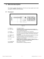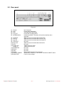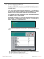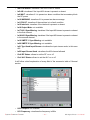
1
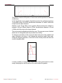
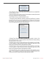
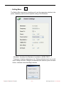
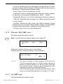
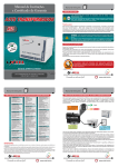
BLUE DIGITAL VIDEO 8VSB version (mod. DTVC) User Manual Volume 1 Superior Broadcast Products Manufactured 171 9 4 P r e s t o n R d .by S u i t e 1 0 2 - 2 9 7 , D a l Italy l a s , T X 7 5 2 4 8 . w w w. s b p - t v. c o m S up e r i o r B ro a d c a s t P roducts where the B est Cost L ess C a l l u s t o d ay. We want to talk to You Superior Broadcast Products Jimmie Joynt 972-473-2577 | 800 279-3326 Benny Springer 214-642-2920 | 800 695-7919 1 7 1 9 4 P r e s t o n R d . S u i t e 1 0 2 - 2 9 7 , D a l l a s , T X 7 5 2 4 8 . w w w. s b p - t v. c o m Superior Broadcast Products B lue D igital Exciter User Manual File Name: BLUE DIGITAL VIDEO_DTVC_8VSB_ING_1.0.indb Version: 1.0 Date: 20/03/2009 Revision History Document History Date Version 20/03/2009 1.0 Reason Editor E. montagna / P. Marras First Edition DTVC - User Manual Version 1.0 © Copyright 2009 R.V.R. Television Superior Broadcast Products R.V.R. Elettronica S.p.A. Via del Fonditore - 40138 - Bologna (Italia) 17194 Preston Rd. Suite 102-297,2/2c Dallas, TX 75428 Telephone: +39 051 6010506 Tel: 800 279-3326 | 800 695-7919 Fax: +39 051 6011104 www.sbp-tv.comEmail: [email protected] Web: www.rvr.it All rights reserved Printed and bound in Italy. No part of this manual may be reproduced, All rights reserved. memorized or transmitted in any form or by any means, electronic or mechanic, including photocopying, recording or by any information storage and retrieval system, without written permission of the copyright owner.. No part of this manual may be reproduced, memorized or transmitted Printed and bound in the U.S.A in any form or by any means, electronic or mechanic, including photocopying, recording or by any information storage and retrieval system, without written permission of the copyright owner. Superior Broadcast Products 1 B lue D igital Exciter User Manual Superior Broadcast Products 2 B lue D igital Exciter User Manual Table of Contents 1. Preliminary Instructions....................................................... 5 2. Warranty................................................................................. 5 3. First Aid.................................................................................. 6 3.1 Treatment of electrical shocks ............................................... 6 3.2 Treatment of electrical Burns ................................................. 6 4. Unpacking . ........................................................................... 7 4.1 General Description ............................................................... 8 5. Quick guide for installation and use .................................. 9 5.1 Preparation ............................................................................ 9 5.2 First power-on and setup ...................................................... 10 6. Operating System ............................................................... 12 6.1 Using the encoder ................................................................. 12 6.2 Software ............................................................................... 13 7. Technical Specifications .................................................... 38 8. Working Principles/Functional Description ........................ 39 8.1 RF Confi gurations . ............................................................. 39 8.2 Power Supply ........................................................................ 39 8.3 Cooling system ..................................................................... 39 8.4 CPU (MAIN BOARD)............................................................ 39 8.5 Modulator ............................................................................ 40 8.6 PA Interface Card .................................................................. 40 9. External description ........................................................... 41 9.1 Front panel ............................................................................ 41 9.2 Rear panel ............................................................................ 42 9.3 Connectors .......................................................................... 43 10. Systems Status Enquires.................................................... 44 11. Abbreviations ...................................................................... 47 Superior Broadcast Products 3 B lue D igital Exciter User Manual DTVC Superior Broadcast Products 4 B lue D igital This page was intentionally leftExciter blankUser Manual DTVC IMPORTANT The lightning ash with arrowhead, within a triangle, is intended to alert the user of the presence of dangerous voltage that may constitute a risk of electric shock. The exclamation point within an equilateral triangle is intended to alert the user to the presence of important operating and maintenance (servicing) instructions in the literature accompanying the equipment. 1. Preliminary Instructions Operation of this equipment in a residential area may cause radio interference, in which case the user may be required to take adequate measures. • General Warnings The specications and data contained herein are provided for information only and are subject to changes without prior notice. R.V.R. Television disclaims all warranties, express or implied.While R.V.R. Television attempts to provide accurate information, it cannot accept responsibility or liability for any errors or inaccuracies in this manual, including the products and the software described herein. R.V.R. Television reserves the right to make changes to equipment design and/or specications and to this manual at any time without prior notice. This equipment should only be operated, installed and maintained by “trained” or “qualied” personnel who are familiar with risks involved in working on electric and electronic circuits. “Trained” means personnel who have technical knowledge of equipment operation and who are responsible for their own safety and that of other unqualied personnel placed under their supervision when working on the equipment. “Qualified” means personnel who are trained in and experienced with equipment operation and who are responsible for their own safety and that of other unqualied personnel placed under their supervision when working on the equipment. • Notice concerning product intended purpose and use limitations. This product is a radio transmitter suitable for frequencymodulation audio radio broadcasting. Its operating frequencies are not harmonised in designated user countries. Before operating this equipment, user must obtain a licence to use radio spectrum from the competent authority in the designated user country. Operating frequency, transmitter power and other characteristics of the transmission system are subject to restrictions as specied in the licence. WARNING: Residual voltage may be present inside the equipment even when the ON/OFF switch is set to Off. Before servicing the equipment, disconnect the power cord or switch off the main power panel and make sure the safety earth connection is connected. Some service situations may require inspecting the equipment with live circuits. Only trained and qualied personnel may work on the equipment live and shall be assisted by a trained person who shall keep ready to disconnect power supply at need. 2. La R.V.R. Television warrants this product to be free from defects in workmanship and its proper operation subject to the limitations set forth in the supplied Terms and Conditions. Please read the Terms and Conditions carefully, as purchase of the product or acceptance of the order acknowledgement imply acceptance of the Terms and Conditions. For the latest updated terms and conditions, please visit our web site at WWW.RVR.IT. The web site may be modied, removed or updated for any reason whatsoever without prior notice. The warranty will become null and void in the event the product enclosure is opened, the product is physically damaged, is repaired by unauthorised persons or is used for purposes other than its intended use, as well as in the event of improper use, unauthorised changes or neglect. In the event a defect is found, follow this procedure: R.V.R. Television shall not be liable for injury to persons or damage to property resulting from improper use or operation by trained/untrained and qualied/unqualied persons. WARNING: The equipment is not water resistant. Any water entering the enclosure might impair proper operation. To prevent the risk of electrical shock or re, do not expose this equipment to rain, dripping or moisture. Please observe local codes and re prevention rules when installing and operating this equipment. 1 WARNING: This equipment contains exposed live parts involving an electrical shock hazard. Always disconnect power supply before removing any covers or other parts of the equipment. Contact the seller or distributor who sold the equipment; provide a description of the problem or malfunction for the event a quick x is available. Sellers and Distributors can provide the necessary information to troubleshoot the most frequently encountered problems. Normally, Sellers and Distributors can offer a faster repair service than the Manufacturer would. Please note that Sellers can pinpoint problems due to wrong installation. Ventilation slits and holes are provided to ensure reliable operation and prevent overheating; do not obstruct or cover these slits. Do not obstruct the ventilation slits under any circumstances. The product must not be incorporated in a rack unless adequate ventilation is provided or the manufacturer’s instructions are followed closely. WA R N I N G : T h i s e q u i p m e n t c a n r a d i a t e radiofrequency energy and, if not installed in compliance with manual instructions and applicable regulations, may cause interference with radio communications. WARNING: This equipment is tted with earth connections both in the power cord and for the chassis. Make sure both are properly connected. UserBroadcast ManualProducts Superior Warranty 2 If your Seller cannot help you, contact R.V.R. Television and describe the problem; if our staff deems it appropriate, you will receive an authorisation to return the equipment along with suitable instructions; 3 When you have received the authorisation, you may return the unit. Pack the unit carefully before shipment; use the original packaging whenever possible and seal the package perfectly. The customer bears all risks of loss (i.e., R.V.R. shall not be liable for loss or damage) until the package reaches the R.V.R. factory. For this reason, we recommend insuring the goods for their full value. Returns must be sent on a C.I.F. basis (PREPAID) to the address stated on the authorisation as specied by the R.V.R. Service Manager. Rev. 1.0 5 - 20/11/09 1 / 44User Manual B lue D igital Exciter DTVC 4 Units returned without a return authorisation may be rejected and sent back to the sender. • Do not stop chest compressions while giving articial breathing. Be sure to include a detailed report mentioning all problems you have found and copy of your original invoice (to show when the warranty period began) with the shipment. • Call for medical help as soon as possible. 3.1.2 Please send spare and warranty replacement parts orders to the address provided below. Make sure to specify equipment model and serial number, as well as part description and quantity. R.V.R. Television Via del Fonditore, 2/2c 40138 BOLOGNA ITALY Tel. +39 051 6010506 3. First Aid 3.1.1 the neck and tilt the head backwards to free • Loosen the victim’s clothing and have him/her lie down. • Call for medical help as soon as possible. Large burns and broken skin Follow the rst aid procedures outlined below. • Try to reassure the victim. 3.2.1 If the victim is unconscious Lay the victim down on his/her back on a rm surface. Cover victim with a blanket. • Treatment of electric burns Electric shock treatment • • 3.2 All personnel engaged in equipment installation, operation and maintenance must be familiar with rst aid procedures and routines. 3.1 If the victim is conscious • Cover affected area with a clean cloth or linen. • Do not break any blisters that have formed; remove any clothing or fabric that is stuck to the skin; apply adequate ointment. • Administer adequate treatment for the type of accident. • Get the victim to a hospital as quickly as possible. • Elevate arms and legs if injured. If medical help is not available within an hour, the victim is conscious and is not retching, administer a solution of table salt and baking soda (one teaspoon of table salt to half teaspoon of baking soda every 250 ml of water). the airway system (Figure 1). Have the victim slowly drink half a glass of solution for four times during a period of 15 minutes. Stop at the rst sign of retching. Do not administer alcoholic beverages. 3.2.2 Figure 1 • If needed, open the victim’s mouth and check for breathing. • If there is no breathing, start articial respiration without delay (Figure 2) as follows: tilt the head backwards, pinch the nostrils, seal your mouth around the victim’s mouth and give four fast rescue breaths. Minor burns • Apply cold (not ice cold) strips of gauze or dress wound with clean cloth. • Do not break any blisters that have formed; remove any clothing or fabric that is stuck to the skin; apply adequate ointment. • If needed, have the victim change into clean, dry clothing. • Administer adequate treatment for the type of accident. • Get the victim to a hospital as quickly as possible. • Elevate arms and legs if injured. Figure 2 • Check for heartbeat (Figure 3); if there is no heartbeat, begin chest compressions immediately (Figure 4) placing your hands in the centre of the victim’s chest (Figure 5). Figure 3 Figure 4 Figure 5 • One rescuer: give 2 quick rescue breaths after each 15 compressions. • Two rescuers: one rescue breath after each 5 compressions. 2 / 44 Superior Broadcast Products Rev. 1.0 - 20/11/09 6 User Manual B lue D igital Exciter User Manual DTVC 4. Unpacking The package contains: 1 DTVC (alias BLUE DIGITAL VIDEO) 1 User Manual 1 Mains power cable The following accessories are also available from Your R.V.R. Dealer: • 4.1. 4.1.1 Accessories, spare parts and cables General Description Introduction The DTVC modulator is congured as 8VSB. To order please specify the model type. All versions are equipped with linear and not linear precorrector. The DTVC is a modulator, there is no need to calibrate lters or other parts in order to change channel. 4.1.2 4.1.3 Main features • 8VSB, FULL COMPLIANT • VHF - UHF DIRECT BAND • ASI1 AND ASI2 DIGITAL INPUT • SMPTE-310M/TS DIGITAL INPUT • LINEAR EQUALIZER WITH JAVA INTERFACE • NON LINEAR PRECORRECTION WITH JAVA INTERFACE • S/N (MER) 32 dB MINIMUM • RF SOFT START • RVR STANDARD TELEMETRY • JAVA TELEMETRY VIA USB • 19”, 2 UNIT RACK • FULL-RANGE POWER SUPPLY 90-250VAC Components • Main Power supply • Main Digital modulator • Display LCD • Bus • RF pre-driver Superior UserBroadcast ManualProducts 7 - 20/11/09 Rev. 1.0 B lue D igital Exciter 3 / 44User Manual DTVC 4.1.4 • ASI interface • Telemetry and telecontrol interface • Power control and protection • Directional coupler • RF driver • RF amplier Front and rear panel The front panel contains the following indications and connectors: • BNC connector for RF MONITOR • Optical encoder • LCD display (2x40 character) • Status indicator LED • USB ready • Blowers The rear panel contains the following connectors 4 / 44 • AC mains input & ON/OFF switch • SMA for digital stream input: ASI1, ASI2 • SMA reference input for 10MHz • SMA reference output (monitor) for 10MHz • DB9 for RS232 (service) • BNC for interlock • N for RF OUTPUT • Ground reference • DB9 for RS485/I2C (SERVICE) Superior Broadcast Products Rev. 1.0 - 20/11/09 8 User Manual B lue D igital Exciter User Manual DTVC 5. Quick guide for installation and use This section provides a step-by-step description of the machine installation and conguration procedure. Follow these procedures closely upon rst power-on and each time any change is made to general conguration, such as when a new transmission station is added or the amplier is replaced. Once the desired conguration has been set up, no more settings are required for normal operation; at each power-up (even after an accidental shutdown), the amplifier defaults to the parameters set during the initial configuration procedure. The topics covered in this section are discussed at greater length in the next sections, with detailed descriptions of all hardware and rmware features and capabilities. Please see the relevant sections for additional details. 5.1 5.1.1 Preparation Preliminary checks Unpack the amplier and immediately inspect it for transport damage. Ensure that all connectors are in perfect condition. Provide for the following (applicable to operating tests and putting into service): √ Full-range 90 to 250 VAC through internal connector, mains power supply with adequate ground connection √ For operating tests only: dummy load with 50 Ohm impedance and adequate capacity √ Connection cable kit including: • 5.1.2 Mains power cable Connections The main fuse can be accessed from the outside, on the rear panel. Extract the fuse holder using a screwdriver and make sure that it is intact; replace it if necessary. Connect a suitable dummy load with suitable dissipation power, or antenna, or the input of nal amplier to the RF output (see gure 9.2 - item [2]) using a 50-Ohm coaxial cable with “N”-type connectors. Note: When you connect the DTVC to other devices, it is necessary to strictly follow the instructions given by the respective manufacturers, to avoid damages or danger situations. Superior Broadcast Products 9 B lue D igital Exciter User Manual DTVC WARNING: Electric shock hazard. Never handle the RF output connector when the machine is powered on and no load is connected. Injury or death may result. Ensure that the POWER switch on the rear panel is set to “OFF”. Connect the mains power cable to the MAINS terminal board on the rear panel. Note : The mains must be equipped with adequate ground connection properly connected to the machine. This is a pre-requisite for ensuring operator safety and correct operation. Connect the cable with an ASI signal to the relevant connector (ASI1 or ASI2) on the back of the machine using a 75-Ohm coaxial cable with SMA connectors. 5.2 First power-on and setup Follow this procedure upon rst power-on and after making changes to the conguration of the transmitter in which the amplier is integrated. Note : Standard factory settings are RF power output Off (Pwr OFF) and output power set to 0 (unless otherwise specied by customer). 5.2.1 Power-on Question: The equipment is turn off? Answer: • When you have performed all of the connections described in the previous paragraph, power on the amplier using the suitable power switch on the rear panel. Start up informations should appear briey on the display, quickly followed by the main readings. If RF output is disabled, these readings will be zero. 5.2.2 Frequency lock check Question: The equipment doesn’t work correctly? Answer: • Wait at least 15 seconds from the power on of DTVC, after which the PLL is locked to working frequency. In case of PLL is not locked, LED ALARMS light turns on and the problem is stored in ALARMS menu. Superior Broadcast Products 10 B lue D igital Exciter User Manual DTVC 5.2.3 Power check Question: The equipment doesn’t work correctly at the power set up? Answer: • Ensure that the INTERLOCK light turns off. It indicates that no external interlock signal inhibites the delivering power from exciter. • Ensure that the ASI Input is performed by 75 Ohm cables with SMA connectors. • Check current RF output setting and enable output (if not already enabled) following menu path SET ⇒ Power ⇒ ( xxx ). Output power can also be set in a Pwr OFF condition; in this condition, (Fwd) output power reading on the display will be 0 (zero), that will be delivered the moment you switch back to Pwr ON state. • Check output power level and set to the desired level from the Power Menu, which you can call up by pressing these keys in the order: SET ⇒ Power ⇒ Power: xxx %. Set the desired amplier output power, whereas the forward power value shown on the display (Power: xxx %) gives actual output power reading. Superior Broadcast Products 11 B lue D igital Exciter User Manual DTVC 6. Operating System The exciter is controlled by a microprocessor system. Software operations may be grouped into two broad categories: start-up and normal operation. 6.1 Using the encoder The interaction between the user and the exciter’s control software is performed using the encoder. Turn the encoder counterclockwise to move the cursor downwards, to decrease the value of a parameter or to choose an element from a list of possibilities Turn the encoder clockwise to move the cursor upwards, to increase the value of a parameter or to choose an element from a list of possibilities Push the button once to enter in the desired menu, to enter in modication mode or to conrm a choice Figure 6.1 The possible operations that you can carry out on the encoder are: • rotation: moves the cursor shown on the display; if you turn the encoder to the left (counterclockwise), the cursor moves downwards, if you turn it right the cursor moves upwards; it also permits to increase or diminish the parameters (turning the encoder left diminishes the parameter, turning it right increases it) or to select an item from a list of options. • pushing: push the button once when the cursor is on the name of a menu to enter in that menu, push it when the cursor is on the name of a parameter to enter in modication mode (the cursor starts blinking); after the modication of a parameter, push the button to keep x the new value. Set the value by pressing the button, to save in memory you need to press OK that causes also the exit from menu. Press ESC if you do not want saving it, that causes the exit keeping the value unchanged; instead in Power Menu (set => power) simply conrm the selection and the value will be saved. If no controls are operated during 2 minutes, the exciter returns to the default menu. Superior Broadcast Products 12 B lue D igital Exciter User Manual DTVC 6.2 6.2.1 Software Start-up Upon switch-on, a window that holds and machine informations appears on the display. The informations regards the date and hour. Superior Broadcast 24/03/2009 8VSB MODULATOR 10:28:39 Figure 6.1- Example of start-up screen 6.2.1.1 Preset through encoder at Start-up After the start-up operation the following window is visualized: :: :: ATTENTION! PRESS BUTTON to Pre-Set :: :: 07 Figure 6.2 Holding press the encoder button during switch-on, the power goes to zero and an alternative main window appears on the display. :: :: ATTENTION! Setting … :: :: Figure 6.3 Password: **** Ï Esc Ok Figure 6.4 Insert password, when requested, to access to the preset menu, then press OK to conrm; select ESC to return to normal start-up menu. Note: in case of rst start-up you can select OK directly to access to preset menu, otherwise insert the password stored prevously. Frequency Ï Power Precorrection Figure 6.5 Superior UserBroadcast ManualProducts 13 - 20/11/09 Rev. 1.0 B lue D igital 9 Exciter / 44User Manual DTVC The setting about paramaters on preset menu is the same of the SET menu decribed in the following. 6.2.2 Default menu This is an information screen; it shows the main measures. To access to the Selection submenus press the encoder, turn until the indicator is highlighted on the desired menu and then press again to conrm. If no controls are operated through the encoder during 2 minutes, the exciter returns to this menu and after 5 minutes of inactivity the display lighting will be turning off. CH:485,000Hz Alarms FWD: 10.0W ÎStatus RFL:0.00W Set Figure 6.6 CH FWD RFL 6.2.3 Visualization of the frequency in transmission (CHannel) Visualization of the forward power Visualization of the reected power Alarms Under this menu is possible enter inside two submenus about alarms status on the equipment. Turning he encoder, you can move the cursor to between Reset Alarm and Alarm List submenus. Status Under this menu is possible view the measures and the main settings about the equipment, scrolling through multiple pages by rotating the encoder. To exit press the encoder. Set Under this menu is possible enter inside to several submenu about the setting of equipment. Turning the encoder, you can move the cursor to the next submenu label, the name is displayed in the upper part of the screen. Reset Alarms (ALARMS menu) This menu provides the restore of all the memorized alarms in the DTVC. Reset Alarms Ï Alarms List(00) Figure 6.7 Superior Broadcast Products 14 B lue D igital Exciter User Manual DTVC 6.2.4 Alarms List (ALARMS menu) This menu visualize the historic alarms, the number of alarms memorized is indicated in parentheses. Reset Alarms Alarms List(00) Ï Figure 6.8 At each alarm is associate the date when it happened. The possible alarms are as follows: Input stream absent Alarm ID1 - Input non present or synchronization loss FWD Protection Alarm ID2 - Hardware blockage on output power RFL Protection Alarm ID3 - Hardware blockage on output power Over Temperature Alarm ID4 - Over-temperature protection ALC out Range Alarm ID5 - Automatic Level Control out-of-range PLL Unlocked Alarm ID6 - PLL not locked PA Out Control Alarm ID7 - Absence of communication with PA RS absent Driver PA Absent Alarm ID8 - The signal is not present in the internal amplication card Out of Service (F3) Alarm ID9 - The equipment is in Out-of-Service status caused by FPGA. NO RF DRIVER CARD Alarm ID10 - The internal amplication card is not present in the driver slot NO ASI CARD Alarm ID11 - The ASI internal card is not present in the driver slot Out of Service (PWD) Alarm ID12 - The equipment is in Out-of-Service status caused by generic alarm. Superior Broadcast Products User Manual 15 Rev. 1.0 - 20/11/09 B lue D igital Exciter User Manual 11 / 44 DTVC 6.2.4.1 Alert Management The alert management presents two conditions encompasses in same behaviour, in other words it manages two states of the equipment. ALARM First Condition: The rst condition temporarily inhibit the output power of transmitter and are signalled through the ALARM led turns on. Alarm counter increases by 1 unit, machine goes into lock-out state and the display shows the cause for the stop. After the times described below, the machine attempts to re-start; if a new alarm condition is detected, cycle is repeated over and over again up to 10 times maximum. If machine re-starts successfully, all alarm counters are reset after some minutes of regular operation (the alarms are displayed in the ALARM LIST menu, with date and time of occurrence). After 10 alarm conditions triggered by the same cause, the machine goes into fault lock-out mode, a lock-out mode warning appears on the display and the FAULT led turns on. The alarm is generated in these cases: • Digital Input Stream Absence. Waits 3 Seconds. After 10 attempts, it not generates FAULT condition. • Overtemperature protection. Waits 3 Seconds. After 10 attempts, it not generates FAULT condition. • Hardware protection of internal forward power. Waits 10 Minutes. After 10 attempts, it generates FAULT condition. • Hardware protection of internal reected power. Waits 10 Minutes. After 10 attempts, it generates FAULT condition. • Absence of ASI driver or PA driver. Waits 3 Seconds. After 10 attempts, it not generates FAULT condition. ALARM Second Condition: The second condition not inhibit the output power of transmitter and are signalled through the ALARM led turns on. The alarm is generated in these cases: • Software protection of modulator out of control. • Software protection of modulator with HW/SW internal problems. • Software protection of ALC out of limits alert. FAULT Condition: This condition is generated after 10 ALARM conditions triggered by the same cause, the machine goes into fault lock-out mode, and is signalled through the FAULT led turns on, through Graphic User Interface. 12 / 44 Superior Broadcast Products Rev. 1.0 - 20/11/09 16 User Manual B lue D igital Exciter User Manual DTVC 6.2.5 Frequency (STATUS menu) This menu visualize the information regards the readings of working parameters. Rotating the encoder clockwise to pass to next readings. - 8VSB Modulator Frequency: 773,000,000Hz Ð Figure 6.9 Standard Visualization of the 8VSB standard and current date. Frequency Visualization of working frequency 6.2.6 Power and System (STATUS menu) This menu visualize the information regards the readings of working parameters. Rotating the encoder clockwise to pass to next readings, otherwise rotating it counter-clockwise to pass to previous readings. FWD: 0.0W PRE: Table1 RFL: 0.00W EQU: On Figure 6.10 FWD RFL PRE EQU 6.2.7 Visualization of the Forward Power. Visualization of the Reected Power. Visualization of the current selected precorrection table. Visualization of the equalization status. Current and Voltage (STATUS menu) This menu visualize the information regards the readings of working parameters. Rotating the encoder clockwise to pass to next readings, otherwise rotating it counter-clockwise to pass to previous readings. Ï VPA : 33.9V IDRV: 1.34A IPA: 1.59A Ð Figure 6.11 VPA User Manual Superior Broadcast Products Visualization of the amplier module voltage. Rev. 1.0 - 20/11/09 17 13 / 44 B lue D igital Exciter User Manual DTVC IPA IDRV 6.2.8 Visualization of the amplier module current. Visualization of the driver current. Temperature (STATUS menu) This menu visualize the information regards the readings of working parameters. Rotating the encoder clockwise to pass to next readings, otherwise rotating it counter-clockwise to pass to previous readings. Ï Temp .FPGA 1: 25° Temp.Total: 25° Temp.FPGA2: 25° Temp .PA: 38° Ð Figure 6.12 Temp FPGA1 Visualization of the temperature on FPGA1. Temp FPGA2 Visualization of the temperature on FPGA2. Temp Total Visualization of the internal temperature. Temp PA 6.2.9 Visualization of the temperature on power amplier module. Reference (STATUS menu) This menu visualize the information regards the readings of working parameters. Rotating the encoder clockwise to pass to next readings, otherwise rotating it counter-clockwise to pass to previous readings. Ï Ref. 10MHz: Internal Auto Ð Figure 6.13 Ref 10MHz Visualization of the 10MHz status (Internal or Extermal and Auto or Manual). 6.2.10 Input (STATUS menu) This menu visualize the information regards the readings of working parameters. Rotating the encoder clockwise to pass to next readings, otherwise rotating it counter-clockwise to pass to previous readings. Superior Broadcast Products 14 / 44 18 Rev. 1.0 - 20/11/09 B lue D igital Exciter User Manual User Manual DTVC Ï Input: Presence A Ð Figure 6.14 Input 6.2.11 Visualization of presence or absence for A or B ASI stream Frequency (SET menu) This menu provides the setting on exciter. Note: to access in this menu please read the note in chap 6.2.2 Frequency Ï Power Precorrettion Figure 6.15 Rotating the encoder clockwise to pass to next settings. Press the encoder to access the editing of single parameters. Frequency: 485,000,000Hz Ï Esc Ok Figure 6.16 Frequency Selection of the channel frequency. The frequency channel set emulates the traditional rotary switches. By placing the cursor in each of the nine digits you can change the value from 0 to 9, so the frequency channel had a precision of 1 Hz. Selecting OK this setting is stored, otherwise selecting ESC each variation is ignored and you return in the previous menu. 6.2.12 Connection and Firmware Version (STATUS menu) This menu visualize the information regards the rmware and the connection status of equipment. Frequency: 485,000,000Hz Ï Esc Ok Figure 6.17 Connection Visualization of the local or remote status. Ver. Rel. 6.2.13 Visualization of the rmware version. Visualization of the rmware release. Power (SET menu) User Manual Superior Broadcast Products Rev. 1.0 - 20/11/09 19 15 / 44 B lue D igital Exciter User Manual DTVC This menu provides the setting on exciter. Note: to access in this menu please read the note in chap 6.2.2 Frequency Power Ï Precorrection Figure 6.18 Rotating the encoder clockwise to pass to next settings. Press the encoder to access the editing of single parameters. In the current menu is displayed the power measured as percentage and in W. ( On ) Power Ï : 50% 9.9W Esc Ok Figure 6.19 ( ON ) POWER Enables (On) or disables (Off) the power supply of the exciter. Selection of the output power percentage desired. In case which the percentage is set at 0%, the power turns off (output power disabled) and the RF led lit off. When the percentage is set at another value, the power turns on, the RF led lit on and the ramp starts for leading the selected value. Note: pushing the encoder button after the selection the value is conrmed, it will be save directly on ash memory (do not need to select OK from the same menu). 6.2.14 Precorrection (SET menu) This menu provides the setting on exciter. Note: to access in this menu please read the note in chap 6.2.2 Frequency Power Precorrection Ï Figure 6.20 Rotating the encoder clockwise to pass to next settings. Press the encoder to access the editing of single parameters. In the current menu you can choose between No-Linear and Linear: Superior Broadcast Products 16 / 44 20 Rev. 1.0 - 20/11/09 B lue D igital Exciter User Manual User Manual DTVC No-Linear Ï Linear Figure 6.21 Selecting no-linear precorrection you can modify the following parameter: Select Table : Î Default Esc Ok Figure 6.22 Select Table This menu provides to select between thirty non-linear pre-distortion tables previously set in a java graphical ambient and downloaded to the machine via USB port. The linear pre-correction of group delay is unique and it is also previously set in a java graphical ambient. The selection can be automated in relation to the power output, if required. Only one linear and six non-linear table will be available initially. Selecting linear precorrection you can modify the following parameter: Equalization : Î On Esc Ok Figure 6.23 Equalization This menu provides to select between ON or OFF. 6.2.14.1 Pre-correction guide on JAVA graphical ambient The Java Virtual Interface has been created to permit the user, in a simple and intuitive way, to monitor the measures and the status of the Modulator device, to control all internal settings and to load and save precorrection’s and equalization’s curves. With few clicks is possible to change, modify and make operative linear and nolinear precorrection’s curves, through an intuitive graphical interface, different tables, and optimization’s procedures. - Installation 1. Make sure that an opportune version of Java Runtime Environment© is installed in your computer. Assure that it is not less than 1.6.0 ( if you do not know the actual JRE installed, simply write java – version in the prompt of your system). In every case an 1.6.0 version is included in the Installation Cd provided with the Modulator. Superior Broadcast Products User Manual 21 Rev. 1.0 - 20/11/09 B lue D igital Exciter User Manual 17 / 44 DTVC 2. Turn on the Modulator and plug in the Usb cable between the computer and the device. When the Virtual COM’s driver is requested you can nd it in the Cd provided with the device and install it. 3. Unplug the Usb cable from the computer 4. Load the Cd on your computer, it will start automatically ( otherwise open the Installation Cd and run BDVInstaller.exe ). Follow the installation instruction until the end. 5. The Java Virtual Interface is correctly installed. - General The rst screen looks like this: The meaning of every single items will be explained in different following section of this chapter. The tool bar is shown in the following gure: Follows an explanation of every single button: [1] Access to the previous menu [2] Access to the next menu [3] Save the setting’s value in a le 18 / 44 Superior Broadcast Products Rev. 1.0 - 20/11/09 22 User Manual B lue D igital Exciter User Manual DTVC [4] Print the setting’s value [5] Access to the Status Menu [6] Access to the Precorrection Menu [7] Access to the Equalization Menu [8] Access to the Setting Menu [9] Search value [10] Exit saving or without save Clicking this button it will appear a dialog window: When the Usb cable is plugged in, Java Virtual Interface will recognize the Virtual Port automatically and show it in the following section: - Status Menu The Status Menu provides to allow the visualization of the general parameters and standard measures relative to the power, frequency, temperatures and alarms of the Modulator. The page is divided in four sections: General, Temperature, Measure and Alarm. User Manual Superior Broadcast Products Rev. 1.0 - 20/11/09 23 19 / 44 B lue D igital Exciter User Manual DTVC • General ◦ Menu type: Visualizes the Standard of modulation ( 8VSB, DVB-T, ...) ◦ Mode: Visualizes if the device is set Local or Remote ◦ ALC: Visualizes if the Automatic Level Control is Present or Absent ◦ Frequency: Visualizes frequency in Hz ◦ Power: Visualizes the power’s percentage set ◦ PLL: Visualizes if the PLL is Locked or Unlocked ◦ Stream ASI: Visualizes if the ASI Stream is Present or Absent • Temperature ◦ PA Temperature: Visualizes the measure of the Power Amplifier’s temperature ◦ Local Temperature: Visualizes the measure of the Main Board’s temperature ◦ FPGA1 Temperature: Visualizes the measure of the FPGA1’s temperature ◦ FPGA2 Temperature: Visualizes the measure of the FPGA2’s temperature Superior Broadcast Products 24 B lue D igital Exciter User Manual DTVC • Measure ◦ Direct Power: Visualizes the measure of the Direct Power ◦ Reex Power: Visualizes the measure of the Reected Power ◦ PA Voltage: Visualizes the measure of the Power Amplier’s voltage ◦ PA Current: Visualizes the measure of the Power Amplier’s current ◦ IDRV Current: Visualizes the measure of the Power Driver’s current • Alarm Visualizes the alarm list and the time of occurrence: ◦ ALARM1 → Input stream absent : Input non present or synchronization loss ◦ ALARM2 → FWD Protection : Hardware blockage on output power ◦ ALARM3 → RFL Protection : Hardware blockage on output power ◦ ALARM4 → Over Temperature : Over-temperature protection ◦ ALARM5 → ALC out Range : Automatic Level Control out-of-range ◦ ALARM6 → PLL Unlocked : PLL not locked ◦ ALARM7 → PA Out Control : Absence of communication with PA RS absent ◦ ALARM9 → Driver PA Absent : The signal in the internal amplication card is not present ◦ ALARM10 → Out of Service (F3) : The equipment is in Out-of-Service status caused by FPGA3. ◦ ALARM11 → NO RF DRIVER CARD : The internal amplication card is not present in the driver slot ◦ ALARM12 → NO ASI CARD : The ASI internal card is not present in the driver slot ◦ ALARM13 → Out of Service (PWD) : The equipment is in Out-of-Service status caused by generic alarm. Superior Broadcast Products 25 B lue D igital Exciter User Manual DTVC - Precorrection Menu The Precorrection Menu allows to modify, load and save the No-linear Precorrection curves. • Select Amplitude or Phase Permits to choose what type of graphic change. • Load Curve from Modulator Permits to load all the curves memorized (both Precorrection’s and Equalization’s) in the modulator. When the curves are correctly loaded, it will be wrote “Loaded”. • Amplitude’s and Phase’s Graphic Superior Products 22 / Broadcast 44 Rev. 1.0 - 20/11/0926 B lueUser D igitalManual Exciter User Manual DTVC The graphics consist of 64 points, to have more and ne precision in denition of the curve. In the “AM-AM curve” graphic (Amplitude section) the ordinate is between -6 and 6dB in steps of 0.01dB, the abscissa is between -12 and 12 dB with 64 points at the same distance. Similarly in the “AM-PM curve” graphic (Phase section) the ordinate is between -25 and 25° in steps of 0.01°, the abscissa is between -12 and 12 with 64 points at the same distance. The red curves are dened and edited from user. The gray are curves of default which are not changeable and are provided from factory. To change a parameter of the curve just select one point of the graphic and drag it wherever you desire, it will change the respective table’s value and, during the dragging operation, a text close to the mouse pointer will show the current changing value. It is also possible to change every single value of the precorrection’s curves simply changing the value inside the four tables under the graphic. Superior Broadcast Products 27 B lue D igital Exciter User Manual DTVC The rst two tables are referred to the Default values, therefore cannot be modied, and are referred to the amplitude and to the phase. The last two tables are the ones that are currently viewed in the present graphic and can be modied for what concerns amplitude and phase by the user. On the rst column of each table it is pointed out the xed abscissa and on the second column the ordinate which value can be modied by the user. The buttons allow to do the main operations: ◦ Save Tables: allows to save all the precorrection’s curves on different text’s les located in the /TABLE directory. ◦ Load Tables: allows to load all the precorrection’s curves from different text’s les located in the /TABLE directory. ◦ Refresh: allows to send the current curve (both amplitude and phase) to the modulator, making effective in the spectrum the table’s changing. ◦ Table selector: allows to select what type of table is visualized (Table0(Default), Table1, ..., Table6). ◦ Set Operative: allows to set the current curves (both amplitude and phase) as the active curve in the modulator at every start up. Superior Broadcast Products 28 B lue D igital Exciter User Manual DTVC ◦ Precorrection OFF: allows to turn off the precorrection’s function. ◦ Reset Selected: allows to set every value of the selected curve(amplitude’s or phase’s) to zero. ◦ Save in FLASH Current: allows to save in the modulator’s ash memory the selected curve (both amplitude’s and phase’s). ◦ The section Interval Selection permits a simple and useful way to create a curve without the need to move every graphical point. Simply set in the abscissa the Start point, then the Stop point and nally the Internal point and a quadratic curve will be generated among the selected points. ◦ Activate Curve Generator: to select this radio button permits to enter in the Interval Selection mode. It is also possible to select this button directly clicking the central button of the mouse. ◦ Set Start Position: allows to select the rst point of the quadratic curve’s range. It is also possible to select this button directly clicking the right button of the mouse until the desired button’s label becomes reddish. ◦ Set Stop Position: allows to select the last point of the quadratic curve’s range. It is also possible to select this button directly clicking the right button of the mouse until the desired button’s label becomes reddish. ◦ Set Internal Position: allows to select the mean point of the quadratic curve’s range. It is also possible to select this button directly clicking the right button of the mouse until the desired button’s label becomes reddish. - Equalization Menu The Equalization Menu allows to modify, load and save the Linear Precorrection’s curves. Superior Broadcast Products 29 B lue D igital Exciter User Manual DTVC • Select Amplitude or Group Delay Permits to choose what type of graphic change. • Load Curve from Modulator Permits to load all the curves memorized (both Precorrection’s and Equalization’s) in the modulator. When the curves are correctly loaded, it will be wrote “Loaded”. • Amplitude’s and Group Delay’s Graphic Superior Broadcast Products 30 B lue D igital Exciter User Manual DTVC The graphics consist of 64 points, to have more and ne precision in denition of the curve. In the “Amplitude curve” graphic (Amplitude section) the ordinate is between -3 and 3dB in steps of 0.01dB, the abscissa is between -4.2 and 4.2 MHz with 64 points at the same distance. Similarly in the “Group Delay curve” graphic (Phase section) the ordinate is between -100 and 100ns in steps of 0.01ns, the abscissa is between -4.2 and 4.2 MHz with 64 points at the same distance. The red curves are dened and edited from user. The gray are curves of default which are not changeable and are provided from factory. To change a parameter of the curve just select one point of the graphic and drag it wherever you desire, it will change the respective table’s value and, during the dragging operation, a text close to the mouse pointer will show the current changing value. It is also possible to change every single value of the precorrection’s curves simply changing the value inside the four tables under the graphic. Superior Broadcast Products 31 B lue D igital Exciter User Manual DTVC The rst two tables are referred to the Default values, therefore cannot be modied, and are referred to the amplitude and to the group delay. The last two tables are the ones that are currently viewed and can be modied for what concerns amplitude and group delay by the user. On the rst column of each table it is pointed out the xed abscissa and on the second column the ordinate which value can be modied by the user. The buttons allow to do the main operations: ◦ Save Tables: allows to save all the precorrection’s curves on different text’s les located in the directory /TABLE . ◦ Load Tables: allows to load all the precorrection’s curves from different text les located in the TABLE directory. ◦ Refresh: allows to send the current curve (both precorrection’s and equalization’s) to the modulator, making effective the table’s changing. ◦ Set Operative: allows to set the current curves (both amplitude’s and group delay’s) as the active curve in the modulator. ◦ Equalization OFF: allows to turn off the equalization’s function. Superior Broadcast Products 32 B lue D igital Exciter User Manual DTVC ◦ Reset Selected: allows to set every value of the selected curve (amplitude’s or group delay’s) to zero. ◦ Save in FLASH Current: allows to save in the modulator’s memory the current curve (both amplitude’s and group delay’s). ◦ Send Default: allows to send the default’s curve. ◦ The section Interval Selection permits a simple and useful way to create a curve without the need to move every graphical point. Simply set in the abscissa the Start point, then the Stop point and nally the Internal point and a quadratic curve will be generated among the selected points. ◦ Activate Curve Generator: select this radio button permits to enter in the Interval Selection mode. It is also possible to select this button directly clicking the central button of the mouse. ◦ Set Start Position: allows to select the rst point of the quadratic curve’s range. It is also possible to select this button directly clicking the right button of the mouse until the desired button’s label becomes reddish. ◦ Set Stop Position: allows to select the last point of the quadratic curve’s range. It is also possible to select this button directly clicking the right button of the mouse until the desired button’s label becomes reddish. ◦ Set Internal Position: allow to select the mean point of the quadratic curve’s range. It is also possible to select this button directly clicking the right button of the mouse until the desired button’s label becomes reddish. Superior Broadcast Products 33 B lue D igital Exciter User Manual DTVC - Setting Menu The Setting Menu provides to visualize and to set the parameters relative to the power, frequency, options and the specic setting of the Modulator. ◦ Modulator: Visualizes the Standard of modulation ( 8VSB, DVB-T, ...). ◦ Frequency: Visualizes frequency in Hz. Clicking inside the text’s b ox it will open a dialog’s window. Change to the desired value and then press the Send button, otherwise close the dialog’s window. Superior Broadcast Products 34 B lue D igital Exciter User Manual DTVC ◦ Power(%): Visualize the power’s percentage. Clicking inside the text’s box it will open a dialog’s window. Change to the desired value and then press the Send button, otherwise close the dialog’s window. ◦ Power: Select on or off to set the power on or off. ◦ Precorrection: allows to visualize and to select what type of table is operative on the start up of the modulator (Table0(Default), Table1, ..., Table6). ◦ Equalization: Select on or off to set the equalization’s presence or absence. ◦ 10MHz ref.: Select Automatic or Internal to set 10MHz’s reference automatic or force it internal. ◦ Ref.Offset: Visualizes the offset’s value of the 10MHz’s reference. Clicking inside the text’s box it will open a dialog’s window. Change to the desired value and then press the Send button, otherwise close the dialog window. ◦ ASI Input: Select A or B to set ASI channel A or B. 6.2.15 Reference 10MHz (SET menu) This menu provides the setting on exciter. Note: to access in this menu please read the note in chap 6.2.2 Ref.10MHz Ï Input Option Figure 6.24 Rotating the encoder clockwise to pass to next settings. Press the encoder to access the editing of single parameters. (Auto) Fine Adjust : - 27 ÎEsc Ok Figure 6.25 (AUTO) 6.2.16 This menu provides to select between AUTO and INT. If AUTO is selected in case of a 10 MHz external reference is present, the system switches on it. By the jumper, the internal oven may be forced to stay on and in temperature, then in frequency in the event of a possible switching. If INT is selected, the system is forced to internal reference. In this mode, you can make ne adjustment of ±2.5 ppm in 127 steps. Input (SET menu) This menu provides the setting on exciter. Superior Broadcast Products 35 B lue D igital Exciter User Manual DTVC Note: to access in this menu please read the note in chap 6.2.2 Ref.10MHz Input Ï Option Figure 6.26 Rotating the encoder clockwise to pass to next settings. Press the encoder to access the editing of single parameters. Input Selection : Î A Esc Ok Figure 6.27 Input 6.2.17 This menu provides the ASI primary channel selection. The selection can be automatic or manual between A or B ASI stream. Option (SET menu) This menu provides the setting on exciter. Note: to access in this menu please read the note in chap 6.2.2 Ref.10MHz Input Option Ï Figure 6.28 Rotating the encoder clockwise to pass to next settings. Press the encoder to access the editing of single parameters. LCD Time Menu Pwd Crl ÎEsc Figure 6.29 LCD contrast:: Î Esc Ok Figure 6.30 LCD Superior Broadcast Products This menu provides the adjustment of display contrast. 36 B lue D igital Exciter User Manual DTVC Set Time : 16 : 26 : 55 Ï Esc Ok Figure 6.31 Set Time This menu provides the adjustment of the time. Set Date : 09 / 12 / 2008 Ï Esc Ok Figure 6.32 Set Date This menu provides the adjustment of the date. New Pwd: 123* Ï Esc Ok Figure 6.33 Pwd This menu provides to choose and conrm a password of 4 number. In case you want to change the password, before insert the old password, then choose the new password and conrm. Menu Type : Î Remote Esc Ok Figure 6.34 Menu Type This menu provides to choose between LOCAL (you can control the device only with encoder) or REMOTE (that allows to receive telecontrol from other sorces like Java or I2C bus). Superior Broadcast Products 37 B lue D igital Exciter User Manual DTVC 7. Technical specications General Standards available Frequency range Cooling RF output connector Impedance Load mismatch RF monitor connector Nominal Power 8VSB Reference Shoulder at F0±3MHz Digital modulation Modulation S/N (MER) Mechanical Features Dimensions Weight Operation temperature Storage temperature Max humidity Superior Broadcast Products 8VSB VHF-UHF bandwidth (177-213 / 473-862 MHz 1Hz step ) direct band Forced air N female 50 Ohm 2:1 Max BNC (50 Ohm) 20Wrms (Class A/B) Internal 10MHz 1 ppm for year or external <-36dB(DTV) 8VSB > 32dB for each Power 2 Units, 50©0mm depth 15kg from -10°C to +45°C from -20°C to +85°C 90%, non condensing 38 B lue D igital Exciter User Manual DTVC 8. Working Principles A brief description of each module’s functions is given below, 8.1 RF Congurations The DTVC RF congurations is 20Wrms in class A/B PA. For greater power is possible to connect an external amplier. The power reading is carried out by a directional coupler thru rms with excellent performance in terms of linearity and precision. The driver module is used for regulating the nal output power and in order protect the following ends through timely attenuation of the output power level by 40dB. 8.2 Power Supply The power supply is congured so that it can be easily replaced. There are two power supply modules: one for the modulator section and one for for the PA section. It supports full-range voltages from 90 to 250VAC. It is short-circuit protected. 8.3 Cooling system The machine is equipped with a high performance fan and is included postventilation technology. 8.4 CPU (MAIN BOARD) This card is dened as a microprocessor card that hosts the rmware necessary for the following functions: • User interface (display 2x20 alphanumeric characters, 6 LED panel) • RS232 • RS485 / I2C • Interface card I/O (optoisolated inputs and outputs, analog inputs and outputs) • PA interface • MODULATOR block interface • System Bus interface • Option Management Superior Broadcast Products 39 B lue D igital Exciter User Manual DTVC 8.5 Modulator This appears as a block, made up of three FPGA, connected to the CPU via a dedicated connection. The CPU continuously checks the status of the modulator and the connection. In the case of a fault it signals the event and tries to reset the machine if possible. 8.6 PA Interface Card The interface card performs the following functions: 8.6.1 • Quick measurements and protections on direct and reected power. • Regulation of output power. • Measuring currents at the PA Quick measurements and protections on FWD and RFL power The protection functions intervene in the case of high reected and/or direct power. They act on the driver by removing the RF signal. They intervene very quickly since they are implemented through an analogue network. This then noties the CPU of the protection that has intervened signalling the event with a message. The measurement of the direct and reected power is obtained via the internal/ external directional coupler. These same measurements are also reported on the external telemetry connector. 8.6.2 Regulation of the output power The level of the output power is varied by means of the control signal on the driver. Every time there is a variation in power or a change of channel the machine performs a softstart that sets the output to the dened value. The ALC is inserted to keep the output power constant. This function, controlled via software, is implemented by means of an electronic trimmer. There is no need to perform calibration at each channel change since all compensations have been tabulated in the CPU. Additional hardware protections have also been implemented in case the CPU loses control of the machine status. Superior Broadcast Products 40 B lue D igital Exciter User Manual DTVC 9. External description This chapter includes the elements of the front and rear panels and a short description of DTVC for 8VSB standard. 9.1 Front panel Figure 9.1 [1] DISPLAY [2] LOCAL LED [3] RF LED [4] ALARM LED [5] STREAM LED [6] USB [7] INT.LOCK LED [8] FAULT [9] RF MONITOR [10] ENCODER Superior Broadcast Products LCD graphical display Yellow LED, it is lit on when the exciter is set in Local status. In case the LED ashing, it indicates communications ahead between exciter and TELECON software Green LED, it is lit on when the exciter is switched on Yellow LED, it is lit on in presence of transmitter failure that not stop the working functioning (for example communicaton lack between the modules) Green LED, it is lit on when data streams are present on ASI inputs. For rmware upgrade or Java control and telemetry Red LED, it is lit on when exciter is not delivering power because inhibited by an interlock signal. Red LED, it is lit-on in presence of transmitter failure in case of hardware alarms (for example the breaking of modules). In case the LED ashing, it indicates the temperature alarm. BNC connector for RF test Knob and button for controlling the software 41 B lue D igital Exciter User Manual DTVC 9.2 Rear panel Figure 9.2 [1] [2] [3] [4] [5] Ground ASI1 ASI1 R.F. OUT INTERLOCK IN [6] [7] [8] [9] [10] [11] [12] Output PA DAC IN Input PA 1PPS OUT DAC OUT GPS 10 MHz Out 10 MHz In INTERLOCK RS232 RJ45 RS485 MAINS & POWER MAIN FUSE [13] [14] [15] [16] [17] [18] Superior Broadcast Products 38 / 44 Not Connected Primary ASI1 digital input Secondary ASI1 digital input N connector for output power Interlock input BNC. The exciter is forced into stand-by when grounded. SMA connector, Interconnected with Input PA SMA connector, Interconnected with DAC OUT SMA connector, Interconnected with Output PA Not used SMA connector, Interconnected with DAC IN Not used 10MHz reference output 10MHz reference input Not used Not used Not used DB9 for RVR standard I2C bus telemetry Standard IEC connector for the network. 90-250V & ON/OFF switch Fuse for mains voltage 42 Rev. 1.0 - 20/11/09 B lue D igital Exciter User Manual User Manual DTVC 9.3 9.3.1 Connectors RS232 Type: Female DB9 1 2 3 4 5 6 7 8 9 9.3.2 RS485/I2C Type: Female DB9 1 2 3 4 5 6 7 8 9 9.3.3 NC TX DATA RX_DATA Not connected GND Not Connected Not Connected Not Connected Not Connected Internal Connected (CAN) Internal Connected (CAN) SDA I2C Internal Connected (RS485 B) GND Internal Connected (RS485 A) SCL I2C Internal Connected (RS485 Z) Internal Connected (RS485 Y) RJ45 USB type B 1 2 3 4 Superior Broadcast Products NC DD+ GND 43 B lue D igital Exciter User Manual DTVC 10. System Status Enquiries Through the MOD TLC300 it is possible to manage telecontrol and telemetry with I2C interface via RS485. For a detailed treatment of MOD TLC300 please refer to the specic manual. In this section will be treated the particular measure that it is possible to see in the TELECON user interface, in regards to this specic modulator. For a detailed treatment of TELECON user interface please refer to the specic manual. First of all make sure that the RDMODGSM-TV has a green-face, this indicated that the MOD TLC300 is correctly working. Second make sure that the DTVP-ATSC has a green-face, this indicated that the ATSC modulator is correctly working. Press on the DTVP-ATSC green-face to allow the visualization of the appropriate menu. It will follow a brief explanation of every eld of the measure’s table of I/O section: 40 / 44 • In0 Local/Remote: visualizes if the machine is set in Local or Remote mode • In1 RF: visualizes the RF status (on or off) • In2 ALC: visualizes if the ALC is present or absent Superior Broadcast Products Rev. 1.0 - 20/11/09 44 B lue User D igital Manual Exciter User Manual DTVC • In4 Lock Status: visualizes if the PLL is lock or unlock • In5 ASI: visualizes if the Input ASI stream is present or absent • In9 WAIT: visualizes if it is present an alarm condition that momentary block the RF power • In10 WARNING: visualizes if it is present an alarm message • In11 FAULT: visualizes if the machine is in a fault condition • In12 Interlock: visualizes if the interlock is present or absent • In16 Output Mute: not available • In17 ASI 1 Sync Missing: visualizes if the Input ASI stream is present or absent in the rst channel • In18 ASI 2 Sync Missing: visualizes if the Input ASI stream is present or absent in the second channel • In19 SMPTE 1 Sync Missing: not available • In20 SMPTE 2 Sync Missing: not available • In21 Type Used Input Stream: visualizes the input stream mode, in this case ASI • In22 Input Stream Used: visualizes the ASI channel allowed • Out0 RF Status: allows to set the RF on or off • Out1 ALC Status: allows to set the ALC on or off It will follow a brief explanation of every eld of the measure’s table of General section: • I/O0 Jumpers: not available • I/O1 Frequency: visualizes the frequency in MHz Superior Broadcast Products User Manual 45 Rev. 1.0 - 20/11/09 B lue D igital Exciter User Manual 41 / 44 DTVC • I/O2 Frequency: visualizes the frequency in Khz • I/O3 Frequency: visualizes the frequency in Hz • I/O6 Power Out Level: visualizes and allow to modify the percentage value of Power Out • I/O7 Rise Time: not available • I/O8 Forward Power: visualizes the forward power in W • I/O9 Reected Power: visualizes the reected power in W • I/O12 VPA: visualizes the power amplier voltage • I/O13 IPA: visualizes the power amplier current • I/O14 TEMP: visualizes the power amplier temperature • I/O15 IDRV: visualizes the power driver voltage • I/O16 ALC Status: visualizes the ALC value Superior Broadcast Products 46 B lue D igital Exciter User Manual DTVC 11. Abbreviations 8VSB ALC ASI DHCP DNS DVB DVB-H DVB-SH FEC EXT FFT GPS INT HP IP LP MIP MFN MPE NIT PCR RF RX SHIP SYNC SFN QAM QPSK TI TPS TV TX UHF UTC VHF Superior Broadcast Products 8-level Vestigial Sideband Modulation Automatic Level Control Asynchronous Serial Interface Dynamic Host Conguration Protocol. Domain Name System Digital Video Broadcasting DVB Handheld Systems DVB Satellite to Handheld Systems Forward Error Correction EXTernal Fast Fourier Transform Global Positioning System INTernal High Priority Internet Protocol Low Priority Mega-frame Initialization Packet Multi Frequency Network MultiProtocol Encapsulation Network Information Table Program Clock reference Radio Frequency Receiver SH Initialization Packet SYNChronization Single Frequency Network Quadrature Amplitude Modulation Quaternary Phase Shift Keying Time Interleaving Transmission Parameter Signalling TeleVision Transmitter Ultra-High Frequency Universal Time Clock Very-High Frequency 47 B lue D igital Exciter User Manual This page was intentionally le ft bl ank . Superior Broadcast Products B lue D igital Exciter User Manual S up e r i o r B ro a d c a s t P roducts where the B est Cost L ess C a l l u s t o d ay. We want to talk to You Superior Broadcast Products B lue D igital Exciter User Manual Superior Broadcast Products Jimmie Joynt 972-473-2577 | 800 279-3326 Benny Springer 214-642-2920 | 800 695-7919 1 7 1 9 4 P r e s t o n R d . S u i t e 1 0 2 - 2 9 7 , D a l l a s , T X 7 5 2 4 8 . w w w. s b p - t v. c o m