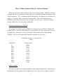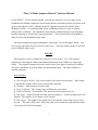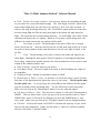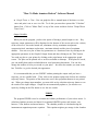
1
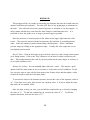
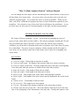
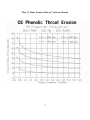
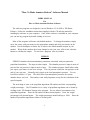
"How To Make Amateur Rockets" Software Manual USERS MANUAL For How to Make Amateur Rockets Software The software programs are designed to run on Windows 95, 98, ME or XP (Home Edition). Follow the installation instructions supplied with the CD and this manual for installing the software on your computer. Once all the software is installed on your computer you can run any program by double clicking on its icon. Most of the programs will come with default numbers. To change the numbers, simply move the cursor with your mouse to the appropriate number and click your mouse on the number. Use the backspace or delete key to remove the default number and put in your number. When all the numbers have been changed to suit your case, click on the calculate button to calculate the output. To exit from a program, close its window. CHEM-II CHEM-II calculates the thermochemistry parameters associated with your particular propellant formulation. The input is rather simple. The chamber pressure is input in units of psia and the exit pressure is input in units of psia. The chamber pressure should reflect what you expect your motor to run at on average. The exit pressure would the exit pressure at the end of your exit cone. Normally, this is input as the local atmospheric pressure. For sea level this would be 14.7 psia. The table below lists atmospheric pressures for various altitudes above sea level. This number is not really important except for the calculation of the specific impulse. The next thing to enter is the propellant ingredients ID numbers and their corresponding weight percentages. The ID numbers for a variety of propellant ingredients can be found by clicking on the "ID Numbers" button in the program. You are allowed a maximum of six propellant ingredients. Enter the ID numbers without decimal points. Enter the weight percentages with decimal points. The weight percentages should add up to 100%. Enter the number of propellant ingredients without a decimal point. 1 "How To Make Amateur Rockets" Software Manual When you have entered all the numbers, click on the calculate button. CHEM-II will setup the input and run it on a modified version of the Navy's Propellant Evaluation Program or PEP in the background. The "Calculation Progress Message Box" will indicate the calculation is in progress. It will take about 10 seconds to obtain results. They will be displayed in the CHEM-II window and can be printed out or another case can be run. You can click on the detailed output button for more output information. Chemical ID Numbers For CHEM-II The chemical ID numbers used in CHEM-II are listed given in the PDF file "Chemical ID Numbers.PDF" or in the text file "Idnum.txt" on the software CD. The easiest way to get an ID number for a chemical is to click on the button "ID Numbers" button while running CHEM-II. The list of chemicals and ID numbers will appear on the screen. Atmospheric Pressure vs. Ground Level Table 1 Altitude (Ft) 0 1000 2000 3000 4000 5000 6000 7000 8000 9000 10000 Pressure (psia) 14.696 14.175 13.664 13.168 12.692 12.225 11.778 11.341 10.914 10.501 10.108 Output Variables The output variables are maximum propellant density, chamber temperature, combustion gas gamma and molecular weight, specific impulse and C-star. Most of these values are required 2 "How To Make Amateur Rockets" Software Manual to run FPRED. For the specific impulse, you will note that there are two values, frozen equilibrium and shifting equilibrium. Frozen means that the chemical reactions are frozen as the gas goes through the nozzle. Shifting means the chemical reactions can still take place through the nozzle. I recommend using frozen equilibrium results as it more accurately reflects motor conditions. You should also note that the propellant density is the maximum possible assuming no wasted space between particles. Your actual density will probably be about 0.9 times the maximum density value. For those wanting more output information, click on the "View Full Output" button. You can view the full output on your screen or print it out. to the CHEM-II input screen. Close the output window to go back FLIGHT This program is used to calculate the trajectory of your rocket. It is a 2D trajectory program for estimating the altitude and distance downrange for the flight of a single stage rocket. The program integrates the forces on the rocket over time to calculate the altitude. The forces considered are gravity, thrust and aerodynamic drag. The drag coefficient is constant with time. Input Variables Inert Weight of Rocket - This is the weight of the rocket less the motor. Don't forget to include the weight of the recovery system and parachute. Diameter - Outer diameter of your rocket. Drag Coefficient - The average drag coefficient for your rocket. Launch Elevation - The altitude of the launch site in feet above sea level. Rod Angle - Angle of launch rod from vertical in degrees. Vertical (straight up) is zero degrees. Five degrees is five degrees off of vertical. Rod Length - The length of the launch rod in feet that the rocket must travel to leave the rod. The pitch of the rocket will be the same as the launch rod angle until the rocket leaves the rod for all Pitch options. 3 "How To Make Amateur Rockets" Software Manual Pitch - Fixed or Zero Angle of Attack - You have two options for calculating the path of your rocket for a non-vertical launch angle. The "Zero Angle of Attack" option is the most realistic flight mode for your rocket as it will try to fly at zero angle of attack. It will give the most downrange trajectory. The "Fixed Pitch" option means the rocket does not turn during flight, but flies the same pitch angle as the launch rod angle during its flight. This represents the least downrange trajectory. In actual flight, your rocket will be somewhere in between the two options. However, if you have a good strong motor, the difference in results between the two options will be small. Zero Angle of Attack - The pitch angle of the rocket will be free to change when it leaves the rod. After the rocket leaves the rod the pitch angle will be set so that the rocket is always pointed in the same direction of travel or zero angle of attack to the air flow. Fixed - The pitch angle of the rocket is fixed at the launch rod angle for the entire flight. Although the pitch angle is fixed, for purposes of calculating aerodynamic forces (drag, compression, dynamic pressure) the cross-sectional area of the rocket is used instead of the windward surface area. Name of Rocket - Insert the name of your rocket. Total Motor Weight - The total weight of the motor at lift-off including the weight of the propellant. Propellant Weight - Weight of propellant in motor at lift-off. Manual Input of Thrust vs. Time - In the thrust vs. time frame, insert a series of points that more or less approximate the thrust-time curve of your motor. The first point must be time equals zero. As you go down the screen filling in the numbers, the time points must be in sequence and in ascending order. You are allowed up to nine time points. Make sure you click on the "Manual Input" button if you are using this option. File Input of Thrust vs. Time - You can read in a thrust vs. time curve file generated by FPRED. Click on "Motor Data" on the top part of the screen and then click on "Read FPRED Data" where it will ask for the filename you saved the FPRED thrust vs. time curve under. Make sure you click on the "File Input" button if you are using this option. Calculate - Click on this button for FLIGHT to calculate the trajectory of your rocket based on the input parameters. Output and the thrust vs. time curve cannot be graphed until you click on the "Calculate" button. 4 "How To Make Amateur Rockets" Software Manual Graph Thrust vs. Time - You can graph the file or manual input of the thrust vs. time curve and print it out or save it to file. To do this you must have pressed the "Calculate" button first. Click on "Motor Data" on top of the screen and then click on "Graph Thrust Time Curve". Output Variables When you run the program, you have the option of having a printed output or not. Key trajectory output parameters will be displayed on the bottom of the screen such as the velocity of the rocket as it leaves the launch rod, maximum velocity, maximum aerodynamic compression load, maximum acceleration, maximum altitude and the time of maximum altitude. You can see a plot of these key parameters as a function of time by clicking on the appropriate parameter in the Graph of Output frame and then clicking on the "Plot" button. You send any plot to your printer by clicking on the print button in the appropriate graph screen. The plots can be printed out or saved as metafiles or bitmaps. If the plots are saved, you can modify them and/or included them in word processing documents. You can also change the number of ticks per second on your plots. Just enter the number you want in the box Ticks/Sec. to get the desired plot appearance. It is recommended that you run FLIGHT without printing the output until you have a trajectory you are satisfied with. Then, click on the printout option and click on the calculate trajectory button. The portion of the thrust time curve after propellant burnout is not printed out. When you change input numbers, you must click on the calculate trajectory button to see the results of the input changes. Graphs do not automatically update so you also have to replot by clicking on the Plot button to see the new results. FPRED The program FPRED is used to calculate the ballistic performance of your rocket motor. It calculates chamber pressure and thrust for segmented (BATES) grains, end burners, core burners, C-Slot burners and moon burners. The chamber pressure is calculated using the instantaneous stagnation pressure equation. This equation neglects gas storage in the chamber 5 "How To Make Amateur Rockets" Software Manual and is simply based on the instantaneous burn area of the propellant. However, it does estimate the blowdown of the chamber pressure based on a chamber volume estimated by the propellant volume. FPRED takes into account throat erosion and erosive burning of the propellant. FPRED also calculates the thrust loss due to an exit cone that is too large for the chamber pressure. In this case, the gases in the exit cone are expanded to values below ambient pressure. In extreme cases, the gases can be expanded down to a pressure where they no longer are attached to the exit cone walls and the flow separates. FPRED calculates whether the flow separates in the exit cone and takes this into account in the thrust calculations. It also displays a warning to the user when this happens. Input Variables Density of propellant - This density can be the density from the output of CHEM or a measured density. C-star of propellant - Input the C-star value for 100% combustion efficiency from CHEM or from another thermochemistry software program. Combustion Efficiency - This value is multiplied the C-star of the propellant to obtain the delivered C-star of the motor. A realistic value for small motors typically used by amateurs is between 75% to 90%. Coefficient - This is the coefficient c from the burn rate equation: r = c * (Pc)n Exponent - This is the exponent n from the burn rate equation: r = c * (P c)n Gamma - Input the gamma value from the CHEM output. It is shown as C P/CV in the output of CHEM under chamber conditions. Throat Diameter - The throat diameter before ignition. Exit Cone Diameter - The diameter of the exit cone at its exit plane or simply the largest diameter in the exit cone. Exit Cone Angle - The angle between the exit cone wall and the exit cone centerline in degrees. This angle is used to compute the divergence loss of the exit cone. Throat Erosion - Input the expected amount of throat erosion in mils/second. This is the erosion on the radius of the throat. For example, if the radius of the throat eroded at a rate of 1 mil/second, the throat diameter would erode at a rate of 2 mils/second. The diameter always being twice the throat radius. Note: 1 mil/second = 0.001 inches/second. 6 "How To Make Amateur Rockets" Software Manual Ambient Pressure - Enter atmospheric pressure in psia corresponding to the launch site elevation above sea level. You can use Table 1 in this manual to obtain the corresponding pressures for a given launch elevation. Fixed Cf - If you do not want the software to calculate a nozzle coefficient, but want to input your own. Then input a value above 0.1. Otherwise, leave it set equal to zero. Nozzle Loss - This is the percentage of thrust loss in the nozzle due to nozzle inefficiency, metal particles in the exhaust stream, heat loss to the nozzle walls, etc. You may want to input a value of around 91% for metal particles in the flow (two phase flow losses) and heat loss. Propellant Outer Diameter - Outer diameter of the propellant. Bore Diameter - Diameter of the bore for a core or moon burner. Length of Propellant - This is the length of the propellant inside the chamber. If you are using the segmented grain option, this would be the length of an individual segment or cartridge. For an end burner, this is the length of propellant. Neutral Length - Clicking on this button will give the propellant grain length for a neutral chamber pressure-time curve assuming there is no throat erosion. Ignition Time - This is the time it takes from the moment the propellant grain is lit to the time the entire propellant surface is completely burning. This is usually on the order of one second or less. Number of Cartridges - If the grain pattern is segmented, enter the number of segments or cartridges. C-Slot Width - If the grain pattern is a C-Slot enter the width of the slot. C-Slot Depth - If the grain pattern is a C-Slot enter the depth of the slot. This is the distance from the propellant outer radius to the point where the slot ends. Moon Burner Offset - If the grain pattern is a moon burner, enter the distance from the bore centerline to the outer diameter of the propellant grain. This distance should be less than half the diameter of the propellant. Thrust Curve - Click on the top of the screen the "Thrust Curve" option to save the calculated thrust time curve for use by FLIGHT. Calculate - Click on this button for FPRED to calculate the performance of your motor based on the input parameters. 7 "How To Make Amateur Rockets" Software Manual In the grain geometry frame select the grain pattern you want to run, by clicking on either straight core, segmented, C-Slot moon burner or end burner. In the end restrictions frame, select the number of end restrictions. When a propellant end is restricted, it cannot burn on that end. In real life, this would be achieved by coating that end with rubber. If a straight core burner is restricted on both ends, it can only burn in the bore in a radial direction. In most designs, no ends are restricted. You can also toggle erosive burning on or off by clicking on the appropriate button. After you have changed all the variables for your case, click on the calculate button to obtain output. It is suggested that you run the program with the "No Printout" button turned on. You will notice that the key motor parameters will be displayed on the bottom of your screen. These parameters include maximum chamber pressure, burn time, initial thrust, average thrust, maximum thrust, time of maximum thrust, propellant weight, total motor impulse, delivered thrust coefficienct (Cf), optimum Cf based on average chamber pressure, burnout throat diameter, exit cone divergence loss and an optimum exit diameter of the exit cone based on average chamber pressure. FPRED also looks at the pressure inside the exit cone during the motor burn and determines if the exit cone overexpands the gas pressure to the point where it will separate from the exit cone walls. If this happens FPRED will print a statement in the Key Output Parameters box that the flow has separated from the exit cone walls. If it does not separate, FPRED will display a statement that it does not separate. You can also see chamber pressure vs. time, thrust vs. time, propellant weight vs. time and delivered thrust coefficient (Cf ) vs. time plots by clicking on the appropriate button in the performance graphs frame and then clicking on the graph button. You cannot obtain plots until you have clicked on the "Calculate" button. If you want a copy of the graph sent to your printer, click on the print button of the graph screen. When you have your motor design, I would recommend getting a printout of that design. Click on the print output option button and then click on the calculate button. Now, the output will be sent to your printer. THERM Temperature profiles and ablation of the rocket motor parts including the nozzle are calculated using the THERM software program. Under the "tools" button, it can also 8 "How To Make Amateur Rockets" Software Manual calculated aerodynamic heating on a rocket body or nosecone. THERM is a transient thermal conduction program that includes ablating surfaces. The method of determining the amount of ablation is based on a melting temperature and heat of fusion . This same model has been adopted for ablating materials by setting the melting temperature to the ablation temperature and the heat of fusion to the heat of ablation. Only the surface material can ablate or melt and it will not start to melt or ablate until it reaches the melt/ablation temperature. Input Variables Final Time - This is the end time of the thermal calculations. Normally, this is equal to the burn time of your motor. Print Time - This is the print increment of the output. Make sure the last print increment will land on your final time. For example, if your final time is 5 seconds and the print time is 2 seconds, you will get an output page at 0, 2 and 4 seconds. You will not get an output at the final time of 5 seconds. A print time of 1 second would solve this problem by giving an output at 0, 1, 2, 3, 4 and 5 seconds. Calculation Increment - This is set to 0.01 and you should not have to change it for any case you run. It is the time step used in the calculations. If the program is having troubles converging on a solution, this may have to be decreased to 0.001, but it will increase the run time. Number of Materials - Click on the number of different materials or material layers in your thermal cut. Number of Nodes and Node Thickness - You will have to specify the number of nodes and their thickness. A node is where a temperature will be calculated by the program. Node thickness is the thickness of a single node. As a rule of thumb, I would not go thicker than 0.10 for a node. You want the number of nodes and node thickness to give you the thickness of the material. The program will take the number of nodes input add one to it and multiply it by the node thickness to get the total material thickness. This may sound a little complicated, but its not really. When you enter the number of nodes and node thickness, click on the thickness button. The program will show you the material thickness. You can adjust the number of nodes and their thickness until you obtain the desired thickness of the material. 9 "How To Make Amateur Rockets" Software Manual Material Properties - You will have to enter the material properties for each material of your thermal cut. Material number 1 is the surface material, material 2 is the next material down and material 3 is the last material of the cut. You only have to enter the material properties for materials in the thermal cut. For example, if you only have one material, you would only enter property data for the 1st material. You can leave the default numbers for the 2nd and 3rd materials alone. Thermal Loading - In the thermal loading frame, you must enter the gas temperature and heat transfer coefficient at the material surface as a function of time. The first time point must be zero and there must be at least two time points. The time points must be in sequence and ascending order. Make sure the last time point, exceeds the Final Time in the General Parameters frame. It is important to click on the last time point button corresponding to your last entry in the thermal loading table. This enables the software to know which is the last time point in the table. You can calculate the gas temperature and heat transfer coefficients based on the equations in the "How To Make Amateur Rockets" book. Aerodynamic Heating - You can calculate the temperatures on your rocket body and nosecone by clicking on the "Tools" button and then click on the "Aerodynamic heating" option. All input is the same as for rocket ablation, except you now input the distance from the nosetip where you are making your thermal analysis cut. Instead of gas temperature and heat transfer coefficient, you now enter velocity and altitude as a function of time. Please note the distance from the nosetip cannot be zero and the initial velocity cannot be zero. Input a value of 0.1 to simulate zero in these cases. When the input numbers are satisfactory for your case, click on the calculate button. The "Calculation Status Indicator" will indicate the calculation is in progress. It will take about 15 seconds to obtain results. They will be displayed in a window on your screen. You can view your output or print it out. When done viewing the output, simply close its window. This will return you to the THERM input screen. You can run another case or quit by closing the THERM window. 10 "How To Make Amateur Rockets" Software Manual Output Variables At each time point, the total amount of ablation will be printed. Note that if you are calculating a throat erosion, this will be the radial throat erosion and not an erosion rate. To get the average erosion rate, take the total erosion at the last time point and divide it by the time point values. For example, suppose your throat cuts shows a total erosion of 0.08 inches at the last time point of 6 seconds. Then, the average erosion rate would be 0.08 inches divided by 6 seconds to yield 0.013 inches/second. To convert this into mils/second for inputting to FPRED, multiply it by 1000 to yield 13 mils/second. You will also see a table of material number, node number, depth and temperature. This is the temperature profile through your thermal cut at the print output time increment. If you have more than one material you will notice that there is a 0 material node between each material layer, this 0 node represents the interface between the materials. The output will periodically print Gradient has been eliminated which means that a complete node as been eroded away. When the new exposed node reaches its melting or ablation point, the output will print Reaches melting point. The message will also indicate the time at which these events occurred during the motor burn. CP1 This program calculates the static and dynamic center of pressure on your rocket. On your screen you will see a drawing of a generic rocket. Simply put in the dimensions of your rocket at the appropriate locations on the drawing. Click on whether it is 3 or 4 fins and click on the type of nosecone. Then, click on the Calculate CP button. The static and dynamic center of pressures will then be shown. The static center of pressure corresponds to when your rocket is sitting on the pad and not moving. The dynamic center of pressure corresponds to when the rocket is in flight. You can print a copy of the drawing and your numbers by clicking on the print form button. 11 BURNRATE This program will be very handy in converting your burnrate data into the needed burn rate equation coefficient and exponent. You also won't have to buy graph paper as mentioned in the book. You will need at least two points of pressure vs. burnrate to use the program. doesn't matter whether they come from the static firings or strand burnrate tests. It is preferable to have the points cover as large a pressure range as possible. It Enter the pressure vs. burnrate points in the frames on the upper right hand side of the screen. They must be entered with the least pressure first and then in ascending pressure order. Enter the number of points without using a decimal point. Select a maximum pressure range by clicking on the appropriate range. Usually, this is the range that covers your highest pressure point. Best Fit Data - Click on this button to give the best values for c and n using a least squares curve fitting routine. Click on the "Plot" button to see the best fit results overlaid on your data. This method assumes that each of your data points has the same degree of accuracy or are of equal confidence level. Manual Fit of Data - You can manually input values for c and n. This may be a good option if all of the data points are not as accurate or at the same level of confidence. In this case you may want to start with the least squares best fit data values and then adjust c and n to basis the results toward the better data points. To increase the slope of the burnrate equation, increase the value of the exponent, which is "n" If its slope is too steep, then decrease the exponent value. It is best to adjust the slope first until you are satisfied with it. Once the slope is what you want, you can shift the equation line up or down by changing the value of "c". To shift the equation line up, increase the value of "c". To shift the equation line down, decrease the value of "c". 12 "How To Make Amateur Rockets" Software Manual You can change the scale ranges with the maximum pressure option buttons to help you see the lines better for a better match. As you get closer, you may also want to go back and adjust the exponent again. Try to match the curves as closely as possible. When you are done, read off the coefficient and exponent and now you have the burnrate equation for your propellant. You can print a copy of the whole form by clicking on the print button. As you get more data, you may want to revisit this program to fine tune your burn rate parameters. CENTER OF GRAVITY CALCULATOR The Center of Gravity Calculator, "cg calc", will be useful in estimating the center of gravity of your rocket before you have built it. The software programs Aerolab and CP1 will help you estimate the center of pressure of your rocket and with the center of gravity calculator; you will be able to determine if the center of pressure is aft of the center of gravity for a stable flight. The center of gravity calculator will also estimate the lift off weight of your rocket, so you will have some idea of what thrust level to shoot for in designing your rocket motor. Input Variables Nosecone weight - Total weight of nosecone in pounds. Nosecone total length - The length of the nosecone from tip to its base in inches. Nosecone length outside body - Nosecone length from tip of nosecone to the beginning of the body tube when the nosecone is installed on the body tube in inches. Body tube weight - Total weight of body tube in pounds. Body tube length - Total length of the body tube in inches. Motor weight - Total weight of the rocket motor with propellant in pounds. Motor length - Total length of the rocket motor from the bulkhead to the nozzle end in inches. Number of fins - Total number of fins on rocket. Wt. of one fin - The weight of one fin in pounds. Fin root - The length of the fin that is attached to the rocket body in inches. Distance from aft end of body tube - This is the distance from the aft end of the body tube to the trailing edge of the fin attached to the body tube. Usually, this number is zero 13 "How To Make Amateur Rockets" Software Manual as fins are attached to the furthest aft end of the body tube. If the fin is attached to the body tube a few inches up from the aft end of the body tube, then enter that distance here. This distance is entered in inches. Parachute bulkhead weight - Total weight including all fittings of the bulkhead where the parachute rigging attaches in pounds. Parachute bulkhead distance from aft end of body tube - The distance of the bulkhead measured from the base or aft end of the rocket body tube in inches. Up to seven miscellaneous parts can also be entered into the software. Item description - Describe the part Item's distance from body aft end - The distance of the part's center of gravity to the aft end of the rocket body tube in inches. Item's weight - The total weight of the item in pounds. Output Variables Rocket Center of Gravity - The center of gravity of the rocket in inches as measured from the tip of the nosecone. This is usually the way the center of pressure is referenced so you can compare the center of gravity and center of pressure directly for your rocket and see if it is stable. Lift off weight - The total weight of your rocket in pounds with the all parts installed including the motor with propellant. Calculation of Heat Transfer Parameters and Motor Structural Strength We have included on the CD disk, two spreadsheets which are compatible with Lotus 123 Version 2, Microsoft Excel and MS Works. Works is now loaded on most computers and you can load these spreadsheets directly to simplify your calculations. The Lotus 123 files can be read by many other spreadsheet programs if you do not have MS Works. These spreadsheets let the computer do the calculations for you. Copy the appropriate files to your hard drive and work with them there. The heat transfer file is called HTBOUND and the motor structural strength file is called STRESS. 14 "How To Make Amateur Rockets" Software Manual Freeware Software The following software is freeware and may be distributed as you wish. All remaining software on the CD is copyrighted by CP Technologies and is for your own use only and may not be copied and given to others. Freeware: 1) Nosecones.xls 2) Pat.zip 3) Propellant.exe 4) MotorTut 5) Aerolab Users Manual For The CP Technologies Software The users manual for the software is on the included CD in Adobe Acrobat PDF format. If you do not have the Adobe Acrobat Reader, you can download it for free from the following site: www.adobe.com/products/acrobat/readstep2.html You can also install the Adobe Acrobat Reader from the included CD, if you do not have access to the Internet Copy file "AR32E301.exe" to your hard drive and execute the program. It will install Acrobat Reader 3.0 on your computer. The current version of Acrobat Reader can be found on the above web site. 15 "How To Make Amateur Rockets" Software Manual Appendix A CE Phenolic Ablation Data The following graphs can also be used to estimate CE Phenolic throat erosion in AN propellant rocket motors. Simply find your initial throat diameter and average chamber pressure and read off the average throat erosion in mils per second. This information can then be used in FPRED to predict the chamber pressure and thrust as a function of time. 16 "How To Make Amateur Rockets" Software Manual 17 "How To Make Amateur Rockets" Software Manual 18 "How To Make Amateur Rockets" Software Manual Trouble Shooting Plot Output Trouble Shooting Plots Will Not Print or Appear On Screen - To fix this, copy the program on your CD labeled gs_oem32.exe to the main directory on your hard drive. Then execute the program using the Start and Run buttons from Windows. Once gs_oem32.exe is running, select the default options at the prompts. No plot output - Make sure you hit the calculate button before the plot button. The software must calculate values first before the output can be plotted. It does not calculate output until the calculate button is clicked. I receive an error message that a double decimal point is in my input windows, but I don't have a double decimal point. This error will occur when the software is run in countries where a comma (,) symbol is used instead of a period symbol (.) for the decimal point in a number. At the present time, the only fix for this is to set the Windows operating system Regional Setting to the United States. This can be done by going in the Windows Control Panel and double clicking on the Regional and Languages Option button. When you are done running the software, you can set the Regional Setting back to your country. A fix is being worked on and we hope it will be available by the end of 2006. 19 "How To Make Amateur Rockets" Software Manual Appendix B Saving FPRED Thrust-Time Curves For Use In Trajectory Software The thrust-time curve calculated in FPRED can be saved for use in the software program FLIGHT or in a wRasp format, which can be read by other trajectory programs. You can set the options for saving the thrust-time curve for either format by clicking on "Program Options" in FPRED and then clicking on "FLIGHT-wRasp Options". This will bring up a new screen where you set different parameters required by each format. Input Parameters Required By Both FLIGHT and wRasp You must select either mass ratio or inert weight for saving the motor weight for use in trajectory programs. Click on the button for either mass ratio or inert weight and enter the appropriate value. If you select inert weight, the inert weight of the motor is fixed at the value you input in pounds. Under this option, the inert weight does not change, even if the propellant weight decreases or increases. This option is handy for designing motors using reload hardware. In this case, the weight of the inert reload hardware is fixed. Note: Motor weight = Inert weight + Propellant weight The mass fraction option is useful if you are designing a complete motor from scratch and not using reload hardware. In this case, the propellant weight is usually a fixed fraction of the total motor weight. For example, if you input 0.7 for the mass fraction and the propellant weight is 5 pounds, the motor weight will be 7.14 pounds. The mass fraction is equal to the propellant weight divided by the total motor weight. Note: Mass fraction = (Propellant weight) / (Motor weight) 20 "How To Make Amateur Rockets" Software Manual Or Motor weight = (Propellant weight) / (Mass fraction) For PVC pipe motors, the mass fraction is around 0.5 to 0.6. For aluminum case motors, you can expect to achieve values ranging from 0.7 to 0.8. Professional large motors are around 0.9. Input Parameters Required By wRasp (Only) For saving the thrust-time curve in the wRasp format, you will need to provide information on the motor diameter, length and parachute ejection delay time. If you are not using a delay element in your motor for firing a parachute ejection charge, input a value of zero. If you are using a delay element in the motor, input the time from motor burnout to ejection charge firing in seconds. The motor diameter and length are used in millimeter units. If you are using reload hardware, the diameter and length in millimeters is known. Simply enter the diameter and length in the boxes marked for millimeter units. In the case of total scratch built motors, the dimensions for the diameter and length are most likely known in inches. For your convenience, FPRED will make the conversion for you from inches to millimeters. Simply input the motor diameter and length in the boxes marked for inch units. To convert those values to millimeters, simply click on the button labeled convert from inches to mm. You will see the numbers in the millimeter boxes change reflecting the unit conversion. IMPORTANT: For All File Formats After you have entered all your required input values for motor diameter, length, time delay, mass fraction or inert weight, you must click on the button labeled "Click To Update Parameters". This will save your values in the program. If you do not click on this button, you input values will not be used by FPRED when saving the thrust-time curves. 21