1
ARPU[VPNY2QbPNaV\[
)RUH9LHZ
)RUH9LHZ
)RU1HWZRUN0DQDJHUV
)RU1HWZRUN0DQDJHUV
Table of Contents
ForeView
Preface
Page
Introductions
Logistics
What was the goal of ATM?
FORE's Vision
The Extended Enterprise
The Core of the Network
The ATM Integrated Edge
Extended Enterprise Example
Pre-Requisites
ForeView Course Agenda
The Lab Layout (Room 1)
The Lab Layout (Room 2)
Racked Equipment
Patch Panel
Module 2
Overview of ForeView ATM Network Management System
ForeView Overview
Graphical Interface
ForeView On-line Help
Tool Gallery
Topology Mapping
Discovery Server
Device Managers
Virtual Circuit Management
Inventory Application
Software Manager
Call and Performance Records
Graphing Tool
Logging Tool
ForeView Architecture
Management Modes
System Requirements
Module 2
Overview of SNMP
SNMP Basics
Network Manager and Agents
Elements of a Network Management Architecture
OSI Model and SNMP
Application Level Management
2
3
4
5
6
7
8
9
10
11
12
13
15
16
Page
2
3
4
5
6
7
8
9
10
11
12
13
14
15
16
18
Page
2
3
4
5
6
Continued on next page
1
Table of Contents
Module 2
Overview of SNMP
IP Connectivity
Management Information
MIB Structure
The Internet OID Tree
The MIB Section
Contents of mib
MIOB-to-MIB Communication
Community Strings
Use of Communities
SNMP Messages
Get and Set PDUs
Trap PDU
Summary
Module 3
Installation of ForeView
Pre-installation
Software Installation Preparation
To Use remove.sh
Pre-installation Steps (CD)
Pre-installation Steps (ftp)
UNIX Installation Steps
Installation Script
ForeView Installation script
Choosing an OpenView Installation
Enter the Discovery Switch(es)
Finish the Installation
File System Results
WinNT Installation
NT Installation Screen
NT Files are copied
Enter the license info
Enter Discovery Switch Information
Finish the Installation
Page
7
8
9
10
11
12
13
14
15
16
17
18
19
Page
2
3
4
5
6
7
8
9
10
11
12
13
14
15
16
17
18
19
Continued on next page
2
Table of Contents
Module 4
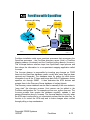
Understanding ForeView Management Processes
ForeView and Net Mgmt Systems
The Discovery and Status Daemon
Discovery Steps
The Discovery Server
Activity of fvdsd
Discovered Objects
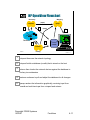
ForeView/OpenView Management Processes
OpenView Processes
Background Process
HP OpenView Flowchart
ForeView/OV Processes
ForeView with OpenView
Status Polling
OpenView Start-up and Shut-down
Handling Traps
Mapping
Mapping Basics
OpenView Status Colors
OpenView Map Levels
Root Map
IP Internet
ForeView Status Colors
ForeView-OpenView Maps
ATM Networks
ATM Switch Connections
HP-OV and NetView Only
Meta-Connections
Practice Lab - Map Levels
Lab Results
Practice Lab - ForeView's ATM Map
Page
2
3
4
5
6
7
8
9
10
11
12
13
14
15
16
17
18
19
20
21
22
23
24
25
26
27
28
29
30
32
Continued on next page
3
Table of Contents
Module 5
ForeView Configuration
Page
Product Licensing
ForeView Applications
ForeView Configuration File
Command Line Execution
Fvds Configuration
Fvds Options - Discover What?
Fvds Polling Options - How Fresh is Fvds' Data?
Custom Polling Lists
Discovery Problem
Preference Items
Fvmap Configuration - How Accurate is Fvmap?
Fvovmon Configuration - How Accurate is OVWDB?
Linking with OpenView
Module 6
ForeView Channel Tool, Graphing Tool, Inventory Tool
ForeView Channel Tool
Accessing the Channel Tool
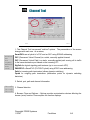
Channel Tool
Entering port info
The Browse Options Box
The VC Browser
SmartPVC
Practice Lab - Channel Tool
Practice Lab - Results
Trace Paths and Channels
Tracing Tool
Trace and Graph
Practice Lab - Trace Channels/Paths
Inventory Tool
The Inventory Tool
Inventory filters and Version History
Practice Lab - Inventory
2
3
4
5
6
7
8
9
10
11
12
13
14
Page
2
3
4
5
6
7
8
9
10
12
13
14
15
16
17
18
19
Continued on next page
4
Table of Contents
Appendix 1
Switch Network Troubleshooting Using ForeView
Problem Isolation
One Switch problems
Single Switch Concerns
Connected Pair of Switches Problems
All Switches Related to a Connection Problem
The ForeView Channel Trace Tool
All Switches Problem
Troubleshooting Configuration
Statistics Gathering
Statistics (port)
Port Graphing
Port Logging
Statistics (signaling)
Statistics (connection)
Working with TAC
ForeView TAClink
fvtaclnk form
Page
2
3
4
5
6
7
8
9
10
11
12
13
14
15
16
17
18
5
:HOFRPHWR)25(
6\VWHPV
)RUH9LHZ7UDLQLQJ
ForeView
10/16/97 P-1
Copyright FORE Systems
10/16/97
ForeView
P-1
,QWURGXFWLRQV
•
•
•
•
Name
Hometown
Current Occupation/Background
Class Expectations
ForeView
10/16/97 P-2
Copyright FORE Systems
10/16/97
ForeView
P-2
/RJLVWLFV
•
•
•
•
•
•
9:00 AM to 4:00 PM each day
15 minute break in AM
1 hour for lunch
15 minute break in PM
Rest rooms in lobby of this building
Phones
• Located in Customer Lounge
• Front desk phone number
• 412-742-7444
ForeView
10/16/97 P-3
Copyright FORE Systems
10/16/97
ForeView
P-3
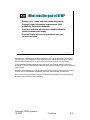
:KDWZDVWKHJRDORI$70"
• Satisfy voice, video and data networking needs
• Support larger information requirements with
potentially unlimited bandwidth
• Provide a solution which was scaleable without a
forklift swapout philosophy
• Provide Quality of Service guarantees on a per
connection basis
ForeView
10/16/97 P-4
Asynchronous Transfer Mode (ATM) as defined by CCITT at the time (now ITU) and later
the ATM Forum, was targeted from the beginning as the switching technology for a future
network that included support for three major forms of traffic (voice, data and video).
ATM’s bandwidth handling capability was (and still is) open-ended. SONET pipes were
proposed to connect ATM switches, and those pipes continue today to evolve into larger and
larger entities.
Scalability was designed into ATM, and the ATM Forum has been particularly keen recently
to insure a level of downward compatibility with each new technology enhancement.
One of the most important differentiators of ATM was also designed in from the beginning,
and that is per-connection QoS guarantees.
Copyright FORE Systems
10/16/97
ForeView
P-4
)25(·V9LVLRQ
7RGHOLYHUQHWZRUNVWKDW
HQVXUHWKDW\RXU
EXVLQHVVLVQRORQJHU
OLPLWHGE\ZKDWWKH
QHWZRUNZLOODOORZ
ForeView
10/16/97 P-5
Copyright FORE Systems
10/16/97
ForeView
P-5
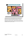
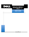
7KH([WHQGHG(QWHUSULVH
+LJK3HUIRUPDQFH0XOWL6HUYLFH,QIUDVWUXFWXUH
Human
Relations
Finance
Manufacturing
Accounting
Server
T1
To Internet
To
Suppliers
Web
Server
T1
T3
Engineering
Corporate T1
VPN
Engineering
Human
Relations
Finance
To
Distributors
Manufacturing
ForeView
10/16/97 P-6
Our goal is then to deliver the network components needed to model an extended enterprise
utilizing a high performance multiservice infrastructure.
Copyright FORE Systems
10/16/97
ForeView
P-6
7KH&RUHRIWKH1HWZRUN
• The Core determines what
applications the edge can
support
• An ATM-based core
provides the foundation for
• “Smart” Bandwidth
• MultiService
• Seamless Integration
of LAN and WAN
ATM
Core
ForeView
ATM
Edge
10/16/97 P-7
FORE’s Core is built on family of ATM switches including the ASX-1000, ASX-200BX and
LE-155 plus families of ATM network interface cards which support a variety of server or
workstation applications.
The elimination of the LAN/WAN “seam” is simply that a cell in the LAN is identical to a cell
in the WAN.
Copyright FORE Systems
10/16/97
ForeView
P-7
7KH$70,QWHJUDWHG(GJH
Voice
• Comprehensive
range of Edge
Solutions
• “Best in class” edge
performance
• Solutions Designed
for ATM Integration
FDDI
ATM
Core
Video
Frame Relay/
Circuit Emulation
ATM Workgroup
25/155
Ethernet
10/100
• Common ATM hardware
• Common ATM software
– ForeThought
• Common Management
– ForeView
ForeView
10/16/97 P-8
FORE’s Edge products include the PowerHub 6000/7000 product family, the ES-3810/3850
product family, the CellPath product family and our video over ATM product family.
Copyright FORE Systems
10/16/97
ForeView
P-8
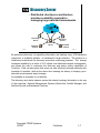
([WHQGHG(QWHUSULVH([DPSOH
Conventional
Departmental
LAN
ATM LAN Workgroup
(ATM to the Desktop)
FDDI
(ATM Edge switching)
FDDI Concentrator
PowerHub
7000
ForeRunner
ASX-200WG
ATM-attached Macs, PCs & UNIX Workstations
ATM LAN Backbone
(ATM Core switching)
10BaseT Hub
Server
ForeRunner ASX-200BX
Server
Ethernet-attached
PCs and Workstations
Conventional
LAN
Workgroup
(ATM Edge switching)
ES-3810
PowerHub
7000
ForeRunner ASX-200BX
ForeRunner ASX-200BX
Corporate Backbone
(ATM Core switching)
ATM
WAN
MCU
(video)
PBX
(voice)
ForeRunner
ASX-1000
CellPath
90 / 300
Ethernet-attached
PCs and UNIX Workstations
ForeView
Network
Management
(ATM Muxing/Concentrating)
ForeView
ATM Link
Ethernet
Fast Ethernet
FDDI
10/16/97 P-9
FORE Systems provides a complete Extended Enterprise solution including support for
conventional LAN connectivity (through ATM Edge switching) and ATM Core switching
which as shown above could include applications such as ATM to the desktop for
workgroups, ATM LAN Backbones and ATM Corporate Backbones. The Corporate
Backbone is often connected across the wide area and many times includes support for a
corporate-wide voice and/or video network. Together, the products represented performing
the applications shown above, provide a solution that solves today’s problems and lays the
foundation for tomorrow’s multi-service network.
Copyright FORE Systems
10/16/97
ForeView
P-9
3UH5HTXLVLWHV
• Completion of Core Switch or LAN
Certification course or comparable
experience with FORE’s ATM switch
products, specifically:
• Familiarity with AMI user interface
• Exposure to Device Manager software for
ATM switches and ES-3810
• Basic ATM networking concepts
• Basic IP networking concepts
ForeView
10/16/97 P-10
The scope of this class is coverage of SNMP-based management of FORE’s products.
Instructors assume knowledge of FORE’s products and use of element manager . IP
connectivity is a crucial issue in SNMP-based management and success of the labs will
depend on the student’s ability to take steps needed to initialize, manage and configure IP
interfaces on desktop systems and FORE’s ATM switches.
Copyright FORE Systems
10/16/97
ForeView
P-10
)RUH9LHZ&RXUVH$JHQGD
Day 1 - Product overview, installation,
licensing, SNMP basics and labs
Day 2 - Background and foreground
processes for discovery, mapping, NMS
integration, configuration of discovery and
NMS integration, mapping, and labs,
Channel and Tracer tools
Day 3 - Inventory, graphing, logging tools,
troubleshooting with ForeView and labs.
ForeView
10/16/97 P-11
Copyright FORE Systems
10/16/97
ForeView
P-11
7KH/DE/D\RXW5RRP
Paris
London
Door
Sydney
Rome
ForeView
10/16/97 P-12
The network facility that you have access to for this class includes enhancements to help
you maximize your learning efforts. The student-to-keyboard ratio is 1:1. Two basic ATM
desktop platforms are in the training room -- Unix (on Suns) and Windows NT (on
Compaqs). Throughout the course you will have ample opportunity to use both platforms. It
is to your advantage to switch between end nodes within your group to get firsthand
experience on both and to see the differences in features enabled on each platform.
The network equipment is clustered in racks. Naming conventions for the equipment is
based on names for each rack. London, Paris, Rome and Sydney are the rack names, so
the host names are simply Rome1, Rome2, Rome3, etc. With a maximum of four students
per rack, there should be ample opportunity to “do it yourself” on each lab. Watching
someone else execute a lab will not result in the same learning experience.
Copyright FORE Systems
10/16/97
ForeView
P-12
7KH/DE/D\RXW5RRP
Paris
Sydney
Rome London
ForeView
Door
10/16/97 P-13
Copyright FORE Systems
10/16/97
ForeView
P-13
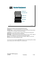
5DFNHG(TXLSPHQW
CellPath 90
PowerHub 7000
CellPath 300
Patch panel
ASX-200 BX
ES-3810
ForeView
10/16/97 P-14
Each rack may contain one of the following (starting at the top):
CellPath 90 - a T1 ATM interface supporting voice, video and data.
PowerHub 7000 - a routing, switching hub providing ATM connectivity, this PowerHub has
16 10BaseT ports, an ATM uplink, and dual power supplies.
CellPath 300 - a cell midplane multiplexer supporting various services including ATM.
Patch Panel - the point of all UTP wiring concentration.
ASX-200BX - a 2.5 Gbps ATM switch with 4 ATM 155 Mbps UTP ports, 6 ATM 1.5 Mbps T1
ports, 4 ATM 155 Mbps OC-3c multimode ports and dual power supplies.
ES-3810 - a low-cost Ethernet switch with 24 ports of Ethernet 10BaseT, one ATM 155
Mbps uplink, and a network management module.
The London rack also contains an ASX-1000 ATM switch with two switching fabrics (5 Gbps
total) containing several ATM 155 Mbps OC-3c multimode ports.
Copyright FORE Systems
10/16/97
ForeView
P-14
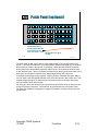
3DWFK3DQHORSWLRQDO
HOST SERIAL UTP
HOST ETH UTP
HOST ATM UTP
ASX ATM UTP
PH ETH UTP
ETH XVR
3810 ETH UTP
Multimode fibers
at each ASX-200 BX
(can attach up to
four at a time) from: ASX-1000, PH, 3810,
CP300
ForeView
10/16/97 P-15
The patch panel in each rack is there to make things easier to connect any device to any
device. Two Cat5 UTP cables are run from each host (Ethernet and ATM UTP ports) to the
ports marked as “Host” in the top row of connectors. Below the Host ATM UTP ports are
device ports for the ASX-200BX, PowerHub and ES-3810. These ports are wired to ports
on the named devices. There is an Ethernet crossover built into the panel at the lower left, to
allow easy interconnection between racks using straight through UTP cable runs.
To facilitate connecting the racks together, a duplex strand of multimode fiberoptic cable is
run from each of the ASX-200BX switches to the ASX-1000 switch in the London rack. Also,
multiple straight through UTP cables may be run between racks on the same side of the
room to facilitate certain lab exercises.
The intent is to allow simultaneous use of the Ethernet and ATM ports on the hosts and anyto-any ATM virtual connections. The hosts can be connected by use of the patch cords.
The local ASX-200BX can participate in a larger ATM network or isolate itself by using the
provided fiber.
Copyright FORE Systems
10/16/97
ForeView
P-15
2YHUYLHZRI)RUH9LHZ
$701HWZRUN
0DQDJHPHQW6\VWHP
ForeView
10/3/97 1-1
Copyright FORE Systems
10/3/97
ForeView
1-1
)RUH9LHZ2YHUYLHZ
• ForeView Network Management software
provides a complete solution for managing
ForeRunner ATM networks through a variety
of network management environments
ForeView
10/3/97 1-2
There are many industry standard network management systems that allow
network managers to manage and monitor legacy LANs, WANs, and MANs.
These products are mostly protocol-centric using protocols such as IP, IPX,
and AppleTalk. They support a a number of different topologies such as
Ethernet, Token Ring, and FDDI and Frame Relay.
The ForeView Network Management system is part of FORE Systems
ForeThought product line and is used to specifically manage and monitor
ATM networks. Although ForeView manages the network using the IP
protocol, it does not manage the IP network itself and leaves those functions
to programs such as Hewlett Packard OpenView, IBM NetView and Sun Net
Manager.
ForeView is written to work integrally with these IP network management
systems or to function as a stand-alone management system. In either
form, only FORE Systems’ devices are managed. under native operating
systems such as SunOS, Solaris, HP-UX, IRIX, AIX, and Windows NT.
Copyright FORE Systems
10/3/97
ForeView
1-2
*UDSKLFDO,QWHUIDFH
• The graphical interface provides a quick
visual assessment of:
• the state of ForeRunner switches (to portlevel)
• connection status
• diagnosis tools in the event of errors
• Available in integrated and standalone forms
ForeView
10/3/97 1-3
ForeView is designed to operate under graphical environments including
Sun OpenWindows, CDE and Windows NT. The ForeView program is
actually a number of components that allow the network manager to
evaluate the ATM network topology, inventory the ATM devices, execute
element configuration and management, and graph and trace traffic through
the network.
The base set of “tools” are available under a number of operating systems
and all look and function the same way.
When the workstation utilizes an NMS (Network Management System) such
as HP OpenView, IBM NetView or Sun Net Manager, ForeView will take
advantage of the NMS’ Event Logs and Error Trapping, Graphing modules,
Topology Managers, Threshold Programming and User Defined Functions.
These are the “integrated” versions of ForeView. If you are already familiar
with one of these NMS platforms, ForeView blends naturally.
The Standalone version of ForeView provides its own mapping, graphing
and logging utilities. The look and feel of this version is unique and provides
all the necessary functions.
Which is “better”? That’s completely up to the user, and sometimes the task
at hand.
Copyright FORE Systems
10/3/97
ForeView
1-3
)RUH9LHZ2QOLQH+HOS
ForeView’s
context-sensitive
On-line Help is now
in HTML format.
Any browser
supporting frames
can be used.
ForeView
10/3/97 1-4
The Help files in ForeView are context-sensitive and are in HTML format.
they include not only text but many images and screen shots that can be
viewed directly through a browser program that supports frames.
Most of the user manual is located in this searchable, on-line resource.
Copyright FORE Systems
10/3/97
ForeView
1-4
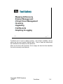
7RRO*DOOHU\
• Mapping & Discovery
• Element Management
• Virtual Circuit Management
• Inventory
• Upgrading
• Call Records
• Graphing & Logging
ForeView
10/3/97 1-5
ForeView’s list of tools is always growing. Of all that’s available, the list
above are the most “popular” among users. That is, these are what would
be considered core functions of the products.
More can be done with ForeView, this is simply the short list that identifies
the most commonly used features.
Copyright FORE Systems
10/3/97
ForeView
1-5
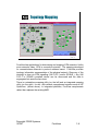
7RSRORJ\0DSSLQJ
ForeView
10/3/97 1-6
ForeView has applications for discovering and mapping ATM networks. Unlike
most networks today, ATM is connection-oriented. The mapping developed
for connectionless networks is protocol address based. ForeView provides
topology information representative of the physical network. Discovery of the
topology is done via ATM signalling (UNI 3.0/3.1 and/or SPANS ). Any UNI
3.0/3.1 or SPANS compliant device can be discovered and the data is
segregated into specific map views.
There is a standalone mapping utility (on the left) and an integrated mapping
utility (on the right) for use with network management systems such as HP
OpenView (shown above). In integrated platforms, ForeView complements
rather than replaces the existing NMS.
Copyright FORE Systems
10/3/97
ForeView
1-6
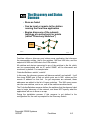
'LVFRYHU\6HUYHU
• Distributed client/server architecture
provides scalability required for
managing large switched internetworks
Discovery
Server
ForeView
X Client
Discovery
Server
ForeView
Server
ForeView
ForeView
X Client
10/3/97 1-7
By performing discovery via signalling information and seeking every ATM backbone
component, a scalability problem is introduced in larger networks. The solution is a
client/server architecture for discovery and status monitoring purposes. This change
increases scalability by a factor of 5-10, allows true distributed network management,
and allows the user to customize the discovery and status polling capabilities of
ForeView. Field use has shown that users can now effectively manage networks with
hundreds of switches, while at the same time lowering the latency in keeping up-todate with actual network status changes.
As scalability is increased, so is flexibility.
The discovery and status daemon serves the network topology information to the any
of the supported Network Management Systems (OpenView, SunNet Manager, and
NetView) as well as Standalone ForeView.
Copyright FORE Systems
10/3/97
ForeView
1-7
'HYLFH0DQDJHUV
• Graphical, point-and-click device
configuration and status monitoring
at the device level for ATM switches,
PowerHubs, and LAN Access
switches
ForeView
10/3/97 1-8
The Device Manager provides an intuitive, graphics-based interface for device
management. A photo-like image of the device in question allows users to easily
configure and monitor the device using simple point-and-click operations. Users can
configure the full complement of OC12, OC3, DS3, DS1, E3, E1, and J2
parameters. Configure NSAP addresses, Distributed Timing and Netmod Buffer
allocations. Turn Signaling On/Off (SPANS, UNI3.0/3.1) per port. A Tachometer can
be displayed below each port to provide a visual assessment of traffic on a per port
basis (input/output utilization, queue loading, or input/output reservation).
Device Manager supports ASX-1000s. The main view summarizes all fabrics in the
enclosure, major and minor alarms for ports, links and alarms for environmental
traps (Power Supplies, Overtemp Sensor, 4 Fan Banks).
ForeView includes Device Manager support for the ES3810, ES3850, and
PowerHub in addition to the ASX ATM Switch products.
Copyright FORE Systems
10/3/97
ForeView
1-8
9LUWXDO&LUFXLW0DQDJHPHQW
• Channel Tool consolidates all Path and
Channel management
• Permanent Virtual Circuits (PVCs)
• Smart PVCs (SPVCs)
• Policing contracts
• Virtual Paths (VPs)
• Signaling Paths (SigPaths)
ForeView
10/3/97 1-9
ForeView allows the user to create and modify VC’s through a simple and
efficient “channel tool”. This tool is a dialog box that allows a single point of
entry of port information, user-selected Virtual Path Identifier (VPI), Virtual
Channel Identifier (VCI), reserved bandwidth, direction, and any Usage
Parameter Control (UPC) contract to be used. The user can browse existing
virtual circuits and even filter the circuits to be shown. A unique feature in
ForeView allows the user to trace the route of a specific circuit through a
number of switch hops.
A browsing function permits the inspection of particular path and channel
types on a switch to speed monitoring and control without working through
long lists.
Copyright FORE Systems
10/3/97
ForeView
1-9
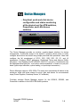
,QYHQWRU\DSSOLFDWLRQ
• The inventory tool allows managers
to gather and track equipment
information from switches, edge
devices, and adapters.
• Provides managers with a facility to
develop upgrade strategies and filter,
sort, and report on device
configurations and addresses.
ForeView
10/3/97 1-10
The inventory tool provides managers with strategic information about all the
FORE switches, end devices, and host adapters within ATM network.
For example, a manager could query the network to provide a report of all
ASX-200BX switches that had the ForeThought 4.0 operating system. This
would allow an efficient strategy to be developed for the upgrade to
ForeThought 4.1 or newer switches.
The tool gives network managers a tabular view of all the FORE ATM
equipment in your network, including information such as model number,
serial number, software version number, IP address, and logical name and
version history of ForeThought software running on your ATM switches.
Version history can be stored as a file for offline use.
Copyright FORE Systems
10/3/97
ForeView
1-10
6RIWZDUH0DQDJHU
• Global software
upgrades with a
single point-and-click
operation
• Simplifies and
accelerates the
process of
downloading new and
upgraded software
across the enterprise
ForeView
10/3/97 1-11
ForeView Software Manager greatly simplifies the process of downloading
new and upgraded software across the enterprise.
This feature complements the functionality provided by ForeView Inventory by
allowing the user to perform remote software upgrades to ATM switches
globally or selectively.
Copyright FORE Systems
10/3/97
ForeView
1-11
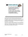
&DOODQG3HUIRUPDQFH
5HFRUGV
• Call Records foundation for
accounting and billing
applications
• Performance Records foundation for
trending, capacity
planning
• Distributed data
collection provides
scalability
ForeView
ForeView
files are
sent via ftp
at user
configurabe
intervals
10/3/97 1-12
These two unique features address scalability and proactive management. Call
Records collects information on a ‘call’ basis (VC and VP level) whereas
Performance Records collects port activity information.
Call Record information can be used to generate accounting and billing reports,
whereas Performance Record information can be used to perform trend analysis,
capacity planning, and performance modeling.
Instead of using a polling-based architecture for collecting this information, Call
and Performance Record information is collected locally on the switch, greatly
distributing the management load. The collected data is transferred at user
configurable intervals from the switch to a data collection server where ForeView
can convert it from binary to ASCII file format.
Call Records provides a comprehensive list of over 40 variables for each call,
including start time of the call, duration of the call, source and destination NSAP
addresses, etc.
Performance Records provide detailed performance and error statistics on all
interfaces including OC3, OC12, DS1, DS3, E1, E3, and J2 netmods. Users can
also configure the amount of memory allocated to record collection and specify a
primary and secondary server to upload the records to for redundancy.
Copyright FORE Systems
10/3/97
ForeView
1-12
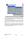
*UDSKLQJ7RRO
Example:
Transmitted
cells per
second on two
switch ports
ForeView
10/3/97 1-13
The ForeView graphing tool displays graph statistics on ports, virtual
channels, virtual paths, or hosts.. The collection interval is user selectable
and can be different for each graph. The display width, represented in
minutes, is user selectable as well.
ForeView Grapher enables users to graph statistics including transmit and
receive cell counts. Additional statistics are available depending on what type
of interface is involved.
Copyright FORE Systems
10/3/97
ForeView
1-13
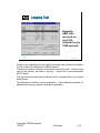
/RJJLQJ7RRO
Example:
UBR cells
received on
port 1A4,
collected every
1800 seconds
ForeView
10/3/97 1-14
Similar to the graphing tool, the logging tool writes the collected information
to a file. Users can choose the collection Interval.
Transmit and receive utilization is recorded in raw cell counts. These counts
can be per channel, per path or per port. Output file is comma-delimited
ASCII format.
The log can be launched from pull-down menus, command line or port status
dialog boxes.
The delimited information can be exported to other software programs for
additional processing, analysis, and report generation.
Copyright FORE Systems
10/3/97
ForeView
1-14
)RUH9LHZ$UFKLWHFWXUH
Tools
Bridging configuration
Graphing
Routing configuration
Logging
Filtering
Channel Tracing
Discovery/Topology
Call Records
Inventory Manager
Event/Fault management
Software Manager
MIB collection
and more...
Path/Channel management
QoS provisioning
NMS
SNM
O/S
Solaris
HP/OV
NetView/AIX
HP/UX
Standalone
IBM AIX
Win/NT
Irix
SNMP
Managed
Devices
ASXs
CellPaths
ES38xx
ForeView
PowerHubs
10/3/97 1-15
ForeView can be viewed as a simple layered architecture as shown in the upper half of
the diagram. ForeView communicates with FORE’s products using SNMP. ForeView
software can reside on either Unix or a WinNT operating system, and depending on
which OS is chosen, the user can then choose to run ForeView in standalone mode or
in conjunction with some of the industry’s most popular Network Management Systems
(NMS) as shown. Please refer to the ForeView Web page for latest version numbers.
ForeView is designed to manage all of FORE’s products from a single unified
application. We’ve listed just some of the key tools within ForeView used to manage the
various networking products. Some tools are device specific, such as or the
Path/Channel Tool that works only with ATM switches and routing configuration works
only with PowerHub. Some tools work at a network level, such as discovery/topology,
graphing, and logging.
Copyright FORE Systems
10/3/97
ForeView
1-15
0DQDJHPHQW0RGHV
• All products can be managed via textbased user interface (telnet and/or serial
connection)
• All products have a subset of
management capability accessible via
ForeView
ForeView
10/3/97 1-16
Since some users do not employ SNMP-based network management, all
products have a simple command-line or menu-driven user interface. these
interfaces are accessed through the product’s serial port or via a telnet
session.
SNMP-based management tools such as ForeView
management capability via an alternate interface.
provide
that
The question left to be answered is: When to use which mode?
Copyright FORE Systems
10/3/97
ForeView
1-16
0DQDJHPHQW0RGHV
■
Command or Menu interfaces:
• Full command-driven interface with on-line help
• Initial configuration of switch IP address, subnet masks,
and routing
• Restarting, upgrading, and backing up switch software
■
ForeView (Graphical Interface):
•
•
•
•
•
•
Mapping and monitoring network
Network Event log and Threshold events
Net Mod/Port monitoring and configuration
Setting up and browsing PVCs, PVP’s, and SPVCs
Monitoring and Configuring UNI and SPANS Signaling
Tracking, logging, and graphing usage and errors over
time
ForeView
10/3/97 1-17
Certain procedures are necessary at the initial setup of the switch - setting
the IP address of an interface, setting subnet masks and routing, or certain
system maintenance tasks. Certain commands are better to keep as
command line and not “point and shoot” to avoid the ease of detrimental
mistakes (like the initialization of the flash file system or resetting of the
configuration database).
These tasks, at least, ought to be executed
through the command or menu interface.
Other complex command-line procedures like the creation of a non-zero
Virtual Path and its virtual channels and QoS (Quality of Service) functions
are much easier through a dialog box in ForeView. The nature of a graphical
user interface makes it easier to initialize graphs, topology maps, and
bitmaps representing device status.
It is important to remember that ForeView only manages switches and edge
devices and not the host or host adapter.
The bottom line usually is: Do what works best for you.
Copyright FORE Systems
10/3/97
ForeView
1-17
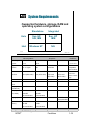
6\VWHP5HTXLUHPHQWV
• Supported hardware, storage, RAM and
operating system configurations
Standalone
Integrated
Unix
Sun, HP,
SGI, IBM
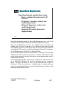
Sun, HP
IBM
Intel
Windows NT
N/A
ForeView
10/3/97 1-18
Sun
Microsystems
Hewlett-Packard
Silicon
Graphics
IBM
Operating
System
Solaris 2.4 or
2.5.x
HP-UX 10.01 or IRIX 5.3
10.10
AIX 4.1
Supported
platform
SPARCstation
10 or higher
HP9000, Series MIPS R4000 RS/6000
700
machines
Network
interface
Ethernet or ATM Ethernet or ATM Ethernet or
card (SBA-200) card (HPA-200) ATM card
(GIA-200)
Ethernet or
ATM card
(MCA-200)
Intel
Platforms
W indows NT
3.5.1 or 4.0
IBMcompatible
with Pentium
Ethernet or
AT M card
(ESA- or PC A200)
Monitor
Color
Color
Color
Color
1024x768
Available disk
space
32 MB min.
32 MB min.
32 MB min.
130 MB min.
100 MB min.
Swap space
(standalone)
64 MB min.
64 MB min.
64 MB min.
64 MB min.
N/A
Swap space
96 MB min.,
N/A
N/A
N/A
(OV, SNM)
128 MB
recommended
96 MB min.,
128 MB
recommended
Paging space
N/A
N/A
N/A
System
memory
32 MB min.
64 MB
recommended
32 MB min.
64 MB
recommended
64 MB min.
192 MB
N/A
recommended
64 MB min.
64 MB min.
Copyright FORE Systems
10/3/97
ForeView
1-18
2YHUYLHZRI6103
ForeView
9/15//97 2-1
Copyright FORE Systems
9/15/97
ForeView
2-1
6103%DVLFV
• Network Management Architecture
• IP Connectivity
• MIB Variables
• Community Strings
• SNMP PDUs
ForeView
9/15//97 2-2
This is not intended to be a comprehensive treatment of SNMP. Rather, it is
intended to address the basic operating model for SNMP and then address
some specific aspects that should be of particular use for understanding and
retaining the rest of this network management curriculum.
Copyright FORE Systems
9/15/97
ForeView
2-2
1HWZRUN0DQDJHUDQG
$JHQWV
Client
(Manager)
Server (Agent)
Network Manager
FORE
SYSTEMS
ForeRunner ASX-200BX
C
A
RX1
RX2
RX3
RX4
RX1
RX2
TX1
TX2
TX3
TX4
TX1
RX1
RX2
RX3
TX1
TX2
TX3
RESET
RX3
RX4
TX2
TX3
TX4
RX4
RX1
RX2
RX3
RX4
TX4
TX1
TX2
TX3
TX4
D
B
ASX200BX
SER
ETH
NEXT SEL ECT
Router
Host
Server
(Agent)
Server
(Agent)
ForeView
9/15//97 2-3
The model SNMP employs to provide network management capability is the
familiar client/server model. It is a significant departure from the common
form of client/server in the client-to-server ratio.
Most client/server implementations have a small number of servers
compared to the number of clients. For example, a client/server mail
application based on the SMTP (Simple Mail Transfer Protocol) could have
hundreds, even thousands, of clients and only a few servers. A similar ratio
is common with file server applications.
Network management using SNMP inverts this ratio. SNMP clients are
management stations while every manageable device is a server. When
you consider how many hubs, switches, routers, multiplexers, etc. might be
in a corporate network, you can see this architecture does not follow a
typical client/server model.
Some alternate language is used in this case. Clients are often referred to
as managers and the many servers as agents.
Copyright FORE Systems
9/15/97
ForeView
2-3
(OHPHQWVRID1HWZRUN
0DQDJHPHQW$UFKLWHFWXUH
Management
System
(the manager)
Management
Application
(or Process)
Managed
System
(the agent)
Queries or
Commands
Agent
Process
Managed
Objects
Responses
Responses
Management
Database
& MIBs
MIB
Objects
Commands
Traps/Notifications
ForeView
9/15//97 2-4
The Management System is any network management platform. A very
simple platform would be a Unix workstation using a command-line “snmpwalk-like” function. A more sophisticated example would be the same
workstation running HP OpenView Network Node Manager, Sun
NetManager or IBM’s NetView/6000 Network Management software.
The Managed System is any network device that responds to and issues
snmp messages. For example, a Unix workstation that runs the snmpd
process could be a managed system. Let’s clarify the nomenclature.
Management System = Manager = Client
Managed System = Agent = Server
The messages exchanged are:
Queries/Commands - requests sent from the manager to the agent to get
information or alter system parameters.
Responses - the messages an agent sends in reply to queries or commands
sent by the manager.
Traps/Notifications - unsolicited information coming from the agent to the
manager. Usually to alert of a status change or problem.
MIBs are shown in the diagram. They are an important component and will
be covered shortly.
Copyright FORE Systems
9/15/97
ForeView
2-4
7KH26,0RGHODQG6103
Application
Presentation
Session
Transport
Mgmt. Application - SNMP PDU
Structure - ASN.1 and BER
Authentication - SNMP header
UDP
Network
IP
Data Link
Network dependent - SDU
Physical
Network dependent - interface type
ForeView
9/15//97 2-5
SNMP maps to the ISO 7-layer model for networking as follows:
Application - could be any program capable of creating SNMP PDUs.
General
OpenView, Sun NetManager
Specific
ForeView, MIB walker
Presentation - proper structuring of the information using a subset of ASN.1
Session - version and community string insertion/authentication
Transport - typical UDP transfer, uses port 161 (except trap messages port 162)
Network - Typical IP datagram
Datalink - any datalink supporting IP
Physical - any interface supporting IP
Copyright FORE Systems
9/15/97
ForeView
2-5
$SSOLFDWLRQ/HYHO0DQDJHPHQW
• Requires connectivity at various levels
• Physical
• Protocol
• Good News:
Can be standardized across platforms
and network types
• Bad News:
Networks may not always be up
ForeView
9/15//97 2-6
As SNMP is an application level form of management, connectivity is
assumed. We know that such an assumption can be dangerous. So why
use application level management?
Many reasons could be stated, but foremost is the ability to manage devices
connected by nearly any kind of network infrastructure. The management
station is likely to be directly connected to only one or perhaps two network
types. For example, a management station connected via FDDI and
Ethernet would not be uncommon. This limited connectivity does not limit
the station’s ability to monitor and control devices connected via Frame
Relay, ATM, X.25 or any other network type that is capable of supporting IP
traffic. Application-level network management then need not influence the
kind of networks deployed.
As networks go, however, there are periods when connectivity is broken and
parts of the network are unreachable. This can be limited by proper network
planning, but it is unlikely to be eliminated entirely. The price of a robust
network may be too high for some network operators. In these cases, the
likelihood of downtime is greater.
Every network manager must balance the cost of network fault tolerance
against his need to monitor and control the network elements.
Copyright FORE Systems
9/15/97
ForeView
2-6
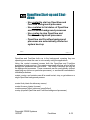
,3&RQQHFWLYLW\
• Because SNMP is an application level
manager, it requires that there be IP
connectivity to the destination to
manage the destination
• If you can’t “ping” the destination,
SNMP will not work (Debugging Tip #1)
• If name services or complex routing are
used, they must be configured correctly
(Debugging Tip #2)
ForeView
9/15//97 2-7
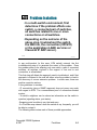
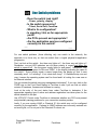
One of the pre-requisites for performing SNMP-based management is IP
connectivity with the network elements. This may sound simple and obvious,
but the statistics say that most network downtime comes from low-level,
simple problems. The irony is that these problems are exactly what network
management is implemented to help resolve. Yes, a network symbol can go
red on a net management map, but that only informs the network operator
the device cannot be contacted. It doesn’t say why it cannot be contacted.
With this simple concept in mind, please be aware FORE System’s TAC
reports the most frequent source of problems with ForeView is IP
connectivity. The IP basics (address, mask, and gateway information) are
often the culprits in a trouble call. Some more advanced IP issues can be at
fault, such as name resolution services and routing problems.
Keep in mind the SNMP application can only report on the network as seen
from the NMS’s perspective. Something as simple as a typographical error
in a hosts file can give the appearance some of your network is unreachable.
Because there are many reasons a device might be unreachable or nonresponsive, the device should not be assumed to be down or malfunctioning
when the NMS loses contact with it.
Copyright FORE Systems
9/15/97
ForeView
2-7
0DQDJHPHQW,QIRUPDWLRQ
• A hierarchical database of network
management information
• Logical organization is called SMI
• Information on the individual objects is
contained in the Management
Information Base (MIB)
ForeView
9/15//97 2-8
A portion of the SNMP specification indicates how to represent network
information and what it means to the administrator. This information is kept
in a database format.
To allow interoperability of many different kinds of management applications,
the information is in a tree-like structure defined in the Structure of
Management Information, or SMI.
A hierarchy is defined, logically dividing the information to provide a path and
location for variables in the database. Abstract Syntax Notation 1 (ASN.1)
and Basic Encoding Rules (BER), specified in SMI, are used to define the
database contents. ASN.1 encodes a) integer, b) octet string, c) object
identifier and d) null variable types for use in SNMP message exchanges.
This is an object-oriented database, so each node in the tree structure has
an identifier for that object. This is called the Object Identifier or OID.
An OID then is a unique location for storing or retrieving values. The
Management information Base (MIB) is the resulting database where objects
are addressed, named and defined for the managed device.
Copyright FORE Systems
9/15/97
ForeView
2-8
0,%6WUXFWXUH
• Tree Structure beginning at the root
• Branches organize objects by categories
• MIB represents the managed objects as
leaves on the branches
• Public and private MIBs are defined
ForeView
9/15//97 2-9
The OIDs for all managed devices begin at the root. Descending into the
hierarchy, categories are encountered until managed objects are reached.
For instance, the interface status for a particular device may be a simple
binary value (up or down), but to get to that value requires you to go through
increasingly specific categories. This permits adds and changes to the MIB
without affecting the structure of the existing objects.
MIBs have been defined for public and private use. Public MIBs would be
for objects common to many devices. For example, Ethernet, IP and DS-1
MIBs are available for anyone to use if their devices have need of such
support. This enables off-the-shelf management products to know how to
query anybody’s product with an Ethernet, IP or DS-1 interface.
Private MIBs are created by the device’s maker. For instance, an Ethernet
switch might have an LED indicating excessive collisions on that port. The
status of this LED would not be in the public Ethernet MIB because not all
Ethernet products have such an LED. The makers of that switch would
define the LED’s status into the private portion of the MIB structure.
Copyright FORE Systems
9/15/97
ForeView
2-9
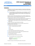
7KH,QWHUQHW2,'7UHH
root
ccitt (0)
joint-iso-ccitt
(2)
iso (1)
org (3)
dod (6)
internet (1)
directory
(1)
mgmt
(2)
experimental
(3)
mib (1)
1.3.6.1.2.1...
private
(4)
enterprises
(1)
1.3.6.1.4.1...
vendors...
ForeView
9/15//97 2-10
Moving to the actual structure, this diagram shows the root in the upper left.
There are three choices from the root. CCITT (now the ITU), ISO and joint
categories are the only choices. A new category (3) could be added without
affecting any of the others.
The representation of an OID is done in a dotted notation that is as short or
long as it needs to be to indicate the proper place on the tree.
In the example on the lower left, public MIBs share the prefix 1.3.6.1.2.1.
The ellipsis indicates that object is still only a category, more definition is
needed to reach an actual managed object.
The example on the lower right is the OID prefix found for vendor-specific
products. The OID 1.3.6.1.4.1 is followed by the vendor’s registered number.
For FORE Systems, most of the products are defined under 1.3.6.1.4.1.326.
Copyright FORE Systems
9/15/97
ForeView
2-10
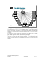
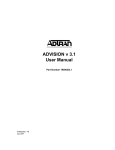
7KH0,%6HFWLRQ
1.3.6.1.2
system (1)
character
(19)
mib (1)
interfaces
(2)
decnetP4
(18)
address
translation (3)
bridge (17)
ip (4)
rmon (16)
icmp (5)
bgp (15)
tcp (6)
ospf (14)
udp (7)
transmission
(10)
egp (8)
oim (9)
snmp (11)
ForeView
appletalk
(13)
generifIF
(12)
9/15//97 2-11
In the MIB section (1.3.6.1.2.1), 19 categories exist. For an Ethernet switch
product, the system, interfaces, IP and bridge MIBs may be the only ones
supported. A similar product could also implement the TCP and UDP MIBs,
if needed.
A multiprotocol router would likely implement more MIBs such as ICMP,
EGP, SNMP, appletalk, OSPF, BGP and DecnetP4 MIBs.
The point is, there are many choices available. The implementor must
decide in advance what will be manageable and choose or create the MIBs
needed.
Copyright FORE Systems
9/15/97
ForeView
2-11
&RQWHQWVRIPLE
• Has system definitions (Contact,
name, uptime, etc.)
• IP statistics (fragments sent, discards,
etc.)
• TCP statistics (segments sent, etc.)
• interface statistics (name, MTU, MAC
address, etc.)
ForeView
9/15//97 2-12
Because it is a public MIB, not specific to any manufacturer, the managed
objects are those common to any type of product.
Copyright FORE Systems
9/15/97
ForeView
2-12
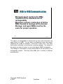
0,%WR0,%&RPPXQLFDWLRQ
• Managed agent contains the MIBs
required for the intended level of
manageability
• Managers contain a collection of all the
MIBs needed to manage all the devices
• Manager and agent MIBs must be the
same for proper operation
ForeView
9/15//97 2-13
The degree of manageability is determined by how much information the
agent stores in its MIB. You can have a multiprotocol router that doesn’t
implement the ip MIB, for example. It will route IP traffic, but it can’t have
that function controlled or monitored by a remote manager. The makers of
the device can make all, some, or none of the device SNMP manageable.
The manager is responsible for having all the MIBs for all the products in its
management domain. That may mean MIBs from a number of different
manufacturers.
Copyright FORE Systems
9/15/97
ForeView
2-13
&RPPXQLW\6WULQJV
• SNMP provides limited security
• Read-only “password”
• Read/Write “password”
• Not-encrypted
• Defaults to public/private
ForeView
9/15//97 2-14
Since the SNMP relationship is connectionless, it needs some form of
authorization so the agent can be sure the sender is a manager who is
supposed to manage him and deserves a response. This authorization is
included every SNMP message, not just the initial ones. The term
community string refers to the characters used to identify a group of devices
in a management domain.
While not as secure as a user or session-type password, the community
string idea divides the conversations by function. A read-only string is
configured for queries, a read-write string is used for control functions.
The string is not at all secure. Anyone with a sniffer on a LAN segment
could trap SNMP frames and discover the community strings in use. There
are defaults for these, “public” for read-only and “private” for read-write. But
in this day of internet connectivity no one should leave the strings alone on a
manageable device.
This is, in part, the price for simplicity for something as complex as network
management.
Copyright FORE Systems
9/15/97
ForeView
2-14
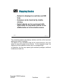
8VH2I&RPPXQLWLHV
• Allows more than one NMS to have
control (easy management access)
• Allows segregation of management
duties (scalability)
NMS
NMS
NMS
ForeView
9/15//97 2-15
The community is not supposed to be a secured area, rather it’s an area of
management shared by managers and agents.
The managers on the left show that two communities can be managed by
multiple stations--even when the communities themselves have no interconnectivity. Each of these two managers would need to know the strings in
each community and which IP addresses are associated with each
community.
The network of the middle community is so large two distinct communities
are established, even though they are one network. The manager on the
right would not know how to reach the devices in the middle. Even if it
discovered their IP addresses, no SNMP communication would be
established because the community authentication would fail.
Copyright FORE Systems
9/15/97
ForeView
2-15
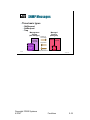
61030HVVDJHV
• Three basic types
• GetRequest
• SetRequest
• Trap
Management
System
(the manager)
Management
Application
(or Process)
Managed
System
(the agent)
Queries or
Commands
Agent
Process
Managed
Objects
Responses
Responses
Management
Database
& MIBs
MIB
Objects
Traps/Notifications
ForeView
9/15//97 2-16
Copyright FORE Systems
9/15/97
ForeView
2-16
*HWDQG6HW3'8V
Version
PDU
Type
Community
GetRequest, GetNextRequest,Get Response,
or SetRequest PDU
Error
Status
Object 1, Value 1Object 2, Value 2
Request
ID
Error
Index
...
Variable Bindings
ForeView
9/15//97 2-17
PDU Type:
GetRequest
0
Set Request
3
GetNextRequest
1
Trap
4
GetResponse2
Request ID: Integer that correlates the managers request and the agents
response. Analogous to TCP segment numbers
Error Status: Integer field identifies the entry within the variable bindings list
which caused the error.
Error Index:
noError
0
badValue
3
tooBig
1
readOnly
4
noSuchName
2
genErr
5
Variable Bindings List: the list of variables and their values. The object is
the OID encoding of the object plus the instance for the variable being
communicated. The value is the desired (setRequest) or actual (Get
Request) value for the object.
Copyright FORE Systems
9/15/97
ForeView
2-17
7UDS3'8
Version
PDU
Type
Community
Enterprise
Trap PDU
Agent Generic Specific
Object 1, Object 2,
Timestamp
Address Trap Type Trap Type
Value 1 Value 2
...
Variable Bindings
ForeView
9/15//97 2-18
PDU Type : Traps = 4
Enterprise: OID prefix of the enterprise sending the trap
(1.3.6.1.4.1.326 would indicate FORE Systems)
Agent Address: IP address of the agent.
Generic Traps:
Value
Type
Value
Type
0
coldStart
4
authenticationFailure
1
warmStart
5
egpNeighborLoss
2
linkDown
6
enterpriseSpecific
3
linkUp
If a non-generic trap has occurred (Generic Trap Type = 6), it will be further identified in
the Specific Trap Type Field and the Enterprise Field.
Timestamp: contains the value of the sysUpTime object indicating the amount of time
elapsed between the last (re-) initialization of the agent and the generation of that trap.
Variable Bindings List: the list of variables and their values. The object is the OID
encoding of the object plus the instance for the variable being communicated.
Copyright FORE Systems
9/15/97
ForeView
2-18
6XPPDU\
• For Network Management to work you
need to:
• Have IP Connectivity
• Have Correct Community Strings
• Know what MIBs have been implemented
• SNMP is simple because there are only
a few commands
ForeView
9/15//97 2-19
Copyright FORE Systems
9/15/97
ForeView
2-19
,QVWDOODWLRQRI
)RUH9LHZ
10/897 3-1
ForeView
Copyright FORE Systems
10/8/97
ForeView
3-1
3UHLQVWDOODWLRQ
• Before beginning the installation, the
user must have a temporary or
permanent license key and at least
one switch name in the ATM cloud to
begin discovery
• Users may need to adjust the
ForeView configuration file
ForeView
10/8/97 3-2
The ForeView license file is sent along with the program media packet.
The user will receive a temporary key which is designed to expire within a 90
day period. During this time, the user can call FORE TAC and request a
permanent license that is “locked” to the IP address of the workstation that
will be running ForeView. If the IP address changes, FORE TAC must be
contacted to send out a new key for the new address.
The configuration file is a template of configuration settings that can be
altered for specific ATM network needs. To make things easier for the user,
the configuration file acts as a template with all resource variables described
and “remarked”. To change a variable, the user simply adjusts the resource
variable information and “unremarks” specific lines using their favorite text
editor.
Copyright FORE Systems
10/8/97
ForeView
3-2
6RIWZDUH,QVWDOODWLRQ
3UHSDUDWLRQ
• New installations should be installed
after installing OpenView, SNM, or
NetView programs.
• ForeView is available via ftp or CDROM media
ForeView
• Note: If you are already running a
previous version of ForeView in a
UNIX system, you need to “uninstall”
the previous version of ForeView by
running the remove.sh script.
10/8/97 3-3
Before any installation of ForeView products, make sure that any network management
systems such as HP OpenView, SunNet Manager, or IBM NetView/AIX are installed and
functional. The ForeView installation program will load and configure appropriate files
into the NMS file systems.
It is recommended to remove previous versions of ForeView before installation of the
new version. FORE has provided a script called remove.sh that will delete the older
version.
Before running the script, do the following:
Exit all ForeView applications.
Exit your network management system (HP OpenView or SunNet Manager).
If ForeView is installed in an alternate directory, make sure that the environment variable
FOREVIEW_HOME is set.
If ForeView is installed in an alternate directory it is imperative that you set the
FOREVIEW_HOME environment variable before you begin the removal to avoid
problems during the procedure.
NOTE:
ForeView assumes a default location of /usr/fore/foreview, but the Sun
workstations in our lab use the alternate directory /usr/local/foreview.
Copyright FORE Systems
10/8/97
ForeView
3-3
7R8VHUHPRYHVK
• Log in as root.
• We recommend that you save your
existing configuration and license
files. To do this, issue the following
commands:
• cp /usr/local/foreview/conf/foreview
/tmp/foreview
• cp /usr/local/foreview/conf/license
/tmp/fvlicense
• Issue the following commands:
/bin/sh /usr/fore/foreview/install/remove.sh
ForeView
10/8/97 3-4
After following the steps (above) to remove the older version, you are now
ready to install the latest version of ForeView. The software installation
instructions have been divided into two sections, installation procedures for
Unix platforms and for the Windows NT Stand-alone platform. Please
proceed to the installation instructions for the platform you are using.
All users of ForeView on the OpenView platform must be informed that their
personal configuration file ($HOME/ .foreview) needs to be updated to reflect
any
changes
in
the
system-wide
configuration
file
($FOREVIEW_HOME/conf/foreview).
Copyright FORE Systems
10/8/97
ForeView
3-4
3UHLQVWDOODWLRQ6WHSV&'
• Check for the permanent or temp
license key
• If installing from the CD-ROM, make
sure the drive is attached and
mounted.
• Change directories to /cdrom/unix
• Begin the installation by typing
./install
• Answer the questions that follow
ForeView
10/8/97 3-5
Before starting the installation, decide where ForeView will reside.
Insert the ForeView Network Management CD-ROM into the CD-ROM drive
and mount the file system as /cdrom. See your system's user guide for
instructions on mounting CD-ROMs. Use the instructions above to start the
installer software.
As you are prompted for information, enter information appropriate for your
site.
Copyright FORE Systems
10/8/97
ForeView
3-5
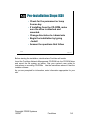
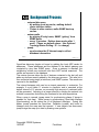
3UHLQVWDOODWLRQIWS
• The software image can be obtained from
TACtics Online or the public ftp site
• Move the ftp’d file (such as fv42_sol.tar.Z) to
one level above the intended
$FOREVIEW_HOME (such as /usr/fore or
/usr/local)
• Uncompress the file
• Once uncompressed, you can execute the tar
command
tar -xvf /usr/local/fv42.sol.tar
ForeView
10/8/97 3-6
The commands here are specific to the Solaris operating system we’ll use in the
lab. If you use a different OS, make sure you obtain the appropriate file.
The uncompress function is done with:
uncompress /usr/local/fv42_sol.tar.Z
The tar command will create subdirectories within the current location if they
don’t already exist.
A common “mistake” is to put the .tar file in
/usr/local/foreview, then extract the .tar file. The subdirectories will still be
created but the home directory will be /usr/local/foreview/foreview. This is not
fatal, just excessive. Extract with:
tar -xvf /usr/local/fv42.sol.tar
Sun Microsystems, Inc.
SunOS 5.5.5.1
sydney1# cd /usr/local
sydney1# ls
bin
fv42_sol.tar.Zsbin
fore
include
sydney1# uncompress fv42_sol.tar.Z
sydney1# ls
bin
fv42_sol.tar
fore
include
sydney1# tar -xvf /usr/local/fv42_sol.tar
Generic May 1996
man
sbin
man
Copyright FORE Systems
10/8/97
ForeView
3-6
81,;,QVWDOODWLRQ6WHSV
• Set the FOREVIEW_HOME environment
variable
/bin/csh
setenv FOREVIEW_HOME /usr/local/foreview
• After the ForeView .tar file has been
extracted, change to the /usr/local/foreview
directory and run the installation script
cd /usr/local/foreview
./foreview_ install
ForeView
10/8/97 3-7
Set the environment variable FOREVIEW_HOME to reflect the new
directories if necessary.
The extracted tar file will create the directory foreview in /usr/local. Change
directory to /usr/local/foreview:
cd /usr/local/foreview
Run the following command to begin the installation:
./foreview_ install
Answer the questions that follow to complete the installation
Copyright FORE Systems
10/8/97
ForeView
3-7
,QVWDOODWLRQ6FULSW
sydney1# foreview_install
******************************************************
****
****
****
FORE Systems ForeView 4.2 Installation
****
****
****
******************************************************
ForeView installation beginning at Fri Sep 26 16:31:34 EDT 1997.
A log of these installation steps can be found in the file:
/usr/local/foreview/tmp/fvinstall.log.
Searching for old .tcl files in the installation directories.
This distribution can run with different network management
systems: OpenView (OV), NetView for AIX (NV), SunNet Manager
(SNM), or stand-alone (SA). This program will install the
setup appropriate for the platform that you select.
It looks like you have OV installed on this machine.
Enter the management platform you are using (OV, NV, SNM, or SA) [OV]:
ForeView
10/8/97 3-8
The script will explain what is happening as well as provide choices.
Remember, it is only a script and nothing is being written to the system until
the end. You can exit the script at any time using <ctrl-c>.
Copyright FORE Systems
10/8/97
ForeView
3-8
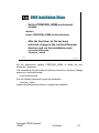
)RUH9LHZ,QVWDOODWLRQVFULSW
• Have a current temporary or permanent
license key ready
• Be familiar with the new discovery server
program and the Fvds.discSwitches
resource
• FV still creates /usr/local/foreview/conf/license
/usr/local/foreview/conf/foreview
• Be prepared to adjust the resource variables
in the configuration file
ForeView
10/8/97 3-9
ForeView checks to see if you have a license file in /tmp/fvlicense OR in
/usr/local/foreview/conf/license. If it does not find a license file, it asks you to
enter the license information.
Your ForeView product arrives with a License Certificate and a temporary
license good for approximately 90 days.
If you have no license certificate, ForeView will generate a 15-day temporary
license.
To receive a permanent license key, please fill in all the information on the
License Certificate and fax the card to FORE Systems' Technical Support.
Resource variables such as the Discovery Switch, are discussed in more
detail later.
Copyright FORE Systems
10/8/97
ForeView
3-9
&KRRVLQJDQ2SHQ9LHZ
,QVWDOODWLRQ
Installing ForeView OV platform.
Installed a template ForeView resource file as /usr/local/
foreview/conf/foreview
The ForeView discovery and status daemon needs to know the
name of a switch in the ATM
network to perform network
discovery and monitoring. This "seed" switch is stored in
your ForeView configuration file /usr/local/foreview/conf/
foreview as the resource Fvds.discSwitches. Your /usr/
local/foreview/conf/foreview file does not have this
resource defined.
We recommend that you define this resource now.
Would you like to enter this information now? [y]: y
Please enter the hostname(s) of the switch(es) (separated by
commas) that you would like to use as starting points for
the discovery process.
Fvds.discSwitches:
sydneybx
ForeView
10/8/97 3-10
The next decision you make is to install the standalone version of ForeView
or a version integrated with HP OpenView (OV), SunNet Manager (SNM), or
NetView/AIX (NV).
When an integrated version is selected, please note the standalone files are
also installed.
Copyright FORE Systems
10/8/97
ForeView
3-10
(QWHU7KH'LVFRYHU\6ZLWFKHV
Installing ForeView OV platform.
Installed a template ForeView resource file as /usr/local/
foreview/conf/foreview
The ForeView discovery and status daemon needs to know the
name of a switch in the ATM
network to perform network
discovery and monitoring. This "seed" switch is stored in
your ForeView configuration file /usr/local/foreview/conf/
foreview as the resource Fvds.discSwitches. Your /usr/
local/foreview/conf/foreview file does not have this
resource defined.
We recommend that you define this resource now.
Would you like to enter this information now? [y]: y
Please enter the hostname(s) of the switch(es) (separated by
commas) that you would like to use as starting points for
the discovery process.
Fvds.discSwitches:
sydneybx
ForeView
10/8/97 3-11
The information needed is the IP address or DNS hostname of the
ForeRunner ATM switch that will be the starting point of network discovery.
There are different strategies here. A simple strategy is to name the ATM
switch nearest you. Later, you can decide which switch or switches best suit
your application. Another strategy is to select a well-connected switch
(many NNI links) in each building or group of switches.
The IP interface specified by name or address can be ATM- or Ethernetattached, but must be reachable from this host. More on this in an
upcoming section.
Copyright FORE Systems
10/8/97
ForeView
3-11
)LQLVK7KH,QVWDOODWLRQ
Customization of OV fileset completed successfully.
Version identification created in /usr/local/foreview/conf
Building conf/fvpanel.dat file using mkfpcfg
Created conf/fvpanel.dat file using mkfpcfg successfully
******************************************************************
*** ForeView install completed on Mon Oct 6 20:07:20 EDT 1997.
***
*** All ForeView products have been enabled for a 15
*** day trial. To complete the installation, you must
*** ensure that you have a permanent license key for all
*** ForeView products you intend to use. All permanent keys
*** must be located in the file: /usr/local/foreview/conf/license
***
*** Information on obtaining and installing permanent
*** license keys can be found on your ForeView Right
*** To Use (RTU) Certificate.
******************************************************************
ForeView
10/8/97 3-12
Prior to this display, an OpenView status will have scrolled up. “RUNNING”
and “WELL BEHAVED” are the indicators you are looking for on the
OpenView processes.
When the installation is finished, ForeView will inform you of a successful
procedure
and
log
the
installation
in
the
text
file
/usr/fore/foreview/tmp/fvinstall.log. If the installation is unsuccessful, the log
will keep track of where the procedure failed.
Copyright FORE Systems
10/8/97
ForeView
3-12
)LOH6\VWHP5HVXOWV
Under the foreview directory:
• Manifest lists - complete file listing
• Directories for
• executable scripts
• applications
• housekeeping functions (MIBs, logs, etc.)
• Installation script files
ForeView
10/8/97 3-13
Manifest lists - Specific lists of all the files created as a result of the
installation. For an installation with another NMS, bothe the standalone and
integrated files will be listed. On the lab equipment, see MANIFEST-OV and
MANIFEST-SA.
Directories Executable scripts:
bin
Applications:
frontpnl
fvinv
fvmap
fvupgrad
fvcall
fvmsg
fvchan
fvoams
Housekeeping functions:
log
man*
OV
mibs
conf
fvhelp
tcl_apps tcl_lib
fvdisco
fvphub
fvgraph
fvsuppfvtracer
fvtcllib install
tmp
Installation script files - foreview_install, fvrmon_install
The script fvrmon_install is used with ForeView RMON ST, a separate
software product.
*NOTE: Support for man pages ceases with version 4.2
Copyright FORE Systems
10/8/97
ForeView
3-13
:LQ17,QVWDOODWLRQ
• Insert CD-ROM, use Explorer to
change to the \Windows directory
• To install the ForeView Stand-alone
version run setup.exe
• If you brought the file in from the ftp
site, be aware it is a self-extracting
archive. Run the .exe file to extract
the archive. Then run setup.exe.
• Remember that map labels are
derived from host names. Configure
your NT host accordingly
ForeView
10/8/97 3-14
ForeView uses NT installation tools, so it should look very familiar. To align
host names with the rest of the network, see section 2.4.2 in the user’s
manual.
If you importing the file via ftp, the file you get will be something very similar
to fv42_5nt.exe, which is a self-extracting executable. Simply run the file
and the archived files will be unpacked. Running the setup program installs
the files to their appropriate places.
Copyright FORE Systems
10/8/97
ForeView
3-14
17LQVWDOODWLRQVFUHHQ
ForeView
10/8/97 3-15
In the initial steps of the installation, ForeView will prompt for the source of
the installation files and the destination. By default the source directory is the
current directory that launched the setup.exe program and the destination is
C:\FOREVIEW.
Copyright FORE Systems
10/8/97
ForeView
3-15
17)LOHVDUHFRSLHG
ForeView
10/8/97 3-16
Copyright FORE Systems
10/8/97
ForeView
3-16
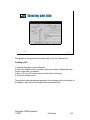
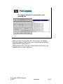
(QWHUWKHOLFHQVHLQIR
4/1/1997
bd53be67
ForeView
10/8/97 3-17
The ForeView NT installation will prompt for the IP address, products,
Expiration Date and Expiration Key Code in a dialog box. When using a
permanent license, all the fields must be completed.
The temporary license requires only the Expiration Date and the Key fields.
Do NOT fill in the fields for IP Address and Products when using the
temporary keys.
Make a special note that the format for the Expiration Date is MM/DD/YYYY
where MM is the two digit month (ie April=04), DD is the two digit date (ie 01
is the first day), and YYYY is the four digit year (ie YYYY = 1997).
Copyright FORE Systems
10/8/97
ForeView
3-17
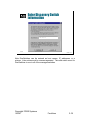
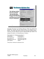
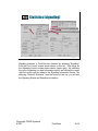
(QWHU'LVFRYHU\6ZLWFK
LQIRUPDWLRQ
198.29.21.1
ForeView
10/8/97 3-18
Note DiscSwitches can be entered as host names, IP addresses, or a
mixture. Lists entries must be comma-separated. The valid switch count for
DiscSwitches is one to all of the managed switches.
Copyright FORE Systems
10/8/97
ForeView
3-18
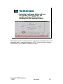
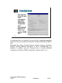
)LQLVKWKHLQVWDOODWLRQ
ForeView
10/8/97 3-19
When the installation finishes, ForeView will create a program group for
ForeView that includes icons for five different programs:
fvds
the discovery server program
fvlan
the VLAN manager program
fvmap
the ForeView topology map
fvpanel
the ForeView Front Panel device manager display
fvpsview
a tool to manage the ForeView background processes
Copyright FORE Systems
10/8/97
ForeView
3-19
8QGHUVWDQGLQJ)RUH9LHZ
0DQDJHPHQW3URFHVVHV
ForeView 4.2
10/25/97
4- 1
Copyright FORE Systems
10/25/97
ForeView
4-1
)RUH9LHZDQG1HW0JPW
6\VWHPV
• In this module we will look at:
• ForeView Discovery
• Discovery and Polling with HP OpenView
• Primary background processes
• Examine the ATM Map levels
ForeView
10/25/97
4- 2
In this module we will take our first look at the ForeView Discovery and
Status daemon. The Discovery daemon provides service to ForeView
applications in stand-alone and integrated modes.
We will look at the primary background processes and the schematic of how
Open View uses these in its operation. We can then examine the results of
the OpenView discovery and look at the default maps.
Copyright FORE Systems
10/25/97
ForeView
4-2
7KH'LVFRYHU\DQG6WDWXV
'DHPRQ
• Runs as fvdsd
• Can be local or remote to the station
running the ForeView application
• Begins discovery of the network
topology at a preset point or points
(called “Discovery Switches”)
fvdsd
ForeView
10/25/97
4- 3
ForeView utilizes a discovery and status server application that discovers
the manageable entities, that is the switches, NNI and UNI links, and the
endpoints of NNI and UNI links in the ATM network.
All switches and devices connected to any of the switches in the list, which
can be communicated with via IP and/or SNMP, will be discovered and
monitored, by default. For example take:
Fvds.discSwitches: switch1, switch2
In this case, the discovery process will discover switch1 and switch2. It will
then issue SNMP gets to find out which ports are in NNI status and the
remote IP address on that link. As get responses are returned, these
addresses are added to the list of known switches. This NNI query moves
onto the new switches, and so on, until all the switches are discovered.
The Fvds.discSwitches resource defines the switches that the daemon fvdsd
uses to begin discovery of the network, and does NOT specify what the
applications will use to show on a map.
During the installation process, if this resource is not defined in the
configuration file, the user is prompted for the Discovery Switch.
Copyright FORE Systems
10/25/97
ForeView
4-3
'LVFRYHU\6WHSV
• Once the discovery switches
(Fvds.discSwitches) are contacted, fvds asks
if they have any NNI links
• If there are NNI links, the remote address
stored for each link is retrieved
• Fvds can then make SNMP contact with
those addresses
ForeView
10/25/97
4- 4
Copyright FORE Systems
10/25/97
ForeView
4-4
7KH'LVFRYHU\6HUYHU
• After discovery, a list is generated and
subsequent status polls are sent to each
device in the list
• The “list” is a memory cache to allow for
faster discovery
• Users can customize the speed of
discovery and speed of polling through
configuration files
• When the daemon is stopped, the cache
is dumped
ForeView
10/25/97
4- 5
The fvds daemon has two tasks. First, the application discovers the network
elements and polls the information to keep its own internal cache up-to-date.
Second, it makes the network topology and status information available to
clients through a TCP socket. Remote ForeView stations can contact these
fvds instances and read data from there.
It is important to note that the Discovery Server will not “volunteer” or
“relinquish” the data without an appropriate request from one of these
applications.
Fvdsd is a true server and does not send things out unsolicited. Therefore,
when a client asks for status on a particular object such as port 1b3 on a
switch named Voyager, it will respond. This is why the interval value for
fvovmon is important, it asks fvdsd if any switch status has changed
according to the interval. A switch may have actually changed status 10
minutes ago, but until fvovmon asks for the information, it will not make the
appropriate changes. So, when configuring fvovmon and fvdsd, their pollings
should be configured with this in mind.
Copyright FORE Systems
10/25/97
ForeView
4-5
$FWLYLW\RIIYGVG
• Many different OIDs are collected from the
switch
• This data is given to the mapping utility for
interpretation
• Standalone uses fvmap
• Integrated (OV) uses fvovmon and
fvovmap
ForeView
10/25/97
Status, general switch info:
4- 6
Multiple interfaces on a switch:
switchAtmAddress
variables in ifTable
switchType
variables in ipAddrTable
envMgmtBoardSerialNumber
switchThisAgentBoardNumber
Port/link discovery and status info:
controlPort
hwPortOperStatus
sysObjectId
portOperStatus
portRemoteIpAddress
Netmod info:
portRemoteAtmAddress
hwPortNumber
portNumber
hwPortGlobalIndex
portManagementStatus
moduleNumber
moduleBoard
moduleNumberOfPorts
Sigpath (SPANS and UNI) discovery and status info:
sigPathPort
sigPathRemoteAtmAddress
sigPathVPI
q2931AdminPort
sigPathVCI
q2931AdminVPI
sigPathOperStatus
q2931AdminVCI
sigPathRemoteIpAddress
q2931OperStatus
portOperStatus
q2931AdminRemoteIpAddress
portRemoteIpAddress
q2931AdminOPerType
portRemoteAtmAddress
q2931UNIOperVersion
portNumber
q2931PeerPort
Copyright FORE Systems
10/25/97
ForeView
4-6
'LVFRYHUHG2EMHFWV
• Links and switches are separate
objects and polling can be controlled
separately for each object. All this
info is kept in the fvdsd
cache/database until needed.
• The user doesn’t see the contents of
fvdsd. The objects displayed are a
represention of what the application
(fvovmap, fvmap, fvovmon, etc.) last
received from fvdsd.
ForeView
10/25/97
4- 7
Discovery server is initially slow to discover the networks but eventually
caches all switches found in memory for later use. If it found 70 switches, it
would put each one in the cache as individual objects for use later by the
topology .
If you start up fvmap right away, it will act as a client to fvdsd, asking what it
knows. It may have only discovered one switch, so only one switch will be
displayed. As fvdsd learns more and more, fvmap continues to ask about
the network. Only after full discovery can fvmap get all the information it
needs to map the whole network.
To prevent the “partial map” problem, fvdsd should be started first, then after
time passes (about an hour with defaults), start map or other client functions.
Copyright FORE Systems
10/25/97
ForeView
4-7
8QGHUVWDQGLQJ
)RUH9LHZ2SHQ9LHZ
0DQDJHPHQW3URFHVVHV
ForeView 4.2
10/25/97
4- 8
Copyright FORE Systems
10/25/97
ForeView
4-8
2SHQ9LHZ3URFHVVHV
• The primary processes that are used by
OpenView are based on three steps
• Discovery - ovtopmd works to find
the unknown
• Polling - netmon keeps up-to-date on
known devices
• Mapping - ipmap graphically
interprets the information
ForeView
10/25/97
4- 9
HP OpenView is one the more popular ways of managing an IP network. It
uses SNMP to gather information about devices with IP addresses without
discriminating about whether they are connected by Ethernet, Token Ring,
FDDI, or ATM.
OV runs as a collection of persistent processes that are started when the
host workstation boots up. These processes include System Process
Management Daemon (ovspmd), an SNMP data collector (snmpCollect), a
trap management daemon (ovtrapd), an action/reaction daemon
(ovactiond), the database of devices (ovwdb), a topology manager
(ovtopmd), and a polling daemon (netmon). All of these processes run in
the background when OpenView is started. When requested by the
application, a mapping daemon (ipmap) will take information from the
database to make the topology map and adjusts the map based on traps
and polling.
The operation of netmon and ipmap is independent of any ForeView
processes.
Copyright FORE Systems
10/25/97
ForeView
4-9
%DFNJURXQG3URFHVV
ovtopmd discovers
• by walking local arp cache; walking default
router interface tables
• Chains to other routers; walks SNMP host arp
caches
• netmon polls
• by pinging IP-only hosts; SNMP “getting” from
SNMP hosts
• every 15 minutes. Deletes down nodes after 1
week. (These are default values - Use Options /
Topology/Status Polling: IP... to change)
• ipmap
• synchronizes the IP Internet map to reflect
database information
•
ForeView
10/25/97
4- 10
OpenView discovery begins at home by walking the local ARP cache for
addresses. These addresses and the address of the default gateway are
contacted by ping then SNMP query. Once a gateway is reached, the
neighboring routers are contacted, and their ARP caches examined. The
results are reported to the database.
The netmon process takes the list of devices contacted in the last poll and
adds any devices recently added by the discovery process. This new list is
then contacted using pings (at minimum) and SNMP queries. The results are
reported to the database.
The interval between polls can be an import parameter to customize. For
example, if a poll takes 11 minutes to complete, and is executed at the
default interval of 15 minutes, an unusually high amount of overhead traffic
will be generated. Adjusting to a longer interval or dividing the network into
multiple communities could bring the overhead in line with expectations.
When a map is opened, ipmap starts it’s synchronizing phase (if ipmap is
enabled for that map). While ipmap is synchronizing, OpenView displays
[Synchronizing] on the status bar of all displayed submaps. During this
phase, ipmap searches the OpenView Database (ovwdb), and looks for
changes since the map was last opened. If new objects are discovered,
ipmap brings the map up to date by drawing new symbols.
Copyright FORE Systems
10/25/97
ForeView
4-10
+32SHQ9LHZ)ORZFKDUW
Discovery
Mapping
(traps)
ipmap
ovtopmd
2
1
(traps)
5
paris1-tftpboot> gifconfig -a
A. GINIMs have a maximum throughput
B. Packet Engine-1 With a Packet
90,000 pps bridging through PE
60,000 pps routing through PE
The information in A and B must be
paris1 #
paris1 #
paris1 #
paris1
Network
4
3
ovwdb
netmon
ForeView
Polling
10/25/97
4- 11
1
ovtopmd discovers the network topology
2
ovtopmd builds a database (ovwdb) that is stored on the host
3
netmon then checks the network devices against the database to
find any inconsistencies
4
netmon continues to poll and adjust the database for all changes.
5
ipmap renders the information graphically, receiving input from
ovwdb and real-time traps from ovtopmd and netmon
Copyright FORE Systems
10/25/97
ForeView
4-11
)RUH9LHZ293URFHVVHV
• ForeView collects information separately
from OpenView and adds three processes to
achieve an ATM map
• ForeView polling - fvovmon
• ForeView trapping - fvovtrapd
• ForeView mapping - fvovmap
ForeView
10/25/97
4- 12
ForeView is responsible for maintaining and displaying information about the
FORE Systems portion of the network. ForeView uses many of the
OpenView APIs so the look of the information is familiar to an OpenView
user.
In addition to displaying and tracking the status of FORE devices, a separate
map must be kept for the ATM topology. The ipmap OpenView displays is
subnet-centric communicating reachability. ForeView’s map is switch-centric
and communicates connectivity. This is a reflection of the difference in
nature between a connectionless (traditional IP) network and connectionoriented (ATM) network.
The processes needed are fvovmon for polling, fvovtrapd to process traps
and fvovmap to integrate ATM information into the OpenView database. All
three are clients of discovery server instances in the network.
In release 4.2 and earlier, the fvovmon process polls devices for status using
information from both the fvdsd cache and the OpenView database (items
identified as FORE devices). Therefore, the IP identity of a switch
discovered by ovtopmd could seed fvdsd with a starting point for discovery.
For releases later than 4.2, scalabilty and performance are improved, as no
interaction between discovery processes takes place.
Copyright FORE Systems
10/25/97
ForeView
4-12
)RUH9LHZZLWK2SHQ9LHZ
Mapping
Discovery & Polling
fvdsd
(traps)
fvovmap
fvovmon
paris1-tftpboot> gifconfig -a
A. GINIMs have a maximum throughput
B. Packet Engine-1 With a Packet
90,000 pps bridging through PE
60,000 pps routing through PE
The information in A and B must be
paris1 #
paris1 #
paris1 #
paris1
ovwdb
netmon
ipmap
ForeView
10/25/97
4- 13
ForeView installation adds some persistent processes that accompany the
OpenView processes - the ForeView discovery server (fvds) a ForeView
trapping daemon (fvovtrapd) and the ForeView polling daemon (fvovmon).
The fvovtrapd daemon receives traps from OpenView’s trapd process and
then relays the information to a non-persistent mapping application called
fvovmap.
The fvovmon daemon is responsible for inserting any changes on FORE
items into the OpenView database ovwdb, usually after some trap has been
received and forwarded. The database starts by getting its initial device
information from all the IP items and brings back their IP addresses, device
specifics, etc through SNMP. It then evaluates the ATM devices and
extracts them to the Discovery Server database of cached objects.
The Discovery server database can be filled in manually if the user wishes to
“jump start” the discovery process. Host names can be added to the
ForeView configuration file - for example cat.fore.com, python.fore.com. The
fvovmon process then queries the database regularly, updates it, and
passes information along to fvovmap. The fvovmap daemon runs only when
the ATM map is active and is not a persistent process like the other two. Its
function is to control the ATM map and to make changes when notified
through polling or trap mechanisms.
Copyright FORE Systems
10/25/97
ForeView
4-13
6WDWXV3ROOLQJ
• After fvovmon discovers a ForeRunner
ATM switch, it polls it regularly to check
for status, topology, and configuration
changes.
• At the end of the polling cycle, a new
polling list is developed for the next
polling cycle.
• Under OpenView, a switch is declared
“dead” if fvovmon fails to get a response
for four cycles in a row.
ForeView
10/25/97
4- 14
After fvds discovers a ForeRunner ATM switch, it polls it regularly with fvovmon
to check for status, topology, and configuration changes. It creates a polling list
and then polls regularly to get info from the standard switch MIB on cells
transmitted, link status, etc. fvovmon uses SNMP to accomplish this information
polling and may bring back an ATM switch’s ATM address and other
parameters
from
FORE-specific
switch
MIBs
as
well.
After the switch, network module, and port and signaling info is retrieved, it is
parsed and the object database is updated. If an interswitch connection is
discovered, the remotely connected switch is added to the polling list. After all
switches in the polling list are polled, an updated list of polled switches is written
to a file. This file serves as the seed file for the next polling cycle.
When a new polling cycle starts the seed file is read. At that time, the OpenView
database is searched for new switches may have been discovered by
netmon/ipmap. The switches in the polling list are polled, and both the database
and polling list are updated accordingly.
A switch is declared “dead” if fvovmon fails to get a response for “n” polling
cycles in a row. The current default value for “n” is 4. Every 15 minutes,
fvovmon checks the database of all managed objects. If an object has not been
updated for 24 hours the object becomes unmanaged and fvovmap is notified.
Copyright FORE Systems
10/25/97
ForeView
4-14
2SHQ9LHZ6WDUWXSDQG6KXW
GRZQ
• Use ovstart to start up OpenView and
ForeView background processes
• Use ovstatus to list status of OpenView
and ForeView background processes
• Use ovstop to stop OpenView and
ForeView background processes
• OpenView and ForeView background
processes are automatically started on
system boot-up
ForeView
10/25/97
4- 15
OpenView and ForeView both run in the background, meaning they are
operating even when the user is not currently using the applications.
Using the ovstart command causes both the OpenView and ForeView
processes to begin running. The ovstatus command will show a list of all the
background processes and their status. The ovstop command will stop all
the background processes. These commands can be used globally (without
specifying any options or particular processes), or as directed commands to
individual processes.
ovstart, ovstop, and ovstatus can all be used to start, stop, or get status on a
single OpenView background process
ovstart fvds (starts the discovery server)
ovstart fvovmon (starts fvovmon)
ovstatus snmpCollect (status on snmpCollect)
ovstop (stops all OpenView and ForeView background processes)
Copyright FORE Systems
10/25/97
ForeView
4-15
+DQGOLQJ7UDSV
• fvovtrapd can request information from
fvdsd when trying to process traps.
• All traps are verified before they are sent
on to be processed by OpenView
fvovtrapd
1c3
discovery
request
ovtrapd
Alpha
fvdsd
status
request
original trap message
ForeView
10/25/97
4- 16
Conceptually, when fvovtrapd receives a trap, it filters the trap to be sure it’s
from a FORE Switch, then decodes the message. Then fvdsd is requested
to verify the trap information.
For example, the trap indicating a link failure on port 1c3 of a switch named
“Alpha” (wide arrow) would trigger fvovtrapd to request fvdsd to discover the
status of Alpha:1c3 (black lines).
Fvdsd sends an SNMP Get Request to Alpha querying that port (black lines
to Alpha). If a change has taken place, fvdsd’s cache is updated. When
fvdsd receives Alpha’s response, a message goes to fvovtrapd indicateing a
response has been received. Now fvovtrapd can request the status of
Alpha:1c3 from fvdsd (dashed lines).
This verifies the contents of the trap using discovery and status processes in
fvdsd. This process is used to verify all FORE SNMP traps. If the
verification shows the trap to be incorrect, then fvovtrapd will not update
anything in the OpenView database, nor will it update fvovmap. If
something has changed, fvovtrapd will notify the database and the ATM
map.
Copyright FORE Systems
10/25/97
ForeView
4-16
0DSSLQJ
ForeView 4.2
10/25/97
4- 17
Copyright FORE Systems
10/25/97
ForeView
4-17
0DSSLQJ%DVLFV
• Network is displayed as switches and NNI
links
• Submaps can be launched by doubleclicking
• Switch objects can be re-arranged with
right button of a two-button mouse or the
middle button of a three-button mouse
ForeView
10/25/97
4- 18
The connectivity-based map displays switches and links at the top level,
adding more detail in submaps.
The objects on any standalone map can be moved around to suit your
tastes by using the proper mouse buttons. On the Integrated maps, the
display must be a read/write access map to re-arrange things.
In OpenView, the first map opened gets read/write privledges, additional
instances are read-only.
Copyright FORE Systems
10/25/97
ForeView
4-18
2SHQ9LHZ6WDWXV&RORUV
Unknown
(dark blue)
Unknown
Unmanaged
(tan)
Not polled
Normal
(link=black,symbol=green)
Operational
Warning
(cyan)
One underlying object is red
Minor/Marginal
(yellow)
More than one underlying object is red
Major
(orange)
All but one underlying object is red
Critical
(red)
Down
ForeView
10/25/97
4- 19
Objects are colored according to their status. If an object is made of subcomponents, the status of the sub-components affects the higher level
status.
Also, events can have a color set, according to their severity.
The default severity settings are:
*Critical *Major *Minor *Warning *Normal -
Network Mgmt System going down
Router, subnet going down
Switch/host going down
Alerts user of changes
Host up/down
Copyright FORE Systems
10/25/97
ForeView
4-19
2SHQ9LHZ0DS/HYHOV
OpenView Internet map has four levels:
• Root - contains the main icon for IP
Internet
• IP Internet - Subnets, routers, and
multi-homed hosts
• Network- Segments, routers and
multi-homed hosts
• Segment- All nodes show up in
Segment map
ForeView
10/25/97
4- 20
OpenView will initially present the Root map showing two icons - one for the
IP internet and the other for the ATM network (installed by ForeView).
When you double-click on an icon, you “explode” the icon into the next
submap layer. On the IP map side, if you explode through each level and
then explode a host from the Segment map, you will see the host interfaces
including fa0 (ATM interface ), qaa0 through qaa3 (Classical IP interfaces),
le0 (for Ethernet port), and el0-16 (for defined VLANs).
On the ATM map side, ForeView concentrates on showing all the switches
and their interswitch and host connections. ForeView shows the host and
switch devices as well as detailed information on the signaling paths used to
communicate with them.
When communicating with a device that is comprised of other devices such
as an ASX1000, ForeView will show the enclosure and its component
fabrics. ForeView will show an icon for the ASX1000 with a label of
“Enclosure”. When the enclosure is double-clicked, a submap with each
icons for each individual fabric is shown. Double-clicking on a fabric is like
selecting a stand-alone BX switch.
Copyright FORE Systems
10/25/97
ForeView
4-20
5RRW0DS
ForeView
10/25/97
4- 21
Under OpenView, all ForeView functions are found under the ForeView
menu.
Copyright FORE Systems
10/25/97
ForeView
4-21
,3,QWHUQHW
2
1
ForeView
10/25/97
4- 22
This is the result of ipmap. Its subnet-centric view displays each subnet plus
any special devices in the subnet (gateways, etc.).
1. The subnet icon, the color indicates it is up.
2. One special device is a ForeRunner ATM switch, note its icon.
Copyright FORE Systems
10/25/97
ForeView
4-22
)RUH9LHZ6WDWXV&RORUV
• ForeView maps all network elements in
three colors
• Green - Element is fully reachable and
signaling is up
• Yellow - This element is of marginal status.
Perhaps signaling is down.
• Red - Element cannot be reached. Carrier
is down
ForeView
10/25/97
4- 23
ForeView uses universally accepted colors to represent the status of an
object in the map.
For example, when a host symbol becomes red, that means that the host
cannot be reached (pinged) from the management station. The status of a
link is based on the combined status of the signaling paths that make up that
link. A black link means that it is operational. A link of any other color
indicates that one or more signaling paths on that link is down.
If the color of a switch turns red, it indicates either:
•an unsuccessful poll of the switch for some period of time
•a trap indicating a down state was verified
Copyright FORE Systems
10/25/97
ForeView
4-23
)RUH9LHZ2SHQ9LHZ0DSV
ForeView-OV ATM Networks has five map
levels
• Root - contains the main icon for ATM Networks
• ATM Networks - all switches and interswitch
connections that exist in the managed network
• ATM Switch Connections - switch in star topology
• ATM Links - all unidirectional links between
switches
• Signaling Paths Submap/Fabrics Submap - detail
of links showing UNI and SPANS data/detail of
ASX1000 enclosure showing individual fabrics
ForeView
10/25/97
4- 24
Copyright FORE Systems
10/25/97
ForeView
4-24
$701HWZRUNV
ForeView
10/25/97
4- 25
Copyright FORE Systems
10/25/97
ForeView
4-25
$706ZLWFK&RQQHFWLRQV
1
4
2
3
ForeView
10/25/97
4- 26
The Switch Connections map shows all the devices attached to a particular
switch.
1. Name labels are used when the interface’s name is known
2. IP address labels are used if names are not known
3. The icon shows what kind of device is attached
4. The port number of each link is displayed, referencing the switch at the
center.
Copyright FORE Systems
10/25/97
ForeView
4-26
+329DQG1HW9LHZ2QO\
• Link status submap including hardware
carrier status
• Link propagation to higher levels
• When a switch fails, the network icons on
higher map will now reflect a status change by
changing colors.
ForeView
10/25/97
4- 27
Since a link is a separate, managed object, three different characteristics
can be displayed in a submap.
Hardware carrier - If carrier is down, signaling will also be down
NOTE: Following release 4.2, this object will be called “Line Status” and will
incorporate carrier and physical link status (such as alarms)
SPANS - If green, SPANS communication between the devices is running
error-free
UNI - if green, UNI messages are being exchanged
Copyright FORE Systems
10/25/97
ForeView
4-27
0HWD&RQQHFWLRQV
ForeView
10/25/97
4- 28
A logical link between two switches may be made of more than one physical
link. Meta connections indicate port numbers at each end.
Copyright FORE Systems
10/25/97
ForeView
4-28
3UDFWLFH/DE0DSOHYHOV
• Objective - In this lab, you will be
given some time to explode the maps
in the IP Internetwork icon and also
the ATM Networks icon to find the
symbols within.
ForeView
10/25/97
4- 29
Procedures
1. From the OpenView Root Map, double-click the IP Networks icon.
2. From the OpenView Root Map, double-click the ATM Networks icon
3. Examine the way the IP map lays out each network with a label and how it
shows ATM devices (switches, hosts, etc.)
4. Examine the way the ATM maps lay out the network and shows the relationship
of switches and hosts.
5. Double-click on links on either map to see what happens. Notice the labeling
conventions that are used to identify the links and ports. Can you explode a link
from a switch to a host (UNI)? How about switch to switch (NNI)?
6. Try to answer the following questions:
What interfaces does your host have? ____________________
How many interfaces on a switch? ____________________
What are the differences between the IP map and the ATM map?
______________________________________________
___________________________________________________
___________________________________________________
Copyright FORE Systems
10/25/97
ForeView
4-29
/DE5HVXOWV
IP Internet Submap
IP Network Submap
ForeView
10/25/97
4- 30
After double-clicking on the Root Map icon for IP Internet, you should see
the IP Internet submap appear. Note how OpenView assigns separate
symbols for IP network addresses (for example you may have a round icon
with a triangle in it with a network id of 198.29.21.0). The map also shows
symbols for routers and switches and uses colors to give their status.
Copyright FORE Systems
10/25/97
ForeView
4-30
/DE5HVXOWVFRQW·G
ATM Network Submap
Switch Connections Submap
ForeView
10/25/97
4- 31
ForeView shows the ATM network as a series of linked switches and allows
the user to then “explode” the switches to show connected hosts, edge
devices, and NNI connected switches.
Each link is labeled with the connection port on the switch. Interswitch links
are labeled with a source and destination port. When there are redundant
links between switches, OpenView returns a “metalink” - a single line with no
label.
When you double click on a metalink, it will explode into its component
unidirectional links. For example, if there are two links between switches
and you double click on the metalink, OpenView will explode the link into
four individual links - unidirectional sends and receives on one link and then
the send and receive on the other link.
Copyright FORE Systems
10/25/97
ForeView
4-31
3UDFWLFH/DE)RUH9LHZ·V$70PDS
• Objective - Examine the mapping of
ATM devices found via the OpenView
map. Open the alternate map to
compare the Stand-alone version to
the OpenView version.
ForeView
10/25/97
4- 32
Procedures:
1. From the OpenView “Root” map, double-click on the ATM Networks icon
to bring up the ATM Networks submap. Examine the “star topology” layout of
the map and how switches are linked.
2. From the OpenView menu line bring up the ForeView menu options.
Choose “Alternate Map” and watch as ForeView maps using the Standalone module (even running concurrently with the OpenView map)
3. Close the alternate map by choosing File/Exit from the map’s menu line.
Copyright FORE Systems
10/25/97
ForeView
4-32
)RUH9LHZ
&RQILJXUDWLRQ
ForeView
10/14/97
5-1
Copyright FORE Systems
10/14/97
ForeView
5-1
3URGXFW/LFHQVLQJ
• Software licensing provides an on/off
switch for multiple products
• Temporary license turns all products on
• Permanent licenses activate software
product-by-product
• All licenses contained in /tmp/fvlicense
or $FOREVIEW_HOME/conf/license
ForeView
10/14/97
5-2
The various ForeView applications check for the presence of a valid key on the
host. Generally speaking, users migrate a station from a temporary license to a
permanent license tied to the IP address of the host.
With Foreview 4.2, FORE’s TAC generates a license key by serial number and
IP address. Each product a customer buys has its own serial number. A
license key is generated for each one and then 'stacked' into the ForeView
license file.
For example, if the NMS IP address is
0000111111, we would get:
1.1.1.1
and the serial number is
# ForeView License Certificate
Address:
1.1.1.1
Products: FV
Key:
26715c72
Also, a customer can lump these keys together for administrative ease. If he
had puchased 5 copies of ForeView for 5 stations, one file containing all 5
licenses could be copied to all machines instead of making sure each license file
had the correct key on each machine.
Copyright FORE Systems
10/14/97
ForeView
5-2
)RUH9LHZ$SSOLFDWLRQV
• Collectively comprise ForeView
• Can be started from a command line
• Unqualified entries consult the
configuration file or accept defaults
• Settings in the configuration file can be
overridden by command line syntax
• Most can be started from the GUI
• This will always consult the configuration
file or accept defaults
ForeView
10/14/97
5-3
Directories of ForeView applications:
frontpnl -
Front panel element management tools
fvcall -
Call record/statistics tools
fvchan -
Virtual path/virtual channel tools
fvdisco -
Discovery and status server diagnostic utility
fvgraph -
Graphing and logging tool
fvhelp -
Help files
fvinv -
Network inventory tool
fvmap -
ATM mapping tools
fvoams -
OA&M cell activation and monitoring
fvphub -
Element management of PowerHub products
fvtaclnk -
Error and stack trace utility
fvtracer -
Channel tracing tool
fvswmgr -
Software management/upgrade tool
Copyright FORE Systems
10/14/97
ForeView
5-3
)RUH9LHZ&RQILJXUDWLRQ)LOH
• A simple ASCII file containing optional
and required resources.
• None of the resources are active initially,
but most are pre-set with factory default
settings
• Read each time a particular application
is started
• The most concise description of
configuration choices
ForeView
10/14/97
5-4
General format:
ResourceName: value [, value] [, value] ...
or
Specifier.ResourceName: value [, value] [, value]
Samples:
ClusterName.123: CentralASX1000
In this case, ClusterName has only one value, no other information is
needed.
Fvds.discSwitches: romebx, 1000-5
Here, the specifier, Fvds, is given multiple values, which are names or IP
addresses of switches to use for discovery starting points.
Copyright FORE Systems
10/14/97
ForeView
5-4
&RPPDQG/LQH([HFXWLRQ
• Applications can be accessed quickly
• Syntax contains options allowing fast
customization
ForeView
10/14/97
5-5
The recommended method of configuration is to store desired values in the
configuration file. However, certain circumstances make command line
execution appropriate because different resource values can be specified in
the command line, overiding the parameters in the configuration file.
For example, if a network failure occurred, and it would be helpful for
troubleshooting to more frequently poll certain switches, the regular fvdsd
instance could be stopped and a new instance with very different behavior
could be started. This would provide more up-to-the-minute information
about the equipment in question.
# more /usr/local/foreview/tmp/DS.pid
# kill -9 <contents-of-DS.pid>
# fvds -t -pollNNIDevices 20 -pollNNILinks 1 -discInterval 2 -discSwitches cannes,
marseille, paris -discInListOnly
This fvdsd instance would limit its discovery and status polling to a few
switches and provide information 5 times faster than the regular parameters
would and would write all the results to a log file.
Parameter
Normal value “New” value
time between switch polls
30 sec.
20 sec.
time between NNI link polls
3 min.
1 min.
time between discovery polls
15 min.
2 min.
switches polled
entire network
3 switches
Copyright FORE Systems
10/14/97
ForeView
5-5
)YGV&RQILJXUDWLRQ
• Discovery options: what’s new in the
network?
• Polling options: how are things in the
network?
discovery
fvds
status
ForeView
10/14/97
5-6
Copyright FORE Systems
10/14/97
ForeView
5-6
)YGV2SWLRQV'LVFRYHU
:KDW"
• Fvds.discSwitches- required
• Fvds.locations- for remote fvds
• Fvds.discInterval- time between
discoveries
• Fvds.discNoUNIs- do not discover
UNI links
• Fvds.discNoUNIDevices- do not
discover end devices
• Fvds.discInListOnly- only discover
switches in discSwitches
ForeView
10/14/97
5-7
Fvds.discSwitches: defines a list of Fore ATM switches to be used by the discovery and
status daemon as starting points for network discovery. All switches and devices connected
to any of the switches in the list, which can be communicated with via IP and/or SNMP, will
be discovered and monitored, by default. Note that this resource defines the switches that
the daemon fvdsd uses to discover the rest of the network, and does NOT specify what the
applications will use to show on a map. Applications that retrieve this resource: fvdsd. No
default.
Fvds.locations: defines the DNS names of the hosts on which the discovery and status (fvds)
daemons are running. Applications that need to retrieve information from the daemons use
this resource to determine where the daemons are running. In general, if this resource is not
defined, or the fvds daemon on the specified host cannot be reached, applications attempt to
contact a daemon on the local host. Applications that retrieve this resource: fvinv, fvmap,
fvupgrad, fvovmon, and fvovtrapd. Example: Fvds.locations: london1:7890, 10.5.25.4:7891.
No default.
Fvds.discInterval: interpreted in minutes, this resource specifies the interval over which all
known switches, their links, and connected hosts are "discovered" -- i.e., all information about
these devices are retrieved from the switches/hosts. Application that retrieves this resource:
fvdsd. Default: 15
Fvds.discNoUNIs: this resource takes a boolean value. When set to TRUE, no UNI devices
or links are discovered by fvdsd. Application that retrieves this resource: fvdsd. Default:
FALSE
Fvds.discNoUNIDevices: this resource takes a boolean value. When set to TRUE, no UNI
devices are discovered by fvdsd. I.e., the link information to the UNI devices is discovered
and monitored, but information about the endpoint is not discovered or monitored. Application
that retrieves this resource: fvdsd. Default: FALSE.
Fvds.discInListOnly: this resource takes a boolean value. When set to TRUE, no NNI
devices besides those explicitly listed in the discSwitches argument/resource are discovered
or polled. Application that retrieves this resource: fvdsd. Default: FALSE.
Copyright FORE Systems
10/14/97
ForeView
5-7
)YGV3ROOLQJ2SWLRQV
+RZ)UHVK,V)YGV·'DWD"
Polling intervals by object type:
• Fvds.pollNNIDevices
• Fvds.pollNNILinks
• Fvds.pollUNIDevices
• Fvds.pollUNILinks
• Fvds.removeInterval- when to pull
an object from the polling list
ForeView
fvds
10/14/97
5-8
Fvds.pollNNIDevices: interpreted in seconds, this resource specifies the interval
for polling all known switches for their statuses. Application that retrieves this
resource: fvdsd. Default: 30. Note: After release 4.2, this resouce will be in
minutes, default: 1.
Fvds.pollNNILinks: interpreted in minutes, this resource specifies the interval for
polling all known NNI links for their statuses. Application that retrieves this
resource: fvdsd.
Default: 3.
Fvds.pollUNIDevices: interpreted in minutes, this resource specifies the interval
for polling all known UNI devices for their statuses. Application that retrieves this
resource: fvdsd. Default: 10.
Fvds.pollUNILinks: interpreted in minutes, this resource specifies the interval for
polling all known links to UNI devices for their statuses. Application that
retrieves this resource: fvdsd. Default: 30.
Fvds.removeInterval: interpreted in minutes, this resource specifies the time that
a switch must be recorded as down before its status is changed to "removed".
Application that retrieves this resource: fvdsd. Default: 60.
Copyright FORE Systems
10/14/97
ForeView
5-8
&XVWRP3ROOLQJ/LVWV
If current options don’t suffice, separate
lists can be defined:
• Fvds.IPList- devices to be contacted
• Fvds.pollIPInterval- how often polled
• Fvds.discIPInterval- how often new
objects are discovered
ForeView
10/14/97
5-9
Fvds.IPList[0-20]: this resource takes a comma-separated list of IP addresses
or hostnames as its value. The list number 0-20 identifies these hosts as
belonging to a special group of devices that should be discovered and/or polled
by fvdsd at a different rate than the other devices.
Fvds.pollIPInterval[0-20]: interpreted in minutes, this resource specifies the
interval that the devices in a list should be polled for their statues.
Fvds.discIPInterval[0-20]: interpreted in minutes, this resource specifies the
interval that the devices in a list should be discovered. "Discovery" of a device
means that the fvdsd retrieves all the information about the device that it can.
Example:
Fvds.IPList1: paris1, romebx, 10.4.4.2, paris-3810
Fvds.pollIPInterval1: 10
Fvds.discIPInterval1: 15
Fvds.IPList2: london1, 1000-5
Fvds.pollIPInterval2: 6
Fvds.discIPInterval2: 11
Copyright FORE Systems
10/14/97
ForeView
5-9
'LVFRYHU\3UREOHP
• To which of many interfaces does the
NMS have connectivity?
SPANS
I have an NNI to 10.2.2.1
and another NNI to 12.3.4.5
UNI
asx0 10.2.2.1
el20 12.3.4.5
asx0 10.2.2.3
ie0
5.5.5.30
el20 12.3.4.8
NMS
5.5.5.1
ForeView
?
10/14/97
5-10
Copyright FORE Systems
10/14/97
ForeView
5-10
3UHIHUHQFH,WHPV
A selection algorithm can be controlled
by defining these resources:
• PreferSigType
• PreferSigVPI
• PreferRemoteIPAddrs
ForeView
10/14/97
5-11
Because a devce in the network is discovered with signaling information and
its reported IP address, multiple sets of this information can cause confusion.
These resources help influence an algorithm used to determine which among
several sets of information will be used by ForeView.
PreferSigType: this resource takes one of "SPANS", "UNI30", or "UNI31" as a
recognized value. This resource specifies how host information should be
shown when there are multiple signalling paths from a switch to the host. No
default.
PreferSigVPI: this resource takes an integer as a value. This resource
specifies how host information should be shown when there are multiple
signalling paths from a switch to the host. No default.
PreferRemoteIPAddrs: this resource takes a comma-separated list of IP
addresses or IP ranges. A range is specified using either "*" to mean all
value subcomponents (1-255), or "x-y" to mean all integers between x and y
inclusive. For example:
PreferRemoteIPAddrs: 169.143.243.7-250, 10.11.*.14, 122.234.33.11
Copyright FORE Systems
10/14/97
ForeView
5-11
)YPDS&RQILJXUDWLRQ
+RZ$FFXUDWH,V)YPDS"
• Fvmap.pollInterval
• Fvmap.pollFrequency
• ClusterName
fvds
ForeView
10/14/97
5-12
Fvmap.pollInterval: this resource specifies the polling interval for the standalone
map in seconds. The standalone map polls the discovery server in every
'Fvmap.pollInterval' seconds to update the statuses of switches and links
displayed on the map. Used by fvmap. Defaults to 600 (10 minutes).
Fvmap.pollFrequency: this resource specifies the frequency with which fvmap
asks discovery server for newly discovered switches in addition to status. This
resource defaults to 5, therefore, fvmap will query for new switches on every
6th polling cycle.
An example at default settings:
12:00 - Initial discovery complete
12:10 - 1st poll
12:40 - 4th poll
12:20 - 2nd poll
12:50 - 5th poll
12:30 - 3rd poll
1:00 - 6th poll discover new objects
ClusterName.<enc_id>: defines a mapping between a cluster's (ASX-1000)
enclosure identifier and a more human-readable name. In addition to its effect
on ForeView maps, this resource is read by OpenView, NetView and SunNet
Manager mapping utilities. No default.
Copyright FORE Systems
10/14/97
ForeView
5-12
)YRYPRQ&RQILJXUDWLRQ
+RZ$FFXUDWH,V29:'%"
• Fvovmon.PollNetInterval
• Fvovmon.PollDBInterval
• Fvovmon.PollSwitchStatusInterval
• Fvovmon.PollHostStatusInterval
• Fvovmon.PollLinkStatusInterval
• Fvovmon.RemoveInterval
ForeView
10/14/97
5-13
Fvovmon.PollNetInterval: specifies the amount of time between subsequent
polls of all switches in the network. Analogous to a discovery cycle.
Default is 900 (15 minutes).
Fvovmon.PollDBInterval: specifies the amount of time between subsequent
polls of the OVw database. Default is 3600 (60 minutes).
Fvovmon.PollSwitchStatusInterval: specifies the amount of time in seconds
between subsequent queries to the discovery and status daemon for
changes in the status of managed switches. Analogous to a status poll.
Default is 30.
Fvovmon.PollHostStatusInterval: specifies the amount of time in seconds
between subsequent queries to Fvds for changes in the status of managed
UNI devices. Default is 600 (10 minutes).
Fvovmon.PollLinkStatusInterval: specifies the amount of time in seconds
between subsequent queries to Fvds for changes in the status of managed
links. Default is 300 (5 minutes).
Fvovmon.RemoveInterval: the amount of time in seconds an object in the
OVwdb is "dead" before it is removed from the map. Default is 86400 (7
days).
Copyright FORE Systems
10/14/97
ForeView
5-13
/LQNLQJ:LWK2SHQ9LHZ
SNMP config:
• copy OV’s SNMP configuration file to
FvsnmpConfFile resource
• create a custom fvsnmp.conf
• If discovery daemon is not on this host,
remove it from OV startup:
• ovstop -v
• ovdelobj /etc/opt/OV/share/lrf/fvds.lrf
ForeView
10/14/97
5-14
If ForeView is added to an existing NMS, it is simple to align ForeView’s
SNMP configuration to the existing OpenView configuration. ForeView
reads the OpenView format, so it is only a question of getting the information
in place.
For
example,
assume
the
source
of
the
information
is
/usr/OV/conf/ovsnmp.conf. You can modify the FvsnmpConfFile resource in
the $FOREVIEW_HOME/conf/foreview file to read:
FvsnmpConfFile: /usr/OV/conf/ovsnmp.conf
Users of OpenView 4.0 on Solaris or HP-UX 10.x should use:
FvsnmpConfFile: /etc/opt/
You can make a custom configuration file or copy the ovsnmp.conf file to
$FOREVIEW_HOME/conf/fvsnmp.conf.
This is especially helpful when the community strings are not “public” and
“private” and where multiple communities will be managed by same NMS.
If the ForeView station is using the discovery server from another device,
you can keep the fvdsd process from starting by removing it from the
OpenView startup list. The syntax is listed above.
Copyright FORE Systems
10/14/97
ForeView
5-14
)RUH9LHZ&KDQQHO7RRO
*UDSKLQJ7RRO,QYHQWRU\7RRO
ForeView
11/6/97 8- 1
Copyright FORE Systems
11/6/97
ForeView
6-1
)RUH9LHZ&KDQQHO7RRO
• One of the most powerful tools in
ForeView is the ability to create, modify,
and delete virtual components of an ATM
network
• Graphical interface allows creation of
PVCs, virtual paths, UPC contracts and
SPVCs from a single dialog box
ForeView
11/6/97 6- 2
Virtual Circuits can be created in ForeRunner Switches by using AMI. In
general, the steps to create a VCC consist of selecting the input port, the
Virtual Path, Virtual Channel, output port, Virtual Path, Virtual Channel, and
other parameters regarding the Quality of Service (QoS). The ForeThought
operating system on the switch is very sophisticated but the steps to create
a Virtual Path, Virtual Channel, and modify its parameters may be
cumbersome.
ForeView provides these parameter choices in an easy to manage dialog
box called the Channel Tool. The steps to create PVCs in the switch are
very similar to the AMI command line except that they are added in columns
and parameters are found as menu choices and buttons.
Copyright FORE Systems
11/6/97
ForeView
6-2
$FFHVVLQJ7KH&KDQQHO7RRO
• Command line (unix or NT): fvchan
• Front Panel display’s Menu bar:
VCC/VPC
• Map icon: Pull-down menu option
• User enters the port, path, and
channel information in the appropriate
fields and then specific QoS
parameters
ForeView
11/6/97 6- 3
The Channel tool application can be accessed in three different ways. It
contains buttons that invoke other channel-related tools. No particular
access method is better than another, it is designed to be easy-to-reach.
The Channel tool application is a client of an individual switch. That means
IP connectivity is required for the tool to work.
Copyright FORE Systems
11/6/97
ForeView
6-3
&KDQQHO7RRO
1
2
3
4
ForeView
11/6/97 6- 4
1. The Channel Tool has several “sub-tool” options. The presentation of the screen
changes with each one. As a review,
SmartPVCs are a hybrid of a PVC and an SVC using SPANS addressing
SmartPVC
PVC
PVP
SigPath
PNNISPVC
Path
OPath
PVC (Permanent Virtual Channel) is a static, manually applied channel
PVP (Permanent Virtual Path) is a static, manually-applied path moving all its traffic
to the same destination port based on the incoming VPI
SigPath the logical signaling path instance (up to one on each VPC)
PNNISPVC a SmartPVC (PVC/SVC hybrid) using ATM Forum addressing
Path for incoming path terminators (allows dynamic switching)
Opath for outgoing path terminators (destination points for dynamic switching
decisions)
2. Switch, port, path and channel information
A<-->B
A--->B
A<---B
3. Channel direction
4. Browse, Clear and Options -- Options provides customization choices affecting the
browse (scan) function. Clear empties the function displays.
Copyright FORE Systems
11/6/97
ForeView
6-4
(QWHULQJSRUWLQIR
1
2
3
4
ForeView
11/6/97 6- 5
This graphic is the upper left (incoming side) of the full Channel tool.
Creating a PVC
1. Indicate the switch to be configured.
2. Press the ellipsis button to present input port choices. Repeat this step
on the output side (not shown).
3. Key in VPI and VCI values (and on other side, not shown)
4. Press the Create button.
The system’s acknowledgment appears in the message box at the bottom of
the display. Any errors encountered will be indicated here.
Copyright FORE Systems
11/6/97
ForeView
6-5
7KH%URZVH2SWLRQV%R[
The Options button
from the Channel
Tool permits the
user to selectively
browse the VCs and
set filters as to how
they are displayed.
ForeView
11/6/97 6- 6
The upper left portion of the Options dialog box allows the selecting and
deselecting of specific path and channel types to be searched for in a
browse. The upper right permits choices for sorting the resulting display.
The lower part of the dialog box permits additional MIB object values to be
displayed (in addition to the standard group of objects).
The standard set of displayed parameters is:
Channel type
Source switch
Source/input port
Source/input VPI
Source/input VCI
Destination/output port
Destination/output VPI
Destination/output VCI
UPC contract
Uptime
The options to add are too numerous to list.
Copyright FORE Systems
11/6/97
ForeView
6-6
7KH9&%URZVHU
• Selecting the Browse button will use
the Options settings to filter the
number and type of VCs to be
displayed on the indicated switch
ForeView
11/6/97 6- 7
After options are set, the Browse button searches for matching entries. The
underlined area is a standard display for a PVP. Once an entry is found by
the browser, it can be deleted, modified or traced.
Copyright FORE Systems
11/6/97
ForeView
6-7
6PDUW39&
• Smart PVCs bring the advantages of
SVCs to PVC applications
• Channel tool only needs to know
ingress switch and egress switch
PVC
FORE
Switch
FORE
Switch
PVC
SVC
ForeView
11/6/97 6- 8
Copyright FORE Systems
11/6/97
ForeView
6-8
3UDFWLFH/DE&KDQQHO7RRO
• Objectives - Use the Channel Tool to
create virtual circuits through the
ATM network.
• Create PVC’s on a single switch
between hosts using the channel tool
using VPI = 0.
• Create PVC’s with non-zero path’s and
have the system create them.
• Create a SmartPVC link across the
network and test the SVC’s by pulling
the link.
ForeView
11/6/97 6- 9
Procedures:
1. Bring up the ForeView Channel Tool. Enter in the following information as your
instructor assigns them to you.
Your hostname ___________
Partner’s hostname___________
IP address _______________
IP Address _________________
Switch port ______________
Switch Port _________________
VPI ____0_______
VPI ___0________
VCI __<host final octet>___
VCI __<host final octet>__
QoS parameters? CBR 20000 cps
2. Fill in the Channel Tool fields as needed and press Create to construct the
circuit.
3. Choose the clear button to clear the top list box and then click the Browse button
to browse the existing VCs and make sure that your VCs were created. Try
changing selections in the Options box to restrict your search of circuits.
4. At both hosts, run the atmarp command to set the PVC’s in the host ATM arp
cache. For your review the FORE-IP syntax is:
atmarp -s {hostname} fa0 path channel AAL
atmarp -l fa0 path channel AAL
Copyright FORE Systems
11/6/97
ForeView
6-9
3UDFWLFH/DE5HVXOWV
• Using the Channel Tool button will
help you construct the circuit
• ForeView will prompt for the creation
of non-zero paths when the user
requests the channel that “rides” in it.
• To work with SPVC’s requires the
user to define the names of both
switches.
ForeView
11/6/97 6- 10
Procedures:
1. Bring up the ForeView Channel Tool. Enter in the following information as your
instructor assigns them to you.
Your hostname ___________
Partner’s hostname___________
IP address _______________
IP Address _________________
Switch port ______________
Switch Port _________________
VPI ___________ (non-zero?)
VPI ___________ (non-zero?)
VCI ___________
VCI ___________
QoS parameters? _______________
Direction of links __________
2. When you enter a non-zero path, ForeView prompts to create as many
Terminating and Originating paths as necessary for the connection. Examine the
prompts
3. Create the PVC including the atmarp statements on the hosts.
NOTE: For review: Can a host RECEIVE on a non-zero path?
Copyright FORE Systems
11/6/97
ForeView
6-10
/DE5HVXOWVFRQW·G
• Smart PVC creation requires the
user to define both edge switches
and their PVC information.
• Test the SPVC by running traffic
(“beach”) through an interswitch
link, setting up a redundant link, and
disabling the active link to watch the
SVC switch over.
ForeView
11/6/97 6- 11
1. Bring up the ForeView Channel Tool. Enter in the following information as your
instructor assigns them to you.
Your hostname ___________
Partner’s hostname___________
IP address _______________
IP Address _________________
Edge Switch Name ________
Edge Switch Name __________
Switch port ______________
Switch Port _________________
VPI ___________
VPI ___________
VCI ___________
VCI ___________
QoS parameters? ___UBR_____
Direction of links __________
Copyright FORE Systems
11/6/97
ForeView
6-11
7UDFH3DWKVDQG&KDQQHOV
• Paths and Channels can be traced
from end-to-end in the network.
These channel traces can either be
viewed in a tabular or graph format
• Traces can be point-to-point, pointto-multipoint, and multipoint-to-point.
ForeView
11/6/97 6- 12
The Channel/Path Tracer can be used for several purposes including:
• Isolation of hosts consuming the most bandwidth in the network
• Studies of node communication destinations
• Examinations of cell throughput, droppage, and rejections at each hop a
channel makes as it traverses a network.
It can be invoked to determine the source of the traffic on the channel and
which node is receiving traffic. The graphing facility of the tool allows
tracking of cell flows and rejects at each hop that a channel makes through
the network allowing rapid isolation of problems on that channel as it crosses
the network.
The Tabular Trace looks similar to routing tables and contains a hop by hop
description of the device, port, VPI, VCI, and hop count as it goes from the
source host to the destination.
The Graph Trace can trace a channel, graph the cell loss (cells and rejects),
notification of cell loss by framing errors, or show a policing graph.
Although the previous examples of tracing were concerned with point-topoint, the trace tool can also do point-to-multipoint and multipoint-to-point
channel traces as well.
Copyright FORE Systems
11/6/97
ForeView
6-12
7UDFLQJ7RRO
ForeView
11/6/97 6- 13
The results of a browse will display the candidate channels and/or paths to
be traced. Simply highlight one in the list and press the Trace button.
Copyright FORE Systems
11/6/97
ForeView
6-13
7UDFHDQG*UDSK
• The trace function can also be run from
the command line by entering ‘fvtracer’
• This brings up graphing options
ForeView
11/6/97 6- 14
Copyright FORE Systems
11/6/97
ForeView
6-14
3UDFWLFH/DE7UDFH&KDQQHOV3DWKV
• Objective - This lab allows the user to
select a channel and trace it from endto-end in the network. The trace can
be examined in tabular form before
graphing the traffic through the
network.
• Prepare by pinging a device at least 2
switches away
ForeView
11/6/97 6- 15
Procedures
1. Open the Trace Channel Tool. You can launch it from the Map icons, the
ForeView menu bar, or from the Front Panel display under the VCCs option.
2. Select an appropriate channel from the upper list box, preferably one that
you know is carrying traffic (ping -s). Select the Trace Channel/path button
to get the tabular form of the trace. Examine the number of hops that it takes
from the starting host to the destination. Also look at the switches and ports
the channel uses to traverse the network
3. After examining the tabular form, click on the Trace and Graph button to
bring up the cell traffic graph of the circuit
Copyright FORE Systems
11/6/97
ForeView
6-15
,QYHQWRU\7RRO
• The inventory utility keeps a database
of all the ATM equipment found in the
network including switches, hosts,
network modules, and LAN access
devices. The inventory can be sorted
through user-definable filters and
runs on all ForeView platforms.
ForeView
11/6/97 6- 16
The Inventory tool can be launched from the ForeView Stand-alone Map,
OpenView menu bar for ForeView, or from the command line as fvinv.
Version history of ForeThought software on ATM switches is an option. This
information is stored in a version history file and can be initially defined in the
.foreview
configuration
file
and
has
a
default
name
of
/usr/fore/.foreview/conf/version.conf.
If you fail to define a version history file in the configuration file, you will be
prompted for a file name every time you run the inventory utility similar to the
box shown below:
Copyright FORE Systems
11/6/97
ForeView
6-16
7KH,QYHQWRU\7RRO
• Once you choose the inventory
application, it contacts the Discovery
server to collect and tabulate all
connected ATM components. The run
time is directly relate to network size.
ForeView
11/6/97 6- 17
By default, the inventory application will list the type of device found, the
name, IP address, Software version, Software version text, and Board Serial
Number . By selecting Options from the menu bar, the table can apply
sorting orders and filters.
Here’s a close-up of the Inventory Tool:
Copyright FORE Systems
11/6/97
ForeView
6-17
,QYHQWRU\)LOWHUVDQG9HUVLRQ
+LVWRU\
• The inventory table can be filtered and
displayed by Switches, network
modules, LAN Access devices, Hosts,
and Other (non-FORE equipment)
• Filters simply alter the way that the
information is displayed and do not
affect the information gathering.
• Selecting Version from the menu bar
gives a software version history of
devices and/or host types
ForeView
11/6/97 6- 18
Here is an example of the Filtering dialog box:
Copyright FORE Systems
11/6/97
ForeView
6-18
3UDFWLFH/DE,QYHQWRU\
• Objective - Use the inventory tool to
bring up a list of all ATM devices in the
training area. Filter the table to show
just the switches and their operating
systems and then just the host
adapters. Save the Version
information.
ForeView
11/6/97 6- 19
Procedures
1. Launch the Inventory application and accept the default for the
configuration history file.
2. Examine the table and use the Sort Decreasing function. What happens?
3. Use the Options command to bring up the Filters box. Select (highlight)
only the boxes for the switches and observe how the table presentation
changes. Use the filter box again to select (highlight) just the host adapters
to their information. Select all the display fields and examine the inventory
table.
4. Open the Version command from the menu bar and examine the version
history.
Copyright FORE Systems
11/6/97
ForeView
6-19
$SSHQGL[
6ZLWFK1HWZRUN
7URXEOHVKRRWLQJ
8VLQJ)RUH9LHZ
ForeView
8/1/97 A-1
Copyright FORE Systems
8/1/97
ForeView
A-1
3UREOHP,VRODWLRQ
• In a multi-switch environment, first
determine if the problem affects one
switch, a connected pair of switches,
all switches related to one or more
connections or all switches.
• Depending on the outcome of the
above step, troubleshoot the switch,
the NNI link, the connection (VPI/VCI)
or the application (LANE services or
Classical IP ARP server).
ForeView
8/1/97 A-2
In any multi-product (in this case, ATM switch) network, the first
troubleshooting step is to ascertain the extent of the problem. Does
the problem seem to be affecting only one switch, a pair of connected
switches, all switches involved in the support of one end to end
connection, or all switches?
This first step will dictate the approach used to troubleshoot, and if that
approach is followed to the end will either solve the problem or lead to
the discovery of a more extensive problem. In either case, these are
positive corrective actions.
A few guidelines to remeber:
- IP connectivity (ping or SNMP response) does not prove very much
with regard to ATM. It’s a connectioless proof of connection-oriented
system.
- A switch’s neighbors can be almost as informative as the switch in
question (signaling status, port status).
-Swapping ports/ modules is very fast and easy.
-If a ForeView map doesn’t show the switch as up, frequently, you will
be able to contact it.
The following slides review each of these possible approaches.
Copyright FORE Systems
8/1/97
ForeView
A-2
2QH6ZLWFKSUREOHPV
• Does the switch look right?
• Power, polarity, display
• Is the switch responsive?
• Telnet, Serial Port, ForeView
• What is its configuration?
• Is signaling / ilmi on for appropriate
ports?
• Are PVCs present and appropriate?
• Are the application services configured
correctly on this switch?
ForeView
8/1/97 A-3
For one switch problems (those affecting only one switch in the network), the
approach is to focus only on that one switch from a logical physical-to-application
progression.
First, just look at the switch. Are there any lights on? Are there any red lights on?
Remember, our port LED indicators are out when polarity is correct and when the
switch is powered off. Are the power supply lights on and green? Remember, only
one has to be on and green for BXs and 1000s. Is the display indicating the name of
the switch? Some people create a name longer than the display so that it must
constantly scroll. Is it scrolling? If not, what does it say? If it flashes Bootp over and
over, it means the operating system can’t be found and it is looking for a new one on
its Ethernet interface.
Can you access the switch using any management technique? If you can, click on the
FORE logo on the Front Panel display in ForeView to see if you can find out which
revision of hardware, firmware and software is running.
Look at the color of the port status bars under ForeView to determine if the
appropriate signaling type is active and address registration has taken place for the
device attached to the port.
Use VPC/VCC Control under ForeView to determine whether any PVCs are present
and potentially causing problems for your connection creation process.
Lastly, if you are running LANE or Classical IP, this switch may not be configured
correctly for the application. Perhaps its NSAP address was incorrectly entered into
an lecs.cfg file, or it is not part of the Classical IP subnet, etc.
Copyright FORE Systems
8/1/97
ForeView
A-3
6LQJOH6ZLWFK&RQFHUQV
Localized behavior problems probably
are in one of theses areas:
• Hardware (netmods, SCP)
• Software (SCP)
• IP interfaces
• Signaling
• CPU utilization
• Misconfiguration
ForeView
8/1/97 A-4
Hardware: SCP health is checked by the display LED and proper
seating.
Netmods should have LED displays characteristic of
connected or unused ports and be correctly seated. Attaching a
device to the serial port allow errors to display.
Software: Attempt remote connectivity (telnet or FV), use serial port if
necessary. If you can’t get into a user interface session, there is either
an SCP failure or no software loaded. Verify IP interface status,
signaling status and stats indicating cell movement. CPU utilization is
measured by user interface response. Ports, PVCs, modules and
software services can be misconfigured.
Copyright FORE Systems
8/1/97
ForeView
A-4
&RQQHFWHG3DLURI6ZLWFKHV
3UREOHPV
• If a pair of connected switches are
exhibiting the problem look at:
• the physical link polarity between switches
• any loopbacks on the physical link
• Path 0 status on the link between switches
• Appropriate use of alternate paths and
channels on the link
• Port problems at one end of the link
ForeView
8/1/97 A-5
For problems related to a pair of connected switches, the approach is
to focus on the link between the switches.
First, look at the port LED indicators for the interconnecting link. Are
the polarity indications correct?
Next, access the Port Control screen under ForeView to determine if
the interconnecting link port on either end is in loopback.
Is path 0 required on the link (signaling) for the application you are
running, and if so, is it enabled and the proper signaling up? Look at
the color of the port status bars under ForeView to determine if the
appropriate signaling type is active and address registration has taken
place for the device attached to the port. Is the ForeView NNI symbol
showing up on the interconnecting ports Front Panel view?
If you are using an alternate path between switches, is that path
configured correctly and is signaling required for that path on the link
for the application you are running, and if so, is it enabled?
Try to rule out IP-related issues.
Lastly, ensure that the interconnecting ports on either end of the link
are configured correctly.
Copyright FORE Systems
8/1/97
ForeView
A-5
$OO6ZLWFKHV5HODWHGWRD
&RQQHFWLRQ3UREOHP
• If the problem only seems to be related
to a single end-to-end connection, but
over every switch that connection
traverses, look for:
• A good connection traversing the same
switches to be used for comparison
• Problems related to host IP addressing or VPI/VCI
addressing (switch or host)
• Problems related to UPC/AV parameters
• System-wide application related problems
ForeView
8/1/97 A-6
To troubleshoot a connection related problem, where a connection
cannot be made or is broken between two end points in a multi-switch
environment, first try to find a good connection to compare against.
In some cases it is easiest to start at one end of a connection and
verify link-by-link in a uni-directional fashion. This can be done using
the channel trace tool under ForeView (shown on the next slide).
Another place to look is addressing. If this is a PVC connection,
VPI/VCI addressing may have been typed incorrectly for one of the
links in the connection, or incorrect IP addressing applied to one end of
the connection. Again, the channel trace tool of ForeView is a very
valuable tool to determine this.
If the connection has a Usage Parameter Control (UPC) contract or
Address Validation (AV) rules applied to it, there is a possiblitity that
the parameters defined are not robust enough to allow the application
to operate. In this case, try removing the contract/AV rules or
increasing the UPC values.
Many single connection problems are related to the application itself,
such as, ILMI off on a link or device requiring signaling, pointing to the
wrong ARP server NSAP address, or incorrect application of accept
and/or reject statements in the lecs.cfg.
Copyright FORE Systems
8/1/97
ForeView
A-6
7KH)RUH9LHZ&KDQQHO7UDFH7RRO
ForeView
8/1/97 A-7
To perform a channel trace with ForeView, select Trace VP/VC from the Front
Panel display “Control VPC/VCC” pull-down menu.
The Trace screen shown above on the right is displayed showing all end point
addresses in this network. Select an end point to start tracing from, and then
select either to trace the connection, or trace and graph the connection.
The response from the trace identifies all the switches/modules/ports involved.
Verify that similar applications can run over each switch displayed.
Copyright FORE Systems
8/1/97
ForeView
A-7
$OO6ZLWFKHV3UREOHP
• If the problem seems to be present on
all switches in the network, look to:
• Application level configuration
• Incorrect ARP Server or LES NSAP address
• Incorrect stand-alone BUS NSAP address
• lecs.cfg configuration errors (accept/reject at
switch type level)
• Software feature set support
• Application not supported on this release
ForeView
8/1/97 A-8
If your problem seems to be present on all switches (or all hosts on all
switches), it is most likely related to the application that you are
attempting to run on the network.
For instance, if the real NSAP address of the ARP server or LES is
different from that which was configured originally (i.e. replaced ATM
card in host or SCP in switch acting as ARP server or LES), or the
stand-alone BUS NSAP address was incorrectly entered.
Also, lecs.cfg problems related to ATM network parameters (affecting
all ELANs) or accept/reject rules problems at the switch type level (i.e.
accept one NSAP of a particular switch type says to reject all other
NSAPs of that switch type).
Finally, it is possible, however unlikely, that someone would try to run
an application on products which do not support that application in the
release of software running on the product (i.e. LANE 1.0 support on a
3.x release of FT software).
Copyright FORE Systems
8/1/97
ForeView
A-8
7URXEOHVKRRWLQJ&RQILJXUDWLRQ
• Establish a confined troubleshooting
area (switch, pair of switches, end-toend connection, etc.)
• Insure your “area” is safe for
possible re-configuration
• Troubleshoot just that “area”
completely before expanding scope
• Do not hesitate to change connection
types (SVC to PVC) if possible
• Establish a known traffic source/sink
ForeView
8/1/97 A-9
For network troubleshooting in general, it is
your scope of problem solving. Establish a
then test that area fully, before moving to
Record you original test setup and steps
results).
imperative to first limit
confined test area and
other or larger areas.
that were taken (plus
Remember that ATM is connection oriented and that information will
not pass without a connection being established first. Also remember
that PVC connections, although cumbersome, are also able to be
used to test devices, interfaces, links, addressing, etc.
One of the most important steps is to establish what you are going to
use as your traffic source to prove that a connection was made (i.e.
directed ping, broadcast ping, meaty ping, resident program, ELAN
join request, etc.), and what you are going to use to monitor success
(i.e. ping response, elconfig show -configured, atm statistics
gathering, etc.).
Copyright FORE Systems
8/1/97
ForeView
A-9
6WDWLVWLFV*DWKHULQJ
• ATM statistics can be gathered for
switching products using ForeView
• ForeView statistics include port, signaling
and connection, plus the ability to Graph or
Log the port level information
• Remember to establish a known good
source of information prior to statistics
gathering
ForeView
8/1/97 A-10
The following slides show how to use ForeView to gather port,
signaling and connection statistics.
Copyright FORE Systems
8/1/97
ForeView
A-10
6WDWLVWLFVSRUW
ForeView
8/1/97 A-11
Notice that Port related ForeView statistics are collected on the Port
Control screen and on the Media Control screen.
Notice also that there is a Graph and a Log button on each of these
screens to allow graphing or logging of the statistical data.
These features are shown on the next two slides.
Copyright FORE Systems
8/1/97
ForeView
A-11
3RUW*UDSKLQJ
• The Graph dialog box will yield the graph.
ForeView
8/1/97 A-12
When you select Graph from the Port Control screen, the Graph Tool
dialog box appears, which allows you to select which items will be
graphed.
Copyright FORE Systems
8/1/97
ForeView
A-12
3RUW/RJJLQJ
• The logging dialog box is very similar to the
graphing box.
ForeView
8/1/97 A-13
When you select Log from the Port Control screen, the Logging
dialog box appears, which allows you to select which items will be
logged and the logging interval.
All logged items will be stored as comma-delimited text files in the
foreview directory under /log/fvlog.1.
Copyright FORE Systems
8/1/97
ForeView
A-13
6WDWLVWLFVVLJQDOLQJ
ForeView
8/1/97 A-14
Signaling statistics in ForeView are obtained by selecting “Signaling”
from the Port Control screen shown above on the left. This brings up
the Signaling Control screen shown above (upper right). By selecting
the type of signaling you want information about, and clicking the upper
right info button you are taken to the Signaling Information screen. By
selecting “Status & Statistics” from the button at the top, you will see
the Signaling Status and Statistics information.
Copyright FORE Systems
8/1/97
ForeView
A-14
6WDWLVWLFVFRQQHFWLRQ
ForeView
8/1/97 A-15
Connection statistics within ForeView are displayed in two areas.
If you select a particular type of connection under “Control VPC/VCC”
on the Front Panel display, you will be taken to that type of
connection’s channel tool (PVC is shown above on the left).
When you browse that conection type, information is displayed
showing all connections of that type, including uptime.
Also, information such as transmitted cell counts and errors associated
with cell movement can be found as part of the port status screen (right
click on a selected port).
Copyright FORE Systems
8/1/97
ForeView
A-15
:RUNLQJ:LWK7$&
• TAC may be called at any point in your
troubleshooting procedure but…
• First try to collect as much information
about the problem as possible
• Try to duplicate the problem at least once
• Then call (800) 671-FORE (3673) or email
to [email protected]
• Or…use TAClink (part of ForeView) to
send error log file or stack trace to TAC
ForeView
8/1/97 A-16
TAC may be called, faxed, emailed or written anytime you encounter
a problem with FORE equipment, but it will help both parties if some
information collection is done first.
As part of ForeView, we also offer TAClink, which is an automated
way to inform TAC of a problem encountered by ForeView at your
site.
The following slide shows the TAClink screen and explains how it is
used.
Copyright FORE Systems
8/1/97
ForeView
A-16
)RUH9LHZ7$&OLQN
• Auto/manual retrieval of
critical network information
• Automatically e-mailed to
FORE’s Technical
Assistance Center (TAC)
• Simplifies and speeds
problem resolution
• The fvtaclnk form lets you
enter information about the
stack trace, comments, and
environment before it is
sent via e-mail to TAC
ForeView
8/1/97 A-17
FV TAClink is a GUI application provided with ForeView that helps the user of ForeView
report problems back to FORE Systems' Technical Assistance Center (TAC). ForeView
applications launch FV TAClink automatically when a "fatal error" occurs in the application.
Alternatively, the user may launch FV TAClink directly from the command-line. FV TAClink
allows the user to provide information about the ForeView user, and also retrieves
information about the system on which ForeView is running. A user may select which
pieces of information should not be included. The information that is gathered is
automatically packaged by FV TAClink, and the user may choose to send the information
directly to FORE Systems' Technical Support via email, or to save the information to file.
The information is stored in clear text so that the user can inspect the information and make
sure that no company-sensitive information is mistakenly sent to FORE Systems.
The information that FV TAClink gathers from the ForeView workstation is organized into 3
sections. First, there is ForeView-specific information, including the ForeView license file,
the ForeView site-wide configuration file, ForeView version, etc. Second, there is Switch
Topology information, which gives Technical support some information about the network
that is being managed with ForeView. Finally, there is OpenView-specific information
which is retrieved, including a database dump, local registration files, etc. A section for user
comments exists so that the user can insert more information about what caused the fatal
error to occur.
If a stacktrace file is not specified, the error.log file in /usr/fore/foreview/tmp directory is sent
(as long as the environment variable FOREVIEW_HOME is set).
Selectable filter options (ForeView Specific, Network Topology, OpenView Specific) provide
additional information to aid in troubleshooting your problems. In addition, use the
Comments box to provide additional configuration information (SNMP configuration,
software version, etc.).
Copyright FORE Systems
8/1/97
ForeView
A-17
IYWDFOQNIRUP
• The fvtaclnk
form lets you
enter
information
about the
stack trace,
comments,
and
environment
before it is
sent via email to FORE
TAC
ForeView
8/1/97 A-18
If a stacktrace file is not specified, the error.log file in /usr/fore/foreview/tmp
directory is sent (as long as the environment variable FOREVIEW_HOME is
set).
Selectable filter options (ForeView Specific, Network Topology, OpenView
Specific) provide additional information to aid in troubleshooting your
problems. In addition, use the Comments box to provide additional
configuration information (SNMP configuration, software version, etc.)
Copyright FORE Systems
8/1/97
ForeView
A-18