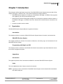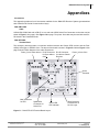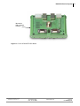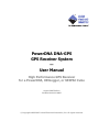
1
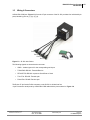
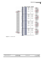
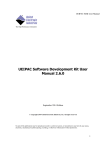
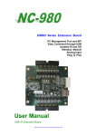
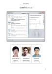
PowerDNA DNA-GPS GPS Receiver System — User Manual High Performance GPS Receiver for a PowerDNA, UEILogger, or UEIPAC Cube August 2007 Edition PN Man-DNA-GPS-0807 © Copyright 1998-2007 United Electronic Industries, Inc. All rights reserved. No part of this publication may be reproduced, stored in a retrieval system, or transmitted, in any form by any means, electronic, mechanical, by photocopying, recording, or otherwise without prior written permission. Information furnished in this manual is believed to be accurate and reliable. However, no responsibility is assumed for its use, or for any infringements of patents or other rights of third parties that may result from its use. All product names listed are trademarks or trade names of their respective companies. See UEI’s website for complete terms and conditions of sale: http://www.ueidaq.com/company/terms.aspx Contacting United Electronic Industries Mailing Address: 27 Renmar Avenue Walpole, MA 02081 U.S.A. For a list of our distributors and partners in the US and around the world, please see http://www.ueidaq.com/partners/ Support: Telephone: Fax: (508) 921-4600 (508) 668-2350 Also see the FAQs and online “Live Help” feature on our web site. Internet Support: Support Web-Site FTP Site [email protected] www.ueidaq.com ftp://ftp.ueidaq.com Product Disclaimer: WARNING! DO NOT USE PRODUCTS SOLD BY UNITED ELECTRONIC INDUSTRIES, INC. AS CRITICAL COMPONENTS IN LIFE SUPPORT DEVICES OR SYSTEMS. Products sold by United Electronic Industries, Inc. are not authorized for use as critical components in life support devices or systems. A critical component is any component of a life support device or system whose failure to perform can be reasonably expected to cause the failure of the life support device or system, or to affect its safety or effectiveness. Any attempt to purchase any United Electronic Industries, Inc. product for that purpose is null and void and United Electronic Industries Inc. accepts no liability whatsoever in contract, tort, or otherwise whether or not resulting from our or our employees' negligence or failure to detect an improper purchase. DNA-GPS Receiver System Table of Contents Chapter 1 Introduction .................................................... 1 1.1 Organization . . . . . . . . . . . . . . . . . . . . . . . . . . . . . . . . . . . . . . . . . . . . . . . . . . . . . . . . Introduction . . . . . . . . . . . . . . . . . . . . . . . . . . . . . . . . . . . . . . . . . . . . . . . . . . . DNA-GPS Receiver System . . . . . . . . . . . . . . . . . . . . . . . . . . . . . . . . . . . . . . Programming with High-Level API . . . . . . . . . . . . . . . . . . . . . . . . . . . . . . . . . . 1 1 1 1 1.2 The DNA-GPS Receiver System . . . . . . . . . . . . . . . . . . . . . . . . . . . . . . . . . . . . . . . . 3 1.3 Device Architecture. . . . . . . . . . . . . . . . . . . . . . . . . . . . . . . . . . . . . . . . . . . . . . . . . . . 4 1.4 DNA-SL-501 Layer capabilities. . . . . . . . . . . . . . . . . . . . . . . . . . . . . . . . . . . . . . . . . . 5 1.5 Wiring & Connectors . . . . . . . . . . . . . . . . . . . . . . . . . . . . . . . . . . . . . . . . . . . . . . . . . . 6 Chapter 2 Programming with the High Level API . . . . . . . . . . . . . . . . . . . . . . . . . . . . . . . 8 Appendix . . . . . . . . . . . . . . . . . . . . . . . . . . . . . . . . . . . . . . . . . . . . . . . . . . . . . . . . . . . . . . . . 14 Index . . . . . . . . . . . . . . . . . . . . . . . . . . . . . . . . . . . . . . . . . . . . . . . . . . . . . . . . . . . . . . . . . . 16 © Copyright ©2007 Copyright all rights 2007 reserved Scheidt & Bachmann USA United Electronic Industries, Inc. United Electronic Industries, Inc. Tel: 781-821-2890 Tel: 508-921-4600 Edit: TBD www.ueidaq.com Checked: TBD www.ueidaq.com Date:07. 31. 2007 Scheidt Date: 07.&31. Bachmann printed 2007 07. 31. 2007 File: DNA-GPSTOC.fm Vers: Draft Vers:1.0 1.1 File:DNA-GPSTOC.fm Fax: 781-821-2891 iii DNA-GPS Receiver System List of Figures Chapter 1 Introduction . . . . . . . . . . . . . . . . . . . . . . . . . . . . . . . . . . . . . . . . . . . . . . . . . . . . 1 1-1 DNA-GPS Receiver System and PowerDNA Cube ....................................................... 4 1-2 Block Diagram of DNA-GPS Receiver System Architecture.......................................... 5 1-3 SL-501 with Cables........................................................................................................ 6 1-4 SL-501 Pinout ................................................................................................................ 7 Appendix. . . . . . . . . . . . . . . . . . . . . . . . . . . . . . . . . . . . . . . . . . . . . . . . . . . . . . . . . . . . . . . . . . 9 A-1 DNA-STP-GPS Terminal Board Layout ....................................................................... 14 A-2 Photo of DNA-STP-GPS Board ................................................................................... 15 © Copyright ©2007 Copyright all rights 2007 reserved Scheidt & Bachmann USA United Electronic Industries, Inc. United Electronic Industries, Inc. Tel: 781-821-2890 Tel: 508-921-4600 Edit: TBD www.ueidaq.com Checked: TBD www.ueidaq.com Date:07. 31. 2007 Scheidt Date: 07.&31. Bachmann printed 2007 07. 31. 2007 File: DNA-GPSLOF.fm Vers: Draft Vers:1.0 1.1 File:DNA-GPSLOF.fm Fax: 781-821-2891 iii DNA-GPS Receiver System Introduction Chapter 1 Introduction This document outlines the feature set and use of the DNA-GPS Receiver System when used with a PowerDNA, UEILogger, or UEIPAC Cube. This manual describes the following products: 1.1 • DNA-GPS Receiver System for mounting on a PowerDNA, UEILogger, or UEIPAC Cube (supplied with a DNA-SL-501 Serial Communication Layer). • DNA-STP-GPS Terminal Panel Board, designed as a convenient connection interface between a PowerDNA, UEILogger, or UEIPAC Cube and a Garmin GPS 16-HVS Receiver mounted on the Cube • Accessory modules such as cables. Organization This DNA GPS Receiver System Manual is organized as follows: Introduction This chapter provides an overview of DNA-GPS Receiver System features, functions, and accessories. DNA-GPS Receiver System This chapter provides an overview of the device architecture, connectivity, logic, and accessories for the DNA-GPS Receiver System. Programming with High-Level API This chapter provides a reference to the DNA-SL-501 Serial Communication Layer User Manual for instruction on how to program the system. Appendices Accessories This appendix provides a list of accessories available for use with a DNA-GPS Receiver System. Index This is an alphabetical index of topics covered in this manual. NOTE: A glossary of terms used with the PowerDNA Cube and layers can be viewed and/or downloaded from www.ueidaq.com © Copyright ©2007 Copyright all rights 2007 reserved Scheidt & Bachmann USA United Electronic Industries, Inc. United Electronic Industries, Inc. Tel: 781-821-2890 Tel: 508-921-4600 Edit: TBD www.ueidaq.com Checked: TBD www.ueidaq.com Date:07. 31. 2007 Scheidt Date: 07.&31. Bachmann printed 2007 07. 31. 2007 File: GPS Chap1.fm Vers: Draft Vers:1.0 1.1 File:GPS Fax: 781-821-2891 Chap1.fm iii DNA-GPS Receiver System Introduction Manual Conventions To help you get the most out of this manual and our products, please note that we use the following conventions: Tips are designed to highlight quick ways to get the job done, or reveal good ideas you might not discover on your own. NOTE: Notes alert you to important information. CAUTION! Caution advises you of precautions to take to avoid injury, data loss, and damage to your boards or a system crash. Text formatted in bold typeface generally represents text that should be entered verbatim. For instance, it can represent a command, as in the following example: “You can instruct users how to run setup using a command such as setup.exe.” © Copyright ©2007 Copyright all rights 2007 reserved Scheidt & Bachmann USA United Electronic Industries, Inc. United Electronic Industries, Inc. Tel: 781-821-2890 Tel: 508-921-4600 Edit: TBD www.ueidaq.com Checked: TBD www.ueidaq.com Date:07. 31. 2007 Scheidt Date: 07.&31. Bachmann printed 2007 07. 31. 2007 File: GPS Chap1.fm Vers: Draft Vers:1.0 1.1 File:GPS Fax: 781-821-2891 Chap1.fm iv DNA-GPS Receiver System Introduction 1.2 The DNA-GPS Receiver System This manual describes the DNA-GPS Receiver System. It also describes the DNA-STP-GPS Terminal Panel accessory board. The technical specifications for the DNA-GPS Receiver System are listed in Table 1-1. Technical Specifications: GPS Receiver Positional Accuracy Velocity Accuracy Acquisition Times Reacquisition Cold acquisition Skysearch/Autolocate® 1 PPS Accuracy 1 PPS Display Output connection Serial Output Protocol Size Weight Operating Temperature Moisture resistance Power Supply Garmin GPS 16-HVS <3 meters in DGPS WAAS mode <15 meters in Standard mode 0.1 knot RMS less than 2 seconds approximately 45 seconds 5 minutes ±1 μS 1 PPS LED flash on DNA-STP-GPS board 5 meter cable, terminated in RJ-45. DNA-STP-GPS splits RJ-45 into easily used serial, power and 1 PPS connections NMEA 0183 v2 or v3 as well a variety of other ASCII sentences 3.58” diameter, 1.65” high 11.7 oz, with 5 meter cable -30°C to +85°C IEC 60539 IPX7 (immersion in 1 meter of water for 30 minutes) +9-36 VDC, less than 600 mW (fully compatible with standard PowerDNA power supplies) Table 1-1 DNA-GPS Receiver System Technical Specifications In WAAS mode, the Garmin GPS receiver provides location information with an error of less than 3 meters within areas served by WAAS (Wide Area Augmentation System), which basically means North America. WAAS is a system that broadcasts data that corrects standard GPS signals for errors caused by atmospheric and ionospheric disturbances and satellite orbit and clock drift. This broadcast signal can be received by the Garmin 16-HVS Receiver in WAAS mode. In areas where WAAS is not available, the GPS system provides location information with a positional error of less than 15 meters. The system also outputs a 1 PPS (pulse per second) signal that is synchronized to UTC time within ±1 microsecond. This signal provides a convenient means of synchronizing systems anywhere in the world. A green LED mounted on the DNA-STP-GPS accessory board indicates the current status of this signal. © Copyright ©2007 Copyright all rights 2007 reserved Scheidt & Bachmann USA United Electronic Industries, Inc. United Electronic Industries, Inc. Tel: 781-821-2890 Tel: 508-921-4600 Edit: TBD www.ueidaq.com Checked: TBD www.ueidaq.com Date:07. 31. 2007 Scheidt Date: 07.&31. Bachmann printed 2007 07. 31. 2007 File: GPS Chap1.fm Vers: Draft Vers:1.0 1.1 File:GPS Fax: 781-821-2891 Chap1.fm v DNA-GPS Receiver System Introduction A DNA-STP-GPS terminal board is supplied as a standard accessory with each GPS Receiver system to facilitate the connections between the Garmin unit and the associated Cube. As illustrated in Figure 1-2 and also in Figure A-1 in the Appendix, this board connects the receiver signal from the Garmin unit to two RJ-45 connectors, one of which is used for two DB-9 Serial Line connectors, and one of which is used for the Sync input to the Cube. The accessory board also provides a BNC connector that can be used to output the 1PPS GPS signal for synchronizing other devices to UTC time. An LED mounted on the board flashes with the 1 PPS signal, confirming satellite synchronization and presence of the signal Figure 1-1 is a photo of the DNA-GPS Receiver System mounted on a PowerDNA Cube. NOTE: Cube must have at least one DNA-SL-501 Serial Comm. Layer Figure 1-1. DNA-GPS Receiver System and PowerDNA Cube 1.3 Device Architecture The DNA-GPS Receiver System consists of a Garmin GPS 16-HVS receiver mounted on the top of a PowerDNA, UEILogger, or UEIPAC Cube, as shown in Figure 1-1. The Cube contains at least one DNA-SL-501 Serial Communication layer board. The system is usually provided with additional accessory items such as RS-232/485 serial cables, power supply cables, Sync cable, and a DNA-STP-GPS terminal panel that facilitates the various connections between the Garmin receiver and the Cube. These accessories are described more fully in the Appendix on page 14. A functional block diagram of the major components of a complete PowerDNA, UEILogger, or UEIPAC GPS system is shown in Figure 1-2. The diagram shows the interconnections between the Garmin receiver, an associated Cube, and a DNA-STP-GPS terminal board © Copyright ©2007 Copyright all rights 2007 reserved Scheidt & Bachmann USA United Electronic Industries, Inc. United Electronic Industries, Inc. Tel: 781-821-2890 Tel: 508-921-4600 Edit: TBD www.ueidaq.com Checked: TBD www.ueidaq.com Date:07. 31. 2007 Scheidt Date: 07.&31. Bachmann printed 2007 07. 31. 2007 File: GPS Chap1.fm Vers: Draft Vers:1.0 1.1 File:GPS Fax: 781-821-2891 Chap1.fm vi DNA-GPS Receiver System Introduction DNA-STP-GPS GPS RJ-45 Garmin 16-HVS Receiver (with WAAS capability) Sync Connector 9-pin “D” RS-232 Connection Power Connection PPS LED Power SL-501 Serial Port Connection Sync Port Connection PowerDNA Cube The DNA-STP-GPS provides connections from the GPS to: • Power • The two independent GPS serial ports • The 1 PPS GPS synchronization pulse Figure 1-2 . Block Diagram of DNA-GPS Receiver System Architecture 1.4 DNA-SL-501 Layer capabilities Since the DNA-GPS Receiver System requires a DNA-SL-501 layer to be supplied with the Cube, the following information about the SL-501 is included in this manual. For more detailed information, refer to the SL-501 User Manual and Datasheet. Using the RS-232 or RS-485 standard, the controller is capable of communicating at speeds of 256Kbit/s for RS-232 and 1Mbit/s for RS-485. When in RS-485 mode, the layer is compatible with RS-422 networks. The UART16550 runs at a base-block frequency of 66MHz, with a FIFO size of 2048. Each port has independently programmable: • Baud/bit rate • UART interrupt • Timeout interrupt • TX/RX FIFO interrupt • Error interrupt (4 per port) © Copyright ©2007 Copyright all rights 2007 reserved Scheidt & Bachmann USA United Electronic Industries, Inc. United Electronic Industries, Inc. Tel: 781-821-2890 Tel: 508-921-4600 Edit: TBD www.ueidaq.com Checked: TBD www.ueidaq.com Date:07. 31. 2007 Scheidt Date: 07.&31. Bachmann printed 2007 07. 31. 2007 File: GPS Chap1.fm Vers: Draft Vers:1.0 1.1 File:GPS Fax: 781-821-2891 Chap1.fm vii DNA-GPS Receiver System Introduction 1.5 Wiring & Connectors A DNA-CBL-COM (see Figure 1-3) from the 37-pin connector of the SL-501 provides four individual 9-pin ports, labeled by port as (1), (2), (3), (4). Port 1 Port 2 Port 4 Port 3 Figure 1-3. SL-501 with Cables The following signals are located at the connector: • GNDx - Isolated ground for the corresponding serial port • TXDx/RXDx RS-232: Transmit/Receive • RTSx/RCTSx RS-232: request to Send/Clear to Send • TXx+/TXx- RS-485: Transmit pair • RXx+/RXx- RS-485: Receive pair The B-size 37-pin female D-Sub connector on the SL-501 is divided into four 9-pin D-connector serial ports by a DNA-CBL-COM cable with the pinout shown in Figure 1-4. © Copyright ©2007 Copyright all rights 2007 reserved Scheidt & Bachmann USA United Electronic Industries, Inc. United Electronic Industries, Inc. Tel: 781-821-2890 Tel: 508-921-4600 Edit: TBD www.ueidaq.com Checked: TBD www.ueidaq.com Date:07. 31. 2007 Scheidt Date: 07.&31. Bachmann printed 2007 07. 31. 2007 File: GPS Chap1.fm Vers: Draft Vers:1.0 1.1 File:GPS Fax: 781-821-2891 Chap1.fm viii DNA-GPS Receiver System Introduction Figure 1-4 . SL-501 Pinout © Copyright ©2007 Copyright all rights 2007 reserved Scheidt & Bachmann USA United Electronic Industries, Inc. United Electronic Industries, Inc. Tel: 781-821-2890 Tel: 508-921-4600 Edit: TBD www.ueidaq.com Checked: TBD www.ueidaq.com Date:07. 31. 2007 Scheidt Date: 07.&31. Bachmann printed 2007 07. 31. 2007 File: GPS Chap1.fm Vers: Draft Vers:1.0 1.1 File:GPS Fax: 781-821-2891 Chap1.fm ix DNA-GPS Receiver System Programming with the High Level API Chapter 2 Programming with the High Level API Since the DNA-GPS Receiver System requires that a DNA-SL-501 Serial Communication layer be installed in the associated PowerDNA, UEILogger, or UEIPAC Cube, please refer to the code examples for the DNASL-501 Layer included with the PowerDNA Software Suite provided with your Cube. One of these examples is shown below. //===================================================================== // // NAME: SampleGPS.c // // DESCRIPTION: // // This example shows how to interface with a GARMIN GPS receiver. // It continuously read incoming NMEA messages on serial port 0 in // a dedicated thread. // The main thread is configured to handle the 1 PPS timing // signal coming from the GPS (You need to connect that signal to // PowerDNA's SyncIn connector with the DNA-GPS-STP terminal block). // // // ----------------------------------------------------------------// // Copyright (C) 2006 United Electronic Industries, Inc. // All rights reserved. // United Electronic Industries Confidential Information. // //=================================================================== #include <stdio.h> #include <stdint.h> #include <stdlib.h> #include <netinet/in.h> #include <unistd.h> #include <signal.h> #include <math.h> #include <sys/time.h> #include <sched.h> #include <pthread.h> #include "PDNA.h" #include "ParseParams.h" #include "nmeap.h" static nmeap_context_t nmea; /* parser context */ static nmeap_gga_t gga; /* this is where the data from GGA /* messages will show up */ static nmeap_rmc_t rmc; /* this is where the data from RMC /* messages will show up */ // The GPS is sending data at 9600bps 8N1 #define CHANNEL_CFG DQCFG_501(DQ_SL501_OPER_NORM, \ © Copyright ©2007 Copyright all rights 2007 reserved Scheidt & Bachmann USA United Electronic Industries, Inc. United Electronic Industries, Inc. Tel: 781-821-2890 Tel: 508-921-4600 Edit: TBD www.ueidaq.com Checked: TBD www.ueidaq.com Date:07. 31. 2007 Scheidt Date: 07.&31. Bachmann printed 2007 07. 31. 2007 File: GPS Chap2.fm Vers: Draft Vers:1.0 1.1 File:GPS Fax: 781-821-2891 Chap2.fm iii DNA-GPS Receiver System Programming with the High Level API DQ_SL501_MODE_232, \ DQ_SL501_BAUD_9600, \ DQ_SL501_WIDTH_8, \ DQ_SL501_STOP_1, \ DQ_SL501_PARITY_NONE) int stop = 0; PDNA_PARAMS params = { 0, 1, {0}, 100.0 }; int handle = 0; // Handler for SIGINT void signalhandler(int sig) { stop = 1; } static void print_gga(nmeap_gga_t *gga) { printf("Latitude = %.6f\n" "Longitude = %.6f\n" "Altitude = %.0f m\n" "Time = %lu\n" "Satellites = %d\n" "Quality = %d\n" "HDOP = %f\n" "geoid = %f\n", gga->latitude , gga->longitude, gga->altitude , gga->time , gga->satellites, gga->quality , gga->hdop , gga->geoid); } void* SerialReadThreadProc(void *arg) { int ret = DQ_SUCCESS; sigset_t set; #define BUFSIZE 128 char buffer[BUFSIZE]; sigemptyset(&set); sigaddset(&set, SIGINT); pthread_sigmask(SIG_BLOCK, &set, NULL); ret = nmeap_init(&nmea, NULL); if (ret != 0) { fprintf(stderr, "nmeap_init %d\n",ret); return NULL; } © Copyright ©2007 Copyright all rights 2007 reserved Scheidt & Bachmann USA United Electronic Industries, Inc. United Electronic Industries, Inc. Tel: 781-821-2890 Tel: 508-921-4600 Edit: TBD www.ueidaq.com Checked: TBD www.ueidaq.com Date:07. 31. 2007 Scheidt Date: 07.&31. Bachmann printed 2007 07. 31. 2007 File: GPS Chap2.fm Vers: Draft Vers:1.0 1.1 File:GPS Fax: 781-821-2891 Chap2.fm iv DNA-GPS Receiver System Programming with the High Level API /* add standard GPGGA parser */ ret = nmeap_addParser(&nmea,"GPGGA",nmeap_gpgga,NULL,&gga); if (ret != 0) { fprintf(stderr, "nmeap_add %d\n",ret); return NULL; } /* add standard GPRMC parser */ ret = nmeap_addParser(&nmea,"GPRMC",nmeap_gprmc,NULL,&rmc); if (ret != 0) { fprintf(stderr, "nmeap_add %d\n",ret); return NULL; } while(!stop) { int bufferLength; ret = DqEmb501Receive(handle, params.device, params.channels[0], (unsigned char*)buffer, BUFSIZE, 2000, '\n'); if(ret < 0) { printf("Error %d receiving from serial port\n", ret); break; } bufferLength = ret; buffer[bufferLength] = '\0'; //printf("%s", buffer); // Send message to parser ret = nmeap_parseBuffer(&nmea, buffer, &bufferLength); /* process the return code */ switch (ret) { case NMEAP_GPGGA: /* GOT A GPGGA MESSAGE */ print_gga(&gga); break; case NMEAP_GPRMC: /* GOT A GPRMC MESSAGE */ //print_rmc(&rmc); break; default: break; } } return NULL; } © Copyright ©2007 Copyright all rights 2007 reserved Scheidt & Bachmann USA United Electronic Industries, Inc. United Electronic Industries, Inc. Tel: 781-821-2890 Tel: 508-921-4600 Edit: TBD www.ueidaq.com Checked: TBD www.ueidaq.com Date:07. 31. 2007 Scheidt Date: 07.&31. Bachmann printed 2007 07. 31. 2007 File: GPS Chap2.fm Vers: Draft Vers:1.0 1.1 File:GPS Fax: 781-821-2891 Chap2.fm v DNA-GPS Receiver System Programming with the High Level API int main(int argc, char* argv[]) { int ret = 0; double duration; int count = 0; struct timeval tv1, tv2; pthread_t recvThread; DqInitDAQLib(); ParseParameters(argc, argv, ¶ms); signal(SIGINT, signalhandler); // open communication with IOM and receive IOM crucial // identification data if ((ret = DqOpenIOM("127.0.0.1", DQ_UDP_DAQ_PORT, 2000, &handle, NULL)) < 0) { printf("Error %d In Initializing Communication with IOM\n", ret); return ret; } // set channel configuration if ((ret = DqAdv501SetChannelCfg(handle, params.device, params.channels[0], CHANNEL_CFG)) < 0) { printf("error %d in DqAdv501SetChannelCfg()\n", ret); goto finish_up; } if ((ret = DqAdv501SetTimeout(handle, params.device, params.channels[0], 1000)) < 0) { // 1 second timeout for xmit printf("error %d in DqAdv501SetTimeout\n", ret); goto finish_up; } if ((ret = DqAdv501SetTermLength(handle, params.device, params.channels[0], 1)) < 0) { // 8 bytes at a time printf("error %d in DqAdv501SetTermLength\n", ret); goto finish_up; } if ((ret = DqAdv501SetWatermark(handle, params.device, params.channels[0], DQL_IOCTL501_SETTXWM, 1)) < 0) { // internal // fifos @ 512 printf("error %d in DqAdv501SetWatermark TX", ret); goto finish_up; } if ((ret = DqAdv501SetWatermark(handle, params.device, params.channels[0], DQL_IOCTL501_SETRXWM, 1)) < 0) { printf("error %d in DqAdv501SetWatermark RX\n", ret); goto finish_up; } if ((ret = DqAdv501Enable(handle, params.device, TRUE)) < 0) { © Copyright ©2007 Copyright all rights 2007 reserved Scheidt & Bachmann USA United Electronic Industries, Inc. United Electronic Industries, Inc. Tel: 781-821-2890 Tel: 508-921-4600 Edit: TBD www.ueidaq.com Checked: TBD www.ueidaq.com Date:07. 31. 2007 Scheidt Date: 07.&31. Bachmann printed 2007 07. 31. 2007 File: GPS Chap2.fm Vers: Draft Vers:1.0 1.1 File:GPS Fax: 781-821-2891 Chap2.fm vi DNA-GPS Receiver System Programming with the High Level API printf("Error %d in DqAdv501Enable()\n", ret); goto finish_up; } // Start thread that will read position data comming from the GPS pthread_create(&recvThread, NULL, SerialReadThreadProc, NULL); ret = DqEmbConfigureEvent(handle, DqEmbEventSyncIn, 0); if(ret < 0) { fprintf(stderr, "Error %d configuring event\n", ret); return ret; } gettimeofday(&tv1, NULL); while(!stop) { DQ_EMBEDDED_EVENT evt; ret = DqEmbWaitForEvent(handle, 2000, &evt); if(ret < 0) { fprintf(stderr, "Error %d configuring event\n", ret); return ret; } if(evt & DqEmbEventTimeout) printf("Timeout event\n"); if(evt & DqEmbEventSyncIn) printf("SyncIn event\n"); //usleep(100000); count++; } gettimeofday(&tv2, NULL); duration = ((tv2.tv_sec-tv1.tv_sec) + (tv2.tv_usec-tv1.tv_usec)/ 1000000.0); printf("Executed %d iterations in %f s (%f updates per sec.)\n", count, duration, count/duration); ret = DqEmbCancelEvent(handle, DqEmbEventSyncIn); if(ret < 0) { fprintf(stderr, "Error %d cancelling event\n", ret); return ret; } pthread_join(recvThread, NULL); finish_up: if ((ret = DqAdv501Enable(handle, params.device, FALSE)) < 0) { © Copyright ©2007 Copyright all rights 2007 reserved Scheidt & Bachmann USA United Electronic Industries, Inc. United Electronic Industries, Inc. Tel: 781-821-2890 Tel: 508-921-4600 Edit: TBD www.ueidaq.com Checked: TBD www.ueidaq.com Date:07. 31. 2007 Scheidt Date: 07.&31. Bachmann printed 2007 07. 31. 2007 File: GPS Chap2.fm Vers: Draft Vers:1.0 1.1 File:GPS Fax: 781-821-2891 Chap2.fm vii DNA-GPS Receiver System Programming with the High Level API printf("Error %d in DqAdv501Enable()\n", ret); } if (handle) { DqCloseIOM(handle); } DqCleanUpDAQLib(); return 0; } © Copyright ©2007 Copyright all rights 2007 reserved Scheidt & Bachmann USA United Electronic Industries, Inc. United Electronic Industries, Inc. Tel: 781-821-2890 Tel: 508-921-4600 Edit: TBD www.ueidaq.com Checked: TBD www.ueidaq.com Date:07. 31. 2007 Scheidt Date: 07.&31. Bachmann printed 2007 07. 31. 2007 File: GPS Chap2.fm Vers: Draft Vers:1.0 1.1 File:GPS Fax: 781-821-2891 Chap2.fm viii DNA-GPS Receiver System Appendices Accessories This appendix provides a list of accessories available for the DNA-GPS Receiver System (preassembled with a DNA-SL-501 Serial Communication Layer). DNA-CBL-COM Cable A DNA-CBL-COM Cable with a DB-37 on one end and 4 DB-9 Serial Port Connectors on the other end as shown in Figure 1-3 on page 6. See Figure 1-4 on page 7 for pinout. One cable may be used with each SL501 board in the PowerDNA Cube. DNA-STP-GPS Terminal Panel This accessory board provides a convenient interface between the Garmin GPS receiver and the PowerDNA, UEILogger, or UEIPAC Cube. The layout of the board is shown in Figure A-1 below. Figure 1-2 on page 5 shows a block diagram of the cable connections. Power_Out to other devices RJ-45 Connector RJ-45 Connector for Sync cable to for cable to Garmin Cube Receiver Power_In from Cube Screw Terminals BNC Connector for PPS Spare DB-9 Connector for Serial Port Green LED PPS Indicator DB-9 Connector to Serial Port on SL-501 Layer Figure 1-1. DNA-STP-GPS Terminal Board Layout © Copyright ©2007 Copyright all rights 2007 reserved Scheidt & Bachmann USA United Electronic Industries, Inc. United Electronic Industries, Inc. Tel: 781-821-2890 Tel: 508-921-4600 Edit: TBD www.ueidaq.com Checked: TBD www.ueidaq.com Date:07. 31. 2007 Scheidt Date: 07.&31. Bachmann printed 2007 07. 31. 2007 File: GPSAppx.fm Vers: Draft Vers:1.0 1.1 Fax: File:GPSAppx.fm 781-821-2891 iii DNA-GPS Receiver System Mounted in DIN rail plastic housing Figure 1-2. Photo of DNA-STP-GPS Board © Copyright ©2007 Copyright all rights 2007 reserved Scheidt & Bachmann USA United Electronic Industries, Inc. United Electronic Industries, Inc. Tel: 781-821-2890 Tel: 508-921-4600 Edit: TBD www.ueidaq.com Checked: TBD www.ueidaq.com Date:07. 31. 2007 Scheidt Date: 07.&31. Bachmann printed 2007 07. 31. 2007 File: GPSAppx.fm Vers: Draft Vers:1.0 1.1 Fax: File:GPSAppx.fm 781-821-2891 iv DNA-GPS Receiver System 16 Index Numerics M 1 PPS Signal 3 63826 Figure Caption A Figure 1-4 . Logic Block Diagram SL-501 Pinout 7 Accessories D Mailing Address ii Manual Conventions 14 F Functional Block Diagram G Garmin GPS 16-HVS Internet Support Introduction 1 Photo 4 Positional Error 3 Product Disclaimer Programming 8 2 ii R DNA-CBL-COM Cable 6, 14 DNA-GPS Receiver System 3 DNA-SL-501 Layer 5 DNA-SL-501 Serial Communication DNA-STP-GPS Terminal Board 4 DNA-STP-GPS Terminal Panel 14 I P RS-232/485 4 S 4 4 Sample Code 8 SL-501 Pinout 7 Support ii Sync 4 T Technical Specifications 3 Terminal Board Layout 14 U 4 UART16550 UTC Time 3 ii W WAAS © Copyright 2007 United Electronic Industries, Inc. Tel: 5008-921-4600 Date: 07. 31. 2007 5 3 www.ueidaq.com File: Vers: 1.1 DNA-GPSIX.fm