1
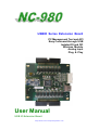
USBIO Series Extension Board
PC Management Tool and API
Easy Command through USB
Isolated DI and DO
Wireless Module
Analog Input
Plug & Play
User Manual
USB IO Extension Board
http://www.microcomputersystems.com
Copyright Notice
Copyright ©2011
All rights reserved.
Reproduction without permission is prohibited.
Disclaimer
Information in this document is subject to change without notice and does not
represent a commitment on the part of we
We provides this document “as is”, without warranty of any kind, either
expressed or implied, including, but not limited to, its particular purpose. We
reserves the rights to make improvements and/or changes to this manual, or
to the products and/or the programs described in this manual at any time.
Information provided in this manual is intended to be accurate and reliable.
However, We assumes no responsibility for its use, or for any infringements on
the rights of third parties that may result from its use.
The product might include unintentional technical or typographical errors.
Changes are periodically made to the information herein to correct such errors,
and these changes are incorporated into new editions of the publication.
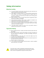
Safety Information
Electrical safety
z
z
z
z
z
z
To prevent electrical shock hazard, disconnect the power cable from the
electrical outlet before relocating the system.
When adding or removing devices to or from the system, ensure that the
power cables for the devices are unplugged before the signal cables are
connected. If possible, disconnect all power cables from the existing system
before you add a device.
Before connecting or removing signal cable from the single board, ensure
that all power cables are unplugged.
Seek professional assistance before using an adapter or extension cord.
These devices could interrupt the grounding circuit.
Make sure that your power supply is set to the correct voltage in your area.
If you are not sure about the voltage of the electrical outlet you are using,
contact your local power company.
If the power supply is broken, do not try to fix it by yourself. Contact a
qualified service technician or your retailer.
Operation Safety
z Before installing the device, carefully read all the documents that came with
the package.
z Before using the product, make sure all cables are correctly connected and
the power cables are not damaged. If you detect any damage, contact your
dealer immediately.
z To avoid short circuits, keep paper clips, screws and staples away from
connectors, slots, sockets and circuitry.
z Avoid dust, humidity, and temperature extremes. Do not place the product in
any area where it may become wet.
z Place the product on a stable surface.
z If you encounter technical problems with the product, contact a qualified
service technician or your retailer.
The symbol of the crossed out wheeled bin indicated that the product
(electrical and electronic equipment) should not be placed in municipal
waste. Check local regulations for disposal of electric products.
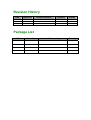
Revision History
Date
Improved
2011-7-14
Revised Location
Revision
V0.1 Draft
Author
Kara, Cater
Package List
HW
Quantity
Installation package
Quantity
Content
Disclaimer ......................................................................................................................... 2
Safety Information ............................................................................................................. 3
Electrical safety.......................................................................................................... 3
Operation Safety ........................................................................................................ 3
Revision History ................................................................................................................ 4
Package List ..................................................................................................................... 4
Chapter 1 Product Introduction ......................................................................................... 3
1.1 Features............................................................................................................... 3
1.2 Specifications ....................................................................................................... 4
1.3 Block Diagram...................................................................................................... 5
1.4 Mechanical Information ........................................................................................ 6
Chapter2 Extension Connectors ....................................................................................... 7
2.1 Connector Assignment......................................................................................... 7
2.2 USB Port .............................................................................................................. 8
2.3 MIO Port............................................................................................................... 9
2.4 Optional Port ...................................................................................................... 10
2.5 Isolated DO Port ................................................................................................ 10
2.6 Isolated DI Port .................................................................................................. 12
Chapter3 How to Start NC-980 ....................................................................................... 14
3.1 Connect NC-980 to PC through USB................................................................. 14
3.2 Install Driver NCUSB.......................................................................................... 15
3.3
USB Terminal Software Tool - aUSBTerm ..................................................... 20
Chapter 4 Command Set ................................................................................................ 23
4.1
Command Set Format ................................................................................... 23
4.2
Command List ............................................................................................... 24
4.3
IO Command Description .............................................................................. 24
4.3.1
IO Reset ............................................................................................. 24
4.3.2
Default IO Mode ................................................................................. 24
4.3.3
Disable Alarm ..................................................................................... 25
4.3.4
Enable Alarm ...................................................................................... 25
4.3.5
Set IO as Digital Input......................................................................... 26
4.3.6
Set IO as Digital Output...................................................................... 26
4.3.7
Test IO Pin.......................................................................................... 26
4.3.8
Get IO Data ........................................................................................ 27
4.3.9
Set IO ................................................................................................. 27
4.3.10 Reset IO ............................................................................................. 28
4.3.11 Write To Port....................................................................................... 28
4.3.12 Write To Port....................................................................................... 29
4.3.13 Set IO Mode ....................................................................................... 29
4.3.14 Set Up Limit for Analog Input.............................................................. 30
4.3.15 Set Low Limit for Analog Input ............................................................ 30
4.3.16 Set Default Limit for ADC Alarm.......................................................... 30
4.3.17 Write Parameter into Flash ................................................................. 31
4.3.18 Read back Parameter from Flash....................................................... 31
4.3.19 Send Data to COM1 ........................................................................... 31
4.3.20 Configure COM1 Baud Rate............................................................... 32
4.3.21 Send Data to COM2 ........................................................................... 32
4.3.22 Configure COM2 Baud Rate............................................................... 33
4.3.23 Set PWM Generator ........................................................................... 34
4.3.24 Configure PWM Generator ................................................................. 34
4.4
RFIO Command Description ......................................................................... 35
4.4.1
S-Node(My Node) Address................................................................. 36
4.4.2
D-Node(To Node) Address ................................................................. 36
4.4.3
Ensure Connection between Nodes ................................................... 37
4.4.4
Send a Data Packet through RF......................................................... 37
4.4.5
Send a Remote IO Control through RF .............................................. 39
4.4.6
Set De/Encryption Key words ............................................................. 39
4.4.7
Nodes Connection Monitor ................................................................. 40
4.4.8
Measure and Display RSSI ................................................................ 40
4.4.9
WhoOnSky ......................................................................................... 41
4.4.10 Set RF Parameter............................................................................... 41
4.4.11 Shutdown RF Module ......................................................................... 42
4.4.12 Wakeup RF Module ............................................................................ 42
4.4.13 CW(Continue Wave) Generator.......................................................... 42
4.4.14 Test Command: Quick Set Node Address .......................................... 43
4.4.15 Test Comand: Display All Node Address ............................................ 43
4.4.16 Test Command: Send Out a ACK Packet ........................................... 44
4.4.17 Test Command: Encryption and Decryption ....................................... 44
4.4.18 Test Command: Erase Parameters from Flash................................... 45
Chapter 5 Programming.................................................................................................. 46
5.1 Overview ............................................................................................................ 46
5.2
Programming on PC...................................................................................... 46
5.2.1
Process chart ..................................................................................... 46
5.2.2
API Summary (Windows operation system) ....................................... 47
5.2.3
Example ............................................................................................. 47
5.2
USB Programming on WinCE ....................................................................... 51
5.2.1
Process chart ..................................................................................... 51
5.2.2
API Summary (WinCE system)........................................................... 51
5.2.3
Example ............................................................................................. 52
Chapter 1 Product Introduction
NC-980 is a multiple IO extension board under USBIO products series that could be
accessed by different PC or any host computer over USB or Wireless. NC-980 is
designed for PC-104 form factor, connecting to PC/host computer through USB port.
User could command NC-980 Board by command set through USB or RF Module. This
NC-980 is a plug & Play Extension Board for users’ application, easily integrated into
users’ system.
NC-980 provides screwing connectors of each Digital Input and Output for easy wiring
connection.
You could use multiple NC-980 Boards to link with a host computer.
NC-980 has low power dissipation, whose power supply is from USB port.
NC-980 Board has a wireless interface. It provides an intelligent wireless connection
management, Auto RF power control, Auto-Frequency Calibration to reach a long-range
wireless communication and power saving. On-board 32-bit controller handles wireless
communication with high efficiency and excellent power management. The board is able
to connect to host/PC through USB or RS485. You could use aUSBTerm Software to
control NC-980. aUSBTerm is a terminal software through USB port that user could input
command to control NC-980 device. Software API is also available, so user could make
his own application software.
NC-980’s Digital I/O terminals are fully isolated on electrical consideration, suitable for
different industrial environment at safety and reliability.
1.1 Features
PC104 form factor, USB IO Extension Board
Isolated DI and DO
Analog Input
Wireless Module
Plug & Play
Easy Command Set through USB
PC Management Tool and API
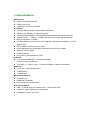
1.2 Specifications
USB Interface
z USB 2.0 Full Speed Interface
z USB Device Driver
z USBAssist Tool and API provided
RF Interface
z Topology: Node to Node, or Master/Slave Networking
z 4 Byte Group Address and 4 Byte IP Address
z 315/433/868/915/950MHz UHF ISM Predefined Frequency Band, Multi-Channels
z Transmit Power : +10dBm ~ +20dBm, Auto RF Power Output Adjustment Mode
z Receive Sensitivity: -115 dBm
z Excellent Wireless Communication over Distance, Long Range transmission, >1~2Km
@Open Area
z Up to 128Kbps Data Transmission Rate
z Power Management by Sleep Mode, Idle Mode and Power Down Mode
z Wake Up from RF Signal
z External Antenna
z Encryption by user defined key words
Isolated IO
z 16 ch Isolated Digital Input, 3500Vacrms Isolated
4V-24Vdc Input, individual set
z
16 ch SSR, +/- 350Vac or Vdc, +/-130mA Drive ability, 3000Vac rms Isolation
Multiple IO
z 8-ch 0-10V , 12bit Resolution ADC
z 1x RS232 Port
z 1x RS485 Port
API Software Interface
z
Command Set
z
USBAssist Tool Ready
z API for customers’ development
Physical Information
z
USB 5V Power Supply or External 4Vdc ~ 12Vdc Power Input
z
Dimension: 96mm x 90mm PC104 Standard
z
Temperature range: -20 to +80℃
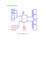
1.3 Block Diagram
Figure1-1: NC-980 Block Diagram
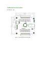
1.4 Mechanical Information
Unit: Millimeter(MM)
Figure 1-2: NC-980 Mechanical Information
Chapter2 Extension Connectors
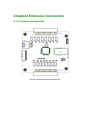
2.1 Connector Assignment
Figure 2-1: Extension Connector on Board Top
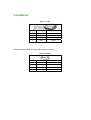
2.2 USB Port
Table 2-1: USB1
Pin
Pin Assignment
Functional specification
1
5V
VCC
2
USB-
Data-
3
USB+
Data+
4
GND
Ground
USB-J2 is the pin similar as USB1 with different connector.
Table 2-2: USB-J2
Pin
Pin Assignment
Functional specification
1
5V
VCC
2
USB-
Data-
3
USB+
Data+
4
GND
Ground
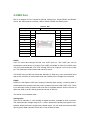
2.3 MIO Port
MIO is a multiple IO Port, includes 8-channel Analog Input, simple RS232 and RS485.
Hence, NC-980 becomes converter, USB to RS232, RS485 and Analog Input.
Table 2-3: MIO
CN1
AI & RS485 & RS232 & CAN & DCIN
Pin Assignment
Pin
AI1
Drawing
Pin
Pin Assignment
1
2
AI0
AI3
3
4
AI2
AI5
5
6
AI4
AI7
7
8
AI6
GND
9
10
GND
485A
11
12
CTS
485B
13
14
RTS
NC
15
16
RXD
NC
17
18
TXD
GND
19
20
DCIN 5V
RS232
User can send data through NC-980 over UART port too. This UART port can be
connected to usual device or PC/Host. This UART is available on MIO Port. RS232 uses
TxD, RxD, and handshake CTS, RTS. Actually, RTS is an output pin, but CTS is an input
pin. This COM port communicates with usual IO device.
This UART does provide auto baud rate detection by Enter key. User could define baud
rate by NC command or enable Auto-baud rate. Please refer to Chapter NC Command
RS485
RS485 is a half duplex UART port, keeping in listening state usually, a receiving state. It
will be switched to transmit mode only when a packet come from USB, UART or RF. There
is no terminator inside, therefore user must add in a parallel resistor around 100 ohm to
485A and 485B, if the NC-980 is placed at end side of 485 bus.
This 485 is in non-isolated mode.
Analog Input
There are 8 channels of 12-bit Analog to Digital converter, available on MIO connector.
The measured input voltage range is 0V ~ 10Vdc. Because the analog input pins are nonisolated, please ensure the proper input voltage range. You can read the measured ADC
data by get IO Data command of NC-980, or any remote NC-980.
2.4 Optional Port
This is an optional port, may be example of LED port.
Table 2-4: IO
IO & I2C
CN1
Pin Assignment
Pin
IO0
Drawing
Pin
Pin Assignment
1
2
IO1
IO2
3
4
IO3
IO4
5
6
IO5
IO6
7
8
IO7
SCL
9
10
SDA
GND
11
12
3V3
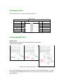
2.5 Isolated DO Port
Digital Output
Digital outputs are often used to control other electrical devices.
Here are some examples.
Figure2.3.2 Internal Connection of Digital Output
DO, each isolated digital output, uses Opto-SSR, a small Solid-State-Relay. The SSR
could supply 120mA@350Vac or 350Vdc. You could refer to any one of above charts for
user application.
Chart left: use DC power, DC must be lower than 350Vdc, as light loading <120mA.
Chart middle: use AC Power, AC must be lower than 350Vac, as loading < 120mA
Chart right: use an external TRIAC to increase Power driving capacity, its driving capacity
depends on TRIAC. User could choose a proper TRIAC in user’s application.
Table 2-5: DO
DIO-OUT
DO0~DO15
Pin Assignment
Pin
Pin
Pin Assignment
DOA0
1
2
DOB0
DOA1
3
4
DOB1
DOA2
5
6
DOB2
DOA3
7
8
DOB3
DOA4
9
10
DOB4
DOA5
11
12
DOB5
DOA6
13
14
DOB6
DOA7
15
16
DOB7
DOA8
17
18
DOB8
DOA9
19
20
DOB9
DOA10
21
22
DOB10
DOA11
23
24
DOB11
DOA12
25
26
DOB12
DOA13
27
28
DOB13
DOA14
29
30
DOB14
DOA15
31
32
DOB15
NC
33
34
NC
2.6 Isolated DI Port
Isolated Digital inputs use opto-coupler to isolate external voltage, that will turn on inner
circuit by applying a proper voltage on V+ and V-. Inner circuit will be trigged when V+ and
V- are higher than 1.5V, whose maximum applying voltage is 24V.
The isolated circuit makes input side and inner circuit independent, but can transfer signal
to inner circuit.
The isolated voltage is up to 3000V, therefore, please make clean of this zone from
opto-coupler to the connector.
Figure 2-3: Internal Connection of Digital Input
Table 2-6: DI
DIO-IN
DI0~DI15
Pin Assignment
Pin
Pin
Pin Assignment
DI0+
1
2
DI0-
DI1+
3
4
DI1-
DI2+
5
6
DI2-
DI3+
7
8
DI3-
DI4+
9
10
DI4-
DI5+
11
12
DI5-
DI6+
13
14
DI6-
DI7+
15
16
DI7-
DI8+
17
18
DI8-
DI9+
19
20
DI9-
DI10+
21
22
DI10-
DI11+
23
24
DI11-
DI12+
25
26
DI12-
DI13+
27
28
DI13-
DI14+
29
30
DI14-
DI15+
31
32
DI15-
NC
33
34
NC
Chapter3 How to Start NC-980
Here briefs how to setup and identify quickly.
z
z
z
z
z
Prepare necessary parts
One PC, Double side USB-A Cable, NC-980 and Software CD.
Install NCUSB driver in PC for NC-980.
Connect NC-980 and PC with a USB cable, USB-A type (as Chapter 3.1 below)
Run aUSBTerm software on PC
Give your command on aUSBTerm.
0x3E,0x66,0x0D,0x00,0x55 … then you could see LED Light-On on NC-980, if the
connection is setup well.
z You could give more command through aUSBTerm, or develop your software
The section below will show the details.
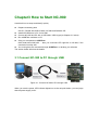
3.1 Connect NC-980 to PC through USB
Figure 3-1: Connect NC-980 to PC through USB
When you see the power LED indicator lighted on as the red point below, you can judge
that the power supply is OK.
Figure 3-2: NC-980 LED Indicator
Attention: The LED indicator may be red or green up to the manufacture.
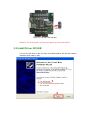
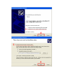
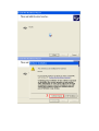
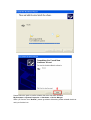
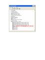
3.2 Install Driver NCUSB
You can find the driver in the CD which is packed together with NC-980. Please
install the driver step by step.
Please follow the path to confirm whether the driver has been installed:
My Computer ->System Properties -> Hardware -> Device Manger
When you find the icon "NcUsb", please go ahead. Otherwise, please reinstall the driver
until you find the icon.
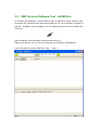
3.3 USB Terminal Software Tool - aUSBTerm
PC software tool aUSBTerm, offers similar function as Microsoft’s Hyper Terminal. User
could input NC Command to NC-980 through USB Port, so it is convenient and simple to
operate. aUSBTerm.exe is available in the CD together with the driver of NC-980. Here
is the icon.
Open aUSBTerm, and USB cable will connect NC-980 to PC.
Startup your devices, and you can give command to your devices via aUSBTerm.
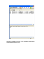
Here is the guide to operate aUSBTerm, step 1 ~ step 3.
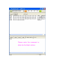
After step 3, it’s available to configure the devices via aUSBTerm. Please enter the
command or data into the blank column.
Please enter the command or
data into the blank column.
Chapter 4 Command Set
Command Set supports user to control NC-980 devices through USB. NC-980 is an
intelligent USBIO device which has multiple IO extended ports as Digital IO, Analog Input,
PWM generator, RS232, RS485, even RF Module. NC-980 can uplink to PC or Host
computer through USB. Most IO pins could be configured by user command.
NC-980 Command Set is a variable-length data block, enable user to configure NC-980
system, control IO Ports, Series Pots, RF functions and Test. Command Data Block is
headed by 0x3e, 0x66, followed with command code, parameters or data. NC-980 may
return result words after command executed. The returned string is headed by “!” , data
headed by other code.
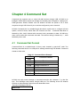
4.1 Command Set Format
Command Block is a variable-length of binary code, headed by code 0x3E, 0x66. The
following command block is an example for sending data through RF Module. Command
Header is fixed code.
Table 5-1: Command Block Example
0x3E
0x66
0x86
0x80
0x0A
0x30
…
…
0x39
Command Header
Command Code
Parameter 1
Length/Parameter 2
Data0
Data 9
NC-980 may reply some message of command execution with character “!” on the first
byte. This message could receive though USB port. The following shows RF Module
receives an Acknowledge Packet from the destination Node.
-Execution Message words as
!ACK OK
4.2 Command List
USBIO series boards can be commanded by the following command set, NC-980 is one
of the USBIO, designed under PC-104 form factor to extend IO for host computer as
Embedded controller or PC through USB connection. PC has OTG or Host USB port.
NC-980 performs an intelligent IO Processor, work independently, commanded by a
binary Command block, which go through USB interface, and IO has DI, DO, PWM,
Analog Input, even Wireless IO.
These IO could be controlled by command block from PC/Host Computer though USB.
The following chapter describes command block individually.
There are two classes of command set, one is usual IO command, another is RF(Wireless)
command set. IO command can also be executed over RF remote control.
4.3 IO Command Description
Each NC-980 Board has different IO pins, 12, 48 or up to 64. Individual IO pin can be
configured by software. IO process can proceed by pin or by port. IO can have Digital
Input, Digital Output, Analog Input and PWM mode (for Servo Control).
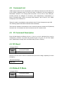
4.3.1IO Reset
-Command Block
0x3E
0x66
0x01
command header
All IO Reset
Set All IO Port low, that is used to command all IO pin at low voltage, especially for some
emergency.
-Execution Message
!All IO=L
4.3.2Default IO Mode
-Command Block
0x3E
0x66
0x02
command header
Default IO Mode
Set All IO Port Low. This is used to command all IO pin at low voltage, especially for some
emergency.
-Execution Message
!Default Set
4.3.3Disable Alarm
-Command Block
0x3E
0x66
0x03
command header
Disable Alarm
Disable Alarm, NC-980 provides alarm function when IO state changed or over/under
Alarm level for ADC voltage, to stop alarm.
-Execution Message
!Disable Alarm
4.3.4Enable Alarm
-Command Block
0x3E
0x66
0x04
command header
Enable Alarm
Enable Alarm, NC-980 will alarm user when IO state changed or over/under Alarm level
for ADC voltage.
-Execution Message
!Enable Alarm
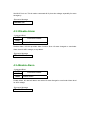
4.3.5Set IO as Digital Input
-Command Block
0x3E
0x66
0x05
0x05
command header
Set Port as Di
Port No, 0..5
Set the Port as Digital Input, IO Port can be configured by Byte or Bit base. If by port, then
8 bits be set as Input together.
-Execution Message
!Set Di Port
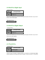
4.3.6Set IO as Digital Output
-Command Block
0x3E
0x66
0x06
0x05
command header
Set Port as Do
Port No, 0..5
Set the Port as Digital Input, IO Port can be configured by Byte or Bit base. If by port, then
8 bits is set as Input together.
-Execution Message
!Set Do Port
4.3.7Test IO Pin
-Command Block
0x3E
0x66
0x09
0x05
command header
Test the IO (pin)
IO No, 0..63
Test the IO (pin). Generate IO flashing ON-OFF for seconds on IO Mode being Digital
Output, Enable user to recognize the DO pin’s location. IO can be not only 0…63, NC-980
series but also supply full or sub set of IO numbers. Please refer to IO model.
If the tested DO pin flashes, it will reset back to original state.
-Execution Message
!IO Testing …
4.3.8Get IO Data
-Command Block
0x3E
0x66
0x0A
command header
Get IO Data
This command is used to get entire IO data from NC-980. USB provides Digital Input,
Digital Output, Analog Input and PWM, etc.
The Data Packet will be packed as below header by 0x3D.
Device ID 0x66.
Status: is alarm flag
0xb0: IO states changed
0xb1: Over up-limit of ADC
0xb2: Below low-limit of ADC
IO Port has 8 bytes, each one has 8 bit, max. 64 IO pins
ADC has 13 channels, 0-11 for 12 channels ADC input, 13th channel is chip temperature.
12 bit resolution each.
Option is 4 words reserved
- After execution, USBIO will send back IO data packet under below format
Mark
ID
Status
IO Port[8B]
ADC[13W]
Option[4W]
EOP
0x3D
0x66
b2/b1/b0
0x55
0x66
B: Byte, as IO Port has 8 Bytes
W: Word, as ADC record has 13 Words.
4.3.9Set IO
-Command Block
0x3E
0x66
0x0B
command header
Set IO:H
0x15
IO No, be 0..63
Set IO pin as High. The mode of this IO should be set Digital Output. Maximum IO pins
can be up to 64 max., from 0 to 63.
Set the Port as Digital Input, IO Port can be configured by Byte or Bit base. If by port, then
8 bits is set as Input together.
-Execution Message
!Set IO
4.3.10
Reset IO
-Command Block
0x3E
0x66
0x0C
0x05
command header
Set IO:L
IO No, 0..63
Set IO pin as Low, The mode of this IO should be set Digital Output. Maximum IO pins can
be up to 64 max, from 0 to 63.
-Execution Message
!Reset IO
4.3.11
Write To Port
-Command Block
0x3E
0x66
0x0D
0x01
0x5A
command header
Write value to Port
Port No, 0..7
Value, 0x00..0xFF
Write a value to the Port. The mode of this IO should be set Digital Output. Maximum
Ports can be up to 7 ports, from 0..7.
-Execution Message
!Put IO Port
4.3.12
Write To Port
-Command Block
0x3E
0x66
0x0D
0x01
0x5A
command header
Write value to Port
Port No, 0..7
Value, 0x00..0xFF
Write a value to the Port. The mode of this IO should be set Digital Output. Maximum Port
can be up to 7 ports, from 0..7.
-Execution Message
!Put IO Port
4.3.13
Set IO Mode
-Command Block
0x3E
0x66
0x0E
0x11
0x02
command header
Set IO Mode
IO No, 0..63
MODE, 0..5
Define IO Mode for IO pin, IO Mode can be configured as
0: Digital Input
1: Digital Output
2: Analog Input
3 & 4: Reserved
5: PWM Generator, Only IO12 may be PWM0
IO13 may be PWM1
IO14 may be PWM2
IO15 may be PWM3
-Execution Message
!Set IO Mode
4.3.14
Set Up Limit for Analog Input
-Command Block
0x3E
0x66
0x0F
0x01
0x10
0x00
command header
Set Up Limit for ADC
ADC channel no,0..11
MSB of Up Limit
LSB of Up Limit
Analog Input is a 12-bit ADC converter. User can define Up Limit value, system will
generate an alarm if analog input value is over Up Limit value, NC-980 will automatically
monitor the reading voltage and compare with the Up-Limit.
-Execution Message
!Set Up Limit
4.3.15
Set Low Limit for Analog Input
-Command Block
0x3E
0x66
0x10
0x01
0x10
0x00
command header
Set Low Limit for ADC
ADC channel no,0..11
MSB of Low Limit
LSB of Low Limit
Analog Input is a 12-bit ADC converter. User can define Low Limit value, system will
generate an alarm when analog input value is lower than Low Limit value, and NC-980
automatically monitor the reading voltage and compare with the Low-Limit.
-Execution Message
!Set Low Limit
4.3.16
Set Default Limit for ADC Alarm
-Command Block
0x3E
0x66
0x11
command header
Set Default Limit for ADC
Set a default Up Limit and Low Limit for each ADC channel.
Up Limit and Low Limit is used for alarm system for ADC, and ADC will alarm host
computer if measured voltage is over or under the set level.
-Execution Message
!Done
4.3.17
Write Parameter into Flash
-Command Block
0x3E
0x66
0x15
command header
Put Parameters into Flash
This command is used to save system parameters into Flash memory.
-Execution Message
!Save to Flash
4.3.18
Read back Parameter from Flash
-Command Block
0x3E
0x66
command header
0x16
Read back Parameters From
Flash
This command is used to read back system parameters from Flash memory.
-Execution Message
!Load from Flash
4.3.19
Send Data to COM1
-Command Block
0x3E
0x66
0x20
0x10
0x30
…
…
0x3F
command header
Send data string to COM1
Length
Data 0
Data 1
Data 15
User could send data string from USB to COM1. COM1 is usually designed as RS232.
Only data string is sent out through COM1. 0x00 is the end of data string.
-Execution Message
NON
4.3.20
Configure COM1 Baud Rate
-Command Block
0x3E
0x66
0x21
0x05
command header
Configure COM1 Baud Rate
Baud Rate No. 0..9
This command is used to set baud rate for COM1, its code from 0~9.
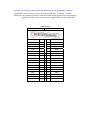
Table: Baud Rate Set for COM1
Code
Baud Rate
0
Auto Baud Rate
1
1200
2
2400
3
4800
4
9600
5
14400
6
19200
7
38400
8
57600
9
115200 (default)
Auto Baud Rate does measure the first input character, if it is carriage return, COM1 will
reset the baud rate automatically. The carriage return is just for recognition, no transmit to
COM1 port.
115200 is a default baud rate.
-Execution Message
!Non
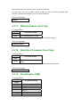
4.3.21
Send Data to COM2
-Command Block
0x3E
0x66
0x22
0x10
command header
Send data string to COM2
Length
0x30
…
…
…
0x3F
Data 0
Data 1
Data 15
User could send data string from USB to COM2. COM2 is usually designed as RS485.
Only data string is sent out through COM2. 0x00 is the end of data string.
-Execution Message
NON
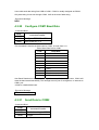
4.3.22
Configure COM2 Baud Rate
-Command Block
0x3E
0x66
0x23
0x05
command header
Configure COM2 Baud Rate
Baud Rate No, 0..9
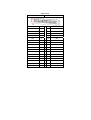
This command is used to set baud rate for COM2, there have code from 0~9.
Table: Baud Rate Set for COM2
Code
Baud Rate
0
Auto Baud Rate
1
1200
2
2400
3
4800
4
9600
5
14400
6
19200
7
38400
8
57600
9
115200 (default)
Auto Baud Rate does measure the first input character, if it is carriage return, COM2 will
reset the baud rate automatically. The carriage return code is just for recognition, no
transmit to COM2 port.
115200 is a default baud rate.
-Execution Message
!Non
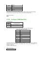
4.3.23
Set PWM Generator
-Command Block
0x3E
0x66
0x36
0x01
0x10
0x00
command header
Set PWM Generator
PWM Ch,0..3
MSB of Positive Pulse tp
LSB of Positive Pulse tp
This command is to set PWM positive pulse width tp, tp must be smaller than tcyc. Tcyc is
entire PWM cycle. Please use the command Configure PWM Generator before use this
command
-Execution Message
!Non
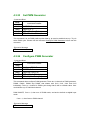
4.3.24
Configure PWM Generator
-Command Block
0x3E
0x66
0x37
0x01
0x01
0x4E
0x20
command header
Configure PWM Generator
PWM Ch,0..3
PWM ON(1)/OFF(0)
MSB of Cyclic Timing tcyc
LSB of Cyclic Timing tcyc
This command does configure PWM generator. There are 4 channels of PWM generator,
PWM0, PWM1, PWM2 and PWM3, that shares with IO12, IO13, IO14 and IO15
individually. The tcyc = 0x4E20 is PWM cyclic timing 20mS, this is a default value. User
could define tcyc for individual channel.
PWM ON/OFF, if set = 0, then turn off PWM mode, set back to default as digital input
mode.
If set = 1, then forms a PWM channel
-Execution Message
!Non
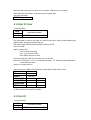
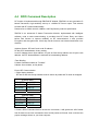
4.4 RFIO Command Description
RF function is implemented through ZBAT2K RF Module. ZBAT2K is a new generation IP
based Transceiver, high sensitivity and up to +20dBm RF Power output. This extends
NC-980 with RF communication ability.
Please refer to USBIO-16I16O, USBISA, and EasySensor products’ specification.
ZBAT2K is an advanced IP based Transceiver Module, implemented with intelligent
software, node to node communicating. It provides Auto RF Power, Retry and Listen
before Talk function to improve reliability on RF communication. It also provides
Encryption and decryption with 128 bit key words to secure user’s data transmission over
wireless.
Address System: RF Net IP and Local IP address.
RF Net IP is fixed address, factory setting.
Local IP Address has 4 Byte address, 2 bytes as Sub Group address and 2 bytes node
address. 0xFFFF Node address is reserved for broadcasting address.
*Term Briefing:
D-Node: Destination Node as “To Node”.
S-Node: Source Node, as “My Node”
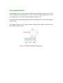
Ensure RF Communication
1. Right Setting Address
RF Net IP and Sub Group Address must be same. My Node and To Node is swapped.
S-Node Addr
RF NETIP
0xA1020304
Sub Group 0xC0A8
My Node
0x0102
To Node
0x0103
D-Node Addr
RF NETIP
0xA1020304
Sub Group 0xC0A8
My Node
0x0103
To Node
0x0102
2. Send a RFIO Command 0x82 to ensure the connection, it will get back a ACK Packet
from D-Node or use 0xA2 command to send a ACK packet to D-Node. User could see the
proper message shown on your host computer.
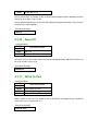
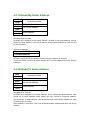
4.4.1S-Node(My Node) Address
0x3E
0x66
0x80
0xC0
0xA8
0x01
0x02
command header
Set My Node Address
Sub-Group Address
Node-Address
Set Address for My Node
0xC0A80102 is assigned as My Node Address. 0xC0A8 is sub-group address, 0x0102
means my Node Address. User should define a unified proper address for each NC-980
by this command.
-Execution Message
MyNode=c0a80102
ToNode=c0a80103
NC-980 will reply the current address setting, the above table is an example.
*You must ensure a proper My Node Address and To Node Address before RF Module
work right.
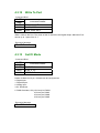
4.4.2D-Node(To Node) Address
0x3E
0x66
0x81
0xC0
0xA8
0x01
0x03
command header
Set To Node Address
Sub-Group Address
Node-Address
Set Address for To Node
0xC0A80103 is assigned as “To Node” Address, this is a destination Node address. User
should set To Node Address before packet sent out; 0xC0A8 is sub-group address,
0x0103 means To Node Address. User should define a unified proper address for each
NC-980 by this command.
Node Address, if set 0xFFFF, then it will be broadcasted to all Node with same sub Group
Address.
-Execution Message
MyNode=c0a80102
ToNode=c0a80103
NC-980 will reply the current address setting, the above table shows an example.
*Must ensure a proper My Node Address and To Node Address before RF Module work
right.
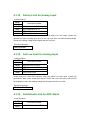
4.4.3Ensure Connection between Nodes
0x3E
0x66
0x82
Command header
Check in Connection
Ensure Connection Between Nodes, S-Node and D-Node.
User could check whether a right connection between Nodes, firstly set individual Node
Address, secondly use this command to check the connection. S-Node sends a
Connection check to D-Node, if D-Node exits, it will reply a ACK packet back to S-Node, at
the same way.
-Execution Message
0xC0
0xA8
0x01
0x02
0x04
0x02
0x76
0xC0
0xA8
D-Node Address
Length
Auto RF Power demand
D-Node Device ID
Option
Option
ACK Node, example as D-Node.
Auto RF Power Demand Flag: A Flag for Auto Adjusted RF Power of sending NC-980.
ACK Node ID: NC-980 Hardware Board ID.
4.4.4Send a Data Packet through RF
-Command Block
0x3E
0x66
0x86
command header
Send a RF Data Packet
0x80
0x0A
0x30
…
…
0x39
Packet type
Packet Length
Data0
Data 9
This command is used to send a data packet to Node B. The maximum data packet is
under 60 bytes per packet.
Please refer to Packet Type definition below, this is important to decide how RF Module
handles this packet. If Packet Type is set 0x80, it means asking for demand D-Node for
sending back a ACK when D-Node receives this data packet. If Packet Type is set 0x40,
showing packet data was encrypted data, it means asking D-Node for decryption after
receiving this data packet. There is build in encryption and decryption algorithm inside RF
Module, user could define 128-bit key by command too.
Individually 0xC0 could ask for ACK back and Encryption at the same time.
The below describes packet header byte for each packet transmission. Example 0x40
shows up an Encrypted data packet.
Packet Header Type
b3-b0 :
0x00: Data Packet
0x01: Voice Packet
0x02: Picture Packet
0x03: NC Command Packet
0x04: Ask Packet
0x05: ACK_OK
0x06: ACK_FAIL
0x07: ACK_RESEND
0x08 - 0x0f:reserved1
b4 : Reserve
b5 : Compressed Packet
b6 : Encrypted Packet
b7 : ACK Request
-Execution Message words
Only when ask for ACK function
!ACK OK
Re-Try and Listen Before Talk
RF Module also provides Re-Try and Listen-before-Talk function to ensure data packet
reachable.
Listen Before Talk function, RF transmission will be delayed for a while if this channel is
occupied, only transmit while channel is clean. RF will report No Free Channel if this
channel is occupied over a long time.
Re-Try function will be implemented only when ask for ACK back, if no ACK back, then
re-send the packet. Continue to Re-Try 16 times. User could ensure it being reachable
when get a reply as “!ACK OK”. Demands a ACK back, by set packet type b7 ON, 0x80.
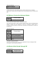
4.4.5Send a Remote IO Control through RF
-Command Block
0x3E
0x66
0x88
0x02
0x0b
0x17
0x00
command header
Remote IO
Remote Command length
Remote Command
Remote Parameter 1
Remote Parameter 2
This is a remote IO Command, User could control D-Node’s IO from S-Node over wireless.
Most IO command set can be implemented as Remote IO. As yellow command block is
transferred to D-Node, D-Node will execute this command as a local command, also
re-send back execution message to S-Node.
Execution message, please refer to individual IO Commands, as above chapter 7.3.
4.4.6Set De/Encryption Key words
-Command Block
0x3E
0x66
0x89
0x10
0x30
…
…
…
0x3F
command header
Send a RF Data Packet
Length of Key Words
Key 0
Key 1
Key 15
User could define key words for De/Encryption. The Key word length is 128 bit. User could
get back the right data only when have the same key words.
4.4.7Nodes Connection Monitor
-Command Block
0x3E
0x66
0x8a
0x01
command header
RF Monitoring
Connection
User could set a connection monitor between S-Node and D-Node, that is S-Node scan
D-Node cyclically, and RF Module will inform host computer “!Disconnection” once
disconnection happens.
No echo back in connecting.
-Execution Message
!Disconnection
If have NO response from D-Node
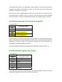
4.4.8Measure and Display RSSI
-Command Block
0x3E
0x66
0x8a
0x02
command header
RF Monitoring
D-Node RSSI Monitoring
User could measure RSSI signal strength from D-Node. When S-Node scans D-Node
cyclically and Trig D-Node to transmit RF signals, RF Module will measure and show the
received RF signal strength.
The replied data packet includes some message as
D-Node Address
RSSI measurement value and its real dBm value that received by S-Node.
-Execution Message
0xC0 0xA8 0x01 0x02 0x97
D-Node
RSSI
RSSI=-65dBm
RSSI in dBm
The scanning for each measurement is around 1 sec. User could get actual RSSI
measurement by dBm.
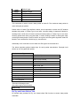
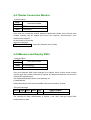
4.4.9WhoOnSky
-Command Block
0x3E
0x66
0x90
command header
WhoOnSky
S-Node issues a broadcasting packet to all who is on sky, and each Node will individually
send back ACK packet with some information as below.
Each response Node does randomly generate a delay, then transmit back to S-Node.
S-Node will send back to host computer, might record into database as a WhoOnSky List.
Any Node with same RF Net IP address and same Sub Group Address that will
automatically response this broadcasting.
-Replied Message
0xC0
0xA8
0x01
0x02
0x04
0x02
0x76
0xC0
0xA8
D-Node IP Address
Length
Auto RF Power demand
D-Node Device ID
Option
Option
Auto RF Power
RF Module will automatically tune RF power by get ACK Packet. S-Node will increase or
decrease RF Power according to receiving signal strength from D-Node.
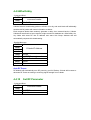
4.4.10
Set RF Parameter
-Command Block
0x3E
0x66
0x92
0x06
command header
Set RF Parameter
Mode No
4.4.11
Shutdown RF Module
-Command Block
0x3E
0x66
0x93
command header
Shutdown RF Module
This command is used to shutdown RF Module. It will have a few uA power dissipation
only. No RF functions at all after this command.
-Execution Message
!RF Module:OFF
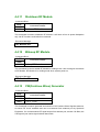
4.4.12
Wakeup RF Module
-Command Block
0x3E
0x66
0x94
command header
Wakeup RF Module
This command is used to enable RF Module in working mode. User could give commands
to RF Module. RF Module is in working mode when system power on.
-Execution Message
!RF Module:ON
4.4.13
CW(Continue Wave) Generator
-Command Block
0x3E
0x66
0x95
0x01
command header
CW Generator
0: OFF, 1:ON
This Command is used to generate and transmit a CW Continue Wave Signal at antenna,
to ensure RF circuit workable and can be measured from antenna port by Spectrum
Equipment. You could measure RF signal output from antenna port, around +20 dBm, this
CW signal is just carrier signal without data inside.
-Execution Message when turn on CW Generator
!CW Generator=ON
-Execution Message when turn off CW Generator
!CW Generator=OFF
4.4.14
Test Command: Quick Set Node Address
-Command Block
0x3E
0x66
0xA0
0x01
command header
Test:Set Fixed Node Address
0: Add-A, 1:Add-B
For Quick Test purpose, quickly assign a default Node Address.
When parameter is 0,
-Execution Message as
MyNode=c0a80102
ToNode=c0a80103
When parameter is 1,
-Execution Message as
MyNode=c0a80103
ToNode=c0a80102
4.4.15
Test Comand: Display All Node Address
-Command Block
0x3E
0x66
0xA1
command header
Display All Node Address
This command is getting all Node address setting from RF Module, RF Net Address, My
Node Address, To Node Address and Receive Address.
-Execution Message
Display all Node IP Address as
0xA1020304
0xC0A80102
0xC0A80103
0xC0A8FFFF
RF Net IP Address
My Node Address
To Node Address
Received "To Addr"
4.4.16
Test Command: Send Out a ACK Packet
-Command Block
0x3E
0x66
command header
0xA2
RF Transmit out a ACK
Packet
This command is to send out a ACK packet to D-Node, to identify a transmission
workable.
-Execution Message
D-Node will display “!ACK OK” if succeed receiving this ACK Packet.
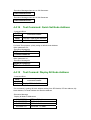
4.4.17
Test Command: Encryption and Decryption
-Command Block
0x3E
0x66
0x89
0x0A
0x30
…
…
…
0x39
command header
En/Decryption Show up
Length of Data
Data 0
Data 9
This test command is to identify encryption and decryption function. En/decryption
software module is built in, so user could set 128 bit keywords for en/decryption by
another command.
User could input a proper string, string length under 60 Bytes.
-Execution Message after encryption
0xC9 0xAE 0x16 …………………….0x22
Encrypted
Then recover back to original string
-Execution Message after decryption
0x30 0x31 0x32 ………………………0x39
Decrypted
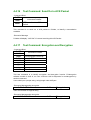
4.4.18
Test Command: Erase Parameters from Flash
-Command Block
0x3E
0x66
0xA6
command header
Erase Para Flash
This command is used to erase all system parameters from Flash Memory.
-Execution Message
!Para Flash Erased
Chapter 5 Programming
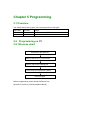
5.1 Overview
The USBIO device has 2 pipes, one read pipe and one write pipe.
Pipe index
Pipe des
Usage
0
Read pipe 1
Read data from USBIO device
1
Write pipe 1
Write data to USBIO device
5.2 Programming on PC
5.2.1Process chart
Enumerate USB Devices
Select a USB Device for communication
Open a pipe of the USB Device
communicate by this pipe(Read or Write)
Close this pipe
Before programming, please install USB driver first
(NcUsb.inf, NcUsb.sy, WdfCoInstaller01009.dll)
5.2.2API Summary (Windows operation system)
API
Description
SetupDiGetClassDevs
Enumerate aUSBIO ISA64 devices
SetupDiEnumDeviceInterfaces
SetupDiGetDeviceInterfaceDetail
CreateFile
Open a pipe of the aUSBIO ISA64 device
ReadFile
Reads data from the pipe of the aUSBIO ISA64 device
WriteFile
Writes data to the pipe of the aUSBIO ISA64 device
CloseFile
Close the pipe of the aUSBIO ISA64 device
5.2.3Example
5.2.3.1 Enumerate all USBIO series devices
z Get the GUID interface of the USB device
DEFINE_GUID(GUID_DEVINTERFACE_LFUSB,
0xa5dcbf10, 0x6530, 0x11d2, 0x90, 0x1f, 0x00, 0xc0, 0x4f, 0xb9, 0x51, 0xed);
z Find all devices that identify by the GUID interface
DWORD
lastError;
LONG
ii = 0;
HDEVINFO
hDeviceInfo;
DWORD
bufferSize;
SP_DEVICE_INTERFACE_DATA
PSP_DEVICE_INTERFACE_DETAIL_DATA
interfaceData;
deviceDetail;
// Find all devices that have our interface
hDeviceInfo = SetupDiGetClassDevs(
(LPGUID)&GUID_DEVINTERFACE_LFUSB,
NULL,
NULL,
DIGCF_PRESENT | DIGCF_DEVICEINTERFACE
);
if (hDeviceInfo == INVALID_HANDLE_VALUE)
{
lastError = GetLastError();
AfxMessageBox(_T("SetupDiGetClassDevs failed, GetLastError() = %d"), lastError);
return lastError;
}
// Setup the interface data struct
interfaceData.cbSize = sizeof(SP_DEVICE_INTERFACE_DATA);
for (ii = 0;
SetupDiEnumDeviceInterfaces(
hDeviceInfo,
NULL,
(LPGUID)&GUID_DEVINTERFACE_LFUSB,
ii,
&interfaceData);
++ii)
{
// Found our device instance
if (!SetupDiGetDeviceInterfaceDetail(
hDeviceInfo,
&interfaceData,
NULL,
0,
&bufferSize,
NULL))
{
if (GetLastError() != ERROR_INSUFFICIENT_BUFFER)
{
AfxMessageBox(_T("Error: couldn't get interface detail, (%d)"), GetLastError());
continue;
}
}
// Allocate a big enough buffer to get detail data
deviceDetail = (PSP_DEVICE_INTERFACE_DETAIL_DATA)malloc(bufferSize);
if (deviceDetail == NULL)
{
AfxMessageBox(_T("Error: Buffer allocation failed"));
continue;
}
// Setup the device interface struct
deviceDetail->cbSize = sizeof(SP_DEVICE_INTERFACE_DETAIL_DATA);
// Try again to get the device interface detail info
if (!SetupDiGetDeviceInterfaceDetail(
hDeviceInfo,
&interfaceData,
deviceDetail,
bufferSize,
NULL,
NULL))
{
free(deviceDetail);
continue;
}
m_strDeviceName[m_nDeviceNum]=deviceDetail->DevicePath;
m_nDeviceNum++;
// Free our allocated buffer
//usb
free(deviceDetail);
}
SetupDiDestroyDeviceInfoList(hDeviceInfo);
5.2.3.2 Select an USBIO series Device
CString m_strMasterNodeUSBName;
for(int i=0;i< m_nDeviceNum;i++)
{
if(strstr(m_strDeviceName[i],"vid_0471&pid_0999"))
{
m_strMasterNodeUSBName = m_strDeviceName[i];
return TRUE;
}
}
5.2.3.3 Open USB Pipes
The USBIO device has 2 pipes, one write pipe and two read pipes.
IN pipe index: 0
OUT pipe index: 1
CString strPipe;
HANDLE
m_hReadPipe, m_hWritePipe;
(1)Open read pipe
strPipe.Format("%s\\PIPE%02d", m_strMasterNodeUSBName,0);
m_hReadPipe = CreateFile(
strPipe,
GENERIC_READ | GENERIC_WRITE,
FILE_SHARE_READ | FILE_SHARE_WRITE,
NULL,
OPEN_EXISTING,
NULL,
0
);
(2)Open write pipe
strPipe.Format("%s\\PIPE%02d", m_strMasterNodeUSBName,1);
m_hWritePipe = CreateFile(
strPipe,
GENERIC_READ | GENERIC_WRITE,
FILE_SHARE_READ | FILE_SHARE_WRITE,
NULL,
OPEN_EXISTING,
NULL,
0
);
5.2.3.4 Reads Data from Read Pipe
UINT RecvThread(LPVOID pParam)
{
do
{
if(ReadFile(m_hReadPipe,lpBuffer,nNumberOfBytesToRead,&nNumberOfBytesRead,NULL))
{
……
}
else if(m_bRecv)
{
Sleep(50);
}
}while(m_bRecv);
return 0;
}
5.2.3.5 Write Data to Write Pipe
BYTE* lpBuffer;
DWORD nNumberOfBytesToWrite, nNumberOfBytesWritten;
WriteFile(m_hWritePipe,lpBuffer,nNumberOfBytesToWrite,& nNumberOfBytesWritten,NULL);
5.2.3.6 Close USB Pipes
(1)Close read pipe
If you open a thread for the read pipe, please close it first
if(m_hReadPipe!= INVALID_HANDLE_VALUE)
{
CloseHandle(m_hReadPipe);
m_hReadPipe = INVALID_HANDLE_VALUE;
}
(2)close write pipe
if(m_hWritePipe!= INVALID_HANDLE_VALUE)
{
CloseHandle(m_hWritePipe);
m_hWritePipe = INVALID_HANDLE_VALUE;
}
5.2 USB Programming on WinCE
5.2.1Process chart
Open a USBIO Device
communicate with this pipe(Read or Write)
Close Device
Before programming please install USB driver first (NcUsb.dll)
5.2.2API Summary (WinCE system)
Table 1:
API
Description
CreateFile
Open an USBIO ISA64 device
CloseHandle
Close the a USBIO ISA64 device
DeviceIoControl--
Reads data from the read pipe of the USBIO ISA64 device
IOCTL_NCD_READ_PIPE1
DeviceIoControl-IOCTL_NCD_WRITE_PIPE1
Writes data to the write pipe of the USBIO ISA64 device
5.2.3Example
///////////////////////////////////////////////////////////////////////////////////////////////////////////////////////////
#define IOCTL_NCD_READ_PIPE1
\
CTL_CODE(IOCTL_NC_BASE, 0x1002, METHOD_BUFFERED, FILE_ANY_ACCESS)
#define IOCTL_NCD_WRITE_PIPE1
\
CTL_CODE(IOCTL_NC_BASE, 0x1004, METHOD_BUFFERED, FILE_ANY_ACCESS)
///////////////////////////////////////////////////////////////////////////////////////////////////////////////////////////////
HANDLE hUSBIO = NULL;
//run thread
Void StartRecv()
{
bRecv=TRUE;
if(pRecvThread==NULL)
{
pRecvThread =
AfxBeginThread(RecvThread,this,THREAD_PRIORITY_HIGHEST,0,CREATE_SUSPENDED,NULL);
pRecvThread->m_bAutoDelete=FALSE;
pRecvThread->ResumeThread();
}
}
//stop thread
BOOL StopRecv()
{
int inTry=0;
nReTryTimes=0;
bRecv = FALSE;
if(pRecvThread == NULL)
return TRUE;
bRecv=FALSE;
if(WaitForSingleObject(pRecvThread->m_hThread,2000)==WAIT_OBJECT_0)
{
delete pRecvThread;
pRecvThread=NULL;
pRecvCWnd=NULL;
return TRUE;
}
return FALSE;
}
5.2.3.1 Open an aUSBIO ISA64 Device
Remarks: strDevName=“NCD1:”//USBIO device name
BOOL OpenDevice()
{
Close();
hUSBIO = CreateFile(
“NCD1:”,
GENERIC_READ | GENERIC_WRITE,
FILE_SHARE_READ | FILE_SHARE_WRITE,
NULL,
OPEN_EXISTING,
NULL,
0
);
if(hUSBIO != INVALID_HANDLE_VALUE)
{
StartRecv();
return TRUE;
}
return FALSE;
}
5.2.3.2 Reads Data from the Read Pipe
UINT RecvThread(LPVOID pParam)
{
DWORD dwInDataLen;
BYTE byInData[64];
do
{
if( DeviceIoControl(hUSBIO,IOCTL_NCD_READ_PIPE1,NULL,NULL,byInData,PIPE_BUFFER_S
IZE,&dwInDataLen,NULL))
{
……
}
else if(bRecv)
{
Sleep(50);
}
return 0;
}while(bRecv);
}
5.2.3.3 Write Data to Write Pipe
DWORD dwOutDataLen;
BYTE byOutData[64];//NC command,for example:”NC?DOA”
if(DeviceIoControl(hUSBIO,IOCTL_NCD_WRITE_PIPE1,byOutData,PIPE_BUFFER_SIZE,NULL,NULL
,&dwOutDataLen,NULL))
{
……
}
5.2.3.4 Close the aUSBIO ISA64 Device
BOOL CloseDevie()
{
if(hUSBIO == INVALID_HANDLE_VALUE)
return TRUE;
if(StopRecv())
{
CloseHandle(hUSBIO);
hUSBIO
}
return TRUE;
}
= INVALID_HANDLE_VALUE;