1
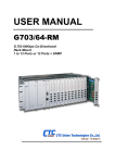
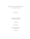
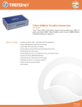
FRM220A
Hardware Installation
CTC Union Technologies Co., Ltd.
Far Eastern Vienna Technology Center (Neihu Technology Park)
8F, No. 60 Zhouzi St.
Neihu District
Taipei 114
Taiwan
Tel:
+886-2-26591021
Fax:
+886-2-27991355
Email: [email protected]
URL: http://www.ctcu.com
FRM220A Hardware Installation Manual
Fiber In-band Managed
Media Platform Rack, 20 Slot, 2U with GbE Aggregate Switch
Version 0.9d May 2011 (pre-Release)
Copyright © 2007~2011, CTC Union Technologies, Inc.
All rights reserved.
All specifications are subject to change without prior notice.
Legal
The information in this publication has been carefully checked and is believed to be entirely accurate at the time of publication.
CTC Union Technologies assumes no responsibility, however, for possible errors or omissions, or for any consequences
resulting from the use of the information contained herein. CTC Union Technologies reserves the right to make changes in its
products or product specifications with the intent to improve function or design at any time and without notice and is not
required to update this documentation to reflect such changes.
CTC Union Technologies makes no warranty, representation, or guarantee regarding the suitability of its products for any
particular purpose, nor does CTC Union assume any liability arising out of the application or use of any product and
specifically disclaims any and all liability, including without limitation any consequential or incidental damages.
CTC Union products are not designed, intended, or authorized for use in systems or applications intended to support or sustain
life, or for any other application in which the failure of the product could create a situation where personal injury or death may
occur. Should the Buyer purchase or use a CTC Union product for any such unintended or unauthorized application, the Buyer
shall indemnify and hold CTC Union Technologies and its officers, employees, subsidiaries, affiliates, and distributors
harmless against all claims, costs, damages, expenses, and reasonable attorney fees arising out of, either directly or indirectly,
any claim of personal injury or death that may be associated with such unintended or unauthorized use, even if such claim
alleges that CTC Union Technologies was negligent regarding the design or manufacture of said product.
TRADEMARKS
Microsoft is a registered trademark of Microsoft Corp.
HyperTerminal™ is a registered trademark of Hilgraeve Inc.
WARNING:
This equipment has been tested and found to comply with the limits for a Class A digital device, pursuant to Part 15 of the
FCC Rules. These limits are designed to provide reasonable protection against harmful interference when the equipment is
operated in a commercial environment. This equipment generates, uses, and can radiate radio frequency energy and if not
installed and used in accordance with the instruction manual may cause harmful interference in which case the user will be
required to correct the interference at his own expense. NOTICE: (1) The changes or modifications not expressively approved
by the party responsible for compliance could void the user's authority to operate the equipment. (2) Shielded interface cables
and AC power cord, if any, must be used in order to comply with the emission limits.
CISPR PUB.22 Class A COMPLIANCE:
This device complies with EMC directive of the European Community and meets or exceeds the following technical standard.
EN 55022 - Limits and Methods of Measurement of Radio Interference Characteristics of Information Technology Equipment.
This device complies with CISPR Class A.
CE NOTICE
Marking by the symbol CE indicates compliance of this equipment to the EMC and LVD directives of the European
Community. Such marking is indicative that this equipment meets or exceeds the following technical standards: EN
55022:2006, Class A, EN55024:1998+A1:2001+A2:2003, and EN60950-1:2001
Table of Contents
Chapter 1 Introduction.................................................................................................................................................................. 7 1.0 Introduction.......................................................................................................................................................................... 7 1.1 Functional Description ......................................................................................................................................................... 7 1.2 Chassis Front Description .................................................................................................................................................... 8 1.3 Chassis Rear Description ..................................................................................................................................................... 8 1.4 Chassis Physical Dimensions ............................................................................................................................................... 9 1.5 Chassis Specifications........................................................................................................................................................ 10 1.6 GSW/SNMP (Aggregate Switch)....................................................................................................................................... 10 1.7 FRM220-1000EAS/X 802.3ah In-band managed Gigabit Fiber Media Converter............................................................ 11 1.8 FRM220A-E1/ET100 E1 Inverse Multiplexer (Ethernet over E1) .................................................................................... 12 1.9 FRM220A-EoE1 Ethernet Bridge (Ethernet over E1) ...................................................................................................... 13 1.10 FRM220A-E1/Data Fractional E1 DSU/CSU Card ......................................................................................................... 14 Chapter 2 Installation.................................................................................................................................................................. 15 2.1 Introduction....................................................................................................................................................................... 15 2.2 Site Preparation ................................................................................................................................................................. 15 2.3 Mechanical Assembly ....................................................................................................................................................... 15 2.3.1 Rack mounting............................................................................................................................................................. 15 2.3.2 Fan Units Removal/Replacement ................................................................................................................................ 16 2.3.3 Line Card Conversion, Stand-alone/Rack ................................................................................................................... 16 2.4 Electrical Installation ........................................................................................................................................................ 17 2.5 Alarm Installation.............................................................................................................................................................. 17 2.6 Power Modules Removal/Replacement ............................................................................................................................ 18 2.7 Installation......................................................................................................................................................................... 19 2.7.1 Line Card Installation .................................................................................................................................................. 19 2.7.2 GSW/SNMP Card Installation..................................................................................................................................... 19 Chapter 3. Management Quick Start............................................................................................................................................ 21 3.1 Introduction........................................................................................................................................................................ 21 3.2 Management Methods........................................................................................................................................................ 21 3.3 Web based Management .................................................................................................................................................... 21 3.3.1 Default IP settings ....................................................................................................................................................... 21 3.4 Web Based Manager .......................................................................................................................................................... 22 3.5 Element Management System (EMS) ................................................................................................................................ 23 i
Table of Contents
ii
Chapter 1 Introduction
Chapter 1 Introduction
1.0 Introduction
Thank you for choosing FRM220A Platform Fiber Media Converter Rack. If you would like to skip right to the
installation of the Converter Chassis, proceed to Chapters 2.
This manual is used to explain the hardware installation procedures for FRM220A, and present its capabilities
and specifications. This manual is divided into 2 Sections, the Introduction and Installation, plus the Appendix. The
Appendix includes further information on options for placing the device in service.
Installers should carefully read the Chapter 2, Installation and the Cabling Specification Appendix. The
companion document, the FRM220A GSW/SNMP Configuration Manual, is available in electronic format only.
The divisions in that manual are intended for use by personnel to answer questions in general areas. Planners and
potential purchasers may read the Introduction to determine the suitability of the product to its intended use;
Operating Personnel would use the Operations and Web Based Management Chapters and Appendices to
become familiar with the line cards and settings. Network Administrators should read the chapters on Operation,
Web Based Management and Trouble Shooting to become familiar with the diagnostic capabilities, network
settings and management strategies for the SNMP managed chassis.
1.1 Functional Description
FRM220A-CH20 is a 2U high 19" Rack, 20 slot modular media converter center with an integral 24+4 Gigabit
Ethernet aggregate L2 switch backplane. FRM220A provides a modular solution for FTTx by combining L2
switching and media conversion in one manageable platform. All critical components, Power, fans, management
module, L2 switch and interface cards are hot swappable allowing online field replacement. An additional feature
allows FRM220A to detect the working or failing status either of power module or any fan assembly in the unit and
activate relays that can be used to control external alarm devices.
There are 20 slots available for installation of FRM220A Converter Cards in the FRM220A rack. The L2 Gigabit
Switch/SNMP Card is installed through the rear of the CH20 chassis. Each of 20 slots may connect to the integral
Gigabit switch through individual 10/100/1000 interfaces to the backplane. Each FRM Card may be an independent
fiber to copper converter or can connect to the aggregate switching backplane. When linked at the far end to a
compatible FRM stand-alone or "I" series FMC (Fiber Media Converter) stand-alone converter, complete in-band
management is supported. All settings of the line card and remote connected stand-alone device may be managed
through any of the available management interfaces. A variety of cards are or will be available that support multimode or single-mode fiber types and connections to SC, ST, FC or even the latest bi-directional single fiber WDM
(Wave Division Multiplexing) in ranges from 2Km to 120Km. Converter cards will include Fast Ethernet, Gigabit
Ethernet, Inverse Multiplexer cards in 1, 5, 8, or 16E1 and more as the product matures.
FRM220A incorporates redundant power modules, when two supplies are installed The supplies, depending on
the model, derive power from either an AC power source (100 ~ 240VAC) and/or DC power source. Two available
DC power modules provide either 18-36VDC or 36-72VDC range. When two modules are installed, they provide for
power redundancy and are hot swappable even during FRM220A Line Cards' transmissions. FRM220A provides
all copper interface connections on the face of each Line Card. The fiber interface connectors are also located on
the individual Line Card's face, along with status indicator LEDs. The status LED indicators provide for quick
indications of both copper and fiber link statuses and fault detection.
The FRM220A-CH20 incorporates a Layer 2 Gigabit Ethernet access switch that provides 1GbE to each of the
20 card slots for Ethernet Aggregation.
4xGbE SFP
4xGbE UTP
24+4
access switch
20 slots
1 to 20 FRM220A Line Cards
FRM220A Simple Block Diagram
7
Chapter 1 Introduction
1.2 Chassis Front Description
The front of FRM220A contains the line card slots. They are numbered 1 through 20, from left to right as
viewed from the front. The typical configuration is with one GSW/SNMP (Network Management Controller) card
in rear slot and in-band manageable line cards in any front slot numbered 1 through 20.
FRM220A Series In-Band Managed
Line Cards
Figure 1-1 Chassis Front View
1.3 Chassis Rear Description
The rear panel holds the aggregate switch card, the hot-swappable cooling fan modules, and the hotswappable power modules. The pluggable modules do not require any tools for removal and replacement.
Cooling Fan
Power Module 1
AC Type Shown
Alarm Relay
Contacts
Gigabit Aggregate Switch
Terminal Strip
for DC Power
IEC AC Mains Input
Figure 1-2 Chassis Rear View
8
Cooling Fan
Power Module 2
DC Type Shown
Chapter 1 Introduction
1.4 Chassis Physical Dimensions
Figure 1-3 Chassis Dimensions, in millimeters
9
Chapter 1 Introduction
1.5 Chassis Specifications
Environment
Temperature
Humidity
-10 - 50°C (14-122°F)
5-95% non condensing
Alarm relay contact ratings
125VAC
1A
110VDC
0.6A
30VDC
4A
Power Module Specifications
AC Power Module
Input : Universal, 100~240VAC ±10% at ambient temperature; Frequency : 47~63 Hz
Output : DC 12V, 200W maximum rating (Green power rated, 89% power efficiency)
DC Power Module
Input : -36~75 VDC (option 1)
Input : -18~-36VDC (option 2)
Output : DC 12V, 200W maximum rating
Power Consumption
~120 watts (fully loaded chassis, with random mix of line card types)
Heat Generation
~280 BTU (fully loaded chassis, with random mix of line card types)
Compliance
European Union : EN55022:2006, Class A, EN55024:1998+A1:2001+A2:2003, and EN60950-1:2001
FCC : part 15, subpart B, class A
Reliability
MTTB : >65,000 hours (25°C)
Physical Specifications
Dimensions : 438mm (Width) x 302mm (Depth) x 88mm (Height)
(US: 17 1/4" wide x 11 7/8" deep x 3 1/2" high)
Weight : 4.5Kg (US: ~10 lbs)
AC module weight : 690g (US 1.5 lbs)
DC module weight : 505g (US 1.2 lbs)
Fan module weight : 200g (US 0.5 lbs)
GSW/SNMP card weight : 200g (US 0.25 lbs)
Net Weight : 7.0kgs (US 15 lbs 8 oz)
(with 1 GSW/SNMP, 2 fan modules, 1 AC +1 DC power module & two bracket panels for 19" rackmounting)
Fully Populated Reference Net Weight: 8.7Kg (US 19.2 lbs.)
(fully loaded, two powers, GSW/SNMP and 20 pcs 5E/ET100 line cards)
1.6 GSW/SNMP (Aggregate Switch)
FRM220A must be ordered with an aggregate Card. The card is placed in the rear of the chassis and provides
backplane connection to each card slot. Management is accomplished either via Ethernet and any standard SNMP
network management software that supports MIB-II. The WEB GUI based interface provides an easy method for
the user to operate and monitor the whole system. Almost all FRM line cards support remote in-band configuration
when paired with the same type FRM220A stand-alone in-band converter.
10
Chapter 1 Introduction
1.7 FRM220-1000EAS/X 802.3ah In-band managed Gigabit Fiber Media Converter
This IEEE802.3ah OAM compliant copper to fiber Gigabit Ethernet solution is designed to make conversion
between 10/100/1000Base-TX and 1000Base-SX/LX with SFP-LC connector. With SNMP agent and GUI Webbased management in FRM220A, the Network administrator can monitor, configure and control the activity of each
802.3ah series line card. This 802.3ah OAM Compliant media converter, with its Q-in-Q and maximum
interoperability will enable carriers and service provider to have a clear vision of their network and conveniently
manage their demarcation point.
Features
• 802.3ah In-band OAM management compliant
• 2 ports 10/100/1000Base-T and 2 ports GbE fiber (SFP)
• Supports Flow control function
• Supports OAM remote loopback
• Supports rapid spanning tree function
• Supports bandwidth control
• Link Fault Pass-thru
• Transparent Link Loss Forwarding
• Supports Dying Gasp Reporting for power outage
• Supports local / remote monitor
• Supports local / remote Configuration
• Supports Q in Q double tagged frame transparent
• Supports Ethernet frame sizes up to 9K bytes
• Supports remote F/W upgrade (In-band)
• Supports IEEE 802.1q Tag VLAN pass thru and port-base VLAN
• Provides fiber transceiver information for management
• Compatible with FRM220A Managed Chassis
Fiber SFP
(LC Type)
LED
Indicators
10/100/1000
Ethernet
LAN Interface Specification
Two RJ-45 female connectors for straight or cross-over connection.
Supports 2-port 10/100/1000Base, n-way (Auto-Negotiation).
1000EAS is a stand-alone
Supports Full, Half duplex, 10/100/1000 speed force mode selections.
manageable 4 port Gigabit Ethernet
Transmission Packet Rate for 10Base-T: 14880 per second
fiber switch, utilizing SFP for
100Base-TX: 148800 per second ; 1000Base-T: 1488000 per second
1000Base-SX/LX fiber connection
Copper TP cable 4 pair Cat. 5e or 6 UTP
and two 10/100/1000 Ethernet
Optical Interface Specification
electrical ports.
Transceiver Connector type:SFP-LC
Supports 2-port, 1000Mbps SFP slot
Supports auto-receive sensitivity function, no extra attenuators needed.
General Specification
Standards IEEE 802.3 10Base-T,
IEEE 802.3u 100Base-TX , 100Base-FX,
IEEE 802.3ab, 802.3z 1000Base-T, 1000Base-SX/LX
IEEE 802.3ah In-band OAM management compliant
6 diagnostic LEDs : Power / FX-Link ,TX-Speed / TX-Duplex/ TX-Link / Test (loopback)
Temperature: -10 - 60° C (Operating);-20 - 70° C (Storage).
Humidity: 0-95% non-condensing (Operating); 10-90% (Storage).
Power: DC Jack : Switching adaptor (12V, 1A)
Consumption: < 12W
Dimensions: 155mm x 88mm x 23mm (LxWxH).
Weight: 140g.
Compliance: FCC part 15, Subpart B, Class A,
ANSI C63.4:2003
CE EN55022:2006, Class A
EN55024:1998+A1:2001+A2:2003
LVD: EN60950-1:2001
MTBF: 65,000 h (25°C)
This product includes the following models:
• 1000EAS/X (2 electrical plus 2 SFP)
11
Chapter 1 Introduction
1.8 FRM220A-E1/ET100 E1 Inverse Multiplexer (Ethernet over E1)
The FRM220A-E1/ET100, 5E1/ET100, 8E1/ET100 and 16E1/ET100 are 1, 5, 8, or 16 E1 inverse multiplexer
cards capable of bundling up to 16 E1 lines for cost-effective connection of 10/100BaseTX or 100Base-FX LANs
over multiple E1 transports. The FRM220A-16E1/ET100 inverse multiplexer transmits up to a 31.74Mbps Ethernet
bridge channel (GFP-F encapsulated) over 16 E1 links. The FRM220A-16E1/ET100 bridges the gap between E1
and E3, allowing bridges to operate at faster rates. It also provides high speed access to SDH/SONET backbones
where the only access services available are E1 lines. The FRM220A-16E1/ET100 supports an E1 attenuation of
up to 43 dB on twisted pair or coax cable. This provides an approximate operating range up to 2km (using 22AWG).
The FRM220A-16E1/ET100 fully meets E1 specifications including ITU-T G.703 and G.823. The FRM220A16E1/ET100 features diagnostic capabilities for performing remote loopback. The operator at either end of the line
may test both the FRM220A-16E1/ET100 and the line in the digital loopback mode. The Ethernet copper interface
supports auto-negotiation and auto MDI/MDIX, allowing plug-and-play Ethernet connection without any additional
configuration.
Features
• Connects one Fast Ethernet over up to16E1 links (1.984Mbps to 31.74Mbps)
• Built-in GFP-F bridge operates at WAN rate
• Auto-Negotiation
• Maximum 220ms delay variance tolerable between E1 links
• Unbalanced E1/BNC or balanced E1/RJ45
• Fully compatible with FRM220A-CH20 chassis
Supports backplane or front panel connection of Ethernet
• SNMP management with FRM220A-GSW/SNMP
• LED Alarm indication
Specifications
Ports
E1
Framing
Standards
Bit Rate
Line Code
Clock Set
Rx Level
Impedance
Jitter Spec
Pulse Mask
Pulse Amplitude
Delay Variance
Diagnostics
Ethernet
Standards
Interface
Cable type
SFP type
Cable type
LEDs
Power
Consumption
Dimensions
Weight
Temperature
Humidity
Certification
MTBF
CCS+CRC4
ITU-T G.703/ G.704/ G.732/ G.823 Recommendations
2.048Mbps ±50ppm (1, 5, 8, or 16E1)
HDB3
Internal Oscillator or Recovery clock
-43dBm sensitivity (XLH)
RJ45 E1-120ohm, BNC E1-75ohm
ITU-T G.823 recommendations
G.703 Recommendations
2.37V ±10% Nominal
up to 220ms between E1 paths in bundle
Remote Digital Loopback
802.3, 802.3u
10/100Base-TX, Half/Full Duplex
Cat5, 5e, 6
LC 100Base-FX
Multi-mode (62.2/125um), Single mode (9/125um)
Power, Alarm, E1 Signal loss, E1 Alarm (AIS, LOF, RAI, LOMF)
LAN Lnk/Act, 10/100M, SD (100Base-FX)
DC In 12V
< 12W
155 x 88 x 23mm (D x W x H)mm
120g
-10~60°C (Operating) ,-20~70°C (Storage)
10~95% non-condensing
CE, FCC, LVD, RoHS
65,000 h (25°C)
This product includes the following models:
• FRM220A-E1/ET100T (Single E1 Ethernet Bridge RJ-45), FRM220A-E1/ET100S (Single E1 Ethernet Bridge SFP)
• FRM220A-5E1/ET100T (5xE1 Inverse Multiplexer RJ-45), FRM220A-5E1/ET100S (5xE1 Inverse Multiplexer SFP)
• FRM220A-8E1/ET100T (8xE1 Inverse Multiplexer RJ-45), FRM220A-8E1/ET100S (8xE1 Inverse Multiplexer SFP)
• FRM220A-16E1/ET100T (16xE1 Inverse Multiplexer RJ-45), FRM220A-16E1/ET100S (16xE1 Inverse Multiplexer SFP)
12
Chapter 1 Introduction
1.9 FRM220A-EoE1 Ethernet Bridge (Ethernet over E1)
The FRM220A-EoE1 is a single E1 Ethernet bridge card capable of carrying 10/100BaseTX or 100Base-FX
LANs over single E1 transports. The FRM220A-EoE1 transmits up to a 1.8Mbps Ethernet bridge channel (HDLC
encapsulated) over 1 E1 link. The FRM220A-EoE1 supports an E1 attenuation of up to 43 dB on twisted pair or
coax cable. This provides an approximate operating range up to 2km (using 22AWG). The FRM220A-EoE1 fully
meets E1 specifications including ITU-T G.703 and G.823. The FRM220A- EoE1 features diagnostic capabilities for
performing remote loopback. The operator at either end of the line may test both the FRM220A- EoE1 and the line
in the digital loopback mode. The Ethernet copper interface supports auto-negotiation and auto MDI/MDIX, allowing
plug-and-play Ethernet connection without any additional configuration.
Features
• Connects one Fast Ethernet over 1 E1 link
• Built-in HDLC bridge operates at WAN rate
• Unframed or Fractional E1 supported
• LAN port with Auto-Negotiation
• Unbalanced E1/BNC or balanced E1/RJ45
• Fully compatible with FRM220A-CH20 chassis
Supports backplane or front panel connection of Ethernet
• SNMP management with FRM220A-GSW/SNMP
• LED Alarm indication
Specifications
Ports
E1
Framing
Standards
Bit Rate
Line Code
Clock Set
Rx Level
Impedance
Jitter Spec
Pulse Mask
Pulse Amplitude
Diagnostics
Unframed or CCS
ITU-T G.703/ G.704/ G.732/ G.823 Recommendations
2.048Mbps ±50ppm (internal Osc)
HDB3
Internal Oscillator or Recovery clock
-43dBm sensitivity (XLH)
RJ45 E1-120ohm, BNC E1-75ohm
ITU-T G.823 recommendations
G.703 Recommendations
2.37V ±10% Nominal@75Ω
3.00V ±10% Nominal@120Ω
Remote Digital Loopback
Ethernet
Standards
Interface
Cable type
SFP type
Cable type
LEDs
Power
Consumption
Dimensions
Weight
Temperature
Humidity
Certification
MTBF
802.3, 802.3u
10/100Base-TX, Half/Full Duplex
Cat5, 5e, 6
LC 100Base-FX
Multi-mode (62.2/125um), Single mode (9/125um)
Power, Alarm, E1 Signal loss, E1 Alarm (AIS, LOF, RAI, LOMF)
LAN Lnk/Act, 10/100M, SD (100Base-FX)
DC In 12V
< 8W
155 x 88 x 23mm (D x W x H)mm
120g
-10~60°C (Operating) ,-20~70°C (Storage)
10~95% non-condensing
CE, FCC, LVD, RoHS
65,000 h (25°C)
This product includes the following models:
• FRM220A-EoE1T (Single E1 Ethernet Bridge RJ-45)
• FRM220A-EoE1S (Single E1 Ethernet Bridge SFP)
13
Chapter 1 Introduction
1.10 FRM220A-E1/Data Fractional E1 DSU/CSU Card
The FRM220A-E1/DATA slide in card DSU/CSU is a digital access unit for Unframed or Fractional E1 services.
The FRM220A-E1/DATA data channel supports user-selectable transmission rates via randomly selected E1
timeslots, which provides integral multiples of 64kbps or 56kbps, up to a maximum 2.048Mbps (unframed), for a
line attenuation of up to 43 dB on twisted pair or coax cable. This provides an approximate operating range up to
2km (using 22AWG). The FRM220A-E1/DATA front panel provides status LEDs for monitoring the CSU and DSU
conditions for initiating local and remote loopback with integral BERT. The FRM220A-E1/DATA features a Data
cable adapter for connection to industry standard routers. When the FRM220A-E1/DATA card is placed in the
FRM220A rack with SNMP management, in-band management allows viewing the card and remote converter’s
status, type, version, link status, data link status and alarms. Both card and remote can be configured to enable or
disable the port, reset the port, set the data rate, modify the clock mode and initiate local or far end loop back test.
Features
• Supports Fractional E1 and Unframed E1 services with V.35/X21/RS530 adapter cable
• I/O connectors all located on front panel
• Multiple clock source selection and remote loopback ( Internal or External: E1 recovery, DTE or DCE )
• Built-in BERT with V.54 diagnostic capabilities for performing local
• Unbalanced E1/BNC or balanced E1/RJ45
• Fully compatible with FRM220A-CH20 chassis
• SNMP management with FRM220A-CH20 chassis
• LED Alarm indication
Specifications
Ports
E1
Framing
Standards
Bit Rate
Line Code
Clock Set
Rx Level
Impedance
Jitter Spec
Pulse Mask
Pulse Amplitude
Delay Variance
Diagnostics
Data
Standards
Connector
LEDs
Power
Consumption
Dimensions
Weight
Temperature
Humidity
Certification
MTBF
Framed/Unframed
ITU-T G.703/ G.704/ G.732/ G.823 Recommendations
2.048Mbps ±50ppm
HDB3
Internal Oscillator or Recovery clock
-43dBm sensitivity (XLH)
RJ45 E1-120ohm, BNC E1-75ohm
ITU-T G.823 recommendations
G.703 Recommendations
2.37V ±10% Nominal (75 Ohm), 3.00V ±10% Nominal (120 Ohm)
8ms
Remote Digital Loopback
ITU-T and EIA for V.35, RS530/449, X.21
HDB26F with adapter cable for Data
Power, TD, RD, RTS, DCD, TC Clock loss
E1 Signal loss, Sync loss, Alarm (AIS, LOF, RAI), Test, Error
DC In 12V
< 12W
155 x 88 x 23mm (D x W x H)mm
120g
-10~60°C (Operating) ,-20~70°C (Storage)
10~95% non-condensing
CE, FCC, LVD, RoHS
65,000 h (25°C)
This product includes the following models:
• FRM220A-E1/Data-R (Single Fractional E1 DSU/CSU card with RJ-45 for E1)
• FRM220A-E1/Data-B (Single Fractional E1 DSU/CSU card with BNC for E1)
Note: This card does not support any Ethernet connection to FRM220A back plane.
14
Chapter 2 Installation
Chapter 2 Installation
2.1 Introduction
The Installation chapter will cover the physical installation of FRM220A, Rack Mount In-Band Managed Series
Fiber Converter Platform Chassis, the electrical connections, interface connections and cabling requirements. A
brief overview of the functional components such as main unit and management options will also be outlined in this
chapter.
Required Tools
You will need these tools to install FRM220A:
Number 2 Phillips screwdriver for the 3mm and the 12-24 rack installation screws.
Wrist strap or other personal grounding device to prevent ESD occurrences.
Antistatic mat or antistatic foam to set the equipment on.
2.2 Site Preparation
Install FRM220A within reach of an easily accessible grounded AC outlet or three wire (-48VDC, Power return,
Earth Ground) central office power. The AC outlet should be capable of furnishing 90 to 250 VAC. Refer to 2.4
Electrical Installation. Allow at least 10cm (4 inch) clearance at the front of FRM220A for the Fiber and other copper
cables.
2.3 Mechanical Assembly
FRM220A is designed for rack mount installation and will require 2U space in a standard EIA 19" or 23" rack.
FRM220A has two removable fan units that install in the rear side of the chassis. Without fans, excessive
temperatures within the unit might cause it to electrically shutdown. FRM220A chassis is delivered completely
assembled, however power modules and converter cards may or may not be installed in the chassis upon delivery.
The rack mount adapters may be placed along the front or centrally located on the chassis. The same brackets
also allow installation into a 23" rack and in this configuration, central mounting is recommended.
2.3.1 Rack mounting
Bracket may install for
19" or 23" mounting.
(factory installed)
Figure 2-1 Standard 19" Rack-Mount Installation of FRM220A Unit requires 2RU space
15
Chapter 2 Installation
2.3.2 Fan Units Removal/Replacement
Figure 2-2 Removal/Replacement of FRM220A Fan Units
2.3.3 Line Card Conversion, Stand-alone/Rack
FRM220A Media Converter Line Card may be mounted in FRM220A-CH20 chassis or serve as a stand-alone
units. When installing in FRM220-CH01 single slot chassis, the outer cover holds the line card. The unit then
serves as a stand-alone media converter that can be linked to a line card in FRM220A-CH20 chassis.
FRM220-CH01-AC(DC), single
slot chassis with built-in AC,
DC or 2AC, 2DC, AC+DC
power. (five models)
FRM220-CH01, single slot
chassis
Requires external AC to DC
12V switching adapter.
Figure 2-3 Converting FRM220A line card for stand-alone use
16
Chapter 2 Installation
2.4 Electrical Installation
With an AC power module, AC power is supplied to FRM220A through a standard IEC C14 3-prong receptacle,
located on the rear of the module. Any national power cord with IEC C13 line plug may be used to connect AC
power to the power module. With a DC module, DC -48V is connected to the terminal block located on the rear of
the module, observing the proper polarity. FRM220A should always be grounded through the protective earth lead
of the power cable in AC installations, or via the frame ground connection for DC installations.
IEC C13 line plug
Left: Live line
Right: Neutral line
Middle: Ground
-V
DC IN
FG +V
Left: -V (-48V)
Right: +V (0V)
Middle: Frame Ground
36~75VDC
18~36 VDC
Figure 2-4 IEC (AC) & terminal block (DC) power connector pin assignment
2.5 Alarm Installation
The alarm relay provides one set of Power Failure contacts (normally open) and another set of FAN Failure
contacts (normally open) contacts for monitoring the power and fans condition of the FRM220A. The alarm
contacts may also be programmed through the management interface to react to different fault conditions.
Alarm Contacts
1 2
IN
125VAC
110VDC
30VDC
1A
0.6A
4A
OUT
Chassis ID
Figure 2-5 Alarm Relay Contacts and Cascade Ports
Note: FRM220A does NOT support cascade function.
Figure 2-6 Example of electrical circuit for visual and audible alarms
17
Chapter 2 Installation
2.6 Power Modules Removal/Replacement
The Power Supply Modules in FRM220A are available in three versions, one AC and two DC types. The
universal AC version supports input voltages of 100 to 240 volts at frequencies of 47 to 63 Hertz. The DC version
supports either a standard 36 to 75VDC or an optional 18 to 36VDC input voltage. Only one power supply module
is required to power a completely full rack. When two Power Supply Modules are installed, the supplies are hot
swappable and redundant, meaning any one supply may be removed and replaced without impacting the operation
of FRM220A Rack.
Hot Swap
Power
Modules
Figure 2-7 Power Modules for FRM220A
18
Chapter 2 Installation
2.7 Installation
2.7.1 Line Card Installation
The Line Cards for FRM220A are Fiber Media Converter Cards which slide into FRM220A chassis, and
interface with the pack panel "main board". The back panel provides a connection to the converter cards for power
and serial control. Cards designed specifically for FRM220A also connect to the L2 Gigabit Switch backplane.
All converter cards are designed to be "hot" swappable, meaning FRM220A chassis need not be powered off in
order to remove or replace a card. Removal and installation of converter cards with the rack chassis under power
will not effect the operation of other converter cards.
Removal of a converter card is accomplished by loosening the one (1) captive screw (upper) and then pulling
the card straight out of the chassis with the same screw. Replace the card by reversing the procedure, align in the
slot groove and gently seat the card, retightening the captive screw.
Figure 2-8 Line card removal/replacement
2.7.2 GSW/SNMP Card Installation
The aggregate switch card mounts via a reserved slot in the rear of FRM220A chassis. The GSW/SNMP card
provides the full network management features as well as the aggregate L2 switch functions of FRM220A. When
the card is installed, the rack and all line cards become manageable by industry standard SNMP protocol. (Please
refer to Chapter 3 for more information on the operation of the switch and SNMP).
Figure 2-9 GSW/SNMP removal/replacement in slot number 1
IMPORTANT: In FRM220A In-Band Managed Rack, the rear slot must contain the GSW/SNMP card.
19
Chapter 2 Installation
This page left blank intentionally.
20
Chapter 3 Management Quick Start
Chapter 3. Management Quick Start
3.1 Introduction
The information here is only a brief introduction to the management interfaces and methodologies for managing
FRM220A. For in-depth use of the management features of FRM220A, please refer to the FRM220A Aggregate
Switch User Manual.
3.2 Management Methods
The management methods for FRM220A include IP based textual console (Telnet), web based GUI
management through web browser, SNMP management through proprietary MIB and via CTC Union's Element
Management System (EMS).
3.3 Web based Management
The GSW/SNMP card has 4 10/100/1000 Ethernet and 4 Gigabit SFP ports for local management or aggregate
uplink purposes. The IP management provides a Web based display, with the ability to control all aspects of
management in FRM220A.
3.3.1 Default IP settings
Any one of the Ethernet RJ-45 ports can connect to manager PC by IP.
The default IP settings must follow these communication parameters:
IP address: 192.168.1.1
Subnet mask 255.255.255.0
Default Gateway (don't care)
Username: admin
Password: (none)
21
Chapter 3 Management Quick Start
3.4 Web Based Manager
FRM220A GSW/SNMP supports web based management. Use your favorite browser (Internet Explorer or
Firefox) and connect to FRM220A GSW/SNMP by using the GSW/SNMP's IP address. Refer to FRM220A
GSW/SNMP User Manual for details.
22
Chapter 3 Management Quick Start
3.5 Element Management System (EMS)
The objective of an Element Management System is to provide four major functions for telecommunication operators:
- Fault Management (FM)
- Performance Management (PM)
- Configuration Management (CM)
- Security Management (SM)
CTC Union's EMS is a proprietary management system designed to provision, monitor and maintain multiple
equipments designed by CTC Union. It is a client/server architecture using a Windows® based server with
Microsoft MS-SQL Server for a database and Java based server and client. The client software can be run on the
server or remotely on another physical machine as long as there is an IP connection between the client and server.
Refer to the EMS User Manual for details.
INMS
LAN
or
WAN
Broker
DB
CORBA Server Server
Server
polling
for PM
Client
Client
notification
LAN
or
WAN
SNMP
polling
Agent
The EMS administrator creates users with different permissions and builds different management trees. Public
trees can be seen by all users while private trees can only be seen by their creator. Client interface provides
provisioning functions and the viewing and handling of Alarms, Traps and performance data.
23