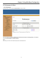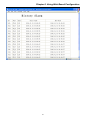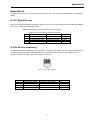
1
ETU08
8 E1 Inverse Multiplexer
LEGAL
The information in this publication has been carefully checked and is believed to be entirely accurate at the time of
publication. CTC Union Technologies assumes no responsibility, however, for possible errors or omissions, or for any
consequences resulting from the use of the information contained herein. CTC Union Technologies reserves the right to
make changes in its products or product specifications with the intent to improve function or design at any time and
without notice and is not required to update this documentation to reflect such changes.
CTC Union Technologies makes no warranty, representation, or guarantee regarding the suitability of its products for
any particular purpose, nor does CTC Union assume any liability arising out of the application or use of any product
and specifically disclaims any and all liability, including without limitation any consequential or incidental damages.
CTC Union products are not designed, intended, or authorized for use in systems or applications intended to support or
sustain life, or for any other application in which the failure of the product could create a situation where personal injury
or death may occur. Should the Buyer purchase or use a CTC Union product for any such unintended or unauthorized
application, the Buyer shall indemnify and hold CTC Union Technologies and its officers, employees, subsidiaries,
affiliates, and distributors harmless against all claims, costs, damages, expenses, and reasonable attorney fees arising
out of, either directly or indirectly, any claim of personal injury or death that may be associated with such unintended or
unauthorized use, even if such claim alleges that CTC Union Technologies was negligent regarding the design or
manufacture of said product.
TRADEMARKS
Microsoft is a registered trademark of Microsoft Corp.
HyperTerminal™ is a registered trademark of Hilgraeve Inc.
WARNING:
This equipment has been tested and found to comply with the limits for a Class A digital device, pursuant to Part 15 of
the FCC Rules. These limits are designed to provide reasonable protection against harmful interference when the
equipment is operated in a commercial environment. This equipment generates, uses, and can radiate radio frequency
energy and if not installed and used in accordance with the instruction manual may cause harmful interference in which
case the user will be required to correct the interference at his own expense. NOTICE: (1) The changes or modifications
not expressively approved by the party responsible for compliance could void the user's authority to operate the
equipment. (2) Shielded interface cables and AC power cord, if any, must be used in order to comply with the emission
limits.
CISPR PUB.22 Class A COMPLIANCE:
This device complies with EMC directive of the European Community and meets or exceeds the following technical
standard. EN 55022 - Limits and Methods of Measurement of Radio Interference Characteristics of Information
Technology Equipment. This device complies with CISPR Class A.
WARNING:
This is a Class A product. In a domestic environment this product may cause radio interference in which case the user
may be required to take adequate measures.
CE NOTICE
Marking by the symbol CE indicates compliance of this equipment to the EMC directive of the European Community.
Such marking is indicative that this equipment meets or exceeds the following technical standards: EN
55022:1994/A1:1995/A2:1997 Class A and EN61000-3-2:1995, EN61000-3-3:1995 and EN50082-1:1997
CTC Union Technologies Co., Ltd.
Far Eastern Vienna Technology Center (Neihu Technology Park)
8F, No. 60, Zhouzi St.
Neihu, Taipei, 114
Taiwan
Phone: +886-2-2659-1021
FAX: +886-2-2799-1355
ETU08
8 E1 Inverse Multiplexer
User Manual
Version 0.9a Draft Aug 2008
This manual supports the following models:
ETU08-8E/AC
ETU08-8E/DC
This document is the first official release manual. Please check CTC Union's website for any updated manual or contact
us by E-mail at [email protected]. Please address any comments for improving this manual or to point out omissions or
errors to [email protected]. Thank you.
1. Overview................................................................................................................................................. 7
1.1 Features ............................................................................................................................................7
1.2 Application .......................................................................................................................................8
2 Setting Up................................................................................................................................................ 9
2.1 Front Panel........................................................................................................................................9
2.2 LED Indication..................................................................................................................................9
2.3 Loopback Control............................................................................................................................10
2.4 Rear Panel.......................................................................................................................................10
3 Configuration ........................................................................................................................................ 11
3.1 Navigating the Menu ....................................................................................................................... 11
3.2 Menu Trees ..................................................................................................................................... 11
3.3 Menu Screen Convention .................................................................................................................16
3.3.1 Log Screen ............................................................................................................................16
3.3.2 Menu screen..........................................................................................................................17
3.3.3 Main Menu............................................................................................................................18
3.4 Configuring System Parameters ........................................................................................................19
3.4.1 Configuring System Time .......................................................................................................20
3.4.2 Configuring System Description .............................................................................................20
3.4.3 Configuring SNTP .................................................................................................................20
3.4.4 Configuring LAN Management Interface .................................................................................21
3.4.5 Configuring SNMP ................................................................................................................22
3.4.6 Configuring EOC ...................................................................................................................24
3.4.7 Configuring System Application Parameters ............................................................................25
3.4.8 Setting User Password............................................................................................................25
3.5 Configuring Interfaces .....................................................................................................................26
3.5.1 Configuring E1 Interfaces.......................................................................................................26
3.5.2 Configuring 10/100Base-Tx Port.............................................................................................27
3.5.3 Configuring E1 Switch Parameters ..........................................................................................28
3.6 Configuring Alarm Threshold ...........................................................................................................29
3.7 Save & Factory Default....................................................................................................................29
4 Monitoring Performance & Alarm......................................................................................................... 31
4.1 Displaying E1 Statistics ...................................................................................................................31
4.2 Displaying Current 15Min Performance ............................................................................................32
4.3 Displaying Current 24 Hour Performance ..........................................................................................33
4.4 Displaying History 15 Minute Performance .......................................................................................33
4.5 Displaying History 24 Hour Performance ..........................................................................................34
4.6 Clearing History 15 Min data ...........................................................................................................34
4.7 Clearing History 24 Hour data ..........................................................................................................34
4.10 Displaying Alarm...........................................................................................................................35
4.11 Displaying Current Alarm...............................................................................................................35
4.12 Displaying Historical Alarm ...........................................................................................................36
5 Maintenance.......................................................................................................................................... 37
5.1 Performing Loop Back.....................................................................................................................37
5.3 Updating Firmware ..........................................................................................................................40
5.4 Displaying Identity Information........................................................................................................41
6 Configuring with Web ........................................................................................................................... 43
6.1 Login..............................................................................................................................................43
6.2 Configuration..................................................................................................................................44
6.2.1 System..................................................................................................................................44
6.2.2 Interface ................................................................................................................................49
6.2.3 Alarm Threshold ....................................................................................................................52
6.2.4 Save & Reset.........................................................................................................................53
6.3 Performance & Alarm......................................................................................................................54
6.3.1 Performance ..........................................................................................................................54
6.3.2 Alarm....................................................................................................................................55
6.4 Maintenance....................................................................................................................................57
6.4.1 Test.......................................................................................................................................57
6.4.2 Update (Recommended) .........................................................................................................59
i
Appendix A ...............................................................................................................................................61
A.1 E1 Signal Pin-out............................................................................................................................ 61
A.2 RJ-45 wire numbering..................................................................................................................... 61
ii
Chapter 1. Introduction
1. Introduction
ETU08 is a 4/8 E1 inverse multiplexer enabling the transport of high speed data, MPEG-2 or broadband
services over 1 to 4/8 E1 links. Using a proprietary E1 frame alignment for splitting a single 8M/16M data
over 1 to 4/8 E1 links or vice versa, the ETU08 identifies and aligns this inverse data channel dynamically
with minimal delay variation among the E1 links.
10/100Base-TX interfaces make ETU08 an ideal solution for high speed broadband application. The inverse
aggregation bandwidth is scalable as Nx1.984 Mbps [N=1–4/8] with maximum payload bandwidth at 7.936
Mbps or 15.872Mbps.
It can be managed locally by connecting a VT-100 emulated PC to the console port or remotely through
Telnet/SNMP/Web server access. Administration, Maintenance, and Provisioning (OAM&P) are provisioned
with the use of 12Kbps embedded operation channel (EOC) that runs through the inverse link. Configured
with individual IP address for local and remote unit, ETU08 is accessible to the Internet users who are
managing the units from a remote location.
To ensure operation continuity and accommodate field requirement, ETU08 offers choices of AC and DC
power.
1.1 Features
Connect one high speed broadband over 1-4/8 E1 links
Automatically scale up and down E1 links according to link availability.
Support data rates 1.984XN[1-4/8]Mbps.
Use 12Kbps EOC channel for remote configuration and OAM&P.
Comply with ITU-T G.703 and support PCM31C format.
Allow a maximum delay of 64 ms among E1 links.
Specifications
Inverse multiplexing
E1 alignment:
Maximal delay:
Data rate:
Proprietary method by labeling E1 frames. E1 frame is labeled from
1-512 using SA7-SA8 spare bits
64 ms[512 frame buffer]
Nx1.984Mbps,N=1-4/8, 12Kbps EOC channel is embedded in SA4SA6 spare bits.
E1 Interface
Standard:
No. of E1 output:
Line rate:
Line Code:
Framing:
Pulse shape:
Impedance:
Connection Type:
ITU-T G.703, G.704,
1–4/8,scaled down automatically per E1 alarms
2048 Kbps +/- 50 ppm
HDB3
PCM31C
Meet ITU-T G.703
Balanced 120Ω+/-5% resistive or unbalanced 75Ω+/-5% resistive,
software programmable
RJ-45 or BNC
LAN Interface
Standard:
Interface:
Data Rate:
Bridging Capability:
IEEE 802.3 / IEEE 802.3u
IEEE 802.3/802.3u 10/100 Base-T
N x1.984Mbps[N=1-4/8]
Complied with IEEE 802.1d transparent bridge
Supports up to 128 MAC addresses learning
Supports bridge filtering function
Connection Type:
RJ-45 2ports
Ethernet packet size: maximin packet
size as 1518,1522,1536and 1912 bytes.
support
7
Chapter 1. Introduction
Power
AC [Default], DC is optional
AC:
90 - 260 V @ 50-60 Hz, 0.2A
DC:
-36~ -72 V,0.2A
Network management
CID interface:
EOC channel:
SNMP:
VT-100/RS-232C/Telnet/SNMP/Web server
12Kbps
meet IETF RFC1157,1212 and 2495@10/100Based Tx with RJ-45
connector
Alarm and Performance
Meet G.821 and G.826 for E1 interface
Form C dry relay alarm output
Maintenance
Loopback: LL,RL and NL(local payload loopback)
Mechanical
Desktop (WxHxD)
Rackmount
29.1 cm x 51cm x 17.8 cm
19 inches wide and 1U height
Ordering Information:
ETU08-8E -4E /AC /DC
/AC: Specify power source.
/DC * AC
* DC
-xE: Specify E1 number.
4 4E1
8 8E1
1.2 Application
.
ETU08
LAN
4/8E1
4/8E1
ETU08
SDH/PDH
12K bps EOC over SDH/PDH Network
Figure A.1: Typical ETU08 application
8
LAN
Chapter 2. Overview
2. Overview
Provides a detailed description of the Front Panel controls, indicators and
their functions and connections of the Rear Panel.
Lists the configuration parameters for CID port.
Explains notations of command syntax and shows valid entry.
2.1 Front Panel
Figures 2.1 illustrates the Front Panel of typical ETU08 unit with LAN and E1 status indicators, loop back
pushbuttons, Telnet/SNMP and CID management interfaces.
Appendix A specifies the ETU08 connector pin assignments.
ETU08-8E
Console Port
10/100Base-Tx
Port Indicators
Loop Back Indicators
and pushbuttons
Power
E1 Indicators
Telnet/SNMP Port
ACO Indicator
And pushbutton
Figure 2.1 : Front Panel of ETU08
2.2 LED Indication
ETU08,by interface category, contains purpose-driven LEDs for illustrating the Configuration and Operational
status of the unit. Table 2.1 list the function for these LED.
Table 2.1: ETU08 LEDs Indication
LED
Color
Status
Function
LNK
Green
ON
LAN port is connected to an external device.
10/100
Green
ON
LAN port is working at 100M bps
OFF
LAN port is working at 10M bps
ON
LAN port is working in full duplex mode
OFF
LAN port is working in half duplex mode
DUP
Green
SYN
Green
ON
E1 link is synchronized.
ALM
Red
ON
E1 link has LOS, AIS or LOF occurred.
Blinking 0.5s OFF, 0.5s ON
CRC-4 error is present at E1 port.
Blinking 3s OFF, 0.5s ON
Active alarm is present at the remote E1 port.
ACO
Yellow
ON
Audio alarm of the alarm happened before is
relieved.
PWR
Green
ON
Power is on.
Note that the SYN and ALM indicators will both turn OFF while the specific E1 port is configured to un-used.
ETU08 indicates the most E1 severe event only while multiple events occurred simultaneously. The severity
descendant
is LOS, AIS, LOF, CRC-4, and RAI with LOS the highest.
9
Chapter 2. Overview
2.3 Loopback Control
There are varieties of Loop Back(LB) designed in ETU08 enabling the diagnostics performed at E1 ports or
user DTE interfaces as illustrated in Figure 2.2 below.
Remote ETU08
Local ETU08
4/8E1 SDH/PDH 4/8E1
LAN
LLA
LLB
RLA
LAN
RLB
Figure 2.2 Employing multiple points of loop back
Table 2.2: Loopback performing at use DTE or E1 ports
Choice
Description
LLA
Loop the signal locally at E1interface toward DTE direction.
LLB
Loop the signal locally at E1 interface toward network direction.
RLA
Loop the signal remotely at E1 interface toward network direction.
RLB
Loop the signal remotely at E1 interface toward DTE direction.
Note that the Point of Loop Back ( POL ) is specified in the figure above.
When you initiate this test, the status of loop back for all ports are shown in real time basis.
Table 2.3: ETU08 LEDs Indication and Button Control
Item
LED/Button Color
LL ( E1 )
Button
LL ( E1 )
LED
LED display
Function
Toggle this button to start and stop LL.A
Yellow
ON
LLA is in progress.
Blinking 0.5s OFF, 0.5s ON RLB is in progress.
RL ( E1 )
Button
RL ( E1 )
LED
Toggle this button to start and stop RLA.
Yellow
ON
RLA is in progress.
Blinking 0.5s OFF, 0.5s ON RLB is in progress
2.4 Rear Panel
Figure 2.3 illustrates the Rear Panel of typical ETU08-8E unit with unbalanced and balance E1, LAN port,
and AC/DC power connectors.
AC Power Receptacle
10/100/Base-Tx Port1&2
DC Power
Connector
E1 120 ohm
Alarm I/O Interface
E1 BNC Connectors
E1 BNC Connectors
Channel 5, 6, 7, 8
Channel 1, 2, 3, 4
Figure 2.3 Rear Panel of ETU08(8E1)
10
E1 120 ohm
Chapter 3. Provisioning
3. Provisioning
3.1 Navigating the Menu
Management interfaces
If required, ETU08 can be re-configured. The ETU08 Configuration, Monitoring, and Diagnostic operation are
performed using any of the following methods:
ASCII terminal connected to Console port
An SNMP-based management system.
Telnet accessed LAN port
Configuring the Console Port
ETU08 includes a V.24/RS-232 asynchronous DCE port, designated Console and terminated in a 9-pin Dtype female connector. This Console port continuously monitors the incoming data stream and immediately
responds to any input string received through this port.
The ETU08 Console port can be configured to communicate at the following setting:
Terminal Mode:
Baud rate:
Data bits:
Parity:
Stop bits:
Flow Control:
VT-100
38400 bps
8
None
1
None
3.2 Menu Trees
The menu structure for ETU08 is a multi-layered menu tree. Each menu level consists of menu elements,
which may be either a main menu or a sub-menu item. Use these menu trees as a reference while
configuring parameters, collecting event statistics and performing diagnostics.
A 5 layers Menu Tree for the unit is illustrated in Figure 3.1 through Figure 3.4.
The first 3 hierarchy
Viewing from Main Menu, the second layer “ 1. Configuration, 2.Performance Monitoring & Alarm, and 3.
Maintenance “ and all its tributary are shown in Figure 3.1.
11
Chapter 3. Provisioning
Figure 3.1: The first 3 Level Menu Tree
Main Menu
>> 1. Configuration
>> System
>> Interface
>> Alarm Threshold
>> Factory Default
>> Save
>> 2. PM&Alarm
>> Performance
>> Alarm
>> 3. Maintenance
>> Loopback Test
>> PRBS Test
>> Firmware Update
>> Inventory
12
Chapter 3. Provisioning
Figure 3.2: Configuration and its tributary I
Main Menu
>> Configuration
>> 1. System
>> 1. Time & Date
>> 2. SNTP Configure
>> 1. SNTP State
>> 2. SNTP Server IP
>> 3. LAN Configure
>> 1. IP address
>> 2. Subnet Mask
>> 3. Gateway Addr
>> 4.Mac Addr
>> 4. SNMP Configure
>> 1. Community CFG
>>
>>
>>
>>
>> 2. Trap CFG
5. EOC Configure
>> 1. Local IP
>> 2. Remote IP
6. Route Configure
>> Add Route
>> Delete Route
7. APP Configure
>> 1.Rate Unit
>> 2.Data Unit
>> 3.Clock Mode
>>
4.Max Packet Length
>>
5.InBand Configure State
Read Com; Write Com;
Trap Com
TrapIP Addr;Port
E1
Recovery;
Crystal
1536;
1552
Disabled;
Enabled
8. Password Change
>> 2. Interface
>> 1. Channel (1~4 or 1~8)
>> 1. Channel State
>> 2. Channel Use
>> 3. Frame Type
>> 4. Impedance
13
:Equipped; N0_Equipped
: Used; Unused
: PCM31C
: 120 ohm; 75 ohm
Chapter 3. Provisioning
Figure 3.3: Configuration and its tributary II
Main Menu
>>
Configuration
>> 2. Interface
>> 3. 10/100Base-Tx Port
>> 1. Port 1
>> 1.State
:Up;Down
>> 2.Auto Negotiation :Disabled; Enabled
>> 3.Speed
:10M; 100M;
>> 4.Duplex
:Half; Full
>> 5.Flow Control
:Disabled; Enabled
>> 2. Port 2
>> 6. E1 Switch
>> 1. Switch Mode
: Auto; Manual
>> 2. Switch BER Threshold
: 10e-3; 10e-4; 10e-5;
>> 3. Bandwidth Reserve Time : 30 ~ 65535 S
>> 4. Bandwidth Response Time : 1~30 S
>> 3. Alarm Threshold
>> 1. Channel(1~4 or 1~8)
>> 1. ES 15 Min
>> 2. ES 24 Hour
>> 3. SES 15 Min
>> 4. SES 24 Hour
>> 5. UAS 15 Min
>> 6. UAS 24 Hour
>> 4. Factory default
>> 5. Save
14
Chapter 3. Provisioning
Figure 3.4: PM&Alarm, Maintenenace and its tributary
Main Menu
>> 2. PM&Alarm
>> 1.Performance
>> 1. Channel(1~4 or 1~8)
>>
1. Current 15min.
>>
2. Current 24hour
>>
3. History 15min.
>>
4. History 24hour
>>
5. His 15min Clear
>>
6. His 24hour Clear
>> 2. Alarm
>> 1. Current Alarm
>> 2. History Alarm
>> 3. History Clear
>> 3. Maintenance
>> 1. Loopback Test
>> 1. Type
: LLA;RLA;
>> 2. Channel Set :Channel 1~4 or 1~8
>> 3. Start Test
: Start; Stop
>> 2. PRBS Test
>> 1. Channel Set :Channel 1~4 or 1~8
>> 2. Start
: Start; Stop
>> 3. Firmware Update
>> 1. Host IP
>> 2. Start Update
>> 3. Reset
>> 4. Inventory
>> 1. Product
>> 2. S/W Version
>> 3. H/W Version
>> 4. Vendor
>> 5. Manf. Date
15
Chapter 3. Provisioning
3.3 Menu Screen Convention
3.3.1 Log Screen
If you choose to access system with Console Port, you will firstly get the Log Screen illustrated below. Both
for local and remote,
Default user name: Local
Default password: admin
In excess of CRC-4 10e-5 for switching
Auto or Manual E1 Switch
CTC Union Technologies ETU08
----------------------------E1 Switch
:
Manual
10e-5
CH_1
: Used
Normal
CH_5
: Used
CH_2
: Used
Normal
CH_6
: Used
CH_3
: Used
Normal
CH_7
: Used
CH_4
: Used
Normal
CH_8
: Used
10/100Base-TX : 15872K
Down
Up_100M_FULL
================================================
1. Local
2. Remote
Normal
Normal
Normal
Normal
->
->
--------------------------------------------------------------------Tab]Previous Item SPACE]Next Item ENTER]Accept Item Ctrl-N]Main Menu
Figure 3.5 Logon Screen
16
Normal, LOS,
LOF, AIS,
CRC-4, RDI
Or BIP-8
shown
Full or half
duplex
for LAN
traffic
Chapter 3. Provisioning
3.3.2 Menu screen
After log in the system, the Menu Screen will show as below. It always contains five user operating areas
which are Identity Information, Real Time Status, Operating Field, Input Field, and Function Keys.
There are three main menus on Menu Screen including Configure (Details see Section 3.4~3.7), PM &
Alarm (Details see Chapter 4), and Maintenance (Details see Chapter 5).
Identity Information
Real Time
Status
CTC Union Technologies ETU08
----------------E1 Switch
:
Auto
10e-5
CH_1
: Used
NORMAL
CH_5
: Used
CH_2
: Used
NORMAL
CH_6
: Used
CH_3
: Used
NORMAL
CH_7
: Used
CH_4
: Used
NORMAL
CH_8
: Used
10/100Base-Tx : 15872K
Up_100M_FULL
Down
=================================================
\Local\Main
1. Configure
2. PM & Alarm
3. Maintenance
Operating Field
Input Field
Function Keys
NORMAL
NORMAL
NORMAL
NORMAL
->
->
->
--------------------------------------------------------------------Tab]Previous Item
1..3]Select Item
SPACE]Next Item
ENTER]Accept Item
Ctrl-N]Main Menu
Ctrl-R]Screen Refresh
Esc]Quit
Figure 3.6 Main Menu Screen
Table 3.3: Five user operating areas of the Menu Screen.
Identity Information:
Real Time Status:
The one-line top most area that shows Name of Vendor and Product Model.
This is the multi-line area above the double dotted line that provides user
interface status and alarm message.
Operating Field:
This is the area above the single dotted line that provides content of submenu and allowed for users’ intervention.
Prompt Showing Field: The area beneath the dotted line that shows options specific to menu or
sub-menu items.
Function Keys:
The area right beneath the input field that lists the function keys specific to
the operation of the menu currently displayed.
Cursor Operation
To select a specific field or navigate the console screen, refer to the table below for further details. But
reverting to main menu or refreshing screen, you need to press “ N “ or “ R “ letter key respectively while
holding down the Control ( Ctrl ) key.
Keyboard Command
Tab
Space
Ctrl+ N
1 …N]
Enter
Ctrl+ R
Esc
Description
Tabs to previous item.
Advances to next item.
Reverts to Main Menu.
Fields enclosed in brackets [ ] offer a list of selections.
Validates the fields selected.
Refreshes the entire screen.
Escapes to previous page.
17
Chapter 3. Provisioning
3.3.3 Main Menu
Press “Ctrl+N” to get Main menu illustrated below. It shows both Local and Remote information including
LAN IP, Line Rate, LAN port Status, and E1 channel statuses. As shown below, local information is on the
left, remote is on the right.
CTC Union Technologies ETU08
----------------172. 24. 1.180
172. 24. 1.181
+--------+
+--------+
15872K_Crystal |
|
|
|15872K_Crystal
|
|-------------><-------------|
|
LAN Port1->|
|-------------><-------------|
|->LAN Port1
Down |
|-------------><-------------|
| Down
100M_FULL<-|
|-------------><-------------|
|<-100M_FULL
LAN Port2->|
|-------------><-------------|
|->LAN Port2
Up |
|-------------><-------------|
| Up
100M_FULL<-|
|-------------><-------------|
|<-100M_FULL
|
|-------------><-------------|
|
Fiber Module->|
|
|
|
Equipped<-|
|
|
|
+--------+
+--------+
CH_1:
CH_2:
CH_3:
CH_4:
USED_NORMAL
USED_NORMAL
USED_NORMAL
USED_NORMAL
CH_5:
CH_6:
CH_7:
CH_8:
USED_NORMAL
USED_NORMAL
USED_NORMAL
USED_NORMAL
CH_1:
CH_2:
CH_3:
CH_4:
USED_NORMAL
USED_NORMAL
USED_NORMAL
USED_NORMAL
CH_5:
CH_6:
CH_7:
CH_8:
USED_NORMAL
USED_NORMAL
USED_NORMAL
USED_NORMAL
Press any key to continue...Tab]Previous Item SPACE]Next Item ENTER]Accept Item Ctrl-N]Main Menu
Figure 3.7 Main Status Overview
18
Chapter 3. Provisioning
3.4 Configuring System Parameters
Apply the menu selection sequence: Local >> Main >> Configure, to get the Configure Menu illastrated
below.
CTC Union Technologies ETU08
----------------E1 Switch
:
Auto
10e-5
CH_1
: Used
NORMAL
CH_5
: Used
CH_2
: Used
NORMAL
CH_6
: Used
CH_3
: Used
NORMAL
CH_7
: Used
CH_4
: Used
NORMAL
CH_8
: Used
10/100Base-Tx : 15872K
Up_100M_FULL
Up_100M_FULL
=================================================
\Local\Main\Configure
1.
2.
3.
4.
5.
System
Interface
Alarm Threshold
Factory Default
Save
NORMAL
NORMAL
NORMAL
NORMAL
->
->
->
--------------------------------------------------------------------Tab]Previous Item
1..5]Select Item
SPACE]Next Item
ENTER]Accept Item
Ctrl-N]Main Menu
Ctrl-R]Screen Refresh
Esc]Quit
Figure 3.8 Configuration Menu
The first item on the Configure Menu is the System Menu. This menu allows you to view and set specific
ETU08 system parameters.
To access the System Parameters, apply the menu selection sequence: Local >> Main >> Configure >>
System.
CTC Union Technologies ETU08
----------------E1 Switch
:
Auto
10e-5
CH_1
: Used
NORMAL
CH_5
: Used
CH_2
: Used
NORMAL
CH_6
: Used
CH_3
: Used
NORMAL
CH_7
: Used
CH_4
: Used
NORMAL
CH_8
: Used
10/100Base-Tx : 15872K
Up_100M_FULL
Down
=================================================
\Local\Main\Configure\System
1.
2.
3.
4.
5.
6.
7.
8.
System
System
System
System
System
System
System
System
Time and Date
Description
SNTP Configure
LAN Configure
SNMP Configure
EOC Configure
APP Configure
Password Change
NORMAL
NORMAL
NORMAL
NORMAL
: 2008.01.01 00:04:33
: XXXXX
->
->
->
->
->
--------------------------------------------------------------------Input format:Year-Month-Day-Hour[24]-Minute-Second
Tab]Previous Item SPACE]Next Item
Ctrl-N]Main Menu
1..8]Select Item
ENTER]Accept Item Ctrl-R]Screen Refresh Esc]Quit
Figure 3.9 System Menu
19
Chapter 3. Provisioning
There are 8 type of System Parameters required to configure or change as detailed in the following table.
Item
1. System Time
2. System Description
3. SNTP Configure
4. LAN Configure
5. SNMP Configure
Description
Configure system date and time.
Configure system Description
Configure SNTP
Configure LAN
Configure SNMP
6. EOC Configure
7. APP Configure
8. User Password
Configure EOC
Configure common application param
Specify the user password.
3.4.1 Configuring System Time
The System Menu allows you to configure or change the system parameters of the ETU08.
To access these parameters, apply the menu selection sequence: Local >> Main >> Configure >>
System>> System Time and Date.
To configure system date and time:
Move cursor to 3. System Time and Date and type in this data in “ Year-Month-Day-Hour[ 24 ]
Minute-Second “ format.
3.4.2 Configuring System Description
The System Menu allows you to configure or change the system description of the ETU08.
To access this parameter, apply the menu selection sequence: Local >> Main >> Configure >> System>>
System Description.
To configure system description:
You can input alphabetic characters (a..z, A..Z), number (0..9) and hyphen (-), not more than 19
characters
3.4.3 Configuring SNTP
When this parameter Enabled, the ETU08 will retrieve the current time from a remote SNTP Server whose IP
address is specified herewith. The System Menu allows you to configure the SNTP Server. To access these
parameters, apply the menu selection sequence: Local >> Main >> Configure >> System >> SNTP_CFG .
( See Figure 3.6 )
CTC Union Technologies ETU08
----------------E1 Switch
:
Manual
10e-5
CH_1
: Used
NORMAL
CH_5
: Used
CH_2
: Used
NORMAL
CH_6
: Used
CH_3
: Used
NORMAL
CH_7
: Used
CH_4
: Used
NORMAL
CH_8
: Used
10/100Base-Tx : 15872K
Down
Down
=================================================
\Local\Main\Configure\System\SNTP_CFG
1. SNTP State
2. SNTP Server IP
NORMAL
NORMAL
NORMAL
NORMAL
: Enabled
: 220.130.158. 52
--------------------------------------------------------------------1) Disabled; 2) Enabled;
Tab]Previous Item SPACE]Next Item
Ctrl-N]Main Menu
1..2]Select Item
ENTER]Accept Item Ctrl-R]Screen Refresh Esc]Quit
Figure 3.10 Time Configuration
20
Chapter 3. Provisioning
To configure the SNTP,
Move cursor to 4. System SNTP Configure from System Menu.
The SNTP Menu appears.
Select Enabled or Disabled.
In the SNTP Server IP field, type in the IP address in decimal dot format xxxx.xxxx.xxxx.xxxx .
3.4.4 Configuring LAN Management Interface
To access LAN parameters, apply the menu selection sequence: Local >> Main >> Configure >>
System>> LAN_CFG as shown below.
CTC Union Technologies ETU08
----------------E1 Switch
:
Auto
10e-5
CH_1
: Used
NORMAL
CH_5
: Used
CH_2
: Used
NORMAL
CH_6
: Used
CH_3
: Used
NORMAL
CH_7
: Used
CH_4
: Used
NORMAL
CH_8
: Used
10/100Base-Tx : 15872K
Up_100M_FULL
Up_100M_FULL
=================================================
\Local\Main\Configure\System\LAN_CFG
1.
2.
3.
4.
IP Address
Subnet Mask
Gateway Addr
Mac Addr
:
:
:
:
NORMAL
NORMAL
NORMAL
NORMAL
172. 24. 1.180
255.255.255. 0
172. 24. 1.254
00:02:ab:90:0b:ef
--------------------------------------------------------------------Format : xxx.xxx.xxx.xxx
Tab]Previous Item SPACE]Next Item
Ctrl-N]Main Menu
1..4]Select Item
ENTER]Accept Item Ctrl-R]Screen Refresh Esc]Quit
Figure 3.11 LAN Menu
To configure the LAN Management Interface,
Move cursor to 5. System LAN Configure of System Menu.
The LAN Menu appears.
Specify IP address for this LAN interface.
Type the proper Subnet Mask.
Specify the Next hop IP address in the “ Gateway Addr. “ field.
Read only.The Mac Address of the system.
Note:
LAN IP should not be in the same sub net with EOC IP.
The Mac Addr should not be the same as Remote Mac Addr.
The IP or sub net mask has to be specified in decimal dot format.
21
Chapter 3. Provisioning
3.4.5 Configuring SNMP
SNMP Overview
The Simple Network Management Protocol (SNMP) is an application-level protocol used in network
management to gather information from network devices. Each device runs an SNMP Agent that collects
management data. A Network Management System (NMS), such as MS- MIB browser professional, HP
OpenView , communicates with a SNMP Agent embedded in the ETU08 to obtain specific parameters or
variables.
In most case, an SNMP Manager issues a request message (Get) to an SNMP Agent, now namely the
ETU08, for retrieving management data. When the ETU08 receives the SNMP Get request, it transmits a
response ( positive or negative) to the NMS. However, when certain significant events are being trapped b y
the SNMP Agent, these unsolicited SNMP Trap are sent to the SNMP NMS automatically.
SNMP Gets and Sets
An SNMP "Get" or “Set” allows the management station (NMS) to retrieve an object value from a managed
station (ETU08). The ETU08 will execute the “Get” or “Set” request with the in-built SNMP protocol stack.
Traps
Traps are used to inform the NMS of an alert being occurred in the system (example:E1 loss sync). They are
sent at the start and completion of an alarm condition. The ETU08 can send traps to the IP addressable
destinations (e.g. NMS, or a printer )
To access these SNMP parameters, apply the menu selection sequence: Local >> Main >> Configure >>
System>> SNMP_CFG as shown below.
CTC Union Technologies ETU08
----------------E1 Switch
:
Auto
10e-5
CH_1
: Used
NORMAL
CH_5
: Used
CH_2
: Used
NORMAL
CH_6
: Used
CH_3
: Used
NORMAL
CH_7
: Used
CH_4
: Used
NORMAL
CH_8
: Used
10/100Base-Tx : 15872K
Up_100M_FULL
Up_100M_FULL
=================================================
\Local\Main\Configure\System\SNMP_CFG
1. Community CFG
2. Trap CFG
NORMAL
NORMAL
NORMAL
NORMAL
->
->
--------------------------------------------------------------------Tab]Previous Item
1..2]Select Item
SPACE]Next Item
ENTER]Accept Item
Ctrl-N]Main Menu
Ctrl-R]Screen Refresh
Esc]Quit
Figure 3.12 SNMP Menu
To access the SNMP Community and Trap parameters,
Move cursor to 6. System SNMP Configure of System Menu.
The SNMP Menu appears.
Position cursor on 1. Community CFG and hit “ Enter “ key to access the Community Menu.
( See Figure 3.13 )
Position cursor on 2. Trap CFG and hit “ Enter “ key to access the Trap Menu. ( See Figure 3.14 )
22
Chapter 3. Provisioning
3.4.4.1 Configuring Community Parameter
To access these SNMP parameters, apply the menu selection sequence: Local >> Main >> Configure >>
System>> SNMP_CFG >> Community_CFG as shown below.
CTC Union Technologies ETU08
----------------E1 Switch
:
Auto
10e-5
CH_1
: Used
NORMAL
CH_5
: Used
CH_2
: Used
NORMAL
CH_6
: Used
CH_3
: Used
NORMAL
CH_7
: Used
CH_4
: Used
NORMAL
CH_8
: Used
10/100Base-Tx : 15872K
Up_100M_FULL
Up_100M_FULL
=================================================
\Local\Main\Configure\System\SNMP_CFG\Community_CFG
1. Read Community
2. Write Community
3. Trap Community
NORMAL
NORMAL
NORMAL
NORMAL
: public
: secret
: secret
--------------------------------------------------------------------Tab]Previous Item
1..3]Select Item
SPACE]Next Item
ENTER]Accept Item
Ctrl-N]Main Menu
Ctrl-R]Screen Refresh
Esc]Quit
Figure 3.13 SNMP Community String Setting
There are 3 categories of SNMP Community: Read-Only Community, Read-Write Community
and Trap Community.
To access the SNMP Community parameters,
Move cursor to 1. Read Community and specify the name of the community with
MIB access level of Read Only.
Move cursor to 2. Write Community and specify the name of the community with
MIB access level of Read & Write.
Move cursor to 3. Trap Community and specify the name of the community to
which the Trap will send.
23
Chapter 3. Provisioning
3.4.4.2 Configuring Trap Parameter
To access these Trap parameters, apply the menu selection sequence: Local >> Main >> Configure >>
System>> SNMP_CFG >> Trap_CF as shown below.
CTC Union Technologies ETU08
----------------E1 Switch
:
Auto
10e-5
CH_1
: Used
NORMAL
CH_5
: Used
CH_2
: Used
NORMAL
CH_6
: Used
CH_3
: Used
NORMAL
CH_7
: Used
CH_4
: Used
NORMAL
CH_8
: Used
10/100Base-Tx : 15872K
Up_100M_FULL
Down
=================================================
\Local\Main\Configure\System\SNMP_CFG\Trap_CFG
1. TrapIP Addr1
2. TrapIP Addr2
3. TrapIP Addr3
: 172. 24.
: 172. 24.
: 172. 24.
NORMAL
NORMAL
NORMAL
NORMAL
1.125 : 162
1.251 : 162
1.252 : 162
--------------------------------------------------------------------Format : xxx.xxx.xxx.xxx(IP addr):xxx(Port 1-900)
Tab]Previous Item SPACE]Next Item
Ctrl-N]Main Menu
1..3]Select Item
ENTER]Accept Item Ctrl-R]Screen Refresh Esc]Quit
Figure 3.14 Trap Menu
To access the SNMP Trap parameters,
Move cursor to 1. Trap IP Address 1 and specify the IP address and TCP port
number of the external SNMP Manager 1.
Move cursor to 2. Trap IP Address 2 and specify the IP address and TCP port
number of the external SNMP Manager 2.
Move cursor to 3. Trap IP Address 3 and specify the IP address and TCP port
number of the external SNMP Manager 3.
3.4.6 Configuring EOC
The System Menu allows you to configure the Embedded Operation Channel management traffic
transported between tow two ETU08s. To perform the configuration, apply the menu selection sequence:
Local >> Main >> Configure >> System >> EOC_CFG as shown below.
CTC Union Technologies ETU08
----------------E1 Switch
:
Auto
10e-5
CH_1
: Used
NORMAL
CH_5
: Used
CH_2
: Used
NORMAL
CH_6
: Used
CH_3
: Used
NORMAL
CH_7
: Used
CH_4
: Used
NORMAL
CH_8
: Used
10/100Base-Tx : 15872K
Up_100M_FULL
Down
=================================================
\Local\Main\Configure\System\EOC_CFG
1. Local IP
2. Remote IP
: 172. 24.
: 172. 24.
NORMAL
NORMAL
NORMAL
NORMAL
1.180
1.181
--------------------------------------------------------------------Format : xxx.xxx.xxx.xxx
Tab]Previous Item SPACE]Next Item
Ctrl-N]Main Menu
1..2]Select Item
ENTER]Accept Item Ctrl-R]Screen Refresh Esc]Quit
Figure 3.15 EOC Menu
To configure the EOC,
Move cursor to 1. Local IP and specify the IP address of the local ETU08
Move cursor to 2. Remote IP and specify the IP address of the remotely connected ETU08.
24
Chapter 3. Provisioning
3.4.7 Configuring System Application Parameters
The System Menu allows you to configure the common application parameters. To perform the configuration,
apply the menu selection sequence: Local >> Main >> Configure >> System >> System APP Configure
as shown below.
CTC Union Technologies ETU08
----------------E1 Switch
:
Auto
10e-5
CH_1
: Used
NORMAL
CH_5
: Used
CH_2
: Used
NORMAL
CH_6
: Used
CH_3
: Used
NORMAL
CH_7
: Used
CH_4
: Used
NORMAL
CH_8
: Used
10/100Base-Tx : 15872K
Up_100M_FULL
Down
=================================================
\Local\Main\Configure\System\Application Configure
1.
2.
3.
4.
5.
Rate Unit
Data Rate
Clock mode
Max Packet Length
InBand Configure State
:
:
:
:
:
NORMAL
NORMAL
NORMAL
NORMAL
E1
15872/8
Crystal
1536
Enabled
--------------------------------------------------------------------Tab]Previous Item
1..5]Select Item
SPACE]Next Item
ENTER]Accept Item
Ctrl-N]Main Menu
Ctrl-R]Screen Refresh
Esc]Quit
Figure 3.16 EOC Menu
To configure the application param,
1. Rate Unit, Read-only, it specifies the unit of rate.
E1: 1984K;
Time Slot:64K
2. Data Rate, Read-only, it specifies the current data rate.
3. Clock Mode, Read-Write, it specifies the clock mode of lan port.
Recovery or Crystal
4. Max Packet Length. Read-Write, it specifies the max packet length of LAN
port. 1536 or 1552.
5. InBand Configure State, Read-Write, it specifies the state of InBand Configure.
Disabled or Enabled.
3.4.8 Setting User Password
The System Menu allows you to configure or change the user password of the ETU08.
To access these parameters, apply the menu selection sequence: Local >> Main >> Configure >> System.
To configure user password:
Move cursor to 9. System Password Change and Input the new password .
Note that the default password is “admin”, and the password length must <= 20
25
Chapter 3. Provisioning
3.5 Configuring Interfaces
The Configuration Menu allows you to configure the user DTE interface of ETU08. To perform the
configuration, apply the menu selection sequence: Local >> Main >> Configure >> Interface as shown.
CTC Union Technologies ETU08
----------------E1 Switch
:
Auto
10e-5
CH_1
: Used
NORMAL
CH_5
: Used
CH_2
: Used
NORMAL
CH_6
: Used
CH_3
: Used
NORMAL
CH_7
: Used
CH_4
: Used
NORMAL
CH_8
: Used
10/100Base-Tx : 15872K
Up_100M_FULL
Down
=================================================
\Local\Main\Configure\Interface
1.
2.
3.
4.
E1 Channel
Fiber Module
10/100Base-Tx
E1 Switch
NORMAL
NORMAL
NORMAL
NORMAL
: 1 ->
: Equipped->
->
->
--------------------------------------------------------------------You can input from 1 to 8
Tab]Previous Item SPACE]Next Item
Ctrl-N]Main Menu
1..4]Select Item
ENTER]Accept Item Ctrl-R]Screen Refresh Esc]Quit
Figure 3.17 Interface configuration
3.5.1 Configuring E1 Interfaces
To configure E1 Interface, using Channel 2 as example, apply the menu selection sequence: Local >> Main
>> Configure >> interface >> Channel 2 as shown below.
CTC Union Technologies ETU08
----------------E1 Switch
:
Auto
10e-5
CH_1
: Used
NORMAL
CH_5
: Used
CH_2
: Used
NORMAL
CH_6
: Used
CH_3
: Used
NORMAL
CH_7
: Used
CH_4
: Used
NORMAL
CH_8
: Used
10/100Base-Tx : 15872K
Up_100M_FULL
Down
=================================================
\Local\Main\Configure\Interface\Channel 2
1.
2.
3.
4.
Channel State
Channel Use
Frame Type
Impedance
:
:
:
:
NORMAL
NORMAL
NORMAL
NORMAL
Equipped
Used
PCM31C
120 Ohm
--------------------------------------------------------------------1) No_Equipped; 2) Equipped;
Tab]Previous Item SPACE]Next Item
Ctrl-N]Main Menu
1..4]Select Item
ENTER]Accept Item Ctrl-R]Screen Refresh Esc]Quit
Figure 3.18 E1 Interface
To configure Channel 2 to be a E1 Interface,
Move cursor to 1. Channel State and specify the state to be Equipped or
NO_Equipped.
Move cursor to 2. Channel Used and specify the using state to be Used or
Unused
Note that if the switch mode of E1 is Auto, you can’t modify this param.
3.Frame Type is read-only. In ETU08, it is PCM31C.
Move cursor to 4. Impedance and specify it to be 75 ohm or 120 ohm.
26
Chapter 3. Provisioning
3.5.2 Configuring 10/100Base-Tx Port
To configure the 10/100Base-TX Interface, apply the menu selection sequence: Local >> Main >>
Configure >> interface >> 10/100Base-TX Port as shown below.
CTC Union Technologies ETU08
----------------E1 Switch
:
Auto
10e-5
CH_1
: Used
NORMAL
CH_5
: Used
CH_2
: Used
NORMAL
CH_6
: Used
CH_3
: Used
NORMAL
CH_7
: Used
CH_4
: Used
NORMAL
CH_8
: Used
10/100Base-Tx : 15872K
Down
Up_100M_FULL
=================================================
\Local\Main\Configure\Interface\10/100Base-Tx\Port2
1.
2.
3.
4.
5.
State
Auto Negotiation
Speed
Dupelex
802.3x Flow Control
:
:
:
:
:
NORMAL
NORMAL
NORMAL
NORMAL
Up
Enabled
100M
FULL
Disabled
--------------------------------------------------------------------Tab]Previous Item
1..5]Select Item
SPACE]Next Item
ENTER]Accept Item
Ctrl-N]Main Menu
Ctrl-R]Screen Refresh
Esc]Quit
Figure 3.19 10/100Base-TX Port
To configure the 10/100Base-TX Port,
Read-Only,1. Data Unit E1
Note that if the switch mode of E1 is Auto, you can’t modify this parameters.
Move cursor to 2. Data Rate and specify it.
Move cursor to 3. Auto Negotiation for 10/100Base-TX Port and set it to Enabled or Disabled.
Move cursor to 4. Speed and specify it to be 10M bps or 100M bps.
Move cursor to 5. Duplex and specify it to be Full or Half duplex transmission.
Note that Flow Control is disabled and not allowed to modify.
Also, ensure that when Auto Negotiation is configured, you are not allowed to modify the Speed and
Duplex mode for LAN data transmission.
27
Chapter 3. Provisioning
3.5.3 Configuring E1 Switch Parameters
To configure the E1 Switch, apply the menu selection sequence: Local >> Main >> Configure >> interface
>> E1 Switch as shown below.
CTC Union Technologies ETU08
----------------E1 Switch
:
Auto
10e-5
CH_1
: Used
NORMAL
CH_5
: Used
CH_2
: Used
NORMAL
CH_6
: Used
CH_3
: Used
NORMAL
CH_7
: Used
CH_4
: Used
NORMAL
CH_8
: Used
10/100Base-Tx : 15872K
Down
Up_100M_FULL
=================================================
\Local\Main\Configure\Interface\E1 Switch
1.
2.
3.
4.
Switch Mode
Switch BER Threshold
Bandwidth Restore Time
Bandwidth Response Time
:
:
:
:
NORMAL
NORMAL
NORMAL
NORMAL
Manual
10e-5(CRC-4)
30
3
--------------------------------------------------------------------1) Auto; 2) Manual;
Tab]Previous Item SPACE]Next Item
Ctrl-N]Main Menu
1..4]Select Item
ENTER]Accept Item Ctrl-R]Screen Refresh Esc]Quit
Figure 3.20 E1 Switch Parameter
To configure the E1 Switch Parameters,
Move cursor to 1. Switch Mode and specify how the switching will apply.
Specify the mode of switching to Auto or Manual.
When you choose Auto , the using states of 4 E1 channels and the data rate of DTE are changed by the
system.
Move cursor to 2. Switch BER Threshold and specify at which of the following
Bit Error Rate 10e-3;10e-4;10e-5 the E1 switching realizes.
Move cursor to 3. Bandwidth Restore Time and specify it.
Move cursor to 4. Bandwidth Response Time and specify it.
Note that when switching mode manually configured, you are not allowed to modify the BER Threshold and
Reserve Time.
28
Chapter 3. Provisioning
3.6 Configuring Alarm Threshold
To configure Alarm Threshold, apply the menu selection sequence: Local >> Main >> Configure >> Alarm
Threshold .
To configure Alarm Threshold on Channel, using Channel 3 as example, apply the menu selection sequence:
Local >> Main >> Configure >> Alarm Threshold >> Channel 3 as shown below.
CTC Union Technologies ETU08
----------------E1 Switch
:
Manual
10e-5
CH_1
: Used
NORMAL
CH_5
: Used
CH_2
: Used
NORMAL
CH_6
: Used
CH_3
: Used
NORMAL
CH_7
: Used
CH_4
: Used
NORMAL
CH_8
: Used
10/100Base-Tx : 15872K
Down
Up_100M_FULL
=================================================
\Local\Main\Configure\Alarm Threshold\Channel 3
1.
2.
3.
4.
5.
6.
ES 15min
ES 24hour
SES 15min
SES 24hour
UAS 15min
UAS 24hour
:
:
:
:
:
:
NORMAL
NORMAL
NORMAL
NORMAL
900
86400
900
86400
900
86400
--------------------------------------------------------------------You can input from 0 to 900
Tab]Previous Item SPACE]Next Item
Ctrl-N]Main Menu
1..6]Select Item
ENTER]Accept Item Ctrl-R]Screen Refresh Esc]Quit
Figure 3.21 Alarm Threshold Menu
To configure the threshold,
Position the cursor on:
and specify the threshold as detailed below: 1. ES 15 Min
If the value of Error Second in a particular 15-minute collection interval reaches or
exceeds this value, 0 ~ 900, a trap is generated.
2. ES 24 Hour
If the value of Error Second in this 96x15-minute collection interval
reaches or exceeds this value, 0 ~ 86400, a trap is generated.
3. SES 15 Min
If the value of Severely Error Second in a particular 15-minute collection interval
reaches or exceeds this value, 0 ~ 900, a trap is generated.
4. SES 24 Hour
If the value of Severely Error Second in this 96x15-minute collection interval reaches or
exceeds this value, 0 ~ 86400, a trap is generated.
5. UAS 15 Min
If the value of Unavailable Second in a particular 15-minute collection interval reaches
or exceeds this value, 0 ~ 900, a trap is generated.
6. UAS 24 Hour
If the value of Unavailable Second in a particular 96x 15-minute collection interval
reaches or exceeds this value, 0 ~ 86400, a trap is generated.
3.7 Save & Factory Default
It is highly recommended that you save the configuration once you make the changes to the parameters
described above.. Apply the menu selection sequence: Local >> Main >>Configuration >> Save. The
“ Save succeed! Press any key to continue…..” prompt message will then display in reverse video.
To restore to default values for setting, selects “ 4. Factory Default “ from “ Configuration “
Menu. The “ Set default values succeed! Press any key to continue…..” prompt message will then display in
reverse video.
29
Chapter 3. Provisioning
30
Chapter 4. PM & Alarms
4. Monitoring Performance & Alarms
4.1 Displaying E1 Statistics
E1 statistics refer to the physical status of the E1 traffic reaching ETU08 from the adjacent E1 device. The
E1 statistics parameters comply with the G.703, G.704, G.804, G.706, G.732, and G.823 standards.
E1 statistics are monitored and saved under consecutive intervals. Each interval is lasting for 15 minutes.
There are 96 intervals in a day, which represent the last 24 hours.
Whenever a new interval is started, the counters are reset to zero. The old interval shows the total of events
that occurred during its 15-minute or 24-hour period.
To display the E1 statistics, apply the menu selection sequence: Local >> Main >> PM&Alarm >>PM >>
Channel 1 as illustrated below.
CTC Union Technologies ETU08
----------------E1 Switch
:
Manual
10e-5
CH_1
: Used
NORMAL
CH_5
: Used
CH_2
: Used
NORMAL
CH_6
: Used
CH_3
: Used
NORMAL
CH_7
: Used
CH_4
: Used
NORMAL
CH_8
: Used
10/100Base-Tx : 15872K
Down
Up_100M_FULL
=================================================
\Local\Main\PM&Alarm\PM\Channel 1
1.
2.
3.
4.
5.
6.
Current 15min
Current 24hour
History 15min
History 24hour
His 15min Clear
His 24hour Clear
NORMAL
NORMAL
NORMAL
NORMAL
->
->
->
->
--------------------------------------------------------------------Tab]Previous Item
1..6]Select Item
SPACE]Next Item
ENTER]Accept Item
Ctrl-N]Main Menu
Ctrl-R]Screen Refresh
Figure 4.1 Performance Monitor Menu
Position cursor on:
Specify the items requested:
1. Current 15 Min
2. Current 24 Hour
3. History 15 Min
Displays current 15-Min. history data.
Displays current 24-Hour history data.
Displays all 15-Min. history data.
4. History 24 Hour
Displays all 24-Hour history data.
5. History 15 Min Clear
Clears all 15-Min. history data from the Performance Screen.
6. History 24 Hour Clear
Clears all 24-Hour history data from the Performance Screen.
31
Esc]Quit
Chapter 4. PM & Alarms
4.2 Displaying Current 15Min Performance
CTC Union Technologies ETU08
----------------E1 Switch
:
Manual
10e-5
CH_1
: Used
NORMAL
CH_5
: Used
CH_2
: Used
NORMAL
CH_6
: Used
CH_3
: Used
NORMAL
CH_7
: Used
CH_4
: Used
NORMAL
CH_8
: Used
10/100Base-Tx : 15872K
Down
Up_100M_FULL
=================================================
Local CH_1 Current 15 Min Performances
ES
0
SES
0
UAS
0
NORMAL
NORMAL
NORMAL
NORMAL
PER_TIME
2008.08.21 16:46:29
--------------------------------------------------------------------Press any key to continue...
Figure 4.2 Current 15M Menu
To display the E1 current 15 minute statistics, from Figure 4.1 Performance Monitoring
Menu,
Position cursor on 1. Current 15 Minute.
Hit the “ Enter “ key.
The Current 15 Minute performance Menu appears. ( See Figure 4.2 )
Note that the data will be refreshed every 2 seconds.
Item
Description
1. ES
Count of one second intervals in which at least one of the
following occurred at the G.703 input port: CRC-4 errors, LOS, LFA,
or received AIS in the current performance collection 15- minutes interval
Count of one second intervals in which at least one of the following occurred
at the G.703 input port: Error Blocks with 300 or more CRC-4 errors, LOS,
LFA, or received AIS in the current performance collection 15- minutes interval
Count of one second intervals in which G.703 input signals were unavailable.
Occurs after 10 contiguous SES counts in the current performance collection
15- minutes interval .
2. SES
3. UAS
32
Chapter 4. PM & Alarms
4.3 Displaying Current 24 Hour Performance
CTC Union Technologies ETU08
----------------E1 Switch
:
Manual
10e-5
CH_1
: Used
NORMAL
CH_5
: Used
CH_2
: Used
NORMAL
CH_6
: Used
CH_3
: Used
NORMAL
CH_7
: Used
CH_4
: Used
NORMAL
CH_8
: Used
10/100Base-Tx : 15872K
Down
Up_100M_FULL
=================================================
Local CH_1 Current 24 Hour Performances
ES
0
SES
0
UAS
0
NORMAL
NORMAL
NORMAL
NORMAL
PER_TIME
2008.08.21 16:47:12
--------------------------------------------------------------------Press any key to continue...
Figure 4.3 Current 24H Menu
To display the E1 current 24 hour statistics, from Figure 4.1 Performance Monitoring
Menu,
Position cursor on 2. Current 24 Hour
Hit the “ Enter “ key.
The Current 24 Hour performance Menu appears. ( See Figure 4.3 )
Note that the data will be refreshed every 2 seconds.
4.4 Displaying History 15 Minute Performance
CTC Union Technologies ETU08
----------------E1 Switch
:
Manual
10e-5
CH_1
: Used
NORMAL
CH_5
: Used
CH_2
: Used
NORMAL
CH_6
: Used
CH_3
: Used
NORMAL
CH_7
: Used
CH_4
: Used
NORMAL
CH_8
: Used
10/100Base-Tx : 15872K
Down
Up_100M_FULL
=================================================
Local CH_1 History 15 Min Performances
NORMAL
NORMAL
NORMAL
NORMAL
ID.
ES
SES
UAS
PER_TIME
01.
0
0
0
2008.08.21 16:34:57
02.
0
0
0
2008.01.01 04:49:24
03.
0
0
0
2008.01.01 04:34:22
04.
0
0
0
2008.01.01 04:19:21
05.
0
0
0
2008.01.01 04:04:20
06.
0
0
0
2008.01.01 03:49:16
07.
6
6
0
2008.01.01 03:34:15
08.
16
16
63
2008.01.01 03:19:14
--------------------------------------------------------------------Tab] Page Up
SPACE] Page Down
Esc] Quit
Figure 4.4 History 15M Menu
To display the E1 history 15 minute statistics, from Figure 4.1 Performance Monitoring
Menu,
Position cursor on 3. History 15 Minute.
Hit the “ Enter “ key.
The History 15 Minute performance Menu appears. ( See Figure 4.4 )
33
Chapter 4. PM & Alarms
4.5 Displaying History 24 Hour Performance
CTC Union Technologies ETU08
----------------E1 Switch
:
Manual
10e-5
CH_1
: Used
NORMAL
CH_5
: Used
CH_2
: Used
NORMAL
CH_6
: Used
CH_3
: Used
NORMAL
CH_7
: Used
CH_4
: Used
NORMAL
CH_8
: Used
10/100Base-Tx : 15872K
Down
Up_100M_FULL
=================================================
Local CH_1 History 24 Hour Performances
ID.
01.
02.
03.
04.
05.
06.
07.
ES
0
0
0
0
0
0
0
SES
0
0
0
0
0
0
0
UAS
0
0
0
0
0
0
0
NORMAL
NORMAL
NORMAL
NORMAL
PER_TIME
2008.06.15 19:22:23
2008.06.05 13:20:16
2008.06.04 13:18:43
2008.06.03 13:17:10
2008.06.02 13:15:30
2008.06.01 13:13:57
2008.05.31 13:12:16
--------------------------------------------------------------------Press any key to continue...
Figure 4.5 History 24H Menu
To display the E1 history 15 minute statistics, from Figure 4.1 Performance Monitoring
Menu,
Position cursor on 4. History 24 Hour.
Hit the “ Enter “ key.
The History 24 Hour performance Menu appears. ( See Figure 4.5 )
4.6 Clearing History 15 Min data
To clear history 15 minute statistics, from Figure 4.1 Performance Monitoring Menu,
Position cursor on 5. His 15 Min Clear.
Hit the “ Enter “ key.
4.7 Clearing History 24 Hour data
To clear history 24 hour statistics, from Figure 4.1 Performance Monitoring Menu,
Position cursor on 6. His 24 Hour Clear.
Hit the “ Enter “ key.
34
Chapter 4. PM & Alarms
4.10 Displaying Alarm
To access this feature, apply the menu selection sequence: Local >> Main >> PM&Alarm>> Alarm.
The following screen illustrates the Alarm type, Starting and Ending time of the alarm occurrence, for current
and event log.
CTC Union Technologies ETU08
----------------E1 Switch
:
Manual
10e-5
CH_1
: Used
NORMAL
CH_5
: Used
CH_2
: Used
NORMAL
CH_6
: Used
CH_3
: Used
NORMAL
CH_7
: Used
CH_4
: Used
NORMAL
CH_8
: Used
10/100Base-Tx : 15872K
Down
Up_100M_FULL
=================================================
\Local\Main\PM & Alarm\Alarm
1. Current Alarm
2. History Alarm
3. History Clear
NORMAL
NORMAL
NORMAL
NORMAL
->
->
--------------------------------------------------------------------Tab]Previous Item
1..3]Select Item
SPACE]Next Item
ENTER]Accept Item
Ctrl-N]Main Menu
Ctrl-R]Screen Refresh
Esc]Quit
Figure 4.8 Alarm Menu
To display or clear the event log,
Move cursor to 1. Current Alarm and hit “ Enter “ key to display the current alarm.
( See Figure 4.9 )
Move cursor to 2. History Alarm and hit “ Enter “ key to display the historical alarm.
( See Figure 4.10 )
Move cursor to 3. History Clear and hit “ Enter “ key to clear all historical alarm.
4.11 Displaying Current Alarm
CTC Union Technologies ETU08
----------------E1 Switch
:
Manual
10e-5
CH_1
: Used
NORMAL
CH_5
: Used
CH_2
: Used
NORMAL
CH_6
: Used
CH_3
: Used
NORMAL
CH_7
: Used
CH_4
: Used
NORMAL
CH_8
: Used
10/100Base-Tx : 15872K
Down
Up_100M_FULL
=================================================
Current Alarm
ID.
PORT
TYPE
NORMAL
NORMAL
NORMAL
NORMAL
START TIME
--------------------------------------------------------------------Tab] Page Up
SPACE] Page Down
Esc] Quit
Figure 4.9 Current Alarm Menu
Item
1. ID
Description
Indicates the numbering of alarm items
2.Port
Indicates the port at which alarm occurred.
3. Type
Indicates the type of the alarm that occurred.
4. Start time
Indicates the starting date and time of the alarm occurrence.
35
Chapter 4. PM & Alarms
4.12 Displaying Historical Alarm
CTC Union Technologies ETU08
----------------E1 Switch
:
Manual
10e-5
CH_1
: Used
NORMAL
CH_5
: Used
CH_2
: Used
NORMAL
CH_6
: Used
CH_3
: Used
NORMAL
CH_7
: Used
CH_4
: Used
NORMAL
CH_8
: Used
10/100Base-Tx : 15872K
Down
Up_100M_FULL
=================================================
History Alarm
NORMAL
NORMAL
NORMAL
NORMAL
ID.
PORT
TYPE
START TIME
END TIME
001.
CH_7
RDI
2008.01.01 00:03:19
2008.01.01 00:03:20
002.
CH_5
LOF
2008.01.01 00:03:19
2008.01.01 00:03:20
003.
CH_7
LOS
2008.01.01 00:00:03
2008.01.01 00:03:19
004.
CH_5
LOS
2008.01.01 00:00:03
2008.01.01 00:03:19
005.
CH_8
LOS
2008.01.01 00:00:03
2008.01.01 00:03:09
006.
CH_6
LOS
2008.01.01 00:00:03
2008.01.01 00:03:09
007.
CH_3
LOS
2008.01.01 00:00:03
2008.01.01 00:03:02
008.
CH_1
RDI
2008.01.01 00:03:01
2008.01.01 00:03:02
--------------------------------------------------------------------Tab] Page Up
SPACE] Page Down
Esc] Quit
Figure 4.10 History Alarm Menu
Item
1. ID
Description
Indicates the numbering of alarm items
2.Port
Indicates the port at which alarm occurred.
3. Type
Indicates the type of the alarm that occurred.
4. Start time Indicates the starting date and time of the alarm
occurred.
5. End time Indicates the ending date and time of the alarm
36
Chapter 5. Maintenance
5. Maintenance
This chapter provides information on how to access and execute tests on E1 interfaces, update firmware and
retrieve unit’s identity information. To perform the maintenance on the ETU08, apply the menu selection
sequence: Local >> Main >> Maintenance as shown below.
CTC Union Technologies ETU08
----------------E1 Switch
:
Manual
10e-5
CH_1
: Used
NORMAL
CH_5
: Used
CH_2
: Used
NORMAL
CH_6
: Used
CH_3
: Used
NORMAL
CH_7
: Used
CH_4
: Used
NORMAL
CH_8
: Used
10/100Base-Tx : 15872K
Down
Up_100M_FULL
=================================================
\Local\Main\Maintenance
1.
2.
3.
4.
Loopback Test
PRBS(2e+15 - 1) Test
Firmware Update
Inventory
NORMAL
NORMAL
NORMAL
NORMAL
->
->
->
->
--------------------------------------------------------------------Tab]Previous Item
1..4]Select Item
SPACE]Next Item
ENTER]Accept Item
Ctrl-N]Main Menu
Ctrl-R]Screen Refresh
Esc]Quit
Figure 5.1 Maintenance Menu
5.1 Performing Loop Back
Diagnostic capabilities designed in ETU08 include E1/DTE local and remote loop back tests for rapid identification of
faults. To perform the maintenance on the ETU08, apply the menu selection sequence: Local >> Main >>
Maintenance >> Loopback Test as shown below.
CTC Union Technologies ETU08
----------------E1 Switch
:
Manual
10e-5
CH_1
: Used
NORMAL
CH_5
: Used
CH_2
: Used
NORMAL
CH_6
: Used
CH_3
: Used
NORMAL
CH_7
: Used
CH_4
: Used
NORMAL
CH_8
: Used
10/100Base-Tx : 15872K
Down
Up_100M_FULL
=================================================
\Local\Main\Maintenance\Loopback test
1. Type
2. Channel Set
3. Start Test
NORMAL
NORMAL
NORMAL
NORMAL
: LLA
->
--------------------------------------------------------------------1) LLA; 2) RLA;
Tab]Previous Item SPACE]Next Item
Ctrl-N]Main Menu
1..3]Select Item
ENTER]Accept Item Ctrl-R]Screen Refresh Esc]Quit
Figure 5.2 Loop Back Menu
To perform the loop back test,
Move cursor to 1. Type and specify the type of loop back in the Input field.
Move cursor to 2. Channel Set and hit “ Enter “ key to choose the channels which you want to
test.
Move cursor to 3. Start test and hit “ Enter “ key to start the test.
( The Start test command is now changed to Stop ).
To manually stop the test, verify that the cursor is positioned at the Stop command and hit Enter.
37
Chapter 5. Maintenance
Points of loop back, regardless of near / far end or units’ interfaces, employed at ETU08 are detailed in the
following figure.
Local ETU08
Remote ETU08
LAN
4E1 SDH/PDH
LAN
4E1
LLA LLB
RLA
RLB
Figure 5.2.1: Employing multiple points of loop
Choice
Description
LLA
Loop the signal locally at E1interface toward DTE direction.
LLB
Loop the signal locally at E1 interface toward network direction.
RLA
Loop the signal remotely at E1 interface toward network direction.
RLB
Loop the signal remotely at E1 interface toward DTE direction.
Note that the Point of Loop Back ( POL ) is specified in the figure above.
When you initiate this test, the status of loop back for all ports is shown in real time basis.
5.2 Performing PRBS Test
The ETU08 is available with a test mechanism which utilizes a 15-stage Pseudo-Random Bit
Sequence (PRBS) generator and a Bit-Error-Rate detector to validate the LAN link on a per E1
channel basis. This test will disrupt user payload traffic and insert a PRBS for transmitting from
near end to far end or vice versa, and display the bit test result at the unit sending PRBS.
To perform the maintenance on the ETU08, apply the menu selection sequence: Local >> Main >>
Maintenance >> PRBS Test as shown below.
CTC Union Technologies ETU08
----------------E1 Switch
:
Manual
10e-5
CH_1
: Used
NORMAL
CH_5
: Used
CH_2
: Used
NORMAL
CH_6
: Used
CH_3
: Used
NORMAL
CH_7
: Used
CH_4
: Used
NORMAL
CH_8
: Used
10/100Base-Tx : 15872K
Down
Up_100M_FULL
=================================================
\Local\Main\Maintenance\PRBS test
1. Channel Set
2. Start Test
NORMAL
NORMAL
NORMAL
NORMAL
->
--------------------------------------------------------------------Tab]Previous Item
1..2]Select Item
SPACE]Next Item
ENTER]Accept Item
Ctrl-N]Main Menu
Ctrl-R]Screen Refresh
Esc]Quit
Figure 5.2.2 PRBS Menu
To perform the PRBS test,
Move cursor to 1. Type and specify the type of loop back in the Input field.
Move cursor to 2. Channel Set and hit “ Enter “ to choose the channels which you want to test.
Move cursor to 3. Start test and hit “ Enter “ key to start the test.
( The Start test command is now changed to Stop ).
To manually stop the test, verify that the cursor is positioned at the Stop command and hit Enter.
38
Chapter 5. Maintenance
CTC Union Technologies ETU08
----------------E1 Switch
:
Manual
10e-5
CH_1
: Used
NORMAL
CH_5
: Used
CH_2
: Used
NORMAL
CH_6
: Used
CH_3
: Used
NORMAL
CH_7
: Used
CH_4
: Used
NORMAL
CH_8
: Used
10/100Base-Tx : 15872K
Down
Up_100M_FULL
=================================================
NORMAL
NORMAL
NORMAL
NORMAL
CH
BER
1
0.0e-0
2
0.0e-0
3
0.0e-0
4
0.0e-0
5
0.0e-0
6
0.0e-0
7
0.0e-0
8
0.0e-0
--------------------------------------------------------------------TEST TIME: 11 S!
You can only input Enter to stop PRBS Test!
Figure 5.3 PRBS Testing
39
Chapter 5. Maintenance
5.3 Updating Firmware
New firmware releases are available as separate files, which are downloaded to ETU08 using the TFTP from
the Maintenance Menu. This method is detailed below. However, a safer and more reliable upgrade method
is using the serial Console interface and transferring the upgrade image by Xmodem protocol. Using
Xmodem is slower but inherently more reliable since it does not depend on network stability.
Update Senario:
PC (running TFTP Server)-------LAN-------(SNMP Port on front panel) ETU08
Update Procedure:
:
Step 1:
: You must configure the TFTP server in your PC (assuming you have TFTP software installed),
and specify the directory where new firmware is located.
Note that the new firmware file must be renamed to "app.bin"
Step 2: Apply the menu selection sequence: Local >> Main >> Maintenance >> Firmware Update as
shown below.
CTC Union Technologies ETU08
----------------E1 Switch
:
Manual
10e-5
CH_1
: Used
NORMAL
CH_5
: Used
CH_2
: Used
NORMAL
CH_6
: Used
CH_3
: Used
NORMAL
CH_7
: Used
CH_4
: Used
NORMAL
CH_8
: Used
10/100Base-Tx : 15872K
Down
Up_100M_FULL
=================================================
\Local\Main\Maintenance\Firmware Update
1. Host IP
2. Start Update
3. Reset
: 192.168.
NORMAL
NORMAL
NORMAL
NORMAL
2. 12
--------------------------------------------------------------------Format : xxx.xxx.xxx.xxx
Tab]Previous Item SPACE]Next Item
Ctrl-N]Main Menu
1..3]Select Item
ENTER]Accept Item Ctrl-R]Screen Refresh Esc]Quit
Figure 5.4 Firmware Update
To perform upgrade
Move cursor to 1. Host IP and specify the IP address of TFTP Server.
Note: TFTP Server is your PC and the ETU08 device is the client.
Move cursor to 2.Start Update , press Enter. “Are you sure to update the firmware? (Y/N) “
message prompt will be displayed. Confirm proceeding with update with Y. Wait for a moment, you
will see the successful information:” Download succeeded! Please restart the system! Press any
key to continue…”
Move cursor to 3.Reset ,and press Enter to restart the system.
When update has completed, verify that the new firmware version number is shown accordingly.
40
Chapter 5. Maintenance
5.4 Displaying Identity Information
The Inventory Screen provides identity information for the unit’s services and revision state.
To access this information, apply the menu selection sequence: Local >> Main >> Maintenance >>
Inventory as shown below.
CTC Union Technologies ETU08
----------------E1 Switch
:
Manual
10e-5
CH_1
: Used
NORMAL
CH_5
: Used
CH_2
: Used
NORMAL
CH_6
: Used
CH_3
: Used
NORMAL
CH_7
: Used
CH_4
: Used
NORMAL
CH_8
: Used
10/100Base-Tx : 15872K
Down
Up_100M_FULL
=================================================
\Local\Main\Maintenance\Inventory
1.
2.
3.
4.
5.
Product
S/W Version
H/W Version
Vendor
Production Date
:
:
:
:
:
NORMAL
NORMAL
NORMAL
NORMAL
ETU08-8E
1.2.0
3.3.6
2008.01.01
--------------------------------------------------------------------Tab]Previous Item
1..5]Select Item
SPACE]Next Item
ENTER]Accept Item
Ctrl-N]Main Menu
Ctrl-R]Screen Refresh
Figure 5.4: Identity Menu
Item
Description
1 Product
..
2 S/W Version
: Displays the product name of the unit.
3 H/W Version
.
4 Vendor
.5 Manf Data
.
: Displays the hardware version of circuitry.
: Displays the software version currently used for the unit.
: Displays the name of vendor making this unit.
: Displays the date that the unit was manufactured.
41
Esc]Quit
Chapter 5. Maintenance
42
Chapter 6. Using Web Based Configuration
6. Using Web Based Configuration
6.1 Login
To access the Web Utility,
Make sure your PC can ping the ETU08 that you want to connect. By default, the IP address of ETU08
is 192.168.2.102.
Open the Web browser, and type the IP address in the address field of the browser as exampled:
http://192.168.2.102 and then press <Enter> to connect.
You will get the System Information webpage as the screenshot below, which shows the system
information read-only, such as Product Name, S/W Version, H/W Version, Vendor and Manf Date.
43
Chapter 6. Using Web Based Configuration
On each Web Menu, there are two areas to illustrate:
Menu Tree:
On the left side of the Web Menu is the menu tree.
Main Menu:
The remaining area of Web Menu provides fields for configuration, specific
to each node of menu tree, and displays prompt or Performance &
Diagnostic data.
If you want to get more information or to do some configuration, click a node on the menu tree left
randomly, you will get the User Login page as below.
Note: The default password is admin.Type in the password, then Apply ,you will back to the System
Information page.Then you can access every node to configure the device.
6.2 Configuration
From menu Configuration, you can find four sub menus that are System, Interface, Alarm Threshold and
Save & Reset
6.2.1 System
From menu System, you can set Time & SNTP, Application, SNMP and Password, which are the most
basic config of the system.
44
Chapter 6. Using Web Based Configuration
Time & SNTP
When you Enable the SNTP Mode, the ETU08 will retrieve the current time from a remote SNTP Server
whose IP address is specified in SNTP address as below. You can also refer to Section 3.4.1 and 3.4.2.
When you Disable the SNTP Mode, you will have to specify the Time by yourself in Time Setting.
Note: When SNTP is enable, System will not handle Time Setting's value.
45
Chapter 6. Using Web Based Configuration
Application
From Application menu, you can do LAN Config, EOC Config and Application Config.Details as below,
and you can also refer to Section 3.4.3, Section 3.4.5 and Section 3.4.7
LAN Config
IP Address
Subnet Mask
Default Gateway
Specify IP address for the LAN interface.
Type the proper Subnet Mask
Specify the Next hop IP address in the “ Gateway Addr. “ field
EOC Config
Local IP
Remote IP
Specify the IP address of the local ETU08
Specify the IP address of the remotely connected ETU08.
Application Config
Rate Unit
Data Rate
Clock Mode
Max Packet Length
InBand Configure State
E1, read-only
Read-only
Specify the Clock Mode to be Crystal or Recovery
Specify Max Packet Length to be 1536 or 1552
Enable or disable InBand Configure State
46
Chapter 6. Using Web Based Configuration
SNMP
Details see Section 3.4.4
47
Chapter 6. Using Web Based Configuration
Password
This Menu allows you to configure or change the user password of the ETU08.
Note that the default password is “admin”, and the password length must <= 20
48
Chapter 6. Using Web Based Configuration
6.2.2 Interface
From menu Interface, you can set E1 Switch, 10/100M LAN and E1 Port.
E1 Switch
Details see Section 3.5.4.
Note: When Switch Mode is Mannual, there will be conflict errors if you change the setting of "Switch BER
Threshold","Bandwidth Restore Time" and "Bandwidth Response Time".
49
Chapter 6. Using Web Based Configuration
10/100M LAN
Details see Section 3.5.2.
Note:
1.Each time you choose a LAN Port option,then click "Refresh" first.
2.When Auto Negotiation is enable, there will be conflict errors if you change the setting of "Speed","Duplex"
and "Flow Control".
50
Chapter 6. Using Web Based Configuration
E1 Port
Details see Section 3.5.1.
Note:
1.Each time you choose a E1 Channel option, then click "Refresh" first.
2.When Switch Mode is AUTO, there will be conflict errors if you change the setting of "Channel Use".
51
Chapter 6. Using Web Based Configuration
6.2.3 Alarm Threshold
Details see Section 3.6.
Note:
Each time you choose a E1 Channel option, then click "Refresh" first.
52
Chapter 6. Using Web Based Configuration
6.2.4 Save & Reset
From this page , you can Save Configuration, Reset System, Load Factory Default by Apply after
choosing the corresponding option respectively.
53
Chapter 6. Using Web Based Configuration
6.3 Performance & Alarm
6.3.1 Performance
From this menu, you can see the Current 24 Hour, Current 15 Min.
And click Look to see History 15 Min(see the screenshot as below) and History 24 Hour, Click Clear to
clear the History 15 Min and History 24 Hour.
Note :
Each time you choose a E1 Channel option,then click "Refresh" first.
54
Chapter 6. Using Web Based Configuration
6.3.2 Alarm
In this page, click Look to see the History Alarm, and click Clear to clear the History Alarm.
55
Chapter 6. Using Web Based Configuration
56
Chapter 6. Using Web Based Configuration
6.4 Maintenance
6.4.1 Test
Choose the Test Type, LLA or RLA, and click the checkbox in front of channel number to select the
channels you want to test, then click the first Start button to start Loopback test
The same method to select channels in PRBS section, then click the second Start button to start PRBS
test.
Note:
1.When doing PRBS Test,system is busy.Don't do any other operations!
2.When PRBS Test is running,a link named "LOOK PRBS RESULTS" will be seen. You can click it to see
the PRBS Test results.
57
Chapter 6. Using Web Based Configuration
See the screenshot below.
3.There may be some errors when system frequently refreshing PRBS Test result page. When this happens,
close PRBS Test result page and click the "LOOK PRBS RESULTS" again to reopen it.
58
Chapter 6. Using Web Based Configuration
6.4.2 Update (Recommended)
From Update menu, you can update firmware very conveniently
Choose the firmware file in Browse…
Click the Upload button, you will get the prompt “Are you sure to update?” .Click OK, it will prompts you
again illustrated below.
Once the firmware has been uploaded, there will be another prompt, please reset system as prompted!
59
Chapter 6. Using Web Based Configuration
After reset the system, please wait for a moment, and refresh your browser, then access the system
again!
60
Appendix A
Appendix A
As depicted in Section 2.1” Front Panel “, the pin-outs for E1, LAN connectors are illustrated in the following
tables.
A.1 E1 Signal Pin-out
When connecting balanced E1 equipment, make sure to use the 4-wire RJ-48C connectors with the following
pins out for receiving and transmitting data.
Table A.1 describe pin out and connector for E1/T1 ports.
Pin No
1
2
4
5
Table A.1: Pin out of the
Function
RX Receiving Data
RX Receiving Data
TX Transmitting Data
TX Transmitting Data
E1 RJ-48C Connector
Data Direction
Toward the user DTE
Toward the user DTE
Toward the network
Toward the network
Designation
RX- Ring
RX-Tip
TX- Ring
TX- Tip
A.2 RJ-45 wire numbering
To determine the wire numbering for 10/100 Base-Tx, hold the RJ45 cable, so that the copper side faces up,
the clip faces downward and is as illustrated in Figure A.2 when looking down on the copper side, wire
number 1 will be on far right, where wire number 8 on far left.
8
1
Figure A.2: RJ-45 Connector
Pin NO.
1
2
3
6
Function
Data Direction
TX Transmitting Data Toward the LAN network
TX Transmitting Data Toward the LAN network
RX Receiving Data
Toward the LAN Equipment
RX Receiving Data
Toward the LAN Equipment
Table A.2 10/100 Base-TX Pin-out
61
Designation
TX+
TXRX+
RX-
Appendix A
62