1
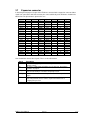
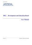
BeMicro User Manual
2009-04-30
1
Overview
The BeMicro FPGA development kit is a cheap and simple development platform for all kinds of FPGA
design in USB stick form factor. It fits into a PC USB host connector port or a USB hub and, thus, is
powered from the PC or the hub. On the stick there is an Altera CycloneIII FPGA for user logic
implementation. An expansion connector allows connecting additional hardware to the FPGA.
2
System description
2.1
Components
The main components on the board are:
•
•
•
•
•
Altera Cyclone III FPGA - EP3C16F256C8N
16 MHz clock oscillator
3 status LED
8 user LED
80-pin edge connector
Two optional components also can be mounted on the board:
•
•
Low power SRAM 256k*16 – Renesas R1LV0416DSB-7LI
Configuration EEPROM – Altera EPCS4SI8N or EPCS16SI8N
Depending on the production lot these optional components may already be mounted onto BeMicro on
delivery.
2.2
Status LED
Nearby the USB connector there are 3 status LED.
Color
red
yellow
green
Meaning
data communication via JTAG port ongoing
FPGA design successfully loaded 2)
power supply enabled 1)
Notes:
1) The power for the FPGA is enabled only if the USB stick is enumerated properly by the PC. In
case the green LED stays off after plugging-in the stick the driver for the stick obviously has not
been installed properly.
2) The yellow LED depends on the CONF_DONE pin of the FPGA.
BeMicro User Manual
Sasco
1/8
2.3
User LED
The 8 user LED are connected to the FPGA and, via current limiting resistor, to VCC. If the FPGA
outputs low level at the appropriate pin then the LED shines. LED[7] is nearest to the USB connector
LED[0] is nearest to the FPGA.
LED
Pin
2.4
7
B1
6
A7
5
B3
4
E6
3
D6
2
C3
1
C2
0
B4
Signal
D14
D12
D10
D8
D6
D4
D2
D0
CS2
UB#
Pin
N6
L6
G5
G1
R1
P1
N1
L2
F2
P3
SRAM (optional)
The SRAM is connected to the FPGA according to the table below:
Signal
A17
A15
A13
A11
A9
A7
A5
A3
A1
OE#
Pin
T3
T4
T5
D1
F3
R7
T7
J1
K1
R6
Signal
A16
A14
A12
A10
A8
A6
A4
A2
A0
WE#
Pin
R4
R5
D3
D5
F1
T6
J2
K2
L3
T2
Signal
D15
D13
D11
D9
D7
D5
D3
D1
CS1#
LB#
Pin
N5
M6
K5
G2
R3
P2
N2
N3
L1
P6
SRAM and FPGA I/O banks are powered from the same 3.3V supply.
The I/O standard for the FPGA pins should be set to 3.3-V LVTTL.
2.5
Clock oscillator
The 16 MHz clock runs permanently if the FPGA power is enabled. The clock oscillator is connected to
the FPGA pin E2. The I/O standard for this FPGA pins should be set to 3.3-V LVTTL.
2.6
Configuration device (optional)
An optional configuration device EPCS4SI8N or EPCS16SI8N can be soldered onto mounting position
U500 (see assembly drawing on page 6). An EPCS16 is needed in case you want to not only store
one hardware image in the configuration device but several images and maybe even software images
as well. Note that the FPGA can access the configuration device only if the boot mode is set to active
serial. This can be done with the solder bridge B400.
1
2
3
Boot mode
passive serial (default)
active serial
In case you want to use the configuration device for storing configuration or other data cut the
connection from pad 1 to pad 2 of the solder bridge and connect pads 2 and pad 3 with some solder.
BeMicro User Manual
Sasco
2/8
2.7
Expansion connector
In total, 64 general purpose I/O pins of the FPGA are connected to the expansion connector. Other
signals are connected as well. All connector pins connected directly to the FPGA are shaded in the
table below. The pin number is given in this case.
Signal
3.3V
RST_N
R12
T13
R13
T14
R14
T15
R16
P14
GND
P16
P15
N16
N15
L16
GND
K15
K16
J16
Conn
1
3
5
7
9
11
13
15
17
19
21
23
25
27
29
31
33
35
37
39
Conn
2
4
6
8
10
12
14
16
18
20
22
24
26
28
30
32
34
36
38
40
Signal
3.3V
PWR_N
T10
R10
GND
T11
R11
N11
N14
N12
GND
M11
L11
L13
L14
GND
L15
K12
J15
J14
Signal
H16
H15
G16
G15
F16
F15
GND
D15
D16
C15
C16
C14
B16
A15
B14
A14
B13
B12
A12
5V
Conn
41
43
45
47
49
51
53
55
57
59
61
63
65
67
69
71
73
75
77
79
Conn
42
44
46
48
50
52
54
56
58
60
62
64
66
68
70
72
74
76
78
80
Signal
J13
GND
J12
G11
F14
F13
GND
E11
E10
D14
D12
A13
C11
C9
B11
A11
B10
GND
EXP
5V
Non-shaded fields denote other signals. These are described below.
Signal
3.3V
5V
RST_N
PWR_N
EXP
GND
Description
This net is a supply output of BeMicro. Up to 200 mA can be drawn
from this source.
The net is a supply input for BeMicro. See chapter 2.9 “Stand-alone
operation” on page 4.
This net is used to reset the application design in the FPGA. The net is
connected to FPGA pin T12 and a 10k pull-up resistor.
Power enable, low-active. See chapter 2.9 “Stand-alone operation” on
page 4.
Expansion board is present. The net is connected to FPGA pin A10
and a 10k pull-down resistor. On the expansion board there is a
stronger pull-up resistor.
Signal and power ground.
BeMicro User Manual
Sasco
3/8
2.8
UART
Two pins of the FPGA are connected to the TxD/RxD pins of the USB controller. This controller and
the corresponding driver DLL allows implementing a virtual UART on the PC. Have a look at the
device manager of your PC. You will find a virtual COM port named “USB Serial Port on BeMicro”.
Data sent out to this COM port is tunneled though the USB channel and, at the end, sent to the FPGA.
The same applies to the reverse communication direction.
Signal
TxD
RxD
2.9
Direction
FPGA to PC
PC to FPGA
Pin
D8
C8
Stand-alone operation
In special cases you may want to run the BeMicro USB stick without a PC. This is possible, though,
some measures have to be taken. First, there are two ways to supply the stick. You can us a USB
power supply that connects to the main USB plug or you can power the stick from the expansion
board. In this case, apply 5V to the VCC net.
In both cases, the USB controller on the stick is not enumerated and therefore, the power regulator
stays off. It must be enabled by some means. In case of the use with expansion board, the PWR_N
signal of the expansion connector can be pulled low, what enables the regulator.
There is a second way to enable the regulator. The solder bridge B600 is used for that.
3
2
1
Power enabled by
signal PWR_N from expansion connector (default)
always
In case you have modified solder bridge B600 you must not plug in the stick into a PC or USB hub any
more.
BeMicro User Manual
Sasco
4/8
3
Installation
It is important to install the software on a PC before plugging-in BeMicro into a USB host connector of
the PC. The complete installation procedure is listed below. It is assumed that Altera Quartus is
already installed on your PC. If not, install Quartus first.
•
•
•
•
•
Download the installation package from the Sasco web site. This package includes the USB
driver, several DLL needed for seamless integration, and some design examples.
Unzip the installation package to a file folder of your choice. Do not use the Quartus Program
folder or a subdirectory for that. Most people use an install folder with several subdirectories
for that. This is the recommend method.
Start the installation program located in <your folder>\programmer\setup.exe.
For details about the installation process read chapter 3.1.
Plug-in BeMicro into a USB host connector of your PC.
Tell Windows where to find the USB driver. This is <your folder>\driver.
By installing the software onto your PC you are bound to the license agreement of the Arrow
USB-Blaster software. The complete license agreement can be found in chapter 5, License
Agreement on page 7. This license agreement, in short, allows you to use the software only in
conjunction with Altera FPGA purchased or obtained in any other legal way from Arrow or a subsidiary
of Arrow.
For FPGA designs without embedded CPU as well as for NIOS based FPGA designs this basic install
is all you have to do. Other CPU architectures may require additional install steps.
3.1
Setup.exe
You need administrator rights in order to run the setup program for BeMicro. This program executes all
tasks needed to install and register the programmer hardware DLL. It asks where to store these files.
Since the programmer hardware DLL can be used with different release versions of Altera Quartus it is
recommended to store the DLL in the Altera root program folder. This is that location where several
folders for different release versions of Altera Quartus might exist.
BeMicro User Manual
Sasco
5/8
4
Assembly drawing
The picture below shows the mounting positions for the components. The RAM (U501) and the
configuration EEPROM (U500) are crossed out since these components are optional. In case these
two components are missing on your BeMicro stick you can add them on your own.
BeMicro User Manual
Sasco
6/8
5
License Agreement
This Source Code License Agreement (this “Agreement”) is made and effective as of the installation of
the software by and between the user “Licensee” and Arrow Electronics, Inc “Arrow”. Licensee and
Arrow may be referred to individually as a “Party” or collectively as “Parties,” as the situation may
require. “Arrow” also includes all subsidiary companies of Arrow Electronics, Inc.
WHEREAS, Licensee desires to obtain, and Arrow is willing to grant to Licensee, a license to use, on
the terms outlined in this Agreement, the executable code of the Arrow USB Blaster DLL and the
associated documentation files (the “Software”).
NOW, THERFORE, in consideration of the following mutual promises herein, the Parties agree as
follows:
1. Subject to the terms and conditions of this Agreement, Arrow grants, free of charge, to Licensee a
non-exclusive, perpetual, royalty-free, and world-wide license to use the Software for use with Altera
devices legally obtained from Arrow only. Such use shall include the right to copy the Software or
distribute or sell products incorporating the Software for use with Altera devices legally obtained from
Arrow only. Licensee shall have the right to sublicense the foregoing rights subject to the terms of this
Agreement. LICENSEE IS EXPRESSLY PROHIBITED FROM USING, AND SHALL PROHIBIT ANY
PERMITTED SUBLICENSEES FROM USING, THE SOFTWARE TO PROGRAM PROGRAMMABLE
LOGIC DEVICES, FIELD PROGRAMMABLE GATE ARRAYS, APPLICATION SPECIFIC
INTEGRATED CIRCUITS, APPLICATION SPECIFIC STANDARD PRODUCTS, OR ANY OTHER
INTEGRATED CIRCUIT PRODUCTS DESIGNED OR MANUFACTURED BY ANY COMPANY OR
ENTITY OTHER THAN ALTERA OR OBTAINED FROM ANY COMPANY OR ENTITY OTHER THAN
ARROW.
3. THE SOFTWARE IS PROVIDED “AS IS”, WITHOUT WARRANTIES, REPRESENTATIONS, OR
GUARANTEES OF ANY KIND, EXPRESS OR IMPLIED, INCLUDING BUT NOT LIMITED TO THE
WARRANTIES OF MERCHANTABILITY, FITNESS FOR A PARTICULAR PURPOSE, TITLE, AND
NONINFRINGEMENT. IN NO EVENT SHALL ARROW BE LIABLE UNDER ANY LEGAL THEORY,
WHETHER IN AN ACTION OF CONTRACT, TORT, OR OTHERWISE, FOR ANY CLAIM,
DAMAGES, OR OTHER LIABILITY, ARISING FROM, OUT OF, OR IN CONNECTION WITH THE
SOFTWARE OR THE USE OF OR OTHER DEALINGS IN THE SOFTWARE.
4. THIS SOFTWARE IS PROVIDED WITHOUT MAINTENANCE OR SUPPORT OF ANY KIND. IN
NO EVENT SHALL ARROW BE LIABLE FOR ANY MAINTENANCE, SUPPORT, SERVICING,
REPAIR, OR CORRECTION OF THE SOFTWARE. IN NO EVENT SHALL ARROW BE LIABLE FOR
ANY INDEMNFICATION OBLIGATION IN CONNECTION WITH LICENSEE’S USE OF THE
SOFTWARE.
5. In no event shall the aggregate liability of Arrow relating to this Agreement or the subject matter
hereof under any legal theory (whether in tort, contract, or otherwise), including any liability for any
loss or damages directly or indirectly suffered by Licensee relating to the Software, exceed the lesser
of (a) the aggregate amount of the license fees actually paid by Licensee under this Agreement or (b)
Ten Thousand U.S. Dollars (USD$10,000). IN NO EVENT SHALL ARROW BE LIABLE UNDER ANY
LEGAL THEORY, WHETHER IN TORT, CONTRACT, OR OTHERWISE (a) FOR ANY LOST
PROFITS, LOST REVENUE, OR LOST OR INTERRUPTION OF BUSINESS, (b) FOR ANY LOSS OF
OR DAMAGES TO OTHER SOFTWARE OR DATA, OR (c) FOR ANY INCIDENTAL, INDIRECT,
CONSEQUENTIAL, OR SPECIAL DAMAGES RELATING TO THIS AGREEMENT OR THE
SUBJECT MATTER HEREOF, INCLUDING BUT NOT LIMITED TO THE USE, SUPPORT,
OPERATION, OR FAILURE OF THE LICENSED SOFTWARE, WHETHER OR NOT FORESEEABLE
AND EVEN IF ARROW HAS BEEN ADVISED OF THE POSSIBILITY OF SUCH LIABILITY AND
DAMAGES.
6. This Agreement shall be governed in all respects by the laws of the State of New York and by the
laws of the United States of America, without regard to its conflict of law or choice of law principles.
7. Arrow expressly does not recommend, suggest, or require that the Software be used in conjunction
or combination with any other product. IN WITNESS WHEREOF, Licensee and Arrow hereby enter
into this Agreement and have caused this Agreement to be executed by their respective duly
authorized representatives as of the Effective Date.
BeMicro User Manual
Sasco
7/8
6
Additional remarks
The Altera USB Blaster and BeMicro both use an USB controller from FTDI that use the same
communication driver DLL. Communication issues might occur if an USB Blaster and a BeMicro are
connected to the same PC at the same time. So, it’s advisable to only use one of these devices at one
time.
7
Document history
2009-02-19: Draft
2009-03-06: More details about the usage of the installation program setup.exe
BeMicro User Manual
Sasco
8/8