1
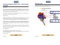
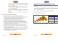
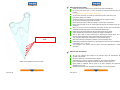
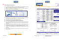
REV: E03.14 1 REV: E03.14 2 REV: E03.14 79 IIN ND DEEX X INDEX .........................................................................................................................................1 INDEX .........................................................................................................................................3 INTRODUCTION.........................................................................................................................4 SPECIFIED OF WORKS.............................................................................................................5 LOCATION OF MODEL ..............................................................................................................6 WARNING LABEL.......................................................................................................................7 GUARANTEE ..............................................................................................................................8 CE DECLARATION SHEET FOLLOWING DIRECTIVE 2006/42/CE.......................................10 PREVENTATIVE RULES ..........................................................................................................11 HYDRAULIC VIBRORIPPER STRUCTURE.............................................................................27 FUNCTION OF EACH PART ....................................................................................................28 TECHNICAL FEATURES..........................................................................................................29 MEASURE FEATURES ............................................................................................................30 HYDRAULIC VIBRORIPPER INSTALATION ...........................................................................31 WORKING WITH THE VIBRORIPPER.....................................................................................33 PRECAUTIONS DURING THE OPERATION...........................................................................37 STOP OF THE VIBRORIPPER.................................................................................................41 MAINTENANCE ........................................................................................................................42 CHANGING THE TOOL (RIPPER TOOL) ................................................................................45 TORQUE FORCE .....................................................................................................................46 CHARGING PNEUMATIC DAMPER WITH N2.........................................................................47 GEAR BOX LUBRICANT ..........................................................................................................49 UNDERWATER WORKS ..........................................................................................................52 WEARING OF GEAR BOX AND MOTOR SEAL. .....................................................................53 INSTALLATION PROBLEMS....................................................................................................54 MALFUNCTIONS DURING SERVICE ......................................................................................56 ACCESSORIES THAT MUST ACCOMPANY THE HYDRAULIC VIBRORIPPER ...................60 SELECTION OF RIPPER-TOOL...............................................................................................61 RIPPER TOOL WITH INTERCHANGEABLE TOOTH ..............................................................65 RECOVERY DAMAGED RIPPER TOOLS – TOOTH HOLDER WELDABLE ..........................74 OTHER ATACHMENTS (OPTIONAL) ......................................................................................77 REV: E03.14 78 REV: E03.14 3 IIN NTTR RO OD DU UCCTTIIO ON N O OTTH HEER RA ATTA ACCH HM MEEN NTTSS ((O OPPTTIIO ON NA ALL)) After you have made the right decision of purchasing a VIBRORIPPER SIHAM MULTIFUNCION • COMPACTOR PLATE • POST DRIVER • VIBROHAMMER – SHEET PILE to serious injury, by this way the user will be responsible to mind the security guidelines. • RAIL DRIVER The objective of this manual is: • … TABE, which is the result of our experience, technique control and quality of raw materials, please read this manual carefully before you start to work with the hydraulic hammer. Thus you will know better your equipment and you will prevent malfunction and failure due to an inadequate use of the equipment. Look carefully the security guidelines that you can see in this manual, knowing that if the vibroripper is used carelessly, an accident can occur, leading • To describe the correct usage of the Vibroripper. • To prevent distress. • Maintenance and inspection guide. • Support to detect failures. The security guidelines are according with the regulations of the country where the Vibroripper is used. The vibroripper should not be used for any work other than the specified works. Keep the manual near the machine and if the Vibroripper is transferred, be sure to attach the manual. From TABE we can develop that attachment that may be necessary for our clients, and vibration needed for implementation. Contact us! REV: E03.14 4 REV: E03.14 77 SSPPEECCIIFFIIEED DO OFF W WO OR RK KSS STEP 2: INSTALL THE The TABE Hydraulic Vibroripper range must be install in hydraulic excavators in pursuance of TOOTH the relationship between the excavator weight and the vibroripper weight, with the special HOLDER purpose to achieve largest operation ratio and to prevent accidents. Place the the tooth holder above the The different types of work, which a hydraulic vibroripper can be subject, are the following: one prepared, as the drawing for each * Foundation. model. There must be a distance of 3 mm / 0.12 inches between the tooth holder and the ripper arm. If welding lengths are slightly different, the front * Demolition. * Scarification. * Ditching. * Scaling. * Breaking work. * Dismantling * Opening of block. lines must match. Welding alternately on both sides to correct deformities. Grind ripper longitudinally, using a fine grained grinding wheel, avoiding crosswise stripes ripper. Upon completion, leave a thickness of over-welding and grind it so that it is smooth and flush surface. When complete, check for cracks. If any, clean and re-weld the affected area. Vibroripper in action. REV: E03.14 76 REV: E03.14 5 LLO OCCA ATTIIO ON NO OFF M MO OD DEELL ASME / AWS: E 70 T1 (rutile cored wire) ASME / AWS: E 70 T5 (basic cored high mechanical) The model name is stamped on the top of protective housing and the serial number is stamped on the EC label for D group, where it is specified: 1. Manufacturer (name and address). 2. Manufacturing year. 3. Identification number. 4. Weight. 5. Manufacturer designation. DIN SG B1 C 5254 (DIN 8559) Use gas mixture AR + 25% CO2. Specify that can not have any humidity. The recommended minimum flow is 16.52 l / m. The serial number and the model name are necessary when placing an order of parts, asking for repair or if the vibroripper is transferred. STEP 1: PREPARE DAMAGED RIPPER TOOL Cut using saw, avoiding use the torch to heat not to affect the material, along the plane indicated for each model. Prepare chamfers for welding. Must be EC label for D group. The majority pieces of the model are stamped with a relation numbers of that model, to 35 º as indicated by the drawings. As an example the ripper tool should look like this: maintain the genuineness of TABE. REV: E03.14 6 REV: E03.14 75 R REECCO OV VEER RY YD DA AM MA AG GEED DR RIIPPPPEER OTTH HH HO OLLD DEER R TTO OO OLLSS –– TTO OO R W E L D A B L E WELDABLE W WA AR RN NIIN NG G LLA AB BEELL The hydraulic vibrorippers show warning labels to prevent mistakes and accidents during the inspection and maintenance; the labels are the following: DESCRIPTION: 1. Discharge N2 before disassembly. After some hours the ripper tool can be damaged. In this section we will see how to retrieve a 2. Do not stand near the working zone. ripper tool that had no tooth and make it an interchangeable teeth ripper tool, or how to 3. P (pressure). retrieve a riiper tool with interchangeable tooth that does not allow a new tooth due to 4. R (return and Drain). deformations and continuous chamfered with grinder. You can buy a new ripper tool, so the change will be very fast or may purchase only a weldable tooth holder and make a recovery process. GENERAL RULES: Cleaning is recommended prior in the bonding surfaces, removing paint, grease, rust or other foreign materials. The presence of hydrogen containing contaminants (grease, paint, or organic matter) may cause a premature failure. Use a wire brush or apply a light grinding. Preheat at 140-180 ° C the weld area. Use a gas torch. Prolonging the heating, without exceeding the limits given until the area keep the temperature indicated. If for any reason the process is interrupted and welding is not posible to maintain the preheat, restart again the preheat process. During the welding process. Not exceed, outside the areas directly affected by the welding temperaturas, above 250 ° C. Space the welding times to maintain the temperature within the preheating and maximum temperature. WELDING MATERIAL: Use cored wire (Flux-core) with low hydrogen content certificate. Recommended Maximum diameter: 2.4 mm / 0.09 inches. Attending to the recommendations given by the manufacturer. Cored preferred: REV: E03.14 74 REV: E03.14 7 G GU UA AR RA AN NTTEEEE VERY IMPORTANT NOTE: TABE hydraulic vibroripper is guaranteed: “12” months: breakage not wearing. The following components are not under guarantee: TOOL (nail and rest of implements), HOSES, SECURITY PIN, PNEUMATIC DAMPER. When placing a new tooth, you must retighten the bolts, after about 5 or 10 minutes of work. You have to repeat this as many times as necessary until the tooth is completely attached to the tooth holder. Guarantee begins the moment the breaker is delivered to the customer. This date will be included in “GUARANTEE SHEET” as well as the vibroripper’s working parameters. This GUARANTEE sheet must be filled up and signed by TALLERES BETOÑO S.A. or an Repeat whenever you feel the tooth has a gap with the tooth holder. NOT DOING SO will damage the tooth holder completely and the tooth may shatter or crack. authorised dealer. The receipt of the “GUARANTEE SHEET” in TABE enables the guarantee period. Thoroughly clean the locking caps that blocks the screws, so that those caps could make perfectly face to face. TABE’s responsabilty is limited to the defaults which occur to the products only if they have been used in the conditions for which they were designed and whenever they have been used following the operating instructions and the status of the vibroripper has not suffered any modification. NOTE: Extreme clean and lightly lubricate parts when inserting a new tooth. The replacement of any part during the guarantee period does not extend the guarantee period of this part The parts replaced free of charge will remain under TABE’s property Transportation costs of spare parts under guarantee and after-sales assistance staff’s expenses will be at customer´s charge. REV: E03.14 8 REV: E03.14 73 Important recommendations: Model. When placing a new tooth, tighten the retaining bolt until the tooth not present any clearance Nº or clearances are minimal. You can verify this by applying a levering motion of the tooth on the tooth holder. Date of delivery OIL FLOW 27/01/2012 27/01/2013 OIL Pressure Company / Customer Address Technical Assistance Service Parts guarantee conditions: • To place the locking caps is necessary that the faces of the clamping screws are parallel as The TABE original parts are covered by 3-months and until the end of the guarantee for a new hydraulic vibroripper. shown in the figure. IMPORTANT: TABE is not on charge of any guarantee if the customer has used other parts different to TABE original parts. REV: E03.14 72 REV: E03.14 9 CCEE D DEECCLLA AR RA ATTIIO VEE ON N SSH HEEEETT FFO OLLLLO OW WIIN NG G D DIIR REECCTTIIV 22000066//4422//CCEE EC-DECLARATION OF COMPLIANCE Chamfers The manufacturer TALLERES BETOÑO S.A. With address at Becolarra, 8 P.I. Ali - Gobeo 01010 Vitoria SPAIN Declare: REPLACEMENT TOOTH HOLDER: The machine described below: Type of machine: Hydraulic Vibroripper Trademark: Function: TABE Rupture of materials such as concrete, asphalt, With the passing of time, once changed several teeth, the nose will have already a considerable wear, so it will be necessary to replaced it with a new one. To do this job, please contact your local dealer of TABE products. Model: The time to change for a new tooth holder comes when the bolt retainer can not tighten the Serial Number: Weight: tooth against the tooth holder to correct clearances. Kg Complies with all applicable provisions of the Machinery Directive (Directive 2006/42/EC) and National Regulations which transpose (transposed by Royal Decree 1644 / 2008) Quality management system certified by the norm: UNE - EN ISO 9001: 2008 It also complies with all applicable provisions of the following Community Directive: - Directive 2000/14/EC noise emission and national regulations which transpose (Norm UNE - EN ISO 3744: 1996) Organization Certifier "AAC S.L." (Accredited ENAC 88/LE229) The data of the person empowered to develop / to save this file: “NAME” CORRECT WRONG After-Sales Service Manager Sig.: “Name” DATE: REV: E03.14 10 REV: E03.14 71 During normal operation, small relative movements between the two parts can generate high temperatures, so that the surface treatment of both pieces will degrade and lose hardness. This loss of hardness can deform the tooth holder, causing it to fill these gaps. This can make it difficult to remove tooth. Never hit the tooth directly. Help yourself with a hammer and tap firmly on the ends as shown: PPR REEV VEEN NTTA ATTIIV VEE R RU ULLEESS BEFORE OPERATION Read the manual: To know you equipment and to prevent malfunction and failure or severe injury owing an inadequate use of the equipment, you must read the excavator instruction manual and the hydraulic vibroripper instruction manual. Keep the manual close to your hydraulic excavator, and do not operate the machine until you fully understand all these items. Protective equipment: Depend of the operation that you have to do Once you have managed to remove the tooth, you should check the state of the tooth holder. NOTE: The deformations in the tooth holder are normal, because of the equipment's work. His recovery is not covered under warranty. Typically, after removing a tooth you should make a repair job to restore the original shape of the tooth holder. Chamfers mainly to allow a new tooth be inserted without interference. For this process you should need the help of a grinder. REV: E03.14 70 (maintenance, repair, control) you must wear safety boots, safety glasses, breathing mask, gloves or ear protection if the sound level exceed 85 dB (A). Do not wear loose clothes that can become entangled in the machinery and by the way minimise risks. Do not wear clothes soaked with oil to prevent fire hazard. REV: E03.14 11 Step 5: Remove the tooth. Others protective and security measures: Be sure a first aid kit and fire extinguisher are on the hydraulic excavator. Do not allow personnel around the work area (radio: 7 metres.). Do not operate the machine if you have taken in alcohol or drugs. When operating the hydraulic vibroripper in a work site that is potentially dangerous because of Problems when removing the tooth: falling rocks, install a head guard on the hydraulic excavator. The tooth is a piece of cast steel, and therefore, accuracy and in the finish of these parts, there are some inevitable dimensional differences between the same model teeth. Not all Vibroripper – Excavator ganging: teeth are dimensionally accurate. Depend of the hydraulic vibroripper’s weight, this one will be install to determined excavator. Thus, between the tooth holder and tooth there are gaps. These clearances are corrected The relationship between both variables is very important: if the excavator is too small it is through the tensioning system, but between the two parts may be gaps. possible to tip over; and in the other way, the vibroripper’s period of life would be short. VIBRORIPPER RANGE EXCAVATOR WEIGHT TYR2 2–4T TYR8 8 – 12 T TYR12 12 – 17 T TYR15 18 – 24 T TYR25 24 – 31 T TYR35 – TYR40 30 – 40 T TYR45 – TYR50 40 – 54 T TYR55-TYR60 50 – 65 T TYR90 70-100 T Relationship between vibroripper – excavator. REV: E03.14 12 REV: E03.14 69 Step 3: Unscrew the clamping screws and remove them along with their washers. Vibroripper – Excavator hydraulic coupling: The hydraulic installation must keep the diameter requirements for the pressure (P) and return (R) hoses. Very important to prevent leakage is to fit and replace, if is necessary, the hexagon part of the hose. This part must be clean. The temperature, pressure, revolutions and the oil flow between the vibroripper and the hydraulic excavator are different. If the pressure and oil flow exceed their available range, they can lead to increased vibrations, shocks and hose movements, and the hydraulic vibroripper and the hose can become damaged. Serious injury or death can result from it. You must adjust the oil pressure and flow correctly between Step 4: Remove the pin stopper. the hydraulic vibroripper and PRESSURE LINE the excavator to provide a satisfactory range of work. Inspect the equipment: Before you start to work, you must perform inspection of the equipment to prevent malfunctions. You must inspect hoses bolts, nuts and pins using the protective equipment. Check if the pins have the safety pin. If you have to replace any pin or to change the hydraulic vibroripper, be sure to replace it on flat ground to prevent from accidents. If any hose is damaged or loosed can burst open and blow out hydraulic oil during operation, and serious injury or death can result from it. REV: E03.14 68 REV: E03.14 13 Step 2: Remove the Locking caps. Changing the tool (ripper tool): If you use a wasted ripper tool, broken or damaged rota o serious injury, death or accidents can result from it. Other security rules before operating with the vibroripper: Know the safety instructions in the safety and health plan of the work to carry out work with this type of machine. Reported every day from other work that may create hazards (holes, ditches, etc..), The simultaneous implementation of other state jobs and work environment (slope, obstacles, ice, etc.) Know the workplace or work where the machine moves. Especially, the terrain, the points where there may be restrictions on height, width, weight and presence of overhead power lines. Follow traffic rules established in the area of the site and, in general, marked on the Highway Code. If necessary, place the appropriate safeguards regarding pedestrian circulation area, workers or vehicles (fences, signs, etc.). The machine must be registered to travel on public roads and should have the mandatory safety and signaling elements (rotating light, mirrors, etc.). To move within the play is recommended that the driver has at least Class B driver's license. When driving on public roads, the driver must necessarily possess it. Only the machine can work indoors (inside buildings, tunnels, etc..) Where it can ensure to maintain adequate ventilation and sufficient for job performance. In this case you must stop the engine when the machine is not used. Never use the machine in potentially explosive atmospheres (about storage of flammable materials like paint, fuel, etc.). Avoid drive and work near the edges of excavations, ditches, embankments or slopes. If necessary, the machine must have a rollover protective structure (ROPS). The edges of excavations and casts must be enclosed and have elements to warn the operator that is closing over it. The cockpit must be equipped with a protective screen in the front to prevent the projection of objects. When they carry out demolition work where there may be a risk of objects falling on the driving position, the machine must have a protective structure (FOPS). REV: E03.14 14 REV: E03.14 67 When there is dusty environment in the workplace, following the movement of other Tooth holder vehicles or the work itself, and the machine does not have a closed cabin, soak the area previously, so as to avoid dust, but without producing sludge. Check on the health and safety plan the possible existence of overhead power lines and Tooth gable or service pipes buried in the ground (electrical cables, gas, water, sewage, etc.). Learning about preventive measures to avoid contact with such lines or ducts (standard, protection, signaling, etc.). Maintain the following distance limits of approach to the electric airlines: at least 3 meters for voltages up to 66kV, a minimum of 5 meters for voltages between 66kV and 220kV, and at least 7 meters for voltages of 380kV. Knowing the precise location and depth of underground pipes (water pipes, gas, sewerage and electrical wires). If it is not possible to know the exact location of Tensioner System underground pipes and electricity or gas, should be used metal detection equipment to locate it. When natural light is insufficient, you must paralyze the work if the machine does not have its own lighting system or if there is no artificial lighting to ensure adequate visibility. TOOTH CHANGE: Stop work when conditions are adverse weather (fog, rain, etc.). Step 1: Remove the locking screws of the Tensioner system. You will need an Allen wrench. When choosing a vibroripper should take into account a number of factors to make it suitable for both carrier and for the work to be performed: number of revolutions per minute, impact energy, pressure and working flow. Respect ratio vibroripper weight - weight carrier provided by the manufacturer (usually you can go from 1:10 to 1:20). Check the stability of the whole system before starting work. The assembly and disassembly of vibroripper should be done on a firm, level ground. The vibroripper should be placed horizontally on a block to facilitate placement and removal of the pins. Verify that there is no pressure in the hoses before disconnecting. Use a soft hammer or punch ejector to the input or output pin. Use safety glasses and gloves suppression during the operation. Work clothes with adjustable cuffs. It is not recommended to wear pendants, chains, loose clothing, etc. that could become entangled with elements of the machine. It must use the safety equipment listed in the Health and Safety Plan for the issues mentioned in it. Below is an example of equipment that can be used: o Safety shoes: Its use is mandatory in a play. Anti-holes must have nonslip soles. REV: E03.14 66 REV: E03.14 15 o Protective helmet: It should be used when the machine is not available or when the protective roof of the cabin down there is a risk of falling objects or head injuries. o Safety glasses: should be used when the cockpit windshield and has no risk of splashing exists in the eye. o Hearing protectors: It is mandatory when the value of exposure to noise (LAeq, d) exceeds 87 dB (A). o Gloves: are recommended for control operations in the state of the machine and for the maintenance described in the user manual vibroripper. o Clothing or a reflective vest, will be required to work where other vehicles nearby. R OO OTTH H RIIPPPPEER R TTO OO OLL W WIITTH H IIN NTTEER RCCH HA AN NG GEEA AB BLLEE TTO DESCRIPTION: In certain very abrasive rocks conventional nail ripper will suffer a considerable wear in a short time of use due to abrasion against rock. For these types of rock we recommend using a ripper tool with interchangeable tooth. This tooth is made of cast steel and has a hardness greater than 500 Brinell. These teeth are available for all TABE models: Daily checks before operating the vibroripper: Check that the machine has no obvious structural damage or fluid leaks. Make sure all screws are tight vibroripper and verify that the hose connections are in perfect condition and are properly attached to vibroripper and machine. Ensure that light and sound devices are in good condition and fully operational. If available, check the tire pressure and that no cuts in the tread. Make sure the ripper tool is sharp and no fractures, chips or excessive wear. Keep vibration box’s bearings lubricated (approximately every 2 to 3 working days). Check the status and adjustment of mirrors and keep clean the windshield of the cabin. Check that the seat belts and their anchorages are in good condition and adjust the seat that is appropriate to weight and size of the operator. Check that the levels of fuel, hydraulic oil and motor oil are adequate. Fill if necessary. Keep driving seat, footrests and handholds clean and free from oil, grease, mud, ice. Maintain the cockpit free of objects or tools that can move freely preventing the Check that the information and warning signals remain clean and in good condition. Disassemble the vibroripper be done by the authorized service, but it is very important to download the balloon tire with nitrogen gas prior to the disassembly of vibroripper. Check that the pneumatic damper has pressure. REV: E03.14 16 Weigh of the tooth (Kg) TYR – 8 / 12 / 15 14 TYR – 25 / 35 / 40 21.8 TYR – 45 / 50 / 55 / 60 52.3 TYR – 90 / 120 106 The appearance of the tooth holder + tooth assembly has the following form: realization of a particular maneuver. Vibroripper Model: REV: E03.14 65 When starting the machine. Getting on and off the machine by the pertinent front steps and handholds. Do not use arms control and / or levers as handles for raising and lowering from the machine. Do not jump off the machine except in an emergency. You must carry and keep your hands dry and clean the soles of mud and / or fat. Once seated, fasten your seatbelt. The machine should only be started and operated from the operator's position. Do not remove any body parts outside the cockpit. Before starting the engine, check that nobody is in the range of the machine. Ensure at all times that no one can remain within the range of the machine during use or movement. When you can not avoid the simultaneous performance of other work, with operations outside the machine itself, there must be coordination between jobs. Before starting the engine check that all levers and controls are in neutral. Follow manufacturer's instructions for starting the engine of the machine. Once in place, check its proper functioning by observing the indicator lights. The oil It can be sharpened many times pressure gauges and battery must be switched off when the engine runs. Then, using slow maneuvers, check that all controls respond properly. Begin work when the oil temperature reaches its normal operating value. Check that the hydraulic oil temperature is kept within the limits set by the manufacturer of vibroripper. (40 º C - 80 º C). The vibroripper must operate with the engine revolutions established for specific vibroripper. When moving the machine. You can only transport other people on the machine where the manufacturer has provided a second seat. No person shall carry on the brackets of the machine. Models 70 and 70AMP can have up to 5 lifes. Preferably drive by ways or land firmly in place, dry, clean and free of obstacles. Keep a safe distance to the edges of excavations, ditches, uneven terrain, etc. Adjust speed to conditions and the state of the land, respecting the speed limit established in the work. Avoid abrupt maneuvers such as braking, accelerations, or turns at high speed. REV: E03.14 64 REV: E03.14 17 Always keep a safe distance when driving near other machines. Use extreme caution at intersections with poor visibility. Type of rock Always follow the light path of the machine. Ripper tool Before reversing the direction of travel, ensure that sufficient space is available and there are no trenches, holes, objects, people, etc… Level of abrasion If the machine has reversing beeper, hold on while you are working with the machine inside the work. To travel on public streets should be disconnected. If not available, you must activate the horn before starting a reversing maneuver. If available, during the movement should be kept locked device rotation of the superstructure and foot orientation of the pen. The vibroripper collected should remain on the machine during transport. Avoid turning up or down curbs. If necessary, sloping ramps should be placed low to be of a material capable of withstanding the weight of the machine. Non abrasive rock Medium abrasive rock Fragility of the rock Very abrasive rock X Very soft rock Medium rock REF Very hard rock X X X Use extreme caution when driving on steep slopes. Always choose dry roads and with adhesion. Never approach slope unbound. X X Keep a safe distance from their side edges. Never travel in the direction perpendicular to the slope. X Never travel on slopes greater than those recommended by the manufacturer. X 70 70 D 70 NS+D O P P O P P Vibroripper is not recommended Use Hydraulic Breaker. P O O P O O WARNING! The recommended slope does not mean you can maneuver safely in the same at any load condition, land or maneuver. X X When driving on slopes always have it up or down, avoiding the performance of turns. Going up or down a slope shall be kept vibroripper extended and faces the ground, with X one located approximately 20 to 30 cm. soil. Thus, in case of loss of stability of the X machine, you can download the vibroripper immediately to the ground to act as a brake. X X Vibroripper is not recommended Use Hydraulic Breaker. P O O P O O When working with the machine. X Knowing the type and content of the site or material on which you intend to use the X vibroripper. Do not work very resistant surfaces or may lose its strength during labour vibroripper. X X As a general rule, in the presence of buried pipes can only use this machine up to 1 meter driving. Between 1 meter and 50 cm. Power tools should be used. Below 50cm. The approach will be done manually. Check that no objects can fall from heights caused by the work itself vibroripper. REV: E03.14 18 REV: E03.14 63 Vibroripper is not recommended Use Hydraulic Breaker. Temperature: If the machine has a cab, keep it closed during use. If not available, whenever possible In not very fragile rocks, the ripper will need more time for penetration. That means if we work upwind, so that it can not be diminished visibility. have two pieces in that area (tooth and tooth holder), the relative movements between them Do not allow the presence of other workers in the working area of the vibroripper and, if will generate a very high temperature (Over 500ºC). With that temperature the heat treatment available of the superstructure, its turning area. of the two pieces involved will get damaged, and hardness in the two pieces will decrease. When needed the help of a signer, should be established by mutual agreement signals Without hardness in these pieces a premature wear will appear. After 5 o 6 changes of the for indicating turning, lifting, etc. He must be located where clearly visible from the tooth the tooth holder will be damaged and it will be necessary to replace it. Also when the cockpit and as far as possible the range of the machine. wear appears the retainer will be lost frequently. Once you have located the machine in the place of work desired, apply the parking Also these high temperatures will damaged the plastic pieces of the retainer. brake, put the knobs and levers in neutral position and deploy the stabilizers to level the machine. Choosing the right tool depends in these two parameters (abrasion and temperature): Never work with boom oriented perpendicular to the chassis of the carrier. Press firmly the vibroripper on the ground by moving the boom. Never allow the machine to raise the vibroripper supported. Do not hit the vibroripper abruptly into the ground. O: Optimal A: Available -: Not recommended Do not work with the cylinders of the boom, dipper and the hammer fully extended or collected. Will damage the stems and packings. Turn the vibration careful to keep the force exerted on the ripper tool. No vibrate in more than 120 seconds at a time. If necessary, change the point of ripping. Immediately stop the vibration when breaking the material. Do not allow the ripper tool cross through the material and work in the air. To work on or under water, mud, etc…, adequate vibrorippers must be used. The TABE vibrorippers can make this work. No lifting or carrying loads with vibroripper. Do not demolish the elements located above the vehicle carrying the vibroripper. Do not move rocks with the vibroripper body. It is allowed dig or make lever movements when the ripper tool is driven into the ground. Hearing protectors: It is mandatory when the value of exposure to noise (LAeq, d) exceeds 85 dB (A). REV: E03.14 62 REV: E03.14 19 SSEELLEECCTTIIO ON NO OFF R RIIPPPPEER R--TTO OO OLL DURING OPERATION DIFERENT RIPPER TOOLS FOR DIFERENTS MATERIALS: Protective equipment: We have developed different tools to cover all the possibilities that the end user could need: When operating the hydraulic vibroripper with a hydraulic excavator fastening safety belts is recommended to minimise the possible risks of injuries. Do not must forget to use ear protection if the noise level exceed 87 dB (A) REF: -70 REF: -70D REF:-70NS+D Material: HARDOX400 Material: HARDOX400 Tooth: Steel with a medium-low Mn-Cr-Mo-Si content. Web: 38-41 HRc Tooth: 48-52 HRc Advantages: Tooth can be replaced. Ideal for very abrasive soft rocks. Cost of the tooth is lower than a complete ripper tool. Once is finished it can be modified to reference 70NS+D Material: HARDOX400 Tooth: Steel with a medium-low Mn-Cr-Mo-Si content. Web: 38-41 HRc Tooth: 48-52 HRc Advantages: Tooth can be replaced. Ideal for very abrasive soft rocks. Cost of the tooth is lower than a complete ripper tool. Cost of the tooth holder is lower than a complete ripper tool. Once is finished it can be modified to reference 70NS+D Disadvantages: Sort life in very hard rocks. Possible problems with tooth holder and retainer in hard rocks. After 5 or 6 changes the tooth holder must be replaced. Disadvantages: Sort life in very hard rocks. Possible problems with tooth holder and retainer in hard rocks. After 5 or 6 changes the tooth holder must be replaced. 38-41 HRc Hydraulic vibroripper customs: The hydraulic vibroripper must be used to the specified works in the part Types of Works A load hanging or load pushing from the hydraulic vibroripper may fall and cause serious injuries or property damage. Never suspend or place any objects on the hydraulic vibroripper. Advantages: Very long life for non abrasive rocks. It can be sharpened many times. Once is finished it can be modified to reference 70NS+D Excavator – vibroripper operations: When you are working with the hydraulic excavator and the hydraulic vibroripper, first you must read and understand the instructions manual for your particular hydraulic excavator. Do not Disadvantages: Sort life in very abrasive rocks operate the machine until you fully understand all these items. The problems of the different rocks: Abrasion: The more abrasive is the rock, the tool will suffer more wear. Therefore the tool life will be shortened. That is why we need to use in abrasive rocks, tools with more surface hardness to reach to a better performance from wear. REV: E03.14 20 REV: E03.14 61 A TTH M ACCCCEESSSSO OR RIIEESS HA ATT MU USSTT H Y D R A U L I C V I B R O R I P P E R HYDRAULIC VIBRORIPPER A ACCCCO OM MPPA AN NY Y TTH HEE Hot areas: During the operation the vibroripper is hot, and right after stopping the machine is still hot and contacting the tool, housing or the hydraulic oil can cause serious injury. • CE Declaration sheet. • Guarantee sheets. • Instructions book. • Fixed keys. • Pneumatic damper charging kit. Trouble procedure: If any part of the hydraulic vibroripper is broken or you can hear any strange noise, stop the operation and repair immediately. In the case of any part of the hydraulic vibroripper is leaking oil, stop the operation and repair immediately Do not must work until the hydraulic vibroripper is repaired, in the other way the risks of accidents and properties damages will increase. Precautions during the operation: When you are working with a hydraulic vibroripper coupled to hydraulic excavator you must have special attention to: REV: E03.14 60 • High voltage line. • Water pipes. • Gas pipes. • Fiber optic cable. REV: E03.14 21 When finishing the work. • Never leave the driving position without being stopped before the engine. • Support vibroripper on the floor even during outages of short duration. • Do not touch the ripper tool immediately after finishing the job. Wait a reasonable ACCUMULATOR/PNEUMATIC DAMPER DISCHARGED time until it has cooled. • At the end of the work, park the machine on a level surface and tough as possible, • Excessive vibrations in cabin and excavator’s boom. • The upper levers touch the housing. • Sound level increases. out of the way the way to other vehicles or people. • If parking on a slope, orient the machine to the top of the slope and support the CAUSES vibroripper on the ground have the boom extended. • • As a general rule, do not park the machine within 3 meters from the edge of excavations or the like. • SOLUTIONS • Damper discharged or broken • Once parked, vibroripper support on the ground by applying slight downward Put all the knobs and levers in neutral position and operate the parking brake. • If available, lock the device rotation of the superstructure. • Follow manufacturer's instructions to stop the motor of the machine. • Remove the ignition key to prevent use by unauthorized personnel. ROADWAY TRANSFER: Load the vibroripper: The hydraulic vibroripper must be load using a crane in the specified area for this job: the housing. Transport holes REV: E03.14 22 Charge the pneumatic damper to the correct pressure level. pressure. • Verify pneumatic damper. REV: E03.14 59 Plug the vibroripper: OIL LEAKAGE If oil leaks from the hydraulic vibroripper during transporting, oil may drop on a road and cause accidents, or slipping and injury can result when unloading. Install plugs with the hoses Through the gear box – xcentric masses area. and joints to prevent oil leakage. CAUSES • SOLUTIONS • Gear box’s seal deteriorated Change seal If it is available, during displacement of the machine, block rotation system and boom. Through the hoses and racors CAUSES • • The vibroripper must be turn inside the machine during displacement. The assembly and disassembly of vibroripper should be done on a firm, level ground. The vibroripper should be placed horizontally on a block to facilitate SOLUTIONS • Seam cracked placement and removal of the pins. Verify that there is no pressure in the hoses Substitute racor and seam • Metalloplastic bush deteriorated • • Racor untied before disconnecting. Use a soft hammer or punch ejector to the input or output Substitute bush pin. Use safety glasses and gloves suppression during the operation. Tie racor Safety transfer: Through the hydraulic motor. Secure the hydraulic vibroripper to prevent falling or shifting during transportation. CAUSES • • SOLUTIONS • High pressure in drain circuit. Verify and adjust. • Hydraulic motor’s seal deteriorated MAINTENANCE Change seal. Protective equipment: During the maintenance you must wear safety Through the filling plug in carter. glasses, gloves, safety boots and when necessary use ear protections and wear a protective face CAUSES • SOLUTIONS • Plug untied or lost Replace/ tie. shield. Security rules: Before performing inspections and maintenance for your particular hydraulic vibroripper you must read the instruction and safety manual. REV: E03.14 58 REV: E03.14 23 Correct tools: LOW FRECUENCE OF TURNS The instructions of the warning labels are very important. Use the correct tools to repair and CAUSES adjustments. • Maintenance without proper tools can cause not Not enough oil flow • only parts damage and poor performance, but also serious injuries. Hydraulic oil: Do not replace the pressure (P), return (R) and High return pressure > 6 bars • Gear box’s bearings blocked. • High oil temperature > 80º C. • • Check oil flow • drain (R) hoses until the oil is cold. Use gloves, SOLUTIONS Modify engine revolutions • Check the chokes in the return circuit • • Call assistance service. Analyse cause of warming and put a radiator Oil leakage inside. because if the hydraulic oil gets into skin, get emergency medical treatment immediately or death may result. Use protective glasses to protect your eyes and WEAK ENERGY STRIKE use a container to collect the waste. CAUSES N2 Gas: • • Remove gas from pneumatic damper before removing. The pneumatic damper must be charge with nitrogen, using a different gas instead of nitrogen can cause an explosion. Low working pressure • Check pressure and adjust Not enough oil flow • Modify engine revolutions • High pressure in return line • High temperature of the oil. • When the pneumatic damper is charged it is SOLUTIONS • reduce loses of head. • Inside leakage of oil important to use safety glasses and do not be too close to the valve. REV: E03.14 24 REV: E03.14 Check pressure in return and 57 Put a radiator M MA ALLFFU UN NCCTTIIO ON NSS D DU UR RIIN NG G SSEER RV VIICCEE Oil temperature: We will consider that the hydraulic installation of the vibroripper concerning the performance, pressure of measuring of the safety valve, lost of head in the return line, are made as the specifications of the manufacturer. Certain anomalies in the operation of the vibroripper can be due to a wrong installation or to the deterioration of it. Do not modify the hydraulic vibroripper, otherwise SOLUTIONS Close key in pipeline of P and/or R are • closed • Hammer’s distributor is blocked it may become: Open key. Act normally on the spilling of the distributor. • Hammer’s distributor is deteriorated Act normally on the spilling of the Unsafe. • Break down performance. • Have a shortened service life. • Insecurity for the operator. Ground to realise the maintenance: The maintenance must be done in a flat ground pushing rod, fusible and electrical the electrical pushing rod) for two reasons: wiring • Not enough working pressure • distributor. If operates check the (does not change the reel, it does not act • much. In this case you must install a radiator. The Modifications: CAUSES • goes down, and the vibroripper starts to suffer too 60°C. THE VIBRORIPPER DOES NOT START • the temperature is up than 80°C the oil viscosity oil temperature in the tank must be no more than Below we indicate the most meaningful breakdowns and their possible solutions. • The oil temperature must be no more than 70°C, if Check measuring distributor safety • To prevent accidents. • To valve. If while the vibroripper is working, the hose of entry to the vibroripper is tense and the close key of the return conduit is opened, the problem is in the interior of the vibroripper, you will have to dismantle it and to check inside the vibroripper. IMPORTANT: To dismantle the REV: E03.14 56 vibroripper must correctly the hydraulic Environmental respect: After you have finished the hydraulic vibroripper or hydraulic manufactures or an authorised workshop. analyse vibroripper. be accomplish by excavator maintenance, dispose of refusal oils, fuels, or parts using a container to collect this waste, keeping the EC environmental regulations. REV: E03.14 25 70ºC Other standards for maintenance. o oTRAS Do not inflate tires above the pressure indicated by the manufacturer. During inflation of the wheels you should stay away of the connection point. Follow the manufacturer's instructions for charging the pneumatic damper of vibroripper with nitrogen. Wear safety clothes. Do not use other than the nitrogen gas for charging the damper. Replenish the fuel in well ventilated area with the engine stopped, the vibroripper resting on the ground, the parking brake on and battery disconnected. Do not smoke or stay on the vehicle while the refuelling. Avoid proximity of operations that could generate a heat source. Do not keep oily rags or flammable materials near the exhaust pipe. If you are not fuelling hose, pour the fuel in the tank with a funnel to avoid unnecessary spills. In case of spilling fuel, not to start the engine until it is cleaned up the spill. If available in the work of fuel containers, store them in a place intended for such use and marked with a label that says "DANGER, FLAMMABLE PRODUCT" so visible. It must have a fire extinguisher in an accessible place near the machine or, on the excavator, if the manufacturer has equipped with a locking system for fire extinguisher. Do not touch the exhaust pipe or other parts of the engine while the engine is running or is hot. REV: E03.14 26 REV: E03.14 55 IIN NSSTTA ALLLLA ATTIIO ON N PPR RO OB BLLEEM MSS H HYYD DR RA AU ULLIICC V VIIB BR RO OR RIIPPPPEER R SSTTR RU UCCTTU UR REE Pressure and return hoses must be connected always to pressure and return breaker line in the excavator. Also it is necessary to connect drain hose to a circuit that must go directly to The most important parts of the vibroripper are: the tank without any pressure inside. If the excavator does not have this circuit it is imperative to install it. It is important that this circuit do not pass through any distributor valve. If you do 1. Vibration box. not install this circuit the motor’s seal will suffer a great damaged, and oil leakage will occur. The drain circuit must be unless ¼” for TYR8 and ½” for the rest of models. 1. OIL FLOW IS GREATER THAN NORMAL To decrease the working pump revolutions, decelerate the machine till getting the 2. Hydraulic motor. 3. Upper lever. adequate pressure and put a marking in the machine accelerator, this way the operator will know the limit. 2. 4. Bottom lever. PRESSURE IS HIGHER THAN NORMAL Pressure is not important for vibroripper’s performance. The parameter that measures the 5. Housing. correct installation of the vibroripper is flow and the number of revolutions per minute generated by hydraulic motor. The maximum pressure will be limited by excavator’s 6. Pneumatic damper. security valve. The hydraulic motor allows to much pressure that the one that in a normal work will be generated in the motor. 3. 7. Ripper tool. OIL FLOW LOWER THAN NORMAL If it is possible, accelerate more the machine and put a marking in the machine accelerator, this way the operator will know the pressure required. If you have done the above steps and the pressure is the same, you must check the hammer installation: Be sure that the tare weight pressure is 30 – 40% higher than the necessary pressure to work with the vibroripper, and if the tare weight pressure is correct but you do not have the adequate working pressure, you may have to modify the excavator installation to achieve the adequate oil flow. Vibroripper structure. REV: E03.14 54 REV: E03.14 27 FFU UN NCCTTIIO ON NO OFF EEA ACCH H PPA AR RTT W WEEA AR RIIN NG GO OFF G GEEA AR RB BO OX XA AN ND DM MO OTTO OR R SSEEA ALL.. 1 – VIBRATION BOX The deterioration of motor seal is appreciated when there is oil leakage through motor area Located inside the housing, inside it is generated the vibration and the force for breaking the stone. and also because the tank’s level of the excavator is getting low. This deterioration is solved changing the seal. For making this operation is necessary to disassembly the gear box, and this operation must 2 – HYDRAULIC MOTOR. be done in an authorized reparation area. It generates the movement of the excentric masses. ♦ Gear box’s seal are located as shown in the next figure: 3 – UPPER LEVER. Allows the relative movement from the vibration box and the housing. 4 – BOTTOM LEVER. Allows the relative movement from the vibration box and the housing. 5 – HOUSING. Protects the vibration box and reduce the sound emission. In the upper side is possible to assembly the adaptor to the excavator. In the upper side of the housing you will find pressure, return and drain hoses. Also in the upper side is located the pneumatic damper. 6 – PNEUMATIC DAMPER. Gear box’s seal location. Reduce the vibrations that could reach to the excavator boom. 7 – RIPPER TOOL. Wearing part used to bake the stone, concrete or other soft materials. REV: E03.14 28 REV: E03.14 53 U UN ND DEER RW WA ATTEER RW WO OR RK KSS TTEECCH HN NIICCA ALL FFEEA ATTU UR REESS The vibroripper TYR is ready to do underwater Works, but you must follow the steps described below: TYR15 TYR25 TYR35 TYR40 TYR45 TYR50 885 kg 1585 kg 1995 kg 3091 kg 3940 kg 4050 kg 5503 kg 5310 kg 6500 kg 10500 kg 6600 kg 170 bar 200 bar 150 bar 130 bar 250 bar 250 bar 250 bar 250 bar 265 bar Motor Flow 15 – 30 l/min 50 – 65 l/min 80 – 100 l/min 125 – 140 l/min 145 – 165 l/min 225 – 240 l/min 235 – 250 l/min 285 – 300 l/min 385-400 l/min Optimal Motor Flow 20 l/min 60 l/min 95 l/min 130 l/min 160 l/min 230 l/min 240 l/min 290 l/min 390 l/min Excavator Flow 70 l/min 100 l/min 130 l/min 180 l/min 200 l/min 280 l/min 300 l/min 350 l/min 450 l/min R.P.M. 3435 2908 1994 3221 2449 2412 2125 1884 1518 8 – 12 Ton 12-17 Ton 18 - 24 Ton 24-31 Ton 30-40 Ton 40 - 54 Ton 50 -65 Ton 70-100 Ton ½” – ½” ¾” – ¾” 1” – 1 “ 1” – 1” 1” – 1” 1” – 1” 1” – 1” 1½“ ½” ½” ½” ½” ¾“ Model TYR2 TYR8 Operating weight 211 kg Working pressure TYR12 TYR55 TYR60 TYR90 WARNINGS: • If vibroripper will submerge completely, it is necessary to remove the vent valve and place a M16 plug. If this valve is submerged under water, water can enter in the gear box, thereby deteriorating the oil stayed inside. This valve is located in the upper side of the gear box. Figure: Vent valve. • If we put the plug, you need to check every 30 minutes the temperature of the gear box. If it exceeds 100 ° C, loosen the plug situated in place of the vent valve to release the gases that are generated in the gear box. Once released, these gases, re-tighten the plug and continue working. You should take precautions to release the gas, that should not be inhaled and will be very hot (use a mask, protection glasses and gloves). Excavator 2 - 4 Ton weight MAINTENANCE: • Check the colour of the hydraulic oil in the excavator tank, to check that is not white (sign of the mixture with water), because if so, you must inspect the entire vibroripper and excavator. • If the work is done in salt water, clean with fresh water and dry thoroughly to avoid possible P-R Hoses 3/8 “ Drain Hose - oxidation. ¼” ½” ½” Technical features. REV: E03.14 52 REV: E03.14 29 M MEEA ASSU UR REE FFEEA ATTU UR REESS Use always polyglicol ISO 32 or 46. Poly glico l ISO3 2 ISO4 6 Brand Klüber Klübers ynth GH6 32 Klübers ynth GH6 46 Repsol Esso Shell Mobil Cepsa BP Fuchs TELEX E32 NUTO H32 TELLUS 37 DTE 24 Hidráulico HM32 HLP32 Renolin MR520 TELEX E46 NUTO H46 TELLUS 46 DTE 25 Hidráulico HM46 HLP46 Table with equivalences between polyglicol brands The gear box’s filling plug is located as the next drawing shows: Filling plug DIMENSIONES EN mm TYR2 TYR8 TYR12 TYR15 TYR25 TYR35 TYR40 TYR45 TYR50 TYR55 TYR90 A 960 1635 2015 2150 2290 2635 2640 2955 2965 3225 3590 B 320 550 650 710 830 830 830 960 960 960 1510 C 160 305 345 370 400 430 440 560 580 560 705 D 30 50 50 50 70 70 70 90 90 90 105 E 315 685 900 875 970 1135 1280 1260 1350 1510 1735 F 640 850 1180 1180 1390 1525 1525 1590 1590 1595 2260 REV: E03.14 30 Gear box’s filling plug situation. REV: E03.14 51 A lower volume of lubricant will cause a lack of lubrication inside the gear box. A higher amount of lubricant will cause an increase of the temperature inside the gear box. H HYYD DR RA AU ULLIICC V VIIB BR RO OR RIIPPPPEER R IIN NSSTTA ALLA ATTIIO ON N 1. - MECHANICAL VIBRORIPPER ADJUSTMENT • • Place and secure the excavator boom pin. Place the vibroripper in a vertical position and put the connecting rod pin and secure it. Boom pin setting. 2. – HYDRAULIC ADJUSTMENT • Excavator must be equipped with the hydraulic circuit needed for hammers. Should be verified that hoses and tubes dimensions are the ones required, as well as the charging looses advised by the manufacturer. Also it is necessary to install a line for drain circuit. It is very important to not have any pressure in this line, because the rotating joint of motor could be damaged, so try to not pass that line through any distribution valve. It will be ok if that line goes directly to the tank. • Remove the screws plugs from the return, pressure and drain tap and connect them to the hoses, certifying the correct connection. • Pressure tap is indicated with the letter P and return and drain tap with the letter R or T. REV: E03.14 50 REV: E03.14 31 • Within the pressure line we will put a measuring equipment that will indicate the rotational speed prescribed by excavator manufacturer, the oil flow that comes into G GEEA AR RB BO OX X LLU UB BR RIICCA AN NTT the vibroripper, the pressure and the temperature. The gear box is lubricated with special polyglicol for gears. The polyglicol must be replaced every 1000 working hours or every year. (Whatever happens before). Is important to verify the volume of polyglicol every 500h and refill if it is necessary. The first change must be done after 100h. It is normal that the imantated plug presents metal shavings, as the following picture: With the continuous changes of lubricant the volume of this metal shavings will be lower each time. The recommended lubricant is Polyglicol ISO 32. Also is possible to use Polyglicol ISO 46. Each model has a defined amount of polyglicol inside the gear box: Polyglicol volume (Litres) 0,27 1,30 1,20 1,70 1,10 2,45 2,90 2,90 9,14 Model TYR2 TYR8 TYR12 TYR15 TYR25 TYR35 / TYR40 TYR45 / TYR50 TYR55 / TYR60 TYR90 REV: E03.14 32 REV: E03.14 49 W WO OR RK KIIN NG GW WIITTH H TTH HEE V VIIB BR RO OR RIIPPPPEER R 1. • MODE OF BREAKING Apply the tool to the material you want to break in the direction of the axis of the vibroripper. Once the damper is compressed, send oil to the vibroripper, let the ripper tool penetrate into the material and begin to break using the boom, without stopping the Nitrogen bottle. Model oil flow. Precharge N2 (bar) TYR2 TYR8 3.5 TYR12 TYR15 TYR25 6 TYR35 / 40 TYR45 / 50 5 TYR55 / 60 3.5 TYR90 5) Take account that when filling the damper, all the equipment will have a relative movement respect to the housing, so there is a high risk of being injured because of that movement. Do not stand near the equipment while the damper is being filled. 6) To discharge the damper you only have to press the ball inside the filling valve. The nitrogen will come out thought the filling valve. The gas may be cold, so wear gloves to avoid any risk. Also, the equipment will have a relative movement respect to Working position. the housing, so there is a high risk of being injured because of that movement. Do not stand near the equipment while the damper is being discharged. As a general rule is better to discharge the gas by continuous pulses. • When breaking the material, we will use a combination of vibration power and the proper force from the excavator boom. • Cut off the oil supplying the vibroripper whenever the material is break and the ripper tool is free. REV: E03.14 48 REV: E03.14 33 CCH HA AR RG GIIN NG G PPN NEEU UM MA ATTIICC D DA AM MPPEER RW WIITTH HN N22 WARNING: Before doing this operation take account that we are going to manipulate elements with gas pressure. So try to follow the security rules for this kind of operation, as for example, to wear protection glasses. (It is possible to sue compressed air) WARNING: Do not use other gas than N2 (Nitrogen), an explosion may occur. (It is possible to use compressed air) 1) The pneumatic damper has a filling valve. This valve has an anti-return function (ball) to let that filling. 2) The damper is located in the upper side of the equipment. It is possible to reach the filling valve from outside. It is located in the adaptor bracket area. Pneumatic damper Filling valve 3) Untie the plug from the filling valve. Connect the nitrogen bottle hose. 4) With the vibroripper without touching the ground, or lay down on the ground in resting position described in this manual, open the nitrogen bottle to let the gas enter inside the pneumatic damper. Charge to the correct pressure indicated in the following page. Mode of breaking. REV: E03.14 34 REV: E03.14 47 TTO OR RQ QU UEE FFO OR RCCEE • • Do not break with the boom cylinders totally inside or totally out the cylinder’s housings. If you usually work in that situation, with a few hours, the cylinders and other main parts of the excavator will have a serious damage. TORQUE FORCE SHEET. 35 m x As a general rule you must follow the values indicated in the following table, selecting the correct metric and quality of the bolts. 5mx The values are for tight the bolts in dry mode. The values indicated are to reach up to the 85% of the elastic limit of the bolt. Metric M6 M8 M10 M12 M14 M16 M20 M24 M27 M30 M36 M42 Torque force in N*m quality 8.8 quality 12.9 9.5 16.4 23 40 46 79 79 136 127 219 198 341 402 667 691 1148 1022 1700 1387 2305 2418 4020 3872 6453 Note: The use of NORD-LOCK washers is recommended for vibratory applications. Inadequate working position. • When a new vibroripper is installed it is recommended working for one tour in a low flow regimen. 2. FORWARD MOVEMENT Distance indicated by D is the forward movement. D value must be a value that after 30 sec. working with the vibroripper it looses down. If it doesn't, that means that the distance must be 18 m x reduced. Forward movement. REV: E03.14 46 REV: E03.14 35 3. CCH HA AN NG GIIN NG G TTH HEE TTO OO OLL ((R RIIPPPPEER R TTO OO OLL)) LEVERING This action is forbidden for a conventional hydraulic hammer, but this equipment is designed • Untie the bolts from anti-turn covers, and take out those covers. for this operation. You must work as you are using a conventional bucket. This is the correct working mode. Anti-turn cover. • Levering situation is allowed. • Take out the pins and the ripper tool will be free. You must be careful because the ripper tool is too heavy and may fall down by its own weight. Nobody must be near during this operation. • To locate again the ripper tool, follow these steps in inverse direction. • First we have to approximate and locate one of the pins and tie the cover. • In next step we will have the help of the excavator boom. We will make the ripper tool turn until it is aligned to introduce the second pin. • Finally we will tie the bolts into the anti-turn cover in their position. You must tie them with the correct tightening force. Follow the parameters explained in next page. REV: E03.14 36 REV: E03.14 45 CHECK WORKING HOURS PPR REECCA AU UTTIIO ON NSS D DU UR RIIN NG G TTH HEE O OPPEER RA ATTIIO ON N • State of bracket, adapter and screws 8 TO HAMMER • Check leaks on hydraulic circuit. (hoses, motor, block of valves) 8 Do not let the vibroripper drop violently for breaking the rock. • Check leaks on gear box (Fill plugs, cover sides) 8 • Check Fissures and housing deformations. 8 • Check fissures and bracket deformations 8 • Check state of warning and security labels. 8 • • Check pneumatic dumper (Leaks, deformations and breaks) Check that there isn’t mechanical contact (back stop) between box gear and housing, when the excavator is completely supported over the vibroripper on working position. 8 • Check the correct grinding of tool and the state on the box gear coupling system. 8 • Check the state from polyurethane dumpers. Breaking position. WORKING WITH HIGH TEMPERATURES 8 Oil temperature in the hydraulic tank must not surpass 80ºC, if that happens, an air cooler must be installed. 40 • Check pressure on pneumatic dumper. • Change polyglicol from the carter (only first time) • Check the volume of polyglicol from the carter and refill it. • Change the polyglicol WORKING WITH LOW TEMPERATURES 100 For temperatures under 20º C, oil must be pre-heated. 500 1000 • Starting the excavator motor. • Making movements with the excavator Chart: Periodic inspection REV: E03.14 44 REV: E03.14 37 DAILY CONTROL APPROPIATE RESTING POSITION OF THE VIBRORIPPER CHECK Either when the day is over or when replace the vibroripper with another excavator's attachment, the vibroripper should be placed in an inclined position to the horizontal, as shown in the figure. This is made to avoid risk of falling down the vibroripper in an unstable position. Check the proper tightening of: WHERE SOLUTION • • • • Bracket Housing. Dumper system Gear box • • • Tighten. Change. Replace. • • • • Hydraulic hoses Hydraulic motor Block Valves Carter. • • • Tighten. Change. Replace. • • • Tool. Housing. Levers. • • • Regrind. Replace. Repair. Check the correct state from the dumper system. • Estate • • Polyurethane dumpers. Pneumatic dumper. • • • Tighten. Change. Reload. Check state of: • Warning signals • Housing • Replace. • • Screws. Nuts. If the temperature is low the appropriate resting position of the vibroripper is with the tool inside the earth to keep the temperature. Verify possible leaks: • Oil leaks. Structural state, check possible : • • Wears Fissures. Chart: Daily inspection. Appropriate resting position. PERIODIC INSPECTION AND MAINTENANCE CHART The Vibroripper supplied by TABE, requires a minimal maintenance, but it has to be done as APPROPIATE USE OF DAMPER shows the following chart. Hours indicated are for excavator with the vibroripper attached. We have opened a window in the front area, which may give the possibility to the operator to see the front damper in every moment. REV: E03.14 38 REV: E03.14 43 M MA AIIN NTTEEN NA AN NCCEE INPECTION POINTS: Damper is free Damper is in contact With this action the operator has the possibility to realize if he is working while the vibration box is touching the damper or not. He must try to not touch the damper. The damper must only act if the vibroripper is in resting position or if there is a mistake while using and the vibrorippers try to vibrate on the air (not all the time, only to prevent some mistakes during a journey). Dampers must not work. (*) Pressure inside pneumatic dumper must be enough that can not be mechanic contact between th i DAILY INSPECTION (BEFORE TO START WORK) It’s necessary to check and verify the correct state of all vibroripper systems before starting the daily job. To check the general state from the unit, only take few minutes. If you detect a problem, solve it as the following chart shows. These daily checks and daily maintenance will save time and money. Also you’ll get one unit ready to work on the best conditions at every time. The damper is free Æ you could continue vibrating. REV: E03.14 42 REV: E03.14 39 SSTTO OPP O OFF TTH HEE V VIIB BR RO OR RIIPPPPEER R SHORTENED STOP OF THE VIBRORIPPER If the vibroripper has to stop during a shortened time, you have to do the following operations: The damper is touching or almost touching Æ you should stop vibration. • To put the vibroripper on horizontal position. • To check oil leakage. • To check the ripper tool. • To clean the vibroripper. • In the following pictures we could see the damper position from a side view: If is working under water conditions, to put on vertical position and dry it. • Do not touch the ripper tool, it is hot. EXTENDED STOP OF THE VIBRORIPPER If the vibroripper has to stop during an extended time superior at 30 days, you have to do the following operations: • Set the plugs in pressure, return and drain hoses. The damper is touching or almost touching • To check oil leakage. Æ Æ • To check the ripper tool. you could continue vibrating you should stop vibration. • Re-tightening all the bolts. • To clean the vibroripper. • Verify nitrogen gas N2 of pneumatic damper. The damper is free NOTE: If the operator works while the damper is touching, the damper will be break, crack or burned in a few hours. Also the in welding of the stopper area could appear some cracks. REV: E03.14 40 REV: E03.14 41


![View full document [PDF 2.57 MB]](http://vs1.manualzilla.com/store/data/006374774_1-e98d1a98aaa1be6ff2fb7da87afe8418-150x150.png)