1
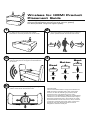
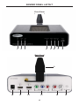
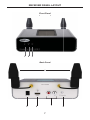
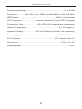
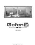
Wireless For
UWB
EXT-WHDMI
User Manual
www.gefen.com
f
ASKING FOR ASSISTANCE
Technical Support:
Telephone
Fax
(818) 772-9100
(800) 545-6900
(818) 772-9120
Technical Support Hours:
8:00 AM to 5:00 PM Monday thru Friday.
Write To:
Gefen Inc.
c/o Customer Service
20600 Nordhoff St
Chatsworth, CA 91311
www.gefen.com
[email protected]
Notice
Gefen Inc. reserves the right to make changes in the hardware, packaging and
any accompanying documentation without prior written notice.
Wireless for HDMI UWB is a trademark of Gefen Inc.
© 2008 Gefen Inc., All Rights Reserved
All trademarks are the property of their respective companies
Rev X2
Wireless for HDMI Product
Placement Guide
Optimizing the placement of your Wireless for HDMI product can
increase performance and ensure that you are getting
the best possible range and signal quality.
1
3
It is important to consider the placement of the Wireless
for HDMI sender to achieve the best possible
performance. Receiver placement is not as crucial.
Placing the unit in a higher position (over 5 feet) will
ensure a clear path for the signal to be transmitted to
the receiver.
2
Placing the sender on a low shelf (under 3 feet) can
cause interruptions in the signal when an object or
person passes between the sender and receiver.
4
Best
Better
Good
Over 5 Feet
4-5 Feet
3 Feet
5
The signal can be fine tuned by slightly adjusting the
position of the sender and receiver units.
Important Note:
The recommended maximum range of the Wireless for
HDMI is 30 feet (10 meters) with a line of sight path.
However, as with all wireless type products, actual
performance may vary depending on the user’s
environment. The Wireless for HDMI may be affected by
interference from other wireless products and/or signal
attenuation (weakening) due to the proximity of certain
objects/materials such as walls, floors, doors, and other
construction materials that contain metal. Large home
appliances may also affect performance such as
refrigerators, washers and dryers.
CONTENTS
1
Introduction
2
Operation Notes
3
Features
4
Sender Panel Layout
5
Sender Panel Descriptions
7
Receiver Panel Layout
8
Receiver Panel Descriptions
9
Connecting The Wireless for HDMI UWB
10 Operating The Wireless for HDMI UWB
11 Specifications
12 Warranty
INTRODUCTION
Congratulations on your purchase of the Wireless for HDMI UWB. Your complete
satisfaction is very important to us.
Gefen
Gefen delivers innovative, progressive computer and electronics add-on solutions
that harness integration, extension, distribution and conversion technologies. Gefen’s
reliable, plug-and-play products supplement cross-platform computer systems,
professional audio/video environments and HDTV systems of all sizes with hardworking solutions that are easy to implement and simple to operate.
The Gefen Wireless for HDMI UWB
The Gefen Wireless for HDMI UWB is the perfect solution for sending up to three
High Definition Video sources to any one location without the hassle of wires. Up to
30 feet ,line of sight (less if going through a wall to an adjacent room), is achievable
with supported resolutions of up to 1080p/30. This is a perfect solution in scenarios
where traditional cabling cannot be applied. The plug and play installation makes
it simpler than ever to extend HDMI to another room or to a ceiling projector in a
matter of minutes, all without ever having to get on a ladder or drill through walls and
ceilings. The Gefen Wireless for HDMI UWB uses Ultra Wide Band technology from
T-Zero which operates in the 3.1-4.8Ghz band. UWB will not interfere with your other
concurrently running wi-fi wireless products.
The Gefen Wireless for HDMI doubles as a High Definition video switcher. There are
three High Definition video inputs (2 HDMI and 1 Component) that are selectable at
the sending location. Three high definition sources, one wireless solution.
If the wireless receiver is located in an adjacent room, the IR repeater feature will
relay remote control commands from your location back to the source. Once the
IR blaster has been properly placed on the source device(s), you simply point your
existing remote control at the receiver which will send the remote commands back to
your device(s) for a truly seamless high definition experience.
How It Works
The Gefen Wireless for HDMI UWB uses a simple send and receive methodology.
There is one sending unit that is paired to one receiving unit at a remote location. All
communication sent between these units are done using wireless signals. Connect
up to 2 HDMI and 1 Component video source to the transmitting unit and connect the
display, with optional analog audio, to the receiving unit. Once the included power
supplies are connected and the display and sources are turned on, you will be able
to enjoy High Definition quality video at your display location.
To switch between the available inputs, press the input selector switch located on
the sender’s front panel. Alternatively, you can use the Auto Switching feature that
will monitor both HDMI ports and switch to inputs when it detects that either HDMI
source’s power has been turned on. When that HDMI device is tuned off, the Gefen
Wireless for HDMI UWB will automatically switch back to last viewed source. To
switch to the component input, simply turn off both of the connected HDMI sources or
use the input selector switch on the sender unit.
1
OPERATION NOTES
READ THESE NOTES BEFORE INSTALLING OR
OPERATING THE WIRELESS FOR HDMI UWB
•
This equipment may only be operated indoors. Operation outdoors is in
violation of 47 U.S.C.301 and could subject the operator to serious legal
penalties. Operation is subject to the following two conditions:
1.
This device may not cause harmful interference.
2.
This device must accept any interference received including interference
that may cause undesired operation.
•
Wireless for HDMI UWB has a maximum range of 30 feet when line of sight
is available. Distance may be limited or un-passable through certain types of
walls.
•
Operating temperature is 0° to 70° Celsius
•
HDMI 1.2a Compliant (HDMI 1.3 compatible)
•
HDCP Compliant
•
ROHS Compliant
•
Supported Resolutions
640 x 480
480i/p
576i/p
720p
1080i (60)
1080p (24, 25, and 30)
•
Supported Audio Formats:
HDMI Audio
-
2 Channel PCM (32KHz, 44.1KHz, and 48KHz)
Compressed 2 Channel and Multi-Channel bit-stream (e.g. Dolby Digital
& DTS)
Analog Audio
•
2 Channel LPCM (32KHz, 44.1KHz, and 48KHz)
Supported IR Formats (36KHz to 40KHz Only):
RC-5
RC-6
REC-80
2
FEATURES
Features
•
Real-time, visually lossless HD video compression
•
Two HDMI inputs and one Component Video / Analog Audio input
•
Fully HDMI and HDCP compliant
•
Supports HDMI 1.3 Lip Sync features for source devices
•
IR Blaster and IR Receiver jacks
•
Input Selector Switch
•
2-ch Audio and PCM @ 32KHz, 44.1KHz, 48KHz supported as well as
multichannel compressed 5.1 audio
Package Includes
(1) Wireless for HDMI UWB Sender Unit
(1) Wireless for HDMI UWB Receiver Unit
(2) 5V DC / 2.5A Power Supplies
(1) User’s Manual
3
SENDER PANEL LAYOUT
Front Panel
1
2
3
4
5
6
7
8
Back Panel
9
10
11
12
13
4
14
15
SENDER PANEL DESCRIPTIONS
1
Power LED Indicator
This LED will become active once the included 5V DC power adapter is properly
connected.
2
Video LED Indicator
This LED will be active while video is actively being transmitted between the
sending and receiving units.
3
Link LED Indicator
This LED will become active once a solid link has been established between the
sending and receiving units. If the distance between the units are too great and
a link can not be established, shorten the distance between the units until the
link indicator activates.
4
Component Video LED Indicator
This LED will become active when the component video input is selected and is
transmitting video.
5
HDMI 1 LED Indicator
This LED will become active when the HDMI 1 input is selected and is
transmitting video.
6
HDMI 2 LED Indicator
This LED will become active when the HDMI 2 input is selected and is
transmitting video.
7
Auto LED Indicator
This LED will become active when the Gefen HDMI For Wireless Extender
is using the Auto Selection feature. When this feature is active, the input will
automatically be selected when it detects that an HDMI source’s power has
been turned on.
8
Input Selector Button
Each press of the input selector button will cycle through the available video
inputs and the Auto Switching feature in the following order:
HDMI 1
9
HDMI 2
Component Video
Auto
Transmitting Antenna
This antenna must be in line of sight with the receiving antennas for best
possible performance. Do not disconnect or re-orient the position of this
antenna. Doing so may cause unexpected operation and may produce a
complete loss of signal.
5
SENDER PANEL DESCRIPTIONS (CONTINUED)
10 5V DC Power Input
Connect the included 5V DC power supply to this input and the power outlet.
11 HDMI 1 Input
Connect a HDMI/DVI source to this input.
12 HDMI 2 Input
Connect a HDMI/DVI source to this input.
13 Component Video Input
Connect a component video source to this input.
14 Stereo Analog Audio Input
Connect the stereo analog audio source that will be used when the component
source is selected. The audio from this port will also be used when a DVI display
is detected by the receiving unit.
15 IR Emitter/Blaster Port
An optional IR emitter/blaster connects to this port to relay IR commands that
are captured by the IR receiver on the Gefen Wireless for HDMI UWB receiving
device. The IR emitter head connects to the IR receiver of a source device.
6
RECEIVER PANEL LAYOUT
Front Panel
1
2
3
Back Panel
4
5
7
6
7
8
RECEIVER PANEL DESCRIPTIONS
1
Power LED Indicator
This LED will become active once the included 5V DC power adapter is properly
connected.
2
Video LED Indicator
This LED will be active while video is actively being transmitted between the
sending and receiving units.
3
Link LED Indicator
This LED will become active once a solid link has been established between the
sending and receiving units. If the distance between the units are too great and
a link can not be established, shorten the distance between the units until the
link indicator activates.
4
Receiving Antennas
These antennas must be in line of sight with the transmitting antenna for best
possible performance. Do not disconnect or re-orient the position of these
antennas. Doing so may cause unexpected operation and may produce a
complete loss of signal.
5
5V DC Power Input
Connect the included 5V DC power supply to this input and the power outlet.
6
HDMI Output
Connect the viewing display to this output port. If the detected display is a DVI
type, the analog audio inputs on the Gefen Wireless for HDMI UWB will be
used for the audio input. The analog audio output ports will also be active on the
receiving unit.
7
Stereo Analog Audio Output
The stereo analog audio output ports will always be active when the audio
source is 2 channel audio. When multi-channel audio is used, these outputs will
be disabled. This output will be active when a DVI type display is detected on
the HDMI output port and will use audio from the analog stereo input jacks on
the sender.
8
IR Receiver Extension Port
An optional IR receiver extension is connected to this port for use with the IR
repeater feature. IR commands that are received through the IR receiver will be
transmitted back to the source for output through attached IR blaster.
8
CONNECTING THE WIRELESS FOR HDMI UWB
How to Connect the Wireless for HDMI UWB
1.
Connect the source devices to the Wireless for HDMI UWB sender inputs.
Available inputs are as follows:
HDMI 1
Connect a HDMI/DVI (with a DVI to HDMI adapter) source
device to the HDMI 1 input port using a user supplied HDMI
cable.
HDMI 2
Connect a second HDMI/DVI (with a DVI to HDMI adapter)
source device to the HDMI 2 input port using a user supplied
HDMI cable.
Component Connect a component source device to the component input
port using the supplied 5 RCA component/audio cable (Red,
Green, and Blue).
2.
Connect the analog audio for the component source, or if you are using a
DVI source, to the analog audio input ports on the Wireless for HDMI UWB
transmitting device using a user supplied 5 RCA component/audio cable
(Red and White).
3.
Connect the HDMI display to the Gefen Wireless for HDMI UWB receiving
device HDMI output port using a user supplied HDMI cable. If using a DVI
display use either a HDMI to DVI adapter or cable.
4.
Connect the stereo analog audio output to the stereo analog audio inputs on
either an external audio receiver or the display using a user supplied 2 RCA
stereo analog audio cable.
5.
If using the IR repeater feature, connect the optional IR blaster between
the Gefen Wireless for HDMI UWB sender device and the source device’s
IR receiver. Connect the optional IR receiver extension to the Wireless for
HDMI receiver. Place the IR receiver head in a location where it will be in line
of sight with your IR remote control device(s).
6.
Connect the included 5V DC power supplies to the Gefen Wireless for HDMI
UWB sending and receiving devices.
7.
Power on the display first and the source devices second.
NOTE: The Wireless for HDMI UWB will detect and link the sending and
receiving units together and will require no further configuration to begin video
and audio transmission.
9
OPERATING THE WIRELESS FOR HDMI UWB
Auto Switching Feature
The Auto Switching feature on the Wireless for HDMI will monitor both of the
HDMI input ports and will automatically switch when it detects that an a HDMI
source’s power has been turned on. The memory feature will automatically return
to the last viewed source when the unit detects that an HDMI source has been
turned off. To access the component source, simply turn off the power to both
of the HDMI sources and the component source will automatically be selected.
To activate this feature, press the Input Selector button on the front panel of
the sender unit until the AUTO LED becomes active. To deactivate this feature,
simply use the Input Selector button to cycle to the next input.
Manual Switching
Manual switching can be accomplished by pressing the Input Selector button
located on the front panel of the Wireless for HDMI UWB sending unit. Each
press of this button will cycle through the available inputs. The cycling function
operates in the order below:
HDMI 1
HDMI 2
Component Video
10
Auto
SPECIFICATIONS
Frequency band range ...................................................................... 3.1 - 4.8 GHz
Resolutions ............. 480i, 480p, 720p, 1080i and 1080p@24Hz, 25Hz, and 30Hz
HDMI Version ..................................................................... HDMI v1.2a Compliant
CEC Compliancy ......................... Consumer Electronics Control (CEC) compliant
Compression Type ........................... ADI JPEG 2000 visual lossless compression
Operating temperature .............................................................. 0 to 70 degrees C
Operating humidity ....................... 10% to 90% relative humidity, non-condensing
Power Supply / Consumption ................................................ 5V DC / 12.5W max.
FCC Compliant ................................................................. FCC Compliant Part 15
Dimensions ................................................................................... 6”W x 2”H x 4”D
Shipping Weight ............................................................................................ 6 lbs.
11