1
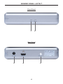
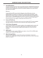
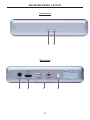
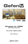
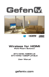
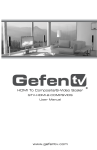
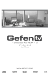
Wireless for
Extender
GTV-WHDMI
User Manual
www.gefentv.com
ASKING FOR ASSISTANCE
Technical Support:
Telephone
Fax
(818) 772-9100
(800) 545-6900
(818) 772-9120
Technical Support Hours:
8:00 AM to 5:00 PM Monday through Friday, Pacific Standard Time.
Write To:
Gefen Inc.
c/o Customer Service
20600 Nordhoff St
Chatsworth, CA 91311
www.gefen.com
[email protected]
Notice
Gefen Inc. reserves the right to make changes in the hardware, packaging and
any accompanying documentation without prior written notice.
Wireless for HDMI is a trademark of Gefen Inc.
© 2009 Gefen Inc., All Rights Reserved
All trademarks are the property of their respective companies
Rev A
CONTENTS
1
Introduction
2
Operation Notes
3
Features
4
Sender Panel Layout
5
Sender Panel Descriptions
6
Receiver Panel Layout
7
Receiver Panel Descriptions
8
Connecting And Operating The Wireless For HDMI
9
Specifications
10 Warranty
INTRODUCTION
Congratulations on your purchase of the Wireless for HDMI. Your complete
satisfaction is very important to us.
Gefen TV
Gefen TV is a unique product line catering to the growing needs for innovative
home theater solutions. We specialize in total integration for your home theater,
while also focusing on going above and beyond customer expectations to ensure
you get the most from your hardware. We invite you to explore our distinct
product line and hope you find your solutions. Don’t see what you are looking for
here? Please call us so we can better assist you with your particular needs.
The Gefen TV Wireless for HDMI
The GefenTV Wireless for HDMI Extender delivers a plug and play wireless
solution for HDMI sources placed up to 100 feet (30 meters) away. Hi-def
resolutions of up to 1080p/30 or 1080i/60 are supported with 5.1 digital audio and
additional L/R analog audio inputs. Broadcast mode allows extension of HDMI to
up to 5 wireless locations (without HDCP), while Unicast mode extends HDMI to
a single wireless location (with HDCP).
The GefenTV Wireless for HDMI Extender is a wireless solution for extending
any A/V sources utilizing HDMI such as satellite boxes, DVD players , and BluRay players to a remote display. The Wireless for HDMI will even penetrate
through walls and does not require line-of-sight alignment of the units.
How It Works
The GefenTV Wireless for HDMI Extender uses one sender and one or more
receiver units. A short cable connects the HDMI input of the sender unit to the
HDMI output of an HDMI source. At the display side, a short cable connects the
HDMI output of the receiver unit(s) to the HDMI input of the HDTV display(s).
The HDMI signal from the HDMI source travels to the HDMI display(s) over 5
GHz radio waves, and a vibrant and crisp High Definition picture emerges on the
HDTV display(s).
Note: Multichannel Audio: Compressed audio as well as analog audio are
formats supported depending on the capability of the input device. Please refer to
the Specifications section for further details.
1
OPERATION NOTES
READ THESE NOTES BEFORE INSTALLING OR
OPERATING THE WIRELESS FOR HDMI
•
This equipment may only be operated indoors. Operation outdoors is in
violation of 47 U.S.C.301 and could subject the operator to serious legal
penalties. Operation is subject to the following two conditions:
1.
This device may not cause harmful interference.
2.
This device must accept any interference received including interference
that may cause undesired operation.
•
Multiple sets in close proximity may cause interference with each other. This
rule does not apply when using the Broadcast Mode as multiple receiver
units are used to connect to one sender unit. All receiving units in this
scenario will be on the same channel.
•
HDMI 1.2 compliant
•
Maximum extension distance is 100 feet with a clear line-of-sight.
Obstructions such as walls and furniture may reduce performance and
distance ratings.
•
Maximum supported resolution is 1080p at 30Hz
•
Gefen recommends placing both units into the provided stands to help
produce the strongest possible transmission signal.
•
When using the units in Broadcast Mode HDCP encrypted material cannot
be used.
•
A maximum of 5 receiver units can be connected to one sender unit while
using Broadcast Mode.
•
When using the units in Unicast Mode HDCP encrypted material can be
used with an HDCP compliant display.
•
Supported Resolutions: 640x480, 800x600, 1024x768, 480i, 480p, 576i,
576p, 720p, 1080i and 1080p@30Hz
2
FEATURES
Features
•
Fully HDMI 1.2 compliant
•
HDCP compliant
•
Real-time un-compressed audio/video
•
Multichannel compressed 5.1 audio support
•
PCM Supported when using HDMI @ 32, 44.1 and 48 KHz
•
Dolby Digital™ 5.1 Surround Sound output on HDMI supported with number
of channels dependent on how many channels the sink device supports
•
Receiver Connectors: HDMI output, Analog Audio outputs (1 pair Left and
Right RCA jacks)
•
Sender Connectors: HDMI input
Package Includes
(1) Wireless for HDMI Sender unit
(1) Wireless for HDMI Receiver unit
(1) Two Universal 5V DC 2.6A Power Supplies
(1) 6-Foot HDMI Cable (M-M)
(1) User’s Manual
3
SENDER PANEL LAYOUT
Front Panel
1
2
Back Panel
3
4
5
4
SENDER PANEL DESCRIPTIONS
1
Link LED Indicator
This LED will become active once a solid link has been established between the
sending and receiving units. If the distance between the units are too great and
a link can not be established, shorten the distance between the units until the
link indicator activates.
Behavior:
A quick blinking LED means that the Sender unit and Receiver unit are
establishing a connection (including HDCP authentication) wirelessly. A slow
blinking LED means that the connection has been established and the audio /
video is about to be passed over from Sender to Receiver. A steady LED means
that the whole set of GTV-WHDMI units are on proper operation and there is
picture showing on the display connected to the Receiver unit.
2
Power LED Indicator
This LED indicator will become active once the included 5V DC power adapter
has been properly connected to the unit and an open wall power socket.
3
5V DC Power Receptacle
Connect the included 5V DC power supply to this receptacle and an open wall
power socket. Only use the power supply that is provided with this product.
Usage of non-authorized power supply may damage the unit and void the
warranty.
4
HDMI Input
This input will accept a single HDMI source device. Use a DVI to HDMI cable/
adapter when using a DVI input device.
5
Mode Change Button
This button will toggle the mode of the sender unit between Unicast and
Multicast. For a description of these modes and instructions on how to set them
please see page 8.
5
RECEIVER PANEL LAYOUT
Front Panel
1
2
Back Panel
3
4
5
6
6
RECEIVER PANEL DESCRIPTIONS
1
Link LED Indicator
This LED will become active once a solid link has been established between the
sending and receiving units. If the distance between the units are too great and
a link can not be established, shorten the distance between the units until the
link indicator activates.
Behavior:
A quick blinking LED means that the Sender unit and Receiver unit are
establishing a connection (including HDCP authentication) wirelessly. A slow
blinking LED means that the connection has been established and the audio /
video is about to be passed over from Sender to Receiver. A steady LED means
that the whole set of GTV-WHDMI units are on proper operation and there is
picture showing on the display connected to the Receiver unit.
2
Power LED Indicator
This LED indicator will become active once the included 5V DC power adapter
has been properly connected to the unit and an open wall power socket.
3
5V DC Power Receptacle
Connect the included 5V DC power supply to this receptacle and an open wall
power socket. Only use the power supply that is provided with this product.
Usage of non-authorized power supply may damage the unit and void the
warranty.
4
HDMI Output
This output will accept a single HDMI capable output device. Use a HDMI to DVI
cable/adapter when using a DVI capable output device.
5
Analog Stereo Audio RCA Outputs
Connect an amplified stereo output device, such as a stereo receiver, for
external amplification of audio transmitted from the sender unit. These outputs
will only be active when the audio carried along the HDMI source is 2 channel
LPCM.
6
Mode Change Button
This button will toggle the mode of the receiver unit between Unicast and
Multicast. For a description of these modes and instructions on how to set them
please see page 8.
7
CONNECTING AND OPERATING THE WIRELESS FOR HDMI
How to Connect the Wireless for HDMI
1.
Connect the source device to the Wireless for HDMI sender input using the
supplied HDMI cable. Use a DVI to HDMI cable/adapter when using a DVI
source device.
2.
Connect the HDMI display to the Wireless for HDMI receiving device’s HDMI
output port using a user supplied HDMI cable. Use a HDMI to DVI cable/
adapter when using a DVI capable display.
3.
Connect the stereo analog audio output on the Wireless for HDMI receiver
unit to the stereo analog audio inputs on either an external audio receiver or
the display using a user supplied 2 RCA stereo analog audio cable.
NOTE: This output will only be active when the audio carried along the HDMI
source is 2 channel LPCM.
4.
Connect the included 5V DC power supplies to the Wireless for HDMI
sending and receiving units.
5.
Power on the display first and the source devices second.
NOTE: The Wireless for HDMI will detect and link the sending and receiving
units together and will require no further configuration to begin video and audio
transmission.
Unicast and Broadcast Modes
Unicast Mode will only allow one receiver unit to be connected to one sender
unit at any given time. By default, the units will be configured for Unicast. In
Unicast Mode the power LED on both units will be GREEN. Both units must be
in the same mode for proper operation. Modes cannot be mixed.
Broadcast Mode will allow multiple receiver units (up to 5) to be connected
to one sender unit. In this mode, HDCP encrypted material is not usable. In
Broadcast Mode the power LED will be RED. To change modes--Unicast to
Broadcast or Broadcast to Unicast--please use the directions below.
1.
With both sender and receiver units powered on, press and hold the Mode
button on the sender unit for approximately 10 seconds.
2.
Release the Mode button. The front panel LED lights should turn off and
re-initialize in the new mode. The power LED will change colors depending
on what mode the unit has been switched to. If, after releasing the button,
the LED does not turn off, repeat steps one and two while holding the Mode
button down for a longer period of time.
3.
Repeat the above steps, but with the receiver unit(s).
4.
The units will re-establish a link and video transmission will begin.
8
USING THE VERTICAL STAND
A vertical stand is included for
placing the each main unit in an
upright position. Vertical orientation is
preferred because of the way that the
radio waves are transmitted/received.
Remove the main units and the
stands from the packaging.
1
To place a main unit into a stand, first
orient the front of the stand (where
the logo is located) with the LED’s on
the front panel of the main unit. Lower
the unit into the stand. There are
channels
located on both the main
unit and stand that will help guide the
main unit into the stand.
2
3
Apply firm pressure until the units
snap together. Both the front and rear
sections of the main unit must click
into the stand . To remove the main
unit from the stand, simply pull the
main unit and stand apart.
WARNING: Placing the main units
into the stand in the improper direction
may result in damage to the main unit
and/or stand.
9
SPECIFICATIONS
Frequency band range ...................................................................... 5.1 - 5.8 GHz
HDMI Compliancy ......................................................................................... v1.2a
Supported Resolutions: 640x480, 800x600, 1024x768, 480i, 480p, 576i, 576p,
720p, 1080i and 1080p@30Hz
Distance Rating ..................................................................... 100 feet line-of-sight
Operating temperature .............................................................. 0 to 50 degrees C
Operating humidity ....................... 10% to 90% relative humidity, non-condensing
Power Supply / Consumption .................................................. 5V DC / 13W (max)
Dimensions (Sender & Receiver) .................................... 6.5” W x 1.5” H x 6.5” D
Dimensions (Plastic Bases, Each) ............................ 3.4” W x 0.8-1.1” H x 8.5” D
FCC Compliancy ........................................................................................ Part 15
Shipping Weight .......................................................................................... 10 lbs.
10