1
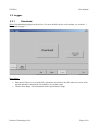
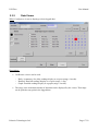
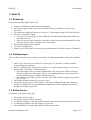
USI Flow
User Manual
USI Flow
USER MANUAL
Version – 1.0
Pulsonic Technologies Ltd.
Riverside House
North Dean Business Park
Greetland
Halifax HX4 8LR
U.K
Tel.: +44(0) 1422 363 462
Fax: +44(0) 1422 363 275
Pulsonic Technologies Ltd.
Page 1/22
USI Flow
User Manual
Table of Contents
1 Revision History..............................................................................................................................3
2 Design..............................................................................................................................................4
2.1 Run......................................................................................................................................4
2.1.1 Text.........................................................................................................................4
2.1.2 Graph......................................................................................................................5
2.1.3 Echo Profile............................................................................................................6
2.1.4 Display Config........................................................................................................7
2.2 Setup....................................................................................................................................8
2.2.1 System....................................................................................................................8
2.2.2 Device.....................................................................................................................9
2.2.3 Relay.....................................................................................................................10
2.2.4 IO..........................................................................................................................11
2.2.5 Calibrate Input......................................................................................................12
2.2.6 Site Details............................................................................................................14
2.2.7 About....................................................................................................................15
2.3 Logger...............................................................................................................................16
2.3.1 Download..............................................................................................................16
2.3.2 Data Viewer..........................................................................................................17
3 How To..........................................................................................................................................18
3.1 Download..........................................................................................................................18
3.2 Calibrate Input...................................................................................................................18
3.3 Define Device...................................................................................................................18
4 Wiring Diagram.............................................................................................................................20
5 Dimension......................................................................................................................................21
6 Glossary of Terms..........................................................................................................................22
Pulsonic Technologies Ltd.
Page 2/22
USI Flow
User Manual
1 Revision History
Version
Date
Modifications
Approved by PTL
V1.0
21/09/2012
Original
V CHAPRONT
V2.0
18/03/2013
Change UI, added
dimensional diagram
V CHAPRONT
Welcome to the USI. The USI uses intuitive programming through its touch screen display.
The user will navigate through the different screen with ease to calibrate, programme and
display chosen options. This largely negates the need for a detailed instruction manual and
provided the user is familiar with the generic terms (see glossary) he or she should enjoy
trouble-free operation.
Pulsonic Technologies Ltd.
Page 3/22
USI Flow
User Manual
2 Design
2.1 Run
2.1.1
Text
What: Display the current readings value.
Description:
•
•
Displays the value of Flow, Temperature, Totaliser, and all of the defined inputs.
The box below the value displays the daily readings of the last 7 days. Scroll to view.
Pulsonic Technologies Ltd.
Page 4/22
USI Flow
2.1.2
User Manual
Graph
What: Shows the measured readings as a graph.
Description:
•
•
Show each readings as a graph.
The range of the graph is defined in Setup-System (see section 2.2.1 System on page 8).
Pulsonic Technologies Ltd.
Page 5/22
USI Flow
2.1.3
User Manual
Echo Profile
What: Show the actual signal received by the sensor.
Description:
•
•
The signal received by the sensor is display on the graph.
The distance calculated is shown by a green arrow at the top of the graph.
Pulsonic Technologies Ltd.
Page 6/22
USI Flow
2.1.4
User Manual
Display Config
What: Shows the current configuration of the device
Pulsonic Technologies Ltd.
Page 7/22
USI Flow
User Manual
2.2 Setup
2.2.1
System
What: Configure the USI.
Description:
•
•
•
•
Units: Set the units used to display value. If the system of units (Metric or Imperial) is
changed, the USI will have to be reset to its factory settings. Please download any data
before doing that (see section 3.1 Download on page 17);
Log Interval: Define the time between each logged value. The USI will read value every
seconds on that interval and logged the average at the end of the interval;
Communication: Enable and configure the Ethernet capabilities. The IP address and the
password will be required to connect to the USI.
User Password: Factory default is 0001
Pulsonic Technologies Ltd.
Page 8/22
USI Flow
2.2.2
User Manual
Device
What: Define the primary device used to measure the flow.
Description:
•
•
•
Device: Describe the type the dimensions of the device used to measure the flow (for more
details, see see section 3.3 Define Device on page 17)
Temperature: If “Manual temp.” is checked, the USI will use a user defined temperature to
calculate the distance, otherwise the temperature read by the sensor will be used.
Span: The USI calculates the maximum flow span for the dimensions programmed.
Calibration
To calibrate the flow meter with the primary device you must enter the distance from the sensor
to the zero flow point of the primary device. This is the bottom of the notch on V-notch weir and
a rectangular flume and the bottom of the channel in a flume.
Do not use a measure to make this measurement
Ensure no flow is flowing through the primary device and put the USI into run mode. Record
the distance that is displayed on the USI screen. This is an accurate measurement of the zero
calibration point.
Enter this value as the “No Flow Distance”.
Pulsonic Technologies Ltd.
Page 9/22
USI Flow
2.2.3
User Manual
Relay
What: Configuration screen for the relays.
Description:
•
Up to 6 relays can be configured at the same time.
•
Relays can be configured as:
◦ Flow switch: start when the flow goes below (or above) the defined ON, and stop when
the flow goes above (or below) the defined OFF point;
◦ Sampler: start for 1 second every time the flow meter record the defined volume (ON
point)
◦ Penstock Up and Penstock Down: Control a penstock gate
◦ Parameters: Conductivity, Temperature, Turbidity, DO, pH.
Pulsonic Technologies Ltd.
Page 10/22
USI Flow
2.2.4
User Manual
IO
What: Define optional input and output.
Description:
•
•
•
Can read up to 3 4-20mA input channel, 1 internal pH, and can write to up to 4 4-20mA
output channel.
When an input is defined, it has to be calibrated (see section 2.2.5 Calibrate Input on page
12).
The USI has a dedicated pH input channel to which a pH probe can be connected.
Pulsonic Technologies Ltd.
Page 11/22
USI Flow
2.2.5
User Manual
Calibrate Input
What: Calibrate the input
Description:
Pulsonic Technologies Ltd.
Page 12/22
USI Flow
•
User Manual
Calibrate the input readings by settings two points (for more details, see section 3.2
Calibrate Input on page 17).
Pulsonic Technologies Ltd.
Page 13/22
USI Flow
2.2.6
User Manual
Site Details
What: Details of the site in which the device is installed.
Description:
•
The Name and the ID are used to name the data file. Please enter something meaningful to
help recognise the file.
Pulsonic Technologies Ltd.
Page 14/22
USI Flow
2.2.7
User Manual
About
What: Display version and copyright information.
Description:
•
Version: The version of the software.
Pulsonic Technologies Ltd.
Page 15/22
USI Flow
User Manual
2.3 Logger
2.3.1
Download
What: Download data logged on the device. For more details on how to download, see section 3.1
Download on page 17.
Description:
•
•
Download: If there is an existing file, append the new data to the file, otherwise create a file
and ask whether to download everything or just a time range;
Choose Date Range: Download data in the specified time range.
Pulsonic Technologies Ltd.
Page 16/22
USI Flow
2.3.2
User Manual
Data Viewer
What: Configure a viewer to display previous logged data.
Description:
•
3 difference viewer can be used:
◦ Daily: A summary of a daily readings display as a report (range: 4 weeks).
◦ Detailed: Detailed readings display as a report (range: 1 day).
◦ Graph: Detailed readings display as a graph (range: 4 weeks).
•
The range is the maximum amount of data that can be displayed by the viewer. That range
can be picked at any point in the logged data.
Pulsonic Technologies Ltd.
Page 17/22
USI Flow
User Manual
3 How To
3.1 Download
To download the data logged by the USI:
1. Connect a USB stick to one of the front USB port;
2. Go into the Logger menu. If you were in the Run menu, you will have to enter your
password;
3. Go into the Download sub-menu (see section 2.3.1 Download on page 15 for the interface)
4. Press the “Download” button
• If you have an existing file on your USB stick, the USI will automatically transfer any
new data to the file;
• If you do not have an existing file, you will be asked if you want to download all of the
data stored on the USI, or just the one in a time range.
5. Wait until the download is complete;
6. Go back to the Run menu;
7. Remove your USB Stick (it is not necessary to disconnect as in other versions of Windows)
3.2 Calibrate Input
After you have selected a type of value to read from a 4-20mA input channel, you need to calibrate
it:
1. On the “IO” sub-menu (see section 2.2.4 IO on page 11), press the “Calibrate” button
corresponding to your Input.
2. On the “Calibrate Input” window (see section 2.2.5 Calibrate Input on page 12), for each
button under “New Value” do the following:
1. Press the button, next to it will be displayed the value read by the 4-20mA using the
previous calibration (if the input has never been calibrated before, the previous value
will be measured using a default calibration setting)
2. Once the Previous Value is stable, enter the value of the solution using the keypad and
press “Enter”.
3. Once both calibration points are set, press “Save”.
4. On the IO sub-menu, press “Read Value” to check the readings with the new calibration
setting. You might have to press the button multiple times as the readings are processed
through a moving average filter.
3.3 Define Device
To configure your device in the USI:
1.
2.
3.
4.
5.
Go into the “Setup” menu;
Go into the “Device Setup” sub-menu;
In “No Flow Distance” enter the distance between the sensor and the bottom of your device;
In “Max Flow Height” enter the height of your device;
The “Dead-band” is a space that will be invisible to the sensor.
Pulsonic Technologies Ltd.
Page 18/22
USI Flow
User Manual
6. In “Shapes” select the correct shape of your device. Each shape will require specific
dimension to calculate the flow correctly;
7. The “Span” is the maximum flow that can be measured by the device, and is updated in real
time when you change the dimension of your device
Pulsonic Technologies Ltd.
Page 19/22
USI Flow
User Manual
4 Wiring Diagram
Pulsonic Technologies Ltd.
Page 20/22
USI Flow
User Manual
5 Dimension
All dimensions are in millimetres.
Pulsonic Technologies Ltd.
Page 21/22
USI Flow
User Manual
6 Glossary of Terms
•
•
•
•
•
•
•
•
•
•
•
•
•
Angle – this is the angle of the V-notch.
Dead Band – this is a distance from the front face of the sensor which the instrument is blind to any
echoes. It has a minimum depending on the sensor model but can be extended to overcome false
echoes such as the lip of a flume.
Echo profile – the USI can display directly the echo received from the sensor.
Max Flow Height – The maximum height of liquid flow through the primary device that can be
measured. This gives the flow span.
No Flow Distance – The distance from the sensor to the surface when no flow is current
Penstock – a penstock is a mechanised gate that can be lowered into a flow channel to regulate flow
volumes.
pH external – a 4-20mA input signal from an external pH meter can be calibrated and logged by the
USI.
pH internal – the USI has an integrated pH meter which can be calibrated directly with a pH sensor.
Primary Device – Either a Flume or Weir through which the flow is to be measured
Rectangular Flume – most common flume found in Europe
Rectangular Weir – a square notch weir used for high flows
Totaliser – the totaliser is the cumulated volume that has flowed through the device from the start
of measurement.
USI – Universal Smart Instrument
Pulsonic Technologies Ltd.
Page 22/22