1
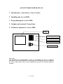
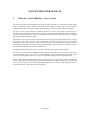
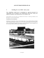
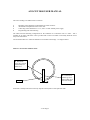
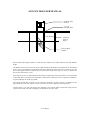
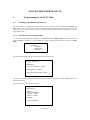
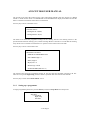
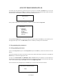
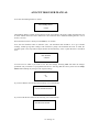
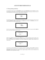
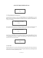
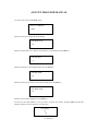
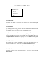
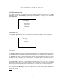
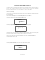
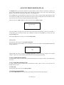
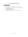
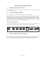
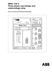
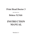
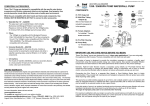
AVOCET-9000
Operation and Installation Manual
Sludge Blanket Monitoring System
Riverside House
North Dean Business Park
Stainland Road, Greetland
Halifax
W. Yorkshire, United Kingdom
Tel: 00 (44) 1422 363462
Fax: 00 (44) 1422 363275
E-mail: [email protected]
AVOCET 9000 USER MANUAL
1 Introduction - what it does –how it works
2 Installing the Avocet 9000
3 Programming the Avocet 9000
4 Outputs and external Connections
5 Telemetry options for Avocet 9000
Display
Output Relay Status LED
Clean Cycle LED
Fault LED
Program Buttons
Please note
The Manufacturers and Distributors accept no responsibility for losses or damages
incurred due to actions being taken or control processes occurring based on the outputs of
the Avocet 9000. When used in control applications protective precautions should be
installed.
V1-48 Page 2
AVOCET 9000 USER MANUAL
1
What the Avocet 9000 does – how it works
The Avocet 9000 monitors sedimentation of biological solids in tanks up to 7 metres (30 feet) deep. When
used in conjunction with its telemetry options then any number of remote tanks can be monitored
simultaneously from a control room situated within 500 metres (1,640 feet) of the tanks (site dependant).
The entry level for Avocet 9000 is an outstation attached to a sensor. This enables a single tank to be
monitored. The Avocet 9000 works by bouncing pulses of ultrasound off the sediment particles themselves.
The Avocet 9000 outstation can operate as a standalone instrument and provides alarm relays as standard
and optional 4-20mA and RS232 output.
The ultrasonic sensor probe is immersed just below the surface of the supernatant pointing directly towards
the bottom of the tank. The sensor both transmits the sonar pulse and then receives the returned
backscattered signal. The computer system in the Outstation processes this backscattered data to build up
the distribution of particles as a function of depth into the effluent. This is displayed in a graphical form on
the Outstation along with all relevant measurement data.
The graphical display allows the user to recognise the interface and the quality of the interface.
The Avocet 9000 only measures relative density as opposed to absolute. This is because during operation
the signal strength may vary due to factors such as turbidity of the supernatant and algal growth on the
sensor. The system adjusts for this over a range of magnitude by hunting for the strongest echo return.
During normal operation sludge blanket inversion and other processes can cause excessive fouling of the
sensor. If this happens then the purge cleaning facility should be used. A blast of either water or compressed
air is forced across the sensor face causing the obstructing matter to be removed. This autopurge increases
the time between any routine maintenance requirements.
V1-48 Page 3
AVOCET 9000 USER MANUAL
2
Installing the Avocet 9000 – basic system
Note: Installation should only be undertaken by approved personnel. No
responsibility can be accepted by the manufacturers from faults arising from
improper installation. The following notes are for guidance only.
Each Outstation in the system needs to be installed above the tank it is monitoring. Installation of the
Basestation is covered in a separate manual.
Installation of the Outstation
Outstations are normally fitted to static or circular sediment tanks. They may equally be fitted to rectangular
tanks with the traversing type of scrapers, but care must be taken to ensure that on such a tank, the sensor
(which is minimally immersed at water level) can never become fouled (typically by weirs or scum bars). If
there is any doubt about the suitability of the tank then consult the manufacturer. The usual installation is on
the circular type of tanks and this is the type of installation described.
V1-48 Page 4
AVOCET 9000 USER MANUAL
The issues needing to be addressed are as follows:
Mounting of the Outstation on the handrail or similar structure.
Attachment and adjustment of the Sensor arm.
Connecting of the Outstation to 115 V, 230 V or other suitable power supply.
Programming and commissioning.
1
2
3
4
The ideal and usual mounting configuration for the Outstation is to attach the unit to a frame – this is
available as an option, which also comes provided with a sensor arm which conveniently holds the sensor
away from obstructions.
Care should be taken as to where the Outstation is mounted on the bridge – see diagram below.
Plan View Of Circular Sediment Tank
A
Behind the
scraper may yield an
unrealistically low
blanket level.
B
Consideration
should be given to
sludge welling up in
front of the scraper
Bridge
Position B is usually better than A but may depend on the dynamics of the particular tank.
V1-48 Page 5
AVOCET 9000 USER MANUAL
Outstation main
enclosure
“U” bolt
mounting holes
Mounting
frame as
Option
Sensor Support
Channel
When mounted the display should be visible from the walkway and usually between waist and shoulder
height.
The tubular section of the sensor arm has a length matched to the height of the handrail above the effluent
surface. The open-ended elbow is attached to the frame with the M10 nylock bolt. The vernier screw in the
base of the support channel is adjusted to give an immersion depth of the grey PVC sensor of between 20
mm (0.78in) and 40 mm (1.57in).
There may be one or two cables attached to the sensor arm depending on the specification. If a second cable
is fitted then this is a pneumatic line (clear tube), which can be connected to an air compressor (available as
an option) through one of the grey glands.
The Coaxial signal cable connects into the instrument enclosure; the PVC sleeving is terminated at the
gland whilst the “SMC” RF connector screws on to the socket at the right hand side of the board.
Connect either 115 or 230 Volt supply to the Outstation. Care must be taken to adjust the voltage selector
switch located on the rear PCB accordingly. The default for the unit is 230V.
V1-48 Page 6
AVOCET 9000 USER MANUAL
3
3.1
Programming the AVOCET 9000
Selecting programmable parameters.
The Avocet device is programmed using the three keys on the front of the unit labelled UP, DOWN and
SET. If the Avocet is left for more than 50 seconds without a key being pressed the unit will revert to the
run mode. This is a safety feature to prevent an operator leaving the unit off line by forgetting to exit the
programming mode.
3.1.2 Viewing the current programme.
To view the current programme running press the SET key and select Display Setup from the options, then
press the SET key. If no key is pressed within a set time a timeout causes the unit to return to the Run
Mode.
Main Menu
Setup Menu
>>> Display Setup
Run Mode
The Avocet 9000 will display the current programme on four screens.
Software version: 1.48
HEAD SETUP
>Distance to tank bottom = 11.48(ft)
>Blanking distance = 2.30(ft)
> RELATIVE Threshold offset = 50(mV)
The first screen shows the basic head and tank settings used in the programme, and the sludge blanket level
detection threshold.
Press any key to move to the second screen.
RELAY SETUP:
>RELAY 1:
>Mode = HIGHLEVEL
>ON level = 6.56(ft)
>OFF level = 5.91(ft)
>RELAY 2:
>Mode = DISABLED
V1-48 Page 7
AVOCET 9000 USER MANUAL
The second screen shows the settings for the relays and indicates whether each relay triggers on a HIGH
LEVEL or LOW LEVEL alarm or is DISABLED. If not DISABLED the display shows the levels that the
alarm is switched on and the level the alarm is switched off.
Press any key to move to the third screen.
CLEANING SETUP:
>Cleaning interval = 60(mins)
>Cleaning duration = 15(secs)
The third screen shows the programme settings for the cleaning interval. The cleaning interval is the
operational time between cleaning cycles, and the cleaning duration is the time in seconds that the cleaning
relay will be active to enable an external device to perform a clean of the sensor in the tank.
Press any key to move to the fourth screen.
PROCESSING SETTINGS:
> PRIMARY CLARIFIER DETECTOR
> Filter MEDIAN length = 5
> History length = 4
> Display scale = x1
> Detection type = PEAK
> SLOPE FILTERED (Filter Len = 4)
The fourth screen shows the programme settings for the echo detection algorithm selected by the user.
These are set up in the Engineering sub menu and are explained under that section of the manual.
Press any key to return to the MAIN MENU screen.
3.1.3 Setting up a programme.
To begin programming the device press the SET key and select Setup Menu from the options.
Main Menu
>>> Setup Menu
Display Setup
Run Mode
V1-48 Page 8
AVOCET 9000 USER MANUAL
You must now enter the device password in order to proceed. Use the UP and DOWN keys to enter the
password number and then press SET to continue. If you enter an incorrect password the system will return
automatically to the normal RUN MODE. The factory default password is 1.
Enter Password
>0
Once you have entered the correct password you will be presented with the Setup Menu.
SETUP MENU
>>> Setup Sensor
Setup Relays
Setup Cleaning
Set Time
Set Password
Engineering Menu
Run Mode
Using the UP and DOWN keys scroll to the option you require and press the SET key. This will take you to
the appropriate setup screen. The Run Mode option is reached by scrolling to the menu bottom
3.2 Programming the parameters.
3.2.1 Programming the sensor
Scroll to the Setup Sensor option of the Setup Menu and press the SET key. Follow the instructions on the
display.
First enter the distance in metres from the face of the sensor head to the bottom of the tank. Use the UP and
DOWN keys to indicate the appropriate value
In order to use SECONDARY CLARIFIER TANK or PEAK detection, the distance set for the bottom of
the tank must be about 0.2m less than the tank depth at its shallowest under the sensors detection field. This
value can be obtained using the Test ADC function in the Engineering menu.
Once the desired value is displayed press the SET key to enter the value shown and continue.
Enter head face to tank bottom distance
> 6.89(ft)
V1-48 Page 9
AVOCET 9000 USER MANUAL
Now enter the blanking distance in metres.
Enter Blanking Distance
> 2.30(ft)
The blanking distance extends out from the face of the sensor head to the point at which measurements can
be made without interference from obstructions. The instrument has a minimum blanking distance of 0.70
metres (2.30 feet).
When the desired value is shown press the SET key to continue.
Now enter the threshold value in millivolts (mV). The threshold value should be set to give reliable
readings, without giving false readings from interference pickup. The threshold will work on either the
returned signal or the slope-filtered signal. Below this threshold any value or peak detected is considered
noise.
Enter threshold
> 200(mV)
You will now be asked if you wish to save the new settings. Selecting YES will make the changes
permanent and you will have re-programmed the device. Selecting NO will return you back to the Setup
Menu without making any changes to the original settings.
Save Settings?
> No
Yes
If you select Yes the unit will show the following screen momentarily.
SAVING SENSOR SETTINGS
If you select No the unit will show the following screen momentarily.
SETTINGS NOT SAVED
V1-48 Page 10
AVOCET 9000 USER MANUAL
3.2.2 Programming the Relays
To program the relays scroll to the Setup Relays option of the Setup Menu and press the SET key. Follow
the instructions on the display. You will first be presented with a sub-menu showing the available relays that
can be programmed. Scroll to the relay required and press the SET key.
Relay Number?
>>> Relay 1
Relay 2
Exit
On selecting a relay you will be presented with another sub-menu scroll to the type of relay you are
configuring, HIGH or LOW level mode then press the SET key to continue. The DISABLE option can be
used to disable a previously programmed relay.
High/Low Alarm?
>>> HIGH
LOW
DISABLE
Once the relay mode has been selected you must then enter the relay ON level using the UP and DOWN
keys to set the value. Enter the value in metres.
Relay ON Level
> 6.56(ft)
Enter the relay OFF level using the UP and DOWN keys to set the value. Enter the value in metres. Note
that for a HIGH level relay the OFF value is always less than or equal to the ON value. This allows the
user to set a varying level of hysteresis for the relays enabling more complex control schemes to be
implemented.
Relay OFF Level
> 4.59(ft)
You will now be asked whether or not you wish to save the new settings. Selecting YES will make the
changes permanent and you will have re-programmed the relay. Selecting NO will return you back to the
Setup Menu without making any changes to the original settings. In both cases the instrument will
momentarily show an appropriate message.
V1-48 Page 11
AVOCET 9000 USER MANUAL
Save Settings?
> No
Yes
3.2.3 Programming the Cleaning Cycle
To program the head cleaning cycle scroll to the Setup Cleaning option in the Setup Menu and press the
SET key. Follow the instructions on the display. You will first be asked to enter the cleaning interval time.
This is the time interval in minutes between each cleaning cycle up to a maximum of 720 minutes. To
continue press the SET key.
Enter cleaning interval (1-720 mins)
>
10 (mins)
Next you will be asked to program the cleaning cycle duration in seconds. This is the amount of time that
the cleaning process will operate for up to a maximum of 600 seconds. To continue press the SET key.
Enter cleaning duration (1-600 secs)
>
8 (secs)
You will now be asked whether or not you wish to save the new settings. Selecting YES will make the
changes permanent and you will have re-programmed the cleaning cycle. Selecting NO will return you back
to the Setup Menu without making any changes to the original settings. . In both cases the instrument will
momentarily show an appropriate message.
Save Settings?
> No
Yes
3.2.4 Set Time
This option allows the user to set the internal real time clock. The present version of the Avocet has a
volatile clock function, i.e. when the unit is powered off the clock settings are lost. At the present time the
clock function is not used for logging data, so the user, without any detriment may omit setting the time
shown by the clock, from the programming procedure.
V1-48 Page 12
AVOCET 9000 USER MANUAL
To set the clock select the Set Time option.
Enter Year (2000-2099)
> 2009
Find the current year and then press the Set key.
Enter Month (01-12)
> 01
Find the current month (01 is January, to December is 12) and then press the SET key.
Enter date (01-31)
> 17
Find the current day of the month and then press the SET key.
Enter Hour (00-23)
> 09
Find the current hour in 24-hour clock format and then press the SET key.
Enter Minute (00-59)
> 30
23
Find the current minute and then press the SET key.
You will now be asked whether or not you wish to save the new settings. Selecting YES will make the
changes permanent and you will have re-set the Time.
Save Settings?
> No
Yes
V1-48 Page 13
AVOCET 9000 USER MANUAL
Selecting NO will return you back to the Setup Menu without making any changes to the original settings.
In both cases the instrument will momentarily show an appropriate message.
3.2.4 Setting a new password
To enter a new password scroll to the Set Password option in the Setup Menu and press the SET key. This
will take you to the set password screen. Enter the new password using the UP and DOWN keys and then
press the SET key when the new value has been selected.
ENTER NEW PASSWORD
> 1
You will now be asked whether or not you wish to save the new settings. Selecting YES will make the
changes permanent and you will have re-set the password. Selecting NO will return you back to the Setup
Menu without making any changes to the original settings. In both cases the instrument will momentarily
show an appropriate message.
Save Settings?
> No
Yes
3.2.5 Engineering Menu.
To enter the engineering menu scroll to the Engineering Menu option in the Setup Menu and press the
SET key.
This will bring up a new menu as shown below allowing the user to test the functionality of the unit and also
set up the detection algorithm to be used in the particular installation.
V1-48 Page 14
AVOCET 9000 USER MANUAL
ENGINEERING MENU
>>>Test Relays
Test ADC
Test 4-20mA
Show Password
Setup Processing
Comms Stream On/Off
Setup Measurement Units
Exit
3.2.5.1 Test Relays
Selecting this option will turn on each of the four relays with each key press. The associated LED on the
front panel will also be lit. This can be used to check the functionality of equipment controlled by the
relays.
3.2.5.2 Test ADC
The Test ADC option can be used to examine the echo returns from the settlement tank. On selecting this
option the display will show Sampling while the instrument collects a batch of echo returns from the tank.
The unit will then display a graph of the echo profile in mV versus distance in metres.
This option is useful for determining the current state of the tank and showing the distance to the tank
bottom, which is indicated by a large vertical echo return on the display. In a tank containing a very dense
sludge there may be no bottom echo at all due to the sludge totally absorbing the ultrasound pulse.
To exit the Test ADC routine press any key, then select the NO option from the Output to com? to return
to the Engineering Menu. If the YES option is selected the display shows ‘SENDING DATA’, while the
unit outputs an ascii formatted string to the serial port representing the current echo return as displayed on
the ADC trace.
3.2.5.3 Test 4-20mA
On selecting this option the unit will step up through the 4-20mA output settings starting at 0mA in 1mA
steps each time any key is pressed. After the 20mA step the Engineering Menu will be displayed.
This can be used to check the functionality of any equipment attached to the 4 to 20mA output as well as a
basic instrument check.
3.2.5.4 Show Password
Selecting this option will show the current password set by the user. Press any key to return to the
Engineering Menu.
V1-48 Page 15
AVOCET 9000 USER MANUAL
3.2.5.5 Setup Processing
This option allows the user to programme the detection algorithm and filtering settings. Scroll to the Setup
Processing option of the Engineering Menu and press the SET key. Selecting this will display the
Processing Menu.
Processing Menu
>>>Tank Type
Detection Type
Pre-processing
Display Scale
Output filter
Exit
3.2.5.5.1 Tank Type
Selecting Tank Type allows the user to select between two fundamentally different modes of operation.
Tank Type?
>>>Primary
Secondary
The two modes are designed for Primary clarifiers and Secondary clarifiers due to their differing Sludge
characteristics.
The Primary tank mode is designed for tanks with rapid settling dense sludge with good signal returns.
Selecting this mode of operation allows all the detection parameters to be manually set up as detailed below.
The Secondary tank mode is designed for secondary clarifiers where the sludge blanket has a low density
and diffuse interface, resulting in very low signal returns. This mode has all set-up parameters factory preset for optimum operation, except for the minimum peak height value setting.
Selecting Secondary tank brings up the minimum peak height setting. This is used to set a minimum
detection level, below which the instrument will ignore return signals. This is used to remove false blanket
detection caused by artefacts in the signal return from objects in the tank, such as pinfloc and algal bloom.
Initially set the minimum value to Zero and then adjust the value up to just above the signal returns
observed (given as the H=xxx figure in the lower right hand corner of the running display) when spurious
operation is observed.
NOTE setting this value too high will result in the sludge blanket level always reading zero.
V1-48 Page 16
AVOCET 9000 USER MANUAL
Enter min peak Height
> 1200
3.2.5.5.2 Detection Type
Selecting Processing Type from the options allows a choice of algorithms to detect the sludge layer when
in Primary tank type mode. The instrument supports three detection algorithms, peak detection, slope
detection or threshold crossing. The parameters for each of the algorithms are fully configurable by the user.
The basic details of each are outlined below.
Peak detection algorithm.
The peak detection algorithm searches for the highest return signal or signal slope above a user set threshold
level between the end of the blanking distance and the tank base. For this algorithm the head face to tank
bottom must be set to be less than the actual tank depth at the sensor, or the instrument will always detect
the bottom echo and disregard the desired sludge interface level.
Threshold crossing algorithm.
The threshold crossing algorithm searches for the first return signal to cross the user set threshold, starting
from the end of the blanking distance, moving towards the tank base. This method is insensitive to the echo
from the tank bottom being included in the analysis, so the tank bottom can be included in the sensor set-up.
Scroll to the Processing Type option of the Processing Menu and press the SET key.
This selection will present you with the detection algorithm selections.
Detection Settings?
>>> Peak
Threshold
Select the required echo detection algorithm required then press the Set key to display the Threshold type
selection menu.
Threshold
>>> Relative
Absolute
Select the required threshold type required then press the Set key.
The threshold menu allows the user to select the reference point used to calculate the baseline for the signal
detection threshold level.
V1-48 Page 17
AVOCET 9000 USER MANUAL
The relative option uses a dynamic baseline relative to the noise baseline present in the return signals. As
the noise varies with time the baseline will adjust to compensate for the varying noise levels. The absolute
option sets the threshold relative to a zero return signal (i.e. a noise free return signal).
3.2.5.5.3 Pre-processing
This menu allows you to adjust the actions performed on the raw echo signal prior to the application of the
processing algorithms.
Scroll to the Pre-processing option of the Processing Menu and press the SET key.
This selection will present you with the Pre-processing selections.
Pre-processing
>>> Signal History Length
Differential filter
Exit
Selecting the Signal History length option presents you with the following display.
Enter history length
>4
The History length value is the number of complete echo detection routines, which are then used to update
the level and 4 to 20mA outputs. Increasing the value will damp the system response.
Enter the history length required then press the SET key to return you to the Pre-processing menu.
The allowed length is from 1 to 32.
Selecting the Differential Filter option presents you with the following display.
Differential Filter
>>> Slope-Filtered
Unfiltered
V1-48 Page 18
AVOCET 9000 USER MANUAL
The slope-filtered setting multiplies the return signal with a differential filter, which outputs high peaks for
steep slopes. The algorithm then searches the output for either the highest peak, or the first slope, above a
user set threshold level, between the end of the blanking distance and the tank base.
If the slope filter is selected the length of the filter is then required.
Enter Slope filter length
>4
Scroll using the UP and DOWN keys to the appropriate length and press the SET key to return you to the
Pre-processing menu. The allowed values are 1 to 16.
3.2.5.5.4 Display Scale
The display scale is not strictly a processing method and only affects the size the returned signal is
displayed on the LCD screen for ease of viewing of small signals. This should be set up in both secondary
and primary tank modes.
Enter display scale
>1
Enter the display scale required then press the SET key to return you to the Processing menu.
The allowed scale is from 1 to 10. E.G. 2 will magnify the echo display with a factor of 2 times.
3.2.5.5.5 Output Filter
The output filter stores a number of the previous results and determines the final output from these values.
There are two types of filter available, Median and Average.
Filter Type?
>>> Median
Average.
Select the required filter type required then press the Set key.
V1-48 Page 19
AVOCET 9000 USER MANUAL
The Median filter type selects the output level as the median (or centre value of a sorted list) of a history of
stored values determined from the return signal. The filter will remove ‘shot’ noise of less than half the
duration of the filter but will delay the output by a corresponding time.
The Average filter type calculates the average level from a history of stored values determined from the
return signal. The length of the filter determines the amount a single reading affects the output but slows the
response time of the system by an amount determined by the length.
After the selection of Filter Type you will be asked to enter the Filter Length.
Enter filter length
>5
Select the number of sample sets to be used in the selected filter type from the previous step (median or
average filter type). The allowed values are 1 to 256 echo samples. Press the SET key to return you to the
Pre-processing menu.
Selecting the Exit option returns you to the Processing Menu.
3.2.5.5.6 Exit
Selecting this option will exit to the Engineering Menu.
First you will now be asked whether or not you wish to save the new settings. Selecting YES will make the
changes permanent.
Save Settings?
> No
Yes
Selecting NO will return you back to the Engineering Menu without making any changes to the original
settings. In both cases the instrument will momentarily show an appropriate message.
3.2.5.6 Comms Stream On/Off
Use this option to Enable or Disable the Test Data Streaming to the serial port (COM0). The default setting
is Disable.
3.2.5.7 Setup Measurement Units
Use this option to select the required unit of measurement. Select either (a) Metric or (b) Imperial. The
default setting is Metric.
3.2.5.8 Exit
Selecting this option will exit to the SETUP MENU.
3.2.6 Setting the Run Mode
Selecting the Run Mode option will exit the programming menu and start the unit running.
V1-48 Page 20
AVOCET 9000 USER MANUAL
Quick Setup Guide.
For rapid installation and evaluation, it is recommended that the following settings are used.
1
2
3
4
5
6
Set the tank depth set to 20cm (~ 8 inches) less than the actual tank depth.( Setup Sensor menu)
Set the Blanking distance to 0.70m (2.30 feet).
Set the threshold offset to 100mV.
Set the Tank type to a Secondary clarifier.
Set the minimum peak Height detection to zero.
Adjust the Display Scale to show the sludge level without filling the tank display screen
V1-48 Page 21
AVOCET 9000 USER MANUAL
4
Outputs and External Connections
All connections are made to the bottom of the main circuit board, which can be accessed by removing the
lower panel of the main unit.
4.1
4 to 20 mA Output (Optional)
This is available from 2 terminals in the lower compartment and is encoded as follows:
The 4-20 output is proportional to the percentage depth of the sludge blanket in the tank. Thus if the blanket
pointer (BP) was at the top of the display (zero depth) - this is not possible but will suffice for reasons of
explanation, then the percentage depth would be 100% and the output would be 20 mA. If there is no sludge
in the tank then the BP would be at the bottom of the display and the percentage depth would be 0% and the
output would be 4 mA. If as is more usual the BP was at 2 metres (6.56 feet) in a 4-metre (13.12 feet) tank
then the percentage depth would be 50% and the output would be 12 mA.
4.2
Relay Connections
The change-over relay contacts are accessible beneath the lower cover. The connections beneath this cover
are shown in the diagram below. All relay states are indicated by the LED’s on the front panel.
°
° ° °
N E L
SUPPLY
20mA
° ° °
° ° °
° ° °
° ° °
NO NC COM NO NC COM NO NC COM NO NC COM
RELAY1
RELAY2
CLEANING
FAULT
° ° ° ° °
° ° °
° °
Tx Rx RTS CTS GND Tx Rx GND - +
RS232-0
RS323-1 4SENSOR
5
Telemetry Options for the Avocet 9000
The basic standalone unit described in this manual can be linked along with any number of other standalone
units to a central control unit or Basestation using either the RS 232 connections or an additional “bolt-on”
radio module available as an option. For further details please contact Pulsonic Technologies Ltd.
V1-48 Page 22
AVOCET 9000 USER MANUAL
_______________Specifications_________________________
Tank Depth Range
0.7 m (~ 2.30 ft) to 7 m (~ 30 ft).
Level Resolution
This is a percentage of depth and is equivalent to 0.03 m (3cms) at 5 metres range.
Stability
0.1% /deg. Celsius.
Dead Zones
Normally 0 - 0.6 metres (0 ft - ~2 ft) and above 7 metres (~30 ft).
Temperature Range
-20 to +60 for the internal temperature in the enclosure.
Enclosure Protection
IP 65 for Outstation
Power Requirements
Either 110 Volts A.C. or 250 Volts A.C. Switch selectable.
Ultrasonic Sensor
The outstation is fitted with a low voltage tranceiver type operating at VHF.
Outputs
A single pole change over relay rated at 250 A.C. continuous
4-20 mA which encodes the blanket depth as a percentage of the tank depth.
2 trip point programmable relays.
Consult manufacturers if RS232 is required.
Features
The self-purging sensor reduces difficulties due to fouling.
The system is essentially non-invasive.
__________________________________________________________________________________
V1-48 Page 23