1
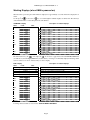
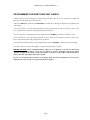
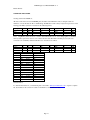
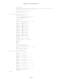
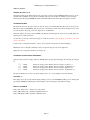
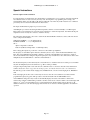
LMM Designs User Manual Multiflow – 2
LMM Designs
MULTI-FLOW
Serial No. Areo001
Model Example
Page 1
LMM Designs User Manual Multiflow – 2
Index
PAGE 3
INTRODUCTION TO THE MULTIFLOW.
PAGE 4
SPECIFICATIONS.
PAGE 5
FRONT PANEL TEST FUNCTIONS AND TEST.
PAGE 6
WORKING DISPLAYS
PAGE 7
PROGRAM THE IDENTS AND UNIT LABELS.
PAGE 8
PROGRAMMING THE MULTIFLOW.
PAGE 9
CARDS FITTED
PAGE 10
FREQUENCY INPUT CARD.
PAGE 11
PAGE 12
PAGE 13
TABLE CHANNEL 1 FREQUENCY DATA
TABLE CHANNEL 2 FREQUENCY DATA
TABLE CHANNEL 3 FREQUENCY DATA
PAGE 14
PT100 INPUT CARD
PAGE 15
PAGE 16
PAGE 17
CALCULATION OF OHMS TO TEMPERATURE
TABLE TEMPERATURE TO VISCOSITY
TABLE TEMPERATURE TO S.G.
PAGE 18
RS232 / RS485 COMMAND STRUCTURE.
PAGE 19
PAGE 20
CODE EXAMPLE
PORT SETTINGS
PAGE 21
SPECIAL OPTIONS.
PAGE 22
SETTING FOR OPTIONS
PAGE 23
PAGE 24
EQUATIONS AND DESCRIPTION
VISCOSITY FLOW DIAGRAM.
PAGE 25
TERMINAL DIAGRAM.
Page 2
LMM Designs User Manual Multiflow – 2
Introduction to the Linear Multi-Flow Meter (LMM) Mark 2.0
Designed to meet the ever changing requirements of flow metering, the Multiflow can be tailored to virtually any
flow application; from the most basic of rate and total indicators to a batcher or full control system, with computer
and printer interface. The system will operate with most peripherals i.e. Flow sensors, Pressure, Temperature Etc.
Each LMM is hand built to your own individual requirements, by selection from the options listed below. Special
software is written for each unit as and when required. Each function now has a stand alone card, up to 5 cards can be
added to your system.
Frequency Input Card Up to three frequency inputs can be accepted from flow sensors; each input with a 32
point linearisation curve for the derivation of flow and a programmable factor for unit conversion. Programmable cutoff points enable displays of both frequency and flow to be inhibited below pre-set values. The update is
programmable from 0.02 seconds up to virtual infinity.
Analogue Input Card 16 bit Resolution Up to six analogue process inputs 0-10V or 4 to 20mA, are
available for use with sensors of temperature; flow; density; viscosity; pressures - absolute, barometric, gauge or
differential, and other factors requiring compensation. Each input has a five point linearisation curve. For conversion
to alternative mass units a programmable mass factor can be used.
Analogue Output Card 16 bit Resolution Up to three analogue outputs 0-10V or 4 to 20mA, proportional
to any desired parameter, are available for connection to remote facilities such as alarms, indicators, chart recorders,
PLCs and the like. The analogue output reference parameter may be configured by the user.
Pulse Ouputs Three TTL or open collecter outputs are available for retransmission of rate, or for output of
pulses per unit volume of total. These outputs, too, may be connected to remote indicators, totalisers or PLCs.
Relay Card The Multi-flow can accommodate up to seven volt-free relays which can be deployed for alarm
purposes. If the process includes a batching unit or controller, the relays can be used to control valves solenoids or
pump starters
Communications To monitor parameters or programme calibration data RS232, RS485 and interfaces can be
incorporated. For connection to panel or desk mounted printers either a serial or parallel port can be incorporated,
with the option of time and date indication.
The Main Display The standard display is alphanumeric with red dot matrix characters, 152mm wide and
18mm high, which give an exceptionally wide viewing angle. The display itself comprises three fields: on the left, a
maximum of five characters may be used to give the parameter identity; in the centre is the read-out of the quantity
being measured; and to the right are the characters defining the units of measurement. These can be changed by the
end user. User test routines, and buzzer.
Data Entry All calibration data are entered by means of a hand-held infra-red keypad following a successful passcode entry.
To prevent incorrect data entry, when two Multiflow units are positioned in close proximity, the reception of the unit
that is not being addressed can be inhibited by a sequence of keystrokes on the front panel keyboard of that unit.
Page 3
LMM Designs User Manual Multiflow – 2
SPECIFICATION
Frequency: 32 point linearization curve of frequency versus flow rate; by interpolation between points and,
by extrapolation, from the first and last two points of the curve. An engineering factor is included for the conversion
of units.
Frequency range:
The default range is 0.5hertz to 65kHz with accuracy +/- 0.002Hz +/- least significant digit. A low cut off can be
programmed by the end user which will allow the LMM to measure frequency down to 0.01 of a Hz. The crystal
oscilator can be programmed to offset and errors by calibration.
Signal conditioning:
On request the LMM can take signals from contact closure (reed switch): sine wave; low level input to base of PNP
transistor and two wire modulated current frequency inputs. The default is a standard TTL type signal input or
voltage pulse.
Sensor Excitation Voltage:
An adjustable 5 to 24V dc output; 100mA each; available only when used on the mains ac supply. This can be set by
the end user See section Titled HardWare.
Analogue Inputs:
5 point linearisation, can be either 4 - 20mA or 0 - 10V dc.
Resolution: 16 bit
Accuracy: +/- 0.001% of full scale
Analogue Outputs:
Either 4 - 20mA or 0 - 10V dc.
Resolution: 16 bit
Accuracy: +/- 0.001% of full scale +/- least significant digit.
Pulse Outputs:
Relays:
TTL or Open Collector outputs with a range of 1 hertz to 1 kHz
Rating: 0.25A at 240Vac.
Power supply: A mains input or dc input can be used to supply the LMM. The 110/240Vac is selectable on
a switch inside the LMM see section entitled Hardware.
220 to 240Vac 50-60Hz will draw approx 18 mA
110 to 120Vac 50 -60Hz will draw approx 36 mA
12V dc will draw approx
24V dc will draw approx
mA
mA
(this depends on options fitted)
(this depends on options fitted)
(this depends on options fitted)
(this depends on options fitted)
Caution
Users are advised that although the equipment has protection and conforms to CE approvals, for trouble free operation the
Multiflow system should be connected to a clean power supply; ie free of noise and not in the same phase as heavy machinery.
Any machinery using heavy contacts in the immediate proximity of Multiflow should be suitably suppressed. Inductive loads
switched by the volt-free relay contacts should be fitted with suitable snubber networks.
Page 4
LMM Designs User Manual Multiflow – 2
FRONT PANEL TEST MODE
By pressing the at the same time the front panel set up and test mode are entered.
The display will show the following options by pressing the .
ENABLE IR
KEY CLICK
TEST REMOTE
MAN 1234
ALTER TO EXIT
Y
N
User ALTER to enable Y and disable N the IR keyboard
User ALTER to select Y and disable N the audible keyclick
Test the IR keyboard
Serial number of unit
Press ALTER to exit this mode
It should be noted that the exact order of each display will vary in the way that the cards are plugged in.
Page 5
LMM Designs User Manual Multiflow – 2
Working Displays (when LMM is powered on)
When the unit is powered up the serial number is displayed for approximately 5 seconds then the first display line is
shown.
Use the up ()key
or the down ()
key to scroll through the resultant displays see table below. The same keys
on the hand held remote control will perform the same function.
STANDARD Display
ident
result
1
rt
mas1
1
tv
1
tm
2
rt
2
mas
2
tv
tm 2
3
rt
3
mas
3
tv
3
tm
temp1
Visc
s.g
Description of resultant displays
units
n.nnn
n.nnn
n.nnn
n.nnn
n.nnn
n.nnn
n.nnn
n.nnn
n.nnn
n.nnn
n.nnn
n.nnn
n.n
n.nnn
n.nnn
Volume flow rate channel 1
Mass flow of turbine 1
Total volume of turbine 1
Total Mass of turbine 1
Volume flow of turbine 2
Mass flow of turbine 2
Total volume of turbine 2
Total Mass of turbine 2
Volume flow of turbine 3
Mass flow of turbine 3
Total volume of turbine 3
Total Mass of turbine 3
Temperature from Pt100
Viscosity of fluid
Specific Gravity of fluid
The left direction key ()
or the right ()
can be used to toggle between the STANDARD DISPLAYS
(see table above) and the RAW DISPLAYS (see table below). A message is momentarily displayed indicating which
section is selected. Use the direction keys to select a display.
RAW Display
ident
result
date
time
F
1
ROS
1
1
STO
KF
F
1
2
ROS
2
2
STO
KF
F
2
3
ROS
3
2
STO
KF
3
1
ohms
RELAYS
Description of resultant displays
units
dd/mm/yyyy
Hh:mm:ss
manifold
channel
volume
n.nnn
n.nnn
n.nnn
n.nnn
n.nnn
n.nnn
n.nnn
n.nnn
n.nnn
n.nnn
n.nnn
n.nnn
n.nnn
2
1 3456
ON
2
ON
Hz
Hz
Hz
Date
Time
Current state of the manifold system ON or OFF
Current running channel from 1 to 3
Volume ON or Mass ON
Frequency of turbine 1 (Hz)
Calculated Roshkoe value for turbine 1
Calculated Strouhal value for turbine 1
Corrected K factor for turbine 1
Frequency of turbine 2 (Hz)
Corrected Roshkoe factor for turbine 2
Calculated Strouhal value for turbine 2
Corrected K factor for turbine 2
Frequency of turbine 3 (Hz)
Corrected Roshkoe factor for turbine 3
Calculated Strouhal value for turbine 2
Corrected K factor for turbine 3
Ohms from Pt100
Show the current sate of the relays
To Change idents and units see section titled DISPLAY IDENTS AND UNITS
Page 6
LMM Designs User Manual Multiflow – 2
PROGRAMMING THE IDENTS AND UNIT LABELS
1) When in all mode, select the display to be altered using the keys. Note if you are a curve menu you change the
units only, this will change all points in that curve.
2) Press the SHIFT key followed by the EXP/UNIT key and the cursor will begin to flash at the far right hand side
of the display.
3) Use the keys to select the required character for that position and the keys to alter the position of the
cursor. Using these key, the units on the right hand side may be altered.
4) To move the cursor to the left hand side of the display press the ALTER key and the cursor will move across.
5) Use the keys to select the required character for that position and the keys to alter the position of the
cursor. Using these keys the display designation may be altered.
6) Once the desired characters have been programmed then pressing the ENTER key will store them in that display.
7) Use the keys to select another display to be altered and repeat the above stages.
IMPORTANT NOTE: Where a maximum number of digits are to be displayed e.g on total, it is advised that
the display designation is limited to four or fewer characters, otherwise the displays will overlap causing
apparent corruption. If this should occur then the number of characters for the display designation should be
reduced, after which the display will return to normal.
In some cases the unit may prevent changes to the display. This is because the instrument needs to have these
displays fixed to run correctly. See any special instructions supplied.
Page 7
LMM Designs User Manual Multiflow – 2
PROGRAMMING THE LMM
ENTERING THE PROGRAMMING MODE.
Press the SHIFT key on the infra-red controller, followed by the CODE Key. ‘CODE ****’ will be displayed. A
four digit code can now be entered. On each press of a key the ‘*’ will change to ‘+’ in sequence from left to right.
When all four ‘*’ have been set the code is automatically checked. If the display shows ‘WRONG CODE’ then try
again making sure that you are entering the correct code, as each instrument has a different code setting. If a mistake
is made during setting, then use the CLEAR key and try again.
If you are sure that the code is correct and the instrument still shows WRONG CODE then it is probable that the
batteries need changing in the hand held remote control.
If you press the ALTER key by mistake the display will revert to normal after approx. 20 seconds. Pressing the keys will have the same effect. Pressing any other key will reset the timer allowing sufficient time to enter each digit
of code.
THE CODE NUMBER
The code number for each instrument is taken from the last 4 digits of the serial number. The serial number can be
found on the front page of this manual, on the rear of the instrument, and is also displayed when the instrument is first
powered up, and finally by entering the Front panel Test routine.
For complete security it is recommended that the remote controller should be kept in a safe and secure place.
UNABLE TO ENTER A CODE?
1) Enabling and Disabling the Infra-red hand held keypad.
The infra-red keypad will work with any LMM unit and therefore it may be necessary to disable this function on one
unit where they are in close proximity. To LOCK OUT the infrared keyboard you must enter the Front Panel Test
Routine and select N for the ENABLE IR control. Once locked out, the infra-red keypad is totally inactive on that
particular unit and the lock LED will be lit in the lower square panel. With the REMOTE OFF the displays may still
be viewed by means of the front panel keys. To restore operation of the infra-red keyboard use the Front Panel Test
Routine and select Y to the ENABLE IR menu.
2) Automatic LOCK OUT
In some cases the instrument itself will inhibit the ALTER key as it may be performing a sequence of events that can
not be interrupted, i.e BATCHING. Please see the special instructions if applicable .
UNABLE TO USE THE KEYS or KEY BOUNCE
If you are experiencing key bounce or you are unable to use the keys then there is probably interference with
the infra-red remote control. Problems may occur when trying to operate the unit in direct sunlight; or using
sodium lights etc. If there are problems then please contact your supplier.
Page 8
LMM Designs User Manual Multiflow – 2
CARDS FITTED
This option is for information only, pressing ALTER will display the first card slot (1 to 5) of the fitted cards. As you
use the ↑↓ each slot is displayed as N(1 to 5)A,B or C the status (empty or type of card fitted) is displayed.
Example of cards fitted.
1A
Hz/u
1B
1C
2A
2B
2C
3A
3B
3C
4A
4B
4C
5A
5B
5C
Manifold Hzv
Indicating the first slot has a Frequency Card set up for Manifold Operation in
Manifold Hzv
Manifold Hzv
Ana-Input
Empty
Empty
Relay
Empty
Empty
Empty
Empty
Empty
Empty
Empty
Empty
Channel 2 as above
Channel 3 as above
Slot 2 has an Analogue input card fitted
Indicating no further options in this slot
Slot 3 has a relay card fitted the number of relays depends on those fitted
Each card and alpha identifier will depend on the card and its function. The user can use this information to check the
integrity of the card fitted, its operation and the fact that it is communication with the main hub.
Page 9
LMM Designs User Manual Multiflow – 2
FREQUENCY CARD EDIT CURVES
This section describes how to program any of the potential curves in the system.
1) Display shows ‘EDIT CURVE 1’ or 2 or 3.
2) Press ALTER to display the first point of calibration. Then use the keys to select the required calibration point
to be entered or altered. The left hand display will always show the curve and point number i.e. C101, the right hand
display will show the units, i.e. Hz, Hzv, L/M etc. This label can be cahnged by pressing the SHIFT then UNIT key.
3) To enter/alter data either press the CLEAR key or enter a numeric value. The display will show SET on the left
indicating that data is being entered. To obtain +/- values press the SHIFT key followed by the +/- key. To obtain
EXP values enter the numeric value followed by the EXP key and the exponential value. Press the CLEAR key to
delete incorrect data entry.
4) Having entered the correct value, press the ENTER key and the entered data with the channel and point number
will be displayed
5) Use the key to select the next point of calibration or press the ENTER key to exit this mode and return to the
list of program options.
FREQUENCY CHn SETUP
To set up a frequency channel the following will apply, however some items are optional and may not appear in your
specific application.
Display shows CHn SETUP, pressing alter and using the will show options. Use ALTER to change the values.
FRQ CUT OFF
VOL CUT OFF
MASS CUT OFF
TIME BASE
UP DATE TIME
FRQ CONSTANT
VOL FACTOR
MASS FACTOR
DP
n
ALPHA
CAL_TEMP
When below this value of Frequency then FRQ = 0.0
When below this value of volume flow then Vol Flow = 0.0
When below this value of mass flow then Mass Flow = 0.0
Used to calculate flow rate in Kfactors or Total in flow 1, 60 or 3600
0.02 sec to 9999 secs for update control
Default 2.0-7 used to adjust the internal crystal frequency.
Multiplier Volume flow rate by this factor
Multiplier Mass flow rate by this factor
Decimal point positon 0 to 4 (use the ALTER key to change)
Alpha factor used for Stro and Ros calculation.
Calibration temperature of sensor used for Stro and Ros
SORT CURVE
Through out the system each curve can be sorted or left as entered. Each curve works from lowest entry to highest
entry, if entered this way then the sort routine does not need to be used. If you add a point that is not the highest then
use the sort curve function. If this function is not used it will allow the user to enter ‘S’ or similar curves to be
tracked.
RESET TOTALS
This option allows the user to clear totals, please note that there maybe more than one total, i.e. Volume and Mass
totals, each needs to be cleared! Use the ALTER key when on a RESET VOL 0=Y option to scan for the next total.
Page 10
LMM Designs User Manual Multiflow – 2
BLANK TABLE INTO WHICH DATA MY BE WRITTEN FOR REF.
Curve 1 Input Hz □ Hz/u □ Other □
01
02
03
04
05
06
07
08
09
10
11
12
13
14
15
16
17
18
19
20
21
22
23
24
25
26
27
28
29
30
31
32
exp
exp
exp
exp
exp
exp
exp
exp
exp
exp
exp
exp
exp
exp
exp
exp
exp
exp
exp
exp
exp
exp
exp
exp
exp
exp
exp
exp
exp
exp
exp
exp
_________
Flow Rate____________________
01
02
03
04
05
06
07
08
09
10
11
12
13
14
15
16
17
18
19
20
21
22
23
24
25
26
27
28
29
30
29
30
Page 11
exp
exp
exp
exp
exp
exp
exp
exp
exp
exp
exp
exp
exp
exp
exp
exp
exp
exp
exp
exp
exp
exp
exp
exp
exp
exp
exp
exp
exp
exp
exp
exp
LMM Designs User Manual Multiflow – 2
Curve 2 Input Hz □ Hz/u □ Other □
01
02
03
04
05
06
07
08
09
10
11
12
13
14
15
16
17
18
19
20
21
22
23
24
25
26
27
28
29
30
31
32
exp
exp
exp
exp
exp
exp
exp
exp
exp
exp
exp
exp
exp
exp
exp
exp
exp
exp
exp
exp
exp
exp
exp
exp
exp
exp
exp
exp
exp
exp
exp
exp
_________
Flow Rate____________________
D01
02
03
04
05
06
07
08
09
10
11
12
13
14
15
16
17
18
19
20
21
22
23
24
25
26
27
28
29
30
29
30
Page 12
exp
exp
exp
exp
exp
exp
exp
exp
exp
exp
exp
exp
exp
exp
exp
exp
exp
exp
exp
exp
exp
exp
exp
exp
exp
exp
exp
exp
exp
exp
exp
exp
LMM Designs User Manual Multiflow – 2
Curve 3 Input Hz □ Hz/u □ Other □
01
02
03
04
05
06
07
08
09
10
11
12
13
14
15
16
17
18
19
20
21
22
23
24
25
26
27
28
29
30
31
32
exp
exp
exp
exp
exp
exp
exp
exp
exp
exp
exp
exp
exp
exp
exp
exp
exp
exp
exp
exp
exp
exp
exp
exp
exp
exp
exp
exp
exp
exp
exp
exp
_________
Flow Rate____________________
D01
02
03
04
05
06
07
08
09
10
11
12
13
14
15
16
17
18
19
20
21
22
23
24
25
26
27
28
29
30
29
30
Page 13
exp
exp
exp
exp
exp
exp
exp
exp
exp
exp
exp
exp
exp
exp
exp
exp
exp
exp
exp
exp
exp
exp
exp
exp
exp
exp
exp
exp
exp
exp
exp
exp
LMM Designs User Manual Multiflow – 2
PT100 INPUT CARD EDIT CURVES
This section describes how to program any of the potential curves in the system.
1) Display shows ‘Temperature’, ‘Viscosity’ ‘S.G.
set’, ‘Setup inputs’ or another option
2) Press ALTER to display the first point of calibration. Then use the keys to select the required calibration point
to be entered or altered. The left hand display will always show the curve and point number i.e. C101, the right hand
display will show the units, i.e. OC, CTS, S.G. etc. This label can be changed by pressing the SHIFT then UNIT key.
3) To enter/alter data either press the CLEAR key or enter a numeric value. The display will show SET on the left
indicating that data is being entered. To obtain +/- values press the SHIFT key followed by the +/- key. To obtain
EXP values enter the numeric value followed by the EXP key and the exponential value. Press the CLEAR key to
delete incorrect data entry.
4) Having entered the correct value, press the ENTER key and the entered data with the channel and point number
will be displayed
5) Use the key to select the next point of calibration or press the ENTER key to exit this mode and return to the
list of program options.
PT100 INPUT
This allows the user to setup the PT100 input for calibration, the user must connect a know resistance or RTD
calibrator to the PT100 input (2, 3 or 4 wire). By setting the PT100 Factor to 1.0 the user should then exit the
programming and observe the ohms (which is now displaying the bits). Now divide the actual resistance by the
observed bits. This is now the factor for the PT100 Factor. The temperature calculation from the resistance is
automatic and uses a 2nd order polynomial e
Display shows INPUTS, pressing alter and using the will show options. Use ALTER to change the values.
PT100 FACTOR
Input bits X this factor = Ohms
Repeated up to 6 ANA per card
SORT CURVE ANA VIS TEMP etc.
Through out the system each curve can be sorted or left as entered. Each curve works from lowest entry to highest
entry, if entered this way then the sort routine does not need to be used. If you add a point that is not the highest then
use the sort curve function.
Page 14
LMM Designs User Manual Multiflow – 2
CALCULATION OF OHMS TO TEMPERATURE.
The calculation from the measured resistance in ohms to the temperature is carried out by a standard polynomial
equation, a separate set of constants are used from -200oC to 0oC than from 0oC to +200o C.
Page 15
LMM Designs User Manual Multiflow – 2
Temperature oC □ oF □
01
02
03
04
05
06
07
08
09
10
11
12
13
14
15
16
17
18
19
20
21
22
23
24
25
26
27
28
29
30
31
32
Viscosity CTS
exp
exp
exp
exp
exp
exp
exp
exp
exp
exp
exp
exp
exp
exp
exp
exp
exp
exp
exp
exp
exp
exp
exp
exp
exp
exp
exp
exp
exp
exp
exp
exp
D01
02
03
04
05
06
07
08
09
10
11
12
13
14
15
16
17
18
19
20
21
22
23
24
25
26
27
28
29
30
29
30
Page 16
Other □
_________
exp
exp
exp
exp
exp
exp
exp
exp
exp
exp
exp
exp
exp
exp
exp
exp
exp
exp
exp
exp
exp
exp
exp
exp
exp
exp
exp
exp
exp
exp
exp
exp
LMM Designs User Manual Multiflow – 2
Temperature oC □ oF □
01
02
03
04
05
06
07
08
09
10
11
12
13
14
15
16
17
18
19
20
21
22
23
24
25
26
27
28
29
30
31
32
S.G.
exp
exp
exp
exp
exp
exp
exp
exp
exp
exp
exp
exp
exp
exp
exp
exp
exp
exp
exp
exp
exp
exp
exp
exp
exp
exp
exp
exp
exp
exp
exp
exp
D01
02
03
04
05
06
07
08
09
10
11
12
13
14
15
16
17
18
19
20
21
22
23
24
25
26
27
28
29
30
29
30
Page 17
exp
exp
exp
exp
exp
exp
exp
exp
exp
exp
exp
exp
exp
exp
exp
exp
exp
exp
exp
exp
exp
exp
exp
exp
exp
exp
exp
exp
exp
exp
exp
exp
LMM Designs User Manual Multiflow – 2
RS232 / RS485
COMMAND STRUCTURE.
Viewing data from the Multiflow;
All data is send and received as ASCII HEX pairs, the maths used in PIC Hex format, 2 example routines are
included to convert this data into PC or ASCII strings. The PIC Hex format is always 4 bytes and represents a 32-bit
floating-point number system. To read data use the following format.
Description
String
Hex
ASCII Hex
ID
a
61
36 31
View
V
56
35 36
Hub/Slot
H
48
34 38
Reg/Mem
R
52
35 32
Slot
Address
00A0
00A0
30 30 41 30
No.Bytes
04
04
30 34
CR
CR
0D
0D
Notes: Reg/Memory allows the user to view live data within the Processors own working registers or the Flash
memory address space that is used to store constant and curve data. The Hub is the main processor (the card
connected to the serial link), whilst the SLOTs need to be addressed as follows.
Description
String
Hex
ASCII Hex
SLOT ID
4
5
6
7
8
9
10
11
12
13
14
15
16
17
18
ID
a
61
36 31
Hex
04
05
06
08
09
0A
0C
0D
0E
10
11
12
14
15
16
View
V
56
35 36
Ascii Hex
30 34
30 35
30 36
30 38
30 39
30 41
30 43
30 44
30 45
31 30
31 31
31 32
31 34
31 35
31 36
Hub/Slot
S
49
34 39
Reg/Mem
M
4D
34 44
Slot
04
04
30 34
Address
0600
0600
30 36 30 30
No.Bytes
04
04
30 34
CR
CR
0D
0D
Position
1A
1B
1C
2A
2B
2C
3A
3B
3C
4A
4B
4C
5A
5B
5C
General Address.
To obtain the list address for you instrument please send email to [email protected] to request a complete
list, also include are the conversion routines of the PicHex to standard PC/Ascii data.
Page 18
LMM Designs User Manual Multiflow – 2
Code Examples:
Cal_dec(returned decimal value, asciihex string from input buffer 8 bytes, number
of decimal places, returned ascii string)
cal_dec(a, Left$(rx_buff, 8), 3, b)
Label27.Caption = b
Sub cal_dec(dec, result, dp_pos, result_str)
dec = 0
eb = Left$(result, 2)
If eb = "00" Then GoTo the_res_is_zero
sethex = Right$(result, 6)
e = Val("&h" + eb) - 127
bin_data = ""
For p = 1 To 6
Select Case UCase(Mid$(sethex, p, 1))
Case "0"
nibble = "0000"
Case "1"
nibble = "0001"
Case "2"
nibble = "0010"
Case "3"
nibble = "0011"
Case "4"
nibble = "0100"
Case "5"
nibble = "0101"
Case "6"
nibble = "0110"
Case "7"
nibble = "0111"
Case "8"
nibble = "1000"
Case "9"
nibble = "1001"
Case "A"
nibble = "1010"
Case "B"
nibble = "1011"
Case "C"
nibble = "1100"
Case "D"
nibble = "1101"
Case "E"
nibble = "1110"
Case "F"
nibble = "1111"
End Select
bin_data = bin_data + nibble
Next p
If Left$(bin_data, 1) = "1" Then
sign = "-"
Else
sign = ""
End If
dec = 1
For p = 2 To Len(bin_data)
Bit = Mid$(bin_data, p, 1)
If Bit = "1" Then dec = dec + 2 ^ -(p - 1)
Next
dec = (2 ^ e) * dec
wiv_sign = sign + Str(dec)
dec = Val(wiv_sign)
the_res_is_zero:
Select Case Val(dp_pos)
Case 1
result_str = Format(dec,
Case 2
result_str = Format(dec,
Case 3
result_str = Format(dec,
Case 4
result_str = Format(dec,
Case 5
result_str = Format(dec,
Case 6
result_str = Format(dec,
Case 7
result_str = Format(dec,
Case 8
result_str = Format(dec,
Case 9
result_str = Format(dec,
Case Else
result_str = Format(dec,
End Select
"0.0")
"0.00")
"0.000")
"0.0000")
"0.00000")
"0.000000")
"0.0000000")
"0.00000000")
"0.000000000")
"0")
End Sub
Page 19
LMM Designs User Manual Multiflow – 2
PORT SETTINGS.
The display shows menu ‘SETUP COMMS’, press ALTER to select the possible sub menus
BAUD
READ
ID
RS485
COMMS
19200
ONLY
a
FAST
FAST
Baud rate change using ALTER to 9600, 1200 or 19200
At present the system is set to read only
Use ALTER to scan Ids a to z lower case only
Delay for bus transceiver FAST MEDIUM or SLOW
Delay between Char output FAST MEDIUM or SLOW
PIN SETTINGS.
9 way D,
Pin 2
Pin 3
Pin5
RS232
RX
TX
0v
RS485
B
A
0v
Page 20
LMM Designs User Manual Multiflow – 2
SPECIAL OPTIONS
SETTING Real Time Clock.
Setting the real time clock. When either the time or the date is viewed pressing ALTER will enable the user to set the
time/date. When ALTER is pressed the cursor will flash at the Day you can enter the dd/mm/yyyy by pressing the
numeric keypad. Pressing the ENTER key will load the RTC with this information. The same applies to the time.
MANIFOLD ON/OFF
The manifold system can be turned on and off, this can only be done with the Infra Red Keyboard for safety reasons.
When the system is in MANIFOLD ON, the operation of switching from each meter will be automatic, based on the
user entered values. These trip points are in frequency for any Hz/u meter.
When this display is showing, pressing ALTER on the IR keyboard will toggle this selection, ON or OFF. When off a
manual option is enabled see below.
As each meter is selected a relays will energise, in a fail safe mode the valves should be open with no power and
power to close them;
Low flow meter on Frequency Channel 1, relays 1 and 2 energises closing valves for mid and high flow.
Middle flow meter on Frequency Channel 2, relay 2 energised closing the valve for the high meter
High flow meter on Frequency Channel 3, both relays off
MANIFOLD AUTORANGING TRIP POINTS
Under the menu system the display will show SETUP AUTO pressing alter will display the following by using the
↑↓.
1↑2
2↑3
3↓2
2↓1
0.0 Hz
0.0 Hz
0.0 Hz
0.0 Hz
This shows the trip point in Hertz from meter 1 (Chan 1 low flow) to 2
This shows the trip point in Hertz from meter 2 (Chan 2. medium flow) to 3
This shows the trip point in Hertz from meter 3 (Chan 3. high flow) to 2
This shows the trip point in Hertz from meter 2 (Chan 2. medium flow) to 1
The user should take care to enter a reasonable switch points so as to avoid ‘hunting’ between the channels.
CHANNEL –1This display shows the current channel number running, however if the MANIFOLD OFF option is running then
pressing the ALTER key will change the channel number, (relay and analogue output will also change)
RELAYS MANIFOLD
Relay 1 ON : Relay 2 ON = Channel 1, Low flow meter
Relay 1 OFF : Relay 2 ON = Channel 2, Medium flow meter
Relay 1 OFF: Relay 2 OFF = Channel 3, High flow meter
Page 21
LMM Designs User Manual Multiflow – 2
VOL ON / MASS ON
Pressing ALTER (IR Keyboard) will select the VOLume or MASS to be running. The effect is;
1/
Each time the AUTO MANIFOLD changes the display will change to the new channel and display
either the VOLume or the MASS flow rate of the target channel number.
2/
If fitted the analogue output will represent Volume or Mass flow rate.
RELAYS MANIFOLD
Relay 1 ON = Channel 1, Low flow meter
Relay 2 ON = Channel 2, Medium flow meter
Relay 3 ON = Channel 3, High flow meter
TOTAL INHIBIT INPUT.
By shorting SW1 terminals 3 and 6 on the Hub Con the totalisation on all inputs will be inhibited from counting up.
Page 22
LMM Designs User Manual Multiflow – 2
Special Instructions
Brief description of unit calculations
For each input there is a linearization curve which must be programmed for correct operation of the unit. It should be
noted that data entries for each curve may be in any order. On completion of programming and reverting to the
normal running display , the unit will sort all data into numerical order. This may result in data moved to a different
point if they were not entered in numerical in the first instance.
The inputs and linearization graphs are processed as below.
A Pt100 input is provided for measuring the fluid temperature, which is converted internally to a 4-20mA signal.
This is then processed using the five point mA versus temperature to obtain the temperature, after which the 30 point
temperature versus viscosity curve is used to obtian the viscosity.
The temperature measurement is also used to obtain the Strouhal and Roshkoe numbers, as below, which are in turn
used to compensate the K-factor.
STROUHAL NUMBER = 1 + ( 3x Alpha Delta T )
ROSHKOE NUMBER = 1 + ( 2 x Alpha Delta T )
Where:
Alpha = temperature coefficient
Delta T = (Calibration Temperature - Actual Temperature)
Three voltage pulse inputs are provided for connection to three turbine pre-amplifiers.
The frequency of each turbine input is measured, divided by the viscosity to obtain the uncorrected Hz/Viscosity.
This value is then multiplied by the Roshkoe number to obtain the corrected Hz/Viscosity and used to obtain an
uncorrected turbine K- factor using the 30 point frequency/viscosity versus K-factor curve. The derived value is then
multiplied by the Strouhal number to obtain the corrected K-factor.
The measured frequency is then divided by the corrected K-factor to obtain the flow rate in volume per second which
may then be multiplied by the desired time base e.g 60 for volume per minute.
Using the 30 point temperature versus S.G curve the volume flow rate is converted to mass flow rate which is then
totalised. Totalisation may be stopped by the shorting together of terminals 34 and 36 at the rear terminal block.
The unit may operate in either the autoranging mode, MANIFOLD ON; or in the non-autoranging mode, MANIFOLD
OFF.
In the autoranging mode, three valve control relays are used to select the correct turbine in accordance with the
programmed frequency trip points. This procedure is described in detail in the AUTORANGING section.
As the Multiflow changes the relay contacts it automatically displays the status of the turbine to which it has
switched. For example, if while running on turbine 1 the flow is increased to switch to turbine 2, the ident display will
change to rt2 or mas2 according which mode is operational at that time. In autoranging mode the flow rate of all
turbines I totalised on tot1. In non-autoranging mode the flow rate is referred to the ident applicable to the turbine in
operation.
Page 23
LMM Designs User Manual Multiflow – 2
Hz/u – Kfactor System Diagram
Five point graph
Input Frequency
Input Temperature
Milliamp Input
versus
Temperature
30 point graph
Function
Hz / Viscosity
Hz / u (uncorrected)
Temperature (T)
versus
Viscosity (u )
Hz / u (corrected)
Roshkoe = 1+ 2α ðT
= Hz / u x Roshkoe
30 point graph
Hz / u versus K factor (uncorrected)
Strouhal = 1+3α ðT
K factor (corrected)
= K factor x Strouhal
Strouhal number = 1 + 3 α ðT
Roshkoe number = 1 + 2 α ðT
Where :
α = Temperature co-efficient of expansion
ðT = (Calibration temperature - Actual temperature)
Volume flow
The above are programmable
= Hz / K factor
Time base x1
Flow / sec
Time base x 60
Flow / min
Time base x 3600
Flow / hour
Optional
30 point graph
Volume Factor
Volume flow x factor
= other engineering units
Temperature
versus
Density
Density (SG) x Vol flow
= Mass Flow
Mass Factor
Mass flow x factor
= other engineering units
Page 24
LMM Designs User Manual Multiflow – 2
TERMINALS
TB
1
2
3
4
5
6
7
8
9
10
11
12
13
14
FREQUENCY
SLOT 1
SPECIAL IP
SPECIAL IP
EX. VOLTAGE
+ SIGNAL 1
- SIGNAL 1 or 0v
0v
EX. VOLTAGE
+ SIGNAL 2
- SIGNAL 2 or 0v
0v
EX. VOLTAGE
+ SIGNAL 3
- SIGNAL 3 or 0v
0v
ANALOGUE IN
SLOT 2
+ PT100 supply
+ PT100 sense
- PT100 sense
- PT100 supply
RELAYS
SLOT 3
NO RELAY 1
C RELAY 1
NO RELAY 2
C RELAY 2
NO RELAY 3
C RELAY 3
Mcon1 1
2
3
4
5
6
5
4
3
2
+24vDC input from 100mA to 200mA (depends on cards fitted)
0v
0v
+24vDC output repeated from input 1 or when on Main supply
Optional relay C
Optional relay NO
Mains input 80 to 265 ac auto. Fuse 1.0 amp.
HubCon
1
2
3
4
5
6
1 SLOT NUMBER
Fused 5vDC
Open Collector Output
SW1 input
SW2 input
SW3 input
0v
Page 25
Hub con
1 2 3 4 5 6
1 2 3 4 5 6 7 8 9 10 11 12 13 14
Mcon1
123456