1
QSW-2900 Ethernet Switch
User’s Manual
1-1
QSW-2900 Intelligent L2+ Switch
Configuration Manual
1.
Accessing Switch
2.
Switch Management and Maintenance
3.
Port Configuration
4.
VLAN configuration
5.
Multicast Configuration
6.
DHCP Configuration
7.
ARP configuration
8.
ACL Configuration
9.
QOS Configuration
10. STP Configuration
11. 802.1X Configuration Command
12. SNTP Client Configuration
13. Syslog Configuration
14. SSH Configuration
15. LLDP Configuration
16. ERRP Configuration
17. PPPoE Plus Configuration
18. CFM Configuration
1-2
Content
Content
1-1
Chapter 1
Accessing Switch............................................................................................................. 1-11
1.1
Command Line Interface ....................................................................................................1-11
1.2
1.1.1
Command Line Configuration Mode ................................................................. 1-11
1.1.2
Command Syntax Comprehension................................................................... 1-12
1.1.3
Syntax Help ....................................................................................................... 1-13
1.1.4
History command .............................................................................................. 1-14
1.1.5
Symbols in command........................................................................................ 1-14
Command Symbols Description .........................................................................................1-14
1.2.1
1.3
1.4
1.5
Chapter 2
2.1
2.2
2.3
2.4
Command Parameter Categories..................................................................... 1-15
User management .............................................................................................................1-15
1.3.1
System default user name ................................................................................ 1-16
1.3.2
Add user............................................................................................................ 1-16
1.3.3
Modify password ............................................................................................... 1-16
1.3.4
Modify privilege ................................................................................................. 1-17
1.3.5
Remove user name........................................................................................... 1-17
1.3.6
View system user information........................................................................... 1-17
Remote authentication of administrator ..............................................................................1-18
1.4.1
Start RADIUS remote authentication ................................................................ 1-18
1.4.2
Display authentication configuration................................................................. 1-18
Ways of managing switch...................................................................................................1-18
1.5.1
Manage switch by hyper terminal ..................................................................... 1-18
1.5.2
Manage switch by telnet ................................................................................... 1-19
Switch Manage and Maintenance ................................................................................... 2-21
Configuration Files Management........................................................................................2-21
2.1.1
Edit configuration files....................................................................................... 2-21
2.1.2
Modify and save current configuration.............................................................. 2-21
2.1.3
Erase configuration ........................................................................................... 2-21
2.1.4
Execute saved configuration............................................................................. 2-21
2.1.5
Display saved configuration.............................................................................. 2-21
2.1.6
Display current configuration ............................................................................ 2-22
2.1.7
Configure file executing mode shift................................................................... 2-22
Online Loading Upgrade Program ......................................................................................2-22
2.2.1
Upload and download files by TFTP................................................................. 2-23
2.2.2
Upload and download files by FTP ................................................................... 2-23
2.2.3
Download files by Xmodem .............................................................................. 2-24
MAC address table management .......................................................................................2-25
2.3.1
Brief introduction of MAC address table management..................................... 2-25
2.3.2
MAC address table management list................................................................ 2-25
2.3.3
Configure system MAC address aging time ..................................................... 2-25
2.3.4
Configure MAC address item............................................................................ 2-26
2.3.5
Reboot............................................................................................................... 2-28
System Maintenance..........................................................................................................2-28
2.4.1
Use show command to check system information ........................................... 2-28
2.4.2
Basic Configuration and Management ............................................................. 2-29
1-1
2.4.3
2.4.4
2.4.5
2.4.6
2.4.7
2.4.8
2.5
Network connecting test command................................................................... 2-29
Loopback test command................................................................................... 2-30
Administration IP address restriction ................................................................ 2-30
The number of Telnet user restriction ............................................................... 2-31
Routing tracert command.................................................................................. 2-31
cpu-car command ............................................................................................. 2-32
Monitor system by SNMP...................................................................................................2-32
2.5.1
Brief introduction of SNMP................................................................................ 2-32
2.6
SNMP Mechanism .............................................................................................................2-33
2.7
SNMP Protocol Version......................................................................................................2-33
2.8
MIB Overview ....................................................................................................................2-33
2.9
Configuration .....................................................................................................................2-34
2.9.1
Configure community name and accessing right. ............................................ 2-34
2.9.2
Configure sysContact........................................................................................ 2-35
2.9.3
Configure Trap destination host adress............................................................ 2-35
2.9.4
Configure sysLocation ...................................................................................... 2-36
2.9.5
Configure sysName .......................................................................................... 2-36
2.9.6
Configure notify................................................................................................. 2-37
2.9.7
Configure engine id........................................................................................... 2-37
2.9.8
Configure view .................................................................................................. 2-38
2.9.9
Configure group ................................................................................................ 2-38
2.9.10
Configure user................................................................................................... 2-39
2.10 System IP configuration .....................................................................................................2-40
2.10.1
Configure manage VLAN .................................................................................. 2-40
2.10.2
Configuration ip address by manual operation ................................................. 2-40
2.10.3
BOOTP.............................................................................................................. 2-41
2.10.4
DHCP ................................................................................................................ 2-41
2.10.5
Display ip address............................................................................................. 2-41
2.11
Enable/disable dlf forword packet .......................................................................................2-42
2.12
CPU Alarm Configuration ...................................................................................................2-42
2.12.1
Brief introduction of CPU alarm ........................................................................ 2-42
2.12.2
CPU alarm configuration list ............................................................................. 2-42
2.12.3
Enable/disable CPU alarm................................................................................ 2-43
2.12.4
Configure CPU busy or unbusy threshold ........................................................ 2-43
2.12.5
Display CPU alarm information......................................................................... 2-43
2.13 Anti-DOS Attack .................................................................................................................2-44
2.13.1
IP segment anti-attack ...................................................................................... 2-44
Chapter 3
3.1
3.2
Port Configuration............................................................................................................ 3-45
Port configuration introduction............................................................................................3-45
3.1.1
Introduction to Bridging ..................................................................................... 3-45
3.1.2
Major Functionalities of Bridges........................................................................ 3-45
Port Configuration ..............................................................................................................3-49
3.2.1
Port related configuration.................................................................................. 3-49
3.2.2
Enter interface configuration mode................................................................... 3-50
3.2.3
Enable/disable specified interface .................................................................... 3-50
3.2.4
Configure interface duplex mode and speed rate ............................................ 3-50
3.2.5
Interface Prioruty Configuration ........................................................................ 3-51
3.2.6
Interface description configuration.................................................................... 3-51
3.2.7
Ingress/egress bandwidth-control configuration ............................................... 3-51
1-2
3.2.8
3.2.9
3.2.10
3.2.11
3.2.12
3.2.13
3.2.14
3.2.15
3.2.16
Enable/disable VLAN filtration of receiving packet of interface........................ 3-52
Interface ingress acceptable-frame configuration ............................................ 3-52
Enable/disable interface flow-control................................................................ 3-52
Port mode configuration.................................................................................... 3-53
Trunk allowed VLAN configuration ................................................................... 3-53
The default vlan-id of trunk port configuration .................................................. 3-53
Add access port to specified VLAN .................................................................. 3-54
Display interface information ............................................................................ 3-54
Display/ clear interface statistics information.................................................... 3-54
3.3
Interface mirror...................................................................................................................3-55
3.3.1
Brief introduction of interface mirror.................................................................. 3-55
3.3.2
Interface mirror configuration............................................................................ 3-55
3.4
Port LACP convergent configuration...................................................................................3-56
3.4.1
3.4.2
Brief introduction of port convergence.............................................................. 3-56
LACP ................................................................................................................. 3-57
3.5
Approaches to Link Aggregation.........................................................................................3-57
3.6
3.5.1
Manual Link Aggregation .................................................................................. 3-57
3.5.2
Static LACP link aggregation ............................................................................ 3-58
Load Sharing in a Link Aggregation Group .........................................................................3-59
3.7
Aggregation Port Group .....................................................................................................3-59
3.8
Link aggregation configuration............................................................................................3-59
3.9
Interface CAR configuration ...............................................................................................3-61
3.9.1
Brief introduction of interface CAR ................................................................... 3-61
3.9.2
Port CAR configuration command list............................................................... 3-61
3.9.3
Enable/disable interface globally ...................................................................... 3-61
3.9.4
Enable/disable interface CAR on interface....................................................... 3-62
3.9.5
Configure the reopen time of the port shutdown by port-car............................ 3-62
3.9.6
Configure the port-car-rate................................................................................ 3-62
3.9.7
Display port-car information.............................................................................. 3-62
3.10 Port Alarm Configuration ....................................................................................................3-63
3.10.1
Brief introduction of port alarm configuration.................................................... 3-63
3.10.2
Port alarm configuration list .............................................................................. 3-63
3.10.3
Enable/disable port alarm globally.................................................................... 3-63
3.10.4
Enable/disable port alarm on the port............................................................... 3-63
3.10.5
Configure the exceed threshold and normal threshold of port alarm ............... 3-64
3.10.6
Display port alarm ............................................................................................. 3-64
3.11
Interface shutdown-control Configuration............................................................................3-65
3.11.1
Brief introduction of shutdown-control .............................................................. 3-65
3.11.2
Interface shutdown-control Configuration list ................................................... 3-65
3.11.3
shutdown-control Configuration ........................................................................ 3-65
3.11.4
Configure shutdown-control open-time............................................................. 3-65
3.11.5
Display shutdown-control.................................................................................. 3-66
Chapter 4
VLAN Configuration......................................................................................................... 4-67
4.1
Introduction to VLAN ..........................................................................................................4-67
4.2
4.1.1
VLAN Overview................................................................................................. 4-67
4.1.2
VLAN Fundamental........................................................................................... 4-68
VLAN Classification............................................................................................................4-68
4.3
VLAN Interface ..................................................................................................................4-69
1-3
4.4
Port-Based and 802.1Q VLAN............................................................................................4-69
4.4.1
4.4.2
Port link type ..................................................................................................... 4-69
Default VLAN .................................................................................................... 4-69
4.5
Policy-Based VLAN............................................................................................................4-69
4.6
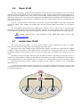
Super VLAN.......................................................................................................................4-70
4.7
Isolate-User-VLAN .............................................................................................................4-70
4.8
VLAN interface type ...........................................................................................................4-71
4.9
Default VLAN .....................................................................................................................4-71
4.10
VLAN configuration ............................................................................................................4-71
4.10.1
4.10.2
4.10.3
4.10.4
4.10.5
4.10.6
4.10.7
4.10.8
VLAN configuration list...................................................................................... 4-71
Create/delete VLAN .......................................................................................... 4-72
Add/delete VLAN interface ............................................................................... 4-72
Specify/restore VLAN description ..................................................................... 4-73
Configure interface type.................................................................................... 4-73
Configure interface default vlan ID ................................................................... 4-73
Configure tag vlan............................................................................................. 4-73
Display VLAN information................................................................................. 4-74
4.11
PVLAN...............................................................................................................................4-74
4.12
GVRP configuration ...........................................................................................................4-74
4.12.1
Brief introduction of GVRP................................................................................ 4-74
4.12.2
GARP ................................................................................................................ 4-74
4.12.3
GVRP ................................................................................................................ 4-77
4.12.4
GVRP Configuration list .................................................................................... 4-77
4.12.5
Enable/disable global GVRP ............................................................................ 4-77
4.12.6
Enable/disable GVRP on a port........................................................................ 4-77
4.12.7
Display GVRP ................................................................................................... 4-78
4.12.8
Add/delete vlan that can be dynamic learnt by GVRP ..................................... 4-78
4.12.9
Display vlan that can be learnt by GVRP ......................................................... 4-78
4.12.10 Examples for GVRP configuration .................................................................... 4-79
4.13 QinQ configuration .............................................................................................................4-79
4.13.1
Brief introduction of QinQ.................................................................................. 4-79
4.13.2
Introduction to QinQ .......................................................................................... 4-79
4.13.3
Implementations of QinQ .................................................................................. 4-80
4.13.4
Adjustable TPID Value of QinQ Frames ........................................................... 4-80
4.13.5
QinQ configuration list....................................................................................... 4-81
4.13.6
Configure global QinQ ...................................................................................... 4-81
4.13.7
Configure QinQ mode of interface.................................................................... 4-81
4.13.8
Configure interface dynamic QinQ.................................................................... 4-82
4.13.9
Enable/disable vlan-swap ................................................................................. 4-82
4.13.10 Configure global vlan-swap .............................................................................. 4-83
4.13.11 Configure rewrite-outer-vlan ............................................................................. 4-83
4.13.12 Display dynamic QinQ ...................................................................................... 4-83
4.13.13 Display vlan-swap ............................................................................................. 4-84
4.13.14 Display rewrite-outer-vlan ................................................................................. 4-84
Chapter 5
Multicast Protocol Configuration...................................................................................... 5-85
5.1
Multicast overview..............................................................................................................5-85
5.2
5.1.1
Multicast Address.............................................................................................. 5-85
GMRP Overview ................................................................................................................5-87
1-4
5.3
GMRP Configuration ..........................................................................................................5-88
5.3.1
5.3.2
5.3.3
5.3.4
5.3.5
5.3.6
5.4
5.5
5.6
Chapter 6
GMRP Configuration list ................................................................................... 5-88
Enable/disable global GMRP............................................................................ 5-88
Enable/disable GMRP on a port ....................................................................... 5-88
Display GMRP................................................................................................... 5-89
Add/delete multicast that can be dynamic learnt by GMRP ............................. 5-89
Display multicast that can be learnt by GMRP ................................................. 5-89
IGMP Snooping Configuration ............................................................................................5-90
5.4.1
IGMP Snooping Overview................................................................................. 5-90
5.4.2
Basic Concepts in IGMP Snooping................................................................... 5-90
5.4.3
How IGMP Snooping Works ............................................................................. 5-92
5.4.4
Processing of Multicast Protocol Messages ..................................................... 5-93
5.4.5
Protocols and Standards................................................................................... 5-96
5.4.6
IGMP Snooping configuration........................................................................... 5-96
5.4.7
IGMP Snooping multicast interface aging time configuration........................... 5-96
5.4.8
IGMP Snooping max-response-time configuration........................................... 5-97
5.4.9
IGMP Snooping interface fast-leave configuration ........................................... 5-97
5.4.10
Configure the number of the multicast group allowed learning ........................ 5-97
5.4.11
IGMP Snooping permit/deny group configuration............................................. 5-97
5.4.12
IGMP Snooping route-port forward configuration............................................. 5-98
5.4.13
Enable/disable IGMP Snooping querier............................................................ 5-98
5.4.14
Configure IGMP Snooping query-interval......................................................... 5-98
5.4.15
Configure IGMP Snooping querier vlan............................................................ 5-99
5.4.16
Configure IGMP Snooping query max response .............................................. 5-99
5.4.17
Configure IGMP Snooping query source IP ..................................................... 5-99
5.4.18
Configure IGMP Snooping route port aging ..................................................... 5-99
5.4.19
Add IGMP Snooping route port....................................................................... 5-100
Static Multicast Configuration ...........................................................................................5-100
5.5.1
Brief introduction of Static Multicast................................................................ 5-100
5.5.2
Static Multicast Configuration ......................................................................... 5-100
5.5.3
Create multicast group.................................................................................... 5-101
5.5.4
Add interfaces to multicast group ................................................................... 5-101
5.5.5
Display multicast group information................................................................ 5-101
5.5.6
Delete interface members from multicast group............................................. 5-102
5.5.7
Delete multicast group .................................................................................... 5-102
Cross-VLAN multicast Configuration ................................................................................5-102
5.6.1
Brief Introduction of Cross-Vlan multicast ...................................................... 5-102
5.6.2
Cross-VLAN Multicast Configuration .............................................................. 5-102
5.6.3
Enable/disable cross-vlan multicast................................................................ 5-103
5.6.4
Configure tag/untag attribution of multicast packet transmission and
vlan-id of the tagged attribution ....................................................................................... 5-103
5.6.5
Display cross-vlan multicast ........................................................................... 5-103
DHCP Configuration ...................................................................................................... 6-104
6.1
Brief introduction of DHCP ...............................................................................................6-104
6.2
Introduction to DHCP .......................................................................................................6-104
6.3
DHCP IP Address Assignment..........................................................................................6-105
6.4
6.3.1
IP Address Assignment Policy ........................................................................ 6-105
6.3.2
Obtaining IP Addresses Dynamically.............................................................. 6-105
6.3.3
Updating IP Address Lease ............................................................................ 6-106
DHCP Packet Format.......................................................................................................6-106
1-5
6.5
DHCP Packet Processing Modes .....................................................................................6-107
6.6
Protocols and Standards ..................................................................................................6-108
6.7
DHCP Relay Agent...........................................................................................................6-108
6.7.1
6.7.2
6.7.3
6.8
DHCP relay Configuration list ........................................................................................... 6-111
6.8.1
6.8.2
6.9
Introduction to DHCP Snooping...................................................................... 6-112
Configuration DHCP snooping.......................................................................................... 6-113
6.10.1
6.10.2
6.10.3
6.10.4
6.10.5
6.10.6
6.10.7
Chapter 7
Enable DHCP relay..........................................................................................6-111
Configure vlan interface ...................................................................................6-111
DHCP snooping ............................................................................................................... 6-112
6.9.1
6.10
Usage of DHCP Relay Agent .......................................................................... 6-108
DHCP Relay Agent Fundamentals ................................................................. 6-108
Option 82 Supporting ...................................................................................... 6-109
Enable DHCP snooping .................................................................................. 6-113
Configure trust ports ....................................................................................... 6-113
Configure max host number ........................................................................... 6-113
Configure IP source guard .............................................................................. 6-114
Show DHCP snooping of ports ....................................................................... 6-114
Show DHCP snooping configuration of VLANs .............................................. 6-114
Show information of clients ............................................................................. 6-114
ARP Configuration (Dynamic ARP Inspection) ............................................................. 7-115
7.1
Brief Introduction of ARP .................................................................................................. 7-115
7.2
ARP configuration ............................................................................................................ 7-115
7.2.1
7.2.2
7.2.3
7.2.4
7.2.5
7.2.6
7.2.7
7.2.8
7.2.9
7.2.10
7.2.11
7.2.12
7.2.13
Chapter 8
8.1
8.2
8.3
Display ARP table item.................................................................................... 7-115
Enable/disable ARP anti-flood attack.............................................................. 7-116
Configure deny action and threshold of ARP anti-flood.................................. 7-116
Configure ARP anti-flood recover-time......................................................... 7-116
ARP anti-flood MAC recover........................................................................... 7-117
Display ARP anti-flood attack information.................................................... 7-117
Bind blackhole mac generated by arp anti-flood to be general ...................... 7-117
Enable/disable ARP anti-spoofing .................................................................. 7-118
Configure unknown ARP packet handling strategy ........................................ 7-118
Enable/disable ARP anti-spoofing valid-check ............................................... 7-119
Enable/disable ARP anti-spoofing deny-disguiser.......................................... 7-119
Display ARP anti-spoofing............................................................................ 7-119
Configure trust port of ARP anti-attack ........................................................... 7-120
ACL Configuration ......................................................................................................... 8-121
ACL Overview..................................................................................................................8-121
8.1.1
ACL Match Order ............................................................................................ 8-121
8.1.2
Ways to Apply ACL on a Switch...................................................................... 8-122
8.1.3
ACLs Based on Time Ranges......................................................................... 8-122
Configuring ACL...............................................................................................................8-123
8.2.1
Matching order configuration .......................................................................... 8-123
8.2.2
ACL support .................................................................................................... 8-123
ACL configuration.............................................................................................................8-124
8.3.1
Configuration list ............................................................................................. 8-124
8.3.2
Configure time range ...................................................................................... 8-124
8.3.3
Standard ACL .................................................................................................. 8-125
8.3.4
Define extended ACL ...................................................................................... 8-126
1-6
8.3.5
8.3.6
8.3.7
8.4
Chapter 9
Define layer 2 ACL .......................................................................................... 8-127
User-defined ACL............................................................................................ 8-128
Activate ACL.................................................................................................... 8-129
Monitor and maintanence of ACL......................................................................................8-129
QOS Configuration ........................................................................................................ 9-131
9.1
Brief introduction of QOS .................................................................................................9-131
9.2
QOS Configuration...........................................................................................................9-133
9.2.1
QoS Configuration list ..................................................................................... 9-133
9.2.2
Packet redirection configuration ..................................................................... 9-133
9.2.3
Priority configuration ....................................................................................... 9-133
9.2.4
Queue-scheduler configuration....................................................................... 9-134
9.2.5
The cos-map relationship of hardware priority queue and priority of
IEEE802.1p protocol........................................................................................................ 9-134
9.2.6
Flow mirror configuration ................................................................................ 9-135
9.2.7
Flow statistic configuration.............................................................................. 9-135
9.2.8
Traffic rewrite vlan configuration ..................................................................... 9-135
9.2.9
Traffic-insert-vlan configuration....................................................................... 9-136
9.3
Monitor and maintenance of QoS .....................................................................................9-136
9.4
Port isolation ....................................................................................................................9-137
9.5
9.4.1
Brief introduction of port isolation ................................................................... 9-137
9.4.2
Port isolation configuration.............................................................................. 9-137
Strom control....................................................................................................................9-138
9.5.1
Brief introduction of strom control ................................................................... 9-138
9.5.2
Strom control configuration ............................................................................. 9-138
Chapter 10
10.1
STP Configuration ....................................................................................................... 10-139
Brief introduction of STP Configuration...........................................................................10-139
10.1.1
Introduction to STP ....................................................................................... 10-139
10.1.2
Introduction to MSTP .................................................................................... 10-146
10.1.3
Protocols and Standards............................................................................... 10-151
10.2 STP Configuration..........................................................................................................10-152
10.2.1
STP Configuration list ................................................................................... 10-152
10.2.2
Enable/disable STP ...................................................................................... 10-152
10.2.3
Enable/disable interface STP ....................................................................... 10-152
10.2.4
Configure STP priority................................................................................... 10-153
10.2.5
Configure switch Forward Delay................................................................... 10-153
10.2.6
Configure Hello Time .................................................................................... 10-154
10.2.7
Configure Max Age ....................................................................................... 10-154
10.2.8
Configure path cost of specified interfaces................................................... 10-154
10.2.9
Configure STP priority od specified port....................................................... 10-155
10.2.10 Configure spanning-tree root-guard.............................................................. 10-155
10.2.11 Configure interface to force to send rstp packet........................................... 10-155
10.2.12 Configure link type of specified interface...................................................... 10-156
10.2.13 Configure the current port as an edge port................................................... 10-156
10.2.14 Configure the speed limit of sending BPDU of specified interface............... 10-156
10.2.15 STP monitor and maintainenance ................................................................ 10-157
10.2.16 Enable/disable STP remote-loop-detect....................................................... 10-158
10.3 Brief Introduction of MSTP .............................................................................................10-158
10.4
MSTP Configuration.......................................................................................................10-158
10.4.1
MSTP configuration list ................................................................................. 10-158
1-7
10.4.2
10.4.3
10.4.4
10.4.5
10.4.6
10.4.7
10.4.8
10.4.9
10.4.10
10.4.11
10.4.12
Chapter 11
Configure MSTP timer parameter................................................................. 10-159
Configure MSTP configuration mark............................................................. 10-159
Configure MSTP netbridge priority ............................................................... 10-160
Configure MSTP interface edge interface status.......................................... 10-160
Configure MSTP interface link type .............................................................. 10-160
Configure MSTP interface path cost............................................................. 10-160
Configure MSTP interface priority................................................................. 10-161
Configure spanning-tree mst root-guard....................................................... 10-161
Display MSTP configuration information....................................................... 10-161
Enable/disable digest snooping .................................................................... 10-162
Configure Ignore of VLAN............................................................................. 10-162
802.1X Configuration Command ................................................................................. 11-163
11.1
Brief introduction of 802.1X configuration ....................................................................... 11-163
11.2
802.1X Configuration ..................................................................................................... 11-163
11.2.1
AAA configuration mode ............................................................................... 11-163
11.2.2
RADIUS Server Configuration ...................................................................... 11-163
11.2.3
Domain Configuration ................................................................................... 11-165
11.2.4
802.1X Configuration .................................................................................... 11-167
Chapter 12
SNTP Client Configuration .......................................................................................... 12-169
12.1
Brief introduction of SNTP protocol.................................................................................12-169
12.2
SNTP client configuration...............................................................................................12-169
12.2.1
12.2.2
12.2.3
12.2.4
12.2.5
12.2.6
12.2.7
12.2.8
12.2.9
Chapter 13
Enable/disable SNTP client .......................................................................... 12-169
SNTP client working mode configuration...................................................... 12-170
SNTP client unicast server configuration...................................................... 12-170
SNTP client broadcast delay configuration................................................... 12-170
SNTP client multicast TTL configuration....................................................... 12-170
SNTP client poll interval configuration .......................................................... 12-171
SNTP client retransmit configuration ............................................................ 12-171
SNTP client valid server configuration.......................................................... 12-171
SNTP client MD5 authentication configuration ............................................. 12-172
Syslog Configiration..................................................................................................... 13-173
13.1
Brief introduction of Syslog.............................................................................................13-173
13.2
Syslog Configiration .......................................................................................................13-173
13.2.1
13.2.2
13.2.3
13.2.4
13.2.5
13.2.6
13.2.7
13.2.8
13.2.9
Chapter 14
Enable/disable Syslog................................................................................... 13-174
Syslog sequence number configuration ....................................................... 13-174
Syslog time stamps configuration ................................................................. 13-174
Syslog terminal outputting configuration....................................................... 13-174
Syslog logging buffered outputting configuration.......................................... 13-175
Syslog Flash storage outputting configuration.............................................. 13-176
Syslog logging host outputting configuration ................................................ 13-176
Syslog SNMP Agent outputting configuration............................................... 13-177
Module debug configuration ......................................................................... 13-178
SSH Configuration....................................................................................................... 14-179
14.1
Brief introduction of SSH ................................................................................................14-179
14.2
SSH Configuration .........................................................................................................14-179
14.2.1
14.2.2
14.2.3
Enable/disable SSH function of the device................................................... 14-179
SSH key configuration .................................................................................. 14-179
Others............................................................................................................ 14-180
1-8
Chapter 15
LLDP configuration ...................................................................................................... 15-182
15.1
Brief introduction of LLDP protocol .................................................................................15-182
15.2
Introduction to LLDP ......................................................................................................15-182
15.2.1
15.3
LLDP configuration.........................................................................................................15-183
15.3.1
15.3.2
15.3.3
15.3.4
15.3.5
15.3.6
Chapter 16
LLDP Overview ............................................................................................. 15-182
LLDP configuration list .................................................................................. 15-183
Enable/disable global LLDP.......................................................................... 15-183
Configure LLDP hello-time............................................................................ 15-183
Configure LLDP hold-time............................................................................. 15-184
Interface LLDP packet receiving/sending mode configuration ..................... 15-184
Display LLDP information ............................................................................. 15-184
ERRP Command Configuration .................................................................................. 16-186
16.1
Brief introduction of ERRP..............................................................................................16-186
16.2
ERRP Overview .............................................................................................................16-186
16.3
Basic Concepts in ERRP................................................................................................16-186
16.3.1
ERRP domain ............................................................................................... 16-186
16.3.2
ERRP ring ..................................................................................................... 16-187
16.3.3
Control VLAN and data VLAN ...................................................................... 16-187
16.3.4
Node.............................................................................................................. 16-187
16.3.5
Primary port and secondary port .................................................................. 16-187
16.3.6
Common port and edge port......................................................................... 16-188
16.3.7
Multi-domain intersection common port........................................................ 16-188
16.3.8
Timers ........................................................................................................... 16-188
16.3.9
ERRP Packets .............................................................................................. 16-189
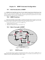
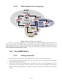
16.4 Typical ERRP Networking ..............................................................................................16-189
16.4.1
Single ring ..................................................................................................... 16-189
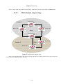
16.4.2
Multi-domain tangent rings............................................................................ 16-190
16.4.3
Single-domain intersecting rings................................................................... 16-191
16.4.4
Dual homed rings.......................................................................................... 16-191
16.4.5
Multi-domain intersecting rings ..................................................................... 16-192
16.5 How ERRP Works..........................................................................................................16-192
16.5.1
Polling mechanism........................................................................................ 16-192
16.5.2
Link down alarm mechanism ........................................................................ 16-193
16.5.3
Ring recovery................................................................................................ 16-193
16.5.4
Broadcast storm suppression mechanism in a multi-homed subring in
case of primary ring link failure...................................................................................... 16-193
16.5.5
Protocols and Standards............................................................................... 16-193
16.6 ERRP Configuration.......................................................................................................16-193
16.6.1
ERRP Configuration list ................................................................................ 16-193
16.6.2
ERRP configuration....................................................................................... 16-194
16.6.3
Configure ERRP timer .................................................................................. 16-194
16.6.4
Enter ERRP configuration mode................................................................... 16-194
16.6.5
Configure control-vlan of ERRP domain....................................................... 16-194
16.6.6
Create ERRP ring ......................................................................................... 16-195
16.6.7
Enable/disable ERRP ring ............................................................................ 16-196
16.6.8
Display ERRP domain and ring information ................................................. 16-196
Chapter 17
PPPoE Plus Configuration .......................................................................................... 17-197
17.1
Brief Introduction of PPPoE Plus ....................................................................................17-197
17.2
PPPoE Plus Configuration..............................................................................................17-197
1-9
17.2.1
17.2.2
17.2.3
Chapter 18
PPPoE Plus Configuration list ...................................................................... 17-197
Enable/disable PPPoE Plus.......................................................................... 17-197
Configure PPPoE Plus type .......................................................................... 17-198
CFM Configuration ...................................................................................................... 18-199
18.1
Brief introduction of CFM................................................................................................18-199
18.2
Connectivity fault management overview........................................................................18-199
18.3
Basic Concepts in Connectivity Fault Detection ..............................................................18-199
18.3.1
18.3.2
18.3.3
18.3.4
18.3.5
18.4
Maintenance domain..................................................................................... 18-199
Maintenance association .............................................................................. 18-199
Maintenance point......................................................................................... 18-199
Basic Functions of Connectivity Fault Management .................................... 18-201
Protocols and Standards............................................................................... 18-201
CFM Configuration.........................................................................................................18-201
18.4.1
18.4.2
18.4.3
18.4.4
18.4.5
18.4.6
18.4.7
18.4.8
18.4.9
18.4.10
18.4.11
18.4.12
18.4.13
18.4.14
CFM Configuration list .................................................................................. 18-201
Configure cfm domain................................................................................... 18-202
Configure cfm mep level ............................................................................... 18-202
Configure cfm mip level ................................................................................ 18-203
Configure remote cfm rmep level.................................................................. 18-203
Configure cfm cc interval .............................................................................. 18-203
Enable/disable VLAN sending cfm cc enable level ...................................... 18-204
cfm ping......................................................................................................... 18-204
cfm traceroute ............................................................................................... 18-205
Display cfm domain....................................................................................... 18-205
Display cfm maintenance-points local .......................................................... 18-205
Display cfm maintenance-points remote ...................................................... 18-206
Display cfm cc database ............................................................................... 18-206
Display cfm errors ......................................................................................... 18-207
1-10
Chapter 1 Accessing Switch
This chapter is the basic knowledge for system management, including:
·
Command line interface
·
Command syntax comprehension
·
Syntax help
·
History command
·
Symbols in command
·
Parameter in command
·
User management
·
Ways for switch management
1.1
Command Line Interface
System provides a series of configuration command and command line interface. User can configure and
manage switch by command line. Command line interface has the features as following:
·
Local configuration by Console interface
·
Local or remote configuration by TelNet
·
Configure command classification protection to guarantee unauthorized user illegal accessing.
·
Input “?”at any moment to obtain help information
·
Provide such network test command as ping to diagnose network fault
·
Provide FTP, TFTP, Xmodem to download and upload files
·
Keywords partial matching searching is adopted by command line convertor for user to input
non-conflicting key words, such as: interface command can only input “interf”
1.1.1
Command Line Configuration Mode
System command line adopts classification protection to prevent illegal accessing of unauthorized user. Each
command mode is for different configuration with the connection and distinction. For example, after successful
accessing, user of all level can enter common user mode which can only see the system operation information;
administrator can input “enable” to enter privileged mode; input “configure terminal” to enter global configuration
mode from privileged mode which can enter related configuration mode according to inputting different
configuration command. For example:
Command line provides command mode as following:
·
User mode
·
Privileged mode
·
Global configuration mode
·
Interface configuration mode
·
VLAN configuration mode
·
AAA configuration mode
1-11
·
RADIUS configuration mode
·
Domain configuration mode
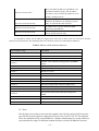
The function and details of each command mode are as following:
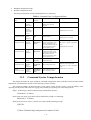
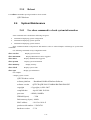
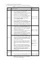
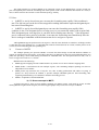
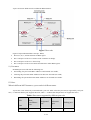
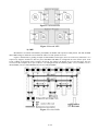
Table 1. Command Line Configuration Mode
Command line
mode
Function
Prompt
character
Command for entering
Command for exiting
User mode
See switch
operation
information
QTECH>
Connect with switch after
inputting user name and
password
exit disconnect with switch
Privileged mode
See switch
operation
information
and manage
system
QTECH#
Input enable in user mode
exit return to user mode
Global
configuration mode
Configure
global
parameter
QTECH(con
fig)#
Input configure terminal in
privileged mode
exit, end return to privileged mode
Interface
configuration mode
Configure
interface
parameter
QTECH(con
fig-if-etherne
t-0/1)#
Input “interface Ethernet 0/1”
in global configuration mode,
interface configuration can
enter other interface mode and
VLAN configuration mode
without inputting “exit”.
end return to privileged mode
quit disconnect with switch
VLAN
configuration mode
Configure
VLAN
parameter
QTECH(con
fig-if-vlan)#
Input “vlan 2” in global
configuration mode, VLAN
configuration mode can enter
other VLAN mode and
interface configuration mode
without inputting “exit”.
AAA configuration
mode
Create
domain
QTECH(con
fig-aaa)#
Input “aaa” in global
configuration mode
RADIUS
configuration mode
Configure
RADIUS
server
parameter
QTECH(con
fig-radius-de
fault)#
Input “radius host default” in
global configuration mode
Configure
domain
parameter
QTECH(con
fig-aaa-test.c
om)#
Input “domain test.com” in
AAA configuration mode
Domain
configuration mode
1.1.2
quit disconnect with switch
exit return to global configuration
mode
quit disconnect with switch
end return to privileged mode
exit return to AAA configuration
mode
quit disconnect with switch
Command Syntax Comprehension
This chapter describes the steps needed for command configuration. Please read this section and related detail
information of command line interface in the following sections carefully.
The logging in identity verification of the system console of this switch is used to verify the identity of the
operating user. It permits and refuses the logging in by matching recognizing user name and password.
Step 1. Following are showed when entering command line interface,
Username(1-32 chars):
Please input user name, press Enter button, and then the prompt is as following:
Password (1-16 chars):
Input password. If it is correct, enter the user mode with the following prompt:
QTECH>
& Note: Defaulted login and password is admin/123456.
1-12
In switch system, there are 2 different privileges. One is administrator, and the other is common user.
Common user only can see the configuration information of switch without right to modify it but administrator can
manage and configure the switch by specified command.
Logging in as administrator can enter privileged mode from user mode.
QTECH>enable
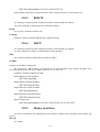
Step 2: Input command
Skip to step 3, if the command needs input the parameter. Continue this step if the command need input the
parameter.
If the command needs a parameter, please input it. When inputting a parameter, keyword is needed.
The parameter of the command is specified which is the number or character string or IP address in a certain
range. Input “?” when you are uncomprehending, and input the correct keyword according to the prompt. Keyword is
what is to be operated in command.
If more than one parameter are needed, please input keywords and each parameter in turn according to the
prompt until “<enter>”is showed in prompt to press enter button.
Step 3: Press enter button after inputting complete command.
For example:
! User need not input parameter
QTECH#quit
“quit” is a command without parameter. The name of the command is quit. Press enter button after inputting
it to execute this command.
! User need input parameter
QTECH(config)#vlan 3
“vlan 3”is a command with parameter and keyword, vlan of which is command keyword and 3 of which is
parameter.
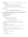
1.1.3
Syntax Help
There is built-in syntax help in command line interface. If you are not sure about the syntax of some
command, obtain all command and its simple description of the current mode by inputting “?” or help command;
list all keywords beginning with the current character string by inputting “?” closely after the command character
string; input “?” after space, if “?” is in the same location of the keyword, all keywords and its simple description
will be listed, if “?”is in the same location of parameter, all the parameter description will be listed, and you can
continue to input command according to the prompt until the prompt command is “
〈enter〉
” to press enter button to
execute command.
For example:
Directly input “?”in privileged mode
QTECH#?
System mode commands:
cls clear screen
help description of the interactive help
ping ping command
quit disconnect from switch and quit
……
Input “?” closely after keyword
1-13
QTECH(config)#interf?
interface
Input “?”after command character string and space
QTECH(config)#spanning-tree ?
forward-time config switch delaytime
hello-time
max-age
config switch hellotime
config switch max agingtime
priority
config switch priority
<enter>
The command end.
· Parameter range and form
QTECH(config)#spanning-tree forward-time ?
INTEGER<4-30> switch delaytime: <4-30>(second)
· Command line end prompt
QTECH(config)#spanning-tree ?
<enter> The command end.
1.1.4
History command
Command line interface will save history command inputted by user automatically so that user can invoke
history command saved by command line interface and re-execute it. At most 100 history commands can be saved by
command line interface for each user. Input “Ctrl+P” to access last command, and “Ctrl+N” for next command.
1.1.5
Symbols in command
There are all kinds of symbols in command syntax which is not a part of command but used to describe how
to input this command. Table 1-2 makes a brief description of these symbols.
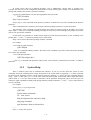
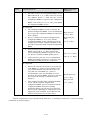
1.2
Command Symbols Description
Symbol
Description
Vertical bars |
Vertical bars (|) means coordinate, together using with braces ({ }) and
square brackets ([ ]).
Square brackets [ ]
Square brackets ([ ]) mean optional elements.
For example:
show vlan [ vlan-id ]
Braces { }
Braces ({ }) group required choices, and vertical bars ( | ) separate the
alternative elements. Braces and vertical bars within square brackets ([{ | }])
mean a required choice within an optional element.
1-14
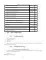
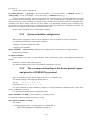
1.2.1
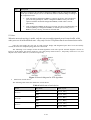
Command Parameter Categories
There are 5 categories command parameter as following:
· Scale
Two numerical value linked by hyphen in angle brackets (< >) means this parameter is some number in the
range of those two numbers.
For example:
INTEGER<1-10> means user can input any integer between 1 and 10 (include 1 and 10), such as 8 is a
valid number.
· IP address
The prompt which is in the form of A.B.C.D. means the parameter is an IP address. A valid IP address is
needed to input.
For example:
192.168.0.100 is a valid IP address.
· MAC address
The prompt which is in the form of H:H:H:H:H:H means the parameter is a MAC address. A valid MAC
address is needed to input. If a multicast MAC address is needed, there will be related prompt.
For example:
01:02:03:04:05:06 is a valid MAC address.
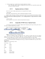
· Interface list
The prompt of interface list is STRING<3-4>. Interface parameter interface-num is in the form of
interface-type + interface-number. Interface-type is Ethernet and interface-number is slot-num/port-num, in which
slot-num is in the range of 0 to 2, and port-num is in the range of 1 to 24. Seriate interfaces with the same type can be
linked by to keyword, but the port number to the right of the to keyword must be larger than the one to the left of the
keyword, and this argument only can be repeated for up to 3 times. The special declaration of interface parameter
interface list will be displayed in the command.
For example:
show spanning-tree interface ethernet 0/1 ethernet 0/3 to ethernet 0/5
means displaying spanning-tree information of interface ethernet 0/1 ethernet 0/3 to ethernet 0/5
· Character string
The prompt which is in the form of STRING<3-4> means the parameter is a character string which is in the
form of 1 to 19 characters. “?”can be inputted to display the concrete command description.
1.3
User management
There are 2 privileges for user:
· administrator
· normal user
Normal user can only enter user mode not privileged mode after logging in, so that he can only see system
information but not to configure it. Administrator has the right to enter all modes, and query and configure all
parameters.
1-15
1.3.1
System default user name
There is a system default built-in user name called admin, and the initial password is 123456. It is
suggested modifying password when logging in switch for the first time to avoid leaking it. This user name cannot be
deleted and the privilege cannot be modified either. It also possesses the right to manage other users. Please
remember your modified password.
1.3.2
Add user
Log in with the identity of system administrator admin to enter privileged mode, then global configuration
mode by using username command. Input user name, user’s privilege, password to add new user according to system
prompt or by using the following command.
username username [ privilege level ] { password encryption-type password }
username:User name of new users and existed users ranges from 1 to 32 printable characters excluding such
wildcards as '/', ':', '*', '?', '\\', '<', '>', '|', '"' etc.
privilege:Privilege of new user ranges from 0 to 15. 0 to 1 means user while 2 to 15 means administrator.
encryption-type: the value of it is 0 or 7. 0 means non-encryption and 7 means encryption (It is not supported
now).
password:Log in password for new user and modified password of the existed user ranges from 1 to 16
characters or numbers.
If the privilege doesn’t configure, the default privilege is ordinary user. At most 8 users are supported.
Caution: User name supports case insensitivity while password doesn’t support case sensitivity.
! Add a new administrator “red”, configure privilege to be 3, and password to be 1234
QTECH(config)#username red privilege 3 password 0 1234
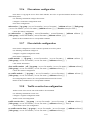
1.3.3
Modify password
In global configuration mode, system administrator admin can use the following command to modify
password of his or other user. Other user can only modify his own password.
username change-password
For example:
! Modify the password of user “red” to be 123456
QTECH(config)#username change-password
please input you login password : ******
please input username :red
Please input user new password :******
Please input user comfirm password :******
change user red password success.
1-16
1.3.4
Modify privilege
In global configuration mode, only administrator admin can use following command to modify the privilege
of other user.
username username [ privilege level ] { password encryption-type password }
username:User name of new users and existed users ranges from 1 to 32 printable characters excluding such
wildcards as '/', ':', '*', '?', '\\', '<', '>', '|', '"' etc.
privilege:Privilege of new user or the modified privilege of existed user ranges from 0 to 15. 0 to 1 means user
while 2 to 15 means administrator. Caution: the privilege of administrator cannot be modified.
encryption-type: the value of it is 0 or 7. 0 means non-encryption and 7 means encryption (It is not supported
now).
password:Log in password for new user and modified password of the existed user ranges from 1 to 16
characters or numbers.
If inputting nothing to modify the privilege of existed user, the privilege doesn’t modify.
& Caution: User name supports case insensitivity while password doesn’t support case
sensitivity.
For example:
! Modify the privilege of administrator “red” to be 1, and password to be 1234
QTECH(config)#username red privilege 1 password 0 1234
1.3.5
Remove user name
System administrator admin can use following command to remove user name in global configuration mode
no username username
Username is the user name to be deleted.
For example:
! Remove user red
QTECH(config)#no username red
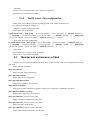
1.3.6
View system user information
View user list, and input
show username
command or
show username [ username ]
command in any configuration mode to display information of all users.
For example:
! Display information of user red
QTECH(config)#show username red
display user information
user name
role
1-17
____________________________________________________________
red
1.4
ADMIN
Remote authentication of administrator
After authentication, user’s default privilege is normal user. Only when there is Service-Type field in
authentication accepting packet the value of which is Administrative, user’s privilege is administrator.
Caution: Admin user only supports local database authentication.
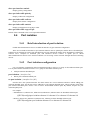
1.4.1
Start RADIUS remote authentication
Use following command in globa configuration mode:
muser { local | { radius radiusname { pap | chap } [ local ] } }
It can be configured to authenticate only by RADIUS remote authentication or by local database
authentication after no response of RADIUS server caused by failing connection.
1.4.2
Display authentication configuration
Use following command to display authentication configuration.
show muser
1.5
Ways of managing switch
System provides following ways of management:
· By hyper terminal accessing command-line interface(CLI)
· By telnet managing system
· By SNMP managing software management system
· By Web browser such as Internet Explorer managing system
1.5.1
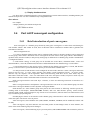
Manage switch by hyper terminal
Use hyper terminal (or simulation terminal software) connect to Console to access system command line
interface (CLI) by hyper terminal.
Configuration: Open “file” -> “attribute” menu, popping up a window. Enter configuration to restore it to
default value, and click “setting” and then choose “auto-detect” in the pulldown list of “terminal simulation” and
click [ok]. After the successful connection and seeing logging in interface of operation system in terminal, configure
switch by command line interface. The steps are as following:
Step 1: Connect switch Console with computer serial port;
Step 2: After the switch power on and system successful booting, logging in prompt can be seen:
Username(1-32 chars):
1-18
Step 3: Input correct user name, press enter button, then input corresponding password. If it is the first time
to logging in switch, use default user name admin and its password 123456 to log in and operate as system
administrator. If your own user name and password exist, log in with your own user name and password;
Step 4: After successfully logging in, following information is displayed:
QTECH>
Step 5: As administrator, after entering privileged mode, use copy running-config startup-config command to
save configuration.
QTECH#copy running-config startup-config
When following information is displayed:
Startup config in flash will be updated, are you sure(y/n)? [n]y
Building, please wait...
It means system is saving configuration. Please wait, then the prompt is:
Build successfully.
It means current configuration is saved successfully.
Following information is displayed when system booting:
Ready to load startup-config, press ENTER to run or CTRL+C to cancel:
Press enter button to make saved configuration be effective, and press CTRL+C to restore system default
configuration.
Step 6: Administrator can use stop connection when overtime, while normal user can use this function in user
mode. Input timeout command to configure the overtime of user’s logging in to be 20 minutes. And use no timeout
command to configure overtime to be non-over timing.
Step 7: Input following command after finishing operation to switch:
QTECH#quit
It is used to exit user interface.
1.5.2
Manage switch by telnet
Step 1: Establish configuration environment by connecting computer by network to switch interface;
Step 2: Run Telnet program in computer;
Step 3: After switch is power on, input switch IP address to connect to switch, and input configured logging
in password according to the prompt, then the command line prompt is displayed (such as QTECH>). It will be
disconnected after 1 minute when there is not any input before successfully logging in or wrong inputting of user
name and password for 5 times. If there is such prompt as “Sorry, session limit reached.”, please connect later (At
most 2 telnet users are allowed to log in at the same time.);
Step 4: Use related command to configure switch system parameter or view switch operation. If you want to
enter privileged mode, user must possess the privilege of administrator. If you need any help, please input “?”at any
moment. For concrete command, please refer to following chapters.
1-19
Step 5: If you want to exit telnet, use quit or exit command to exit in user mode, and quit command to exit in
other mode. Administrator can use stop username command in privileged mode to exit logging in.
1-20
Chapter 2 Switch Manage and Maintenance
2.1
Configuration Files Management
2.1.1
Edit configuration files
Configuration files adopts text formatting which can be upload to PC from devices by FTP and TFTP
protocol. Use text edit tool (such as windows nootbook) to edit uploaded configuration files.
System is defaulted to execute configuration files in global configuration mode, so there are two initial
commands: “enable”, and “configure terminal”. There is entering symbol after each command.
2.1.2
Modify and save current configuration
User can modify and save system current configuration by command line interface to make current
configuration be initial configuration of system next booting.
copy running-config startup-config
This command is needed to save current configuration. When executing configuration files, if there is un-executed
command, it will be displayed as “[Line:xxxx]invalid: commandString”. If there is command with executing failure,
it will be displayed as “[Line:xxxx]failed: commandString”. If there is a command beyond 512 characters, it will be
displayed as “[Line:xxxx]failed: too long command: commandString”, and only first 16 characters of this command
will be displayed, and end up with …, in which “xxxx”means the line number of the command, and commandString
means command character string. Un-executive command includes command with grammar fault and un-matching
pattern. Use following command in privileged mode.
QTECH#copy running-config startup-config
2.1.3
Erase configuration
Use clear startup-config command to clear saved configuration. After using this command to clear saved
configuration and reboot switch. The switch will restore to original configuration. Use this command in privileged
mode.
QTECH#clear startup-config
2.1.4
Execute saved configuration
User can restore saved configuration by commang line interface by using copy startup-config running-config
command in privileged mode to execute saved configuration.
QTECH#copy startup-config running-config
2.1.5
Display saved configuration
User can display syatem saved configuration information in the form of text by command line interface. Use
following command to display system saved configuration:
2-21
show startup-config [ module-list ]
module-list: Optional module. If the module name is unoptioned, all information of configuration files will be
displayed. If choose one or same of the modules, the specified information will be displayed. This command can be
used in any configuration mode.
For example:
! Display all saved configuration
QTECH#show running-config
! Display saved configuration of GARP and OAM module
QTECH#show running-config garp oam
2.1.6
Display current configuration
User can display syatem current configuration information in the form of text by command line interface. Use
following command to display system current configuration:
show running-config [ module-list ]
module-list: Optional module. If the module name is unoptioned, all information of configuration files will be
displayed. If choose one or same of the modules, the specified information will be displayed.
For example:
! Display all configurations
QTECH#show running-config
! Display configuration of GARP and OAM module
QTECH#show running-config garp oam
2.1.7
Configure file executing mode shift
User can change executing mode of configuration file by command line interface. System saved configuration
filescan be executed in stop and continue mode. When coming across errors, the executing will not stop; it will
display errors and continue executing. It is defaulted to be non-stop mode. Use buildrun mode stop to configure
executing mode to be stopped. Use buildrun mode continue command to configure buildrun mode to be
continune. Use these commands in privileged mode.
For example:
! Configure buildrun mode to be stop.
QTECH#buildrun mode stop
! Configure buildrun mode to be continune
QTECH#buildrun mode continue
2.2
Online Loading Upgrade Program
System can upgrade application program and load configuration files on line by TFTP, FTP, Xmodem, and can
upload configuration files, logging files, alarm information by TFTP and FTP.
2-22
2.2.1
Upload and download files by TFTP
Use following command to upload files by TFTP:
upload { alarm | configuration | logging } tftp tftpserver-ip filename
Use following command to download files by TFTP:
load {application | configuration | whole-bootrom } tftp tftpserver-ip filename
tftpserver-ip is the IP address of TFTP server. Filename is the file name to be loaded which cannot be system
key words (such as con cannot be file name in windows operation system). Open TFTP server and set file upload
path before use this command.
Suppose IP address of TFTP server is 192.168.0.100, file name is abc. Open TFTP server to configure upload
and download path in privileged mode.
For example:
! Upload configuration to 192.168.0.100 by FTP and saved as abc
QTECH#upload configuration ftp 192.168.0.100 abc username password
Configuration information saved when uploading is successful.
! Download configuration program abc to 192.168.0.100 by TFTP
QTECH#load configuration ftp 192.168.0.100 abc
Reboot the switch after successful download and run new configuration program.
! Upload alarm to 192.168.0.100 by TFTP and saved as abc
QTECH#upload alarm tftp 192.168.0.100 abc
! Upload logging to 192.168.0.100 by TFTP and saved as abc
QTECH#upload logging tftp 192.168.0.100 abc
! Download application program app.arj to 192.168.0.100 by TFTP
QTECH#load application tftp 192.168.0.100 app.arj
Reboot the switch after successful download and run new application program.
! Download whole-bootrom abc to 192.168.0.100 by TFTP
QTECH#load whole-bootrom tftp 192.168.0.100 rom3x26.bin
2.2.2
Upload and download files by FTP
Use following command to upload files by FTP:
upload { alarm | configuration | logging } ftp ftpserver-ip filename username userpassword
Use following command to download files by FTP:
load { application | configuration | whole-bootrom} ftp ftpserver-ip filename username userpassword
ftpserver-ip is the IP address of FTP server. Filename is the file name to be loaded which cannot be system key
words (such as con cannot be file name in windows operation system). Open FTP server and set username, password
and file upload path before use this command.
Suppose IP address of TFTP server is 192.168.0.100, file name is abc. Open TFTP server to configure
username to be user, password to be 1234 and file download path in privileged mode.
For example:
! Upload configuration to 192.168.0.100 by FTP and saved as abc
2-23
QTECH#upload configuration ftp 192.168.0.100 abc user 1234
Configuration information saved when uploading is successful.
! Download configuration program abc to 192.168.0.100 by FTP
QTECH#load configuration ftp 192.168.0.100 abc user 1234
Reboot the switch after successful download and run new configuration program.
! Download application program abc to 192.168.0.100 by FTP
QTECH#load application ftp 192.168.0.100 abc user 1234
Reboot the switch after successful download and run new application program.
! Upload alarm to 192.168.0.100 by FTP and saved as abc
QTECH#upload alarm ftp 192.168.0.100 abc user 1234
! Upload logging to 192.168.0.100 by FTP and saved as abc
QTECH#upload logging ftp 192.168.0.100 abc user 1234
! Download whole-bootrom abc to 192.168.0.100 by FTP
QTECH#load whole-bootrom ftp 192.168.0.100 abc user 1234
2.2.3
Download files by Xmodem
Use load application xmodem command to load application program by Xmodem protocol.
load application xmodem
Input following command in privileged mode:
QTECH#load application xmodem
Choose “send” -> “send file” in super terminal, and input full path and filename of the file in filename dialog
box, and choose Xmodem protocol in “protocol” , then click 【send】.
Reboot the switch after successful download and run new application program.
Use load configuration xmodem command to load configuration program by Xmodem protocol.
load configuration xmodem
Input following command in privileged mode:
QTECH#load configuration xmodem
Choose “send” -> “send file” in super terminal, and input full path and filename of the file in filename dialog
box, and choose Xmodem protocol in “protocol”, then click 【send】.
Reboot the switch after successful download and run new application program.
Use load whole-bootrom xmodem command to load whole bootrom by xmodem protocol.
load whole-bootrom xmodem
Input following command in privileged mode:
QTECH#load whole-bootrom xmodem
Choose “send” -> “send file” in super terminal, and input full path and filename of the file in filename dialog
box, and choose Xmodem protocol in “protocol”, then click 【send】.
Reboot the switch after successful download and run new BootRom program.
2-24
2.3
MAC address table management
2.3.1
Brief
introduction
of
MAC
address
table
management
System maintains a MAC address table which is used to transfer packet. The item of this table contains MAC
address, VLAN ID and interface number of packet entering. When a packet entering switch, switch will look up the
MAC address tablke according to destination MAC and VLAN ID of the packet. If it is found out, send packet
according to the specified interface in the item of MAC address table, or the packet will be broadcasted in this
VLAN. In SVL learning mode, look up the table only according to MAC in packet and neglect VLAN ID.
System possesses MAC address learning. If the source MAC address of the received packet does not existed
in MAC address table, system will add source MAC address, VLAN ID and port number of receiving this packet as a
new item to MAC address table.
MAC address table can be manual configured. Administrator can configure MAC address table according to
the real situation of the network. Added or modified item can be static, permanent, blackhole and dynamic.
System can provide MAC address aging. If a device does not receive any packet in a certain time, system will
delete related MAC address table item. MAC address aging is effective on (dynamic) MAC address item which can
be aging by learning or user configuration.
2.3.2
MAC address table management list
MAC address table management
·
Configure system MAC address aging time
·
Configure MAC address item
·
Enable/disable MAC address learning
·
Modify MAC address learning mode
2.3.3
Configure system MAC address aging time
Use mac-address-table age-time command in global configuration mode to configure MAC address aging
time. Use no mac-address age-time command to restore it to default time.
mac-address-table age-time { agetime | disable }
no mac-address-table age-time
Agetime means MAC address aging time which ranges from 1 to 1048575 seconds. Default MAC address
aging time is 300 seconds. Disable means MAC address not aging. Use no command to restore the default MAC
address aging time.
For example:
! Configure MAC address aging time to be 3600 seconds
QTECH(config)#mac-address-table age-time 3600
! Restore MAC address aging time to be 300 seconds
QTECH(config)#no mac-address-table age-time
Display MAC address aging time
2-25
show mac-address-table age-time
Use show mac-address-table age-time command to display MAC address aging time.
show mac-address-table age-time
For example:
! Display MAC address aging time.
QTECH(config)#show mac-address-table aging-time
2.3.4
Configure MAC address item
a) Add MAC address
MAC address table can be added manually besides dynamically learning.
mac-address-table { dynamic | permanent | static } mac interface interface-num vlan vlan-id
Parameter mac, vlan-id and interface-num corresponded to the three attributions of the new MAC address
table item.
MAC address attribution can be configured to be dynamic, permanent and static. Dynamic MAC address can
be aging; permanent MAC address will not be aging and this MAC address will exist after rebooting; static MAC
address will not be aging, but it will be lost after rebooting.
For example:
! Add mac address 00:01:02:03:04:05 to be static address table.
QTECH(config)#mac-address-table static 00:01:02:03:04:05 interface ethernet 0/1 vlan 1
b) Add blackhole MAC address
System can configure MAC address table item to be blackhole item. When the source address or destination
address is blackhole MAC address, it will be dropped.
mac-address-table blackhole mac vlan vlan-id
For example:
! When tagged head of the packet is VLAN 1, forbid packet with its source address or destination address
being 00:01:02:03:04:05 to go through system
QTECH(config)#mac-address-table blackhole 00:01:02:03:04:05 vlan 1
c) Delete MAC address item
Use no mac-address-table command to remove mac address table.
no mac-address-table [ blackhole | dynamic | permanent | static ] mac vlan vlan-id
no mac-address-table [ dynamic | permanent | static ] mac interface interface-num vlan vlan-id
no mac-address-table [dynamic | permanent | static ] interface interface-num
no mac-address-table [ blackhole | dynamic | permanent | static ] vlan vlan-id
no mac-address-table
Vlan means delete MAC address table item according to vlan-id; mac means deleting a specified MAC
address table item; interface-num means delete MAC address table item according to interface number;
command no mac-address-table means delete all MAC address.
For example:
! Delete all MAC address table item
2-26
QTECH(config)#no mac-address-table
d) Display MAC address table
Use show mac-address command to display MAC address table.
show mac-address-table
show mac-address-table { interface-num [ vlan vlan-id ] | cpu }
show mac-address-table mac [ vlan vlan-id ]
show mac-address-table { blackhole | dynamic | permanent | static } [ vlan vlan-id ]
show mac-address-table { blackhole | dynamic | permanent | static } interface interface-num [ vlan
vlan-id ]
show mac-address-table vlan vlan-id
The parameter meaning is the same as that of add/delete MAC address table item.
e) Enable/disable MAC address learning
This command is a batch command in global configuration mode to configure all interfaces to be the same;
in interface configuration mode, it can configure interface MAC address learning. When MAC address learning is
forbidden in an interface, packet with unknown destination address received from other interface will not be
transmitted to this interface; and packet from this interface whose source address is not in this interface will not be
transmitted. By default, all interface MAC address learning enable.
mac-address-table learning
no mac-address-table learning
For example:
! Enable MAC address learning on interface Ethernet 0/7.
QTECH(config-if-ethernet-0/7)#no mac-address-table learning
f) Display MAC address learning
show mac-address learning [ interface [ interface-num ] ]
Use show mac-address-table learning command to display MAC address learning.
g) Modify MAC address learning mode
System suppoets SVL and IVL learning modes. The default one is SVL. User can configure MAC learning
mode in global configuration mode. It will be effective after rebooting.
mac-address-table learning mode { svl | ivl }
show mac-address-table learning mode
For example:
! Modify MAC address to be IVL
QTECH(config)#mac-address-table learning mode ivl
! Display MAC address learning mode.
QTECH(config)#show mac-address-table learning mode
2-27
2.3.5
Reboot
Use reboot command in privileged mode to reboot switch:
QTECH#reboot
2.4
System Maintenance
2.4.1
Use show command to check system information
show command can be divided into following categories:
·
Command of displaying system configuration
·
Command of displaying system opeation
·
Command of displaying system statistics
Show command related to all protocols and interfaces refers to related chapters. Followings are system show
commands.
Use following commands in any configuration mode:
show version
Display system version
show username
Display administrator can be logged in
show users
Display administrators logged in
show system
Display system information
show memory
Display memory
show clock
Display system clock
show cpu
Display cpu information
For example:
! Display system version
QTECH>show version
software platform
software version
copyright
compiled time
processor
SDRAM (bytes)
: Broadband NetWork Platform Software
: QTECH QSW-2900 V100R001B01D001P001SP5
: Copyright (c) 2001-2007
: Apr 09 2008 20:30:00
: ARM9, 180MHz
: 32M
flash memory (bytes) : 4096k
MAC address
: 00:1f:ce:10:14:f1
product serial number : 123456789
hardware version
: V3.0
2-28
bootrom version
2.4.2
: V1.6
Basic Configuration and Management
System basic configuration and management includes:
a) Configure host name
Use hostname command in global configuration mode to configure system command line interface prompt.
Use no hostname command to restore default host name.
Configure system command line interface prompt.
hostname hostname
hostname:character strings range from 1 to 32, these strings can be printable, excluding such wildcards as '/',
':', '*', '?', '\\', '<', '>', '|', '"'etc.
Use no hostname command in global configuration mode to restore default host name to be QTECH.
For example:
! Configure hostname to be QSW-2900
QTECH(config)#hostname QSW-2900
QSW-2900(config)#
b) Configure system clock
Use clock set command in privileged mode to configure system clock.
clock set HH:MM:SS YYYY/MM/DD
For example:
! Configure system clock to be 2001/01/01 0:0:0
QTECH#clock set 0:0:0 2001/01/01
2.4.3
Network connecting test command
Use ping command in privileged mode or user mode to check the network connection.
ping [-c count] [-s packetsize] [-t timeout] host
Parameter:
-c count:The number of packet sending.
-s packetsize:The length of packet sending, with the unit of second
-t timeout:the time of waiting for replying after packet is sent, with the unit of second
For example:
! Ping 192.168.0.100
QTECH#ping 192.168.0.100
PING 192.168.0.100: with 32 bytes of data:
reply from 192.168.0.100: bytes=32 time<10ms TTL=127
2-29
reply from 192.168.0.100: bytes=32 time<10ms TTL=127
reply from 192.168.0.100: bytes=32 time<10ms TTL=127
reply from 192.168.0.100: bytes=32 time<10ms TTL=127
reply from 192.168.0.100: bytes=32 time<10ms TTL=127
----192.168.0.100 PING Statistics---5 packets transmitted, 5 packets received, 0% packet loss
round-trip (ms) min/avg/max = 0/0/0
2.4.4
Loopback test command
In global configuration mode, loopback command is used to test exterior of all interfaces; in interface
configuration mode, loopback command is used to test whether the interface is normal, and it can be divided into
interior and exterior. When exterior testing, exterior wire must be inserted (receiving and sending lines of RJ 45
connected directly). Use 4 diferent wires when the speed is less than 100M.
Using loopback command to do the loopback test, interface cannot transmit data packet correctly, and it will
be automatically ended after a certain time. If shutdown command is executed, loopback test fails; when loopback
test is executing, speed, duplex, mdi, vct and shutdown operations are forbidden. After exterior test, pull out the
exterior wire to avoid abnormal communication.
Loopback on all interfaces:
loopback { internal | external }
Loopback on specified interface:
loopback { external | internal }
External means external loopback and internal means internal loopback
For example:
! Loopback on interface Ethernet 0/1
QTECH(config-if-ethernet-0/1)#loopback external
! Loopback on all interfaces
QTECH(config)#loopback internal
2.4.5
Administration IP address restriction
Managed ip address restriction can restrict host IP address or some network interface of switch by restricting
web, telnet and snmp agent, but other IP address without configuration cannot manage switch. By default, three
server possess an address interface of 0.0.0.0, so users of any IP address can manage switch. Different IP address and
mask mean different information. The mask in reverse which is 0.0.0.0 means host address, or it means network
interface. 255.255.255.255 means all hosts. When enabling a configuration, an item of 0.0.0.0 must be deleted. When
receiving a packet, judge the IP address whether it is in the range of managed IP address. If it does not belong to it,
drop the packet and shutdown telnet connection.
login-access-list { web | snmp | telnet } ip-address wildcard
Web means accessing IP address restriction of web server; snmp means accessing IP address restriction of
snmp agent; telnet means accessing IP address restriction of telnet; ipaddress means IP address; wildcard means
mask wildcard which is in the form of mask in reverse. 0 means mask this bit, and 1 meams does not mask this bit.
2-30
When mask in reserve is 0.0.0.0, it means host address, and 255.255.255.255 means all hosts. Use the no command
to delete corresponding item.
For example:
! Configure ip address allowed by telnet management system to be 192.168.0.0/255.255.0.0
QTECH(config)#login-access-list telnet 192.168.0.0 0.0.255.255
QTECH(config)#no login-access-list telnet 0.0.0.0 255.255.255.255
Use show login-access-list command to display all ip address allowed by web, snmp, telnet management
system.
show login-access-list
2.4.6
The number of Telnet user restriction
Configure the max number of Telnet users. This function can restrict the number of Telnet user (0-5) to enter
privileged mode at the same time. The user logged in without entering privileged mode will not be restricted but
restricts by the max number. Administrator and super user will not be restricted and can be logged in through series
interface. Display the configuration by show users command.
Configure it in global configuration mode:
login-access-list telnet-limit limit-no
no login-access-list telnet-limit
Example:
! Configure only 2 Telnet users can enter privileged mode
QTECH(config)#login-access-list telnet-limit 2
2.4.7
Routing tracert command
Tracert is used for routing detecting and network examination. Configure it in privileged mode:
tracert [ -u | -c ] [ -p udpport | -f first_ttl | -h maximum_hops | -w time_out ] target_name
Parameter:
-u means sending udp packet,
-c means sending echo packet of icmp. It is defaulted to be -c;
-p udpport:destination interface address for sending udp packet which is in the range of 1 to 65535 and
defaulted to be 62929;
-f first_ttl:initial ttl of sending packet which is in the range of 1 to 255 and defaulted to be 1;
-h maximum_hops:the max ttl of sending packet which is in the range of 1 to 255 and defaulted to be 30;
-w time_out:the overtime of waiting for the response which is in the range of 10 to 60 with the unit of second and
default to be 10 seconds;
target_name:destination host or router address
Example:
! Tracert 192.168.1.2
QTECH#tracert 192.168.1.2
2-31
Tracing route to 192.168.1.2 [192.168.1.2]
over a maximum of 30 hops:
1
20 ms <10 ms <10 ms
192.168.0.1
1
20 ms <10 ms 30 ms
192.168.1.2
tracert complete.
2.4.8
cpu-car command
cpu-car is used to configure cpu rate for receiving packet. no cpu-car is used to restore to default cpu rate for
receiving packet. Configure it in global configuration mode:
cpu-car target-rate
no cpu-car
Parameter:
target-rate: cpu rate for receiving packet , which is in the range of 1 to 1000pps and the default rate is 50pps..
Example:
! Configure cpu rate for receiving packet to be 100pps
QTECH(config)#cpu-car 100
2.5
Monitor system by SNMP
2.5.1
Brief introduction of SNMP
SNMP(Simple Network Management Protocol)is an important network management protocol in TCP/IP
network. It realizes network management by exchanging information packets. SNMP protocol provides possibility of
concentrated management to large sized network. Its aim is guaranteeing packet transmission between any two points
to be convenient for network administrator to search information, modify and search fault, finish fault diagnosising,
capacity planning and creation reporting at any network node. It consists of NMS and Agent. NMS (Network
Management Station), is the working station of client program running, and Agent is server software running in
network devices. NMS can send GetRequest, GetNextRequest and SetRequest packet to Agent. After receiving
requirement packet of NMS, Agent will Read or Write management variable according to packet type and create
Response packet, and return it to NMS. On the other hand, the Trap packet of abnormity of cold boot or hot boot of
devices will send to NMS.
QTECH company is present it own QTECH NMS and Agent server. Please refer to the
http://www.qtech.ru/support/software.htm
System supports SNMP version of v1, v2c and v3. v1 provides simple authentication mechanism which does
not support the communication between administrator to administrator and v1 Trap does not possess authentication
mechanism. V2c strengthens management model (security), manages information structure, protocol operation, the
communications between managers, and it can create and delete table, and strengthen communication capacity of
managers, and reduce the storage operation of agency. V3 realizes user distinguishing mechanism and packet
encryption mechanism, and greatly improves security of SNMP protocol.
Simple Network Management Protocol (SNMP) offers a framework to monitor network devices through
TCP/IP protocol suite. It provides a set of basic operations in monitoring and maintaining the Internet and has the
following characteristics:
·
Automatic network management: SNMP enables network administrators to search information, modify
2-32
information, find and diagnose network problems, plan for network growth, and generate reports on network
nodes.
·
SNMP shields the physical differences between various devices and thus realizes automatic management of
products from different manufacturers. Offering only the basic set of functions, SNMP makes the
management tasks independent of both the physical features of the managed devices and the underlying
networking technology. Thus, SNMP achieves effective management of devices from different manufactures,
especially so in small, fast and low cost network environments.
2.6
SNMP Mechanism
An SNMP enabled network is comprised of network management station (NMS) and Agent.
·
NMS is a station that runs the SNMP client software. It offers a user friendly human computer interface,
making it easier for network administrators to perform most network management tasks. Currently, the most
commonly used NMSs include Quidview, Sun NetManager, and IBM NetView.
·
Agent is a program on the device. It receives and handles requests sent from the NMS. Only under certain
circumstances, such as interface state change, will the Agent inform the NMS.
·
NMS manages an SNMP enabled network, whereas Agent is the managed network device. They exchange
management information through the SNMP protocol.
SNMP provides the following four basic operations:
·
Get operation: NMS gets the value of a certain variable of Agent through this operation.
·
Set operation: NMS can reconfigure certain values in the Agent MIB (Management Information Base) to
make the Agent perform certain tasks by means of this operation.
·
Trap operation: Agent sends Trap information to the NMS through this operation.
·
Inform operation: NMS sends Trap information to other NMSs through this operation.
2.7
SNMP Protocol Version
Currently, SNMP agents support SNMPv3 and are compatible with SNMPv1 and SNMPv2c.
SNMPv1 and SNMPv2c authenticate by means of community name, which defines the relationship between
an SNMP NMS and an SNMP Agent. SNMP packets with community names that did not pass the authentication on
the device will simply be discarded. A community name performs a similar role as a key word and can be used to
regulate access from NMS to Agent.
SNMPv3 offers an authentication that is implemented with a User-Based Security Model (USM for short),
which could be authentication with privacy, authentication without privacy, or no authentication no privacy. USM
regulates the access from NMS to Agent in a more efficient way.
2.8
MIB Overview
Management Information Base (MIB) is a collection of all the objects managed by NMS. It defines the set of
characteristics associated with the managed objects, such as the object identifier (OID), access right and data type of
the objects.
MIB stores data using a tree structure. The node of the tree is the managed object and can be uniquely
identified by a path starting from the root node. As illustrated in the following figure, the managed object B can be
uniquely identified by a string of numbers {1.2.1.1}. This string of numbers is the OID of the managed object B.
2-33
Figure 1 MIB tree
2.9
Configuration
SNMP configuration command list includes:
·
Configure community
·
Configure sysContact
·
Configure Trap destination host adress
·
Configure sysLocation
·
Configure sysName
·
Configure notify
·
Configure engine id
·
Configure view
·
Configure group
·
Configure user
·
Configure community
SNMP adopts community authentication. The SNMP packets which are not matching the authenticated
community name will be dropped. SNMP community name is a character string. Different community can possess
the accessing right of read-only or read-write. Community with the riht of read-only can only query system
information, but the one with the right of read-write can configure system. System can configure at most 8
community names. It is defaulted to configure without community name. Configure it in global configuratiob mode.
2.9.1
Configure community name and accessing right.
This command can also used to modify community attribution with character string community-name being
the same.
snmp-server community community-name { ro | rw } { deny | permit } [ view view-name ]
community-name is a printable character string of 1 to 20 characters; ro|rw means read only or can be read
and write; permit, deny means community can or cannot be activated;
View-name is view configured for community. The default configuration view is iso.
·
Delete community name and accessing right
no snmp-server community community-name
community-name is existed community name.
For example:
! Add community red, and configure privilege to be rw, and permit
2-34
QTECH(config)#snmp-server community red rw permit
! Remove community red
QTECH(config)#no snmp-server community red
·
Display community name in any mode
show snmp community
For example:
! Display SNMP community information
QTECH(config)#show snmp community
2.9.2
Configure sysContact
sysContact is a managing variable in system group in MIB , the content of which is the contact way of the
administrator. Configure it in global configuration mode:
snmp-server contact syscontact
no snmp-server contact
syscontact:Contact way to administrator ranges from 1 to 255 printable characters. Use the no command to
restore default way of contacting to administrator.
For example:
! Configure administrator contact way to be [email protected]
QTECH(config)#snmp-server contact [email protected]
Caution: Use quotation mark to quote space in charater string.
Use show snmp contact command in any configuration mode to display how to contact to administrator:
show snmp contact
For example:
! Display how to contact with administrator
QTECH(config)#show snmp contact
manager contact information : [email protected]
2.9.3
Configure Trap destination host adress
Use this configuration to configure or delete IP address of destination host. Configure it in global
configuration mode.
Configure notify destination host address
snmp-server host host-addr [version {1 | 2c | 3 [auth | noauth | priv]}] community-string [udp-port
port] [ notify-type [ notifytype-list ] ]
Delete notify destination host address
no snmp-server host ip-address community-string { 1 | 2c | 3 }
ip-address and snmp-server means IP address in SNMP server notify sending list. community-string means the
security name IP corresponded in snmp-server notify table item. Security name is the community name for snmpvi
and snmp v2c, and username for snmpv3. 1, 2c, 3 mean SNMP versions. Port means the port number sent to.
2-35
Notifytype-list means optional notify list. If it is unoptioned, default to choose all type. Only optionaed type will be
sent to destination host.
For example:
! Configure SNMP server, the IP address is configured to be 192.168.0.100, and SNMP version to be 2c, and
community name to be user
QTECH(config)#snmp-server host 192.168.0.100 version 2c user
! Delete the item with the notify destination host being 192.168.0.100 and community name being user
QTECH(config)#no snmp-server host 192.168.0.100 user
Display snmp-server notify item in any configuration mode::
show snmp host
! Display Trap information of snmp
QTECH(config)#show snmp host
2.9.4
Configure sysLocation
sysLocation is a managing variable in system group of MIB which is used to denote location of devices be
managed. Configure it in global configuration mode:
snmp-server location syslocation
Syslocation is the charater string of system location ranges from 1 to 255 printable characters.
For example:
! Configure system location to be sample sysLocation factory.
QTECH(config)#snmp-server location “sample sysLocation factory”
Use quotation mark to quote space in charater string.
Use show snmp location command in any configuration mode to display system location:
show snmp location
2.9.5
Configure sysName
sysName is a managing variable in system group of MIB which is switch name. Configure it in global
configuiration mode:
snmp-server name sysname
no snmp-server name
Sysname means the charater string of system name ranges from 1 to 255 printable characters.
For example:
! Configure system name to be QSW-2900
QTECH(config)#snmp-server name "QSW-2900"
Caution: Use quotation mark to quote space in charater string.
2-36
2.9.6
Configure notify
Enable/disable sending all kinds of notify types by configuring notify sending. The defaulted notify sending is
trap. After disabling notify sending, trap will not be sent. Notify sending is defaulted to disable. Configure it in
global configuration mode:
snmp-server enable traps [ notificationtype-list ]
no snmp-server enable traps [ notificationtype-list ]
notificationtype-list:Notificationtype list defined by system. To enable or disable specified notification type by
choose one or serval type. If the keyword is vacant, all types of notification are enabled or disabled.
Notify types are as following:
·
bridge:Enable/disable STP
·
interfaces:interface LinkUp/LinkDown
·
snmp:accessing control; cold boot/heat boot of system
·
gbnsavecfg:save configuration
·
rmon:RMON trap
·
gbn:self-define Trap, such as interface Blocking, CAR, loopback detect
For example:
! Enable notificationtype gbn
QTECH(config)# snmp-server enable traps gbn
2.9.7
Configure engine id
This configuration is used to configure local engine-id or recognizable remote engine-id.
Default local engine id is 275140000000000000000000 which cannot be deleted but modified. It is defaulted
to have no recognizable remote engine-id which can be added and deleted. Once delete a recognizable remote engine
the corresponded user can also be deleted. At most 32 engines can be configured. Use no snmp-server engineID
command to restore default local engine-id or remove remote engine-id. Configure it in global configuration mode:
snmp-server engineID { local engineid-string | remote ip-address [udp-port port-number]
engineid-string }
no snmp-server engineID { local | remote ip-address [udp-port port-number] }
Display current engine configuration in any configuration mode:
show snmp engineID [local | remote]
engineid-string is an engine id that can only be recognized in a network. This system only supports printable
characters of engine id which excludes space.
Ip-address is remote engine ip address. Local ip address is not allowed to input.
Port-number is remote engine port number. Default port number is 162
For example:
! Configure local engine id to be 12345
QTECH(config)# snmp-server engineid local 12345
! Configure remote engine that can be recognized locally. Configure remote engine ip to be 1.1.1.1, and port
number to be 888, and id to be 1234
QTECH(config)# snmp-server engineid remote 1.1.1.1 udp-port 888 1234
2-37
! Display local engine configuration
QTECH(config)# show snmp engineid local
2.9.8
Configure view
Use snmp-server view command to configure view and its subtree. Iso, internet and sysview are the default
views. At most 64 views can be configured. View Internet must not delete and modify. Configure it in global
configuration mode:
snmp-server view view-name oid-tree { included | excluded }
no snmp-server view view-name [ oid-tree ]
View-name means the name of the view to be added. It ranges from 1 to 32, excluding space.
Oid-tree means the subtree of the view which corresponds to such a mib node as “1.3.6.1”; The substring of
OID must be the integer between 0 and 2147483647.
In the view name string of character contains the character integer adds on which OID to contain the node
integer adds on 2 again and do not surpass 64.
The sum of the number of characters in view name string and the number of oid nodes should not be more
than 62.
When configuring view subtree to be exclude, the node in this subtree cannot be accesed which does not mean
the node excluded this subtree can be accessed. When configuring notify destination host, if the security name is the
community, sending notify is not effected on view; if the user with the security name being SNMPv3, sending
notify is controlled by notify view of this user. What this notify view controlled is the accessing of the node that
variable belongs to and it is not influence accessing attribution of trap OID that notify belonged to. If notify does not
contain binded variable, sending notify is not effected on view.
For example:
! Add view “view1”, and configure it to have a subtree “1.3.6.1”
QTECH(config)# snmp-server view view1 1.3.6.1 include
! Add a subtree “1.3.6.2” for existed view “view1”
QTECH(config)# snmp-server view view1 1.3.6.2 include
! Remove existed view “view1”
QTECH(config)# no snmp-server view view1
! Display configured view
QTECH(config)# show snmp view
2.9.9
Configure group
Use this configuration to configure a accessing conreol group. Folowing groups are default to exist: (1)
security model is v3, the security level is differentiated group initial ; (2) security model is v3, the security level is
differentiated encrypt group initial. At most 64 groups can be configured. Configure it in global configuiration mode:
snmp-server group groupname { 1 | 2c | 3 [auth | noauth | priv] [context context-name]} [read
readview] [ write writeview] [notify notifyview]
no snmp-server group groupname {1 | 2c | 3 [auth | noauth | priv] [context context-name]}
Display configured group in any configuration mode:
show snmp group
2-38
groupname means group name, which ranges from 1 to 32 characters, excluding space.
Readview is a view name, which means the right to read in the view. If the keyword is vacant, it is default not
to include readable view.
Writeview is a view name, which means the right to read and write in the view. If the keyword is vacant, it is
default not to include readable and writable view.
Notifyview is a view name, which means the right to send notification in the view. If the keyword is vacant, it
is default not to include notify sending view.
Context-name is facility context. If the keyword is vacant, it is default to be local facility.
For example:
! Add group “group1” to local facility, using security model 1, and configure read, write, and notify view to be
internet
QTECH(config)# snmp-server group group1 1 read internet write internet notify Internet
! Remove group “group1” from local facility
QTECH(config)# no snmp-server group group1 1
! Display current group configuration.
QTECH(config)# show snmp group
2.9.10
Configure user
Use this configuration to configure user for local engine and recognizable remote engine. Following users are
default to exist: (1)initialmd5(required md5 authentication), (2) initialsha(required sha authentication), (3)
initialnone(non- authentication). The above three users are reserved for system not for user. The engine the user
belonged to must be recognizable. When deleting recognizable engine, contained users are all deleted. At most 64
users can be configured. Configure it in global configuration mode:
snmp-server user username groupname [ remote host [ udp-port port ] ] [ auth { md5 | sha }
{ authpassword { encrypt-authpassword authpassword | authpassword } | authkey { encrypt-authkey
authkey | authkey } } [ priv des { privpassword { encrypt-privpassword privpassword | privpassword }
| privkey { encrypt-privkey privkey | privkey } } ]
no snmp-server user username [ remote host [ udp-port port ] ]
Display configured user in any configuration mode:
show snmp user
Username is the username to be configured. It ranges from 1 to 32 characters, excluding space.
Groupname is the groupname that user going to be added. It ranges from 1 to 32 characters, excluding space.
Host is remote engine ip address. If it is vacant, it is default to be local engine.
Port is the port number of remote engine. If it is vacant, it is default to be 162.
Authpassword is authentication password. Unencrypted password ranges from 1 to 32 characters. To avoid
disclosing, this password should be encrypted. To configured encrypted password needs client-side which supports
encryption to encrypt password, and use encrypted cryptograph to do the configuration. Cryptograph is different by
different encryption.
Input
cryptograph in
the
form of
hexadecimal system, such
as
“a20102b32123c45508f91232a4d47a5c”
Privpassword is encryption password. Unencrypted password ranges from 1 to 32 characters. To avoid
disclosing, this password should be encrypted. To configured encrypted password needs client-side which supports
encryption to encrypt password, and use encrypted cryptograph to do the configuration. Cryptograph is different by
different encryption.
Input
cryptograph in
the
form of
hexadecimal system, such
as
“a20102b32123c45508f91232a4d47a5c”
Authkey is authentication key. Unauthenticated key is in the range of 16 byte (using md5 key folding) or 20
2-39
byte (using SHA-1 key folding). Authenticated key is in the range of 16 byte (using md5 key folding) or 24 byte
(using SHA-1 key folding).
Privkey is encrpted key. Unencypted key ranes from 16 byte, and encrypted key ranes from 16 byte.
Keyword encrypt-authpassword, encrypt-authkey, encrypt-privpassword, encrypt-privkey are only used in
command line created by compile to prevent leaking plain text password and key. When deconfiguring SNMP, user
cannot use above keywords.
For example:
! Add user “user1” for local engine to group “grp1”, and configure this user not to use authentication and
encryption.
QTECH(config)# snmp-server user user1 grp1
! Add user “user2” for local engine to group “grp2”, and configure this user to use md5 authentication and
non-encryption with the auth-password to be 1234
QTECH(config)# snmp-server user user2 grp2 auth md5 auth-password 1234
! Add user “user3” for local engine to group “grp3”, and configure this user to use md5 authentication and des
encryption with the auth-password to be 1234 and privpassword to be 4321
QTECH(config)# snmp-server user user3 grp3 auth md5 auth-password 1234 priv des
priv-password 4321
2.10
System IP configuration
IP address means a unique address of 32 bits which is distributed to host in Internet. IP address consists of
network number and host number. The structure of IP address can make us easy to address in Internet. The ways to
obtain IP address are by DHCP (dynamic host configuration protocol), whose client can dynamically require to
configuration information to DHCP server, including: distributed IP address, netmask, default gateway; BOOTP (Ip
address configuration for statistic host) and manual operation by ipaddress command. Only one can be choosed to
obtain IP address.
2.10.1
Configure manage VLAN
Manage VLAN means only users in specified VLAN can communicate with switch. At most 26 managed vlan
can be configured. By default, VLAN with its id being 1 is included.
ipaddress vlan vlan-id
no ipaddress vlan vlan-id
Use these commands to add or delete managed VLAN. vlan-id ranges from 1to 4094. It must be existed
VLAN.
2.10.2
Configuration ip address by manual operation
Use ipaddress command in global configuration mode to configuration ip address, netmask, and gateway or
default gateway by manual operation:
ipaddress ip-address mask [ gateway ]
ip-address means system ip address. Mask means netmask. gateway:If only IP address and netmask are
configured, and gateway is not, the gateway will be default to be 0.
For example:
! Configure IP address to be 192.168.0.100, netmask to be 255.255.0.0.
2-40
QTECH(config)#ipaddress 192.168.0.100 255.255.0.0
Disable DHCP or BOOTP to configure IP address before manual operation of it will prompt error.
2.10.3
BOOTP
Use following command in global configuration mode to obtain IP address by DHCP:
Use bootp command to enable bootp way to obtaining ip address.
bootp
Use no bootp command to disable bootp.
no bootp
If DHCP is configured, disable DHCP before configure BOOTP
2.10.4
DHCP
Use following command in global configuration mode to obtain IP address by DHCP:
Use dhcp command to configure to enable DHCP to obtain IP address.
dhcp
Use no dhcp command to disable DHCP to obtain IP address.
no dhcp
Examples for IP address configuration:
The original way is DHCP, change it into BOOTP way to obtain IP address, then, configure IP address to be
192.168.0.100, mask to be 255.255.0.0 and the gateway to be 192.168.0.254.
Configure it in global configuration mode:
Enable DHCP to obtainn IP address
QTECH(config)#dhcp
Disable DHCP to obtainn IP address
QTECH(config)#no dhcp
Enable BOOTP to obtainn IP address
QTECH(config)#bootp
Disable BOOTP to obtainn IP address
QTECH(config)#no bootp
Manual configuration
QTECH(config)#ipaddress 192.168.0.100 255.255.0.0 192.168.0.254
2.10.5
Display ip address
Use show ip command in any configuration mode to display ip address and its obtaining mode, netmask, and
gateway:
show ip
For example:
2-41
! Display ip address information
QTECH(config)#show ip
switch configuration
ip obtained
: MANUAL
ip address
: 192.168.0.100
netmask
: 255.255.0.0
gateway
: 192.168.0.254
MAC address
2.11
: 00:1f:ce:47:00:00
Enable/disable dlf forword packet
Use dlf-forward command to enable dlf forword.
dlf-forward { multicast | unicast }
no dlf-forward { multicast | unicast }
Use dlf-forward command in global configuration mode or interface configuration mode to enable dlf
forword. Use no dlf-forward command to disable dlf forward:
dlf-forward { multicast | unicast }
no dlf-forward { multicast | unicast }
For example:
! Disable dlf forward for unicast
QTECH(config)#no dlf-forward unicast
! Disable dlf forward for multicast
QTECH(config)#no dlf-forward multicast
2.12
CPU Alarm Configuration
2.12.1
Brief introduction of CPU alarm
System can monitor CPU usage. If CPU usage rate is beyond cpu busy threshold, cpu busy alarm is sent
because the cpu is busy. In this status, if cpu is below cpu unbusy threshold, cpu unbusy alarm is sent. This function
can report current CPU usage to user.
2.12.2
CPU alarm configuration list
CPU alarm configuration command includes:
·
Enable/disable CPU alarm
·
Configure CPU busy or unbusy threshold
·
Display CPU alarm information
2-42
2.12.3
Enable/disable CPU alarm
Configure it in global configuration mode:
Enable CPU alarm
alarm cpu
Disable CPU alarm
no alarm cpu
by default, CPU alarm enables.
For example:
! Enable CPU alarm
QTECH(config)#alarm cpu
2.12.4
Configure CPU busy or unbusy threshold
Use alarm cpu threshold command in global configuration mode to configure CPU busy or unbusy threshold:
Configure CPU busy or unbusy threshold
alarm cpu threshold [ busy busy ] [ unbusy unbusy ]
busy > unbusy. Default CPU busy threshold is 90%, and CPU unbusy threshold is 60%.
For example:
! Configure CPU busy threshold to be 30%, and CPU unbusy threshold to be 10%
QTECH(config)#alarm cpu threshold busy 30 unbusy 10
2.12.5
Display CPU alarm information
Use show alarm cpu command in any mode to display cpu alarm information:
show alarm cpu
For example:
! Display CPU alarm information
QTECH(config)#show alarm cpu
CPU status alarm
: enable
CPU busy threshold(%)
: 90
CPU unbusy threshold(%) : 60
CPU status
: unb
2-43
2.13
Anti-DOS Attack
2.13.1
IP segment anti-attack
The IP segment packet number which can be received by system do not occupy resources of all receiving
packets, which can normally handle other non-segment packets when receiving IP segment attack and the range of IP
segment receiving number can be configured. 0 means system will not handle IP segment packet so that system can
avoid the influence on segment attack.
Configure it in global configuration mode
anti-dos ip fragment maxnum
Display related information
show anti-dos
2-44
Chapter 3 Port Configuration
3.1
Port configuration introduction
System can provide 24 10/100Base-T Ethernet interfaces, 2 1000Base-TX(LX/SX) Ethernet interfaces and a
Console interface. Ethernet interface can work in half duplex and full duplex mode, and can negotiate other working
mode and speed rate with other network devices to option the best working mode and speed rate automatically to
predigest system configuration and management.
3.1.1
Introduction to Bridging
A bridge is a store-and-forward device that connects and transfers traffic between local area network (LAN)
segments at the data-link layer. In some small-sized networks, especially those with dispersed distribution of users,
the use of bridges can reduce the network maintenance costs, without requiring the end users to perform special
configurations on the devices.
In applications, there are four major kinds of bridging technologies: transparent bridging, source-route
bridging (SRB), translational bridging, and source-route translational bridging (SR/TLB).
Transparent bridging is used to bridge LAN segments of the same physical media type, primarily in Ethernet
environments. Typically, a transparent bridging device keeps a bridge table, which contains mappings between
destination MAC addresses and outbound interfaces.
Presently the devices support the following transparent bridging features:
·
Bridging over Ethernet
·
Bridging over point-to-point (PPP) and high-level data link control (HDLC) links
·
Bridging over X.25 links
·
Bridging over frame relay (FR) links
·
Inter-VLAN transparent bridging
·
Routing and bridging are simultaneously supported
3.1.2
Major Functionalities of Bridges
a) Maintaining the bridge table
A bridge relies on its bridge table to forward data. A bridge table consists two parts: MAC address list and
interface list. Once connected to a physical LAN segment, a bridge listens to all Ethernet frames on the segments.
When it receives an Ethernet frame, it extracts the source MAC address of the frame and creates a mapping entry
between this MAC address and the interface on which the Ethernet frame was received.
As shown in I. Figure 1, Hosts A, B, C and D are attached to two LAN segments, of which LAN segment 1 is
attached to bridge interface 1 while LAN segment 2 is connected with bridge interface 2. When Host A sends an
Ethernet frame to Host B, both bridge interface 1 and Host B receive this frame.
3-45
Figure 1. Host A sends an Ethernet frame to Host B on LAN segment 1
As the bridge receives the Ethernet frame on bridge interface 1, it determines that Host A is attached to bridge
interface 1 and creates a mapping between the MAC address of Host A and bridge interface 1 in its bridge table, as
shown in Figure 2.
Figure 2 The bridge determines that Host A is attached to interface 1
When Host B responds to Host B, the bridge also hears the Ethernet frame from Host B. As the frame is
received on bridge interface 1, the bridge determines that Host B is also attached to bridge interface 1, and creates a
mapping between the MAC address of Host B and bridge interface 1 in its bridge table, as shown in Figure 3.
3-46
Figure 3 The bridge determines that Host B is also attached to interface 1
Finally, the bridge obtains all the MAC-interface mappings (assume that all hosts are in use), as shown in
Figure 4.
Figure 4 The final bridge table
b) Forwarding and filtering
The bridge makes data forwarding or filtering decisions based on the following scenarios:
When Host A sends an Ethernet frame to Host C, the bridge searches its bridge table and finds out that Host C
is attached to bridge interface 2, and forwards the Ethernet frame out of bridge interface 2, as shown in II. Figure 5.
3-47
Figure 5 Forwarding
When Host A sends an Ethernet frame to Host B, as Host B is on the same LAN segment with Host A, the
bridge filters the Ethernet frame instead of forwarding it, as shown in II. Figure 6.
Figure 6 Filtering
When Host A sends an Ethernet frame to Host C, if the bridge does not find a MAC-to-interface mapping about Host
C in its bridge table, the bridge forwards the Ethernet frame to all interfaces except the interface on which the frame
was received, as shown in Figure 7.
3-48
Figure 7 The proper MAC-to-interface mapping is not found in the bridge table
& Note:
When a bridge receives a broadcast or multicast frame, it forwards the frame to all interfaces other
than the receiving interface.
3.2
Port Configuration
3.2.1
Port related configuration
Configure related feature parameter of ports should enter interface configuration mode first, and then
configure.
Interface configuration list is as following:
·
Enter interface configuration mode
·
Enable /disable specified interface
·
Configure duplex mode and speed rate
·
Configure interface privilege
·
Configure interface limited speed
·
Configure type of receiving frame
·
Configure interface type
·
Configure default VLAN ID of trunk port
·
Add access port to specified VLAN
·
Display interface information
3-49
3.2.2
Enter interface configuration mode
Enter interface configuration mode before configuration.
Configure as following in global configuration mode:
Enter interface configuration mode
interface ethernet interface-number
Interface-num is Ethernet interface number which is in the form of slot-num/port-num, in which slot-num is in
the range of 0 to 2, and port-num is in the range of 1 to 24.
3.2.3
Enable/disable specified interface
After system booting, all the interfaces are defaulted to be enable, and each interface can be configured
according to real situation.
Use following commands to enable/disable an Ethernet port.
shutdown
no shutdown
Shutdown means disable a port, while no shutdown means enable a port.
For example:
! Enable Ethernet interface 1
QTECH(config-if-ethernet-0/1)#no shutdown
! Disable Ethernet interface 25
QTECH(config-if-ethernet-1/1)#shutdown
When interface is shutdown, the physical link is working for diagnosis.
3.2.4
Configure interface duplex mode and speed rate
100 BASE TX supports the speed of 10Mbps and 100Mbps, while 100 BASE FX supports the speed of
100Mbps. 1000 BASE TX supports the speed of 10Mbps, 100Mbps and 1000Mbps, while 1000 BASE FX supports
the speed of 1000Mbps. 100 BASE TX and 1000 BASE TX support the duplex mode of half, full duplex and
auto-negotiation mode. 100 BASE FX and 1000 Base FX only support the duplex mode of full duplex. By default,
100 Base FX is in the mode of 100M and full duplex, and other interfaces are auto-negotiation. User can configure
the working mode by himself. Use speed command to configure the speed and duplex command to configure duplex.
Command form in interface mode
speed { 10 | 10auto | 100 | 100 auto | 1000 | 1000 auto | auto }
no speed
duplex { auto | full | half }
no duplex
For example:
! Configure the speed of Ethernet 0/1 to 100Mbps and duplex mode to be full duplex
QTECH(config-if-ethernet-0/1)#speed 100
QTECH(config-if-ethernet-0/1)#duplex full
In system, which ofthe speed or duplex setup to auto , and the another will be setup to auto too.
3-50
3.2.5
Interface Prioruty Configuration
There are 8 priorities from 0 to 7, and the default interface priority is 0. The larger the priority value is, the
higher the priority is. And the packet with the higher priority will be quickly handled. If there are too much packet to
be handled in some interface or the packet is urgent to be handled, priority of this interface can be configured to be
high-priority.
Use following command in interface configuration mode:
Configure priority of Ethernet 0/5 to be 1
QTECH(config-if-ethernet-0/5)#priority 1
Restore the default priority of Ethernet 0/5
QTECH(config-if-ethernet-0/5)#no priority
3.2.6
Interface description configuration
Use following command to describe interface to distinguish each interface from others. Configure it in
interface configuration mode.
description description-list
For example:
! Configure description string “red” for the Ethernet 0/3
QTECH(config-if-ethernet-0/3)#description red
! Display description of Ethernet 0/3
QTECH(config)#show description interface ethernet 0/3
3.2.7
Ingress/egress bandwidth-control configuration
Egress/ingress bandwidth-control is to restrict the total speed rate of all sending and receiving packets.
Use following command to configure engress/ingress bandwidth-control.
Configure it in interface configuration mode:
Interface engress/ingress bandwidth-control
bandwidth-control { ingress | egress } target-rate
Cancel engress/ingress bandwidth-control
no bandwidth-control { ingress | egress }
Detailed description of this command please refer to the corresponding command reference.
3-51
3.2.8
Enable/disable VLAN filtration of receiving packet of
interface
When enabling VLAN ingress filtration, received 802.1Q packet which doesn’t belong to the VLAN where
the interface locates will be dropped. The packet will not be dropped if it is disabled.
Use this command in interface configuration mode.
ingress filtering
no ingress filtering
Example:
! Enable VLAN ingress filtration of e0/5
QTECH(config-if-ethernet-0/5)#ingress filtering
! Disable VLAN ingress filtration of e0/5
QTECH(config-if-ethernet-0/5)#no ingress filtering
3.2.9
Interface ingress acceptable-frame configuration
Configure ingress acceptable frame mode to be all types or only tagged.
Use following command in interface configuration mode to configure or cancel the restriction to ingress
acceptable-frame:
ingress acceptable-frame { all | tagged }
no ingress acceptable-frame
For example:
! Configure Ethernet 0/5 only to receive tagged frame
QTECH(config-if-ethernet-0/5)#ingress acceptable-frame tagged
3.2.10
Enable/disable interface flow-control
If the port is crowded, it needs controlling to avoid congestion and data loss. Use flow-control command to
control the flow. Use following command to enable/disable flow-control on current Ethernet port.
flow-control
no flow-control
For example:
! Enable flow control on Ethernet 0/5
QTECH(config-if-ethernet-0/5)#flow-control
! Disable flow control on Ethernet 0/5
QTECH(config-if-ethernet-0/5)#no flow-control
Use following command in any configuration mode to display interface flow-control:
show flow-control [ interface-num ]
For example:
3-52
! Display flow-control of Ethernet 0/5
QTECH(config-if-ethernet-0/5)#show flow-control ethernet 0/5
3.2.11
Port mode configuration
Use this command to configure port mode. If a port configures to be a trunk port, the vlan mode changes
untagged into tagged, and if a port configures to be an access one, the vlan mode changes tagged into untagged.
Configure it in interface configuration mode:
Configure port mode
switchport mode { trunk | access }
Restore default port mode: access port
no switchport mode
For example:
! Configure Ethernet 0/1 to be trunk port
QTECH(config-if-ethernet-0/1)#switchport mode trunk
3.2.12
Trunk allowed VLAN configuration
Use switchport trunk allowed vlan command to add trunk port to specified VLAN. Use no switchport trunk
allowed vlan command to remove trunk port from specified vlan.
Add trunk port to specified vlan
switchport trunk allowed vlan { vlan-list | all }
Remove trunk port from specified vlan
no switchport trunk allowed vlan { vlan-list | all }
For example:
! Add trunk ports Ethernet0/1 to VLAN 3, 4, 70 to 150
QTECH(config-if-ethernet-0/1)# switchport trunk allowed vlan 3, 4, 70- 150
3.2.13 The default vlan-id of trunk port configuration
Use switchport trunk native vlan command to configure the default vlan-id (pvid) of trunk port. When
receiving untagged packet, it will be transferred to VLAN defaulted VLAN ID. Packet receiving and sending follow
IEEE 802.1Q. Configure it in interface configuration:
Configure default VLAN ID of trunk port
switchport trunk native vlan vlan-id
Restore default VLAN ID of trunk port
no switchport trunk native
Caution: above configuration is effective to trunk port. By default, default VLAN ID is 1. If this port is not in
VLAN 1, configuration fails.
3-53
3.2.14
Add access port to specified VLAN
Use switchport access command to add access port to specified VLAN, and the default VLAN-ID is
configured to be the specified VLAN. Configure it in interface configuration mode:
Add current port to specified VLAN, and the default VLAN-ID is configured to be the specified VLAN
switchport access vlan vlan-id
Remove current port from specified VLAN, if the default vlan-id of the current port is the specified VLAN
and this port also belongs to VLAN 1, the default vlan-id of the current port restores to be 1, or the default VLAN ID
will not be changed.
no switchport access vlan vlan-id
The precondition to use this command is the current port is access port and the VLAN to be added is not
default VLAN 1.
3.2.15
Display interface information
Use show interface [ interface-num ] to display information of specified interface or all interfaces:
·
Interface state (enable/disable)
·
Connection
·
Working mode (full duplex, half duplex or auto-negotiation)
·
Default VLAN ID
·
Interface priority
·
Port mode (trunk/access port)
If no parameter is input in show interface [interface-num ] command, information of all interfaces will be
displayed.
3.2.16
Display/ clear interface statistics information
Use show statistics interface [interface-num ] command in any configuration mode to display information of
specified interface or all interfaces:
·
Byte receiving
·
Unicast packet receiving
·
Non-unicast packet receiving
·
Unicast packet sending
·
Non-unicast packet sending
Use clear interface [interface-num | slot-num ] command in global configuration mode to clear information of
specified interface or all interfaces in specified slot or all interfaces. Use clear interface command in interface
configuration mode to clear information of current interface.
3-54
3.3
Interface mirror
3.3.1
Brief introduction of interface mirror
System provides mirror based on interface, that is, copy packet in a or more specified interface to monitor
interface to analyze and monitor packet. For example, copy packet of Ethernet 0/2 to specified monitor interface
Ethernet 0/3 so that test and keep record by protocols linked by monitor interface Ethernet 0/3.
System also provides packet mirror for specified source/destination MAC address. For example, mirror packet
from Ethernet 0/3 with the destination MAC address of 00:1f:ce:10:14:f1.
System also provides mirror divider, that is, sample packet that can be mirrored and send it to mirror
destination interface to reduce the number of packet to mirror destination interface.
3.3.2
Interface mirror configuration
Interface Mirror configuration command includes:
·
Configure mirror destination interface
·
Configure mirror source interface
·
Display interface mirror
a) Configure mirror interface
Configure mirror destination interface in global configuration mode:
mirror destination-interface interface-num
This command will cancel original mirror destination interface.
Remove mirror interface:
no mirror destination-interface interface-num
For example:
! Configure Ethernet 0/1 to be mirror interface
QTECH(config)# mirror destination-interface ethernet 0/1
b) Configure mirror source interface
Configure mirror source-interface of switch in global configuration mode:
Configure mirror source-interface
mirror source-interface { interface-list | cpu } { both | egress | ingress }
interface-list is in the form of interface-num [ to interface-num ], which can be repeated for 3 times. Cpu
interface is in the form og character string “cpu”, both means mirroregress and ingress interfaces, egress means
mirror interface egress and ingress means mirror interface ingress.
Remove mirror source interface
no mirror source-interface { interface-list | cpu }
For example:
! Configure Ethernet 0/1 to Ethernet 0/12 to be mirror source interfaces
QTECH(config)# mirror source-interface ethernet 0/1 to ethernet 0/12 both
! Remove Ethernet 0/10 to Ethernet 0/12 from mirror source interfaces
3-55
QTECH(config)#no mirror source-interface ethernet 0/10 to ethernet 0/12
c) Display interface mirror
Use show mirror command to display system configuration of current mirror interface, including monitor port
and mirrored port list. Use this command in any configuration mode:
show mirror
For example:
! Display monitor port and mirrored port list
QTECH#show mirror
3.4
Port LACP convergent configuration
3.4.1
Brief introduction of port convergence
Port convergence is a channel group formed by many ports convergence to realize flow load sharing for
each member. When a link cannot be used, flow of this link will be transferred to another link to guarantee the
smoothness of the flow.
Basic configurations are:
1. 13 static or dynamic channel groups can be configured and at most 12 interface members can be configured
in each group, and at most 8 interfaces can be convergent at the same time in each group which is determined by
up/down status, interface number, LACP priority. Each group is defined to be a channel group, and the command line
is configured around it.
2. Load balance strategy of each group can be divided into source MAC, destination MAC, source and
destination MAC, source IP, destination IP, and source and destination IP. The default strategy is source MAC.
3. System and interface LACP priority can be configured. The default system priority is 32768, and interface
priority is 128. To remove system and interface priority is to restore them to default ones.
4. LACP protocol of each interface can be configured. In static mode, interface is static convergent, and LACP
protocol does not run; in active mode, interface will initiate LACP negotiation actively; in passive mode,
interface only can response LACP negotiation. When interconnecting with other device, static mode only can
interconnect with static mode; active can interconnect with active and passive mode, but passive mode only can
interconnect with active mode. The default mode of interface is ACTIVE mode.
Each convergent interface need same layer 2 features, so there are following restrictions to interfaces in a
channel group:
Static convergent interfaces and dynamic convergent interfaces can not be in a same channel group, but there
can be static convergent channel as well as dynamic convergent channel.
Each interface in a same channel group must possess the same features as following: interface speed rate,
working mode of full duplex, STP/GVRP/GMRP function, STP cost, STP interface priority, VLAN features
(interface mode, PVID, VLAN belonged to, tag vlan list of access interface, allowed vlan list of trunk interface) and
layer 2 multicast group belonged to.
If modifying the feature of one interface in the channel group, other interfaces will be modified automatically
in the same place. The feature refers to point 2.
After convergence, static hardware item (ARL, MARL, PTABLE, VTABLE) will be modified, but there will
be delay.
After convergence, only host interface can send CPU packet. If STP changes status of some interface, the
status of the whole channel group will be changed.
After convergence, when transferring layer 2 protocol packet, STP/GARP/GNLINK will not transfer packet to
3-56
the current channel grou. If transferring to other channel group, only one packet will be transferred.
If there are members in the channel group, this channel group cannot be deleted. Delete interface members
first.
Influence on choosing link redundancy caused by LACP system and interface priority. LACP provides link
redundancy mechanism which needs to guarantee the redundancy consistency of two interconnected switches and
user can configure redundancy link which is realized by system and interface priority. The redundancy choosing
follows the following steps:
First, determine which switch is the choosing standard. For LACP packets interaction, each of the two
switches knows each other’s LACP system priority and system MAC and compares the LACP system priority to
choose the smaller one; if the system priority is the same, compare MAC and choose the smaller one.
Then, choose redundancy link according to the interface parameter of the chosen switch. Compare interface
LACP priority, and choose the inferior one to be redundant. If the priorities are the same, choose the interface whose
interface number is larger to be redundant.
Link aggregation aggregates multiple physical Ethernet ports into one logical link, also called a logical group,
to increase reliability and bandwidth.
3.4.2
LACP
The link aggregation control protocol (LACP) is defined in IEEE 802.3ad. Link aggregation control protocol
data unit (LACPDU) is used for exchanging information among LACP-enabled devices.
After LACP is enabled on a port, the port sends LACPDUs to notify the remote system of its system LACP
priority, system MAC address, port LACP priority, port number, and operational key. Upon receipt of an LACPDU,
the remote system compares the received information with the information received on other ports to determine the
ports that can operate as selected ports. This allows the two systems to reach agreement on the states of the related
ports
When aggregating ports, link aggregation control automatically assigns each port an operational key based on
its rate, duplex mode, and other basic configurations. In an LACP aggregation group, all ports share the same
operational key; in a manual or static LACP aggregation, the selected ports share the same operational key.
3.5
Approaches to Link Aggregation
3.5.1
Manual Link Aggregation
a) Overview
Manual aggregations are created manually. Member ports in a manual aggregation are LACP-disabled.
b) Port states in a manual aggregation
In a manual aggregation group, ports are either selected or unselected. Selected ports can receive and transmit
data frames whereas unselected ones cannot. Among all selected ports, the one with the lowest port number is the
master port and others are member ports.
When setting the state of ports in a manual aggregation group, the system considers the following:
· Select a port from the ports in up state, if any, in the order of full duplex/high speed, full duplex/low
speed, half duplex/high speed, and half duplex/low speed, with the full duplex/high speed being the
most preferred. If two ports with the same duplex mode/speed pair are present, the one with the lower
port number wins out. Then, place those ports in up state with the same speed/duplex pair, link state and
basic configuration in selected state and all others in unselected state.
· When all ports in the group are down, select the port with the lowest port number as the master port
and set all ports (including the master) in unselected state.
3-57
· Place the ports that cannot aggregate with the master in unselected state, for example, as the result of
the cross-board aggregation restriction.
Manual aggregation limits the number of selected ports in an aggregation group. When the limit is exceeded,
the system changes the state of selected ports with greater port numbers to unselected until the number of selected
ports drops under the limit.
In addition, unless the master port should be selected, a port that joins the group after the limit is reached will
not be placed in selected state even if it should be in normal cases. This is to prevent the ongoing service on selected
ports from being interrupted. You need to avoid the situation however as the selected/unselected state of a port may
become different after a reboot.
c) Port Configuration Considerations in manual aggregation
As mentioned above, in a manual aggregation group, only ports with configurations consistent with those of
the master port can become selected. These configurations include port rate, duplex mode, link state and other basic
configurations.
You need to maintain the basic configurations of these ports manually to ensure consistency. As one
configuration change may involve multiple ports, this can become troublesome if you need to do that port by port. As
a solution, you may add the ports into an aggregation port group where you can make configuration for all member
ports.
When the configuration of some port in a manual aggregation group changes, the system does not remove the
aggregation; instead, it re-sets the selected/unselected state of the member ports and re-selects a master port.
3.5.2
Static LACP link aggregation
a) Overview
Static aggregations are created manually. After you add a port to a static aggregation, LACP is enabled on it
automatically.
b) Port states in static aggregation
In a static aggregation group, ports can be selected or unselected, where both can receive and transmit
LACPDUs but only selected ports can receive and transmit data frames. The selected port with the lowest port
number is the master port and all others are member ports.
All member ports that cannot aggregate with the master are placed in unselected state. These ports include
those using the basic configurations different from the master port or those located on a board different from the
master port because of the cross-board aggregation restriction.
Member ports in up state can be selected if they have the configuration same as that of the master port. The
number of selected ports however, is limited in a static aggregation group. When the limit is exceeded, the local and
remote systems negotiate the state of their ports as follows:
1) Compare the actor and partner system IDs that each comprises a system LACP priority plus a
system MAC address as follow:
· First compare the system LACP priorities. The system with lower system LACP priority wins out.
· If they are the same, compare the system MAC addresses. The system with the smaller ID has higher
priority. (the lower the LACP priority, the smaller the MAC address, and the smaller the device ID)
2) Compare the port IDs that each comprises a port LACP priority and a port number on the
system with higher ID as follows:
· Compare the port LACP priorities. The port with lower port LACP priority wins out.
· If two ports with the same port LACP priority are present, compare their port numbers. The state of
the ports with lower IDs then change to selected and the state of the ports with higher IDs to unselected,
so does the state of their corresponding remote ports. (the lower the LACP priority, the smaller the port
number, and the smaller the port ID)
3-58
c) Port configuration considerations in static aggregation
Like in a manual aggregation group, in a static LACP aggregation group, only ports with configurations
consistent with those of the master port can become selected. You need to maintain the basic configurations of these
ports manually to ensure consistency. As one configuration change may involve multiple ports, this can become
troublesome if you need to do that port by port. As a solution, you may add the ports into an aggregation port group
where you can make configuration for all member ports.
When the configuration of some port in a static aggregation group changes, the system does not remove the
aggregation; instead, it re-sets the selected/unselected state of the member ports and re-selects a master port.
3.6
Load Sharing in a Link Aggregation Group
Link aggregation groups fall into load sharing aggregation groups and non-load sharing aggregation groups
depending on their support to load sharing.
A load sharing aggregation group can contain at least one selected port but a non-load sharing aggregation
group can contain only one.
Link aggregation groups perform load sharing depending on availability of hardware resources. When
hardware resources are available, link aggregation groups created containing at least two selected ports perform load
sharing, while link aggregation groups created with only one selected port perform load sharing depending on the
model of your device. After hardware resources become depleted, link aggregation groups work in non-load sharing
mode.
3.7
Aggregation Port Group
As mentioned earlier, in a manual or static aggregation group, a port can be selected only when its
configuration is the same as that of the master port in terms of duplex/speed pair, link state, and other basic
configurations. Their configuration consistency requires administrative maintenance, which is troublesome after you
change some configuration.
To simplify configuration, port-groups are provided allowing you to configure for all ports in individual
groups at one time. One example of port-groups is aggregation port group.
Upon creation or removal of a link aggregation group, an aggregation port-group which cannot be
administratively created or removed is automatically created or removed. In addition, you can only assign/remove a
member port to/from an aggregation port-group by assigning/removing it from the corresponding link aggregation
group.
3.8
Link aggregation configuration
Port LACP configuration command includes channel group configuration
Please configure it in global configuration mode:
channel-group channel-group-number
Parameter “channel-group-number” is range from 0 to 5.
For example:
! Create a channel group with the group number being 0
QTECH(config)#channel-group 0
Delete channel group
no channel-group channel-group-number
Add add port members to the group
channel-group channel-group-number mode {active | passive | on}
3-59
In interface configuration mode, add current interface to channel group and specify the mode of interface. If
the channel group doesn’t exist, create it.
For example:
! Add Ethernet 0/3 to channel-group 3 and specify the port to be active mode
QTECH(config-if-ethernet-0/3)#channel-group 3 mode active
Delete interface member in channel group
no channel-group channel-group-number
In interface configuration mode, delete current interface from channel group.
For example:
! Delete interface Ethernet 0/3 from channel group 3
QTECH(config-if-ethernet-0/3)#no channel-group 3
Configure load balance of switch
channel-group load-balance {dst-ip|dst-mac|src-dst-ip|src-dst-mac|src-ip|src-mac}
For example:
! Specify load-balance of channel-group 0 is destination mac
QTECH(config)#channel-group load-balance dst-mac
Configure system LACP priority
lacp system-priority priority
For example:
! Configure LACP system priority is 40000
QTECH(config)#lacp system-priority 40000
Delete system LACP priority
no lacp system-priority
Use this command to restore system default LACP priority to be 32768.
Configure interface LACP priority
lacp port-priority priority
Use this command in interface configuration mode to configure LACP priority of the current interface
For example:
! Configure lacp port-priority of Ethernet 0/2 to be 12345
QTECH(config-if-ethernet-0/2)#lacp port-priority 12345
Delete interface LACP priority
no lacp port-priority
Use this command to restore interface default LACP priority to be 128.
Display system LACP ID
show lacp sys-id
System id is in the form of 16 characters of system priority and 32 characters of system MAC address.
For example:
! Display lacp system id
QTECH(config)#show lacp sys-id
3-60
Display local information of channel group
show lacp internal [channel-group-number]
Use show lacp interval command to display the information of group members, if the there is no keywords, all
groups are displayed.
For example: Display the member information of channel group 2.
QTECH#show lacp internal 2
Display information of neighbour interface of channel group
show lacp neighbor [channel-group-number]
Use show lacp neighbor command to display the information of the neighbour port in the group. If there is no
keyword, the neighbor ports of all the groups are displayed.
For example: Display the information of the neighbour port of the group 2
QTECH#show lacp neighbor 2
3.9
Interface CAR configuration
3.9.1
Brief introduction of interface CAR
Interface CAR is used to restrict the speed rate impacted CPU of single interface. CPU can make speed rate
statistics of each interface. If the speed rate is larger than the configured threshold (it is defaulted to be 300
packet/second), disable this interface and send trap of interface being abnormal. After a certain time (it is defaulted to
be 480 seconds), re-enable the interface. If this interface will not be re-disabled by interface CAR in 2 seconds, the
storm of impacting CPU by interface is over, and the interface recovers, and sends the trap of interface being normal.
Caution: If the re-enabled interface is disable again by impacting CPU packet in 2 seconds, no trap of interface being
abnormal is sent.
3.9.2
Port CAR configuration command list
Port CAR configuration command includes:
·
Enable/disable interface CAR globally
·
Enable/disable interface CAR on a port
·
Configure interface CAR re-enable time
·
Configure interface CAR
·
Display interface CAR status
3.9.3
Enable/disable interface globally
Configure it in global configuration mode
Enable global interface
port-car
Disable global interface
no port-car
By default, port-car globally enables
3-61
For example:
! Enable port-car globally
QTECH(config)#port-car
3.9.4
Enable/disable interface CAR on interface
Please configure it in interface configuration mode:
Enable interface CAR
port-car
Disable interface CAR
no port-car
For example:
! Enable port-car of Ethernet 0/8
QTECH(config-if-ethernet-0/8)#port-car
3.9.5
Configure the reopen time of the port shutdown by
port-car
Please configure it in global configuration mode:
Configure the reopen time of the port shutdown by port-car
port-car-open-time time
By default, port-car-open-time is 480 seconds
For example:
! Configure port-car-open-time to be 10 seconds
QTECH(config)#port-car-open-time 10
3.9.6
Configure the port-car-rate
Please configure it in global configuration mode:
Configure the port-car-rate
port-car-rate rate
Default port-car-rate is 300 packet/second
For example:
! Configure port-car-rate to be 200 packet/second
QTECH(config)#port-car-rate 200
3.9.7
Display port-car information
Input following command in any configuration mode to display port-car information:
3-62
show port-car
For example:
! Display port-car information
QTECH(config)#show port-car
3.10
Port Alarm Configuration
3.10.1 Brief introduction of port alarm configuration
System can monitor port packet receiving rate. If the rate of receiving packet is beyond the interface flow
exceed threshold, send alarm of large interface flow and the interface is in the status of large interface flow. In this
status, if the rate of receiving packet is lower than the interface flow normal threshold, send alarm of normal
interface flow. This function can actively report the rate of receiving packet to user.
3.10.2
Port alarm configuration list
Port alarm configuration command includes:
·
Enable/disable port alarm globally
·
Enable/disable port alarm on the port
·
Configure the exceed threshold and normal threshold of port alarm
·
Display port alarm
3.10.3
Enable/disable port alarm globally
Please configure it in global configuration mode:
Enable port alarm globally
alarm all-packets
Disable port alarm globally
no alarm all-packets
By default, alarm all-packets enable.
For example:
! Enable global alarm all-packets
QTECH(config)#alarm all-packets
3.10.4
Enable/disable port alarm on the port
Please configure it in interface configuration mode:
Enable port alarm on the port
alarm all-packets
Disable port alarm on the port
3-63
no alarm all-packets
For example:
! Enable alarm all-packets of Ethernet 0/8
QTECH(config-if-ethernet-0/8)# alarm all-packets
3.10.5 Configure the exceed threshold and normal threshold
of port alarm
Configure the exceed threshold and normal threshold of port alarm
alarm all-packets threshold [ exeed rate] [ normal rate]
Caution: Exceed > normal. By default, 100 BASE exceed threshold is 85, normal
threshold is 60
For example:
! Configure alarm all-packets exceed threshold to be 500, and normal threshold to be 300
QTECH(config)#alarm all-packets threshold exceed 500 normal 300
3.10.6
Display port alarm
Input following command in any configuration mode to display global interface alarm:
show alarm all-packets
For example:
! Display global alarm all-packets information
QTECH(config)#show alarm all-packets interface ethernet 0/1
Input following command in any configuration mode to display interface alarm on the port:
show alarm all-packets interface [ interface-list ]
Keyword “interface-list” is alternative. If there is no keyword, the alarm all-packets of all the interfaces are
displayed, or the information of specified port is displayed.
For example:
! Display the alarm all-packets interface information of Ethernet 0/1
QTECH(config)#show alarm all-packets interface ethernet 0/1
e0/1 port alarm information
Port alarm status
: enable
Port alarm exceed threshold(Mbps) : 85
Port alarm normal threshold(Mbps) : 60
Total entries: 1.0
3-64
3.11
Interface shutdown-control Configuration
3.11.1
Brief introduction of shutdown-control
Interface shutdown-control is used to restrict the speed rate of unicast\ multicast\broadcast of single interface.
If the rate is beyond the configured restricted value (that can be configured) the interface will be shut down and
failure trap will be sent. After a while (it is defaulted to be 480 seconds, which can be configured) it may reopen. If
the interface will not reshutdown-control in 2 seconds, it turns normal and normal trap will be sent. If the interface
reshutdown-control in 2 seconds, the failure trap will not be sent.
3.11.2
Interface shutdown-control Configuration list
Interface shutdown-control Configuration list is as following:
·
Configuration shutdown-control
·
Configure shutdown-control open-time
·
Display shutdown-control
3.11.3
shutdown-control Configuration
Configure it in interface configuration mode:
Enable shutdown-control
shutdown-control [ broadcast | multicast | unicast ] target-rate
Disable shutdown-control
no shutdown-control [ broadcast | multicast | unicast ]
By default, shutdown-control is disabled.
Example:
! Enable shutdown-control of e0/8 for broadcast and speed rate is 100pps.
QTECH(config-if-ethernet-0/8)#shutdown-control broadcast 100
3.11.4
Configure shutdown-control open-time
Configure it in global configuration mode:
Configure shutdown-control open-time
shutdown-control-open-time time
The default shutdown-control open-time is 480 seconds.
Example:
! Configure shutdown-control-open-time of CAR is 20 seconds
QTECH(config)# shutdown-control-open-time 20
3-65
3.11.5
Display shutdown-control
Configure it in any configuration mode:
show shutdown-control
Example:
! Display interface shutdown-control information
QTECH(config)#show shutdown-control
3-66
Chapter 4 VLAN Configuration
4.1
Introduction to VLAN
4.1.1
VLAN Overview
Ethernet is a network technology based on the Carrier Sense Multiple Access/Collision Detect (CSMA/CD)
mechanism. As the medium is shared in an Ethernet, network performance may degrade as the number of hosts on
the network is increasing. If the number of the hosts in the network reaches a certain level, problems caused by
collisions, broadcasts, and so on emerge, which may cause the network operating improperly. In addition to the
function that suppresses collisions (which can also be achieved by interconnecting LANs), virtual LAN (virtual
LAN) can also isolate broadcast packets. VLAN divides a LAN into multiple logical LANs with each being a
broadcast domain. Hosts in the same VLAN can communicate with each other like in a LAN. However, hosts from
different VLANs cannot communicate directly. In this way, broadcast packets are confined to a single VLAN, as
illustrated in the following figure.
Figure 1 A VLAN diagram
A VLAN is not restricted by physical factors, that is to say, hosts that reside in different network segments
may belong to the same VLAN, users in a VLAN can be connected to the same switch, or span across multiple
switches or routers.
VLAN technology has the following advantages:
1) Broadcast traffic is confined to each VLAN, reducing bandwidth utilization and improving network performance.
2) LAN security is improved. Packets in different VLANs cannot communicate with each other directly. That is,
users in a VLAN cannot interact directly with users in other VLANs, unless routers or Layer 3 switches are used.
3) A more flexible way to establish virtual working groups. With VLAN technology, clients can be allocated to
different working groups, and users from the same group do not have to be within the same physical area, making
network construction and maintenance much easier and more flexible.
4-67
4.1.2
VLAN Fundamental
To enable packets being distinguished by the VLANs they belong to, a field used to identifying VLANs is
added to packets. As common switches operate on Layer 2, they only process Layer 2 encapsulation information and
the field thus needs to be inserted to the Layer 2 encapsulation information of packets.
The format of the packets carrying the fields identifying VLANs is defined in IEEE 802.1Q, which is issued in
1999.
In the header of a traditional Ethernet packet, the field following the destination MAC address and the source
MAC address is protocol type, which indicates the upper layer protocol type. Figure 2 illustrates the format of a
traditional Ethernet packet, where DA stands for destination MAC address, SA stands for source MAC address, and
Type stands for upper layer protocol type.
Figure 2 The format of a traditional Ethernet packet
IEEE802.1Q defines a four-byte VLAN Tag field between the DA&SA field and the Type field to carry
VLAN-related information, as shown in Figure 3.
Figure 3 The position and the format of the VLAN Tag field
The VLAN Tag field comprises four sub-fields: the TPID field, the Priority field, the CFI field, and the VLAN
ID field.
·
The TPID field, 16 bits in length and with a value of 0x8100, indicates that a packet carries a VLAN tag
with it.
·
The Priority field, three bits in length, indicates the priority of a packet. For information about packet
priority, refer to QoS Configuration in QoS Volume.
·
The CFI field, one bit in length, specifies whether or not the MAC addresses are encapsulated in standard
format when packets are transmitted across different medium. This field is not described here.
·
The VLAN ID field, 12 bits in length and with its value ranging from 0 to 4095, identifies the ID of the
VLAN a packet belongs to. As VLAN IDs of 0 and 4095 are reserved by the protocol, the actual value of
this field ranges from 1 to 4094.
A network device determines the VLAN to which a packet belongs to by the VLAN ID field the packet
carries. The VLAN Tag determines the way a packet is processed.
4.2
VLAN Classification
Based on different criteria, VLANs can be classified into different categories. The following types are the
most commonly used:
·
Port-based
·
802.1Q
·
Policy-based
·
Other types
This chapter will focus on the port-based VLANs and policy-based VLANs, and 802.1Q VLANs.
4-68
4.3
VLAN Interface
VLAN interfaces are virtual interfaces used for communications between different VLANs. Each VLAN can
have one VLAN interface. Packets of a VLAN can be forwarded on network layer through the corresponding VLAN
interface. As each VLAN forms a broadcast domain, a VLAN can be an IP network segment and the VLAN interface
can be the gateway to enable IP address-based Layer 3 forwarding.
4.4
Port-Based and 802.1Q VLAN
This is the simplest yet the most effective way of classifying VLANs. It groups VLAN members by port. After
added to a VLAN, a port can forward the packets of the VLAN.
4.4.1
Port link type
Based on the tag handling mode, a port’s link type can be one of the following three:
·
Access or Hybryd port: the port can belong to multiple VLANs, can receive or send packets for multiple
VLANs, used to connect either user or network devices;
·
Trunk port: the port can belong to multiple VLANs, can receive/send packets for multiple VLANs, normally
used to connect network devices;
The differences between Access and Trunk port:
·
A Access port allows packets of multiple VLANs to be sent with or without the Tag label;
·
A Trunk port only allows packets from the default VLAN to be sent without the Tag label.
4.4.2
Default VLAN
You can configure the default VLAN for a port. By default, VLAN 1 is the default VLAN for all ports.
However, this can be changed as needed.
·
An Access port only belongs to one VLAN. Therefore, its default VLAN is the VLAN it resides in and
cannot be configured.
·
You can configure the default VLAN for the Trunk port or the Hybrid port as they can both belong to
multiple VLANs.
4.5
Policy-Based VLAN
In this approach, inbound packets are assigned with different VLAN IDs based on ACL policy. For example,
TPID that can be used to categorize VLANs include: IP, IPX, and AppleTalk (AT). A port can be associated to
multipleACL. An untagged packet (that is, packet carrying no VLAN tag) reaching a port associated with a
policy-based VLAN will be processed as follows.
·
If the packet matches ACL, the packet will be tagged with the VLAN ID of the policy-based VLAN defined
by theACL.
·
If the packet matches no ACL template, the packet will be tagged with the default VLAN ID of the port.
A tagged packet (that is, a packet carrying VLAN tags) reaching the port is processed in the same way as that
of port-based VLAN.
·
If the port is configured to permit packets with the VLAN tag, the packet is forwarded.
·
If the port is configured to deny packets with the VLAN tag, the packet is dropped.
This feature is mainly used to bind the any type of traffic with VLAN for easy of management and
maintenance. Please refer to the “Traffic rewrite vlan configuration”.
4-69
4.6
Super VLAN
With the development of networks, network address resource has become more and more scarce. The concept
of Super VLAN was introduced to save the IP address space. Super VLAN is also named as VLAN aggregation. A
super VLAN involves multiple sub-VLANs. It has a VLAN interface with an IP address, but no physical ports can be
added to the super VLAN. A sub-VLAN can has physical ports added but has no IP address and VLAN interface. All
ports of sub-VLANs use the VLAN interface’s IP address of the super VLAN. Packets cannot be forwarded between
sub-VLANs at Layer 2.
If Layer 3 communication is needed from a sub-VLAN, it will use the IP address of the super VLAN as the
gateway IP address. Thus, multiple sub-VLANs share the same gateway address and thereby save IP address
resource.
The local Address Resolution Protocol (ARP) proxy function is used to realize Layer 3 communications
between sub-VLANs and between sub-VLANs and other networks. It works as follows: after creating the super
VLAN and the VLAN interface, enable the local ARP proxy function to forward ARP response and request packets.
Caution: SuperVLAN is only supported in the QSW-3900, please refer to the
http://www.qtech.ru
4.7
Isolate-User-VLAN
The isolate-user-VLAN adopts a two-tier VLAN structure. In this approach, two types of VLANs,
isolate-user-VLAN and secondary VLAN, are configured on the same device.
The isolate-user-VLAN is mainly used for upstream data exchange. An isolate-user-VLAN can have multiple
secondary VLANs associated to it. The upstream device only knows the isolate-user-VLAN, how the secondary
VLANs are working is not its concern. In this way, network configurations are simplified and VLAN resources are
saved.
Secondary VLANs are used for connecting users. Secondary VLANs are isolated from each other on Layer 2.
To allow users from different secondary VLANs under the same isolate-user-VLAN to communicate with each other,
you can enable ARP proxy on the upstream device to realize Layer 3 communication between the secondary VLANs.
One isolate-user-VLAN can have multiple secondary VLANs, which are invisible to the corresponding
upstream device.
As illustrated in the following figure, the isolate-user-vlan function is enabled on Switch B. VLAN 10 is the
isolate-user-VLAN, and VLAN 2, VLAN 5, and VLAN 8 are secondary VLANs that are mapped to VLAN 10 and
are invisible to Switch A.
QSW-3500
VLAN 10
QSW-2900
`
VLAN 2
`
VLAN 5
4-70
`
VLAN 8
Figure 1 An isolate-user-vlan example
4.8
VLAN interface type
System supports IEEE 802.1Q which possesses two types of VLAN interfaces. One is tagged, and the other
is untagged.
Tagged interface can ad VLAN ID, priority and other VLAN information to the head of the packet which is
out of the interface. If the packet has included IEEE 802.1Q information when entering the switch, the mark
information will not be changed; if the packet has not includes IEEE 802.1Q mark information, system will
determine the VLAN it belongs to according to the default VLAN ID of the receiving interface. Network devices
supported IEEE 802.1Q will determine whether or not to transmit this packet by the VLAN information in the mark.
Untagged interface can drop the mark information from all the packets which are out of the interface. When
a frame is out of a untagged interface, it will not contain IEEE 802.1Q mark information. The function of dropping
the mark makes the packet can be transferred from the network device supported mark to the one which doesn’t
support it.
Now, only the switch supported IEEE 802.1Q can be recognize IEEE 802.1Q frame so only a port linking to
a switch supported IEEE 802.1Q can be configured to be Tagged port.
4.9
Default VLAN
There is a default VLAN of production, which possesses following features:
·
The name of this VLAN is Default which can be modified.
·
It includes all ports which can be added and deleted.
·
All the port mode of default VLAN is untagged which can be modified to be tagged.
·
VLAN ID of default VLAN is 1 which cannot be deleted.
4.10
VLAN configuration
4.10.1
VLAN configuration list
Configure VLAN should create VLAN according to the need first, then configure VLAN interface and its
parameter.
VLAN configuration list is as following:
·
Create/delete VLAN
·
Add/delete VLAN interface
·
Specify/delete VLAN description
·
Configure interface type
·
Configure interface default vlan ID
·
Configure tag vlan
·
Display VLAN information
4-71
4.10.2
Create/delete VLAN
Configure it in global configuration mode:
Enter VLAN configuration mode or create VLAN and enter it
vlan vlan-list
Delete created VLAN or specified VLAN except VLAN 1
no vlan { vlan-list | all }
VLAN-ID allowed to configure by system is in the range of 1 to 4094. vlan-list can be in the form of discrete
number, a sequence number, or the combination of discrete and sequence number, discrete number of which is
separate by comma, and sequence number of which is separate by subtraction sign, such as: 2, 5, 8, 10-20. Use the
vlan command to enter VLAN configuration mode. If the vlan identified by the vlan-id keyword exists, enter VLAN
configuration mode. If not, this command creates the VLAN and then enters VLAN configuration mode. For
example, if VLAN 2 is not existed, system will create VLAN 2 first, then enter VLAN configuration mode; if
VLAN 2 has existed, enter VLAN configuration mode.
When deleting VLAN, if the vlan-list is specified, delete corresponding VLAN. If choosing all, delete all
existed VLAN except default VLAN. If deleting interface in VLAN, and default VLAN id is the same as the VLAN
to be deleted, restore interface default VLAN ID to be default VLAN ID.isted VLAN except default VLAN.
orresponding VLAN. has existed, enter VLAN configuration mode.. errperrp
If the VLAN to be removed exists in the multicast group, remove the related multicast group first.
4.10.3
Add/delete VLAN interface
Use the switchport command to add a port or multiple ports to current VLAN. Use the no switchport
command to remove a port or multiple ports from current VLAN. Use following commands in VLAN configuration
mode:
Add interface to specified VLAN
switchport { interface-list | all }
Delete some interface from specified VLAN
no switchport { interface-list | all }
Interface-list is the optioned interface list which means a or more interfaces. If choose all, add all ports to
current VLAN; if choosing all when deleting interface, all ports in current VLAN will be deleted. When deleting
interface from VLAN 1, if the PVID of interface is 1, modify the PVID to be other VLAN ID before deleting this
interface. When deleting interface in other VLAN ID, port PVID should be the same as the VLAN ID, and the port is
also in VLAN 1, delete it. If this port is not in VLAN 1, modify port PVID to be other VLAN ID, delete the port.
There are two status of the interface in VLAN, one is tagged and the other is untagged. If the port is access
port, add it to VLAN with the status of being untagged. If it is trunk port, change it to be tagged in VLAN.
For example:
! Add Ethernet 1, 3, 4, 5, 8 to current VLAN
QTECH(config-if-vlan)#switchport ethernet 0/1 ethernet 0/3 to ethernet 0/5 ethernet 0/8
! Remove Ethernet 3, 4, 5, 8 from current VLAN
QTECH(config-if-vlan)#no switchport ethernet 0/3 to ethernet 0/5 ethernet 0/8
Command switchport access vlan and its no command can also add and delete port to or from VLAN. Please
refer to interface configuration of chapter 2.
4-72
4.10.4
Specify/restore VLAN description
The description string is used to distinguish each VLAN. Please configure it in VLAN configuration mode:
Specify a description string to specified VLAN
description string
Delete description string of specified VLAN
no description
string:It is in the range of 1 to 32 characters to describe the current VLAN. The characters can be printable,
excluding such wildcards as '/', ':', '*', '?', '\\', '<', '>', '|', '"'etc.
For example:
! Specify the description string of the current VLAN as “market”
QTECH (config-if-vlan)#description market
! Delete the description string of VLAN
QTECH(config-if-vlan)#no description
4.10.5
Configure interface type
Use switchport mode command to configure port type. Please refer to interface configuration in chapter 2.
4.10.6
Configure interface default vlan ID
System supports IEEE 802.1Q. When receiving a untagged packet, system would add a tag to the packet, in
which the VLAN ID is determined by the default VLAN ID of the receiving port. The command to configure default
VLAN of trunk port is switchport trunk native vlan; for acess port, use switchport access vlan command to
configure default VLAN of specified interface. The detailed introduction of the corresponding no command is in
chapter 2.
For example:
! Configure default vlan-id of Ethernet interface 1 to be 2
QTECH(config-if-ethernet-0/1)#switchport mode access
QTECH(config-if-ethernet-0/1)#switchport access vlan 2
Caution: To use switchport trunk native vlan vlan-id must guarantee the specified interface to be trunk,
and belongs to specified VLAN, and the VLAN ID is not 1. Use switchport access vlan vlan-id to configure
interface default VLAN and add it to the VLAN. The specified interface is access, and the VLAN is existed and is
not the default VLAN.
4.10.7
Configure tag vlan
When the port is access without tag vlan configuration, it can only send untagged packet. If it wants to send
tagged packet, use
tag vlan vlan-list
command. Use its no command to disable this function. The interface must be access, and configure it in
interface configuration mode.
4-73
For example:
! Configure Ethernet interface 1 to send IEEE 802.1Q packet with tag VLAN 5, VLAN 7-10
QTECH(config-if-ethernet-0/1)#tag vlan 5, 7-10
4.10.8
Display VLAN information
VLAN information is VLAN description string, vlan-id, VLAN status and interface members in it, tagged
interfaces, untagged interfaces and dynamic tagged interfaces. Interface members consist of tagged and untagged
members.
show vlan [ vlan-id ]
If the VLAN with specified keyword exists, this command displays the information of the specified
VLAN. If no keyword is specified, this command displays the list of all the existing VLANs
For example:
! Display the information of existed VLAN 2.
QTECH(config)#show vlan 2
4.11
PVLAN
PVLAN means private VLAN which is used to realize interface isolation function. These private VLANs are
unknown to uplink devices to save the resource of public VLAN. Nowadays, factories in this field use SVL to realize
PVLAN and provide corresponding configuration command. But there is some shortage by using SVL, such as: the
uplink and downlink interfaces are access, and MAC address wasting. Our company uses redirection technology to
realize PVLAN and overcome the shortage of SVL, any interface can be access or trunk, which entirely realize
PVLAN. The detailed information of PVLAN configuration can refer to interface isolation configuration.
4.12
GVRP configuration
4.12.1
Brief introduction of GVRP
GVRP (GARP VLAN Registration Protocol) is a kind of application of GARP. It is based on GARP working
mechanism to maintain VLAN dynamic register information in switch and transfer it to other switch. All switch that
support GVRP can receive VLAN register information from other switches and dynamically upgrade local VLAN
register information which includes: current VLAN members, and by which interface can reach VLAN members.
And all switches supported GVRP can transfer local VLAN register information to other switches to make the
consistency of the VLAN information of devices which support GVRP. VLAN register information transferred by
GVRP includes local munal configuration of static register information and the dynamic register information of other
switch.
GARP VLAN Registration Protocol (GVRP) is a GARP application. It functions based on the operating
mechanism of GARP to maintain and propagate dynamic VLAN registration information for the GVRP devices on
the network.
4.12.2
GARP
Generic Attribute Registration Protocol (GARP) provides a mechanism that allows participants in a GARP
application to distribute, propagate, and register with other participants in a bridged LAN the attributes specific to the
GARP application, such as the VLAN or multicast address attribute.
4-74
GARP itself does not exist on a device as an entity. GARP-compliant application entities are called GARP
applications. One example is GVRP. When a GARP application entity is present on a port on your device, this port is
regarded a GARP application entity.
a) GARP messages and timers
1) GARP messages
GARP participants exchange attributes primarily by sending the following three types of messages:
· Join to announce the willingness to register some attribute with other participants.
· Leave to announce the willingness to deregister with other participants. Together with Join
messages, Leave messages help GARP participants complete attribute reregistration and
deregistration.
· LeaveAll to deregister all attributes. A LeaveAll message is sent upon expiration of a LeaveAll
timer, which starts upon the startup of a GARP application entity.
· Through message exchange, all attribute information that needs registration propagates to all
GARP participants throughout a bridged LAN.
2) GARP timers
GARP sets interval for sending GARP messages by using these four timers:
· Hold timer –– When a GARP application entity receives the first registration request, it starts a
hold timer and collects succeeding requests. When the timer expires, the entity sends all these requests in
one Join message. This can thus help you save bandwidth.
· Join timer –– Each GARP application entity sends a Join message twice for reliability sake and
uses a join timer to set the sending interval.
· Leave timer –– Starts upon receipt of a Leave message sent for deregistering some attribute
information. If no Join message is received before this timer expires, the GARP application entity removes
the attribute information as requested.
· LeaveAll timer –– Starts when a GARP application entity starts. When this timer expires, the
entity sends a LeaveAll message so that other entities can re-register its attribute information. Then, a
LeaveAll timer starts again.
& Note:
·
The settings of GARP timers apply to all GARP applications, such as GVRP, on a LAN.
·
Unlike other three timers, which are set on a port basis, the LeaveAll timer is set in system
view and takes effect globally.
·
A GARP application entity may send LeaveAll messages at the interval set by its LeaveAll
timer or the LeaveAll timer on another device on the network, whichever is smaller. This
is because each time a device on the network receives a LeaveAll message it resets its
LeaveAll timer.
b) Operating mechanism of GARP
The GARP mechanism allows the configuration of a GARP participant to propagate throughout a LAN
quickly. In GARP, a GARP participant registers or deregisters its attributes with other participants by making or
withdrawing declarations of attributes and at the same time, based on received declarations or withdrawals handles
attributes of other participants.
GARP application entities send protocol data units (PDU) with a particular multicast MAC address as
destination. Based on this address, a device can identify to which GVRP application, GVRP for example, should a
GARP PDU be delivered.
4-75
c) GARP message format
The following figure illustrates the GARP message format.
Figure 1 GARP message format
The following table describes the GARP message fields.
Table 1 Description on the GARP message fields
Field
Description
Value
Protocol ID
Protocol identifier for GARP
1
Message
One or multiple messages, each
containing an attribute type and an
attribute list
––
Attribute Type
Defined by the concerned GARP
application
0x01 for GVRP, indicating
the VLAN ID attribute
Attribute List
Contains one or multiple attributes
––
Attribute
Consists of an Attribute Length, an
Attribute Event, and an Attribute
Value
––
Attribute Length
Number of octets occupied by an
attribute, inclusive of the attribute
length field
2 to 255 (in bytes)
Attribute Event
Event described by the attribute
0: LeaveAll
1: JoinEmpty
2: JoinIn
3: LeaveEmpty
4: LeaveIn
5: Empty
Attribute Value
Attribute value
VLAN ID for GVRP
If the Attribute Event is
LeaveAll, Attribute Value is
omitted.
4-76
Field
Description
End Mark
Value
Indicates the end of PDU
4.12.3
––
GVRP
GVRP enables a device to propagate local VLAN registration information to other participant devices and
dynamically update the VLAN registration information from other devices to its local database about active VLAN
members and through which port they can be reached. It thus ensures that all GVRP participants on a bridged LAN
maintain the same VLAN registration information. The VLAN registration information propagated by GVRP
includes both manually configured local static entries and dynamic entries from other devices.
GVRP is described in IEEE 802.1Q.
4.12.4
GVRP Configuration list
In all configurations, enable global GVRP first before enable GVRP on a port. GVRP must be enabled in the
two ends of trunk link which follows IEEE 802.1Q standard.
GVRP Configuration list is as following:
·
Enable/disable global GVRP
·
Enable/disable GVRP on a port
·
Display GVRP
·
Add/delete vlan that can be dynamic learnt by GVRP
·
Display vlan that can be learnt by GVRP
4.12.5
Enable/disable global GVRP
Please configure it in global configuration mode:
Enable global GVRP
gvrp
Disable global GVRP
no gvrp
By default, GVRP globally disabled.
For example:
! Enable GVRP globally
QTECH(config)#gvrp
4.12.6
Enable/disable GVRP on a port
Please configure it in interface configuration mode:
Enable GVRP on a port
4-77
gvrp
Disable GVRP on a port
no gvrp
For example:
! Enable GVRP on Ethernet port 8
QTECH(config-if-ethernet-0/8)#gvrp
Caution: Enable global GVRP before enable GVRP on a port. By default, global GVRP deisables and
GVRP on a port can be enabled in trunk mode interface.
4.12.7
Display GVRP
Use following command in any configuration mode to display global GVRP:
show gvrp
Use following command in any configuration mode to display GVRP on a port:
show gvrp interface [ interface-list ]
Interface-list keyword is optional. If this keyword unspecified, the command displays GVRP information for
all the Ethernet ports. If specified, the command displays GVRP information on specified Ethernet port.
For example:
! Display GVRP information on interface Ethernet 0/1
QTECH(config)#show gvrp interface ethernet 0/1
4.12.8
Add/delete vlan that can be dynamic learnt by
GVRP
Use garp permit vlan command to add configured static vlan to GVRP module for other switches to learn.
Configure it in global configuration mode:
garp permit vlan vlan-list
no garp permit vlan [ vlan-list ]
For example: ! Add vlan 2, 3, 4 to GVRP
QTECH(config)#garp permit vlan 2-4
4.12.9
Display vlan that can be learnt by GVRP
Use show garp permit vlan command to display current static vlan permitted learning by GVRP
show garp permit vlan
For example:
Display current static vlan permitted learning by GVRP
QTECH(config)#show garp permit vlan
4-78
4.12.10
Examples for GVRP configuration
! Enable GVRP on Ethernet port 2
QTECH(config-if-ethernet-0/2)#gvrp
! Disable GVRP on Ethernet port 2
QTECH(config-if-ethernet-0/2)#no gvrp
4.13
QinQ configuration
4.13.1
Brief introduction of QinQ
QinQ is used for the commnunication between discrete client vlan whose service model is the interconnection
of one or more switches supported QinQ by service provider interfaces which are in service provider vlan. The
interface linking client vlan is called customer interface. Packet with client vlan tag will add a tag head with the vlan
id being service provider vlan when passing through the customer interface. The tag head will be stripped when
passing through service provider vlan.
4.13.2
Introduction to QinQ
In the VLAN tag field defined in IEEE 802.1Q, only 12 bits are used for VLAN IDs, so a device can support a
maximum of 4, 094 VLANs. In actual applications, however, a large number of VLAN are required to isolate users,
especially in metropolitan area networks (MANs), and 4, 094 VLANs are far from satisfying such requirements.
The port QinQ feature provided by the device enables the encapsulation of double VLAN tags within an
Ethernet frame, with the inner VLAN tag being the customer network VLAN tag while the outer one being the
VLAN tag assigned by the service provider to the customer. In the backbone network of the service provider (the
public network), frames are forwarded based on the outer VLAN tag only, while the customer network VLAN tag is
shielded during data transmission.
Figure 1 shows the structure of 802.1Q-tagged and double-tagged Ethernet frames. The QinQ feature enables
a device to support up to 4, 094 x 4, 094 VLANs to satisfy the requirement for the amount of VLANs in the MAN.
Figure 1 802.1Q-tagged frame structure vs. double-tagged Ethernet frame structure
Advantages of QinQ:
·
Addresses the shortage of public VLAN ID resource
·
Enables customers to plan their own VLAN IDs, with running into conflicts with public network VLAN
IDs.
4-79
·
Provides a simple Layer 2 VPN solution for small-sized MANs or intranets.
Note: The QinQ feature requires configurations only on the service provider network, and
not on the customer network.
4.13.3
Implementations of QinQ
There are two types of QinQ implementations: basic QinQ and selective QinQ.
1) Basic QinQ
Basic QinQ is a port-based feature, which is implemented through VLAN VPN.
With the VLAN VPN feature enabled on a port, when a frame arrives at the port, the port will tag it with the
port’s default VLAN tag, regardless of whether the frame is tagged or untagged. If the received frame is already
tagged, this frame becomes a double-tagged frame; if it is an untagged frame, it is tagged with the port’s default
VLAN tag.
2) Selective QinQ
Selective QinQ is a more flexible, VLAN-based implementation of QinQ
4.13.4
Adjustable TPID Value of QinQ Frames
A VLAN tag uses the tag protocol identifier (TPID) field to identify the protocol type of the tag. The value of
this field, as defined in IEEE 802.1Q, is 0x8100.
Figure 2 shows the 802.1Q-defined tag structure of an Ethernet frame.
Figure 2 VLAN Tag structure of an Ethernet frame
On devices of different vendors, the TPID of the outer VLAN tag of QinQ frames may have different
default values. You can set and/or modify this TPID value, so that the QinQ frames, when arriving at the public
network, carries the TPID value of a specific vendor to allow interoperation with devices of that vendor.
The TPID in an Ethernet frame has the same position with the protocol type field in a frame without a
VLAN tag. To avoid chaotic packet forwarding and receiving, you cannot set the TPID value to any of the values in
the table below.
Table 1 Reserved protocol type values
Protocol type
Value
ARP
0x0806
PUP
0x0200
RARP
0x8035
IP
0x0800
IPv6
0x86DD
PPPoE
0x8863/0x8864
MPLS
0x8847/0x8848
4-80
IPX/SPX
0x8137
IS-IS
0x8000
LACP
0x8809
802.1x
0x888E
Cluster
0x88A7
Reserved
0xFFFD/0xFFFE/0xFFFF
4.13.5
QinQ configuration list
1) Configure global QinQ
2) Configure interface QinQ mode
3) Configure interface dynamic QinQ
4) Enable/disable vlan-swap
5) Configure interface switching vlan
6) Display dynamic QinQ
7) Display switching vlan
4.13.6
Configure global QinQ
QSW-2900 supports three QinQ:
1) Static QinQ. Vlan protocol number in this mode can be configured but cannot be configured to ignore tag
head of ingress packet. If vlan protocol number is not the same as the port configuration value or the port is
configured to ignore tag head, there will be a new tag head between the 12th and 13th bit;
2) Flexible QinQ. Configure port vlan protocol number and the ignorance attribution of the tag head of ingress
port. Only when vlan protocol number of ingress packet is not the same as the port configuration value and
not the default value 8100, a new tag head will be added. If egress is TAG, TPID of TAG head is configured
TPID.
3) Traffic-based QinQ. It used ACL policy for implementing second tag. Firstly, need to enable flexible QinQ
and ACL. Then can use traffic-insert-vlan command for enable double tagging.
! Use dtag command to enable/disable QinQ globally in global configuration mode.
dtag { [ flexible-qinq ] | outer-tpid tpid }
no dtag
For example:
! Configure QinQ global TPID to be non dot1q-in-dot1q
QTECH(config)dtag outer-tpid 9100
4.13.7
Configure QinQ mode of interface
There are two kinds of interface modes: one is service provider port, the other is customer port. The former do not
permit ignoring tag head of ingress packet and the latter permits.
! It is in the interface configuration mode.
4-81
dtag mode { customer | service-provider }
Example:
Configure interface to be customer
QTECH(config-if-ethernet-0/1)#dtag mode customer
4.13.8
Configure interface dynamic QinQ
1. Configure a series vlan to be dynamic QinQ with the start vlan and destination vlan. In the precondition of all vlan
tag packets between start vlan are not transparent transmitted, they will transmit in the form of double tag head with
destination vlan.
! The command mode is global configuration mode
dtag insert startvlanid endvlanid targetvlanid
Example:
Configure all vlan tag packets to add a tag head with destination vlan3 from the start vlan1 to end vlan2
QTECH(config-if-ethernet-0/1)#dtag insert 1 2 3
2. Delete a consecultive vlan in configured dynamic QinQ on the form of start vlan and destination vlan, in which the
parameter imputed start vlan and the destination vlan must be the same as configuring a vlan series.
! The command mode is global configuration mode
no dtag insert startvlanid endvlanid
Example:
Delete all configured vlan tag packets to add a tag head with destination vlan3 from the start vlan1 to end vlan2.
QTECH(config)#no dtag insert 1 2 3
3. Configure a series vlan to be transparent transmitted in dynamic QinQ in the form of start vlan. All vlan tag
packets can be transmitted from start vlan without adding new tag head because the priority of transparent
transmission id superior than adding tag head, transparent transmission will not be influenced by svlan inset
command.
! Command mode is global configuration mode
dtag pass-through startvlanid endvlanid
Example:
Configure all vlan tag packet to be transparent transmission from start vlan1 to end vlan2
QTECH(config-if-ethernet-0/1)#dtag pass-through 1 2
4. Delete all configured all vlan tag packet to be transparent transmission in the form of start vlan, in which the
parameter imputed start vlan must be the same as configuring a vlan series.
! Command mode is global configuration mode
no dtag pass-through startvlanid endvlanid
Example:
Delete all configured all vlan tag packet to be transparent transmission from start vlan1 to end vlan2
QTECH(config-if-ethernet-0/1)#no dtag pass-through 1 2
4.13.9
Enable/disable vlan-swap
Configure it in global configuration mode:
4-82
Enable vlan-swap
vlan-swap
Disable vlan-swap
no vlan-swap
By default, vlan-swap is disabled.
Example:
! Enable vlan-swap
QTECH(config)#vlan-swap
4.13.10
Configure global vlan-swap
1. Configure vlan in the tag to be repaced by configured vlan
! Command mode is global configuration mode
vlan-swap [original vlanID ] [ swap vlan ID ]
Example:
Configure vlan1 in tag head to be replaced by vlan2
QTECH(config)#vlan-swap vlan1 vlan2
2.Delete configured vlan swap parameter
! Command mode is global configuration mode
no vlan-swap [original vlanID ] [ swap vlan ID ]
Example:
Delete configured vlan1 in tag to be repaced by vlan2
QTECH(config)#no vlan-swap vlan1 vlan2
4.13.11
Configure rewrite-outer-vlan
Configure rewrite-outer-vlan. After configuration, all packets from this port without inner vlan ID being specified
range and with outer vlan ID being specified one(this condition can be optioned), the outer vlan ID will be modified
to be new.
! Command mode is interface configuration mode
rewrite-outer-vlan
new-outer-vid
start-inner-vid
end-inner-vid
[
outer-vlan
outer-vid
]
new-outer-vlan
no rewrite-outer-vlan start-inner-vid end-inner-vid [ outer-vlan outer-vid ]
Example:
Configure rewrite-outer-vlan of e0/1 with inner vlan ID being the range of 1~50, outer vlan ID being 3 and new outer
vlan ID being 100
QTECH(config-if-ethernet-0/1)# rewrite-outer-vlan 1 50 outer-vlan 3 new-outer-vlan 100
4.13.12
Display dynamic QinQ
1. Display dynamic vlan
4-83
! Command mode is global configuration mode
show dtag
Example:
Display QinQ
QTECH(config)#show dtag
2. Display transparent transmission vlan
! Command mode is global configuration mode
show dtag pass-through
Example:
Display transparent transmission vlan
QTECH(config)#show dtag pass-through
4.13.13
Display vlan-swap
Display vlan swap status
! Command mode is global configuration mode
show vlan-swap
Example:
Display vlan swap status
QTECH(config)#show vlan-swap
4.13.14
Display rewrite-outer-vlan
1. Display rewrite-outer-vlan
! Command mode is global configuration mode
show rewrite-outer-vlan
Example:
Display rewrite-outer-vlan
QTECH(config)#show rewrite-outer-vlan
4-84
Chapter 5
5.1
Multicast Protocol Configuration
Multicast overview
5.1.1
Multicast Address
As receivers are multiple hosts in a multicast group, you should be concerned about the following questions:
· What destination should the information source send the information to in the multicast mode?
· How to select the destination address, that is, how does the information source know who the user is?
These questions are about multicast addressing. To enable the communication between the information source
and members of a multicast group (a group of information receivers), network-layer multicast addresses, namely, IP
multicast addresses must be provided. In addition, a technology must be available to map IP multicast addresses to
link-layer MAC multicast addresses. The following sections describe these two types of multicast addresses:
a) IP multicast address
Internet Assigned Numbers Authority (IANA) categorizes IP addresses into five classes: A, B, C, D, and E.
Unicast packets use IP addresses of Class A, B, and C based on network scales. Class D IP addresses are used as
destination addresses of multicast packets. Class D address must not appear in the IP address field of a source IP
address of IP packets. Class E IP addresses are reserved for future use.
In unicast data transport, a data packet is transported hop by hop from the source address to the destination
address. In an IP multicast environment, there are a group of destination addresses (called group address), rather than
one address. All the receivers join a group. Once they join the group, the data sent to this group of addresses starts to
be transported to the receivers. All the members in this group can receive the data packets. This group is a multicast
group.
A multicast group has the following characteristics:
· The membership of a group is dynamic. A host can join and leave a multicast group at any time.
· A multicast group can be either permanent or temporary.
· A multicast group whose addresses are assigned by IANA is a permanent multicast group. It is also
called reserved multicast group.
Note that:
· The IP addresses of a permanent multicast group keep unchanged, while the members of the group
can be changed.
· There can be any number of, or even zero, members in a permanent multicast group.
· Those IP multicast addresses not assigned to permanent multicast groups can be used by temporary
multicast groups.
Class D IP addresses range from 224.0.0.0 to 239.255.255.255. For details, see Table 1-1.
Table 1-1 Range and description of Class D IP addresses
Class D address range
Description
5-85
Reserved multicast addresses (IP addresses for
permanent multicast groups). The IP address
224.0.0.0 is reserved. Other IP addresses can be
used by routing protocols.
224.0.0.0 to 224.0.0.255
224.0.1.0 to 231.255.255.255
233.0.0.0 to 238.255.255.255
Available any-source multicast (ASM) multicast
addresses (IP addresses for temporary groups).
They are valid for the entire network.
232.0.0.0 to 232.255.255.255
Available source-specific multicast (SSM)
multicast group addresses.
239.0.0.0 to 239.255.255.255
Local management multicast addresses, which
are for specific local use only.
As specified by IANA, the IP addresses ranging from 224.0.0.0 to 224.0.0.255 are reserved for network
protocols on local networks. The following table lists commonly used reserved IP multicast addresses:
Table 1-2 Reserved IP multicast addresses
Class D address range
Description
224.0.0.1
Address of all hosts
224.0.0.2
Address of all multicast routers
224.0.0.3
Unassigned
224.0.0.4
Distance vector multicast routing protocol (DVMRP)
routers
224.0.0.5
Open shortest path first (OSPF) routers
224.0.0.6
Open shortest path first designated routers (OSPF DR)
224.0.0.7
Shared tree routers
224.0.0.8
Shared tree hosts
224.0.0.9
RIP-2 routers
224.0.0.11
Mobile agents
224.0.0.12
DHCP server/relay agent
224.0.0.13
All protocol independent multicast (PIM) routers
224.0.0.14
Resource reservation protocol (RSVP) encapsulation
224.0.0.15
All core-based tree (CBT) routers
224.0.0.16
The specified subnetwork bandwidth management
(SBM)
224.0.0.17
All SBMS
224.0.0.18
Virtual router redundancy protocol (VRRP)
224.0.0.19 to 224.0.0.255
Other protocols
& Note:
Like having reserved the private network segment 10.0.0.0/8 for unicast, IANA has also
reserved the network segments ranging from 239.0.0.0 to 239.255.255.255 for multicast.
These are administratively scoped addresses. With the administratively scoped addresses,
you can define the range of multicast domains flexibly to isolate IP addresses between
5-86
different multicast domains, so that the same multicast address can be used in different
multicast domains without causing collisions.
b) Ethernet multicast MAC address
When a unicast IP packet is transported in an Ethernet network, the destination MAC address is the MAC
address of the receiver. When a multicast packet is transported in an Ethernet network, a multicast MAC address is
used as the destination address because the destination is a group with an uncertain number of members.
As stipulated by IANA, the high-order 24 bits of a multicast MAC address are 0x01005e, while the low-order
23 bits of a MAC address are the low-order 23 bits of the multicast IP address. Figure 1-5 describes the mapping
relationship:
Figure 1-5 Mapping relationship between multicast IP address and multicast MAC address
The high-order four bits of the IP multicast address are 1110, representing the multicast ID. Only 23 bits of the
remaining 28 bits are mapped to a MAC address. Thus, five bits of the multicast IP address are lost. As a result, 32 IP
multicast addresses are mapped to the same MAC address.
5.2
GMRP Overview
GMRP (GARP Multicast Registration Protocol), based on GARP, is used for maintaining multicast
registration information of the switch. All GMRP-capable switches can receive multicast registration information
from other switches, dynamically update local multicast registration information, and send their own local multicast
registration information to other switches. This information switching mechanism keeps consistency of the multicast
information maintained by every GMRP-supporting device in the same switching network.
A host sends a GMRP Join message, if it is interested in joining a multicast group. After receiving the message,
the switch adds the port on which the message was received to the multicast group, and broadcasts the message
throughout the VLAN where the receiving port resides. In this way, the multicast source in the VLAN gets aware of
the existence of the multicast group member. When the multicast source sends multicast packets to a group, the
switch only forwards the packets to ports connected to the members of that group, thereby implementing Layer 2
multicast in the VLAN.
5-87
5.3
GMRP Configuration
5.3.1
GMRP Configuration list
In all configurations, enable global GMRP first before enable GMRP on a port. GMRP Configuration list is as
following:
·
Enable/disable global GMRP
·
Enable/disable GMRP on a port
·
Display GMRP
·
Add/delete multicast that can be dynamic learnt by GMRP
·
Display multicast that can be learnt by GMRP
5.3.2
Enable/disable global GMRP
Please configure it in global configuration mode:
·
Enable global GMRP
gmrp
·
Disable global GMRP
no gmrp
By default, GMRP globally disables
For example:
! Enable GMRP globally
QTECH(config)#gmrp
5.3.3
Enable/disable GMRP on a port
Enable global GMRP before enable GMRP on a port. Please configure it in interface configuration mode:
·
Enable GMRP on a port
gmrp
·
Disable GMRP on a port
no gmrp
For example:
! Enable GMRP on Ethernet port 3
QTECH(config-if-ethernet-0/3)#gmrp
Caution: Enable global GMRP before enable GMRP on a port. By default, global
GMRP deisables and GMRP on a port can be enabled in trunk mode interface.
5-88
5.3.4
·
Display GMRP
Use following command in any configuration mode to display global GMRP:
show gmrp
·
Use following command in any configuration mode to display GMRP on a port:
show gmrp interface [ interface-list ]
Interface-list keyword is optional. If this keyword unspecified, the command displays GMRP information for
all the Ethernet ports. If specified, the command displays GMRP information on specified Ethernet port.
For example:
! Display GMRP information of Ethernet 0/2 to ethernet 0/4 ethernet 2/1
QTECH(config)#show gmrp interface ethernet 0/2 to ethernet 0/4 ethernet 2/1
port GMRP status
e0/2 enable
e0/3 enable
e0/4 enable
e2/1 enable
Total entries: 4.
5.3.5
Add/delete multicast that can be dynamic learnt by
GMRP
Add configured static multicast group to GMRP for other switch learning it.
garp permit multicast [ mac-address mac vlan vlan-id ]
Example:
Add multicast group 01:00:5e:00:01:01 vlan 1 to GMRP
QTECH(config)#garp permit multicast mac-address 01:00:5e:00:01:01 vlan 1
5.3.6
Display multicast that can be learnt by GMRP
Display multicast group can be statically learnt by GMRP.
show garp permit multicast
For example: Display multicast group that can be statically learnt by GMRP
QTECH(config)#show garp permit multicast
5-89
5.4
IGMP Snooping Configuration
5.4.1
IGMP Snooping Overview
Internet Group Management Protocol Snooping (IGMP Snooping) is a multicast constraining mechanism that
runs on Layer 2 devices to manage and control multicast groups.
By listening to and analyzing IGMP messages, a Layer 2 device running IGMP Snooping establishes
mappings between ports and multicast MAC addresses and forwards multicast data based on these mappings.
As shown in Figure 1, when IGMP Snooping is not running on the switch, multicast packets are broadcast to
all devices at Layer 2. When IGMP Snooping is running on the switch, multicast packets for known multicast groups
are multicast to the receivers, rather than broadcast to all hosts, at Layer 2.
Figure 1 Before and after IGMP Snooping is enabled on the Layer 2 device
5.4.2
Basic Concepts in IGMP Snooping
a) IGMP Snooping related ports
As shown in Figure 2, Router A connects to the multicast source, IGMP Snooping runs on Switch A and
Switch B, Host A and Host C are receiver hosts (namely, multicast group members).
5-90
Figure 2 IGMP Snooping related ports
Ports involved in IGMP Snooping, as shown in Figure 2, are described as follows:
· Router port: A router port is a port on the Ethernet switch that leads switch towards the Layer 3
multicast device (DR or IGMP querier). In the figure, Ethernet 1/0 of Switch A and Ethernet 1/0 of
Switch B are router ports. The switch registers all its local router ports (including static and dynamic
router ports) in its router port list.
· Member port: A member port is a port on the Ethernet switch that leads switch towards multicast
group members. In the figure, Ethernet 1/1 and Ethernet 1/2 of Switch A and Ethernet 1/1 of Switch B
are member ports. The switch registers all the member ports (including static and dynamic member
ports) on the local device in its IGMP Snooping forwarding table.
& Note:
l
Whenever mentioned in this document, a router port is a port on the switch that
leads the switch to a Layer 3 multicast device, rather than a port on a router.
l
An IGMP-snooping-enabled switch deems that all its ports on which IGMP general
queries with the source address other than 0.0.0.0 or PIM hello messages are received to
be router ports.
b) Port aging timers in IGMP Snooping and related messages and actions
Table 1 Port aging timers in IGMP Snooping and related messages and actions
Timer
Description
Message before
expiry
5-91
Action after expiry
Timer
Description
Message before
expiry
Action after expiry
Router port aging
timer
For each router
port, the switch
sets a timer
initialized to the
aging time of the
route port.
IGMP general
query of which the
source address is
not 0.0.0.0 or PIM
hello
The switch removes this port
from its router port list.
Member port aging
timer
When a port joins a
multicast group,
the switch sets a
timer for the port,
which is initialized
to the member port
aging time.
IGMP membership
report
The switch removes this port
from the multicast group
forwarding table.
& Note:
The port aging mechanism of IGMP Snooping works only for dynamic ports; a static
port will never age out.
5.4.3
How IGMP Snooping Works
A switch running IGMP Snooping performs different actions when it receives different IGMP messages, as
follows:
a) When receiving a general query
The IGMP querier periodically sends IGMP general queries to all hosts and routers (224.0.0.1) on the local
subnet to find out whether active multicast group members exist on the subnet.
Upon receiving an IGMP general query, the switch forwards it through all ports in the VLAN except the
receiving port and performs the following to the receiving port:
l
l
If the receiving port is a router port existing in its router port list, the switch resets the
aging timer of this router port.
If the receiving port is not a router port existing in its router port list, the switch adds it
into its router port list and sets an aging timer for this router port.
b) When receiving a membership report
A host sends an IGMP report to the multicast router in the following circumstances:
l
l
Upon receiving an IGMP query, a multicast group member host responds with an IGMP
report.
When intended to join a multicast group, a host sends an IGMP report to the multicast
router to announce that it is interested in the multicast information addressed to that group.
Upon receiving an IGMP report, the switch forwards it through all the router ports in the VLAN, resolves the
address of the reported multicast group, and performs the following:
l
l
If no forwarding table entry exists for the reported group, the switch creates an entry, adds
the port as member port to the outgoing port list, and starts a member port aging timer for
that port.
If a forwarding table entry exists for the reported group, but the port is not included in the
outgoing port list for that group, the switch adds the port as a member port to the outgoing
port list, and starts a member port aging timer for that port.
5-92
If a forwarding table entry exists for the reported group and the port is included in the
outgoing port list, which means that this port is already a member port, the switch resets
the member port aging timer for that port.
l
& Note:
A switch does not forward an IGMP report through a non-router port. The reason is as
follows: Due to the IGMP report suppression mechanism, if the switch forwards a report
message through a member port, all the attached hosts listening to the reported multicast
address will suppress their own reports upon hearing this report, and this will prevent the
switch from knowing whether any hosts attached to that port are still active members of
the reported multicast group.
c) When receiving a leave group message
When an IGMPv1 host leaves a multicast group, the host does not send an IGMP leave group message, so the
switch cannot know immediately that the host has left the multicast group. However, as the host stops sending IGMP
reports as soon as it leaves a multicast group, the switch deletes the forwarding entry for the member port
corresponding to the host from the forwarding table when its aging timer expires.
When an IGMPv2 or IGMPv3 host leaves a multicast group, the host sends an IGMP leave group message to
the multicast router.
When the switch hears a group-specific IGMP leave group message on a member port, it first checks whether
a forwarding table entry for that group exists, and, if one exists, whether its outgoing port list contains that port.
If the forwarding table entry does not exist or if its outgoing port list does not contain the
port, the switch discards the IGMP leave group message instead of forwarding it to any port.
l
If the forwarding table entry exists and its outgoing port list contains the port, the switch
forwards the leave group message to all router ports in the VLAN. Because the switch does
not know whether any other hosts attached to the port are still listening to that group address,
the switch does not immediately removes the port from the outgoing port list of the
forwarding table entry for that group; instead, it resets the member port aging timer for the
port.
l
Upon receiving the IGMP leave group message from a host, the IGMP querier resolves from the message the
address of the multicast group that the host just left and sends an IGMP group-specific query to that multicast group
through the port that received the leave group message. Upon hearing the IGMP group-specific query, the switch
forwards it through all its router ports in the VLAN and all member ports for that multicast group, and performs the
following:
l
l
5.4.4
If any IGMP report in response to the group-specific query is heard on a member port
before its aging timer expires, this means that some host attached to the port is receiving or
expecting to receive multicast data for that multicast group. The switch resets the aging
timer of the member port.
If no IGMP report in response to the group-specific query is heard on a member port
before its aging timer expires, this means that no hosts attached to the port are still
listening to that group address: the switch removes the port from the outgoing port list of
the forwarding table entry for that multicast group when the aging timer expires.
Processing of Multicast Protocol Messages
With Layer 3 multicast routing enabled, an IGMP Snooping switch processes multicast protocol messages
differently under different conditions, specifically as follows:
1) If only IGMP is enabled, or both IGMP and PIM are enabled on the switch, the switch handles multicast
protocol messages in the normal way.
5-93
2) In only PIM is enabled on the switch:
l
l
The switch broadcasts IGMP messages as unknown messages in the VLAN.
Upon receiving a PIM hello message, the switch will maintain the corresponding router
port.
3) When IGMP is disabled on the switch, or when IGMP forwarding entries are cleared (by using the reset
igmp group command):
l
l
If PIM is disabled, the switch clears all its Layer 2 multicast entries and router ports.
If PIM is enabled, the switch clears only its Layer 2 multicast entries without deleting its
router ports.
4) When PIM is disabled on the switch:
l
If IGMP is disabled, the switch clears all its router ports.
l
If IGMP is enabled, the switch maintains all its Layer 2 multicast entries and router ports.
5-94
Table 2-3 IGMP Snooping messages
Message
IGMP
general
query
message
Sender
Multicast
router
and
multicast
switch
Receiver
Multicast
member
switch
and host
IGMP
group-speci
fic query
message
Multicast
router
and
multicast
switch
Multicast
member
switch
and host
IGMP host
report
message
Host
Multicast
router
and
multicast
switch
IGMP leave
message
Host
Multicast
router
and
multicast
switch
Purpose
Query if
the
multicast
groups
contain
any
member
Query if a
specific
IGMP
multicast
group
contains
any
member
Apply for
joining a
multicast
group, or
respond
to an
IGMP
query
message
Notify the
multicast
router
and
multicast
switch
that the
host is
leaving its
multicast
group.
Switch action
Check if the message comes from the
original router port
If yes, reset the aging
timer of the router port
If not, notify the multicast
router that a member is
in a multicast group and
start the aging timer for
the router port
Send an IGMP group-specific query message to the IP multicast
group being queried.
Check if the
IP multicast
group has a
corresponding
MAC
multicast
group
If yes,
check if
the port
exists in
the MAC
multicast
group
If yes, add the IP multicast group
address to the MAC multicast group
table.
If yes,
If not, add the port to
add the
the MAC multicast
port to the
group, reset the aging
IP
timer of the port and
multicast
check if the
group.
corresponding IP
multicast group exists.
If not,
create an
IP
multicast
group
and add
the port to
it.
If not:
Create a MAC multicast group and notify the
multicast router that a member is ready to join the
multicast group.
Add the port to the MAC multicast group and start
the aging timer of the port.
Add all ports in the VLAN owning this port to the
forward port list of the MAC multicast group.
Add the port to the IP multicast group.
If no response is
Multicast router and multicast switch send
IGMP group-specific query packet(s) to the received from the port
multicast group whose member host sends before the timer times
leave packets to check if the multicast
out, the switch will
check whether the
group has any members and enable the
corresponding query timer.
port corresponds to a
single MAC multicast
group.
If yes, remove the
corresponding MAC
multicast group and
IP multicast group
If no, remove only
those entries that
correspond to this
port in the MAC
multicast group, and
remove the
corresponding IP
multicast group
entries
If no response is
received from the
multicast group
before the timer times
out, notify the router
to remove this
multicast group node
from the multicast
tree
5-95
Caution:
An IGMP-Snooping-enabled Ethernet switch judges whether the multicast group exists
when it receives an IGMP leave packet sent by a host in a multicast group. If this multicast
group does not exist, the switch will drop the IGMP leave packet instead of forwarding it.
5.4.5
Protocols and Standards
IGMP Snooping is documented in:
RFC 4541: Considerations for Internet Group Management Protocol (IGMP) and Multicast Listener
Discovery (MLD) Snooping Switches
5.4.6
IGMP Snooping configuration
Use following command to control IGMP Snooping to establish the MAC address multicast transmission table
in layer 2.
Use following command in global configuration mode:
·
Enable IGMP Snooping
igmp-snooping
·
Disable IGMP Snooping
no igmp-snooping
By default, IGMP Snooping disables.
·
Display IGMP Snooping
Use following command in any mode to see IGMP Snooping:
For example:
! Display IGMP snooping information
QTECH(config)#show igmp-snooping
5.4.7
IGMP Snooping multicast interface aging time
configuration
Use following command in global configuration mode to configure host-aging-time dynamic multicast group
learnt by igmp-snooping:
igmp-snooping host-aging-time
Use following command to display host-aging-time dynamic multicast group learnt by igmp-snooping:
show igmp-snooping
For example:
5-96
! Configure host-aging-time of the dynamic multicast group learnt by igmp-snooping to be 10 seconds
QTECH(config)#igmp-snooping host-aging-time 10
5.4.8
IGMP Snooping max-response-time configuration
Configure the max response time to delete group interface when receiving a leave packet:
igmp-snooping max-response-time seconds
Use this command in global configuration mode.
For example:
! Configure the max-response-time of igmp-snooping is 13 seconds
QTECH(config)#igmp-snooping max-response-time 13
5.4.9
IGMP Snooping interface fast-leave configuration
Configure interface fast-leave when fast-leave enables, if the fast-leave packet is received, the interface leaves
the aging group, or the time to leave is determined by the max-response-time:
igmp-snooping fast-leave
Use this command in interface configuration mode.
For example:
! Enable igmp-snooping fast-leave
QTECH(config-if-ethernet-0/1)#igmp-snooping fast-leave
5.4.10
Configure the number of the multicast group
allowed learning
Use igmp-snooping group-limit command to configure the number of the multicast group allowed learning.
igmp-snooping group-limit limit
Use this command in global configuration mode.
For example:
! Configure the igmp-snooping group-limit to be 10
QTECH(config-if-ethernet-0/1)#igmp-snooping group-limit 10
5.4.11
IGMP Snooping permit/deny group configuration
Configure igmp-snooping permit/deny group and default group learning regulation.
Configure igmp-snooping permit/deny group in interface configuration mode:
igmp-snooping permit/deny group group-address
5-97
Configure igmp-snooping default group learning regulation in global configuration mode:
igmp-snooping deny/permit group all
For example:
! Configure Ethernet 0/1 not to learn multicast 01:00:5e:00:01:01
QTECH(config-if-ethernet-0/1)#igmp-snooping deny group 01:00:5e:00:01:01
! Configure the learning regulation of default group to allow all multicast group
QTECH(config)#igmp-snooping permit group all
5.4.12
IGMP Snooping route-port forward configuration
Multicast routers interface is the interface received IGMP inquiring packet (It is also called mix router
interface.).
Use igmp-snooping route-port forward command to configure whether to add router interface to IGMP
snooping learning group. By default, router interface to IGMP snooping learning group is not added.
Use following command in global configuration mode:
igmp-snooping route-port forward
no igmp-snooping route-port forward
For example:
! Enable igmp-snooping route-port forward
QTECH(config)#igmp-snooping route-port forward
5.4.13
Enable/disable IGMP Snooping querier
To set up multicast route table, send IGMP query packet. The unit to send the packet is called querier.
Enable or disable querier sending IGMP query packet. It is defaulted not to send.
Configure it in global configuration mode:
igmp-snooping querier
no igmp-snooping querier
Example:
! Enable igmp-snooping querier
QTECH(config)# igmp-snooping querier
5.4.14
Configure IGMP Snooping query-interval
Configure interval of sending IGMP query. It is defaulted to be 60s.
Configure it in global configuration mode:
igmp-snooping query-interval seconds
no igmp-snooping query-interval
Example:
! Configure interval of sending IGMP query to be 90s
5-98
QTECH(config)# igmp-snooping querier 90
5.4.15
Configure IGMP Snooping querier vlan
Sending IGMP query must specify vlan. Packet will be transferred to all ports of this vlan.
Configure vlan which IGMP query sent by querier to be sent to. It is defaulted to be vlan 1
Configure it in global configuration mode:
igmp-snooping querier-vlan vlanID
no igmp-snooping querier-vlan
Example:
! Configure querier sending query to vlan 10
QTECH(config)# igmp-snooping querier-vlan 10
5.4.16
Configure IGMP Snooping query max response
Configure the max response after receiving query, that is the response value in IGMP query. It is defaulted to
be 10s.
Configure it in global configuration mode:
igmp-snooping query-max-respon second
no igmp-snooping query-max-respon
Example:
! Configure the max response after receiving query to be 15s
QTECH(config)# igmp-snooping query-max-respon 15
5.4.17
Configure IGMP Snooping query source IP
Configure IGMP query source IP to demonstrate the destination IP to response to. It is defaulted to be 0.0.0.0
Configure it in global configuration mode:
igmp-snooping general-query source-ip ipaddress
no igmp-snooping general-query source-ip
Example:
! Configure IGMP query source IP to be 1.1.1.111
QTECH(config)# igmp-snooping general-query source-ip 1.1.1.111
5.4.18
Configure IGMP Snooping route port aging
The port receiving IGMP query is called multicast route port.
5-99
Configure the aging of route port. It is defaulted to be aging.
Configure it in global configuration mode:
no igmp-snooping router-port-age
igmp-snooping router-port-age
Example:
Configure the route port aging
no igmp-snooping router-port-age
5.4.19
Add IGMP Snooping route port
Added route port demonstrates the transferred port of leave or report packet of the host in the same multicast.
Configure uplink route port of host responsing packet.
Configure it in global configuration mode:
igmp-snooping route-port vlan vlanID interface port-number
no igmp-snooping route-port vlan vlanID interface port-number
Example:
Configure e0/1 of vlan 2 to be route port of current group(determined by source IP of querie)
QTECH(config)# igmp-snooping route-port vlan 2 interface ethernet 0/1
5.5
Static Multicast Configuration
5.5.1
Brief introduction of Static Multicast
Static multicast configuration command is used to crewate multicast group and add interfaces to it. If the
switch supports multicast, when receiving multicast packet, detect whether there is multicast group. If it doesn’t
exist, transfer the multicast packet as broadcast packet. If it exists, transfer the multicast packet to all interface
members of this multicast group.
5.5.2
Static Multicast Configuration
Static Multicast Configuration list
Configure static multicast in following turns:
·
Create multicast group
·
Add interfaces to multicast group
·
Display multicast group information
·
Delete interface members from multicast group
·
Delete multicast group
5-100
5.5.3
Create multicast group
Use following command in global configuration mode to create a multicast group:
multicast mac-address mac vlan vlan-id
mac:The mac address of multicast group displayed in the form of multicast address, such as:
01:00:5e:**:**:**.vlan-id ranges from 1 to 4094. If the VLAN doesn’t exist, the multicast group adding fails.
Example:
! Create a multicast group to VLAN 1 with the mac address being 01:00:5e:01:02:03
QTECH(config)#multicast mac-address 01:00:5e:01:02:03 vlan 1
5.5.4
Add interfaces to multicast group
Use multicast mac-address vlan interface command in global configuration mode to add interface to existed
multicast group:
multicast mac-address mac vlan vlan-id interface { all | interface-list }
mac:Means mac address of existed multicast which is in the form of multicast mac-address, such as:
01:00:5e:**:**:**. Vlan-id ranges from 1 to 4094. Multicast group is assembled by vlan-id and mac-address.
Interface-list is optional. If all is chosen, all interfaces in system in multicast mac-address vlan interface command. If
the VLAN doesn’t exist, the multicast group adding fails.
For example:
! Add interface Ethernet 0/2 to ethernet 0/4 ethernet 0/8 to existed multicast group
QTECH(config)#multicast mac-address 01:00:5e:01:02:03 vlan 1 interface ethernet 0/2 to
ethernet 0/4 ethernet 0/8
5.5.5
Display multicast group information
Use show multicast command to display the information of the specified or all existed multicast group which
includes multicast group interface information, IGMP interface list information:
show multicast [ mac-address mac ]
Mac is the mac address existed in multicast group. If mac-address is not specified, input show multicast
command, information of the entire multicast group is displayed.
For example:
! Display the information of multicast group with the MAC address to be 01:00:5e:01:02:03
QTECH(config)#show multicast mac-address 01:00:5e:01:02:03
show multicast table information
____________________________________________________________
MAC Address
VLAN ID
: 01:00:5e:01:02:03
:1
Static port list : e0/2, e0/3, e0/4, e0/8.
IGMP port list
Dynamic port list
5-101
Total entries: 1.
5.5.6
Delete interface members from multicast group
Use following command in global configuration mode to delete multicast interface member:
no multicast mac-address mac vlan vlan-id interface { all | interface-list }
The meaning of mac, vlan-id and interface-list is the same as that in adding interfaces. Interface in
interface-list means the interface member existed in multicast group. All means all the members in multicast group.
For example:
! Delete interface ethernet 5, 6 from existed multicast group.
QTECH(config)#no multicast mac-address 01:00:5e:01:02:03 vlan 1 interface ethernet 0/5
ethernet 0/6
5.5.7
Delete multicast group
Use following command in global configuration mode to delete specified mac address and the multicast group
of specified VLAN ID or all multicast groups:
no multicast [ mac-address mac vlan vlan-id ]
The meaning of mac, vlan-id and interface-list is the same as that above. They are corresponded to be existed
multicast group.
For example:
! Delete multicast group with the mac address being 01:00:5e:01:02:03 and VLAN ID being 1
QTECH(config)#no multicast mac-address 01:00:5e:01:02:03 vlan 1
5.6
Cross-VLAN multicast Configuration
5.6.1
Brief Introduction of Cross-Vlan multicast
Use this command to enable/disable cross-vlan multicast and configure tag/untag attribution of multicast
packet transmission and vlan-id of the tagged attribution. If this function is enabled, multicast packet transnission
will not be restricted by vlan.
! Caution:Only when it is layer 3 packet and in the MAC address learning mode of SVL, it can multicast
according to the regular.
5.6.2
Cross-VLAN Multicast Configuration
Cross-VLAN Multicast Configuration includes:
·
·
·
Enable/disable cross-vlan multicast
Configure tag/untag attribution of multicast packet transmission and vlan-id of the tagged attribution
Display cross-vlan multicast
5-102
5.6.3
Enable/disable cross-vlan multicast
Use this command in configuration mode:
cross-vlan multicast
Example:
! enable Cross-VLAN multicast
QTECH(config)# cross-vlan multicast
5.6.4
Configure tag/untag attribution of multicast packet
transmission and vlan-id of the tagged attribution
Use this command in configuration mode:c
cross-vlan multicast [tag vlan vlanid| untag]
Example:
! Configure interface 3 to add tag head when transmitting multicast packet and vlanid to be 5
QTECH(config-if-ethernet-0/5)#cross-vlan multicast tag vlan 5
5.6.5
Display cross-vlan multicast
Use this command to display cross vlan configuration and specified interface configuration.
show cross-vlan multicast [interface]
Example:
! Display configuration of cross vlan multicast of e0/1
QTECH(config)#show cross-vlan multicast interface ethernet 0/1
cross-vlan multicast : enabled.
port tag
0/1
vlanid
false 0
Total [1] item(s), printed [1] item(s).
5-103
Chapter 6 DHCP Configuration
6.1
Brief introduction of DHCP
DHCP messages are usually broadcast packets. So to use DHCP to allocate IP for hosts in a three-level
architectured network, there need be a DHCP server in every broadcast domain. In a three-level architectured
network constructed with QTECH QSW-3500 or QSW-3900, a DHCP server is put in each VLAN. This is a greate
waste of resources.A solution to this is to use the DHCP relay feature of QTECH QSW-2900, which relays DHCP
messages to DHCP servers.Thus only one DHCP server is needed at least.
The system support following DHCP features:
DHCP Relay;
DHCP snooping;
DHCP client.
Caution:
DHCP relay and snooping is worked only under IP managed VLAN, please see the section
Configure manage VLAN .
6.2
Introduction to DHCP
With networks getting larger in size and more complicated in structure, lack of available IP addresses becomes
the common situation the network administrators have to face, and network configuration becomes a tough task for
the network administrators. With the emerging of wireless networks and the using of laptops, the position change of
hosts and frequent change of IP addresses also require new technology. Dynamic host configuration protocol (DHCP)
is developed in this background.
DHCP adopts a client/server model, where DHCP clients send requests to DHCP servers for configuration
parameters; and the DHCP servers return the corresponding configuration information such as IP addresses to
configure IP addresses dynamically.
A typical DHCP application includes one DHCP server and multiple clients (such as PCs and laptops), as
shown in Figure 1-1.
6-104
Figure 1-1 Typical DHCP application
6.3
DHCP IP Address Assignment
6.3.1
IP Address Assignment Policy
Currently, DHCP provides the following three IP address assignment policies to meet the requirements of
different clients:
· Manual assignment. The administrator statically binds IP addresses to few clients with special uses
(such as WWW server). Then the DHCP server assigns these fixed IP addresses to the clients.
· Automatic assignment. The DHCP server assigns IP addresses to DHCP clients. The IP addresses will
be occupied by the DHCP clients permanently.
· Dynamic assignment. The DHCP server assigns IP addresses to DHCP clients for predetermined
period of time. In this case, a DHCP client must apply for an IP address at the expiration of the period.
This policy applies to most clients.
6.3.2
Obtaining IP Addresses Dynamically
A DHCP client undergoes the following four phases to dynamically obtain an IP address from a DHCP server:
1) Discover: In this phase, the DHCP client tries to find a DHCP server by broadcasting a DHCP-DISCOVER
packet.
2) Offer: In this phase, the DHCP server offers an IP address. Each DHCP server that receives the
DHCP-DISCOVER packet chooses an unassigned IP address from the address pool based on the IP address
assignment policy and then sends a DHCP-OFFER packet (which carries the IP address and other configuration
information) to the DHCP client. The transmission mode depends on the flag field in the DHCP-DISCOVER packet.
For details, see section DHCP Packet Format.
3) Select: In this phase, the DHCP client selects an IP address. If more than one DHCP server sends
DHCP-OFFER packets to the DHCP client, the DHCP client only accepts the DHCP-OFFER packet that first arrives,
and then broadcasts a DHCP-REQUEST packet containing the assigned IP address carried in the DHCP-OFFER
6-105
packet.
4) Acknowledge: Upon receiving the DHCP-REQUEST packet, the DHCP server returns a DHCP-ACK
packet to the DHCP client to confirm the assignment of the IP address to the client, or returns a DHCP-NAK packet
to refuse the assignment of the IP address to the client. When the client receives the DHCP-ACK packet, it
broadcasts an ARP packet with the assigned IP address as the destination address to detect the assigned IP address,
and uses the IP address only if it does not receive any response within a specified period.
& Note:
The IP addresses offered by other DHCP servers (if any) are not used by the DHCP client
and are still available to other clients.
6.3.3
Updating IP Address Lease
After a DHCP server dynamically assigns an IP address to a DHCP client, the IP address keeps valid only
within a specified lease time and will be reclaimed by the DHCP server when the lease expires. If the DHCP client
wants to use the IP address for a longer time, it must update the IP lease.
By default, a DHCP client updates its IP address lease automatically by unicasting a DHCP-REQUEST packet
to the DHCP server when half of the lease time elapses. The DHCP server responds with a DHCP-ACK packet to
notify the DHCP client of a new IP lease if the server can assign the same IP address to the client. Otherwise, the
DHCP server responds with a DHCP-NAK packet to notify the DHCP client that the IP address will be reclaimed
when the lease time expires.
If the DHCP client fails to update its IP address lease when half of the lease time elapses, it will update its IP
address lease by broadcasting a DHCP-REQUEST packet to the DHCP server again when seven-eighths of the lease
time elapses. The DHCP server performs the same operations as those described in the previous section.
6.4
DHCP Packet Format
DHCP has eight types of packets. They have the same format, but the values of some fields in the packets are
different. The DHCP packet format is based on that of the BOOTP packets. The following table describes the packet
format (the number in the brackets indicates the field length, in bytes):
6-106
Figure 1-2 Format of DHCP packets
The field meanings are illustrated as follows:
· op: Operation types of DHCP packets: 1 for request packets and 2 for response packets.
· htype, hlen: Hardware address type and length of the DHCP client.
· hops: Number of DHCP relay agents which a DHCP packet passes. For each DHCP relay agent that
the DHCP request packet passes, the field value increases by 1.
· xid: Random number that the client selects when it initiates a request. The number is used to identify
an address-requesting process.
· secs: Elapsed time after the DHCP client initiates a DHCP request.
· flags: The first bit is the broadcast response flag bit. It is used to identify that the DHCP response
packet is sent in the unicast or broadcast mode. Other bits are reserved.
· ciaddr: IP address of a DHCP client.
· yiaddr: IP address that the DHCP server assigns to a client.
· siaddr: IP address of the DHCP server.
· giaddr: IP address of the first DHCP relay agent that the DHCP client passes after it sent the request
packet.
· chaddr: Hardware address of the DHCP client.
· sname: Name of the DHCP server.
· file: Name of the start configuration file that the DHCP server specifies for the DHCP client.
· option: Optional variable-length fields, including packet type, valid lease time, IP address of a DNS
server, and IP address of the WINS server.
6.5
DHCP Packet Processing Modes
After the DHCP server is enabled on a device, the device processes the DHCP packet received from a DHCP
client in one of the following three modes depending on your configuration:
· Global address pool: In response to the DHCP packets received from DHCP clients, the DHCP server
picks IP addresses from its global address pools and assigns them to the DHCP clients.
· Interface address pool: In response to the DHCP packets received from DHCP clients, the DHCP
6-107
server picks IP addresses from the interface address pools and assigns them to the DHCP clients. If
there is no available IP address in the interface address pools, the DHCP server picks IP addresses from
its global address pool that contains the interface address pool segment and assigns them to the DHCP
clients.
· Trunk: DHCP packets received from DHCP clients are forwarded to an external DHCP server, which
assigns IP addresses to the DHCP clients.
You can specify the mode to process DHCP packets. For the configuration of the first two modes, see DHCP
Server Configuration. For the configuration of the trunk mode, see DHCP Relay Agent Configuration.
One interface only corresponds to one mode. In this case, the new configuration overwrites the previous one.
6.6
Protocols and Standards
Protocol specifications related to DHCP include:
· RFC2131: Dynamic Host Configuration Protocol
· RFC2132: DHCP Options and BOOTP Vendor Extensions
· RFC1542: Clarifications and Extensions for the Bootstrap Protocol
6.7
DHCP Relay Agent
6.7.1
Usage of DHCP Relay Agent
Since the packets are broadcasted in the process of obtaining IP addresses, DHCP is only applicable to the
situation that DHCP clients and DHCP servers are in the same network segment, that is, you need to deploy at least
one DHCP server for each network segment, which is far from economical.
The DHCP relay agent is designed to address this problem. It enables DHCP clients in a subnet to
communicate with the DHCP server in another subnet so that the DHCP clients can obtain IP addresses. In this case,
the DHCP clients in multiple networks can use the same DHCP server, which can decrease your cost and provide a
centralized administration.
6.7.2
DHCP Relay Agent Fundamentals
Figure 3-1 illustrates a typical DHCP relay agent application.
6-108
Figure 3-1 Typical DHCP relay agent application
DHCP relay agents can transparently transmit broadcast packets on DHCP clients or servers to the DHCP
servers or clients in other network segments.
In the process of dynamic IP address assignment through the DHCP relay agent, the DHCP client and DHCP
server interoperate with each other in a similar way as they do without the DHCP relay agent. The following sections
only describe the forwarding process of the DHCP relay agent. For the interaction process of the packets, see
Obtaining IP Addresses Dynamically.
1) The DHCP client broadcasts the DHCP-DISCOVER packet.
2) After receiving the packets, the network device providing the DHCP relay agent function unicasts the
packet to the designated DHCP server based on the configuration.
3) The DHCP server assigns IP addresses and transmits the configuration information to the clients through
the DHCP relay agent so that the clients can be configured dynamically. The transmission mode depends on the flag
field in the DHCP-DISCOVER packet. For details, see section DHCP Packet Format.
6.7.3
Option 82 Supporting
a) Introduction to option 82 supporting
Option 82 is a relay agent information option in DHCP packets. When a request packet from a DHCP client
travels through a DHCP relay agent on its way to the DHCP server, the DHCP relay agent adds option 82 into the
request packet. Option 82 includes many sub-options, but the DHCP server supports only sub-option 1 and
sub-option 2 at present. Sub-option 1 defines agent circuit ID (that is, Circuit ID) and sub-option 2 defines remote
agent ID (that is, Remote ID).
Option 82 enables a DHCP server to track the address information of DHCP relay agents, through which and
other proper software, you can achieve the DHCP assignment limitation and accounting functions.
b) Primary terminologies
· Option: A length-variable field in DHCP packets, carrying information such as part of the lease
information and packet type. It includes at least one option and at most 255 options.
· Option 82: Also known as relay agent information option. This option is a part of the Option field in
DHCP packet. According to RFC3046, option 82 lies before option 255 and after the other options.
Option 82 includes at least one sub-option and at most 255 sub-options. Currently, the commonly used
sub-options in option 82 are sub-option 1 and sub-option 2.
6-109
· Sub-option 1: A sub-option of option 82. Sub-option 1 represents the agent circuit ID, namely Circuit
ID. It holds the port number and VLAN-ID of the switch port connected to the DHCP client, and is
usually configured on the DHCP relay agent. Generally, sub-option 1 and sub-option 2 must be used
together to identify information about a DHCP source.
· Sub-option 2: A sub-option of option 82. Sub-option 2 represents the remote agent ID, namely Remote
ID. It holds the MAC address of the DHCP relay agent, and is usually configured on the DHCP relay
agent. Generally, sub-option 1 and sub-option 2 must be used together to identify information about a
DHCP source.
c) Related specification
The specifications concerning option 82 supporting are as follows:
RFC2131 Dynamic Host Configuration Protocol
RFC3046 DHCP Relay Agent Information Option
d) Mechanism of option 82 supporting on DHCP relay agent
The procedure for a DHCP client to obtain an IP address from a DHCP server through a DHCP relay agent is
similar to that for the client to obtain an IP address from a DHCP server directly. The following are the mechanism of
option 82 supporting on DHCP relay agent.
1) A DHCP client broadcasts a request packet when it initiates.
2) The DHCP relay agent on the local network receives the request packet, and then checks whether the packet
contains option 82 and processes the packet accordingly.
3) If the packet contains option 82, the DHCP relay agent processes the packet depending on the configured
policy (that is, discards the packet, replaces the original option 82 in the packet with its own, or leaves the original
option 82 unchanged in the packet), and forwards the packet (if not discarded) to the DHCP server.
4) If the packet does not contain option 82, the DHCP relay agent adds option 82 to the packet and forwards
the packet to the DHCP server. The forwarded packet contains the port number of the switch to which the DHCP
client is connected, the VLAN to which the DHCP client belongs, and the MAC address of the DHCP relay agent.
5) Upon receiving the DHCP request packet forwarded by the DHCP relay agent, the DHCP server stores the
information contained in the option field and sends a packet that contains DHCP configuration information and
option 82 to the DHCP relay agent.
6) Upon receiving the packet returned from the DHCP server, the DHCP relay agent strips option 82 from the
packet and forwards the packet with the DHCP configuration information to the DHCP client.
& Note:
Request packets sent by a DHCP client fall into two categories: DHCP-DISCOVER
packets and DHCP-REQUEST packets. As DHCP servers coming from different
manufacturers process DHCP request packets in different ways (that is, some DHCP
servers process option 82 in DHCP-DISCOVER packets, whereas the rest process option
82 in DHCP-REQUEST packets), a DHCP relay agent adds option 82 to both types of
packets to accommodate to DHCP servers of different manufacturers.
6-110
6.8
DHCP relay Configuration list
DHCP Configuration list is as following:
·
·
·
Enable DHCP Relay
Conifure vlan interface
Show DHCP relay status
6.8.1
Enable DHCP relay
By default, DHCP relay is disabled. To enable DHCP relay, use the following command:
Enable DHCP relay
dhcp-relay
Disable DHCP relay
no dhcp-relay
To show DHCP relay status, try the command in any configuration mode:
Show DHCP relay status
show dhcp-relay
Example:
! Enable DHCP relay
QTECH(config)#dhcp-relay
! Disable DHCP relay
QTECH(config)#no dhcp-relay
! Show DHCP relay status
QTECH(config)#show dhcp-relay
6.8.2
Configure vlan interface
Configure specified VLAN for relaying DHCP packets. It MUST be the same VLAN, like the PVID of
client’s port.
Use for example this configuration for set the IP address of DHCP server and specify the interface VLAN
aliase:
QTECH(config)#vlan vlannumber
QTECH(config-if-vlan)#interface ipaddress mask gateway
QTECH(config-if-vlan)#dhcpserver ip ipadddress
6-111
6.9
DHCP snooping
6.9.1
Introduction to DHCP Snooping
For the sake of security, the IP addresses used by online DHCP clients need to be tracked for the administrator
to verify the corresponding relationship between the IP addresses the DHCP clients obtained from DHCP servers and
the MAC addresses of the DHCP clients.
· Layer 3 switches can track DHCP client IP addresses through a DHCP relay agent.
· Layer 2 switches can track DHCP client IP addresses through the DHCP snooping function, which
listens to DHCP broadcast packets.
When an unauthorized DHCP server exists in the network, a DHCP client may obtain an illegal IP address. To
ensure that the DHCP clients obtain IP addresses from valid DHCP servers, you can specify a port to be a trusted port
or an untrusted port through the DHCP snooping function.
· Trusted ports can be used to connect DHCP servers or ports of other switches. Untrusted ports can be
used to connect DHCP clients or networks.
· Trusted ports forward any received DHCP packet to ensure that DHCP clients can obtain IP addresses
from valid DHCP servers. Untrusted ports drop all the received packets.
Figure 4-1 illustrates a typical network diagram for DHCP snooping application, where Switch A is an QSW-2900
series switch.
Figure 4-1 Typical network diagram for DHCP snooping application
Figure 4-2 illustrates the interaction between a DHCP client and a DHCP server.
6-112
Figure 4-2 Interaction between a DHCP client and a DHCP server
DHCP snooping listens to the following two types of packets to retrieve the IP addresses the DHCP clients obtain
from DHCP servers and the MAC addresses of the DHCP clients:
· DHCP-ACK packet
· DHCP-REQUEST packet
For security, DHCP snooping can limit the max number of hosts for a port or for a VLAN in order to avoid
animus attacktion.
6.10
Configuration DHCP snooping
6.10.1
Enable DHCP snooping
Enable DHCP snooping
dhcp-snooping
6.10.2
Configure trust ports
Specify some port as trust port. In general, valid servers are connected to the trust ports.
Specify port as trust port
dhcp-snooping trust
6.10.3
Configure max host number
With max host number specified for ports or VLAN, we can avoid animus hosts’ip obtian attackting by DOS
and protect servers.
·
Configre port/VLAN max host number
dhcp-snooping max-clients num
6-113
6.10.4
Configure IP source guard
Prevent IP address stolen through IP source guard.
Configure interface IP source guard
ip-source-guard
6.10.5
Show DHCP snooping of ports
DHCP snooping of ports configuraton can be displayed by this command.
Show DHCP snooping configuration of ports
show dhcp-snooping interface [ interface-num ]
6.10.6
Show DHCP snooping configuration of VLANs
DHCP SOOPING configuraton of VLANs can be displayed by this command.
Show DHCP snooping configuration of VLANs
show dhcp-snooping vlan
6.10.7
Show information of clients
Show clients’ information of ip address, mac address and port number.
Show information of clients
show dhcp-snooping clients
6-114
Chapter 7 ARP Configuration (Dynamic ARP Inspection)
7.1
Brief Introduction of ARP
ARP table is a table of the relationship between IP and MAC, including dynamic and static. Dynamic ARP table item
is learnt by ARP protocol. Static ARP table item is added manually.
7.2
ARP configuration
ARP configuration list
Configuration list is as following:
·
·
·
·
·
·
·
·
·
·
·
Display ARP table item
Enable/disable ARP anti-flood attack
Configure deny action and threshold of ARP anti-flood
Configure ARP anti-flood recover-time
ARP anti-flood MAC recover
Display ARP anti-flood attack information
Enable/disable ARP anti-spoofing
Configure unknown ARP packet handling strategy
Enable/disable ARP anti-spoofing valid-check
Enable/disable ARP anti-spoofing deny-disguiser
Display ARP anti-spoofing
7.2.1
Display ARP table item
Use this command to display static, dynamic, specified IP address or all ARP table item.
Display all ARP table item:
QTECH(config)#show arp all
Display dynamic ARP table item:
QTECH(config)#show arp dynamic
Display static ARP table item:
7-115
QTECH(config)#show arp static
Display all ARP table item with the IP address being 192.168.0.100:
QTECH(config)#show arp 192.168.0.100
7.2.2
Enable/disable ARP anti-flood attack
ARP anti-flood attack means to prevent the same MAC sending plenty of arp packets to influence handling for
normal ARP packet. After enabling this function, if the received ARP packet number of fixed source MAC address is
beyond configured threshold, it is thought the user of this MAC address is ARP attacking and system will filter this
MAC address for delivering anti-attack table item. After delivering the anti-attack table item, this user is banned. By
default, ARP anti-attack function is disabled. Use following command in global configuration mode to enable it:
Enable ARP anti-flood attack
QTECH(config)#arp anti-flood
Disable ARP anti-flood attack
QTECH(config)#no arp anti-flood
7.2.3
Configure deny action and threshold of ARP
anti-flood
ARP anti-flood attack has two kind of source mac deny for arp overspeed(the speed of sending arp packet is beyond
threshold) : one is deny arp packet from this mac, the other is deny all packets from this mac. Configure following
command in global configuration mode:
arp anti-flood action { deny-arp | deny-all } threshold rate-limit
Threshold range is from 1-100 pps. By default, the deny action is deny-arp and threshold is 16 pps.
Example:
! Configure deny action to be all packets deny and threshold to be 10 pps
QTECH(config)#arp anti-flood action deny-all threshold 10
7.2.4
Configure ARP anti-flood recover-time
7-116
The banned MAC in ARP anti-flood attack will be auto-recover after a certain time. Use this command in global
configuration mode:
arp anti-flood recover-time time
The recover time can be configured in the range of 0-1440 minutes. If time is 0,it means never auto-recover.
Example:
! Configure recover time to be 20 minutes
QTECH(config)#arp anti-flood recover-time 20
Default recover time is 10 minutes.
7.2.5
ARP anti-flood MAC recover
The banned MAC can auto-recover after recover time and specified and all banned MAC can cover manually. Use
this command in global configuration mode:
arp anti-flood recover { mac | all }
Example:
! Recover banned mac:00:0a:5a:00:02:02
QTECH(config)#arp anti-flood recover 00:0a:5a:00:02:02
! Recover all banned mac
QTECH(config)#arp anti-flood recover all
7.2.6
Display ARP anti-flood attack information
Use this command to show arp anti-flood:
QTECH(config)#show arp anti-flood
7.2.7
Bind blackhole mac generated by arp anti-flood to be
general
Use this command to bind blackhole mac (non- decompiling) generated by arp anti-flood to be general
7-117
(decompiling):
arp anti-flood bind blackhole { mac | all }
For example:
! Bind mac:00:0a:5a:00:02:02
QTECH(config)#arp anti-flood bind blackhole 00:0a:5a:00:02:02
! Bind all blackhole mac generated by all arp anti-flood
QTECH(config)#arp anti-flood bind blackhole all
7.2.8
Enable/disable ARP anti-spoofing
ARP anti-spoofing is used to check the match of ARP packet and configured static ARP. After enabling this function,
all ARP through switch will be redirected to CPU. If source IP, source MAC, interface number, vlan id and static
ARP are totally matched, it is thought to be valid and permitted normal handling and transmit. If not, drop it. If there
is not corresponded static ARP table item, handle it as strategy of configuring unknown arp packet: drop it or flood
(send to each interface) and ARP anti-flood is defaulted to be disabled. Use this command in global configuration
mode to enable it:
Enable arp anti-spoofing
QTECH(config)#arp anti-spoofing
Disable arp anti-spoofing
QTECH(config)#no arp anti-spoofing
7.2.9
Configure unknown ARP packet handling strategy
Use following command to configure unknown ARP packet handling strategy.
arp anti-spoofing unknown { discard | flood }
Example:
! Configure unknown ARP packet handling strategy to be flood
QTECH(config)#arp anti-spoofing unknow flood
Strategy discard means to drop unknown arp packet without corresponded static arp. Strategy flood
7-118
means to flood to each interface(transmit to each interface). The default strategy is discard.
7.2.10
Enable/disable ARP anti-spoofing valid-check
Source MAC of Ethernet data frame head of some ARP attack packet is different from that of ARP protocol
packet. After enabling this function, it will check whether the source mac of arp packet sending to cpu is the as that
in arp protocol packet. Drop it if they are different. This function is defaulted to be disabled. Use this command in
global configuration mode to enable it:
Enable ARP anti-spoofing valid-check:
QTECH(config)#arp anti-spoofing valid-check
Disable ARP anti-spoofing valid-check:
QTECH(config)#no arp anti-spoofing valid-check
7.2.11
Enable/disable ARP anti-spoofing deny-disguiser
ARP gateway disguiser means attacker disguising gateway address to send free ARP packet whose gateway
address is source IP address in LAN. After host in LAN receiving this packet, the original gateway address will be
modified to be address of attacker to cause all hosts in LAN cannot visit network. Enable arp anti-spoofing
deny-disguiser to solve this problem. After enabling this function, when switch cpu receives the ARP packet which is
conflict with gateway address, push source mac of arp protocol packet to mac blackhole and send its own free arp. It
will check arp broadcast packet. Those arp unicast packet not only for arp will not be checked for no uplink cpu. This
function is defaulted to be disabled. Use following command to enable it:
Enable ARP anti-spoofing deny-disguiser:
QTECH(config)#arp anti-spoofing deny-disguiser
Disable ARP anti-spoofing deny-disguiser:
QTECH(config)#no arp anti-spoofing deny-disguiser
7.2.12
Display ARP anti-spoofing
Use this command to show ARP anti-spoofing:
QTECH(config)#show arp anti-spoofing
7-119
7.2.13
Configure trust port of ARP anti-attack
Use this command to set the port to be trust and ARP packet from this port will not be check attacking and spoofing.
!Configure e0/1 to be trust
QTECH(config-if-ethernet-0/1)#arp anti trust
7-120
Chapter 8 ACL Configuration
8.1
ACL Overview
An access control list (ACL) is used primarily to identify traffic flows. In order to filter data packets, a series
of match rules must be configured on the network device to identify the packets to be filtered. After the specific
packets are identified, and based on the predefined policy, the network device can permit/prohibit the corresponding
packets to pass.
ACLs classify packets based on a series of match conditions, which can be the source addresses, destination
addresses and port numbers carried in the packets.
The packet match rules defined by ACLs can be referenced by other functions that need to differentiate traffic
flows, such as the definition of traffic classification rules in QoS, policy-based vlan, selective QinQ and others.
According to the application purpose, ACLs fall into the following four types:
· Standard ACL: rules are made based on the Layer 3 source IP addresses only.
· Extended ACL: rules are made based on the Layer 3 and Layer 4 information such as the source and
destination IP addresses of the data packets, the type of protocol over IP, protocol-specific features, and
so on.
· Link-based ACL: rules are made based on the Layer 2 information such as the source and destination
MAC address, VLAN priority, Layer 2 protocol, and so on.
· User-based ACL: such rules specify a byte in the packet, by its offset from the packet header, as the
starting point to perform logical AND operations, and compare the extracted string with the
user-defined string to find the matching packets for processing.
8.1.1
ACL Match Order
An ACL may contain a number of rules, which specify different packet ranges. This brings about the issue of
match order when these rules are used to filter packets.
An ACL supports the following two types of match orders:
· Configured order: ACL rules are matched according to the configured order.
· Automatic ordering: ACL rules are matched according to the “depth-first” order.
a) IP ACL depth-first order
With the depth-first rule adopted, the rules of an IP ACL (standard and extended) are matched in the following
order:
1) Protocol range of ACL rules. The range of IP protocol is 1 to 255 and those of other protocols over IP are
the same as the corresponding protocol numbers. The smaller the protocol range, the higher the priority.
2) Range of source IP address. The smaller the source IP address range (that is, the longer the mask), the
higher the priority.
3) Range of destination IP address. The smaller the destination IP address range (that is, the longer the mask),
8-121
the higher the priority.
4) Range of Layer 4 port number, that is, of TCP/UDP port number. The smaller the range, the higher the
priority.
If rule A and rule B are the same in all the four ACEs (access control elements) above, and also in their
numbers of other ACEs to be considered in deciding their priority order, weighting principles will be used in
deciding their priority order.
The weighting principles work as follows:
· Each ACE is given a fixed weighting value. This weighting value and the value of the ACE itself will
jointly decide the final matching order. The weighting values of ACEs rank in the following descending
order: ToS, ICMP, established, precedence, fragment.
· The weighting value of each ACE of the rule is deducted from a fixed weighting value. The smaller
the weighting value left, the higher the priority.
· If the number and type of ACEs are the same for multiple rules, then the sum of ACE values of a rule
determines its priority. The smaller the sum, the higher the priority.
b) Layer 2 ACL depth-first order
With the depth-first order adopted, the rules of a Layer 2 ACL are matched in the order of the mask length of
the source MAC address and destination MAC address, the longer the mask, the higher the match priority. If two
mask lengths are the same, the priority of the match rule configured earlier is higher. For example, the priority of the
rule with source MAC address mask FFFF-FFFF-0000 is higher than that of the rule with source MAC address mask
FFFF-0000-0000.
8.1.2
Ways to Apply ACL on a Switch
a) ACLs activated directly on the hardware
In a switch, an ACL can be directly activated on the switch hardware for packet filtering and traffic
classification in the data forwarding process. You can use the acl order command to specify the match order for the
rules in the ACL. For detailed configuration, refer to Matching Order of ACL Rules.
ACLs are directly activated on the switch hardware in the following situations: the switch references ACLs to
implement the QoS functions, and forwards data through ACLs.
b) ACL referenced by the upper-level modules
The switch also uses ACLs to filter packets processed by software and implements traffic classification. In this
case, there are two types of match orders for the rules in an ACL: config (user-defined match order) and auto (the
system performs automatic ordering, namely according to the “depth-first” order). In this scenario, you can specify
the match order for multiple rules in an ACL. You cannot modify the match order for an ACL once you have
specified it. You can specify a new the match order only after all the rules are deleted from the ACL.
ACLs can also be referenced by route policies or be used to control login users.
8.1.3
ACLs Based on Time Ranges
A time range-based ACL enables you to implement ACL control over packets by differentiating the time
8-122
ranges.
A time range can be specified in each rule in an ACL. If the time range specified in a rule is not configured,
the system will give a prompt message and allow such a rule to be successfully created. However, the rule does not
take effect immediately. It takes effect only when the specified time range is configured and the system time is within
the time range. If you remove the time range of an ACL rule, the ACL rule becomes invalid the next time the ACL
rule timer refreshes.
8.2
Configuring ACL
8.2.1
Matching order configuration
An ACL rule consists of many “permit | deny” syntax, and the range of data packet specified by each syntax is
different. When matching a data packet and ACL rule, there should be order. Use following command to configure
ACL matching order:
access-list access-list-number match-order { config | auto }
Parameter:
access-list-number:the number of ACL rule which is in the range of 1 to 399.
config:Specify user configured order when matching this rule.
auto:Specify auto-sequencing when matching this rule. (according to the deep precedency) It is defaulted to
specify user configured order, that is “config”. Once user configures the matching order of an ACL rule, it cannot be
changed unless delete the content of the rule and re-configure its order.
The deep precedency used by auto means locating the syntax with the smallest data range at the end, which
can be realized by comparing address wildcard. The smaller the wildcard value is, the smaller range the host has. For
example, 192.168.3.1 0 specifies a host: 192.168.3.1, while 192.168.3.1 0.0.255.255 specifies a network interface:
192.168.3.1 = 192.168.255.255. The former is before the latter in ACL. The concrete rule is: For standard ACL
syntax, compare source address wildcard, if their wildcard is the same, use config order; for layer 2 ACL, the rule
with “any” is in the front, others use config order; for extended ACL, compare source address wildcard, if they are
the same, compare destination address wildcard, if they are the same, compare interface number range, the smaller is
in the back, if the interface number range is the same, use config order; for user-defained ACL, compare the length
of mask, the longer is in the back, if they are the same, use config order.
8.2.2
ACL support
ACL is the command control list applied to switch. These command is used to tell switch which data packet to
receive and which to refuse. It consists of a series of judging syntax. After activating an ACL, switch will examine
each data packet entering switch according to the judging condition given by ACL. The one which satisfies the ACL
will be permit or dropped according to ACL. QOS introduces the permit rule configuration.
In system, the ACL can be classified as following:
· Standard ACL based on number ID
· Standard ACL based on name ID
· Extended ACL based on number ID
· Extended ACL based on name ID
· Layer 2 ACL based on number ID
· Layer 2 ACL based on name ID
· User-defined ACL based on number ID
· User-defined ACL based on name ID
The restriction to every ACL and number of QOS action is as following table:
8-123
Table 1 ACL number restriction
Standard ACL based on number ID
1-99
99
Extended ACL based on number ID
100-199
100
Layer 2 ACL based on number ID
200-299
100
User-defined ACL based on number ID
300-399
100
Standard ACL based on name ID
--
1000
Extended ACL based on name ID
--
1000
Layer 2 ACL based on name ID
--
1000
User-defined ACL based on name ID
--
1000
Sub-rule number which can be configured by an ACL
0-127
128
The max sub-rule number which can be configured
--
3000
Time range
--
128
The absolute time range which can be configured by a time range
--
12
The periodic time range which can be configured by a time range
--
32
Sub-item of activating ACL
--
1416
8.3
ACL configuration
8.3.1
Configuration list
ACL configuration includes:
·
·
·
Configure time range
Define ACL
Activate ACL
Above three steps should be in order. Configure time range at first, then defaine ACL which will introduce
defined time range and activate ACL.
8.3.2
Configure time range
a) Enter time-range configuration mode
Use time-range command to enter time-range configuration mode. In this mode, you can configure time range.
Configure it in global configuration mode.
Command:
time-range time-range-name
8-124
There are two kinds of configuration: configure absolute time range and periodic time range. Configuring
absolute is in the form of year, month, date, hour and minute. Configuring periodic time range is in the form of day
of week, hour and minute.
b) Create absolute time range
Use following command to configure it.
Configure it in time-range configuration mode.
Configure absolute time range:
absolute [ start time date ] [ end time date ]
Delete absolute time range:
no absolute [ start time date ] [ end time date ]
If the start time is not configured, there is no restriction to the start time.; if endtime is not configured, the
end time can be the max time of system. The end time must be larger than start time.
Absolute time range determines a large effective time and restricts the effective time range of periodic time. It
can configure 12 absolute time range.
c) Create periodic time range
Use following command to configure periodic time range.
Configure it in time-range configuration mode.
Command:
periodic days-of-the-week hh:mm:ss to [ day-of-the-week ] hh:mm:ss
no periodic days-of-the-week hh:mm:ss to [ day-of-the-week ] hh:mm:ss
The effective time range of periodic time is a week. It can configure at most 32 periodic time range.
8.3.3
Standard ACL
Switch can defaine at most 99 standard ACL with the number ID (the number is in the range of 1 to 99), at
most 1000 standard ACL with the name ID and totally 3000 sub-rules. It can define 128 sub-rules for an ACL (this
rule can suit both ACL with name ID and number ID). Standard ACL only classifies data packet according to the
source IP information of IP head of data packet and analyse the matching data packet. The construction of IP head
refers to RFC791.
a) Define standard ACL based on number ID
Standard ACL based on number ID is using number to be ID of standard ACL. Use following command to
define standard ACL based on number ID.
Configure it in global configuration mode.
Command:
access-list access-list-number { deny | permit } { source-addr source-wildcard | any } [ fragments ]
[ time-range time-range-name ]
Define the matching order of ACL:
access-list access-list-number match-order { config | auto }
Delete all the subitems or one subitem in one ACL with number ID or name ID or all ACLs.
no access-list { all | { access-list-number | name access-list-name } [ subitem ] }
Use access-list command repeatedly to define more rules for the same ACL.
If parameter time-range is not used, this ACL will be effective at any time after activation.
8-125
Concrete parameter meaning refers to corresponded command line.
b) Define standard ACL with name ID.
Defining standard ACL with name ID should enter specified configuration mode: use access-list standard
in global configuration mode which can specify matching order of ACL. Use exit command to be back from this
mode.
Enter standard ACL with name ID configuration mode(global configuration mode)
access-list standard name [ match-order { config | auto } ]
Defining standard ACL rule (standard ACL with name ID configuration mode)
{ permit | deny } { source-addr source-wildcard | any } [ fragments ] [ time-range
time-range-name ]
Delete all the subitems or one subitem in one ACL with number ID or name ID or all ACLs.(global
configuration mode)
no access-list { all | { access-list-number | name access-list-name } [ subitem ] }
Use { permit | deny } command repeatedly to define more rules for the same ACL. Specifying matching order
cannot be modified.
By default, the matching order is user configured order (config).
Concrete parameter meaning refers to corresponded command line.
8.3.4
Define extended ACL
Switch can defaine at most 100 extended ACL with the number ID (the number is in the range of 100 to 199),
at most 1000 extended ACL with the name ID and totally 3000 sub-rules. It can define 128 sub-rules for an ACL (this
rule can suit both ACL with name ID and number ID). Extended ACL classifies data packet according to the source
IP, destination IP, used TCP or UDP interface number, packet priority information of IP head of data packet and
analyse the matching data packet. Extended ACL supports three types of packet priority handling: TOS(Type Of
Service) priority, IP priority and DSCP. The construction of IP head refers to RFC791.
a) Define extended ACL with number ID
Extended ACL based on number ID is using number to be ID of extended ACL. Use following command to
define extended ACL based on number ID.
access-list access-list-number2 { permit | deny } [ protocol ] [ established ] { source-addr
source-wildcard | any } [ port [ portmask ] ] { dest-addr dest-wildcard | any } [ port [ portmask ] ]
[ icmp-type [ icmp-code ] ] [ fragments ] [ time-range time-range-name ]
Define the matching order of ACL
access-list access-list-number match-order { config | auto }
Delete all the subitems or one subitem in one ACL with number ID or name ID or all ACLs.
no access-list { all | { access-list-number | name access-list-name } [ subitem ] }
Use access-list command repeatedly to define more rules for the same ACL.
Number ID of extended ACL is in the range of 100 to 199.
Caution: parameter port means TCP or UDP interface numberused by all kinds of superior levels. For some
common interface number, use corresponded mnemonic symbol to replace the real number, such as using “bgp” to
instead of the TCP interface number 179 of BGP protocol. Details refer to corresponded command line.
8-126
b) Define extended ACL with name ID
Defining standard ACL with name ID should enter specified configuration mode: use access-list extended in
global configuration mode which can specify matching order of ACL. Use exit command to be back from this mode.
Configure it in corresponded mode. Enter extended ACL with name ID (global configuration mode).
access-list extended name [ match-order { config | auto } ]
Define extended ACL (extended ACL with name ID configuration mode)
{ permit | deny } [ protocol ] [ established ] { source-addr source-wildcard | any } [ port
[ portmask ] ] { dest-addr dest-wildcard | any } [ port [ portmask ] ] [ icmp-type [ icmp-code ] ]
[ fragments ] [ time-range time-range-name ]
Delete all the subitems or one subitem in one ACL with number ID or name ID or all ACLs.(global
configuration mode)
no access-list { all | { access-list-number | name access-list-name } [ subitem ] }
Use { permit | deny } command repeatedly to define more rules for the same ACL. Specifying matching order
cannot be modified.
Caution: parameter port means TCP or UDP interface numberused by all kinds of superior levels. For some
common interface number, use corresponded mnemonic symbol to replace the real number, such as using “bgp” to
instead of the TCP interface number 179 of BGP protocol. Details refer to corresponded command line.
8.3.5
Define layer 2 ACL
Switch can define at most 100 layer 2 ACL with the number ID (the number is in the range of 200 to 299), at
most 1000 layer 2 ACL with the name ID and totally 3000 sub-rules. It can define 128 sub-rules for an ACL (this rule
can suit both ACL with name ID and number ID). Layer 2 ACL only classifies data packet according to the source
MAC address, source VLAN ID, layer protocol type, layer packet received and retransmission interface and
destination MAC address of layer 2 frame head of data packet and analyze the matching data packet.
a) Define layer 2 ACL based on number ID
Layer 2 ACL based on number ID is using number to be ID of layer 2 ACL. Use following command to define
layer 2 ACL based on number ID.
Configure it in global configuration mode.
access-list access-list-number3 { permit | deny } [ protocol ] ingress { { [ source-vlan-id ] [ interface
interface-num ] } | any } [ time-range time-range-name ]
Define the matching order of ACL:
access-list access-list-number match-order { config | auto }
Delete all the subitems or one subitem in one ACL with number ID or name ID or all ACLs.
no access-list { all | { access-list-number | name access-list-name } [ subitem ] }
Use access-list command repeatedly to define more rules for the same ACL.
The number ID of layer 2 ACL is in the range of 200 to 299.
Interface parameter in above command specifies layer 2 interface, such as Ethernet interface. Concrete
parameter meaning refers to corresponded command line.
b) Define layer 2 ACL with name ID.
Defining layer 2 ACL with name ID should enter specified configuration mode: use access-list link in global
configuration mode which can specify matching order of ACL. Use exit command to be back from this mode.
Enter layer 2 ACL with name ID configuration mode(global configuration mode)
8-127
access-list link name [ match-order { config | auto } ]
Defining layer 2 ACL rule(layer 2 ACL with name ID configuration mode)
{ permit | deny } [ protocol ] ingress { { [ source-vlan-id ] [ interface interface-num] } | any }
[ time-range time-range-name ]
Delete all the subitems or one subitem in one ACL with number ID or name ID or all ACLs.(global
configuration mode)
no access-list { all | { access-list-number | name access-list-name } [ subitem ] }
Use { permit | deny } command repeatedly to define more rules for the same ACL. Specifying matching order
cannot be modified.
By default, the matching order is user configured order (config).
Concrete parameter meaning refers to corresponded command line.
8.3.6
User-defined ACL
Switch can define at most 100 user-defined ACL with the number ID (the number is in the range of 300 to
399), at most 1000 user-defined ACL with the name ID and totally 3000 sub-rules. It can define 128 sub-rules for an
ACL (this rule can suit both ACL with name ID and number ID). User-defined ACL can match 13 byte after Source
MAC or 802.1Q TAG of data frame according to the user’s definition and match ingress interface and VLAN ID to
make corresponded handling to data packet. Using user-defined ACL correctly should be better understanding the
construction of layer 2 data frame. In switch system, packet is in the form of 802.3 frame of SNAP+tag, so
user-defined ACL should be configured as the form of 802.3 frame of SNAP+tag.
In user-defined ACL, user can using rule mask and offset value to extract 13 byte from data frame to
compare with user-defined rule to filtrate matched data frame to make corresponded handling. User-defined rule can
be some fixed attribution of data, such as: user can define rule to be “06”, rule mask to be “FF”, offset value to be 12.
Rule mask and offset value can extract TCP protocol byte content of received data frame to compare with rule to
match all TCP packet.
a) Define user-defined ACL based on number ID
User-defined ACL based on number ID is using number to be ID of user-defined ACL. Use following
command to define user-defined ACL based on number ID.
access-list access-list-number4 { permit | deny } { rule-string rule-mask offset }&<1-20> [ ingress
interface interface-num ] [ time-range time-range-name ]
Define the matching order of ACL:
access-list access-list-number match-order { config | auto }
Delete all the subitems or one subitem in one ACL with number ID or name ID or all ACLs.
no access-list { all | { access-list-number | name access-list-name } [ subitem ] }
Use access-list command repeatedly to define more rules for the same ACL.
The number ID of user-defined ACL is in the range of 300 to 399. Concrete parameter meaning refers to
corresponded command line.
b) Define standard ACL with name ID.
Defining user-defined ACL with name ID should enter specified configuration mode: use access-list user in
global configuration mode which can specify matching order of ACL. Use exit command to be back from this mode.
Use following commands to define user-defined ACL with name ID. Configure it in corresponded mode.
Enter user-defined ACL with name ID configuration mode(global configuration mode)
access-list user name [ match-order { config | auto } ]
8-128
Defining user-defined ACL rule(user-defined ACL with name ID configuration mode)
{ permit | deny } { rule-string rule-mask offset }&<1-13> [ ingress interface interface-num ]
[source-vid vid] [ time-range time-range-name ]
Delete all the subitems or one subitem in one ACL with number ID or name ID or all ACLs (global
configuration mode)
no access-list { all | { access-list-number | name access-list-name } [ subitem ] }
Use { permit | deny } command repeatedly to define more rules for the same ACL. Create a user-defined ACL
with the name of access-list-name and enter it. access-list-name is character string parameter with initial English
letters (that is [a-z, A-Z]) with any kind, excluding space and quotation mark; all, any are not allowed. Use
match-order to specify the matching order, whether it is according to user configuration or deep precedency
(precedent to match the rule with the small range). If it is not specified, it is defaulted to be user configuration order.
Once user specifies the matching order of an ACL, it cannot be changed, unless delete all subitems of this ACL
before respecify the order.
Concrete parameter meaning refers to corresponded command line.
8.3.7
Activate ACL
After activating ACL, it can be effective. Use access-group command to activate accessing control list.
Configure it in global configuration mode.
Activate ACL
access-group { user-group { access-list-number | access-list-name } [ subitem subitem ] |
{ [ ip-group { access-list-number | access-list-name } [ subitem subitem ] ] [ link-group
{ access-list-number | access-list-name } [ subitem subitem ] ] } }
Cancel activating ACL
no access-group { all | user-group { access-list-number | access-list-name } [ subitem subitem ] |
{ [ ip-group { access-list-number | access-list-name } [ subitem subitem ] ] [ link-group
{ access-list-number | access-list-name } [ subitem subitem ] ] } }
Instruction:
This command supports activating accessing control list of layer 2 and layer 3 at the same time, but the action
of each accessing control list should not be conflict, if there is conflict (such as one is permit, the other is deny), the
activation fails. Switch uses straight through to activate layer 2 and layer 3 ACL, that is, subitem 1 of layer 2 ACL
and layer 3 ACL combine together, and the rest may be deduced by analogy; if the number of two groups of ACL
is not the same, the rest subitem can activate separately.
8.4
Monitor and maintanence of ACL
Configure followings in any configuration mode except user mode.
Display time information
show time-range [ all | statistic | name time-range-name ]
Display detail information of ACL
show access-list config { all | access-list-number | name access-list-name }
Display statistic information of ACL
show access-list config statistic
Display runtime information of ACL
show access-list runtime { all | access-list-number | name access-list-name }
Display runtime statistic information of ACL
8-129
show access-list runtime statistic
Concrete configuration refers to command line configuration.
8-130
Chapter 9 QOS Configuration
9.1
Brief introduction of QOS
In traditional packet network, all packets are equal to be handled. Each switch and router handles packet by
FIFO to make best effort to send packets to the destination and not to guarantee the transmission delay and delay
variation.
With the fast development of computer network, the requirement of network is higher. More and more voice,
image and important data which are sensitive about bandwidth, delay and jittering transferred through network,
which greatly enrich network service resources and the requirement of quality of service is higher for the network
congestion. Now, Ethernet becomes the leading technology in every independent LAN, and many LAN in the form
of Ethernet have become a part of internet. With the development of Ethernet technology, Ethernet connecting will
become one of main connecting for internet users. To realize end-to-end QoS solution has to consider the service
guarantee of Ethernet QoS, which needs Ethernet device applies to Ethernet technology to provide different levels of
QoS guarantee for different types of service flow, especially the service flow highly requiring delay and jitter.
1. Flow
Flow is traffic which means all packets through switch.
2. Traffic classification
Traffic classification means adopting certain regulation to recognize packet with some features. Clasification
rule means the filtration regulation configured by the administrator according to managing need which can be simple,
such as realizing flow with the feature of different priority according to the ToS field of IP packet head and can be
complicated, such as information of integrated link layer (layer 2), network layer (layer 3), transmission layer (layer
4), such as MAC address, IP protocol, source address, destination address or application program interface number to
classify packet. General classification is limited in the head of encapsulation packet. Use packet content to be
classification standard is singular.
3. Access control list
To classify flow is to provide service distinctively which must be connected resource distributing. To adopt
which kind of flow control is related to the stage it is in and the current load of the network. For example: monitor
packet according to the promised average speed rate when the packet is in the network and queue scheduling manage
the packet before it is out of the node.
4. Packet filtration
Packet filtration is to filtrate service flow, such as deny, that is, deny the service flow which is matching the
traffic classification and permit other flows to pass. System adopts complicated flow classification to filtrate all kinds
of information of service layer 2 packets to deny useless, unreliable, and doubtable service flow to strengthen
network security.
Two key points of realizing packet filtration:
Step 1: Classify ingress flows according to some regulation;
Step 2: Filtrate distinct flow by denying. Deny is default accessing control.
5. Flow monitor
In order to serve customers better with the limited network resources, QoS can monitor service flow of
specified user in ingress interface, which can adapt to the distributed network resources.
6. Interface speed limitation
Interface speed limitation is the speed limit based on interface which limits the total speed rate of interface
outputting packet.
7. Redirection
User can re-specify the packet transmission interface based on the need of its own QoS strategies.
9-131
8. Priority mark
Ethernet switch can provide priority mark service for specified packet, which includes: TOS, DSCP, 802.1p.
These priority marks can adapt different QoS model and can be defined in these different models.
9. Choose interface outputting queue for packet
Ethernet switch can choose corresponding outputting queue for specified packets.
10. Queue scheduler
It adopts queue scheduler to solve the problem of resource contention of many packets when network
congestion. There are three queue scheduler matchings: Strict-Priority Queue (PQ), Weighted Round Robin (WRR)
and WRR with maximum delay.
(1)PQ
PQ(Priority Queueing)is designed for key service application. Key service possesses an important feature, that
is, require the precesent service to reduce the response delay when network congestion. Priority queue divides all
packets into 4 levels, that is, superior priority, middle priority, normal priority and inferior priority (3, 2, 1, 0), and
their priority levels reduce in turn.
When queue schedulerimg, PQ precedently transmits the packets in superior priority according to the priority
level. Transmit packet in inferior priority when the superior one is empty. Put the key service in the superior one, and
non-key service (such as email)in inferior one to guarantee the packets in superior group can be first transmitted and
non-key service can be transmitted in the spare time.
The shortage of PQ is: when there is network congestion, there are more packets in superior group for a long
time, the packets in inferior priority will wait longer.
(2)WRR
WRR queue scheduler divides a port into 4 or 8 outputting queues (QSW-2900 has 4 queues, that is, 3, 2, 1, 0)
and each scheduler is in turn to guarantee the service time for each queue. WRR can configure a weighted value (that
is, w3, w2, w1, w0 in turn) which means the percentage of obtaining the resources. For example: There is a port of
100M. Configure its WRR queue scheduler value to be 50, 30, 10, 10 (corresponding w3, w2, w1, w0 in turn) to
guarantee the inferior priority queue to gain at least 10Mbit/s bandwidth, to avoid the shartage of PQ queue scheduler
in which packets may not gain the service.
WRR possesses another advantage. The scheduler of many queues is in turn, but the time for service is not
fixed——if some queue is free, it will change to the next queue scheduler to make full use of bandwidth resources.
(3) WRR with maximum delay
Compared with WRR, WRR with maximum delay can guarantee the maximum time from packets entering
superior queue to leaving it will not beyond the configured maximum delay.
11. The cos-map relationship of hardware priority queue and priority of IEEE802.1p protocol
System will map between 802.1p protocol priority of packet and hardware queue priority. For each packet,
system will map it to specified hardware queue priority according to 802.1p protocol priority of packet.
12. Flow mirror
Flow mirror means coping specified data packet to monitor interface to detect network and exclude failure.
13. Statistics based on flow
Statistics based on flow can statistic and analyse the packets customer interested in.
14. Copy packet to CPU
User can copy specified packet to CPU according to the need of its QoS strategies.
System realizes QoS function according to accessing control list, which includes: flow monitor, interface
speed limit, packet redirection, priority mark, queue scheduler, flow mirror, flow statistics and coping packet to CPU.
9-132
9.2
QOS Configuration
9.2.1
QoS Configuration list
QOS Configuration includes:
·
·
Packet redirection configuration
Priority configuration
·
Queue-scheduler configuration
·
The cos-map relationship of hardware priority queue and priority of IEEE802.1p protocol
·
·
Flow mirror configuration
Flow statistic configuration
·
Packet rewrite-vlan configuration
·
Packet insert-tag head configuration
·
Define corresponded ACL before configuring QoS.
9.2.2
Packet redirection configuration
Packet redirection configuration is redirecting packet to be transmitted to some egress.
Use following command to configure it.
Configure it in interface configuration mode.
Redirection
traffic-redirect { [ ip-group { access-list-number | access-list-name } [ subitem subitem ] ]
[ link-group { access-list-number | access-list-name } [ subitem subitem ] ] } } { interface
interface-num }
Cancel redirection
no traffic-redirect { [ ip-group { access-list-number | access-list-name } [ subitem subitem ] ]
[ link-group { access-list-number | access-list-name } [ subitem subitem ] ] } }
Instruction:
Use this command to redirect the data packet which matched specified accessing list regulations (it is only be
effective for permit rules of accessing list).
Details of this command refers to corresponded command.
9.2.3
Priority configuration
Traffic priority configuration is the strategy of remark priority for matching packet in ACL, and the marked
priority can be filled in the domain which reflect priority in packet head.
Use following command to configure priority mark configuration.
Configure it in global configuration mode.
Mark packet priority
traffic-priority { [ ip-group { access-list-number | access-list-name } [ subitem subitem ] ]
[ link-group { access-list-number | access-list-name } [ subitem subitem ] ] } } { [ dscp dscp-value |
precedence { pre-value | from-cos } ] [ cos { pre-value | from-ipprec } ] [ local-precedence
9-133
pre-value ] }
Cancel packet priority configuration
no traffic-priority { [ ip-group { access-list-number | access-list-name } [ subitem subitem ] ]
[ link-group { access-list-number | access-list-name } [ subitem subitem ] ] } }
System will mark IP priority (precedence specified value of traffic-priority command), DSCP(dscp specified
value of traffic-priority command), 802.1p priority(that is cos value of traffic-priority command). User can mark
different priority for packet according to real QoS strategy. Switch can locate packet to interface outputting queue
according to the 802.1p priority and also can locate packet to corresponding outputting queue according to the
specified local priority in traffic-priority command (local-precedence specified value). If both 802.1p priority and
local priority are configured, 802.1p priority will be precedent to use.
Details of this command refers to corresponded command.
9.2.4
Queue-scheduler configuration
When network congestion, it must use queue-scheduler to solve the problem of resource competition.
Use following command to configure queue-scheduler.
Configure it in global configuration mode.
Configure queue-scheduler
queue-scheduler { strict-priority | wrr queue1-weight queue2-weight queue3-weight queue4 }
Disable queue-scheduler
no queue-scheduler
System supports two types of queue-scheduler mode: Strict-Priority Queue, and Weighted Round Robin
(WRR).
By default, switch uses Strict-Priority Queue.
The detailed command refers to the corresponding command line reference.
9.2.5
The cos-map relationship of hardware priority queue
and priority of IEEE802.1p protocol
There are 4 hardware priority queues which are from 0 to 3, of which 3 is the
The default mapping is the mapping defined by 802.1p:
802.1p:
0
packed-priority: 0
1
2 3
0
1
4
1
5 6
2
2 3
7
3
Use queue-scheduler cos-map command to configure 4 cos-map relationship of hardware priority queue and 8
priority of IEEE802.1p protocol
Use following command in global configuration moide.
queue-scheduler cos-map [ queue-number ] [ packed-priority ]
Use following command to display the priority cos-map.
show queue-scheduler cos-map
For example:
! Configure packed-priority 1 to mapped priority 6 of IEEE 802.1p
QTECH(config)#queue-scheduler cos-map 1 6
9-134
9.2.6
Flow mirror configuration
Flow mirror is copying the service flow which matches ACL rules to specified monitor interface to analyse
and monitor packet.
Use following command to configure flow mirror.
Configure it in interface configuration mode.
Flow mirror configuration
mirrored-to { [ ip-group { access-list-number | access-list-name } [ subitem subitem ] ] [ link-group
{ access-list-number | access-list-name } [subitem subitem ] ] } } [ interface interface-num ]
Cancel flow mirror configuration
no mirrored-to { [ ip-group { access-list-number | access-list-name } [subitem subitem ] ]
[ link-group { access-list-number | access-list-name } [subitem subitem ] ] } }
Details of this command refers to corresponded command.
9.2.7
Flow statistic configuration
Flow statistic configuration is used to statistic specified service flow packet.
Use following command to configure it.
Configure it in global configuration mode.
Flow statistic configuration
traffic-statistic { [ ip-group { access-list-number | access-list-name } [ subitem subitem ] ]
[ link-group { access-list-number | access-list-name } [ subitem subitem ] ] } }
Clear statistic information
clear traffic-statistic { all | [ ip-group { access-list-number | access-list-name } [ subitem subitem ] ]
[ link-group { access-list-number | access-list-name } [ subitem subitem ] ] } }
Cancel flow statistic configuration
no traffic-statistic { [ ip-group { access-list-number | access-list-name } [ subitem subitem ] ]
[ link-group { access-list-number | access-list-name } [ subitem subitem ] ] } }
If reconfiguring flow statistics, the corresponded information will be cleared.
Details of this command refers to corresponded command.
9.2.8
Traffic rewrite vlan configuration
Traffic rewrite vlan is rewrite vlan of the traffic to be transmitted.
Use following command to rewrite vlan.
Configure it in global configuration mode.
Traffic rewrite vlan configuration.
traffic-rewrite-vlan { [ ip-group { access-list-number | access-list-name } [ subitem subitem ] ]
[ link-group { access-list-number | access-list-name } [ subitem subitem ] ] } vlan-id
Cancel traffic rewrite vlan configuration
no traffic-rewrite-vlan{ [ ip-group { access-list-number | access-list-name } [ subitem subitem ] ]
[ link-group { access-list-number | access-list-name } [ subitem subitem ] ] }
9-135
Instruction:
Traffic rewrite vlan configuration is only effective to permit rule.
Details refer to corresponded commands.
9.2.9
Traffic-insert-vlan configuration
Traffic-insert-vlan is adding a tag head of configured vlan to the traffic to betransferred.
Use following command to configure it.
Configure it in global configuration mode.
Traffic insert vlan configuration
traffic-insert-vlan { user-group { access-list-number | access-list-name } [ subitem subitem ] |
{ [ ip-group { access-list-number | access-list-name } [ subitem subitem ] ] [ link-group
{ access-list-number | access-list-name } [ subitem subitem ] ] } } vlan-id
Cancel traffic insert vlan configuration.
no traffic-insert-vlan { user-group { access-list-number | access-list-name } [ subitem subitem ] |
{ [ ip-group { access-list-number | access-list-name } [ subitem subitem ] ] [ link-group
{ access-list-number | access-list-name } [ subitem subitem ] ] } }
Description:
This configuration is effective for the permit rule.
Details refer to corresponded commands.
9.3
Monitor and maintenance of QoS
Configure it in corresponded configuration mode. Show command can be used in any configured mode except
user mode.
Display all QoS information:
show qos-info all
Display all QoS statistic information
show qos-info statistic
Display flow mirror configuration
show qos-info mirrored-to
Display queue scheduler and parameter
show queue-scheduler
Display the cos-map relationship of hardware priority queue and priority of IEEE802.1p protocol
show queue-scheduler cos-map
Display QOS configuration of all interface
show qos-interface [interface-num ] all
Display parameter configuration of flow limit
show qos-interface [interface-num ] rate-limit
Display line limit configuration
show qos-interface [interface-num ] line-rate
Display QOS statistic information of all interface
9-136
show qos-interface statistic
Display priority configuration
show qos-info traffic-priority
Display redirection configuration
show qos-info traffic-redirect
Display flow statistic configuration
show qos-info traffic-statistic
Display configuration of copying to CPU.
show qos-info traffic-copy-to-cpu
Details of this command refers to corresponded command.
9.4
Port isolation
9.4.1
Brief introduction of port isolation
Forbid intercommunication of users in different interfaces by port isolation configuration.
There are two kinds of interfaces in port isolation function. One is uplink port, and the other is downlink port.
Uplink port can transmit any packet, but downlink port can only transmit the packet whose destination is uplink port.
Connect user’s computer to downlink port, and advanced devices connect to uplink port to shield
intercommunication bwtween users and not influence user accessing exterior network through advanced switching
devices.
9.4.2
Port isolation configuration
Use port-isolation command in global configuration mode to add a or a group of descendent isolation port.
Use no port-isolation command to remove a or a group of descendent isolation port:
·
Add port isolation downlink port
port-isolation { interface-list }
·
Delete port isolation downlink port
no port-isolation { interface-list | all }
interface-list is the optioned interface list which means one or more Ethernet interfaces. When adding port
isolation downlink ports, not all ports can be added to be port isolation downlink ports. Choose all only when delete
port isolation downlink ports. Choose “all” to remove all downlink isolation ports. By default, all ports are port
isolation uplink ports.
For example:
! Add Ethernet 0/1, Ethernet 0/3, Ethernet 0/4, Ethernet 0/5, Ethernet 0/8 to be downlink isolation port.
QTECH(config)#port-isolation ethernet 0/1 ethernet 0/3 to ethernet 0/5 ethernet 0/8
! Remove ethernet 0/3, Ethernet 0/4, Ethernet 0/5, ethernet 0/8 from downlink isolation port.
QTECH(config)#no port-isolation ethernet 0/3 to ethernet 0/5 ethernet 0/8
9-137
9.5
Strom control
9.5.1
Brief introduction of strom control
Restrict the speed rate of port receiving broadcast, known multicast/ unknown unicast packets by storm
control configuration.
9.5.2
Strom control configuration
Use storm-control command in interface configuration mode to configure storm-control. Use show interface
command to display storm-control information.
·
Configure the speed rate of storm control
storm-control rate target-rate
·
Enable storm control
storm-control { broadcast | multicast | dlf }
·
Disable storm control
no storm-control { broadcast | multicast | dlf }
For example:
! Configure storm control of e0/1 with the speed rate being 2Mbps
QTECH(config-if-ethernet-0/1)#storm-control rate 2048
! Enable known multicast storm control of e0/1
QTECH(config-if-ethernet-0/1)#storm-control multicast
! Configure known multicast storm control of e0/3 with the speed rate being 5Mbps
QTECH(config-if-ethernet-0/3)#storm-control multicast 5120
9-138
Chapter 10
10.1
STP Configuration
Brief introduction of STP Configuration
STP(Spanning Tree Protocl) is a part of IEEE 802.1D network bridge. The realization of standard STP can
eliminate network broadcast storm caused by network circle connection and the circle connection caused by
misplaying and accidence, and it also can provide the possibility of network backup connection.
STP protocol with IEEE 802.1D standard provides network dynamic redundancy transferring mechanism and
prevents circle connection in bridge network. It determines which interface of the network bridge can transmit data
packet. After executing STP matching, switch in the LAN will form a STP dynamic topology which prevents the
loop existing between any two working station to prevent broadcast storm in LAN. At the same time, STP matching
is responsible to detect the change of physical topology to establish new spanning tree after the changes of topology.
For example: when there is a break in the switch or a channel, it can provide certain error tolerance to re-configure a
new STP topology.
10.1.1
Introduction to STP
a) Why STP?
The Spanning Tree Protocol (STP) was established based on the 802.1D standard of IEEE to eliminate
physical loops at the data link layer in a local area network (LAN). Devices running this protocol detect loops in the
network by exchanging information with one another and eliminate loops by selectively blocking certain ports until
the loop structure is pruned into a loop-free network structure. This avoids proliferation and infinite recycling of
packets that would occur in a loop network and prevents deterioration of the packet processing capability of network
devices cause by duplicate packets received.
b) Protocol Packets of STP
STP uses bridge protocol data units (BPDUs), also known as configuration messages, as its protocol packets.
STP identifies the network topology by transmitting BPDUs between STP compliant network devices. BPDUs
contain sufficient information for the network devices to complete the spanning tree computing.
In STP, BPDUs come in two types:
·
Configuration BPDUs, used to maintain the spanning tree topology.
·
Topology change notification (TCN) BPDUs, used to notify concerned devices of network topology changes,
if any.
c) Basic concepts in STP
1) Root bridge
A tree network must have a root;
hence the concept of “root bridge” has been introduced in STP.
There is one and only one root bridge in the entire network, and the root bridge can change alone with changes
of the network topology. Therefore, the root bridge is not fixed.
Upon network convergence, the root bridge generates and sends out at a certain interval a BPDU and other
devices just forward this BPDU. This mechanism ensures the topological stability.
2) Root port
On a non-root bridge device, the root port is the port with the lowest path cost to the root bridge. The root port
is used for communicating with the root bridge. A non-root-bridge device has one and only one root port. The root
bridge has no root port.
3) Designated bridge and designated port
10-139
The following table describes a designated bridge and a designated port.
Table 1 Description of designated bridge and designated port
Classification
Designated bridge
Designated port
For a device
The device directly connected
with this device and responsible
for forwarding BPDUs
The port through which the
designated bridge forwards
BPDUs to this device
For a LAN
The device responsible for
forwarding BPDUs to this LAN
segment
The port through which the
designated forwards BPDUs to
this LAN segment
Figure 1 shows designated bridges and designated ports. In the figure, AP1 and AP2, BP1 and BP2, and CP1
and CP2 are ports on Device A, Device B, and Device C respectively.
·
If Device A forwards BPDUs to Device B through AP1, the designated bridge for Device B is Device A, and
the designated port is the port AP1 on Device A.
·
Two devices are connected to the LAN: Device B and Device C. If Device B forwards BPDUs to the LAN,
the designated bridge for the LAN is Device B, and the designated port is the port BP2 on Device B.
Figure 1 A schematic diagram of designated bridges and designated ports
& Note:
All the ports on the root bridge are designated ports.
d) How STP works
STP identifies the network topology by transmitting configuration BPDUs between network devices.
Configuration BPDUs contain sufficient information for network devices to complete the spanning tree computing.
Important fields in a configuration BPDU include:
·
·
·
·
Root bridge ID: consisting of root bridge priority and MAC address.
Root path cost: the cost of the shortest path to the root bridge.
Designated bridge ID: designated bridge priority plus MAC address.
Designated port ID, designated port priority plus port name.
10-140
·
·
·
·
Message age: age of the configuration BPDU
Max age: maximum age of the configuration BPDU.
Hello time: configuration BPDU interval.
Forward delay: forward delay of the port.
& Note:
For the convenience of description, the description and examples below involve only four
parts of a configuration BPDU:
· Root bridge ID (in the form of device priority)
· Root path cost
· Designated bridge ID (in the form of device priority)
· Designated port ID (in the form of port name)
1) Specific computing process of the STP algorithm
·
Initial state
Upon initialization of a device, each port generates a BPDU with itself as the root, in which the root path cost
is 0, designated bridge ID is the device ID, and the designated port is the local port.
·
Selection of the optimum configuration BPDU
Each device sends out its configuration BPDU and receives configuration BPDUs from other devices.
The process of selecting the optimum configuration BPDU is as follows:
10-141
Table 2 Selection of the optimum configuration BPDU
Step
Description
Upon receiving a configuration BPDU on a port, the device performs the following processing:
·
If the received configuration BPDU has a lower priority than that of the configuration
BPDU generated by the port, the device will discard the received configuration BPDU
without doing any processing on the configuration BPDU of this port.
·
If the received configuration BPDU has a higher priority than that of the configuration
BPDU generated by the port, the device will replace the content of the configuration
BPDU generated by the port with the content of the received configuration BPDU.
1
The device compares the configuration BPDUs of all the ports and chooses the optimum
configuration BPDU.
2
& Note:
Principle for configuration BPDU comparison:
· The configuration BPDU that has the lowest root bridge ID has the highest priority.
· If all the configuration BPDUs have the same root bridge ID, they will be compared for
their root path costs. If the root path cost in a configuration BPDU plus the path cost
corresponding to this port is S, the configuration BPDU with the smallest S value has the
highest priority.
· If all configuration BPDU have the same root path cost, they will be compared for their
designated bridge IDs, then their designated port IDs, and then the IDs of the ports on
which they are received. The smaller the ID, the higher message priority.
·
Selection of the root bridge
At network initialization, each STP-compliant device on the network assumes itself to be the root bridge, with
the root bridge ID being its own device ID. By exchanging configuration BPDUs, the devices compare one another’s
root bridge ID. The device with the smallest root bridge ID is elected as the root bridge.
·
Selection of the root port and designated ports
The process of selecting the root port and designated ports is as follows:
Table 3 Selection of the root port and designated ports
Step
Description
1
A non-root-ridge device regards the port on which it received the optimum configuration
BPDU as the root port.
Based on the configuration BPDU and the path cost of the root port, the device
calculates a designated port configuration BPDU for each of the rest ports.
2
·
The root bridge ID is replaced with that of the configuration BPDU of the root
port.
·
The root path cost is replaced with that of the configuration BPDU of the root
port plus the path cost corresponding to the root port.
·
The designated bridge ID is replaced with the ID of this device.
·
The designated port ID is replaced with the ID of this port.
10-142
Step
Description
The device compares the calculated configuration BPDU with the configuration BPDU
on the port of which the port role is to be defined, and does different things according to
the comparison result:
·
If the calculated configuration BPDU is superior, the device will consider this
port as the designated port, and the configuration BPDU on the port will be
replaced with the calculated configuration BPDU, which will be sent out
periodically.
·
If the configuration BPDU on the port is superior, the device will block this port
without updating its configuration BPDU, so that the port will only receive
BPDUs, but not send any, and will not forward data.
3
& Note:
When the network topology is stable, only the root port and designated ports forward traffic, while
other ports are all in the blocked state – they only receive STP packets but do not forward user traffic.
Once the root bridge, the root port on each non-root bridge and designated ports have been successfully
elected, the entire tree-shaped topology has been constructed.
The following is an example of how the STP algorithm works. The specific network diagram is shown in
Figure 2. In the feature, the priority of Device A is 0, the priority of Device B is 1, the priority of Device C is 2, and
the path costs of these links are 5, 10 and 4 respectively.
Figure 2 Network diagram for STP algorithm
·
Initial state of each device
The following table shows the initial state of each device.
Table 4 Initial state of each device
Device
Device A
Device B
Device C
Port name
BPDU of port
AP1
{0, 0, 0, AP1}
AP2
{0, 0, 0, AP2}
BP1
{1, 0, 1, BP1}
BP2
{1, 0, 1, BP2}
CP1
{2, 0, 2, CP1}
CP2
{2, 0, 2, CP2}
10-143
·
Comparison process and result on each device
The following table shows the comparison process and result on each device.
Table 5 Comparison process and result on each device
Device
Comparison process
·
Port AP1 receives the configuration BPDU of Device
B {1, 0, 1, BP1}. Device A finds that the
configuration BPDU of the local port {0, 0, 0, AP1}
is superior to the configuration received message, and
discards the received configuration BPDU.
·
Port AP2 receives the configuration BPDU of Device
C {2, 0, 2, CP1}. Device A finds that the BPDU of
the local port {0, 0, 0, AP2} is superior to the
received configuration BPDU, and discards the
received configuration BPDU.
Device A
·
Device A finds that both the root bridge and
designated bridge in the configuration BPDUs of all
its ports are Device A itself, so it assumes itself to be
the root bridge. In this case, it does not make any
change to the configuration BPDU of each port, and
starts sending out configuration BPDUs periodically.
·
Port BP1 receives the configuration BPDU of Device
A {0, 0, 0, AP1}. Device B finds that the received
configuration BPDU is superior to the configuration
BPDU of the local port {1, 0, 1, BP1}, and updates
the configuration BPDU of BP1.
·
Port BP2 receives the configuration BPDU of Device
C {2, 0, 2, CP2}. Device B finds that the
configuration BPDU of the local port {1, 0, 1, BP2}
is superior to the received configuration BPDU, and
discards the received configuration BPDU.
·
Device B compares the configuration BPDUs of all
its ports, and determines that the configuration BPDU
of BP1 is the optimum configuration BPDU. Then, it
uses BP1 as the root port, the configuration BPDUs
of which will not be changed.
·
Based on the configuration BPDU of BP1 and the
path cost of the root port (5), Device B calculates a
designated port configuration BPDU for BP2 {0, 5, 1,
BP2}.
Device B
·
Device B compares the computed configuration
BPDU {0, 5, 1, BP2} with the configuration BPDU
of BP2. If the computed BPDU is superior, BP2 will
act as the designated port, and the configuration
BPDU on this port will be replaced with the
computed configuration BPDU, which will be sent
out periodically.
·
Port CP1 receives the configuration BPDU of Device
A {0, 0, 0, AP2}. Device C finds that the received
configuration BPDU is superior to the configuration
BPDU of the local port {2, 0, 2, CP1}, and updates
the configuration BPDU of
CP1.
10-144
BPDU of port after
comparison
AP1: {0, 0, 0, AP1}
AP2: {0, 0, 0, AP2}
BP1: {0, 0, 0, AP1}
BP2: {1, 0, 1, BP2}
Root port BP1:
{0, 0, 0, AP1}
Designated port
BP2:
{0, 5, 1, BP2}
Device C
CP1: {0, 0, 0, AP2}
CP2: {1, 0, 1, BP2}
Device
BPDU of port after
comparison
Comparison process
·
Port CP2 receives the configuration BPDU of port
BP2 of Device B {1, 0, 1, BP2} before the message
was updated. Device C finds that the received
configuration BPDU is superior to the configuration
BPDU of the local port {2, 0, 2, CP2}, and updates
the configuration BPDU of CP2.
By comparison:
·
·
·
·
The configuration BPDUs of CP1 is elected as the
optimum configuration BPDU, so CP1 is identified as
the root port, the configuration BPDUs of which will
not be changed.
Device C compares the computed designated port
configuration BPDU {0, 10, 2, CP2} with the
configuration BPDU of CP2, and CP2 becomes the
designated port, and the configuration BPDU of this
port will be replaced with the computed configuration
BPDU.
Next, port CP2 receives the updated configuration
BPDU of Device B {0, 5, 1, BP2}. Because the
received configuration BPDU is superior to its old
one, Device C launches a BPDU update process.
At the same time, port CP1 receives configuration
BPDUs periodically from Device A. Device C does
not launch an update process after comparison.
Root port CP1:
{0, 0, 0, AP2}
Designated port
CP2:
{0, 10, 2, CP2}
CP1: {0, 0, 0, AP2}
CP2: {0, 5, 1, BP2}
By comparison:
·
·
Because the root path cost of CP2 (9) (root path cost
of the BPDU (5) + path cost corresponding to CP2
(4)) is smaller than the root path cost of CP1 (10)
(root path cost of the BPDU (0) + path cost
corresponding to CP2 (10)), the BPDU of CP2 is
elected as the optimum BPDU, and CP2 is elected as
the root port, the messages of which will not be
changed.
After comparison between the configuration BPDU
of CP1 and the computed designated port
configuration BPDU, port CP1 is blocked, with the
configuration BPDU of the port remaining
unchanged, and the port will not receive data from
Device A until a spanning tree computing process is
triggered by a new condition, for example, the link
from Device B to Device C becomes down.
Blocked port CP2:
{0, 0, 0, AP2}
Root port CP2:
{0, 5, 1, BP2}
After the comparison processes described in the table above, a spanning tree with Device A as the root bridge
is stabilized, as shown in Figure 3.
10-145
Figure 3 The final computed spanning tree
& Note:
To facilitate description, the spanning tree computing process in this example is simplified, while the
actual process is more complicated.
2)
The BPDU forwarding mechanism in STP
·
Upon network initiation, every switch regards itself as the root bridge, generates configuration BPDUs with
itself as the root, and sends the configuration BPDUs at a regular interval of hello time.
·
If it is the root port that received the configuration BPDU and the received configuration BPDU is superior
to the configuration BPDU of the port, the device will increase message age carried in the configuration
BPDU by a certain rule and start a timer to time the configuration BPDU while it sends out this
configuration BPDU through the designated port.
·
If the configuration BPDU received on the designated port has a lower priority than the configuration BPDU
of the local port, the port will immediately sends out its better configuration BPDU in response.
·
If a path becomes faulty, the root port on this path will no longer receive new configuration BPDUs and the
old configuration BPDUs will be discarded due to timeout. In this case, the device will generate a
configuration BPDU with itself as the root and sends out the BPDU. This triggers a new spanning tree
computing process so that a new path is established to restore the network connectivity.
However, the newly computed configuration BPDU will not be propagated throughout the network immediately,
so the old root ports and designated ports that have not detected the topology change continue forwarding data
through the old path. If the new root port and designated port begin to forward data as soon as they are elected, a
temporary loop may occur. For this reason, STP uses a state transition mechanism. Namely, a newly elected root port
or designated port requires twice the forward delay time before transitioning to the forwarding state, when the new
configuration BPDU has been propagated throughout the network.
10.1.2
Introduction to MSTP
a) V. Why MSTP
1)
Disadvantages of STP and RSTP
STP does not support rapid state transition of ports. A newly elected root port or designated port must wait
twice the forward delay time before transitioning to the forwarding state, even if it is a port on a point-to-point link
or it is an edge port, which directly connects to a user terminal rather than to another device or a shared LAN
segment.
10-146
The rapid spanning tree protocol (RSTP) is an optimized version of STP. RSTP allows a newly elected root
port or designated port to enter the forwarding state much quicker under certain conditions than in STP. As a result, it
takes a shorter time for the network to reach the final topology stability.
& Note:
In RSTP, a newly elected root port can enter the forwarding state rapidly if this condition is
met: The old root port on the device has stopped forwarding data and the upstream designated port
has started forwarding data.
l
In RSTP, a newly elected designated port can enter the forwarding state rapidly if this
condition is met: The designated port is an edge port or a port connected with a point-to-point link.
If the designated port is an edge port, it can enter the forwarding state directly; if the designated
port is connected with a point-to-point link, it can enter the forwarding state immediately after the
device undergoes handshake with the downstream device and gets a response.
l
Although RSTP support rapid network convergence, it has the same drawback as STP does: All bridges within
a LAN share the same spanning tree, so redundant links cannot be blocked based on VLANs, and the packets of all
VLANs are forwarded along the same spanning tree.
2)
Features of MSTP
The multiple spanning tree protocol (MSTP) overcomes the shortcomings of STP and RSTP. In addition to
support for rapid network convergence, it also allows data flows of different VLANs to be forwarded along their own
paths, thus providing a better load sharing mechanism for redundant links. For description about VLANs, refer to
VLAN Configuration in the Access Volume.
MSTP features the following:
·
MSTP supports mapping VLANs to MST instances by means of a VLAN-to-instance mapping table.
·
MSTP divides a switched network into multiple regions, each containing multiple spanning trees that are
independent of one another.
·
MSTP prunes loop networks into a loop-free tree, thus avoiding proliferation and endless recycling of
packets in a loop network. In addition, it provides multiple redundant paths for data forwarding, thus
supporting load balancing of VLAN data in the data forwarding process.
·
MSTP is compatible with STP and RSTP.
b) VI. Some concepts in MSTP
As shown in Figure 4, there are four multiple spanning tree (MST) regions, each made up of four switches
running MSTP. In light with the diagram, the following paragraphs will present some concepts of MSTP.
10-147
Figure 4 Basic concepts in MSTP
1) MST region
An MST region is composed of multiple devices in a switched network and network segments among them.
These devices have the following characteristics:
·
All are MSTP-enabled,
·
They have the same region name,
·
They have the same VLAN-to-instance mapping configuration,
·
They have the same MSTP revision level configuration, and
·
They are physically linked with one another.
In region A0 in Figure 4, for example, all the device have the same MST region configuration: the same
region name, the same VLAN-to-instance mapping (VLAN1 is mapped to MST instance 1, VLAN2 to MST instance
2, and the rest to the command and internal spanning tree (CIST). CIST refers to MST instance 0), and the same
MSTP revision level (not shown in the figure).
Multiple MST regions can exist in a switched network. You can use an MSTP command to group multiple
devices to the same MST region.
2) VLAN-to-instance mapping table
As an attribute of an MST region, the VLAN-to-instance mapping table describes the mapping relationships
between VLANs and MST instances. In Figure 4, for example, the VLAN-to-instance mapping table of region A0
describes that the same region name, the same VLAN-to-instance mapping (VLAN1 is mapped to MST instance 1,
VLAN2 to MST instance 2, and the rest to CIST.
3) IST
Internal spanning tree (IST) is a spanning tree that runs in an MST region, with the instance number of 0. ISTs
in all MST regions and the common spanning tree (CST) jointly constitute the common and internal spanning tree
(CIST) of the entire network. An IST is a section of the CIST in an MST region. In Figure 4, for example, the CIST
has a section is each MST region, and this section is the IST in each MST region.
10-148
4) CST
The CST is a single spanning tree that connects all MST regions in a switched network. If you regard each
MST region as a “device”, the CST is a spanning tree computed by these devices through MSTP. For example, the
red lines in Figure 4 describe the CST.
5) CIST
Jointly constituted by ISTs and the CST, the CIST is a single spanning tree that connects all devices in a
switched network. In Figure 4, for example, the ISTs in all MST regions plus the inter-region CST constitute the
CIST of the entire network.
6) MSTI
Multiple spanning trees can be generated in an MST region through MSTP, one spanning tree being
independent of another. Each spanning tree is referred to as a multiple spanning tree instance (MSTI). In Figure 4,
for example, multiple spanning tree can exist in each MST region, each spanning tree corresponding to a VLAN.
These spanning trees are called MSTIs.
7) Regional root bridge
The root bridge of the IST or an MSTI within an MST region is the regional root bridge of the MST or that
MSTI. Based on the topology, different spanning trees in an MST region may have different regional roots. For
example, in region D0 in Figure 4, the regional root of instance 1 is device B, while that of instance 2 is device C.
8) Common root bridge
The root bridge of the CIST is the common root bridge. In Figure 4, for example, the common root bridge is a
device in region A0.
9) Boundary port
A boundary port is a port that connects an MST region to another MST configuration, or to a single
spanning-tree region running STP, or to a single spanning-tree region running RSTP.
During MSTP computing, a boundary port assumes the same role on the CIST and on MST instances. Namely,
if a boundary port is master port on the CIST, it is also the master port on all MST instances within this region. In
Figure 4, for example, if a device in region A0 is interconnected with the first port of a device in region D0 and the
common root bridge of the entire switched network is located in region A0, the first port of that device in region D0
is the boundary port of region D0.
& Note:
Currently, the device is not capable of recognizing boundary ports. When the device interworks with a
third party’s device that supports boundary port recognition, the third party’s device may malfunction
in recognizing a boundary port.
10) Roles of ports
In the MSTP computing process, port roles include designated port, root port, master port, alternate port,
backup port, and so on.
·
Root port: a port responsible for forwarding data to the root bridge.
·
Designated port: a port responsible for forwarding data to the downstream network segment or device.
·
Master port: A port on the shortest path from the entire region to the common root bridge, connecting the
MST region to the common root bridge.
·
Alternate port: The standby port for the root port or master port. If a root port or master port is blocked, the
alternate port becomes the new root port or master port.
·
Backup port: The backup port of designated ports. When a designated port is blocked, the backup port
becomes a new designated port and starts forward data without delay. When a loop occurs while two ports of
the same MSTP device are interconnected, the device will block either of the two ports, and the backup port
is that port to be blocked.
10-149
A port can assume different roles in different MST instances.
Figure 5 Port roles
Figure 5 helps understand these concepts. Where,
·
Devices A, B, C, and D constitute an MST region.
·
Port 1 and port 2 of device A connect to the common root bridge.
·
Port 5 and port 6 of device C form a loop.
·
Port 3 and port 4 of device D connect downstream to other MST regions.
11) Port states
In MSTP, port states fall into the following tree:
·
Forwarding: the port learns MAC addresses and forwards user traffic;
·
Learning: the port learns MAC addresses but does not forwards user traffic;
·
Discarding: the port neither learns MAC addresses nor forwards user traffic.
& Note:
When in different MST instances, a port can be in different states.
A port state is not exclusively associated with a port role. Table 6 lists the port state(s) supported by each port
role (“√” indicates that the port supports this state, while “-“ indicates that the port does not support this state).
Table 6 Ports states supported by different port roles
Role
State
Forwarding
Root
port/Master
port
Designated
port
Alternate
port
Backup port
√
√
—
—
10-150
Learning
√
√
—
—
Discarding
√
√
√
√
c) VII. How MSTP works
MSTP divides an entire Layer 2 network into multiple MST regions, which are interconnected by a computed
CST. Inside an MST region, multiple spanning trees are generated through computing, each spanning tree called an
MST instance. Among these MST instances, instance 0 is the IST, while all the others are MSTIs. Similar to STP,
MSTP uses configuration BPDUs to compute spanning trees. The only difference between the two protocols being in
that what is carried in an MSTP BPDU is the MSTP configuration on the device from which this BPDU is sent.
1) CIST computing
By comparison of “configuration BPDUs”, the device with the highest priority is elected as the root bridge of
the CIST. MSTP generates an IST within each MST region through computing, and, at the same time, MSTP regards
each MST region as a single device and generates a CST among these MST regions through computing. The CST
and ISTs constitute the CIST of the entire network.
2) MSTI computing
Within an MST region, MSTP generates different MSTIs for different VLANs based on the VLAN-to-instance
mappings.
MSTP performs a separate computing process, which is similar to spanning tree computing in STP, for each
spanning tree.
In MSTP, a VLAN packet is forwarded along the following paths:
·
Within an MST region, the packet is forwarded along the corresponding MSTI.
·
Between two MST regions, the packet is forwarded along the CST.
d) VIII. Implementation of MSTP on devices
MSTP is compatible with STP and RSTP. STP and RSTP protocol packets can be recognized by devices
running MSTP and used for spanning tree computing.
In addition to basic MSTP functions, many management-facilitating special functions are provided, as
follows:
·
Root bridge hold
·
Root bridge backup
·
Root guard
·
BPDU guard
·
Loop guard
·
Support for hot swapping of interface cards and active/standby changeover.
10.1.3
Protocols and Standards
MSTP is documented in:
·
IEEE 802.1D: Spanning Tree Protocol
·
IEEE 802.1w: Rapid Spanning Tree Protocol
·
IEEE 802.1s: Multiple Spanning Tree Protocol
10-151
10.2
STP Configuration
10.2.1
STP Configuration list
The configuration can be effective only after STP enables. Configure related parameter of devices or Ethernet
interface before enabling STP and these configurations will be saved after disabling STP. And the parameter will be
effective after re-enabling STP. STP configuration list is as following:
·
Enable/disable interface STP
·
Configure STP mode
·
Configure STP priority
·
Configure Forward Delay
·
Configure Hello Time
·
Configure Max Age
·
Configure path cost of specified interfaces
·
Configure STP priority od specified port
·
Configure interface to force to send rstp packet
·
Configure link type of specified interface
·
Configure the current port as an edge port
·
Configure the speed limit of sending BPDU of specified interface
·
STP monitor and maintainenance
10.2.2
Enable/disable STP
Configure it in global configuration mode:
·
Enable/disable STP of the devices
spanning-tree
·
Disable STP of the devices
no spanning-tree
By default, switch STP disables.
For example:
! Enable STP
QTECH(config)#spanning-tree
10.2.3
Enable/disable interface STP
Disable STP of specified interface to make the interface not to attend STP calculating. Use following
command in interface configuration mode:
·
Enable STP on specified interface
spanning-tree
·
Disable STP on specified interface
10-152
no spanning-tree
By default, interface STP enables.
For example:
! Disable STP on Ethernet 01
QTECH(config-if-ethernet-0/1)#no spanning-tree
10.2.4
Configure STP priority
Configure STP priority when STP enables, and the inferior priority of the switch can be the root bridge. Use
following command in global configuration mode:
·
Configure STP priority
spanning-tree priority bridge-priority
·
Restore default STP priority
no spanning-tree priority
For example:
! Configure the priority of the switch in spanning tree to 30000
QTECH(config)#spanning-tree priority 30000
Caution: If the priorities of all network bridge in switching network are the same,
choose the one with the smallest MAC address to be the root. If STP enables, configuring
network bridge may cause the re-accounting of the STP. By default, the network bridge
priority is 32768 and ranges from 0 to 65535.
10.2.5
Configure switch Forward Delay
When this switch is the root bridge, port state transition period is the Forward Delay time, which is
determined by the diameter of the switched network. The longer the diameter is, the longer the time is. Configure it
in global configuration mode:
·
Configure Forward Delay
spanning-tree forward-time seconds
·
Restore default Forward Delay
no spanning-tree forward-time
For example:
! Configure forward delay to 20 seconds
QTECH(config)#spanning-tree forward-time 20
Caution: If Forward Delay is configured too small, temporary redundancy will becaused; if Forward Delay
is configured too large, network will not be restored linking for a long time. Forward Delay ranges from 4 to 30
seconds. The default forward delay time, 15 seconds is suggested to use. Forward Delay>=Hello Time + 2.
10-153
10.2.6
Configure Hello Time
Suitable Hello Time can guarantee network bridge noticing link failure in time without occupying too much
resources. Configure it in global configuration mode:
·
Configure Hello Time
spanning-tree hello-time seconds
·
Restore default Hello Time
no spanning-tree hello-time
For example:
! Configure Hello Time to 5 seconds
QTECH(config)#spanning-tree hello-time 5
Caution: Too large Hello Time may cause link failure thought by network bridge for losing packets of
the link to restart accounting STP; too smaller Hello Time may cause network bridge frequently to send
configuration packet to strengthen the load of network and CPU. Hello Time ranges from 1 to 10 seconds. It is
suggested to use the default time of 2 seconds. Hello Time ≤ Forward Delay – 2
10.2.7
Configure Max Age
Max Age is used to judge whether the packet is outdate. User can configure it according to the real situation of
the network in global configuration mode:
·
Configure Max Age
spanning-tree max-age seconds
·
Restore the default Max Age
no spanning-tree max-age
For example:
! Configure the Max Age to 10 seconds
QTECH(config)#spanning-tree max-age 10
Caution:Max Age is used to configure the longest aging interval of STP. Lose
packet when overtiming. The STP will be frequently accounts and take crowded network
to be link fault, if the value is too small. If the value is too large, the link fault cannot be
known timely. Max Age is determined by diameter of network, and the default time of 20
seconds is suggested. 2*(Hello Time + 1) ≤ Max Age ≤ 2*(ForwardDelay – 1)
10.2.8
Configure path cost of specified interfaces
Configure interface STP path cost and choose the path with the smallest path cost to be the effective path. The
path cost is related to the link speed rate. The larger the speed rate is, the less the cost is. STP can auto-detect the link
speed rate of current interface and converse it to be the cost. Configure it in interface configuration mode:
·
Configure path cost of specified interface
spanning-tree cost cost
·
Restore the default path cost of specified interface
10-154
no spanning-tree cost
Confiure path cost will cause the re-acounting of the STP. Interface path cost ranges from 1 to 65535. It is
suggested to use the default cost to make STP calculate the path cost of the current interface. By default, the path cost
is determined by the current speed.
In IEEE 802.1D, the default path cost is determined by the speed of the interface. The port with the speed
10M have the cost of 100, 100M, 19; 1000M, 4.
10.2.9
Configure STP priority od specified port
Specify specified port in STP by configuring port priority. Generally, the smaller the value is, the superior the
priority is, and the port will be more possible to be included in STP. If the priorities are the same, the port number is
considered. Configure it in interface configuration mode:
·
Configure port priority
spanning-tree port-priority port-priority
·
Restore the default port priority
no spanning-tree port-priority
The smaller the value is, the superior the priority is, and the port is easier to be the root interface. Change the
port priority may cause the re-calculating of the STP. The port priority ranges from 0 to 255. the default port priority
is 128.
For example:
! Configure the port priority of Ethernet 0/1 in STP to 120
QTECH(config-if-ethernet-0/1)#spanning-tree port-priority 120
10.2.10
Configure spanning-tree root-guard
Configure spanning-tree root-guard can avoid interface to be root which is used for preventing bone network
topology destroying by outer BPDU packet. Configure it in interface configuration mode:
·
configure spanning-tree root-guard
spanning-tree root-guard
·
restore to default root-guard
no spanning-tree root-guard
Example:
! Enable mst root-guard of e0/1
QTECH(config-if-ethernet-0/1)#spanning-tree root-guard
10.2.11
Configure interface to force to send rstp packet
This configuration is used to check whether there is traditional network bridge running STP.
Configure it in interface configuration mode:
·
Configure interface to force to send rstp packet
spanning-tree mcheck
For example:
10-155
! Configure Ethernet 0/1 to send RSTP packet
QTECH(config-if-ethernet-0/1)#spanning-tree mcheck
10.2.12
Configure link type of specified interface
In rstp, the requirement of interface quickly in transmission status is that the interface must be point to point
link not media sharing link. It can specified interface link mode manually and can also judge it by network bridge.
Configure it in interface configuration mode:
·
Configure interface to be point-to-point link
spanning-tree point-to-point forcetrue
·
Configure interface not to be point-to-point link
spanning-tree point-to-point forcefalse
·
Configure switch auto-detect whether the interface is point-to-point link
spanning-tree point-to-point auto
For example:
! Configure the link connected to Ethernet 0/1 as a point-to-point link
QTECH(config-if-ethernet-0/1)#spanning-tree point-to-point forcetrue
10.2.13
Configure the current port as an edge port
Edge port is the port connecting to the host which can be in transmission status in very short time after linkup,
but once the port receiving STP packet, it will shift to be non-edge port.
Configure it in interface configuration mode:
·
Configutr the port to be edge port
spanning-tree portfast
·
Configutr the port to be non-edge port
no spanning-tree portfast
For example:
! Configure Ethernet 0/1 as a non-edge port.
QTECH(config-if-ethernet-0/1)#spanning-tree portfast
10.2.14
Configure the speed limit of sending BPDU of
specified interface
Restrict STP occupying bandwidth by restricting the speed of sending BPDU packet. The speed is determined
by the number of BPDU sent in each hello time.
Configure it in interface configuration mode:
·
Configure the maximum number of configuration BPDUs sent by interface in each Hello time to be number
spanning-tree transit-limit number
For example:
10-156
! Configure the maximum number of configuration BPDUs that can be transmitted by the Ethernet 0/1 in each
Hello time to 2
QTECH(config-if-ethernet-0/1)#spanning-tree transit-limit 2
10.2.15
a)
STP monitor and maintainenance
Display STP status
The displaying information is as following:
·
STP status
·
BridgeID
·
Root BridgeID
·
All kinds of configuration parameter of STP
Use following command in any configuration mode to display STP status globally or on a port:
show spanning-tree interface
For example:
! Display STP configuration
QTECH(config)#show spanning-tree interface ethernet 0/1
The bridge is executing the IEEE Rapid Spanning Tree protocol
The bridge has priority 32768, MAC address: 001f.ce10.14f1
Configured Hello Time 2 second(s), Max Age 20 second(s),
Forward Delay 15 second(s)
Root Bridge has priority 32768, MAC address 001f.ce10.14f1
Path cost to root bridge is 0
Stp top change 42 times
Port 1 (Ethernet0/1) of bridge is disabled
Spanning tree protocol is enabled
remote loop detect is enabled
The port is a DesignatedPort
Port path cost 200000
Port priority 128
Designated bridge has priority 32768, MAC address 001f.ce10.14f1
The Port is a non-edge port
Connected to a point-to-point LAN segment
Maximum transmission limit is 3 BPDUs per hello time
Times: Hello Time 2 second(s), Max Age 20 second(s)
Forward Delay 15 second(s), Packet Age 6
sent BPDU:
9
10-157
TCN: 0, RST: 9, Config BPDU: 0
received BPDU: 4040
TCN: 0, RST: 4040, Config BPDU: 0
10.2.16
Enable/disable STP remote-loop-detect
When multi-layer cascading, if switch in media layer shut down STP, the BPDU packet sent by upper switch
will be cut by switch in media layer. When there is loop in the network below the media layer, upper switch cannot
detect the loop. Remote loop detect is the complementary for this situation.
a)
·
Enable STP remote-loop-detect
In interface configuration mode
spanning-tree remote-loop-detect
·
In global configuration mode
spanning-tree remote-loop-detect interface
Use no command to disable this function.
For example:
! Enable spanning-tree remote-loop-detect interface of Ethernet 0/1
QTECH(config)#spanning-tree remote-loop-detect interface ethernet 0/1
! Disable remote-loop-detect of Ethernet 0/1
QTECH(config-if-ethernet-0/1)#no spanning-tree remote-loop-detect
10.3
Brief Introduction of MSTP
Multiple spanning tree(IEEE802.1S, MSTP) is the upgrade for SST(Simple spanning tree, IEEE8021.D/8021,
W). SST can realize link redundancy and loopback but cause the waste of effective bandwidth and overload of some
link but backup of others because all vlans share a tree. MSTP makes up these flaw and realize overload balance as
SST by mapping different vlan to different STP example, that is, different STP example can generate different
topology and different vlan data can choose different transmiting channel according to different STP example.
10.4
MSTP Configuration
10.4.1
MSTP configuration list
The parameter in MSTP configuration only can be effective after STP enables and the mode is MSTP. The
parameter configuration is reserved after MSTP disables and enables next time. The MSTP configuration list is as
following:
·
·
Configure MSTP timer parameter
Configure MSTP configuration mark
·
Configure MSTP netbridge priority
·
·
·
·
Configure MSTP interface edge interface status
Configure MSTP interface link type
Configure MSTP interface path cost
Configure MSTP interface priority
10-158
·
Display MSTP configuration information
·
·
Enable/disable digest snooping
Configure Ignore of VLAN
10.4.2
Configure MSTP timer parameter
MSTP timer parameter includes: forward delay, hello time, max age and max hops.
Configure it in global configuration mode:
·
Configure forward delay
spanning-tree mst forward-time forward-time
·
Configure hello time
spanning-tree mst hello-time hello-time
·
Configure max age
spanning-tree mst max-age max-age
·
Configure max hops
spanning-tree mst max-hops max-hops
Example:
! Configure max hop to be 10
QTECH(config)#spanning-tree mst max-hops 10
10.4.3
Configure MSTP configuration mark
MSTP configuring mark includes: MSTP name, MSTP revision level and the mapping relationship between
MSTP and VLAN. MSTP possesses the same configuring mark and interconnected network can be treated as a
virtual network logically.
Configure it in global configuration mode:
·
Configure MSTP name
spanning-tree mst name name
·
Configure MSTP revision level
spanning-tree mst revision revision-level
·
Configure mapping relationship between MSTP and VLAN
spanning-tree mst instance instance-num vlan vlan-list
Example:
! Configure MSTP name to be qtech
QTECH(config)#spanning-tree mst name qtech
! Configure MSTP revision level to be 10
QTECH(config)#spanning-tree mst revision 10
! Configure VLAN2~7mapping to STP instance 5
QTECH(config)#spanning-tree mst instance 5 vlan 2-7
10-159
10.4.4
Configure MSTP netbridge priority
In MSTP, netbridge priority is the parameter based on each STP instance. Netbridge priority and interface path
cost determine the topology of each STP instance which construct the base of link load balance.
Configure it in global configuration mode:
·
Configure netbridge priority in MSTP instance
spanning-tree mst instance instance-num priority priority
Example:
! Configure netbridge priority in MSTP instance 4 to be 4096
QTECH(config)#spanning-tree mst instance 4 priority 4096
10.4.5
Configure MSTP interface edge interface status
As SST, interface with edge interface attribution will turn to forwarding if it hasn’t received STPpacketafter 2
sending periods when link up.
Configure it in interface configuration mode:
·
Configure port to be edge port
spanning-tree mst portfast
! Example:
Configure e0/2 to be edge port
QTECH(config-if-ethernet-0/2)#spanning-tree mst portfast
10.4.6
Configure MSTP interface link type
There are two types of link: one is sharing media (through hub), the other is point-to-point. Link type is used
in suggest-agree mechanism of interface fast shifting. Only point-to-point allows fast shift. Link type can be manual
configured or self-detected by STP protocol.
Configure it in interface configuration mode:
·
Configure detection of link type
spanning-tree mst link-type point-to-point { forcetrue | forcefalse | auto }
! Example
Configure link type of e0/2 to be point-to-point
QTECH(config-if-ethernet-0/2)#spanning-tree mst link-type point-to-point forcefalse
10.4.7
Configure MSTP interface path cost
Port path cost can be divided into internal cost and external cost. The former is the configuration parameter
based on each MSTP instance to determine topology of different instance in each MSTP region. The latter is
parameter which has nothing to do with the instance to determine CST topology consisted by each region.
Configure it in interface configuration mode:
·
Configure the path cost in some instance
10-160
spanning-tree mst instance instance-num cost cost
·
Configure external path cost
spanning-tree mst external cost cost
Example:
! Configure the path cost in instance 2 to be 10
QTECH(config-if-ethernet-0/2)#spanning-tree mst instance 1 cost 10
! Configure external path cost of e0/2 to be 10
QTECH(config-if-ethernet-0/2)#spanning-tree mst external cost 10
10.4.8
Configure MSTP interface priority
In MSTP, interface priority is based on each STP instance.
Configure it in interface configuration mode:
·
Configure interface priority in some instance
spanning-tree mst instance instance-num port-priority priority
! Configure priority of e0/2 in instance 1 to be 16
QTECH(config-if-ethernet-0/2)#spanning-tree mst instance 1 port-priority 16
10.4.9
Configure spanning-tree mst root-guard
Configure spanning-tree root-guard can avoid interface to be root which is used for preventing bone network
topology destroying by outer BPDU packet. Configure it in interface configuration mode:
·
configure spanning-tree mst root-guard
spanning-tree mst root-guard
·
restore to default root-guard
no spanning-tree mst root-guard
Example:
! Enable mst root-guard of e0/1
QTECH(config-if-ethernet-0/1)#spanning-tree mst root-guard
10.4.10
Display MSTP configuration information
Basic information of MSTP includes: one is MSTP configuring mark(including MSTP name, MSTP revision
level and the mapping relationship between MSTP and VLAN), the other is STP instance and interface configuration.
Configure it in any mode:
·
Display MSTP configuring mark
show spanning-tree mst config-id
·
Display interface information of some instance
10-161
show spanning-tree mst instance instance-num interface [ interface-list ]
! Example:
Display MSTP configuring mark
QTECH(config)#show spanning-tree mst config-id
Display interface 0/2 information of instance1
QTECH(config)#show spanning-tree mst instance 1 interface ethernet 0/2
10.4.11
Enable/disable digest snooping
When interface of switch connects to switch which has its own private STP, switch cannot connect to each
other because of the private STP protocol. Digest snooping can avoid it. Enable digest snooping, switch will think
the BPDU packet from other switch is from the same MST region and it will keep the configuring notes and add the
notes to the BPDU packet to be sent. Switch realizes interconnection with others in MSTP.
Configure it in interface configuration mode:
·
Enable interface digest-snooping
spanning-tree mst config-digest-snooping
·
Disable interface digest-snooping
no spanning-tree mst config-digest-snooping
Example:
! Enable digest-snooping of interface 0/1
QTECH(config-if-ethernet-0/1)# spanning-tree mst config-digest-snooping
10.4.12
Configure Ignore of VLAN
In order to control MSTP, Ignore of VLAN can be enabled and the corresponded interface will not calculate.
Configure it in global configuration mode:
·
Enable Ignore of VLAN
spanning-tree mst ignored vlan vlan-list
·
Disable Ignore of VLAN
no spanning-tree mst ignored vlan vlan-list
·
Display Ignore of VLAN
show spanning-tree mst ignored-vlan
Example:
! Enable Ignore of VLAN 10 and 20-30
QTECH(config)# spanning-tree mst ignored vlan 10, 20-30
10-162
Chapter 11
11.1
802.1X Configuration Command
Brief introduction of 802.1X configuration
IEEE 802.1X is the accessing management protocol standard based on interface accessing control passed in
June, 2001. Traditional LAN does not provide accessing authentication. User can acess the devices and resources in
LAN when connecting to the LAN, which is a security hidden trouble. For application of motional office and CPN,
device provider hopes to control and configure user’s connecting. There is also the need for accounting.
IEEE 802.1X is a network accessing control technology based on interface which is the accessing devices
authentication and control by physical accessing level of LAN devices. Physical accessing level here means the
interface of LAN Switch devices. When authentication, switch is the in-between (agency) of client and
authentication server. It obtains user’s identity from client of accessing switch and verifies the information through
authentication server. If the authentication passes, this user is allowed to access LAN resources or it will be refused.
System realizes IEEE 802.1X authentication. Use IEEE 802.1X authentication needs: RADIUS server which
system can access to make the authentication informayion to send to; IEEE 802.1X authentication client software
installed in accessing user’s device (such as PC).
11.2
802.1X Configuration
Configure system or interface related parameter before enabling 802.1X authentication and these
configurations will be saved after disabling 802.1X. And the parameter will be effective after re-enabling 802.1X.
802.1X configuration list is as following:
· Configure RADIUS project
· Configure domain
· Configure 802.1X
11.2.1
AAA configuration mode
Finish necessary configuration of domain and RADIUS project of 802.1X authentication.
Use aaa command in global configuration mode to enter AAA configuration mode.
For example:
! Enter AAA configuration mode
QTECH(config)#aaa
QTECH(config-aaa)#
11.2.2
RADIUS Server Configuration
RADIUS server saves valid user’s identity. When authentication, system transfers user’s identity to RADIUS
server and transfer the validation to user.
User accessing to system can access LAN resources after authentication of RADIUS server.
The main configuration command of domain is as following:
· radius host
·
primary-ip
11-163
·
second-ip
·
client-ip
·
secret-key
·
username-format
·
realtime-account
·
show radius host
The order of configuration can be as following:
(1)In AAA mode, use radius host command to enter RADIUS server configuration mode (if the RADIUS
server does not exist, create it first), use no radius command to remove specified RADIUS server. The name of
RADIUS server ranges from 1 to 32 charaters with no difference in upper-case type and lower case letters and
without space.
For example:
! Enter RADIUS server red
QTECH(config-aaa)#radius host red
QTECH(config-aaa-radius-red)#
(2)In RADIUS server configuration mode, use primary-ip command to configure ip address and
authentication of current primary authentication server (the default authentication port is 1812 and accounting port is
1813). Use no primary-ip command to remove ip address of primary server.
For example:
! Configure ip address of primary authentication server to be 192.168.0.100, and authentication port to be
1812, accounting port to be 1813
QTECH(config-aaa-radius-red)#primary-ip 192.168.0.100 1812 1813
(3)In RADIUS server configuration mode, use second-ip command to configure ip adress and authentication
and accounting port of second authentication server (the default authentication port is 1812 and the accounting port is
1813). Use no second-ip command to remove it.
For example:
! Configure the ip address of the second authentication server of the RADIUS server with the name of red to
be 192.168.0.200, and authentication port to be 1812 and accounting port to be 1813
QTECH(config-aaa-radius-red)#second-ip 192.168.0.200 1812 1813
(4)Use client-ip command to configure client ip address for RADIUS server. Use no client-ip command to
remove it. This ip address is used as the ip address of device to upload RADIUS server.
For example:
! Configure RADIUS client IP address to be 192.168.0.100
QTECH(config-aaa-radius-red)#client-ip 192.168.0.100
! Remove RADIUS client IP address
QTECH(config-aaa-radius-red)#no client-ip
(5)Use secret-key command to configure a shared key for the RADIUS server. Use no secret-key command to
restore the default shared key Switch.
For example:
! Configure the shared key for the RADIUS server with the name of red to be qtech
QTECH(config-aaa-radius-red)#secret-key qtech
11-164
(6)Use username-format command to configure the format of the usernames to be sent to RADIUS servers.
With-domain means user name with domain name. Without-domain means user name without domain name.
For example:
! Configure the username sent to the RADIUS server with the name of red not to carry domain name.
QTECH(config-aaa-radius-red)#username-format without-domain
(7)In RADIUS server configuration mode, use realtime-account command to enable realtime accounting. Use
no realtime-account command to disable it. It is defaulted to enable and the interval of sending accounting packet is
12 minutes.
Example:
! Configure the interval of sending accounting packet to be 10 minutes
QTECH(config-aaa-radius-red)#realtime-account interval 10
! Disable realtime accounting
QTECH(config-aaa-radius-red)#no realtime-account
(8)Use show radius host command to display RADIUS server information.
For example:
! Display RADIUS server information
QTECH(config-aaa-radius-red)# show radius host red
---------------------------------------------------------------------ServerName = red
PrimServerIP = 0.0.0.0 PrimAuthPort = 1812 PrimAcctPort = 1813
SecServerIP = 0.0.0.0 SecAuthPort = 1812 SecAcctPort = 1813
SecretKey = qtech UserNameFormat = with-domain
---------------------------------------------------------------------Total [1] item(s), printed [1] item(s).
11.2.3
Domain Configuration
Client need provide username and password when authentication. Username contains user’s ISP information,
domain and ISP corresponded. The main information of domain is the RADIUS server authentication and accounting
the user should be.
The main configuration command of domain is as following:
·
domain
·
radius host binding
·
access-limit
·
state
·
·
default domain-name
show domain
The order of configuration can be as following:
(1) In AAA configuration mode, use domain command to enter AAA configuration mode. If it doesn’t exist,
create it. Use no domain command to remove the domain. The name of the domain ranges from 1 to 24 charaters, no
difference in upper-case type and lower case letters, and without space.
For example:
11-165
! Create domain with the name of red.com
QTECH(config-aaa)#domain red.com
QTECH(config-aaa-red.com)#
(2)Use radius host command to choose a RADIUS server for current domain. Administrator specifies a existed
RADIUS server to configure to be the RADIUS server of current domain.
For example:
! Configure current domain to use RADIUS configuration of “red”
QTECH(config-aaa-red.com)#radius host red
(3)Use access-limit to enable command to configure the maximum number of access user that can be
contained in current domain.
For example:
! Configure the maximum number of access user that can be contained in domain red.com to 100
QTECH(config-aaa-red.com)#access-limit enable 100
(4)Use state command to configure the state of the domain to be active or block.
For example:
! Activate red.com
QTECH(config-aaa-red.com)#state active
(5)Use default domain-name to enable command to configure a existed domain to be default domain. If the
domain doesn’t exist, the configuration fails. Use default domain-name disable command to disable the default
domain.
When the default domain name is disabled, switch will not deal with the invalid packet, if the username goes
without the domain name. After the default domain name is enabling, switch will add @ and default domain name to
a username wothout a domain name to authenticate. To configure a default domain which must be existed, or the
configuration fails.
For example:
! Configure default domain name to be red.com and enable the default domain
QTECH(config-aaa)#default domain-name enable red.com
(6)Use show domain command to display the configuration of the domain.
For example:
! Display the configuration of the domain
QTECH(config-aaa-red.com)#show domain
There is no default domain
---------------------------------------------------------------------DomainName
: qtech
RADIUSServerName :
Access-limit
AccessedNum
State
: disabled
:0
: Block
---------------------------------------------------------------------Total [1] item(s), printed [1] item(s).
11-166
11.2.4
802.1X Configuration
Related command of 802.1X configuration is as following:
·
·
·
·
·
·
dot1x
dot1x daemon
dot1x eap-finish
dot1x eap-transfer
dot1x re-authenticate
dot1x re-authentication
·
dot1x timeout re-authperiod
·
dot1x timeout re-authperiod interface
·
·
dot1x port-control
dot1x max-user
·
dot1x user cut
(1) Use dot1x command to enable 802.1x. Domain and RADIUS server configurations can be effective after
this function enabling. Use no dot1x command to disable 802.1x. Use show dot1x command to display 802.1x
authentication information.
After enabling 802.1X, user accessed to system can access VLAN resources after authentication. By default,
802.1X disables.
For example:
! Enable 802.1X
QTECH(config)#dot1x
! Display 802.1x authentication information
QTECH(config)#show dot1x
(2) When 802.1x enables, use this command to configure whether a port send and sending period:
dot1x 802.1x daemon
By default, 802.1x daemon is not sent by default. When 802.1x enables, default interval to send daemon is
60seconds.
For example:
! Enable dot1x daemon on ethernet 0/5 with the period time of 20 seconds
QTECH(config-if-ethernet-0/5)#dot1x daemon time 20
(3) Use dot1x eap-finish and dot1x eap-transfer command to configure protocol type between system
and RADIUS server:
After using dot1x eap-transfer command, 802.1 authentication packet encapsulated by EAP frame from user is
sent to RADIUS server after transfering to data frame encapsulated by other high level protocol. After using dot1x
eap-transfer command, 802.1 authentication packet encapsulated by EAP frame from user is sent to RADIUS server
without any changes.
For example:
! Configure authentication packet tramsitting to be eap-finish
QTECH(config)#dot1x eap-finish
(4) Use dot1x re-authenticate command to re-authenticate current interface. Use dot1x re-authentication
command to enable 802.1x re-authentication. Use no dot1x re-authentication command to disable 802.1x
re-authentication. Use dot1x timeout re-authperiod command to configure 802.1x re-authperiod. Use dot1x timeout
11-167
re-authperiod interface command to configure 802.1x re-authperiod of a specified interface. Please refer to command
line configuration to see the details.
(5) Use dot1x port-control command to configure port control mode.
After 802.1X authentication enables, all interfaces of the system default to be needing authentication, but
interfaces of uplink and connecting to server need not authentication. Use dot1x port-control command to configure
port control mode. Use no dot1x port-control command to restore the default port control. Use show dot1x interface
command to display configuration of interface.
Configure it in interface configuration mode:
dot1x port-control { auto | forceauthorized | forceunauthorized }
For example:
! Ethernet 0/5 is RADIUS server port. Configure port-control mode of ethernet 0/5 to be forceauthorized in
interface configuration mode
QTECH(config-if-ethernet-0/5)#dot1x port-control forceauthorized
! Display 802.1X configuration of ethernet 0/5
QTECH(config)#show dot1x interface ethernet 0/5
port ctrlmode
e0/5
Reauth
ReauthPeriod(s) MaxHosts
forceauthorized disabled
3600
160
Total [26] item(s), printed [1] item(s).
(6) Use dot1x max-user command to configure the maximum number of supplicant systems an ethernet port
can accommodate. Use no dot1x max-user command to configure the maximum number to be 1.
Configure it by using following command:
dot1x max-user user-num
For example:
! Configure the max-user of ethernet 0/5 is 10 in interface configuration mode
QTECH(config-if-ethernet-0/5)#dot1x max-user 10
(7) Use dot1x user cut command to remove specified online user.
Remove specified online user by specified username and MAC address.
For example:
! Remove user with username of [email protected]
QTECH(config)#dot1x user cut username [email protected]
11-168
Chapter 12
12.1
SNTP Client Configuration
Brief introduction of SNTP protocol
The working theory of SNTP is as following:
SNTPv4 can be worked in three modes: unicast, broadcast (multicast) and anycast.
In unicast mode, client actively sends requirement to server, and server sends response packet to client
according to the local time structure after receiving requirement.
In broadcast and multicast modes, server sends broadcast and multicast packets to client timing, and client
receives packet from server passively.
In anycast mode, client actively uses local broadcast or multicast address to send requirement, and all servers
in the network will response to the client. Client will choose the server whose response packet is first received to be
the server, and drops packets from others. After choosing the server, working mode is the same as that of the unicast.
In all modes, after receiving the response packet, client resolves this packet to obtain current standard time,
and calculates network transmit delay and local time complementary, and then adjusts current time according them.
12.2
SNTP client configuration
SNTP client configuration command includes:
· Enable/disable SNTP client
· SNTP client working mode configuration
· SNTP client unicast server configuration
· SNTP client broadcast delay configuration
· SNTP client multicast TTL configuration
· SNTP client poll interval configuration
· SNTP client retransmit configuration
· SNTP client valid server configuration
· SNTP client MD5 authentication configuration
12.2.1
Enable/disable SNTP client
Use sntp client command in global configuration mode to enable SNTP client. Use no sntp client command to
disable SNTP client. After SNTP enabling, switch can obtain standard time through internet by SNTP protocol to
adjust local system time.
Enable SNTP client using following command:
sntp client
no sntp client
For example:
! Enable SNTP client
QTECH(config)#sntp client
12-169
12.2.2
SNTP client working mode configuration
SNTPv4 can work in three modes: unicast, broadcast (multicast), anycast. In unicast and anycast, client sends
requirement and gets the response to adjust system time. In broadcast and multicast, client waits for the broadcast
packet sent by server to adjust system time.
sntp client mode { broadcast | unicast | anycast [ key number ] | multicast }
no sntp client mode
For example:
! Configure SNTP client to operate in anycast
QTECH(config)#sntp client mode anycast
12.2.3
SNTP client unicast server configuration
In unicast ode, SNTP client must configure server address. The related command is as following:
sntp server ip-address [ key number ]
no sntp server
Only in unicast, configured server address can be effective.
For example:
! Configure unicast server ip-address to be 192.168.0.100
QTECH(config)#sntp server 192.168.0.100
12.2.4
SNTP client broadcast delay configuration
SNTP client broadcast delay configuration is as following:
sntp client broadcastdelay milliseconds
no sntp client broadcastdelay
Only in broadcast (multicast), configured transmit delay can be effective. After configuration, SNTP client can
add transmit delay after obtaining time from server to adjust current system time.
For example:
! Configure broadcastdelay to be 1 second
QTECH(config)#sntp client broadcastdelay 1000
12.2.5
SNTP client multicast TTL configuration
Use following command to configure ttl-value of multicast packet:
sntp client multicast ttl ttl-value
no sntp client multicast ttl
This command should be effective by sending packet through multicast address in anycast operation mode. In
order to restrict the range of sending multicast packet, TTL-value setting is suggested. The default ttl-value is 255.
For example:
! Configure TTTL-value of sending multicast packet to be 5
12-170
QTECH(config)#sntp client multicast ttl 5
12.2.6
SNTP client poll interval configuration
Use following command to configure poll-interval of SNTP client in unicast or anycas.:
sntp client poll-interval seconds
no sntp client poll-interval
Only in unicast and anycast mode, configured poll interval can be effective. SNTP client sends requirement in
a poll interval to the server to adjust current time.
For example:
! Configure poll-interval to be 100 seconds
QTECH(config)#sntp client poll-interval 100
12.2.7
SNTP client retransmit configuration
Uses following command to configure retransmit times inunicast and anycast operation mode.:
sntp client retransmit times
no sntp client retransmit
sntp client retransmit-interval seconds
no sntp client retransmit-interval
This command is effective in unicast and anycast operation mode. SNTP requirement packet is UDP packet,
overtime retransmission system is adopted because the requirement packet cannot be guaranteed to send to the
destination. Use above commands to configure retransmit times and the interval.
For example:
! Configure overtime retransmission to be twice and the interval to be 5
QTECH(config)#sntp client retransmit-interval 5
QTECH(config)#sntp client retransmit 2
12.2.8
SNTP client valid server configuration
In broadcast and multicast mode, SNTP client receives protocol packets from all servers without distinction.
When there is malice attacking server (it will not provide correct time), local time cannot be the standard time. To
solve this problem, a series of valid servers can be listed to filtrate source address of the packet.
Corresponded command is as following:
sntp client valid-server ipaddress
no sntp client valid-server
For example:
! Configure servers in network interface 10.1.0.0/16 to be valid servers
QTECH(config)#sntp client valid-server 10.1.0.0 0.0.255.255
12-171
12.2.9
SNTP client MD5 authentication configuration
SNTP client can use valid server list to filtrate server, but when some malice attackers using valid server
address to forge server packet and attack switch, switch can use MD5 authentication to filtrate packet, and
authenticated packet can be accepted by client.
Configuration command is as following:
sntp client authenticate
no sntp client authenticate
sntp client authentication-key number md5 value
no sntp client authentication-key number
sntp trusted-key number
no sntp trusted-key number
For example:
! Configure SNTP client MD5 authentication-key, with the key ID being 12, and the key being abc and
trusted-key being 12
QTECH(config)#sntp client authenticate
QTECH(config)#sntp client authentication-key 12 md5 abc
QTECH(config)#sntp trusted-key 12
12-172
Syslog Configiration
Chapter 13
13.1
Brief introduction of Syslog
Syslog is system information center, which handles and outputs information uniformly.
Other modules send the information to be outputted to Syslog, and Syslog confirms the form of the outputting
of the information according to user’s configuration, and outputs the information to specified displaying devices
according to the information switch and filtration rules of all outputting directions.
Because of Syslog, information producer all modules of outputting information need not care where the
information should be send at last, console, telnet terminal or logging host (Syslog server). They only need send
information to Syslog. The information consumer console, Telnet terminal, logging buffer, logging host and SNMP
Agent can choose the information they need and drop what they needn’t for suitable filtration rules.
Syslog information level reference:
several level
Description
corresponded explanation
0:emergencies
the most emergent
error
need reboot
1:alerts
need correct
immediately
self-loop, hardware error
2:critical
key error
memory, resources distribution error
3:errors
non-key errors need
cautions
general error; invalid parameter
which is hard to restore
4:warnings
Warning for some
error which may exist
alarm; losing packet which is not
important; disconnect with the
exterior server
5:notifications
information needs
cautions
Trap backup outputting
6:informational
general prompt
information
command line operation log; set
operation for MIB node
7:debugging
debug information
debugging outputting; process, data
of service protocol
13.2
Syslog Configiration
Syslog configuration command includes:
· Enable/disable Syslog
· Syslog sequence number configuration
· Syslog time stamps configuration
· Syslog logging language configuration
· Syslog terminal outputting configuration
· Syslog logging buffered outputting configuration
13-173
· Syslog Flash storage outputting configuration
· Syslog logging host outputting configuration
· Syslog SNMP Agent outputting configuration
· Module debug configuration
13.2.1
Enable/disable Syslog
Use logging command in global configuration mode to enable Syslog. Use no logging command to disable
Syslog and no information will be displayed.
Configuration command is as following:
logging
no logging
For example:
! Enable Syslog
QTECH(config)#logging
13.2.2
Syslog sequence number configuration
Use logging sequence-numbers command to configure global sequence number to be displayed in Syslog. Use
no logging sequence-numbers command to configure global sequence number not to be displayed in Syslog.
logging sequence-numbers
no logging sequence-numbers
For example:
! Configure global sequence number to be displayed in Syslog outputting information.
QTECH(config)#logging sequence-numbers
13.2.3
Syslog time stamps configuration
Use following command to configure the type of timestamps in Syslog. There 3 types of timestamps:
timestamps are not displayed, uptime is the timestamps, and datatime is the timestamps.
Configure command is as following:
logging timestamps { notime | uptime | datetime }
no logging timestamps
For example:
! Configure datetime to be the timestamps
QTECH(config)#logging timestamps datetime
13.2.4
Syslog terminal outputting configuration
Use following command in global configuration mode to enable monitor logging and configure filter
regulation.
13-174
(1) Logging monitor configuration command is as following:
logging monitor { all | monitor-no }
no logging monitor { all | monitor-no }
monitor-no: 0 means console, and 1 to 2 means Telnet terminal.
For example:
! Enable monitor logging
QTECH(config)#logging monitor 0
(2) Terminal monitor configuration command is as following:
terminal monitor
no terminal monitor
This command has influence on current terminal and current log in.
For example:
! Enable current terminal information displaying
QTECH(config)#terminal monitor
(3) Logging monitor configuration command is as following:
logging monitor { all | monitor-no } { level | none | level-list { level [ to level ] } &<1-8> } [ module
{ xxx | … } * ]
no logging monitor { all | monitor-no } filter
xxx:means the name of the module. … means other modules are omitted
For example:
! Configure filter regulations of all terminals to allow all modules of levels 0 to 7 to output information
QTECH(config)#logging monitor 0 7
13.2.5
Syslog logging buffered outputting configuration
Use logging buffered command in global configuration mode to enable buffered logging and configure filter
regulations. Use no logging buffered command to disable buffered logging and restore to default filter regulations.
(1) Logging buffered configuration command is as following:
logging buffered
no logging buffered
For example:
! Enable buffered logging
QTECH(config)# logging buffered
(2) Filtration rules configuration command is as following:
logging buffered { level | none | level-list { level [ to level ] } &<1-8> } [ module { xxx | … } * ]
no logging buffered filter
xxx: means the name of the module. … means other modules are omitted.
For example:
! Configure filter regulations of all terminals to allow all module of level 0 to 6 to output information
QTECH(config)#logging buffered 6
13-175
13.2.6
Syslog Flash storage outputting configuration
Use logging flash command in global configuration command to enable flash logging and configure filter
regulations.
(1) Logging buffered configuration command is as following
logging flash
no logging flash
For example:
! Enable flash logging
QTECH(config)# logging flash
(2) Filtration rules configuration command is as following:
logging flash { level | none | level-list { level [ to level ] } &<1-8> } [ module { xxx | … } * ]
no logging flash filter
xxx: means the name of the module. … means other modules are omitted.
For example:
! Configure filter regulations of all terminals to allow all modules to output information with the level of 0, 1,
2, 6
QTECH(config)#logging flash level-list 0 to 2 6
13.2.7
Syslog logging host outputting configuration
Use following command to configure host ip address, and enable host logging, and configure filter regulation
of Syslog server.
(1) Server address configuration command is as following:
logging ip-address
no logging ip-address
At most 15 logging hosts are allowed to configure.
For example:
! Configure server address to be 1.1.1.1:
QTECH(config)#logging 1.1.1.1
(2) Logging buffered configuration command is as following:
logging host { all | ip-address }
no logging host { all | ip-address }
For example::
! Enable logging host 1.1.1.1
QTECH(config)#logging host 1.1.1.1
(3) Filtration rules configuration command is as following:
13-176
logging host { all | ip-address } { level | none | level-list { level [ to level ] } &<1-8> } [ module { xxx
|…}*]
no logging host { all | ip-address } filter
xxx: means the name of the module. … means other modules are omitted.
For example:
! Configure filter regulations of logging host 1.1.1.1 to allow module vlan of level 7 to output information
QTECH(config)#logging host 1.1.1.1 none
QTECH(config)#logging host 1.1.1.1 level-list 7 module vlan
(4) Logging facility configuration command is as following:
logging facility { xxx | … }
no logging facility
xxx:The name of logging facilities.… means other logging facilities are omitted.
For example:
! Configure logging facility to be localuse7
QTECH(config)#logging facility localuse7
(5) Fixed source address configuration command is as following:
logging source ip-address
no logging source
ip-address must be an interface address of a device.
For example:
! Configure logging host outputting to use fixed source address 1.1.1.2:
QTECH(config)#logging source 1.1.1.2
13.2.8
Syslog SNMP Agent outputting configuration
Use logging snmp-agent command to enable SNMP Agent logging and configure filter configuration. Use no
logging snmp-agent command to disable SNMP Agent logging and restore to default filter configuration.
Configure Trap host ip address for Syslog information to send to SNMP Workstation by Trap packet. ( refer to
SNMP configuration)
(1) Logging buffered configuration command is as following:
logging snmp-agent
no logging snmp-agent
For example:
! Enable SNMP Agent logging
QTECH(config)#logging snmp-agent
(2) Filtration rules configuration command is as following:
logging snmp-agent { level | none | level-list { level [ to level ] } &<1-8> } [ module { xxx | … } * ]
no logging snmp-agent filter
xxx: means the name of the module. … means other modules are omitted.
13-177
For example:
! Configure SNMP Agent filtrate rules to be permitting information with the level 0~5
QTECH(config)#logging snmp-agent 5
13.2.9
Module debug configuration
Use debug command to enable debug of a module. Use no debug command to disable debug of a module:
debug { all | { xxx | … } * }
no debug { all | { xxx | … } * }
xxx: means the name of the module. … means other modules are omitted.
For example:
! Enable debug of module vlan
QTECH(config)#debug vlan
13-178
Chapter 14
14.1
SSH Configuration
Brief introduction of SSH
SSH is short for Secure Shell. Users can access to the device via standard SSH client, and sent up safe
connection with device. The Data that transmitted via SSH connection are encrypt, which assure the transmitted
sensitive data, management data and configuration data, such as password, between the users and devices will not be
wiretapped or acquired illegally by the third party.
SSH can replace Telnet, providing users with means of safely management and device configuration.
14.2
SSH Configuration
The configuration task list of SSH is as follows:
·
Enable/disable SSH function of the device
·
SSH secret key configuration
·
Others
14.2.1
Enable/disable SSH function of the device
Enable/disable SSH function of the device in global mode, users can not access to the devices via
SSH client when SSH function is closed. To access to the device via SSH client, users need to
configure correct secret key and upload the secret key in the device besides opening up the SSH
function.
Configuration command is as following:
ssh
no ssh
Example:
! Enable SSH
QTECH(config)#ssh
14.2.2
SSH key configuration
Use SSH secret key in privileged mode. User cannot use SSH client to log in if there is no secret key or the
key is incorrect or the key is not load. In order to log in by SSH client, configure correct key and load it with SSH
enabling.
The configured secret key should be RSA. There are two kinds of keys: public and private. It can use the
default key and also can download keyfile to device by tftp and ftp. Configured key can be used after loading.
Configured key is stored in Flash storage which will be load when system booting. It also can load the key stored in
Flash storage by command line when system booting.
If configured key is not ESA key or public and private key are not matched, user cannot log in by SSH.
Keyfile contains explanation and key explain line and the key. Explain line must contain “:” or space. Key
contains the key coded by Base64, excluding “:”and space. Private keyfile cannot contain public key. Private keyfile
cannot use password to encrypt.
14-179
(1) Configure default key. The command is as following:
crypto key generate rsa
Example:
! Configure SSH key to be default key
QTECH#crypto key generate rsa
(2) Download or upload key by tftp or ftp. The command is as following:
load keyfile { public | private } tftp server-ip filename
load keyfile { public | private } ftp server-ip filename username passwd
upload keyfile { public | private } tftp server-ip filename
upload keyfile { public | private } ftp server-ip filename username passwd
Example:
! Download keyfile pub.txt from tftp server 1.1.1.1 to be SSH public key
QTECH#load keyfile public tftp 1.1.1.1 pub.txt
(3) Clear configured key. This command will clear all keyfiles storaged in Flash storage. The configuration
command is as following:
crypto key zeroize rsa
Example:
! Clear configured SSH key
QTECH#crypto key zeroize rsa
(4) Load new key. After configuring new SSH key, it restored in Flash storage without loading. This
command can read configured key from Flash storage and update the current key. When system booting, it will
detect Flash storage, if SSH key is configured, it will load automatically. The configuration command is as
following:
crypto key refresh
Example:
! Load new SSH key:
QTECH#crypto key refresh
14.2.3
Others
Use following command to display SSH configuration
show ssh
This command is used to display SSH version number, enabling/disabling SSH and SSH keyfile. The SSH
keyfile is “available” when the key is configured and loaded.
Use following command to display configured keyfile
show keyfile { public | private }
Use following command to display logged in SSH client
show users
This command is used to display all logged in Telnet and SSH client.
Use following command to force logged in SSH client to stop
stop username
14-180
This command can force logged in SSH client to stop. Username is the logged in user name.
It allows at most 5 SSH clients to logged in. If Telnet client has logged in, the total number of SSH and Telnet clients
is no more than 5. For example, if there are 2 Telnet clients in device, at most 3 SSH clients can log in.
14-181
Chapter 15
15.1
LLDP configuration
Brief introduction of LLDP protocol
LLDP(Link Layer Discovery Protocol)is the new protocol defined by IEEE 802.1AB. It realizes proclaiming
information about itself to other neighbor devices through network and receives the bulletin information from
neighbor devices and stores it to standard MIB of LLDP. It is convenient for user to check the device model and
linked interfaces of downlink neighbor devices and maintains central office and manage network. Network
administrator can know the link of network layer 2 by accessing MIB.
15.2
Introduction to LLDP
15.2.1
LLDP Overview
Link Layer Discovery Protocol (LLDP) operates on data link layer. It stores and maintains the information
about the local device and the devices directly connected to it for network administrators to manage networks
through NMS (network management systems). In LLDP, device information is encapsulated in LLDPDUs in the
form of TLV (meaning type, length, and value) triplets and is exchanged between directly connected devices.
Information in LLDPDUs received is restored in standard MIB (management information base).
a) LLDP operating mode
LLDP can operate in one of the following modes.
·
TxRx mode. A port in this mode sends and receives LLDPDUs.
·
Tx mode. A port in this mode only sends LLDPDUs.
·
Rx mode. A port in this mode only receives LLDPDUs.
·
Disable mode. A port in this mode does not send or receive LLDPDUs.
LLDP is initialized when an LLDP-enabled port changes to operate in another LLDP operating mode. To
prevent LLDP from being initialized too frequently, LLDP undergoes a period before being initialized on an
LLDP-enabled port when the port changes to operate in another LLDP operating mode. The period is known as
initialization delay, which is determined by the re-initialization delay timer.
b) Sending LLDPDUs
A LLDP-enabled device operating in the TxRx mode or Tx mode sends LLDPDUs to its directly connected
devices periodically. It also sends LLDPDUs when the local configuration changes to inform the neighboring devices
of the change timely. In any of the two cases, an interval exists between two successive operations of sending
LLDPDUs. This prevents the network from being overwhelmed by LLDPDUs even if the LLDP operating mode
changes frequently.
To enable the neighboring devices to be informed of the existence of a device or an LLDP operating mode
change (from the disable mode to TxRx mode, or from the Rx mode to Tx mode) timely, a device can invoke the fast
sending mechanism. In this case, the interval to send LLDPDUs changes to one second. After the device sends
specific number of LLDPDUs, the interval restores to the normal. (A neighbor is discovered when a device receives
an LLDPDU and no information about the sender is locally available.)
c) Receiving LLDPDUs
An LLDP-enabled device operating in the TxRx mode or Rx mode validates the TLVs carried in the
LLDPDUs it receives and stores the valid neighboring information. An LLDPDU also carries a TTL (time to live)
setting with it. The information about a neighboring device maintained locally ages out when the corresponding TTL
expires.
15-182
The TTL of the information about a neighboring device is determined by the following expression:
TTL multiplier × LLDPDU sending interval.
You can set the TTL by configuring the TTL multiplier. Note that the TTL can be up to 65535 seconds. TTLs
longer than it will be rounded off to 65535 seconds.
15.3
LLDP configuration
15.3.1
LLDP configuration list
The configuration can be effective only after LLDP enables. Configure related parameter of devices or
Ethernet interface before enabling LLDP and these configurations will be saved after disabling LLDP. And the
parameter will be effective after re-enabling LLDP. LLDP configuration list is as following:
·
Enable/disable global LLDP
·
Configure LLDP hello-time
·
Configure LLDP hold-time
·
Interface LLDP packet receiving/sending mode configuration
·
Display LLDP information
15.3.2
Enable/disable global LLDP
Use following command in global configuration mode:
Enable global LLDP
lldp
Disable global LLDP
no lldp
By default, global LLDP disables.
For example:
! Enable global LLDP
QTECH(config)#lldp
15.3.3
Configure LLDP hello-time
Use following command in global configuration mode:
Configure LLDP hello-time
lldp hello-time <5-32768>
Restore default LLDP hello-time
no lldp hello-time
The default LLDP hello-time is 30 seconds
For example:
! Configure LLDP hello-time to be 10
15-183
QTECH(config)#lldp hello-time 10
15.3.4
Configure LLDP hold-time
Use following command in global configuration mode:
Configure LLDP hold-time
lldp hold-time <2-10>
Restore default LLDP hold-time
no lldp hold-time
The default LLDP hold-time is 4
For example:
! Configure LLDP hold-time to be 2
QTECH(config)#lldp hold-time 2
15.3.5
Interface LLDP packet receiving/sending mode
configuration
Use following command in interface configuration mode:
Configure interface LLDP packet receiving/sending mode
lldp { rx | tx | rxtx }
Parameter:
rx:only receive LLDP packet
tx:only send LLDP packet
rxtx:receiving/sending LLDP packet
Disable interface LLDP packet receiving/sending
no lldp
By default, interface LLDP packet receiving/sending mode is rxtx
For example:
! Configure e 0/1 only to send LLDP packet
QTECH(config-if-ethernet-0/1)#lldp tx
15.3.6
Display LLDP information
Display followings in any configuration mode:
·
Enable/disable global LLDP
·
Related parameter of global LLDP
·
Interface packet receiving/sending mode
·
Interface packet receiving/sending statistics
15-184
·
Neighbour devices information found
show lldp interface [ <interface-list> ]
For example:
! Display LLDP information of interface Ethernet 0/1
QTECH(config)#show lldp interface ethernet 0/1
System LLDP: enable
LLDP hello-time: 30(s) LLDP hold-time: 4 LLDP TTL: 120(s)
Interface Ethernet 0/1
Port LLDP: rxtx
Pkt Tx: 2019
Pkt Rx: 1943
Neighbor (1):
TTL: 119(s)
Chassis ID: 00:1f:ce:10:14:f1
Port ID: port(7)
System Name: QSW-2900
System Description: QTECH Switch
Port Description: e0/7
Port Duplex: auto
Port Speed: FULL-100
Port Link Aggregation: support , in aggregation , aggregated port ID is 7
15-185
Chapter 16
16.1
ERRP Command Configuration
Brief introduction of ERRP
ERRP(Ethernet Ring Redundancy Protocol) is the private Ethernet ring protocol of QTECH which is used to
protect real-time service (video/voice delay sessitive service). The basic working theory is many switches serial
connect to be ring to provide link redundancy, and a master device detects/maintains the ring. The master device
provides redundant port which can release redundant port when the ring break down to guarantee the service smooth.
The calculation is less, so the convergency is faster than STP.
16.2
ERRP Overview
Ethernet Ring Redundancy Protocol (ERRP) is an Ethernet ring-specific link layer protocol. It can not only
prevent data loop from causing broadcast storm efficiently when the Ethernet ring is complete, but also restore
communication channels among nodes on the Ethernet ring rapidly when a link is torn down.
Compared with Spanning Tree Protocol (STP), ERRP features:
·
·
Expedited topology convergence
Independent of the number of nodes on the Ethernet ring
16.3
Basic Concepts in ERRP
Figure 1 ERRP networking diagram
16.3.1
ERRP domain
The interconnected devices with the same domain ID and control VLANs constitute an ERRP domain. An
ERRP domain contains multiple ERRP rings, in which one ring serves as the primary ring and other rings serve as
subrings. You can set a ring as either the primary ring or a subring.
16-186
As shown in Figure 1, Domain 1 is an ERRP domain, including two ERRP rings: Ring 1 and Ring 2. All the
nodes on the two ERRP rings belong to the ERRP domain.
16.3.2
ERRP ring
A ring-shaped Ethernet topology is called an ERRP ring. An ERRP domain is built up on an ERRP ring. An
ERRP ring falls into primary ring and subring. Both levels are set to 0 and 1 respectively when configuration.
As shown in Figure 1, Domain 1 contains two ERRP rings: Ring 1 and Ring 2. Ring 1 level is set to 0,
meaning the primary ring; Ring 2 level is set to 1, meaning the subring.
For a ring, there are two cases:
·
·
Health state: All the physical links on the Ethernet ring are connected.
Disconnect state: Some physical link on the Ethernet ring fails.
16.3.3
·
·
Control VLAN and data VLAN
Control VLAN is a VLAN specially designed to transfer ERRP packets. The ports accessing an ERRP ring
on devices belong to the control VLAN of the ring and only these ports can join this VLAN. IP address
configuration is prohibited on the ports of the control VLAN. You can configure a control VLAN for the
primary ring (namely the primary control VLAN). However, the control VLAN of a subring (namely the
secondary control VLAN) is assigned automatically by the system and its VLAN ID is the control VLAN ID
of the primary ring plus 1.
Data VLAN is a VLAN designed to transfer data packets, including the ports accessing the Ethernet ring and
other ports on devices.
16.3.4
Node
Every device on an ERRP ring is referred to as a node. Node mode includes:
·
·
·
·
Master node: Each ring has a master node primarily used to make loop detection and loop guard.
Transit node: All the nodes excluding the master node on the primary ring; and all the nodes on a subring
except for the master node and the nodes where the primary ring intersects with the subring.
Edge node: A node residing on the primary ring and a subring at the same time. The node is a special transit
node that serves as a transit node on the primary ring and an edge node on the subring.
Assistant-edge node: A node residing on the primary ring and a subring at the same time. The node is a
special transit node that serves as a transit node on the primary ring and an assistant-edge node on the
subring. This node is used in conjunction with the edge node to detect the integrity of the primary ring and
perform loop guard.
As shown in Figure 1, Ring 1 is the primary ring and Ring 2 is a subring. Device A is the master node of Ring
1, Device B, Device C and Device D are the transit nodes of Ring 1; Device B and Device C reside on Ring 2 at
the same time, so they are the edge nodes of Ring 2. You can specify one of them as an edge node and the other as an
assistant edge node. Device E is the master node of Ring 2.
16.3.5
Primary port and secondary port
Each master node or transit node has two ports accessing an ERRP ring, in which one serves as the primary
port and the other serves as the secondary port. You can determine the role of a port.
16-187
1)
In terms of functionality, the difference between the primary port and the secondary port of a
master node is:
·
·
·
The primary port and the secondary port are designed to play the role of sending and receiving loop-detect
packets respectively.
When an ERRP ring is in health state, the secondary port of the master node will logically deny data VLANs
and permit only the packets of the control VLANs.
When an ERRP ring is in disconnect state, the secondary port of the master node will permit data VLANs,
that is, forward packets of data VLANs.
2)
In terms of functionality, there is no difference between the primary port and the secondary
port of the transit node. Both are designed for the transfer of protocol packets and data packets over an
ERRP ring.
As shown in Figure 1, Device A is the master node of Ring 1. Port 1 and port 2 are the primary port and the
secondary port of the master node on Ring 1 respectively. Device B, Device C and Device D are the transit nodes of
Ring 1. Their port 1 and port 2 are the primary port and the secondary port on Ring 1 respectively.
16.3.6
Common port and edge port
Each edge node or assistant edge node have two ports accessing a subring, with one being a common port and
the other being an edge port. Common port is a port accessing the primary ring and a subring simultaneously; and
edge port is a port accessing only a subring.
As shown in Figure 1, Device B and Device C lie on Ring 1 and Ring 1. Device B’s port 2 and Device C’s
port 1 access the primary ring and a subring at the same time, so they are common ports. Device B’s port 3 and
Device C’s port 3 access only a subring, so they are edge ports.
16.3.7
Multi-domain intersection common port
Of the two ports on a node where rings of different domains intersect, the common port is the one on the
primary ring that belongs to different domains at the same time. This port must not be on a subring. The role of the
port is determined by user configuration.
16.3.8
Timers
The master node uses two timers to send and receive ERRP packets: the Hello timer and the Fail timer.
·
·
The Hello timer is used for the primary port to send Health packets.
The Fail timer is used for the secondary port to receive Health packets from the master node.
If the secondary port receives the Health packets before the Fail timer expires, the overall ring is in health
state. Otherwise, the ring transits into disconnect state until the secondary port receives the Health packet again.
&
Note:
·
In an ERRP domain, a transit node learns the Hello timer value and the Fail timer value on the
master node through the received Health packets, guaranteeing the consistency of two timer
values across a ring.
·
The Fail timer value must be greater than or equal to 3 times of the Hello timer value.
16-188
16.3.9
ERRP Packets
Table 1 shows the types of ERRP packets and their functions.
Table 1 ERRP packet types and their functions
Type
Description
Health
The master node initiates Health packets to detect the integrity of a ring in a
network.
Link-Down
The transit node, the edge node or the assistant edge node initiates
Link-Down packets to notify the master node the disappearance of a ring in
case of a link failure.
Common-Flush-FDB
The master node initiates Common-Flush-FDB packets to notify the transit
nodes to update their own MAC entries and ARP entries when an ERRP ring
transits to disconnect state.
Complete-Flush-FDB
The master node initiates Complete-Flush-FDB packets to notify the transit
nodes to update their own MAC entries and ARP entries, and release from
blocking ports temporarily when an ERRP ring transits into health state.
Edge-Hello
The edge node initiates Edge-Hello packets to examine the links of the
primary ring between the edge node and the assistant edge node.
Major-Fault
Assistant edge node initiates Major-Fault packets to notify the edge node of
a failure when a link of primary ring between edge node and assistant edge
node is torn down.
16.4
Typical ERRP Networking
Here are several typical networking applications.
16.4.1
Single ring
16-189
Figure 2 Single ring
There is only a single ring in the network topology. In this case, you only need to define an ERRP domain.
16.4.2
Multi-domain tangent rings
Transit node
Domain 1
A
2
2
Master node
1
1
QSW-2900
D
Ring 1
QSW-2900
C
Transit node
QSW-2900
2
1
Transit node
2
B
1
QSW-2900
F Transit node
Ring 2
Domain 2
E
Master node
QSW-2900
QSW-2900
Figure 3 Multi-domain tangent rings
There are two or more rings in the network topology and only one common node between rings. In this case,
you need define an ERRP domain for each ring.
16-190
16.4.3
Single-domain intersecting rings
Figure 4 Single-domain intersecting rings
There are two or more rings in the network topology and two common nodes between rings. In this case, you
only need to define an ERRP domain, and set one ring as the primary ring and other rings as subrings.
16.4.4
Dual homed rings
Figure 5 Dual homed rings
There are two or more rings in the network topology and two similar common nodes between rings. In this
case, you only need to define an ERRP domain, and set one ring as the primary ring and other rings as subrings.
16-191
16.4.5
Multi-domain intersecting rings
Figure 6 Multi-domain intersecting rings
There are two or more domains in a network, and there two different common nodes between any two
domains. Figure 6 defines three ERRP domains, each containing one and only one ERRP primary ring. In the case of
multi-domain intersection, the rings in different domains are independently configured. Each single domain can
contain multiple rings, among which there must be one and only one primary ring. The data VLAN in one domain
must be isolated from the data VLAN in another.
16.5
How ERRP Works
16.5.1
Polling mechanism
The primary port of the master node sends Health packets across the control VLAN periodically.
·
·
If the ring works properly, the secondary port of the master node will receive Health packets and the master
node will maintain it in block state.
If the ring is torn down, the secondary port of the master node will not receive Health packets after the
timeout timer expires. The master node will release the secondary port from blocking data VLAN while
sending Common-Flush-FDB packets to notify all transit nodes to update their own MAC entries and ARP
entries.
16-192
16.5.2 Link down alarm mechanism
The transit node, the edge node or the assistant edge node sends Link-Down packets to the master node
immediately when they find any port belonging to an ERRP domain is down. Upon the receipt of a Link-Down
packet, the master node releases the secondary port from blocking data VLAN while sending Common-Flush-FDB
packet to notify all the transit nodes, the edge nodes and the assistant nodes to update their own MAC entries and
ARP entries.
16.5.3
Ring recovery
The master node may find the ring is restored after a period of time after the ports belonging to the ERRP
domain on the transit node, the edge node or the assistant edge node are up again. A temporary loop may arise in the
data VLAN in this period. As a result, broadcast storm occurs.
To prevent temporary loops, non-master nodes block them immediately (and permits only the packets of the
control VLAN) when they find their ports accessing the ring are up again. The blocked ports are activated only when
the nodes ensure that no loop will be brought forth by these ports.
16.5.4
Broadcast storm suppression mechanism in a
multi-homed subring in case of primary ring link failure
As shown in Figure 5, Ring 1 is the primary ring, and Ring 2 and Ring 3 are subrings. When two links of the
primary ring between the edge node and the assistant edge node are down, the master nodes of Ring 2 and Ring 3
will open their respective secondary ports, and thus a loop among B, C, E and F is generated. As a result, broadcast
storm occurs.
In this case, to prevent from generating this loop, the edge node will block the edge port temporarily. The
blocked edge port is activated only when the edge node ensures that no loop will be brought forth when the edge port
is activated.
16.5.5
Protocols and Standards
Related standard: RFC 3619.
16.6
ERRP Configuration
16.6.1
ERRP Configuration list
Only when ERRP and ring enable, the configuration can be effective.theconfiguration will be reserved when
ERRP and ring disable and it will be effective when ERRP and ring enable next time.
·
ERRP configuration
·
Configure ERRP timer
·
Enter ERRP configuration mode
·
Create ERRP ring
·
Enable/disable ERRP ring
16-193
16.6.2
ERRP configuration
Configure it in global configuration mode
errp
Disable ERRP:
no errp
It is defaulted to disable ERRP.
For example:
! Enable ERRP
QTECH(config)#errp
16.6.3
Configure ERRP timer
Configure it in global configuration mode:
Configure packet overtime
errp fail-timer timer-value
Parameter:
timer-value: integrity in the range of 1-10
Configure packet sending interval
errp hello-timer timer-value
Parameter:
timer-value:integrity in the range of 1-10
For example:
! Configure ERRP packet sending interval to be 1 second
QTECH(config)#errp hello-timer 1
16.6.4
Enter ERRP configuration mode
Configure it in global configuration mode:
errp domain domain-id
Parameter :
domain-id: ERRP domain id
For example:
! Configure ERRP domain 0
QTECH(config)#errp domain 0
16.6.5
Configure control-vlan of ERRP domain
Configure it in ERRP domain mode:
control-vlan vlan-id
16-194
no control-vlan
Parameter:
vlan-id:control vlan id of ERRP domain which is the integrty in the range of 1-4093.
Note:
Control VLAN is relative to data VLAN. Data VLAN is for transmitting date packet and control VLAN is
only for transmitting ERRP protocol packet. Every ERRP domain owns two control VLANs, that are master control
VLAN and sub-control VLAN. Protocol packet of master ring is transmitted in master control-VLAN and protocol
packet of sub-ring is transmitted in sub-control VLAN. When configuring, specify master control VLAN, and
sub-control VLAN is the one whose VLAN ID is 1 bigger than that of the master control VLAN.
Port only accessing to Ethernet ring (ERRP port) of each switch belong to control VLAN. ERRP port of
master ring belong to both master control VLAN and sub-control VLAN. ERRP port of sub-ring belongs to
sub-control VLAN only. There can be ERRP port and non- ERRP port in data VLAN. Master ring is taken as a
logical nod of sub-ring. The protocol packet of sub-ring is transparent transmitted through master ring and handled as
data packet in master ring. The protocol packet of master ring can only be transmitted in master ring.
Add all ERRP port to corresponded master and sub-control VLAN before or after handed down ERRP
configuration and configure master and sub-control VLAN being tag vlan.
Example:
! Configure control VLAN of ERRP domain 0 being 25
QTECH(config-errp-0)#control-vlan 25
! Delete control VLAN of ERRP domain 0. if there is activated ring, the control VLAN will not allow to be
deleted.
QTECH(config-errp-0)#no control-vlan
16.6.6
Create ERRP ring
Configure it in ERRP configuration mode:
Create master role
ring ring-id role master primary-port pri-port secondary-port sec-port level level
Create transit role
ring ring-id role transit primary-port pri-port secondary-port sec-port level level
Create edge role
ring ring-id role edge common-port common-port edge-port edge-port
Create Create assistant-edge role
ring ring-id role assistant-edge common-port common-port edge-port edge-port
Parameter:
ring-id:ring id which is in the range of 0-15
pri-port:port id such as ethernet 0/1
sec-port:port id such as ethernet 0/1
common-port:port id such as ethernet 0/1
sec-port:port id such as ethernet 0/1
level:ring level. 0 means primary ring and 1 means secondary.
For example:
! Configure primary ring 0 with role mode being master, primary port being 1 and secondary port being 2
16-195
QTECH(config-errp)#ring 0 role master primary-port ethernet 0/1 secondary-port ethernet
0/2 level 0
16.6.7
Enable/disable ERRP ring
Configure it in ERRP configuration mode:
ring ring-id { enable | disable }
Parameter:
ring-id:ring id
enable:activate a ring
diable:inactivate a ring
For example:
! Enable ring 0
QTECH(config-errp)#ring 0 enable
16.6.8
Display ERRP domain and ring information
Display in any configuration:
show errp [ domain domain-id [ ring ring-id ] ]
Parameter:
domain-id:domain id
ring-id:ring id
Example:
! Display ring 1 of ERRP domain 0
QTECH(config)#show errp domain 0 ring 1
16-196
Chapter 17
17.1
PPPoE Plus Configuration
Brief Introduction of PPPoE Plus
PPPoE+ is short for PPPoE Intermediate agent which is proposed early in DSL FORUM to define according
to user line mark propertion of RFC 3046. The realization theory is similar to DHCP Option82 which makes some
complement on PPPoE protocol packet. After accessing device get PPPoE protocol packet, insert user physical
information for uplink direction and strip it for downlink direction before transmission.
This solution is designed for the PPPoE access method and is based on the Access Node implementing a
PPPoE intermediate agent function in order to insert access loop identification. This functionality is described in the
following.
The PPPoE Intermediate Agent intercepts all upstream PPPoE discovery stage packets, i.e. the PADI, PADR
and upstream PADT packets, but does not modify the source or destination MAC address of these PPPoE discovery
packets. Upon reception of a PADI or PADR packet sent by the PPPoE client, the Intermediate Agent adds a PPPoE
TAG to the packet to be sent upstream. The TAG contains the identification of the access loop on which the PADI or
PADR packet was received in the Access Node where the Intermediate Agent resides. If a PADI or PADR packet
exceeds 1500 octets after adding the TAG containing the access loop identification, the Intermediate Agent must not
send the packet to the Broadband Network Gateway. In response to the received PADI or PADR packet, the PPPoE
Intermediate Agent should issue the corresponding PADO or PADS response with a Generic-Error TAG to the
sender.
This is format of PPPoE TAG (type standard) on the QSW-2900:
0 0/0/0:4096.VID Switch MAC/0/0/slot/sub-slot/port
Specially for HUAWEI BRAS connectivity has a type huawei of PPPoE TAG:
0 0/0/0:4096.VID Switch MAC/Hostname/0/slot/sub-slot/port
17.2
PPPoE Plus Configuration
17.2.1
PPPoE Plus Configuration list
PPPoE Plus Configuration list is as following:
·
Enable/disable global PPPoE Plus
·
Choose the type of PPPoE TAG
17.2.2
Enable/disable PPPoE Plus
Configure it in global configuration mode:
Enable global PPPoE Plus
pppoeplus
Disable global PPPoE Plus
no pppoeplus
17-197
By default, PPPoE Plus is disabled.
Example:
! Enable global PPPoE Plus
QTECH(config)#pppoeplus
To display PPPoE Plus, configure it in any configuration mode:
Display PPPoE Plus
show pppoeplus
17.2.3
Configure PPPoE Plus type
Configure it in global configuration mode:
Configure PPPoE Plus type
pppoeplus type { standard | huawei }
The default type is standard. The adding tag form will include hostname information when the type is huawei.
&
Note:
All PPPoE clients must be members of IP managed VLAN. Please refer to the “Configure
and manage VLAN”
17-198
Chapter 18
18.1
CFM Configuration
Brief introduction of CFM
CFM (Connectivity Fault Management)is a point-to-point OAM protocol defined by IEEE 802.1ag standard
which is used to manage failure of operating network, including continuity detection, loopback, tracert, trap alarm
and remote failure alarm.
18.2
Connectivity fault management overview
Connectivity fault management (CFM) is a link layer OAM (Operations, Administration and Maintenance)
mechanism used for link connectivity detection and fault location.
18.3
Basic Concepts in Connectivity Fault Detection
18.3.1
Maintenance domain
A maintenance domain (MD) is the part of network where CFM plays its role. The MD boundary is defined by
some maintenance points configured on the ports. MD is identified by MD name and is divided into 8 levels,
represented by integer 0 to 7. The bigger the number, the higher the level. A higher level MD can contain lower level
MDs, but they cannot overlap. In other words, a higher level MD covers larger area than a lower level MD.
18.3.2
Maintenance association
Maintenance association (MA) is a set of maintenance points in a maintenance domain. It is identified in the
form “MD name + MA name”.
MA works within a VLAN. Packets sent by the maintenance points in a MA carry the corresponding VLAN
tag. A maintenance point can receive packets sent by other maintenance points in the same MA.
18.3.3
Maintenance point
A maintenance point (MP) is configured on a port and belongs to a MA. MP can be divided into two types:
maintenance association end point (MEP) and maintenance association intermediate point (MIP).
a) MEP
Each MEP is identified by an integer called MEP ID. The MEPs define the range of MD. The MA and MD
that MEPs belong to define the VLAN attribute and level of the packets sent by the MEPs. MEPs are divided into
inbound MEP and outbound MEP.
In Figure 1, outbound MEPs are configured on the ports. In Figure 2, inbound MEPs are configured on the
two ports.
18-199
Figure 1 Outbound MEP
Figure 2 Inbound MEP
b) MIP
Maintenance association intermediate point (MIP) can handle and respond to CFM packets. The MA and MD
that a MIP belongs to define the VLAN attribute and level of the packets received.
Figure 3 demonstrates a grading example of CFM module. In the figure, there are six devices, labeled as 1 to 6
respectively. Suppose each device has two ports, and MEPs and MIPs are configured on some of these ports. Four
levels of MDs are designed in this example, the bigger the number, the higher the level and the larger the area
covered. In this example, the X port of device 2 is configured with the following MPs: a level 5 MEP, a level 3
inbound MEP, a level 2 inbound MEP, and a level 0 outbound MEP.
Figure 3 Levels of MPs
18-200
18.3.4
Basic
Functions
of
Connectivity
Fault
Management
CFM works effectively only in well-deployed and well-configured networks. Its functions, which are
implemented through the maintenance points, include:
· Continuity check (CC);
· Loopback (LB)
· Linktrace (LT)
a) Continuity check
Continuity check is responsible for checking connectivity between MEPs. Connectivity fault is usually caused
by device fault or configuration error. This function is implemented through periodic sending of continuity check
messages (CCM) by the MEPs. As a multicast message, a CCM sent by one MEP is intended to be received by all
the other MEPs in the same MA. If a MEP fails to receive the CCM within 3.5 sending periods, the link is regarded
as faulty and a corresponding log is generated. When multiple MEPs send CCMs at the same time, the
many-to-many link check is achieved.
b) Loopback
Loopback is responsible for verifying connectivity between a local device and a remote device. To implement
this function, a local MEP sends a loopback message (LBM) to the remote MEP. Depending on whether the local
MEP can receive loopback reply message (LBR) from the remote MEP, the link state between the two can be
verified. LBM and LBR are unicast messages. They are used to verify the connectivity between two points.
c) Linktrace
Linktrace is responsible for identifying the path between the source MEP and the target MEP. This function is
implemented in the following way: the source sends a linktrace message (LTM) to the target MEP. After receiving
the message, the target MEP as well as the MIPs that the LTM passes send back linktrace reply message (LTR) to the
source. Based on the replying messages, the source can identify the path to the target.
18.3.5
Protocols and Standards
The connectivity fault management function is implemented in accordance with IEEE P802.1ag.
18.4
CFM Configuration
18.4.1
CFM Configuration list
Configure domain before configuring other parameter when enabling CFM. CFM command list is as
following:
· Configure cfm domain
· Configure cfm mep level
· Configure cfm mip level
· Configure remote cfm rmep level
· Configure cfm cc interval
· Enable/disable VLAN sending cfm cc enable level
18-201
· cfm ping
· cfm traceroute
· Display cfm domain
· Display cfm maintenance-points local
· Display cfm maintenance-points remote
· Display cfm cc database
· Display cfm errors
18.4.2
Configure cfm domain
Configure it in global configuration mode:
Configure cfm domain
cfm domain domain-name level level-id
Parameter :
domain-name:CFM domain name
level-id: the integrity from 0-7
Remove cfm domain
no cfm domain level level-id
It is defaulted not to configure cfm domain.
For example:
! Configure cfm domain customer level 7
QTECH(config)#cfm domain customer level 7
18.4.3
Configure cfm mep level
Configure it in interface configuration mode:
Configure cfm mep level
cfm mep level level-id direction {up | down } mpid mep-id vlan vlan-id
Parameter :
level-id the integrity from 0-7
up: direction of MEP
down: direction of MEP
mep-id: MEP id
vlan-id: VLAN of MEP
Delete cfm mep level
no cfm mep level level-id vlan vlan-id
It is defaulted not to configure cfm mep level.
For example:
! Configure cfm mep level 7 direction up mpid 7110 vlan 110
QTECH(config-if-ethernet-0/1)#cfm mep level 7 direction up mpid 7110 vlan 110
18-202
18.4.4
Configure cfm mip level
Configure it in interface configuration mode:
Configure cfm mip level
cfm mip level level-id
Parameter :
level-id: the integrity from 0-7
Delete cfm mip level
no cfm mip level level-id
It is defaulted not to configure cfm mip level
For example:
! Configure cfm mip level 7
QTECH(config-if-ethernet-0/1)#cfm mip level 7
18.4.5
Configure remote cfm rmep level
Configure it in global configuration mode:
Configure remote cfm rmep level
cfm rmep level level-id mpid mep-id vlan vlan-id
Parameter :
level-id: the integrity from 0-7
mep-id: MEP id
vlan-id: VLAN of MEP
Delete remote cfm rmep level
no cfm rmep level level-id mpid mep-id vlan vlan-id
It is defaulted not to configure remote cfm rmep level.
For example:
! Configure cfm rmep level 7 mpid 7110 vlan 110
QTECH(config)#cfm rmep level 7 mpid 7110 vlan 110
18.4.6
Configure cfm cc interval
Configure it in global configuration mode:
Configure cfm cc interval
cfm cc interval { 1 |10 | 60 }
Parameter :
1: sending interval is 1 second
10: sending interval is 10 seconds
60: sending interval is 60 seconds
Restore cfm cc interval
18-203
no cfm cc interval
The default cfm cc interval is 10s
For example:
! Configure cfm cc interval to be 1s
QTECH(config)#cfm cc interval 1
18.4.7
Enable/disable VLAN sending cfm cc enable level
Configure it in global configuration mode:
Enable VLAN sending cfm cc enable level
cfm cc enable level level-list vlan vlan-list
Parameter :
level-list: level list needed enabling
vlan-list: VLAN list needed enabling
Disable VLAN sending cfm cc enable level
no cfm cc enable level level-list vlan vlan-list
It is defaulted to enable VLAN sending cfm cc enable level.
For example:
! Configure cfm cc enable level 0-7 vlan 1-10
QTECH(config)#cfm cc enable level 0-7 vlan 1-10
18.4.8
cfm ping
cfm ping command is used to check network connection and the arrival of destination mac address. Configure
it in global configuration mode:
cfm ping [-c count] [-s packetsize] [-t timeout] mac level level-id vlan vlan-id
Parameter:
-c count:the number of sending packet.
-s packetsize:the length of sending packet which is in the unitof bit.
-t timeout:the response timeout after sending packet which is in the unit of seconds.
mac:the destination mac address needed ping.
level-id: the integrity from 0-7
vlan-id: the VLAN needed ping.
For example:
! cfm ping 00:1f:ce:10:14:f1 level 7 vlan 110
QTECH#cfm ping 00:1f:ce:10:14:f1 level 7 vlan 110
PING 001f.ce10.14f1:
reply from 001f:ce10:14f1
reply from 001f:ce10:14f1
reply from 001f:ce10:14f1
18-204
reply from 001f:ce10:14f1
reply from 001f:ce10:14f1
5 packets transmitted, 5 packets received, 0.0% packet loss
18.4.9
cfm traceroute
cfm traceroute command is used for link tracert and checking network connection. Configure it in global
configuration mode:
cfm traceroute [-f first_ttl | -h maximum_hops | -w time_out ] target-mac level level-id vlan vlan-id
Parameter:
first_ttl: first ttl of sending packet which is in the range of 1 to 255 and default value is 255;
maximum_hops:max ttl of sending packet which is in the range of 1 to 255 and default value is 10;
time_out:the response timeout after sending packet which is in the range of 10 to 60 with the unit of second
and default value is 5 seconds;
target_mac: destination mac address
level-id: the integrity from 0-7
vlan-id: VLAN to be tracerted
For example:
! cfm traceroute 00:1f:ce:10:14:f1 level 4 vlan 110
QTECH#cfm traceroute 00:1f:ce:10:14:f1 level 4 vlan 110
18.4.10
Display cfm domain
Configure it in any configuration mode:
It will display as following:
·
cfm domain name
·
cfm domain level
show cfm domain
For example:
! Display cfm domain
QTECH(config)#show cfm domain
18.4.11
Display cfm maintenance-points local
Configure it in any configuration mode:
It will display as following:
§
cfm maintenance-points mpid
18-205
§
cfm maintenance-points type
§
cfm maintenance-points vlan
§
cfm maintenance-points level
§
cfm maintenance-points interface
§
Enable/disable cfm maintenance-points
§
cfm maintenance-points mac address
show cfm maintenance-points local
For example:
! Display cfm maintenance-points local
QTECH(config)# show cfm maintenance-points local
18.4.12
Display cfm maintenance-points remote
Configure it in any configuration mode:
It will display as following:
§
cfm maintenance-points remote mpid
§
cfm maintenance-points remote vlan
§
cfm maintenance-points remote mac address
§
cfm maintenance-points remote ingress interface
§
cfm maintenance-points remote aging time
show cfm maintenance-points remote
For example:
! Display cfm maintenance-points remote
QTECH(config)# show cfm maintenance-points remote
18.4.13
Display cfm cc database
Configure it in any configuration mode:
It will display as following:
§
Mac address
§
vlan-id
§
ingress interface
show cfm cc database
For example:
! Display cfm cc database
QTECH(config)# show cfm cc database
18-206
18.4.14
Display cfm errors
Configure it in any configuration mode:
It will display as following:
·
cfm errors mpid
·
cfm errors vlan
·
cfm errors level
·
cfm maintenance-points remote mac address
·
error reason
show cfm errors
For example:
! Display cfm errors
QTECH(config)# show cfm error
18-207