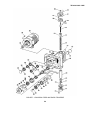
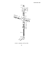
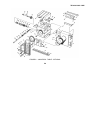
1
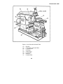
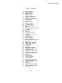
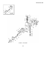
TM 9-3418-201-14&P
TECHNICAL MANUAL
OPERATOR’S, ORGANIZATIONAL, DIRECT
SUPPORT, AND GENERAL SUPPORT MAINTENANCE
MANUAL INCLUDING REPAIR PARTS LIST
FOR
SHAPER, METAL CUTTING
HORIZONTAL
NSN 3418-00-808-0475
(ROCKFORD MACHINE TOOL CO.)
HEADQUARTERS, DEPARTMENT OF THE ARMY
JULY 1981
TM 9-3418-201- 141&P
WARNING
Dirt or dirty oil in this machine will cause serious injury and expensive repairs. Use only
clean vessels for handling oil, and pour all oil through strainer provided.
WARNING
Oil level must be maintained. Entire system should be drained and refilled with fresh oil
often enough to maintain the lubricating value of the oil. All oils should have anti-rust
and oxidation additives.
WARNING
Before breaking any circuit connections, be certain the electrical power is off and the
system is relieved of trapped pressure.
TM 9-3418-201-14&P
Technical Manual
No. 9-3418-201-14&P
}
HEADQUARTERS
DEPARTMENT OF THE ARMY
Washington, DC, 17 July 1981
OPERATOR, ORGANIZATIONAL, DIRECT SUPPORT
AND GENERAL SUPPORT MAINTENANCE MANUAL
INCLUDING REPAIR PARTS LIST
FOR
SHAPER, METAL CUTTING, HORIZONTAL
(NSN 3418-00-808-0475)
REPORTING OF ERRORS
You can help improve this manual. If you find any mistakes or if you know of a way to
improve the procedures, please let us know. Mail your letter, DA Form 2028
(Recommended Changes to Publications and Blank Forms), or DA Form 2028-2, located
in the back of this manual direct to: Commander, US Army Armament Materiel Readiness
Command, ATTN: DRSAR-MAS, Rock Island, IL 61299. A reply will be furnished direct
to you.
Manufactured by:
Rockford Machine Tool Co.
2500 Kishwaukee Street
Rockford, IL 61101
Procured under Contract No. DAAA09-76-C-6910
This technical manual is an authentication of the manufacturers’ commercial literature
and does not conform with the format and content specified in AR 310-3, Military
Publications. This technical manual does, however, contain available information that is
essential to the operation and maintenance of the equipment.
i
TM 9-3418-201-14&P
TABLE OF CONTENTS
Page
Receiving and Handling......................................................................................................................
Cleaning .............................................................................................................................................
Installation ..........................................................................................................................................
Floor Plan ...........................................................................................................................................
Electrical Connections and Wiring......................................................................................................
Hydraulic Oils .....................................................................................................................................
Wiring Diagram ..................................................................................................................................
Filling Oil Reservoir. ...........................................................................................................................
Starting the Machine...........................................................................................................................
Operating the Machine. ......................................................................................................................
Universal Table...................................................................................................................................
Power Feed. .......................................................................................................................................
Cutting Tools.. ....................................................................................................................................
Hydraulic Circuit. ................................................................................................................................
Reversing Valve Chokes.. ..................................................................................................................
Motor and Pump. ................................................................................................................................
Pump Maintenance Instructions . .......................................................................................................
Pump Service Parts Information ........................................................................................................
Flow Control and Overload Relief Valves ..........................................................................................
Valve Maintenance.............................................................................................................................
Valve Parts Drawing...........................................................................................................................
Specifications. ....................................................................................................................................
Maintenance - Lubrication. .................................................................................................................
Lubrication Chart. ...............................................................................................................................
Parts List.............................................................................................................................................
1
2
2
3
4
4
5
6
6
8, 9
10
11
11
12, 13
14, 15
15
16-23
24-29
30
31, 32
33-36
37
38
39
40- 65
LIST OF ILLUSTRATIONS
Figure Title
1
2
3
4
5
6
7
8
9
10
11
12
13
14
Page
Right Side with Plain Table....................................................................................................
Left Side with Universal Table...............................................................................................
Tool Head..............................................................................................................................
Power Downfeed - Optional...................................................................................................
Main Crossrail Unit.. ..............................................................................................................
Crossrail Gear Box. ...............................................................................................................
Crossrail Feed and Rapid Traverse. .....................................................................................
Crossrail Vertical Feed.. ........................................................................................................
Universal Table - Optional.....................................................................................................
Pilot Valve and Trip Dogs......................................................................................................
Combination Valve and Controls...........................................................................................
Hydraulic Valves....................................................................................................................
Ram Cylinder.........................................................................................................................
Safety Crank..........................................................................................................................
ii
41
42
44
46
48
50
52
54
56
58
60
62
64
65
TM 9-3418-201-14 & P
INSTRUCTIONS FOR REQUISITIONING PARTS
NOT IDENTIFIED BY NSN
When requisitioning parts not identified by National Stock Number, it is mandatory that the following information be
furnished the supply officer.
1 - Manufacturer’s Federal Supply Code Number - 51292
2 - Manufacturer’s Part Number exactly as listed herein.
3 - Nomenclature exactly as listed herein, including dimensions, if necessary.
4 - Manufacturer’s Model Number - Model
5 - Manufacturer’s Serial Number (End Item)
6 - Any other information such as Type, Frame Number, and Electrical Characteristics, if applicable.
7 - If DD Form 1348 is used, fill in all blocks except 4, 5, 6, and Remarks field in accordance with AR 725-50.
Complete Form as Follows:
(a) In blocks 4, 5, 6, list manufacturer’s Federal Supply Code Number - 51292
manufacturer’s Part Number for the repair part.
(b) Complete Remarks field as follows:
Noun:
(nomenclature of repair part)
For:
NSN: 3418-00-808-0475
Manufacturer:
Rockford Machine Tool Co.
Model:
Serial: (of end item)
Any other pertinent information such as Frame Number, Type, Dimensions, etc.
iii
followed by a colon and
TM 9-3418-201-14 & P
SERVICE MANUAL
for the
INSTALLATION OPERATION
and
MAINTENANCE
of the
HORIZONTAL, METAL CUTTING
Hy- Draulic SHAPER
16 inch
Series 15
TM 9-3418-201-14 & P
RECEIVING
Before accepting the machine
,a preliminary examination should be made
for any possible damage in transit. If there is evidence of such damage a notation to that effect should be made
on the receipt and the machine received subject to thorough inspection. When the extent of the damage has been
determined, your reports should be filed.
HANDLING
The best method of handling the shaper is by means of a crane with adequate capacity. By removing the top
boards of the crate and the water proof covering, a rope or sling may be attached as shown. The sling should be
crossed over the crane hook to prevent slipping. A sling to carry a load of at least 10,000 pounds should be used.
If no crane is available rollers must be used. In moving the machine on rollers leave the skids attached until it has
reached the place of installation. Always be careful that the ends of the skids do not drop off a roller as damage to
the machine may result.
1
TM 9-3418-201-14 & P
CLEANING
Before shipment, all unpainted surfaces were coated with a rust preventive compound. This may be removed by
wiping with rags saturated with a nonflammable cleaning fluid. Clean only by wiping and brushing. Do not use
compressed air as this tends only to force dirt and grit into the working parts.
After the slushing compound has been removed, wipe all finished surfaces with a cloth moistened with lubricating
oil. Do not move any of the controls or moving parts until the machine has been thoroughly cleaned and lubricated.
INSTALLATION
The first consideration in maintaining the accuracy of any machine tool is to see that it is supported by a rigid
foundation. For a machine of this size a concrete floor furnishes sufficient foundation. Anchor bolts should be embedded
in the concrete.
Holes for six anchor bolts are provided in the base plate, one pair near the front end, one pair at the front corner of
the column, and one pair at the rear corner. Level the machine by using steel wedges ,under the base plate near the
anchor bolts at the four corners of the column, leaving the front end of the base plate free. For crosswise leveling use the
finished top of the cross rail. For lengthwise leveling use the finished top of the column along the ram ways. Use a
precision machine level. A carpenter’s or mason’s level is not sufficiently accurate for this purpose. When the machine
has been leveled from these four points, tighten the nuts on those four anchor bolts. Then, with the leveling screws at the
front of the base plate make adjustment until the plate on which the outer table support slides is exactly parallel to the
cross rail and tighten the screws on the two front anchor bolts.
With a rich mixture of portland cement and clean building sand and enough water to make a thick mixture (grout)
fill the space between the base plate and the floor using sufficient grout around the outside to embed the base plate to a
depth of one inch or more. Allow sufficient time for the grout to harden before starting the machine. On a machine having
a plain table the entire base plate may be embedded in grout as shown.
The universal table requires clearance so that
the outer table support may be lowered to the bottom
surface of the base plate. Therefore the space across
the front end of the base plate should be filled with grout
only up to the bottom surface of the plate.
The floor plan on the following page is typical of
the area and shape of the space required. For actual
installation use only the certified print which is mailed
prior to shipment of the machine.
If a concrete foundation is to be built,
consideration should be given as to whether or not
conduit for electric wiring is to be embedded. The floor
plan shows the location of the entrance of electric wires.
2
TM 9-3418-201-14&P
3
TM 9-3418-201-14&P
ELECTRICAL CONNECTIONS AND WIRING
The electrical system of the hydraulic shapers consists of a motor for driving the main hydraulic pump, a motor to
power the table traverse and rail elevation, together with suitable push button station and magnetic switches for starting
the motors.
A wiring diagram shows the wiring which is considered standard; however, for your individual machine use only the
wiring diagram furnished for that machine.
When connecting the line wires to the control panel, jog the motors slightly to see that they run in the direction
indicated by the arrows attached to them. Remember that as yet the hydraulic system has no oil in it, therefore any more
than a slight jogging of the motor will be courting injury to the pump.
HYDRAULIC OILS
The oil used in the hydraulic system must be of a type proven suitable for the purpose. It should not foam nor
emulsify under constant agitation, should have high resistance to oxidation, and must be free from lint, chips, water,
sludge, and all other foreign substances. In addition it should meet the following specifications:
Viscosity Index ...........................73 Min.
Viscosity .....................................300 S. S. U. at 100° F.
Pour Point...................................10 F. Max.
Flash...........................................355° F. Min.
Fire .............................................405° F. Min.
4
TM 9-3418-201-14&P
5
TM 9-3418201-14 & P
FILLING OIL RESERVOIR
For filling the oil reservoir it is recommended that a 30 gallon drum of an approved oil be obtained.
The oil may be poured through the rectangular
opening in the cover plate on the left side of the machine
column. Pour in sufficient oil to bring the level up to the
mark on the gauge at the lower rear corner of the
column. This will be sufficient until after the machine has
been started. At that time more oil must be added since
a consider- able quantity will be drawn from the reservoir
to fill the pump, valves, piping and cylinder.
Use only clean new oil and clean containers for
handling it.
STARTING THE MACHINE
Before starting the machine, lubricate it thoroughly as
directed in the section LUBRICATION. When ready to
start, set the ram selector lever in the STOP position and
the table selector and clutch engaging lever in the OFF
positions. The stroke control knobs should be well
toward the ends of their slot to give the ram a long
stroke. Set the flow control lever about midway across
its dial.
Start the main driving motor by pressing the START button of the control station. Allow the motor to run idle for a
minute or two to prime the pump and build up pressure which starts the oil flowing through the overload relief valve. Shift
the ram start-stop lever to the LOW position to set the ram into motion. If at first the ram action is unsteady, it is due to the
air in the system. If allowed to run for a few minutes, the air will be worked out and the ram will have a steady motion with
smooth reversals.
After the first few strokes observe the ram ways to see that a film of oil is covering their surfaces. If the ram ways
are dry, stop the machine immediately and investigate as instructed in the section LUBRICATION.
The machine has now been prepared for operation and therefore the motor should be stopped by pressing the
STOP button and returning all control levers, to their OFF or STOP positions. When the oil has come to rest, check the
level in the oil gage and add whatever is necessary to again bring it up to the correct height. It may be one half inch above
or below the mark on the gage without danger.
6
TM 9-3418-201-14&P
7
TM 9-3418--01-14 & P
OPERATING THE MACHINE
All control levers and adjustments are grouped within a small space, making them convenient to the operator’s
reach.
Identification numbers of the various controls shown in illustration on opposite page are as follows:
1. The ball crank on the top of the vertical feed screw is for manually feeding the tool head up or down. Directly
below the crank is a graduated collar which shows the amount of travel. Each graduation of the dial represents a
movement of one thousandth (0.001)inch of the tool head.
When so ordered a power feeding mechanism is furnished for the tool head. A description of the power vertical
feed is given on page 15.
2. This knob and plunger must be pulled outward to allow lever 3 to be shifted to the high speed range position.
3. This lever starts, stops, and selects the speed of the ram. There are two ranges of speed, high and low.
Within each range lever 6 provides infinitely variable speed changes. The dial on lever 3 is marked to show the setting for
the various functions.
4. The length and position of the ram stroke is determined by the setting of these knobs. On the inside of the
ram and attached to these knobs are the reversing cams which actuate the pilot valve for reversing the ram stroke. The
knob at the rear reverses the ram at the end of the cutting stroke while the one at the front reverses on the return stroke.
5. Reversal of the direction of ram stroke at any point during either cutting or return is accomplished by means of
this lever. To become acquainted with the advantages of this lever, start the ram into motion with a long, slow stroke.
When the ram has reached a point about midway in the cutting stroke shift this lever toward the rear and note that the ram
immediately reverses. Shifting toward the front has the same effect during the return stroke.
As an example of the value of this feature, suppose that the feed had been set to an amount greater than the
power of the machine could accommodate and the ram stalled in the cut. By simply shifting this lever the tool is backed
out to permit adjustment of the difficulty. Other advantages will be discovered as experience is gained in the operation of
the machine.
6. The valve operated by this lever varies the quantity of oil delivered to the ram cylinder and thereby governs the
ram speed. The valve operates in the same manner in both the high speed and low speed ranges which are selected by
lever 3.
Shifting the lever toward the front decreases the ram speed; toward the rear increases it. By using levers 3 and 6
in conjunction with each other any speed, from the lowest in the low speed range to the highest in the high speed range,
may be obtained. When operating in the high speed range, the flow of oil to the cylinder must not be reduced below the
low speed range.
7. The amount of cross or vertical feed to the table is regulated by this handwheel. Screwing it down decreases
the feed, up, increases it. The selection as to vertical or cross feed is made by the setting of lever 8.
8 and 9.
These two levers are used in conjunction with each other. Lever 9 selects the setting for either
vertical or horizontal movement of the table and after it has been set lever 8 selects the direction of motion for that setting.
8
TM 9-3418-201-14 & P
Shifting lever 9 to the left engages the vertical travel and then lever 8 selects the upward or downward travel of the
table and cross rail. Shifting lever 8 to the left or FORWARD position raises the rail, to the right or REVERSE lowers the
rail.
If lever 9 is set to the right or CROSS position and--lever 8 to the FORWARD position the table will travel toward
the rear or away from the operator. Shifting lever 8 to the REVERSE position causes the table to move toward the
operator. These settings apply to both the feeding and power traverse mechanisms. When using the power traverse be
sure that the traverse motor is STOPPED before shifting the levers. When using the hand safety crank set both levers 9
and 8 to the OFF position.
10. This knob must be pulled up to shift lever for vertical travel of rail.
11. When the cross rail is to be raised or lowered by hand, the safety crank furnished is to be used on this shaft.
When using the hand crank lever 9 must be in the OFF position and the upper plates which clamp the cross rail to the
column must be released. The graduated collar on the shaft indicates the amount of movement of the rail. Each
graduation indicates a movement of one thousandth (0.001) inch. A setscrew in the knurled rim may be used for locking
the dial at any setting.
12. This is the screw for moving the table along the cross rail. The squared end is to receive the safety crank for
hand operation. When using the crank lever 9 must be in the OFF position. The graduated collar on the screw indicates
the amount of movement of the table. Each graduation indicates a movement of one thousandth (0.001ol) inch. A
setscrew in the knurled rim may be used to lock the dial at any setting.
The screw projects through the opposite end of the cross rail permitting the use of the crank at either end.
Directly behind the feed cylinder is an electric motor to supply power for the rapid traverse of the table either
vertically or horizontally. The motor is started and stopped by using the TRAVERSE button on the control station. The
motor will run only as long as the button is held in contact.
The direction of both feed and traverse is determined by the setting of levers 8 and 9.
13. Before lowering the table be sure to loosen the clamp nuts on the outboard support, and the two clamp nuts
behind the rail. After the table has been moved to the desired position these nuts should be tightened in order to provide a
rigid support for the table during the planing operation.
14. At the rear of the cross rail and holding it to the column are four plates, two on either side. The lower plates
are scraped to a sliding fit and need no attention during the operation of the machine.
The top plates are so made that the rail may be clamped to the column by tightening the nuts which hold the plates
in position. When raising or lowering the rail the clamp plates nust be loosened.
When shaping is to be done with the rail in a stationary position the clamp plates should be tightened to provide
greater rigidity to the work table.
9
TM 9-3418-201-14 & P.
UNIVERSAL TABLE
The hydraulic shaper is furnished with a plain table as standard equipment, however, a universal table is available
as alternate equipment when so ordered.
The universal table has a tilting top which is adjustable 15 degrees in either direction. To tilt the top loosen the
clamping nuts(l4)on both sides of the table. Unscrew and remove locating block(18);then, with the hand crank on worm
shaft(19),tilt the table to the desired position reading the angle on etched plate (22). Tighten clamping nuts (l4)before
doing any cutting.
The table also revolves on its trunnion through a complete revolution of 360 degrees. To revolve the table loosen
clamp nuts(15)and unscrew and remove tapered dowel pin (21). With a crank on worm shaft(16 or 20)the table may be
rotated to the desired angle which is read on the graduations at (l17).Tighten clamp nuts (15)before doing any cutting.
When the table is returned to the upright position dowel pin(21) may be replaced thereby assuring the exact
positioning of the table.
If the table is rotated 90 degrees to the left it will present a large flat working surface with T slots similar to a plain
table.
When raising or lowering the table do not forget to loosen the clamp nuts on the outboard table support.
10
TM 9-3418-201-14 & P
TOOL HEAD POWER FEED
The attachment providing power vertical feed to the tool head is not standard equipment but is applied to
machines when so ordered.
The attachment consists of an adjustable cam or shoe attached to the column, and an arm and roller riding over
the cam, and connected to the vertical feed screw of the tool head
The direction of feed, up or down, is selected by
a lever mounted on the top of the ram.
The amount of feed is regulated by a screw with
a knurled knob mounted on the side of the ram. Turning
the screw downward decreases the amount of feed;
upward increases it. The amount of feed is indicated by
the graduated collar at the top of the vertical feed screw.
The actuating cam on the top of the column is
adjustable forward and backward and should be set so
that the feeding action takes place just before the end of
the return stroke of the ram.
CUTTING TOOLS
The conventional types of cutting tools are suitable for use on this machine.
Plain forged tools may be used or the inserted bit type of tool holder sets may be obtained from any of several
manufacturers of such articles.
If formed tools are to be used they, of course, must be made to suit the job in hand.
11
TM 9-3418-201-14 & P
HYDRAULIC CIRCUIT
The diagram below shows the general principle on which the circuit operates. It does not show the details of
piping on the machine.
Before shipment of the machine adjustments were made to assure the correct functioning of all parts. Further
adjustments should be unnecessary and may be detrimental to the smooth operation of the machine,
Illustrations on the following pages show the actual piping of the circuit.
12
TM 9-3418-201-14&P
13
TM 9-3418-201-14&P
REVERSING VALVE CHOKES
On the main valve body are placed four choke plugs, two at each end, for the purpose of adjusting the ram
reversals at each end of its stroke. By means of these chokes the rate of deceleration at the end of the stroke may be
controlled. Likewise the rate of acceleration at the beginning of the stroke may be controlled.
These chokes are adjusted by experts at our factory to give the most suitable ram action under the conditions
existing here. No further adjustment should be necessary and the chokes should not be tampered with.
However, in rare cases, the conditions under which the machine must operate in a customer’s plant may require a
slight readjustment of the chokes. If such a case arises no one except a thoroughly experienced mechanic should attempt
to change the setting.
The following is offered in explanation of the functioning of the choke plugs.
They operate on the principle of a needle valve for governing the rate at which oil may be discharged from the
space at the ends of the reversing valve spool, and therefore the speed at which the valve spool travels during the shifting
action. If the chokes are open too far the ram will reverse with a shock or bump at the end of the stroke; if closed too
much the ram will be sluggish in its action.
Chokes 3 and 4 control the reversal of the ram at the end of the cutting stroke and beginning of the return stroke.
Chokes 1 and 2 control the reversal at the end of the reverse stroke and beginning of the cutting stroke. When the correct
adjustment has been made the ram will have a snappy action but still without shock.
14
TM 9-3418-201-14&P
It was stated previously that no one except a thoroughly experienced mechanic should be allowed to make
adjustments. This is for the reason that no exact formula can be given for setting the chokes. It is more a matter of
gaining experience in the results obtained with different settings. However, it can be explained that screwing the chokes
inward will slow up the ram action, while opening them will produce sharper reversals. Adjustments should be made
slowly and carefully so that the result of each slight turn may be observed.
Care must be taken to see that chokes 2 and 3 are not screwed in too far as this would cause damage to the valve
spool and the choke.
The chokes become accessible by removing the square door from the left side of the column.
Before starting to make adjustments the feed cylinder should be entirely closed off either by closing the valve at
the bottom of the cylinder or by screwing the feed adjusting screw down so that the feed piston has no movement.
For the first adjustment of the chokes the ram should be set for the shortest possible stroke and adjustments
made for the low and high ram speeds. Then set the reversing dogs for a long ram stroke and observe that it may be
necessary to open the chokes slightly to get the best action. The ideal setting is to strike a balance between the short
stroke at high speed and the long stroke at low speed.
MOTOR AND PUMP
The Hy-Draulic shaper is powered by an electric motor directly connected to the hydraulic pump by a flexible type
.
coupling. On the 16”, 20” and 24” standard a 71/2 H. P motor is used. The 24” Heavy and 28” carry a 10 H. P. motor.
On direct current or 60 cycle alternating current the motor runs at 1200 R.P.M., on 50 cycle at 1000 R.P.M., and
on 25 cycle at 750 R.P.M.
On the 16', 20' and 24' standard the pumps are as follows:
1200 R. P. M. ...........................................................................Model V-135-20
1000 R. P. M. .............................................................................. .”
V-135-U-20
750 R. P. M. .................................................................................." V-135-X-20
On the 24' Heavy and 28' the following pumps are used:
1200 R. P. M. ...........................................................................Model V-135-X-20
1000 R, P. M. ................................................................................" V-145-20
750 R. P. M.. ................................................................................." V-145-20
Installation and maintenance information on all pumps is given in
Bulletin 1-133744 and I-3100S.
Parts are listed on parts drawing I-3102S. Both of these publications are included in this book.
Sequence valve pressure is set at 250 lbs. with pump running and ram stopped.
Main pressure is set at 1000 lbs. with ram stalled in cut or at the end of stroke.
15
TM 9-3418-201-14&P
SERVICE
AND
MAINTENANCE INSTRUCTIONS
SINGLE STAGE
SINGLE AND DOUBLE
VANE PUMPS
OPERATING CHARACTERISTICS
TYPE ..................................Balanced Vane, Fixed Delivery
SERIES .................................Single and Double, Single Stage
OPERATING PRESSURE. ...... See Performance Data
INPUT SPEED, RPM................ See Performance Data
OPERATING FLUID ..... 150 S.S. U. at 100°F
MOUNTNG ...........Face, Foot, Flange, Electric
Motor End Bell
CONNECTIONS ...... Pipe Thread Body Ports or Flanges
Performance data is based on input speed at 1200 rpm , pumping
petroleum base fluid at 1200 F. Minimum recommended drive speed for
all series is 600 rpm,. Characteristics at other drive speeds are
approximately proportional to rpm . For performance data when using!
other than petroleum base fluids, see applicable Installation drawing ,
shown on page 25.
16
TM 9-3418-201-14&P
DOUBLE PUMP SERIES - SINGLE STAGE
Small Series Combination
17
TM 9-3418-201-14&P
Large and Small Series Combination
DESCRIPTION
This manual contains service and maintenance
information for single and double pumps.
These
hydraulically balanced cartridge type vane pumps are
used to provide a constant supply of hydraulic fluid under
pressure and are produced in three basic housing sizes:
small, intermediate and large. Cartridges of different
displacement may be used interchangeably in each
series. These pumps can be used as single units or two
maybe assembled on a common drive shaft (double
pump) providing an almost infinite number of
combinations. Figure 1 illustrates a cross sectional view
of a flange mounting, small and intermediate series
combination double pump, assembled for LH rotation.
Figure 1
18
TM 9-3418-201-14&P
OPERATION
Operation: Pumping is performed by cartridges
good quality, high temperature, bearing grease.
consisting of a ring,’ rotor, two bushings, twelve vanes
CAUTION
and a locating pin or screws (see figure 2). The splined
Over-lubrication can damage the shaft seal.
pump shaft rotates driving a slotted rotor. Vanes within
the rotor slots are thrown out by centrifugal force and
Routine Inspection and Maintenance:
held out by system pressure to follow a double lobed
cam ring. Movement of the vanes in and out as they
a.
Make certain all hydraulic connections are tight
follow the cam causes the chambers between them to
to prevent fluid leakage or entry of air into the system.
increase in size and pick up fluid from the reservoir as
the vanes cross the inlet porting.
Chamber size
b.
Check fluid level in the reservoir to assure an
decreases when the vanes cross the outlet porting
adequate supply to the pump intake. When adding fluid,
forcing fluid out into the system.
always pour it through a 200 mesh or finer screen.
The size of the cartridge ring determines the pump
displacement. Ring change alters delivery. However,
the 11 gpm ring in the small series and the 36 gpm ring
in the intermediate series are used with wide vanes and
rotor so conversions
to these capacities require
additional change of rotor, vanes and head.
c.
Inspect the filter element and replace if dirty.
d.
Inspect the fluid for contamination.
If
contaminated, drain the system and thoroughly clean the
reservoir. Change the filters and flush the complete
system with clean fluid. Again drain the system and refill
with new fluid.
Lubrication: None is required for current design models.
Older designs require lubrication of the front shaft
e.
Check the reservoir air breather and replace if
bearing. A grease fitting is provided on top the pump
dirty.
body. (Some of the larger pumps also incorporate a
grease relief fitting on the bottom of the body.) It is
recommended that these fittings be lubricated sparingly
(approximately one tablespoonful every six months) with
a low pressure gun using a
OVERHAUL
Complete overhaul may be accomplished by means of
Remove light scores by lapping; replace if heavily
cartridge and gasket kits.
scored. Stone new parts lightly to remove burrs.
d.
Bearings for cracked or pitted races or pitted
Disassembly may be accomplished in the order shown
balls. Replace if defective.
in the illustration (see figure 3 or 4).
e.
Shaft for wear at seal lip journal. Replace if
WARNING
scored.
Before breaking any circuit connections,
f.
Replace shaft seal, 0 ring and head packing at
be certain the electrical power is off and
each teardown.
the system is relieved of trapped
pressure.
Reassembly: Assemble parts in reverse order of
Prepare a clean, lint-free surface on which to lay internal
disassembly, noting the following:
parts of the pump. Thoroughly clean areas adjacent to
a.
Assemble seals with spring toward inside of the
the components being removed to minimize possibility of
pump.
dirt entering the system. Cap or cover all exposed ports
b.
Coat all parts with compatible fluid and lightly
and openings into the system.
lubricate the lip of the shaft seal to prevent damage
during installation.
Inspect and replace as follows:
c.
Install bearing and snap ring on shaft end and
place in the body.
a.
Vanes, for wear and sticking in rotor slots.
d.
Spring in the shaft seal must be toward the shaft
Vanes must move in slots from their own weight when
bearing.
dry. Replace if defective. Stone new vanes lightly on an
e.
Install cartridge parts so arrows on the parts are
India stone to remove sharp edges.
pointed for intended rotation as viewed from the shaft
b.
Ring, for scored or cross-grooved cam face.
end.
Replace if grooved or scored.
f.
Assemble the pin so its small diameter end fits
into the body for RH rotation (large end in body for LH
Faces of rotor and bushings for wear and scoring.
rotation). See installation page 23.
19
TM 9-3418-201-14&P
Figure 2
CARTRIDGE ASSEMBLY AND INSTALLATION
Figure 2 illustrates a typical cartridge assembly and
HEAD SCREW ADJUSTMENT
installation, when viewed from the head end. The
cartridge assembly procedure is the same for both single
Some pump cover heads and intermediate heads
and double pumps, depending on the direction of shaft
(double pumps) are provided with two small holes to
rotation.
match the two diameters of the locating pin. Install the
head so the pin fits the hole size to prevent the pin from
The stepped diameter locating pin prevents improper
bending or shearing when the pump is put into operation.
assembly of the cartridge. However, caution must be
exercised to install the cartridge properly for the direction
Pull the head down gradually, alternately tightening the
of rotation desired.
screws 1800 from each other until the head seats evenly
on the bushing. Turn the shaft by hand during the
process until a light, smooth snugness is felt through a
The large series pump cartridges have a locating screw
complete revolution. Do not over-tighten the screws,
and a retaining screw in lieu of the locating pin used in
causing the shaft to bind.
the small and intermediate series.
Before starting these pumps, check for freedom of
movement of the internal parts by turning the shaft by
hand. Never start a pump which shows evidence of
binding.
NOTE
The direction of rotation (RH or LH) is
always determined by viewing the pump
from the shaft end.
CAUTION
A new or overhauled pump must be started
under load on the first run. This will create
a back pressure to assure adequate
internal lubrication. After a pump is broken
in, it can be started under
no-load
conditions.
INSTALLATION
Right hand rotation: Insert the small end of the locating
pin into the small hole in the pump body at a 3
o’ clock position.
Left hand rotation: Insert the large end of the locating
pin into the large hole in the pump body at a 6
o’clock position.
Start the pump by jogging the drive motor a few times to
be sure the pump is primed.
20
TM 9-3418-201-14&P
If the pump is new or has been overhauled, be certain it
loading of’ the drive shaft.
is properly installed. Check the direction of shaft rotation
Pump life will be shortened by operation beyond
and alignment of the shaft with the drive motor. Since it
maximum pressure and speed ratings. Since these units
is difficult to achieve perfect shaft alignment, a flexible
are positive displacement, a relief valve must be used to
coupling must be used.
limit maximum system pressure to recommended limits.
Exercise care with pumps driven by belts, chain drives,
spur gears, etc. to prevent excessive side
TROUBLESHOOTING CHART
TROUBLE
PROBABLE CAUSE
REMEDY
PUMP NOT DELIVERING FLUID
Pump driven in wrong direction of
Must be reversed immediately to
rotation.
prevent seizure. Check direction
of drive rotation against proper
pump rotation as indicated by arrow
on body.
Pump drive shaft broken or shaft
Remove pump from accessory
key sheared (direct drive).
mounting pad and determine damage to pump cartridge. Replace
needed parts.
Fluid intake pipe in reservoir
Drain complete system. Add new
blocked or oil viscosity too heavy
fluid of proper viscosity. Filter
to pick up prime. Viscosity should
the new fluid as recommended.
not exceed 4000 S. S.U.
Checkall filters for dirt and sludge.
Air leaks at intake.
Check intake connection for air
leak. Tighten securely.
Pump not priming.
Loosen connection in outlet line.
Bleed-off air until fluid flows.
Oil level too low.
The fluid level must be above intake opening in intake pipe. Check
minimum drive speed which may be
too slow to prime the pumps.
Vane or vanes stuck in rotor
Inspect rotor slots for wedged chips
slots.
or foreign particles and replace all
damaged parts. F 1 u s h complete
system thoroughly by recommended
processes and fill system with new,
clean hydraulic fluid.
PUMP MAKING NOISE
Partially clogged intake strainer
Pump must receive intake fluid freely
or restricted intake pipe.
or cavitation will result.
Drain system, clean intake pipe,
and clean or replace strainer. Add
new fluid and strain by recommended
procedures.
Defective bearing.
Disassemble pump and replace
bearing.
Air leak at pump intake piping
Test by pouring oil on joints and
joints or pump shaft seal.
around drive shaft. Listen for
change in operation. Tighten joints
affected. Check pump shaft oil seal
for leakage and replace if necessary,
in accordance with instructions outlined in this manual. Check’ shaft
for scoring at seal contact area and
replace shaft if grooving is evident.
Coupling misalignment.
21
Check shaft bearing and seal for
possible damage. Replace if
necessary. Re-align shafts.
TM 9-3418-201-14&P
reducing wear and excessive noise due to cavitation.
Thus permitting heavier viscosity fluids to be used while
improving overall pumps performance.
The intermediate series, current design, cartridge parts
are shown in the lower inset view. These modified parts
provide better inlet conditions by
1.
2.
3.
4.
5.
6.
7.
8.
HEAD SCREW
HEAD
HEAD GASKET
HEAD BEARING
CARTRIDGE (Includes items 6 thru 11)
BUSHING
PIN - Locating
RING
9.
10.
11.
12.
13.
14.
15.
16.
Figure 3
VANE
ROTOR
BUSHING
SHAFT KEY
BRACKET SCREW
BRACKET (Foot/Flange)
FLANGE CASKET
DRIVE SHAFT
REFERENCE DRAWINGS
22
17.
18.
19.
20.
21.
22.
SNAP RING
SHAFT BEARING
SHAFT SEAL
SPACER
0 RING (Spacer)
BODY
TM 9-3418-201-14&P
Figure 4
1. HEAD SCREW
2 HEAD
3 HEAD GASKET
4 CARTRIDGE
(Includes Items 5 thru 10)
5 BUSHING
6 PIN - Locating
7 VANE
8 ROTOR
9 RING
10 BUSHING
11 SCREW
12 LOCKWASHER
13 GASKET
14 SCREW
15 LOCKWASHER
16 MOUNTING FLANGE
17 GASKET
18
BODY
*19
FLANGE SCREW
*20
FLANGE (Inlet)
*21
GASKET (Inlet)
*22
FLANGE SCREW
*23
FLANGE (Outlet)
*24
GASKET (Outlet)
25
HEAD SCREW
26
LOCKWASHER
27
HEAD (Intermediate)
28
GASKET
29
NUT
30
LOCKWASHER
31
BEARING
32
CARTRIDGE
(Includes items 33 thru 39)
33
LOCATING SCREW
34
RETAINING SCREW
35 BUSHING
36 VANE
37 ROTOR
38 RING
39 BUSHING
40 SHAFT KEY
41 BRACKET SCREW
42 BRACKET
(Foot/Flange)
43 LOCKWASHER
44 FLANGE GASKET
45 RETAINER SCREW
46 RETAINER
47 RETAINER GASKET
48 DRIVE SHAFT
49 LOCK NUT
50 LOCKWASHER
51 BEARING
23
52 SHAFT SEAL
53 SEAL
(Used on basic design only)
54 FLANGE SCREW
55 FLANGE (Inlet)
56 GASKET (Inlet)
57 FLANGE SCREW
58 FLANGE (Outlet)
59 GASKET (Outlet)
60 PLUG
61 GREASE FITTING
(Used on basic design only)
62 GREASE RELIEF FITTING
(Used on basic design only)
63 SCREW
64 ROTATION PLATE
65 SCREW
66 NAME PLATE
TM 9-3418-201-14&P
SERVICE
PARTS
INFORMATION
Intermediate Size
V-124, V-134, V-144 Series
Basic, -10 & -20 Designs
24
TM 9-3418-201-14&P
25
TM 9-3418-201-14&P
26
TM 9-3418-201-14&P
27
TM 9-3418-201-14&P
To insure sustained efficiency and maximum trouble-free life of this precision equipment, initial and continuous filtration of
the fluid medium to 25 microns or less is essential. (For information pertaining to 10 micron filters, see installation drawing
I & M 229847.)
28
TM 9-3418-201-14&P
ROTATION
RIGHT HAND ROTATION VIEWED FROM DRIVESHAFT
END IS STANDARD LEFT HAND ROTATION MAY BE
SPECIFIED BY ADDING SUFFIX "LH" TO MODEL NUMBER
EXAMPLE V 134X 20 LH
INLET AND OUTLET PORTS REMAIN AS SHOWN
REGARDLESS OF DIRECTION OF SHAFT ROTATION
CHANGE OF INTERNAL ASSEMBLY, IS NECESSARY
WHEN CHANGE OF DRIVESHAFT ROTATION IS
REQUIRED
FLUIDS PERMISSIBLE
PETROLEUM OIL WITH A VISCOSITY RANGING BETWEEN
150 AND 225 SSU AT 100 F IS RECOMMENDED
FIRE RESISTANT FLUIDS
CAUTION SYNTHETIC AND WATER GLYCOL TYPE FIRE
RESISTANT FLUIDS MAY BE USED, BUT THEY HAVE HIGH
SPECIFIC GRAVITIES WHICH LIMIT THE GPM POSSIBLE
THROUGH ANY ONE PUMP HOUSING EXCEEDING THIS
LIMYT WILL PRODUCE CAVITATION WITH RESULTANT
WEAR AND NOISE .SEE BULLETIN 59 731 DRIVE SPEED
LIMITED TO 1200 RPM SELECT GPM FROM CHART ON
REVERSE SIDE
SYNTHIETIC FLUIDS PHOSPHATE ESTERS
PHOSPHATE ESTER BASE AND CHLORINATED
HYDROCARBON FLUIDS AS PRODUCED BY
RESPONSIBLE SOURCES FOR RATINGS GIVEN
HEREIN ARE RECOMMENDED SELECT FLUIDS
WITH A VISCOSITY AS CLOSE AS POSSIBLE T0
THAT FOR PETROLEUM OIL DESCRIBED ABOVE
SPECIFIC GRAVITY MUST NOT EXCEED I 42
PUMPS FOR USE WITH SYNTHETIC FLUIDS
REQUIRE SEALS MADE OF DIFFERENT MATERIAL
TO OBTIAN PUMPS EQUIPPED WITH SPECIAL
SEALS ADD PREFIX F1 TO MODEL NUMBER FOR
PHOSPHATE ESTER AND PHOSPHATE ESTER
BASE
FLUIDS
F3
FOR
CILORINATED
HYDROCARBON FLUIDS
HERE IN. ARE RECOMMENDED SELECT FLUIDS
WITH A VISCOSlTY AS CLOSE AS POSSIBLE TO
THAT FOR PETROLEUM OIL DESCRIBED ABOVE
IT IS RECOMMENDED THAT TEMPERATURES
FOR WATER GLYCOI S EE LIMITED TO A
MAXIMUM OF 140 F., CONSISTENT WITH THE
VISCOSITY RECOMMENDATIONS
WATER OIL EMULSIONS GENERALLY SHOULD
NOT BE USED WITH THESE PUMPS TO OBTAIN
SATISFACTORY SERVICE WITH EMULSIONS.
USE 521 4 T YPE PUMPS SHOWN ON
INSTALLATION DRAWINGS I 2366594 ANO
236695
MAXIMUM SPEED RATINGS ARE GIVEN FOR THREE
TYPES OF FLUIDS SPEEDS ARE INFLUENCED BY
SPECIFIC GRAVITY, VISCOSITY AND SUCTION HEAD
PUMP SUCTION AND SPEED SHOULD BE RELATED SO
T1IAT VACUUM AT PUMP INLET DOES NOT EXCEED S" OF
MERCURY FOR PETRO LEUM OIL, 3" FOR SYNTHETIC
FLUID AND S" FOR WATER GLYCOL TYPE FLUIDS
FILTRATION
FOR MAXIMUM OVER ALL EFFICIENCY AND SERVICE
LIFE, FILTRATION OF 25 MICRON OR LESS IS
RECOMMENDED FOR FIRE RESISTANT FLUIDS THIS
FILTRATION IS MANDATORY
POSITION OF INLET AND OUTLET CONNECTIONS MAY BE
REVERSED BY ROTATING PUMP BODY 180 IN FOOT
MOUNTING
MAXIMUM RECOMMENDED OPERATING PRESSURE
SEE CHART
MAXIMUM RECOMMENDED DRIVE SPEED (APPROX I
SEE CHART
MINIMUM RECOMWENDED DRIVE SPEED .05 RPM
WEIGHT (APPROX)
FLANGE MOUNTED MODELS .................... 50 LBS
FOOT MOUNTED MODELS.......................... 52 LBS
NOTE PERFORMANCE DATA SHOWN ALSO APPLIES TO
THE "VK" SERIES PUMPS AS FURNISHED
ON MOTORPUMPS
EXAMPLE F1V 134X 20
WATER GLYCOLS AS PRODUCED BY RE
SPONSIBLE SOURCES, FOR RATINGS GIVEN
29
TM 9-3418-201-14P
FLOW CONTROL AND OVERLOAD RELIEF VALVE
On the 16". 20" and 24" special model FRG-06-24-11 has flow control and overload relief valves.
On the 24" Heavy and 28" the valve is
Model FRG-06-32-l1.
Maintenance information on both valves is given in
bulletin 1000-SA.
Parts for both valves are shown on parts drawing I-3402-S and 514100-1.
On all the above shapers the relief valve is set to maintain a pressure of 1000 pounds per square inch. If for any
reason there is indication that the pressure has dropped below this point it may be tested by attaching a hydraulic pressure
gage to the opening in the valve body as shown on the illustration in section HYDRAULIC CIRCUIT. Use a gauge having
at least 1500 pounds capacity.
Run the tool head carefully up against the vise or a block bolted to the table thereby stalling the ram and allowing
the pressure to build up to the maximum setting of the valve. If the gauge does not register at least 1000 pounds it is
probable that some obstruction is holding the relief valve open. To correct the difficulty proceed as instructed in bulletin
1000-SA.
PRESSURE BALANCING VALVE
The pressure balancing valve is
Model VS-22-A.
Parts are shown on Parts Drawing Figure 12.
PRESSURE LUBRICATING VALVE
The valve for maintaining pressure for the ram lubrication is a
Vertical Check Valve.
The same valve is used on all shapers described in this book.
30
No. 24-1/2
TM 9-3418-201-14&P
MAINTENANCE INFORMATION
FOR
SERIES FRG-02, FRG-03, FRG-06 & FRG-IO
FLOW CONTROL & OVERLOAD RELIEF VALVES
(REFER TO DESCRIPTIVE BULLETIN 48-36 & PARTS DRAWING 925-S)
1. MODEL NUMBERS.
This maintenance information is for flow control valves with Integral Overload Relief Valve. The complete model
number, which includes pressure range, volume control range and any special feature designation, is stamped on each
valve and should be carefully referred to when using parts drawing or when ordering service parts.
2. FUNCTION.
The primary function of these valves is to provide accurate volume control in hydraulic circuits regardless of any
variation in the imposed fluid pressure. n integral overload relief valve is also provided to limit hydraulic pressure in the
system to a predetermined maximum. Both the maximum pressure and the flow control rate are adjustable. Oil from the
system is discharged from the return connection of the valve to the tank whenever pressure builds up to the setting for
which the valve is adjusted. That portion of the volume which is not admitted to the hydraulic circuit is also returned to the
tank.
These valves may also be used for an additional purpose in the control circuit. By using the 1/4" pipe thread vent
connection, which is normally plugged and a suitable venting control circuit it is possible to remotely or automatically drop
the system pressure to approximately zero when desired. This venting arrangement is often used for automatically
dropping pressure between working cycles of a machine. The term venting is used because of the fact that pressure on
one side of the otherwise balanced control piston within the valve is dropped by connecting this chamber to tank
(atmospheric pressure through small piping connections and a control valve that, when opened, allows a small volume of
oil to flow or vent continuously into the tank. This, in turn, causes the relief valve to open wide and allow the entire pump
delivery to discharge back to the reservoir at very low pressure until the venting circuit is closed.
3. INSTALLATION.
Complete installation and operating data is given on installation drawings R-108300 for FRG-02 Series and R105340 for FRG-03, 06 and 10 Series. Bulletin 48-36 also contains information on installation and operation procedures.
Be certain that the piping from the valve return connection discharges oil to the tank below the surface of the oil in the
tank. This will do a great deal toward preventing aeration and foaming.
4. VOLUME AND PRESSURE ADJUSTMENT.
The indicating dial on the front of the valve provides a convenient means of adjusting the flow rate. Clockwise
rotation increases the flow rate. Counter-clockwise rotation decreases the flow rate. The dial may be locked in any
position by tightening the socket head locking screw located on the face of the dial.
Adjusting screw (95932) provides a convenient means of regulating the maximum system pressure within the
range of the relief valve portion of this valve. The jam nut (707691 must be loosened before turning the pressure
adjusting screw (95932). Clockwise rotation of the latter increases pressure while counter-clockwise rotation decreases
pressure.
On all applications the pressure relief valve should be set for the minimum possible system operating pressure
required to perform the necessary service. If it is set for excessive pressure, more power will be used than is necessary
whenever the valve is being held open, as for example when a piston reaches the end of its travel and stops due to some
mechanical interference.
5. CAUSES OF IMPROPER OPERATION.
Fluctuating pressure or loss of pressure at the relief valve indicates the oil has become aerated or the oil contains
foreign matter. Very small chips or filings left in the tubing or piping, wiping cloth lint, core sand, or any such foreign
substances can cause trouble. Every possible precaution should be taken to prevent any grit or dirt from entering the
system when piping the machine and filling the tank with oil. Also precautions should be taken to protect the tank air vent
opening so that the breathing action in the tank does not draw in dirt or coolant. Abrasive matter will cause pump wear
and will prevent the proper operation of control valves. Dirt cannot get in if these precautions are taken.
Small air bubbles often cause a milky appearance of the oil, and this air will usually cause noisy pump and relief
valve operation, as well as prevent the valve from holding a pressure steadily. Check to make certain that all system
return pipes (including drain connections discharging oil to the tank are well below the oil surface level: also, that no air
leaks are present in the pump intake line (refer to pump maintenance data). Both of these conditions will cause air to be
mixed with the oil. Maintain proper oil level in the tank.
31
TM 9-3418-201-14&P
6. PROCEDURE WHEN SERVICING.
The relief valve is sometimes prevented from operating correctly by lint, pipe scale or some other solid matter
lodging between the pressure control piston (82800) and its seat (962491. This results in fluctuating pressure or a
complete drop in pressure. Usually the condition can be remedied by starting the pump and then loosening the jam nut
170769] and backing off the adjusting screw (95932) counter-clockwise several turns. This relieves the pressure control
spring (96163; and often will allow the circulating oil to clean away the dirt. The relief valve adjustment should then be
turned back clockwise until the proper maximum pressure setting has been re-established. Relief valve setting may be
checked by blocking machine travel or oil circulation and testing with pressure gauge.
Should it be necessary to dismantle these valves do so by driving out the two dowel pins located either side of the
name plate. This procedure will release the plug, seal, spring and hydrostat valve from one side of the body and a plug,
seal and sleeve from the other. To remove the throttle spool remove first the small hex socket head screw releasing the
dial, then the name plate and finally the throttle. The relief valve portion of these units may be removed by turning off
acorn nut, loosening the Jam nut, turning out the adjusting screw and finally tilting the body so that the remaining portions
are allowed to drop out, After disassembly all parts should be thoroughly cleaned in an approved mineral oil solvent and
inspected for wear. Check operation of hydrostat within the sleeve. These parts are fitted to a very close tolerance,
however, the spool should have freedom of movement within the sleeve. Check the condition of the relief valve piston and
its seat. Continued operation may distort the mating faces of these parts preventing proper sealing action. if this has
happened, replace with new parts. At reassembly, replace all seals with new parts. All possible precautions should be
taken to prevent damage to the parts and to keep them clean.
7. DIAGNOSIS OF IMPROPER OPERATION.
The following chart lists the difficulties which may possibly be experienced with the flow control valves, and
indicates the probable cause and the suggested remedy. The trouble indicated in the chart may of course be due to
difficulty with other equipment in the hydraulic system. Refer also to pump maintenance data.
TROUBLE
Pressure not being
developed.
CAUSE
Relief Valve setting
not high enough.
Relief Valve sticking
open.
Relief Valve venting
Noisy or erratic
operation.
External leakage
around operating
dial or pressure
adjusting screw.
Aeration of oil due to
low oil level or
return line not discharging below oil
level.
Damaged Oil Seals.
32
REMEDY
Block machine travel or
oil circulation and test
with pressure gage.
Dirt under pressure
adjusting ball. See
Section 6 above.
Test venting circuit
(If one is used) by
blocking vent line
near valve.
All return lines must
return below oil level.
See also pump service
information.
Replace oil seal. See
Service Parts Drawings.
TM 9-3418-201-14&P
SERVICE PARTS
INFORMATION
FLOW CONTROL VALVES
Released 5-1-67
I-3402-S
33
TM 9-3418-201-14&P
34
TM 9-3418-201-14&P
35
TM 9-3418-201-14&P
36
TM 9-3418-201-14&P
37
TM 9-3418-20-14&P
MAINTENANCE
Before shipment each machine is given a serial number and is individually checked and tested by an inspector. A
record of the construction and data on the tests are kept on file. Whenever reference is made to the machine, the serial
number should be stated.
This number is stamped on the left front ram way of the column. Do not confuse this number with Model numbers
which may be found stamped on pump or valves.
Except for regular lubrication and checking the level of the hydraulic oil the machine requires little maintenance.
However, a little time spent in keeping it clean and free from dirt and chips will be well repaid by the service it will give.
Clean the machine by wiping and brushing. Do not use compressed air as it only tends to force dirt and grit into the
working parts.
Each piece used in the construction is carefully made and passes a rigid inspection before being built into the
machine. After assembly each machine is adjusted and tested by actual cutting. It therefore merits care and
consideration if it is to maintain the accuracy and long life which are built into it.
The oil in the main hydraulic system should be changed after each 2400 hours of service. After the old oil has
been removed, the oil reservoir should be carefully cleaned to insure that no sludge, metal dust, nor chips remain. The
procedure in refilling is then as explained in the paragraph FILLING OIL RESERVOIR.
After long service, wear will take place on sliding surfaces. To compensate for such wear gibs are provided which
may be adjusted or scraped to the original working clearances.
The gib for the vertical slide of the tool head has an adjusting screw at the top and at the bottom. To adjust the gib
loosen the bottom screw slightly and tighten the top one.
The gib is tapered and care must be taken to see that it is not drawn down far enough to cause it to bind. The gib
holding the ram in place has capscrews to hold it down and setscrews in the side of the column to adjust it up to the ram.
To adjust the gib loosen the capscrews and turn each of the setscrews inward slightly. Tighten the capscrews last and see
that the gib does not bind. If the gib is too tight it will cause the ram to have a jumpy motion when running at low speeds.
The gibs for holding the cross rail against the column are flat plates and when worn, must be resurfaced and
scraped to the correct fit. To hold the cross rail against sidewise motion on the column a tapered gib is placed between
the rail and column on the inside edge of the left vertical way of the column. To adjust this gib loosen the jam nut on the
lower side of the gib head and tighten the upper one.
LUBRICATION
The ways of the ram and column are lubricated under pressure from the main hydraulic system and should require
no attention. The oil passes through a filter before going to the ways. This filter can not be cleaned and therefore should
be replaced after each 1200 hours of service. The filter used is Purolator Type P-/2.
The flow of oil to the ways is regulated by two needle valves placed in the lubricating lines near the filter. Both filter
and needle valves are plainly visible when the square door is removed from the left side of the column.
Other points requiring lubrication are equipped with oil or grease fittings. Lubrication Chart A-HD-36 shows the
locations of such fittings, the type of lubricant required, and the frequency of lubrication.
38
TM 9-3418-201-14&P
39
TM 9-3418-201-14&P
MECHANICAL CONSTRUCTION
and PARTS LIST
The following drawings and photographs are presented for the purpose of acquainting the operator with the
construction of the machine, to assist in making adjustments and repairs, and to facilitate the ordering of repair parts
whenever that occasion arises.
In many cases it will save much correspondence and down time on your machine if full information is given in the
first request. Free hand sketches with the principal dimensions are very helpful.
Always refer to the machine by its serial number and give the series number of this book.
40
TM 9-3418-201-14&P
Figure 1 - Right Side with Plain Table
1
2
3
4
5
6
7
8
9
10
11
12
13
14
15
16
17
18
19
20
21
22
23
Ram Cover - Top
Ram Cover - Side
Ram Guard - Side
Ram
Ram Oil Wiper - Rear
Ram Guard Screen
Ram Guard
Shifter Ball
Shifter Lever
Volume Control Valve
Motor Bracket
Column
Base
Rail Elevating Shaft
Crossfeed Screw
R. H. End Plate
Apron - Plain Table
Table Support Slide
Table Support - Plain Table
Crossrail
Plain Table
Chip Guard - Plain Table
Ram Oil Wiper - Front
41
TM 9-3418-201-14&P
Figure 2 - Left Side with Universal Table
24
25
26
27
28
29
30
31
Rail Gib
Chip Guard - Universal Table
L. H. End Plate
Oil Gauge
Column Door
Louvre Plate
Ram Gib
Crossrail Stop
42
TM 9-3418-201-14&P
Figure 3 - Tool Head
32
33
34
35
36
37
38
39
40
41
42
43
44
45
46
47
48
49
50
51
52
53
54
55
56
57
58
59
60
61
62
63
64
65
6B
67
68
69
70
71
72
73
74
75
76
77
78
Self Locking Nut
Downfeed Handle
Distance Collar
Graduated Collar
Distance Collar Spring
Headless setscrew
Downfeed Screw Bushing
Downfeed Slide
Taper Pin
Lock Screw Pin
Slide Lock-Screw
Lock Screw Shoe
Gib Adjusting Screw
Swivel
Downfeed Nut Bracket Screw
T-Slot Bolt
Washer
Hex. Nut
Gib Adjusting Screw
Slide Gib
Downfeed Screw Collar
Woodruff Key
Downfeed Screw
Downfeed Screw Nut
Downfeed Screw Nut Bracket
Washer
Socket Head capscrew
Clapper Box Taper Pin
Clapper Box
Hex. Nut
Clamp Screw Washer
Clapper Box Clamp Screw
Clapper Box Stop
Clapper Box Return Spring
Socket Head Capscrew
Clapper Box Swivel Screw
Tool Post
Clapper Block
Tool Post Washer
Tool Post Screw
Socket Head Capscrew
Clapper Box Swivel Screw
Tool Lifter Piston
0 Ring
Swivel Screw Bearing Cap
Clapper Box Return Spring
Spring Plug
43
TM 9-3418-201-14&P
FIGURE 3 - TOOL HEAD
44
TM 9-3418-201-14&P
Figure 4 - Power Downfeed - Optional
79
80
81
82
83
84
85
86
87
88
89
90
91
92
93
94
95
96
97
98
99
100
101
102
103
104
105
108
107
108
109
110
111
112
113
Downfeed Housing Cap
Bronze Bushing
Downfeed Housing
Oil Cup
Adjusting Screw Lock Nut
Adjusting Screw
Adjusting Screw Knob
Taper Pin
Socket Head Capscrew
Feed Clutch Bushing
Miter Gear and Clutch
Elbow Oil Cup
Socket Head Capscrew
Taper Pin
Steel Ball
Socket Head Setscrew
Spring
Reverse Shaft Lever
Reverse Shaft Bearing
Reversing Shaft
Feed Clutch Lever
Taper Pin
Feed Lever Cam
Guide Washer
Socket Head Capscrew
Feed Lever Cam Guard
Socket Head Capscrew
Dowel Pin
Woodruff Key
Bevel Gear Shaft
Miter Gear Spacer
Feed Clutch
Shifter Shoe
Fitting Spacer
Tit Key
114
115
116
117
118
L19
120
121
122
123
124
125
126
127
128
129
130
131
132
133
134
135
136
137
138
139
140
141
142
143
144
’145
146
147
148
149
150
151
152
Feed Clutch Shaft
Bevel Gear
Fitting Washer
Socket Head Capscrew
Adjusting Screw Stop
Taper Pin
Socket Head Setscrew
Downfeed Screw Collar
Woodruff Key
Power Downfeed Screw
Downfeed Bevel Gear - 14 Teeth
Tit Key
Downfeed Screw Miter Bearing
Downfeed Bevel Gear Collar
Downfeed Screw Stop
Socket Head Capscrew
Socket Head Setscrew
Downfeed Nut Screw
Dowel Pin
Downfeed Bevel Gear - 20 Teeth
Taper Pin
Bevel Gear Shaft Bracket
Free Wheel Clutch
Cam Return Clip
Clutch Housing
Socket Head Capscrew
Dowel Pin
Feed Stroke Lever
Downfeed Spring
Socket Head Capscrew
Oilite Bushing
Dowel Pin
Bearing Pin
Washer
Ball Bearing
Housing Cover
Welch Plug
Socket Head Capscrew
Dowel Pin
45
TM 9-3418-201-14&P
FIGURE 4 - POWER DOWNFEED - OPTIONAL
46
TM 9-3418-201-14&P
153
154
155
156
157
158
159
160
161
162
163
164
165
166
167
168
169
170
171
172
173
174
175
176
177
178
179
180
181
182
183
184
185
186
187
188
189
190
191
192
193
194
195
196
197
198
199
200
201
202
203
204
205
206
207
208
209
210
211
212
213
214
Figure 5 - Main Crossrail Unit
Hex. Jam Nut
Gib Adjusting Screw
Oil Cup
Rail Gib
Apron Oil Wiper (Upper)
Round Head Machine Screw
Crossrail
Apron Oil Wiper (Upper)
Rail Side Plate - LH
Socket Head Capscrew
Rail Clamp
Rail Stud
Rail Stud Washer
Rail Clamp Nut
Key
Crossfeed Screw Nut Bracket
Crossfeed Nut
Lock Nut
Socket Head Setscrew
Oil Seal
Ball Bearing
Right End Driven Gear
Lock Washer
Lock Nut
Bronze Bushing
Graduated Collar
Distance Collar Spring
Distance Collar
Socket Head setscrew
Headless Setscrew
Shifter Ball
Feed Clutch Shifter Lever
Dial Screw
Feed Selector Plate
Feed Selector Dial
Dowel Pin
Steel Ball
Spring
Socket Head Capscrew
Dowel Pin
Shifter Bearing
Woodruff Key
Shifter Shaft
Shifter Shoe
Socket Head Setscrew
Steel Ball
Spring
Key
Crossfeed Screw
Oil Seal
LH End Plate
Socket Head Capscrew
Alemite Fitting
Ball Bearing
Dowel Pin
Graduated Collar
Graduated Collar
Bronze Bushing
Right End Driven Gear
Right End Shaft Bushing
Woodruff Key
Right End Shaft - RH
47
TM 9-3418-201-14&P
Figure 5 - MAIN CROSSRAIL UNIT
48
TM 9-3418-201-14&P
215
216
217
218
219
220
221
222
223
224
225
226
227
228
229
230
231
232
233
234
235
236
237
238
239
240
241
242
243
244
245
246
247
248
249
250
251
252
253
254
255
256
257
258
259
260
261
262
Figure 6 - Crossrail Gear Box
Socket Head Capscrew
Feed Cylinder Gasket
Shifter Ball
Feed Clutch Shifter Lever
Dial Screw
Start Lever Knob
Feed Directional Plate
Dowel Pin
Feed Directional Dial
Woodruff Key
Directional Shifter Shaft
Shifter Lever Spring
Shifter Lever Plunger
Dowel Pin
Welch Plug
Round Head Machine Screw
Bracket Cover
Elbow Oil Cup
Feed Cylinder Bracket
Socket Head Capscrew
R H End Plate Gasket
R H Bearing Retainer
Socket Head Capscrew
Bronze Bushing
Spline Spacing Washer
Tit Key
Reverse Bevel Shaft
Lock Nut
Lock Washer
Taper Pin
Shifter Yoke Link
Shifter Yoke
Right End Sliding Gear
Spline Spacing Washer
R H End Plate
Oil Cup
End Plate Bushing
Welch Plug
Dowel Pin
Socket Head Capscrew
Adjusting Washer
Miter Gear and Clutch
Feed Clutch Bushing
Sliding Feed Clutch
Miter Gear Spacer
Gear Housing End Cap
Welch Plug
Socket Head Capscrew
49
TM 9-3418-201-14&P
FIGURE 6 - CROSSRAIL GEAR BOX
50
TM 9-3418-201-14&P
Figure 7 Crossrail Feed and Rapid Traverse
263
Oil Seal
264
Hex. Head Capscrew
265
Motor
266
Quick Action Machine Handle
267
Handwheel
268
Hex. Jam Nut
269
Cylinder Head - Top
270
Feed Plate
271
Socket Head Capscrew
272
Woodruff Key
273
Feed Cylinder Screw
274
Stroke Adjusting Nut
275
Adjusting Nut Pin
276
Feed Cylinder Spring
277
Welch Plug
278
Feed Cylinder Plug
279
Welch Plug
280
Pipe Plug (Square Head)
281
Socket Head Capscrew
282
Dowel Pin
283
Feed Cylinder
284
Ball Bearing
285
Rapid Traverse Motor Spiral Gear
286
Welch Plug
287
Welch Plug
288
Idler Spiral Gear
289
Ball Bearing
290
Fitting Washer
291
Feed Clutch Shaft and Pinion
292
Ball Bearing
293
Socket Head Capscrew
294
Bearing Housing
295
Free Wheel Clutch
296
Key
297
Cam Return Clip
298
Clutch Race
299
Dowel Pin
300
Feed Clutch Spiral Gear
301
Socket Head Setscrew
302
Fibre Washer
303
Friction Disc
304
Spring
305
Ball Bearing
306
Needle Bearing
307
Feed Miter Gear
308
Key
309
Feed Piston
310
Cup Packing
311
Packing Retainer
312
Socket Head Capscrew
313
Feed Cylinder Cover Gasket
314
Cylinder Head - Bottom
315
Socket Head Capscrew
51
TM 9-3418-201-14&P
FIGURE 7 - CROSSRAIL FEED AND RAPID TRAVERSE
52
TM 9-3418-201-14&P
Figure 8 - Crossrail Vertical Feed
316
Welch Plug
317
Elevating Nut Bracket Cover
318
Socket Head Capscrew
319
Dowel Pin
320
Socket Head Capscrew
321
Dowel Pin
322
Thrust Bearing
323
Worm Wheel and Nut
324
Welch Plug
325
Oil Seal
326
Ball Bearing
327
Bearing Spacer
328
Rail Elevating Worm
329
Key
330
Elevating Nut Bracket
331
Ball Bearing
332
Thrust Bearing Cap
333
Socket Head Capscrew
334
Oil Seal
335
Roller Bearing
336
Oil Seal
337
Bearing Cap Washer
338
Nut Bearing Cap
339
Socket Head Capscrew
340
Rail Elevating Screw
341
Key
342
Elevating Screw Bracket
343
Leveling Jack
344
Socket Head Capscrew
53
TM 9-3418-201-14&P
FIGURE 8 - CROSSRAIL VERTICAL FEED
54
TM 9-3418-201-14&P
Figure 9 - Universal Table - Optional
345
346
347
348
349
350
351
352
353
354
355
356
357
358
359
360
361
362
363
364
365
366
367
368
369
370
371
372
373
374
375
376
377
378
379
380
381
382
383
384
385
386
387
388
389
390
391
392
393
394
395
396
397
398
399
400
401
402
403
404
405
406
Worm Shaft
Woodruff Key
Worm Thrust Nut
Tilting Top
Clamp Shoe
Oil Wiper
Round Head Machine Screw
Graduated Plate
Worm Thrust Washer
Thrust Bearing
Bronze Bushing
Thrust Bushing
Reverse Table Worm
Socket Head Set Screw
Worm Adjusting Nut
Bronze Bushing
Escutcheon Pin
Bearing Cartridge
Spacer
Tilting Top Worm
Bronze Bushing
Worm Shaft
Woodruff Key
Lock Nut
Lock Washer
Thrust Bearing
Graduated Dial
Table Support
Table Support Clamp Stud
Washer
Hex. Nut
Table Lever Screw
Table Lever Bracket
Dowel Pin
Washer
Table Support Stud
T-Slot Bolt
Socket Head Capscrew
Table Locating Plug
Table Support Bracket
Oil Wiper - Table Support
Round Head Machine Screw
Table Support Slide
Socket Head Capscrew
Oil Wiper
Alemite Fitting
Dowel Pin
Socket Head Capscrew
Oil Wiper - LH
Apron
Revolving Table
Lock Block
Socket Head Capscrew
Clamp Stud - Tilting Top
Apron Gib Support
Table Clamp
Hex. Head Capscrew
Gib Adjusting Screw
Socket Head Capscrev
Apron Gib
Elbow Oil Cup
Oil Wiper - RH
55
TM 9-3418-201-14&P
FIGURE 9 -- UNIVERSAL TABLE - OPTIONAL
56
TM 9-3418-201-14&P
Figure 10 - Pilot Valve and Trip Dogs
407
408
409
410
411
412
413
414
415
416
417
418
419
420
421
422
423
424
425
426
427
428
429
430
431
432
433
434
435
436
437
438
439
440
441
442
443
444
445
446
447
448
449
450
451
452
453
Woodruff Key
Manual Reverse Pin
Pilot Valve Shaft
Manual Reverse Fork
Manual Reverse Shaft
Detent Spring
Steel Ball
Dial Screw
Socket Head Setscrew
Woodruff Key
Manual Reverse Dial
Shifter Lever
Shifter Ball
Socket Head Capscrew
Dowel Pin
Pilot Valve Shoe
Pilot Valve Cover
Pilot Valve Cap Gasket
Pilot Valve Spool
Pilot Valve Sleeve
Oil Seal
1/8" Pipe Plug
Dowel Pin
0 Ring
Dowel Pin
Pilot Valve Body
Pilot Valve Cover
Socket Head Capscrew
Reverse Cam - LH
Woodruff Key
Cam Clamp Screw
Dowel Pin
Pilot Valve Bracket
Taper Pin
Trip Handle
Reverse Cam - RH
Pilot Valve Dog - LH
Ram Control Bracket
Pilot Valve Dog - RH
Clamp Knob Washer
Socket Head Capscrew
Machine Handle
Clamp Knob Washer
Cam Clamp Knob
Washer
Socket Head Capscrew
Cam Clamp Knob
57
TM 9-3418-201-14&P
FIGURE 10- PILOT VALVE AND TRIP DOGS
58
TM 9-3418-201-14&P
Figure 11 - Combination Valve and Controls
454
455
456
457
458
459
460
461
462
483
464
465
466
467
468
469
470
471
472
473
474
475
476
477
478
479
480
481
482
483
484
485
486
487
488
489
490
491
492
493
494
495
496
497
498
499
500
501
502
3/8" Pipe Plug
Check Valve Spring
Ball Retainer
Socket Head Capscrev
Steel Ball
Needle Valve
0 Ring
Needle Valve Nut
4-Way Cap - Rear
Valve Cap Gasket
Socket Head Capscrev
Stop Valve Cap - Rear
Valve Cap Gasket
0 Ring
0 Ring
Combination Valve Body
4-Way Valve Spool
4-Way Cap - Front
Shifter Ball
Start and Stop Lever
Dial Screw
Dowel Pin
Start Lever Dial - LH
Dished Washer
Socket Head Capscrew
Shaft Bearing - LH
Socket Head Setscrew
Cotter Pin
Valve Shifter Fork
Link Pin
Start Lever Shaft
Woodruff Key
Hex. Jam Nut
Key
Shoulder Screw
Lever Pivot
Hex. Nut - Jam
Lever Link
Oil Seal
Stop Valve Cap - Front
Valve Cap Gasket
Stop Valve Spool
Shaft Bearing - RH
Stop Pin
Start Lever Plunger
Dial Spring
Start Lever Dial - RH
Start Lever Knob
Dowel Pin
59
TM 9-3418-201-14&P
FIGURE 11 - COMBINATION VALVE AND CONTROLS
60
TM 9-3418-201-14&P
Figure 12 - Hydraulic Valves
503
504
505
506
507
508
509
510
511
512
513
514
515
516
517
518
519
520
521
522
523
524
525
526
527
528
529
530
531
532
533
534
535
536
537
538
539
540
541
542
543
Hex. Jam Nut
Standard Copper Washer
Socket Head Setscrew
Valve Spring Cap
Copper Washer
Spring Guide
Valve Spring
Valve Spool
1/8" Pipe Plug
Valve Body
Valve Cap
Socket Head Capscrew
Valve End Cap
Valve End Cap Gasket
Valve Spring
Valve Spool
Valve Body
Vickerseal
Plunger
Valve End Cap
Socket Head Capscrew
Valve Cap
Dowel Pin
Valve Cap Gasket
Valve Body
Valve Spool
Woodruff Key
Valve Cover
Socket Head Machine Screw
Oil Seal
Socket Head Setscrew
Valve Dial
Acorn Nut
Socket Head Capscrev
Valve Spring Cap
Valve Spool
Valve Body
0 Ring
0 Ring
0 Ring
Valve Cap
61
TM 9-3418-201-14&P
FIGURE 12- HYDRAULIC VALVES
62
TM 9-3418-201-14&P
Figure 13 - Ram Cylinder
544
545
546
547
548
549
550
551
552
553
554
555
556
557
558
Hex. Nut (Castellated)
Shakeproof Washer
Oil Seal
Socket Head Capscrew
Cylinder Head - Front
Vee Seals
Packing Gland
0 Ring Gasket
Ram Cylinder Body
Socket Head Capscrew
Cylinder Head - Rear
Hex. Nut
Piston Ring - Step Seal
Piston Head
Piston Rod
63
TM 9-3418-201-14&P
FIGURE 13- RAM CYLINDER
64
TM 9-3418-201-14&P
FIGURE 14 -SAFETY CRANK
65 (66 blank)
TM 9-3418-201-14&P
By Order of the Secretary of the Army:
E. C. MEYER
General, United States Army
Chief of Staff
Official:
ROBERT M. JOYCE
Brigadier General, United States Army
The Adjutant General
Distribution:
To be distributed in accordance with Special List.
U.S. GOVERNMENT PRRNTING OFFTIC 1982 O - 385-134
U.S. ARMY GENERAL PUBLICATIONS CENTER, ST. LOUIS, MO, 1985
PIN: 049334-000