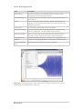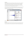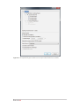
1
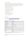
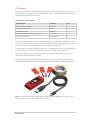
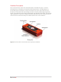
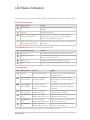
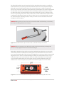
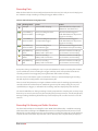
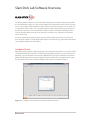
User Manual
Vibration - Temperature - Pressure
Data Logger
Table of Contents
General Information. . . . . . . . . . . . . . . . . . . . . . . . . . . . . . 3
Copyright. . . . . . . . . . . . . . . . . . . . . . . . . . . . . . . . . . . . . . . . . . . . . . . .
Warranty . . . . . . . . . . . . . . . . . . . . . . . . . . . . . . . . . . . . . . . . . . . . . . . .
Safety Precautions . . . . . . . . . . . . . . . . . . . . . . . . . . . . . . . . . . . . . . .
Introduction. . . . . . . . . . . . . . . . . . . . . . . . . . . . . . . . . . . . . . . . . . . . .
Overview of Features. . . . . . . . . . . . . . . . . . . . . . . . . . . . . . . . . . . .
Specifications. . . . . . . . . . . . . . . . . . . . . . . . . . . . . . . . . . . . . . . . . . . .
Kit Contents . . . . . . . . . . . . . . . . . . . . . . . . . . . . . . . . . . . . . . . . . . . . .
Hardware Description. . . . . . . . . . . . . . . . . . . . . . . . . . . . . . . . . . . .
3
3
3
4
5
5
6
7
Quick Start Guide. . . . . . . . . . . . . . . . . . . . . . . . . . . . . . . . . 8
LED Status Indication. . . . . . . . . . . . . . . . . . . . . . . . . . . . . 9
Transportation & Storage Requirements . . . . . . . . . . 10
Pre-Operation. . . . . . . . . . . . . . . . . . . . . . . . . . . . . . . . . . . 11
Charging Instructions. . . . . . . . . . . . . . . . . . . . . . . . . . . . . . . . . . . 11
Battery Level Check. . . . . . . . . . . . . . . . . . . . . . . . . . . . . . . . . . . . . 11
Configuration. . . . . . . . . . . . . . . . . . . . . . . . . . . . . . . . . . . . . . . . . . . 12
Time Formats. . . . . . . . . . . . . . . . . . . . . . . . . . . . . . . . . . . . . . . . . . . 13
Triggering Options. . . . . . . . . . . . . . . . . . . . . . . . . . . . . . . . . . . . . . 14
Device Identification. . . . . . . . . . . . . . . . . . . . . . . . . . . . . . . . . . . . 15
Operation. . . . . . . . . . . . . . . . . . . . . . . . . . . . . . . . . . . . . . . 16
Operational Environment . . . . . . . . . . . . . . . . . . . . . . . . . . . . . . . 16
Mounting Instructions . . . . . . . . . . . . . . . . . . . . . . . . . . . . . . . . . . 17
Recording Data. . . . . . . . . . . . . . . . . . . . . . . . . . . . . . . . . . . . . . . . . 19
Recording File Naming and Folder Structure. . . . . . . . . . . . . 19
Slam Stick Lab Software Overview. . . . . . . . . . . . . . . . 21
Configure Device . . . . . . . . . . . . . . . . . . . . . . . . . . . . . . . . . . . . . . . 21
Data Analysis . . . . . . . . . . . . . . . . . . . . . . . . . . . . . . . . . . . . . . . . . . . 23
Menus and Options. . . . . . . . . . . . . . . . . . . . . . . . . . . . . . . . . . . . . 27
Troubleshooting . . . . . . . . . . . . . . . . . . . . . . . . . . . . . . . . 37
Product Support. . . . . . . . . . . . . . . . . . . . . . . . . . . . . . . . . . . . . . . . 38
General Information
Copyright
This manual, software and the design data which it describes are copyright with all rights reserved.
None of the data may be copied without the express written consent of Midé Technology
Corporation. Refer to Midé Technology Corporation’s full Copyright Policy at http://www.mide.com/
legal/legal_copyright.php for the full legal terms in regard to this copyright.
Warranty
Midé Technology Corporation warrants that the Slam Stick X will be free from defects in
workmanship and materials in normal use and operation within one year from date of shipment.
This warranty only applies when the Slam Stick X is installed, maintained, and repaired in
accordance with all of the directions, instructions, diagrams, safety warnings, cautions, and other
notices set forth in this manual, and if not damaged by persons, actions, or inactions unrelated to
Midé. In the event of any such defect of which Midé is informed in writing within such one year
period, Midé’s sole responsibility is, at Midé’s option, to provide a replacement Slam Stick X at no
cost to the Buyer upon the return of the defective product. Requests for compliance with this
express, limited warranty shall be honored only when made by the Buyer. Refer to the Terms and
Conditions at http://www.mide.com/legal/legal_terms.php#4 for the full legal terms in regard to
this warranty.
Safety Precautions
A number of warnings and cautions appear in the text of this technical manual. They are intended
to safeguard personnel and equipment from potential hazards or damage during equipment
installation, operation, and maintenance. These warnings and cautions will be presented in the
following manner.
WARNING: This represents an operating procedure, practice condition, statement, etc., which if not
strictly observed, could result in injury to personnel or long term health hazards.
CAUTION: This represents an operating procedure, practice condition, statement, etc., which if not
strictly observed, could result in damage to, or destruction of, equipment or a reduction in
performance.
Version No. 1.0
Section: General Information
3
In addition to the specific warnings and cautions included in this manual, Midé recommends that
all customers install, operate, and maintain the Slam Stick X in accordance with general safety
guidelines included in standards published by OSHA.
Introduction
The Slam Stick X has been specifically designed as a wireless vibration data logging system without
the need to be wired to an external system, for either the purpose of operation or data recording.
The Slam Stick X was designed to work in parallel with, or ideally replace, the cumbersome
instrumentation systems typically used to monitor and record vibrations. These systems require
accelerometers hardwired to signal processors and then subsequently to data acquisition units. The
Slam Stick X allows the user to capture vibration data without the need for wires or modification
to the vibrating structure. Logged data is easily viewed through Midé’s software package, Slam
Stick Lab. The user can quickly analyze the data and easily determine the vibration characteristics
of the monitored system. Correlating sudden accelerations to known changes in the environment
is possible with the time stamping information. The logger also measures and records temperature
and pressure data so that these can be monitored over time.
Configuring, charging, and downloading the data from the Slam Stick X to a PC or laptop can be
easily achieved through the use of a micro USB cable (included) and the Slam Stick Lab software
package. The device appears as an ordinary USB thumb drive, enabling “plug-n-play” use wherever
you go – no drivers to install and no special system privileges needed. This software package allows
the user to configure the recorder for different sample rates or triggering modes, quickly review
recorded vibration, temperature, and pressure data, and export recording data to .CSV format for
use with other analysis packages. A copy of the User Manual, Data Sheet, Quick Start Guide, and the
Slam Stick Lab software are included on the device for convenience. If a Calibration Certificate was
purchased, it will also be included on the device.
The Slam Stick X can be configured to record immediately, after a user-specified time delay, at a
specific time, or in response to a trigger condition (temperature, pressure, or g-level range). The
recording duration, sampling rate, and antialiasing filter cutoff frequency are all user configurable.
The Slam Stick X’s enclosure was designed to save weight and space so that the device can be
securely mounted through the use of double-sided tape on virtually any vibrating surface. The
enclosure includes one slot so that the Slam Sick X can be tied to a nearby structure to act as a
failsafe if it were to ever become dislodged. The enclosure also includes three through holes so that
it can be screwed onto an intended structure.
Midé has designed the Slam Stick X as the next evolutionary step from its original Slam Stick
vibration recorder. With the Slam Stick X, Midé has built in additional features, functionality, and
robustness while maintaining a small form factor and wireless portability. For more information on
the Slam Stick, the Slam Stick X, and a wide range of other products, please go to www.mide.com.
Any questions about Midé’s products can be asked by emailing [email protected] or
calling 781-306-0609.
Version No. 1.0
Section: General Information
4
Overview of Features
The Slam Stick X is a three axis vibration data logger capable of measuring and recording
accelerations at a very high sampling rate so that the user can perform detailed vibrational analysis.
A real time clock provides time stamps for all data recorded so that comparisons to real-world
events can be made. Pressure and temperature sensors are also included to provide additional
environmental data and triggering capabilities. Features include;
• Embedded Triaxial Accelerometer
• Configurable Sampling Rate up to 20 kHz
• Temperature & Pressure Sensors Included
• Time Stamped Data with Local Calendar Time
• Manual & Automatic Start/Trigger Modes
• Rechargeable Battery Life of Over 4 Hours
• Lightweight (40 grams)
• USB Interface for Set-Up & Data Download
• Analysis Software Included
• Temperature Compensating Accelerometer
• 5th Order Hardware Anti-Aliasing Filter
• Calibration Certificate Available
Specifications
For a more detailed overview of the product’s specifications, please refer to the Slam Stick X
datasheet available at http://www.mide.com/pdfs/slam-stick-x-datasheet.pdf.
Table 1: General Slam Stick X Specifications
Specification
Slam Stick X
Axes Measured
X,Y,Z
Max Acceleration
25 - 100g
Frequency Response
2Hz - 4kHz
Sampling Rate
100 Hz to 20 kHz
Max Recording
>12 hours @ 10 kHz
Storage Size
2 GB
Additional Sensors
Temperature & Pressure
Minimum Operating Temperature
-40 C
Maximum Operating Temperature
80 C
Dimensions
L=3.00 in (76 mm) | W=1.18 in (30 mm) | H=0.59 in (15 mm)
Mass
40 grams
Lifetime
3 years
Triggering
Time delay, calendar date/time, pressure, temperature,
acceleration
*Slam Stick X has several variants and higher acceleration levels available upon request.
** User selectable with provided software.
Version No. 1.0
Section: General Information
5
Kit Contents
Every purchase of a Slam Stick X includes the data logger, a micro USB cable, three 4-40 bolts, a roll
of double sided tape, and three plastic scraper blades. Table 2 assigns part numbers which will be
referenced throughout this user manual.
Table 2: Midé’s Slam Stick X Kit
DESCRIPTION
PART NO.
QTY
Slam Stick X Data Logger
LOG-0002
1
USB to Micro USB Cable
4868
1
4-40 Bolts, ¾” Long
96006A217
3
3M 950 Adhesive Transfer Tape, 0.75 in x 5 yd
3/4-5-950
1
Plastic Scraper Blades
095394100115
3
Midé recommends that the Slam Stick X be mounted with the included 3M 950 adhesive transfer
tape and/or 4-40 bolts. A roll of tape is included with the initial purchase; but additional rolls can be
purchased through a variety of distributors including Amazon and Digi-Key.
The included tape is used for calibration. Calibration is not valid if other tape is used. If modification
to the mounting environment is possible, 4-40 bolts can be utilized along with the tape.
The plastic scraper blades included with each kit are recommended for removing the tape and
cleaning the underside of the Slam Stick X.
Additional bolts can be purchased through McMaster-Carr. The part numbers for the tape, bolts,
and plastic blades included in Table 2 are the manufacturer part number used by the distributors.
Figure 1: Slam Stick X package includes the data logger, a micro USB cable, three bolts, a roll of
mounting tape, and three scraper blades for tape removal.
Version No. 1.0
Section: General Information
6
Hardware Description
Various external features of the Slam Stick X (LOG-0002) are identified in Figure 2. The three
mounting holes are included to use 4-40 bolts to help align the device. The LED indicator is a
bi-color LED (green and red) that is used to present to the user various states of the devic. The
X-button is used to initiate and end recordings and also to manually cycle through programmed
triggers. The coordinate system reference illustrates the axes directions of the device. The tie down
slot is included to use a zip tie or a string of some kind to tether the device to a nearby structure as
a failsafe if it were to become dislodged. The USB receptacle is for a micro USB cable.
Figure 2: The Slam Stick X is shown with various key features identified.
Version No. 1.0
Section: General Information
7
Quick Start Guide
This Quick Start Guide may be used as a reference document on the proper use of the device.
1. Plug in to charge
a. Connect the Slam Stick X to a computer via the USB cable provided.
b. Charge your device - refer to “Charging Instructions.”
2. Copy files to Computer
Copy Documentation, and Software folders to a directory on your computer. The
Documentation folder contains the User Manual, Data Sheet, and Quick Start Guide.
3. Open software
Open Slam Stick Lab.exe file from the Software folder on your computer.
4. Set rates & triggers
a. Refer to the section entitled “Configuration” for a detailed parameters explanation.
b. Refer to “Configure Device” for instructions and screen views.
5. Mount to surface
Prior to mounting the device, ensure that the intended environment is suitable by referring to
the section entitled “Operational Environment.”
The section entitled “Mounting, Instructions” provides detailed mounting instructions.
a. The most common form of mounting the device is with the Midé recommended doublesided tape (provided with your kit). Due to the low mass of the product and the strength of
the tape, this mounting method is sufficient for most applications.
b. Three mounting holes of the Slam Stick X allow it to be mounted with 4-40 bolts (included
with your kit), allowing the user to better align the device in a desired orientation.
6. Press X-button
Press the X-button to begin recording. If you have configured the device to wait for a trigger,
the device will begin waiting after the button is pressed. Refer to the “LED Status” section.
7. Plug in to view data
Following completion, the data recorded by Slam Stick X can be downloaded and viewed using
Midé’s Slam Stick Lab software. Details of the operation of this software are provided in the
section entitled “Slam Stick Lab Overview.”
The Slam Stick Lab software also enables the user to export the data to a CSV file if desired.
Version No. 1.0
Section: Quick Start Guide
8
LED Status Indication
The LED indicator designates battery life, specifies operating modes, and indicates potential errors.
When Connected to Power
LED
Battery Status
Action
Fully charged.
Disconnect from power and use the device for data
logging.
Charging.
Continue charging.
Battery cannot be charged due
to extreme temperature.
Allow the device to reach the allowed charging
temperature range (0°C to 45°C). If LED indication
persists, contact Midé for assistance.
Device not operating properly,
or not connected correctly.
Check connection, if problem persists, contact Midé for
assistance.
During Battery Check - Hold down button until LED turns off
LED
Battery Charge Level
Action
Above 75%.
The device should be capable to perform as desired.
Between 20 and 75%.
The device will work; but for a reduced period. Charge if
longer recording is desired.
Below 20%
Charge the device before operation or storage.
Battery is dead.
Charge the device before operation or storage.
During Operation
LED
Blinking Mode
Status
Action
No Light
Device is off or sleeping.
Mount the device and press the button,
or store the device.
2 Sec. Blinking Green to Yellow
Device is waiting for a
time-based trigger.
Allow it to wait for trigger or hold
down button to skip to next trigger or
recording.
1 Sec. Blinking Green to Yellow
Device is waiting for a
pressure or temperature
trigger.
Allow it to wait for trigger or hold
down button to skip to next trigger or
recording.
Rapid Blinking Green to Yellow
Device is waiting for an
acceleration trigger.
Allow it to wait for trigger or hold down
button to skip to recording.
Rapid Blinking Green
Device is recording.
Battery level is above 75%.
Allow it to continue recording or press
X-Button to end recording.
Rapid Blinking Yellow
Device is recording.
Battery level is below 75%.
Allow it to continue recording or press
button to end recording.
Rapid Blinking Red
Device is recording.
Battery level is below 20%.
Allow it to continue recording or press
button to end recording.
If you experience any issues, please refer to the “Troubleshooting” section.
Version No. 1.0
Section: LED Status Indication
9
Transportation & Storage Requirements
The Slam Stick X is an electronic device and therefore its performance, especially battery life, can be
severely impacted by the environment it is transported and/or stored in. Midé recommends that
the Slam Stick X be both transported and stored at room temperature, 20 to 25°C (68 to 77°F). It is
also recommended that the transportation and/or storage environment have a low, <50%, relative
humidity (RH).
CAUTION: Be sure to transport and/or store the device in an environment that does not expose it
to water, fuel, oil, wet paint or other liquids and contaminants that could damage the Slam Stick X.
Although Midé recommends transportation/storage at room temperature with low humidity, the
Slam Stick X has been tested in extreme environments to ensure robustness. This testing includes
exposure to -40°C for eight hours and 80°C for eight hours. Extreme humidity testing was also
completed which included exposure to an environment of 60°C and 95% RH, non-condensing, for
eight hours.
CAUTION: Although the data logger has been tested and proven to survive short durations of
extreme environmental conditions, prolonged exposure can drastically reduce battery life and
cause the device to be out of calibration.
If the Slam Stick X will not be used for an extended period of time, it is recommended to recharge
the device at least twice per year to prevent over discharge. More frequent recharging may be
required if stored at high temperatures.
Version No. 1.0
Section: Transportation & Storage Requirements
10
Pre-Operation
Prior to using the Slam Stick X for data logging, it will need to be fully charged and configured.
Charging Instructions
The Slam Stick X is charged by connecting the device to a USB power source with the USB to Micro
USB cable as shown in Figure 3.
CAUTION: Be certain to insert the USB to Micro USB Cable into the micro USB receptacle with
minimal force to prevent damage. Do not insert the cable at an angle because it can cause
damage to the receptacle. Do not hold the button down when connected to power.
Figure 3: The Slam Stick X is easily charged by using the provided USB to Micro USB cable.
The LED indicator will designate the battery charging state as specified in LED Status Indication
section. Once fully charged the LED indicator will display a constant green light. It is estimated that
a full battery charge will take one to two hours depending on the power source and the age of the
battery.
Battery Level Check
To check the battery charge level, press and hold the X-button for greater than three seconds while
unplugged from the PC. While the button is held down, the battery life will be indicated by the LED
color as specified in “LED Indication” section for approximately three seconds, after which time the
LED will turn off. Once the LED indication has ceased, releasing the button will return the Slam Stick
X to sleep mode.
NOTE: If only checking battery level, be sure to hold the button until the charge indication
completes. Pressing the button for less than approximately three seconds will initiate a recording.
Version No. 1.0
Section: Pre-Operation
11
Configuration
Several of the Slam Stick X’s recording variables are user-configurable in order to meet various
recording needs. Table 3 lists the configurable variables and describes what each represents. The
table also defines the range of values that can be entered by the user for each variable, and the
default values are also provided. Midé can also instruct the user to change the calibration variables
of the device if it is believed that it has gone out of calibration. Midé also offers a recalibration
service if desired. Please contact Midé at [email protected] if recalibration is needed.
Table 3: Configurable Variables of the Slam Stick X.
Variable Name
Description
Default
Value Range
Sampling
Frequency (fs)
The frequency at which the Slam Stick X
measures and records acceleration data.
5 kHz
100Hz – 20 kHz
Antialiasing Filter
Cutoff
Filters out any frequencies above this
value to prevent aliasing.
One fifth fs
10Hz to 20 kHz
Oversampling1
Hardware oversampling can be disabled
to return raw measurement as an
advanced option.
Enabled
Enabled or
Disabled
UTC Offset
The time difference between Coordinated
Universal Time (UTC) and the local time.
This value is used to display correct file
timestamps on the device.
0
UTC-12 to
UTC+12
Wake After Delay
Adds a delay between when the X-button
is pressed and the device begins
recording.
No delay/
trigger
0 – 86400 s
Wake at
Specific Time
Local time and date at which recording
will begin after the X-button is pressed.
No delay/
trigger
Anytime in the
future
UTC Time
If set, the wakeup time can be entered
directly in UTC. If cleared, wakeup time
entry is in local time.
Disabled
(local time)
Enabled or
Disabled
Recording
Duration2
Limits the duration of each recording to
the desired value.
No limit
0 – 86400 s
Re-triggerable3
If the recording duration is limited, the
device can be programmed to be retriggerable, where after a recording it
begins waiting for the programmed
triggers again.
Disabled
Enabled or
Disabled
Pressure Trigger
(Low)
If enabled, initiate recording when
atmospheric pressure is at or below this
value.
No trigger
25 to 110 kPa
Pressure Trigger
(High)
If enabled, initiate recording when
atmospheric pressure is at or above this
value.
No trigger
25 to 110 kPa
Temperature
Trigger (Low)
If enabled, initiate recording when
temperature is at or below this value.
No trigger
-40 to +85C
Version No. 1.0
Section: Pre-Operation
12
Temperature
Trigger (High)
If enabled, initiate recording when
temperature is at or above this value.
No trigger
-40 to +85C
Accelerometer
Trigger (Low)
If enabled, initiate recording when the
negative-going g-level on any axis meets
or exceeds this value.
No trigger
-0g to -max
acceleration
Accelerometer
Trigger (High)
If enabled, initiate recording when the
negative-going g-level on any axis meets
or exceeds this value.
No trigger
+0g to +max
acceleration
Accelerometer
Window4
The device will monitor acceleration
levels on each axis and begin recording
when the g-level on any axis exceeds this
value.
No trigger
0 to ± max
acceleration
In the oversampling disabled mode, output resolution is limited to 12-bit.
1
It will record until the battery life expires or the recording duration length is reached, whichever occurs sooner.
2
It will remain in this state until the device is plugged into power.
3
Note that this maximum g-level trigger depends on the accelerometer variant purchased.
4
Time Formats
The Slam Stick X’s onboard realtime clock, and timestamps embedded within recording files,
are always stored in UTC (Coordinated Universal Time) internally. This provides a standard
representation which can be used and shared internationally without needing to know the
timezone or special conditions (e.g. Daylight Savings Time) in effect when/where the recording
was made. For most practical purposes, UTC and GMT (Greenwich Mean Time) can be considered
equivalent.
In the Slam Stick Lab software, times are displayed and entered in local time by default, using your
computer’s timezone and DST setting (if applicable). The “UTC Time” configuration item can be used
to enter a wake-up time trigger directly in UTC, if desired, and the “View -> Show Absolute UTC
Time” option in Slam Stick Lab can be used to display recording times directly in UTC.
The file creation times displayed by your computer operating system’s file manager are always
in local time. The “Local UTC Offset” (timezone) configuration item is used *only* to determine
the appropriate local time value when creating the file. This file creation timestamp is for display
purposes only and does not affect the UTC timestamps actually recorded inside the file. Recording
files can be copied, moved, renamed and otherwise processed without worrying about altering the
internal timestamp data.
NOTE: Due to the way some operating systems such as Microsoft Windows handle file timestamp
information, the displayed timestamp may differ slightly (typically by one hour) from the actual
creation time depending on whether Daylight Savings Time is in effect. This offset does not affect
the file’s internal timestamp data.
Version No. 1.0
Section: Pre-Operation
13
Triggering Options
The Slam Stick X can be configured with one or more trigger conditions, delaying the start of
recording until the desired operating conditions are met. If multiple triggers are enabled, they are
processed in the following order:
1. Calendar Wake or Time Delay
2. Pressure and/or Temperature window
3. G-Level Trigger.
Once each trigger condition has been met, processing will advance to the next active trigger in
this list (the previous condition is no longer monitored). Recording will start once the final enabled
trigger condition has been satisfied, even if some of the previous triggers’ conditions are no longer
present when the final trigger occurs.
For example, the user inputs a calendar wakeup of today at 5 PM, a pressure trigger at 70 kPa, and a
g-level trigger of 5 g on any axis, then activates the Slam Stick X by pressing the button. The device
will first sleep until the Calendar Wake; other conditions during this time have no effect. Then the
device will wait for the pressure/temperature condition. Following the pressure or temperature
trigger the device will then wait for the g-level condition. Once the g-level condition is met the
device will begin recording.
Triggering Multiple Recordings
Normally, the Slam Stick X turns off at the end of a recording, requiring the X button to be pressed
again to initiate a new recording cycle. The “Re-Triggerable” setting can be used to automatically
re-arm the triggers after recording and take multiple recordings in a row. This can be used for
unattended recording of multiple events or recording at a specified interval. In order to use this
feature, a recording time limit must be set so that the first recording will actually stop before the
battery or storage capacity runs out.
To automatically record at a specific interval, set “Wake after delay” to the desired idle time
between recordings, and set the recording time limit to the desired recording duration. The total
interval between the start of each recording will be the sum of the delay and recording times.
These settings can also be used with the pressure/temperature or g-level triggers. Setting “Wake
after delay” can be used to enforce a latent period between each triggered recording in order to
avoid immediately retriggering if the trigger condition persists longer than the desired recording
duration.
Bypassing Triggers
When the Slam Stick X is waiting for a trigger condition, press and hold the X-button for at least
one second to manually bypass the trigger, automatically advancing to the next trigger or initiating
recording. Likewise, pressing the X-button during active recording will terminate recording
(including any multi-recording cycle) and shut off the device, regardless of the configured recording
time limit or re-trigger setting.
Configuration is performed using the Slam Stick Lab software; please refer to the section entitled
Configure Device.
Version No. 1.0
Section: Pre-Operation
14
Device Identification
The Slam Stick X contains internal identification information that is accessible using Midé’s
Slam Stick Lab software package. The information is stored internally and will not be erased by
reformatting the device or updating the firmware - please refer to “Configure Device” in the Slam
Stick Lab Overview” section to see how to access this information.
A sticker is also included on the exterior of the device to identify the part number and serial
number. If a calibration was purchased, there will also be a calibration sticker that indicates the
calibration date and expiration date.
LOG-0002-100G
Serial No.: 0001
Cal Identity: 0001
Cal Date: /201
Figure 4: Identification and calibration stickers
Midé logs all devices that are manufactured and keeps all pertinent information about each unit. If
provided the serial number, Midé will be able to list all of the information on the particular unit.
Note that the part number is an expanded number from the Slam Stick X overall part number,
LOG-0002. This part number, in the format LOG-0002-MAXG, identifies the maximum acceleration
range of the accelerometer. The Slam Stick X is available in a range of maximum measurable
accelerations; but note that the lesser the measurable acceleration range is the greater the
sensitivity and accuracy will be. The numbers ‘MAXG’ refers to the maximum measurable
acceleration level in gs. For example a part numbered LOG-0002-100G indicates a Slam Stick X with
a maximum measurable acceleration of 100 g. A part numbered LOG-0002-025G indicates a Slam
Stick X with a maximum measurable acceleration of 25 g.
Version No. 1.0
Section: Pre-Operation
15
Operation
Operational Environment
The Slam Stick X is rated to operate between -20°C and 60°C. Operation outside of this temperature
range is possible; but the device will mark all recorded data outside this range as potentially
inaccurate. It is not recommended to use the device in an environment where temperatures exceed
80°C or drop below -40°C. The device can operate in humid environments as well, from 0-95% RH,
non-condensing. Operation in low pressure environments is also achievable down to 25 kPa.
The Slam Stick X has been demonstrated to withstand shock accelerations in excess of 250 g.
The double sided tape Midé recommends has also been tested to ensure that the device remains
mounted and secure for these large shock events. The tape has also been demonstrated to survive
severe vibrational environments of over 75 g, vibrating at 1,000 Hz. Midé recommends mounting
the device with screws if the environment has more severe shock and vibration levels.
The Slam Stick X is only dust proof and therefore should not be submerged or subjected to direct
fluid spray. Midé recommends applying a layer of removable tape over the USB receptacle if the
environment is especially dusty of if there is a known risk of fluid spray.
CAUTION: Do not expose the device to water, fuel, oil, wet paint or other liquids and contaminants
that could damage the Slam Stick X.
The Slam Stick X has been EMI tested and qualified to the United States Military Testing Standard for
Electromagnetic Compatibility (MIL-STD-461F). Test results available here: Test Report (27MB PDF).
Although the Slam Stick X has been demonstrated to survive harsh environmental conditions, it is
still an electronic device and care should be exercised when determining where to use the device.
It is also recommended to reduce the total duration the device is subjected to environmental
extremes.
CAUTION: Operation of the Slam Stick X outside of the recommended environment will void the
warranty and could also cause the device to be out of calibration.
If you are unsure if the Slam Stick X can survive your intended operational environment, please
contact Midé for assistance. A technical representative can be reached at [email protected].
Version No. 1.0
Section: Operation
16
Mounting Instructions
The Slam Stick X should be mounted with 3M Adhesive Transfer Tape 950. The tape should be
applied to the Slam Stick X prior to mounting; it is not recommended to apply the tape to the
intended surface first. A full three inch strip should be used. Prior to applying the tape to the
underside of the device, ensure that the surface is fully cleaned and devoid of dust and small
particles. To clean the underside of the Slam Stick X Midé recommends using the plastic scraper
blades provided with each kit. A paper towel with a small amount of a cleaning compound such
as toluene or denatured alcohol should be used to clean up any remnants of particles unable to
be removed with the blades. The tape can be difficult to remove at times, 3M offers a product
specifically designed to aid the removal of adhesive which Midé recommends. This product, called
the 3M Stripe Off Wheel (part number is 07498), is available from a variety of distributors..
WARNING: Many degreasing and cleaning solvents are flammable and must be kept away from
open flames and sparks. Use only under well-ventilated conditions. Do not smoke while using
flammable solvents.
CAUTION: Ensure that any cleaning solvent does not contact the USB receptacle. Liquids, especially
cleaning compounds, have the ability to electrically damage the Slam Stick X device.
After applying the double sided tape to the underside of the Slam Stick X, the device may be
mounted to the intended surface for data logging. Be sure that the mounting surface is also clean
and devoid of any dust and small particles. After the area has been cleaned and is dry, the Slam
Stick X can be mounted. A few pounds of force should be exerted on the Slam Stick X by hand to
compress the tape and better fix the device in place.
CAUTION: The Slam Stick X has a plastic enclosure; therefore the user should not overstrain the
device when mounting it to a surface, or use a metal blade to clean the surface.
Be sure to note the mounting orientation of the Slam Stick X. Midé recommends taking a
photograph after mounting the device so that the orientation can be verified after data logging.
The membrane on the outside of the device includes a coordinate system reference, which is
further explained in Figure 5. If the device is being mounted in an environment with a preexisting
coordinate system, such as an aircraft, be sure to align the device’s coordinate system with that
of the environment. If this is difficult to align perfectly, note how the two coordinate systems
are positioned in relation to one another. This will help with data analysis and ensure that data
recorded on the device can be correlated to “real world” events known by the system/environment.
Figure 5: The X and Y axes are as indicated. The Z axis is in the direction “out of the page,”
orthogonal to the X and Y axes.
Version No. 1.0
Section: Operation
17
The Slam Stick X includes one tie-down slot. This slot is included so that a zip tie or a similar tiedown mechanism can be used to provide a failsafe if the device were ever to become dislodged.
Although tests performed by Midé indicate the recommended tape is capable of keeping the
device secure even when subjected to high accelerations and vibrations, this cannot be guaranteed
for all possible environments, mounting surfaces and vibration conditions. Therefore, use of the
tie-down mechanism is recommended to prevent the possibility of user injury or damage to the
device or its operating environment. The tie-down slots are metal-reinforced and have been rated
to withstand a pulling force of 50 pounds. The tie-down slots are not recommended for securing
the device directly to a vibrating structure, merely as a means to act as a failsafe in the event of
dislodgment. Refer to figure 6.
CAUTION: Although the tie-down slots have been reinforced with steel dowel pins, overstraining
these slots can damage the device’s enclosure.
Figure 6: Illustration of how a zip tie can be used as a fail safe to help secure device.
CAUTION: Failure to properly secure the device could result in personal injury or damage the
device or nearby equipment if it were to become dislodged.
Although the double sided tape has been tested and qualified to keep the device secure in harsh
environments, Midé has included three mounting holes in the Slam Stick X enclosure to enable a
more secure mounting method. These holes were designed for 3 x 4-40 screws, with a recommended
length of at least 11/16”, to be used for mounting. The holes have a bolt pattern of 0.93” x 2.75” as
indicated in Figure 7. It is recommended to still use the double sided tape when mounting with
screws to further stabilize the device and maintain consistency with qualification testing and
calibration. Do not over torque the screws, Midé recommends torquing the screws to 3 lbf-in.
Figure 7: The enclosure includes three through holes to enable mounting with 4-40 screws.
Version No. 1.0
Section: Operation
18
Recording Data
After the Slam Stick X has been configured, mounted and secured, it is ready to record. Simply press
the X-button to begin recording or waiting for triggers. Refer to Table 4.
Table 4: LED Indication During Operation.
LED
Blinking Mode
Status
Action
No Light
Device is off or sleeping.
Mount the device and press the
X-Button or store the device.
2 Sec. Blinking Green to Yellow
Device is waiting for a timebased trigger.
Allow it to wait for trigger or
hold down button to skip to next
trigger or recording.
1 Sec. Blinking Green to Yellow
Device is waiting for a pressure
or temperature trigger.
Allow it to wait for trigger or
hold down button to skip to next
trigger or recording.
Rapid Blinking Green to Yellow
Device is waiting for an
acceleration trigger.
Allow it to wait for trigger or hold
down button to skip to recording.
Rapid Blinking Green
Device is recording.
Battery level is above 75%.
Allow it to continue recording or
press button to end recording.
Rapid Blinking Yellow
Device is recording.
Battery level is below 75%.
Allow it to continue recording or
press button to end recording.
Rapid Blinking
Red
Device is recording.
Battery level is below 20%.
Allow it to continue recording or
press button to end recording.
At any time during a recording the user can press the X-button to stop the recording. If the button
is pressed while the device is waiting for a trigger it will skip to the next specified event. Once a
recording event has been triggered, pressing the button will end the recording.
The user can press the button again to reactivate the device, or to immediately begin recording.
This will depend on configuration, and adequate battery life.
There is a brief delay between pressing the X-button and the start of recording (approximately 1/2
second) to allow the accelerometer to settle during power-up. This startup delay, plus any userspecified delays or triggers, is reflected in the recording start time displayed by Slam Stick Lab.
The rate the LED flashes at during recording is loosely proportional to sampling rate, and may range
from once per several seconds (at very low sampling rates) to many times per second (at high rates).
During recording, the flashing of the LED may occasionally skip. This is normal and not a cause for
concern.
Recording File Naming and Folder Structure
The Slam Stick X will place recording files in the \DATA\ folder, followed by a subfolder consisting
of the date of the recording in YYYYMMDD format. Each recording’s filename will consist of “SSX”
followed by a number that increases for each recording, based on the number of seconds that have
elapsed since the start of that day. These files can be sorted by date or alphabetically to display in
Version No. 1.0
Section: Operation
19
the order they were recorded. For example, a recording performed on July 24, 2014, at 8:00am will
be at \DATA\20140724\SSX28800.IDE .
The Slam Stick X also contains a \SYSTEM\ folder, which houses the configuration file and various
system files. It is not recommended to alter or delete these files. If a system file was accidentally
deleted, it will be automatically recreated the next time the Slam Stick X is plugged in.
The Slam Stick X also contains a \SOFTWARE\ folder where the Slam Stick LAB executable file is
located, as well as a \DOCUMENTATION\ folder that contains the User Manual, Data Sheet, Quick Start
Guide, and Calibration Certificate (if purchased). Midé recommends copying all folders and data files
from your Slam Stick X to a local folder on your computer - then using the copied files.
The user may store his or her own files on the device, such as test procedures, copies of software or
manuals, or other materials. If this is done, please avoid placing any files in the \DATA\ or \SYSTEM\
folders. Note that placing large or numerous files may adversely affect the maximum recording rate
or capacity.
Version No. 1.0
Section: Operation
20
Slam Stick Lab Software Overview
The primary function of the Slam Stick Lab software application is to import and display data from
the Slam Stick X data logger. It is also used to configure the Slam Stick X to meet various recording
needs. A major feature of the software is that it operates asynchronously; data can be viewed as it
is read from the device or file. This is especially important due to the potential very large datasets
that the Slam Stick X can record (>500 million samples). Midé is committed to offering a robust
and user friendly software package to its customers; it welcomes any suggestions on potential
improvement areas.
To run the Slam Stick Lab package simply copy the software folder on the device onto the hard
drive of a local computer. The application file with the Slam Stick Lab logo, called Slam Stick Lab.exe,
can be double clicked to run the software.
Configure Device
While data recorders appear as USB storage devices, the Slam Stick Lab provides a more verbose UI for
selecting attached devices. Recorders are displayed by their filesystem path (e.g. a drive letter under
Windows), user-specified device name, factory-defined device type name, and device serial number.
Additional information about a device is displayed under the device list. To configure a device open
the drop-down menu, Device, and then Configure Device (Ctrl + D) as shown in Figure 7.
Figure 7: To configure a Slam Stick X, use the Device drop-down menu.
Version No. 1.0
Section: Slam Stick Lab Software Overview
21
The Configure Device dialog, shown in Figure 8, provides a UI for configuring the device, as well as
displaying more information about the device. The configurable variables are explained in more
depth in the “Pre-Operation” section.
Figure 8: Configuration of various variables is made possible through the device configuration
dialog box.
Under the General tab, various global properties of the recorder are displayed, such as the device
name and the desired sampling rate. Under the Triggers tab, the user can define the values for the
various trigger parameters. A recording can be triggered by sensor readings, an absolute time, or a
time relative to when the recorder is powered up. Under the Device Info tab, read-only information
about the device is displayed. The contents of this tab are dynamically-generated from the data
that the recorder makes available.
Also included in the configuration dialog box are buttons to return the general settings and triggers
to the default values. Configuration settings can also be saved and imported using the Import/
Export buttons. In both cases, the device name and notes will not be changed.
To complete the configuration of the device, hit the Apply button. A dialog box will appear
confirming the successful confirmation of the device.
Version No. 1.0
Section: Slam Stick Lab Software Overview
22
Data Analysis
Open Recording
To open a recording, use the File drop-down menu and select Open as shown in Figure 9. The
keyboard shortcut Ctrl+O can also be used to open a file. Please note that the software will open
the files faster if they have been copied onto a computer first.
Figure 9: Recording files (.ide) can be opened using the File drop-down menu.
Main Plot View
The main view is divided into several sections: the time navigator, the plot view, and the status bar
as shown in Figure 10.
Figure 10: The main view of the Slam Stick Lab viewer is shown.
Version No. 1.0
Section: Slam Stick Lab Software Overview
23
Time Navigator
The time navigator displays the entire recording interval and allows the user to zoom in and out of
a particular time range of interest. Figure 11 and Table 5 identify and explain various features of the
navigator.
Figure 11: The time navigator view enables the user to control the time range of the presented data.
Table 5: Various Features of the Time Navigator.
Title
Description
Timeline
The timeline displays the start and end times of the entire recording. This
display updates dynamically when importing data from the recorder.
Displayed Range
Markers
The blue markers indicate the range currently displayed in the Plot View.
These update dynamically when the Plot View is scrolled. These markers can
be dragged to quickly specify a range to display.
Zoom Buttons
The Zoom Out button increases the length of the range currently displayed
in the Plot View (the horizontal axis). The Zoom In button decreases the
length of the range currently displayed in the Plot View (the horizontal axis).
The Zoom to Fit button zooms out to fit the file’s entire time range.
The start time of the recording is counted from when the recording was first initiated by pressing
the X-button, not when the first sample is recorded. Therefore, the first recorded data sample
may not necessarily start at 0, especially when using a triggered mode. The time offset where the
recording starts can be used to determine how much time elapsed between the start of a recording
cycle and the trigger event.
Version No. 1.0
Section: Slam Stick Lab Software Overview
24
Plot View
The plot view enables the user to view the data recorded on the Slam Stick X and also to compare
various data channels with one another. The plot tabs can be dragged into various areas of the
viewer window to aid in the comparison of data channels. This is done by clicking on the shown
tab and dragging into the desired location as shown in Figure 12. The location that the plot will
appear will become shaded in blue, at this time the mouse can be released to redraw the plot in
that location.
Figure 12: Multiple plots can be viewed together by dragging tabs into different areas of the window.
Figure 13 and Table 6 identify and explain the various features available to the user in the plot view.
Figure 13: Various features of the plot view are identified.
Version No. 1.0
Section: Slam Stick Lab Software Overview
25
Table 6: Various Features of the Plot View.
Title
Description
Tab Bar
The Tab Bar shows a tab for each sample set. The tabs can be dragged
to reorder, and more than one plot can be shown simultaneously by
dragging a tab from the bar into the main view. Tabs can be dragged
from one tab bar to another.
Horizontal Axis Scale
and Scrollbar
The scrollbar below the horizontal axis scale moves the current timespan
displayed. Clicking and dragging on the horizontal axis scale bar allows
for precise adjustment.
Vertical Axis Scale and
Scrollbar
This scrollbar enables the user to control the range of vertical axis values
being presented.
Manual Time Entry
Fields
The start and end of a specific time range can be entered here to
accurately zoom into or out to an intended time range.
Vertical Zoom Buttons
These increase and/or decrease the scale of the vertical axis. The first
two, Zoom In and Zoom Out, scale by a fixed amount. The third button,
Zoom-to-Fit, adjusts the displayed minimum and maximum to best fit
the range of values currently displayed.
Vertical Plot Axis
The vertical axis displays the values of the respective plot’s data channel.
The units of this axis are displayed below the zoom buttons. Clicking on
this axis also enables the user to precisely adjust the viewable range.
Horizontal Plot Axis
The horizontal axis displays the time range of the respective plot. The
units of this axis are always in seconds.
Also note that a plot can be zoomed in by left clicking a box around the area of interest in the plot.
Right clicking in the plot window will incrementally zoom out.
Status Bar
A status bar is located on the bottom of the window to present information to the user during data
importing and about the plotted data. Due to the large potential file size of datasets recorded on
the Slam Stick X, it can take upwards of an hour to import the entire dataset. The viewer software
was designed to allow the user to dynamically view and export data as it is imported. The status
bar indicates to the user the progress of the data importing. Figure 14 and Table 7 identify and
explain the various features and information presented in the status bar.
Figure 14: The status bar presents valuable information to the user during data import and while
plotting data.
Version No. 1.0
Section: Slam Stick Lab Software Overview
26
Table 7: Various Features of the Status Bar.
Title
Description
Horizontal Position Display
When the mouse pointer is within a plot area the x coordinate of
the plot is displayed in the units of the plot.
Time Stamp Display
When the mouse pointer is within a plot area the time stamp of
the data points the cursor is over are displayed.
Vertical Position Display
When the mouse pointer is with a plot area the y coordinate of the
plot is displayed in the units of the plot.
Samples Imported
When the viewer is working in the background, this status
message displays the number of samples recorded during data
importing.
Progress Bar
This provides a visual display of the progress of the full data
import.
Cancel Button
This button enables the user to cancel importing during the
import process.
Menus and Options
The functionality listed here is accessed via the Slam Stick Lab’s drop-down menus.
Mean Removal and Buffer Minimum/Maximum/Mean
The Slam Stick X saves the minimum, maximum and mean of each “Buffer” of data that is written to
disk. A “Buffer” is about 4,000 data points, so the frequency of these is directly proportional to the
sampling rate. The Slam Stick Lab software enables the user to utilize the buffer information in two
ways.
First, it uses the buffer means to determine the DC offset of the accelerometer channel. The
default is to remove the total mean which is determined by finding the median of all of the buffer
means. The DC offset of the accelerometer drifts with temperature, however, for long recordings
where temperature is changing, it may be desirable to remove the “rolling mean.” This removes the
median of the buffer means for just a subset of the entire dataset to allow for this to compensate
as the DC offset drifts. The user can select the type of mean/median removal they’d prefer through
the Data drop-down menu as shown in Figure 15. If no mean removal is selected, there will be a DC
offset in the data.
Version No. 1.0
Section: Slam Stick Lab Software Overview
27
Figure 15: The “mean removal” is used to compensate for thermal DC drift of the accelerometer.
Buffer data is also utilized to help illustrate the moving maximum and minimum acceleration level
bands. The Slam Stick Lab does not plot every data point (discussed more in Section View Settings),
so when zoomed out of a dataset it can appear that the vibrations were less dense and/or less
severe than in actuality. The Buffer Maximum and Minimum display can help visualize how the
maximum and minimum acceleration levels are changing with time. This can be especially helpful
when plotting data over a long time period.
Figure 16: The buffer minimum and maximum lines display how the maximum and minimum
acceleration levels are changing with time.
When there are more buffers than the number of pixels on the screen, the Slam Stick Lab plots just
the buffer maximum and minimums as shown in Figure 17. This is done to enable faster drawing
times and to provide a clear visualization on the acceleration data extremes. The data used to
generate the shown plot was generated from a frequency sweep when sampling at 10 kHz. The
sweep is very similar to the one shown in Figure 16; but for that plot, the device was only sampling
at 1 kHz.
Version No. 1.0
Section: Slam Stick Lab Software Overview
28
Figure 17: When there are more buffers then pixels on the screen, the Lab will plot all the buffer
max and minimums instead of data points for optimization purposes.
Recording Properties
Once a recording has been loaded, Slam Stick Lab can display information on the recording file
and on the device that generated the recording. To access this information click on Recording
Properties under the File drop-down menu or use the keyboard shortcut Ctrl+I as shown in Figure 18.
Figure 18: The recording properties dialog box is accessed in the File drop-down menu.
Version No. 1.0
Section: Slam Stick Lab Software Overview
29
The various tabs and information included in this dialog box are shown in Figure 19. The file size,
and recording start are some of the information included on the recording. The part number, date
of manufacturing, calibration date, calibration expiration date, and serial number are some of the
information included on the device used to generate the recording.
Midé also includes the sample rate, sensor range, and maximum and minimum value of each
channel. The time at which the maximum and minimum value occurred is also provided. In the
Calibration tab there are the equations used to calibrate the raw data. The univariate equation is
applied to all accelerometer channels to convert the raw signal to gs. The ‘x’ in the equation is the
raw signal. The bivariate equations are the x axis, y axis, and z axis calibration in that order. In these
equations the ‘x’ is the raw signal already converted to gs, and the ‘y’ variable is the temperature
measured in degrees C.
Figure 19: The Recording Properties dialog box presents a lot of information on a particular
recording, and on the device used to generate the recording.
View Settings
The View drop-down menu provides various features and settings to the user to manipulate how
the plotted data is displayed. The features and keyboard shortcuts are shown in Figure 20 and
explained in Table 8.
Version No. 1.0
Section: Slam Stick Lab Software Overview
30
Table 8: View Setting Features.
Title
Description
Redraw Plots
When the window size is modified the plots don’t always redraw
automatically. This feature redraws all plots.
Edit Visible Ranges
This allows the user to manually enter the axis ranges for the selected
sensor channel.
Zoom
These are shortcuts to zoom in and out. Note that left clicking and
dragging a box in a plot window will zoom into that range and right
clicking will zoom out.
Set Plot Color
The color of the selected channel can be modified.
Antialiased Drawing
This scales up the number of data points plotted as specified in the
preferences dialog box. This will smooth out the plot lines.
Noisy Resampling
This tries to combat aliasing in plotted data by randomly “jittering”
around the number of data points between each plotted point.
Show Buffer Data
The buffer minimum, maximum, and mean can be toggled on or off.
Gridlines
The major and minimum gridlines can be turned on or off by the user.
Show Absolute UTC
Time
This will show the absolute UTC time in the status bar.
Figure 20: The View drop-down menu provides various settings and features to the user to
manipulate how the plotted data is displayed.
Version No. 1.0
Section: Slam Stick Lab Software Overview
31
Preferences
Under the Edit drop-down menu is the Preferences dialog box as shown in Figure 21. Preferences
include specifying the color of gridlines and buffer mean/maximum/minimum, modifying the
default on mean removal, the amount of time used to compute the rolling mean, whether or
not individual data points will be drawn (if the number of pixels on the screen is greater than
the number of points), the antialiasing scaling factor, the resampling jitter factor, and the value
precisions for the axes (number of significant digits of plotted data).
The Slam Stick Lab will also check for automatic updates at the user specified interval in this dialog
box. Various information and warning dialogs provide the option to prevent that dialog from
appearing again. Saving the Preferences with the Reset Hidden Dialogs and Warnings checkbox
checked will make all warnings visible again.
Figure 21: Preferences are selectable to improve the user experience.
Export CSV
One function accessible via the File drop-down menu is Export to CSV. This will bring up a dialog
box, as shown in Figure 22, which is used for selecting channels and the time range for export as
comma-separated values. Table 9 explains how the user can define what information to export.
Version No. 1.0
Section: Slam Stick Lab Software Overview
32
Figure 22: The export dialog box enables users to export data channels to a CSV file.
Version No. 1.0
Section: Slam Stick Lab Software Overview
33
Table 9: Various Features of the Export Dialog Box.
Title
Description
Channel Selector
The various sensor data channels/sub-channels are listed in a hierarchical
format. Different sub-channels of the same channel can be exported
together; sets of channels/sub-channels with different sample rates must
be exported separately.
Range Selector
Select time ranges of samples can be selected for export. The number of
samples within the specified interval is also displayed. If All is selected, all
samples in the full time range of the dataset will be exported. If Visible
Time Range is selected, the range displayed in the main view will export.
If Specific Range is selected an explicitly-defined interval will export.
Mean Removal
The user has the ability to select what type of mean removal to apply for
the exported data.
Include Column
Headers Box
If checked, the first row of the exported CSV will contain the column
names.
Absolute UTC
Timestamps
If checked, the time column will display as the UTC timestamps (time 0 is
the start of 1961).
Use ISO Time Format
If checked, this will make the UTC timestamps more human-readable to
read as the date and time within the day.
Render FFT and Spectrogram
The Slam Stick Lab Viewer can also be used to render a Fast Fourier transform (FFT) or spectrogram
(2D FFT). The spectrogram slices the recording into shorter time segments and performs FFTs for
each time segment to display the frequency content over time as a surface plot. This may help
provide a clearer picture of vibration events over time, for example, differentiating constant or
repeating shock/vibe events from high-amplitude but non-repetitive events, even though they may
produce similar amplitude peaks in the 1-D Fourier results.
Because a recording can contain tens of millions of individual samples, the user interface (UI)
provides a means of selecting a specific interval to calculate an FFT or spectrogram for. Also, the
spectrogram UI allows for the selection of the number of slices per second in the spectrogram
calculation. The Render FFT dialog and the Render Spectrogram dialog have much of the same
functionality as the Export CSV dialog; as shown in Figure 23. Table 10 explains how to perform the
FFT or spectrogram analysis.
Version No. 1.0
Section: Slam Stick Lab Software Overview
34
Figure 23: The render FFT and render spectrogram dialog box allows the user to specify a range of
data to perform the analysis.
Table 10: Various Features of the FFT and Spectrogram Dialog Boxes
Title
Description
Channel Selector
This functions almost identically to its counterpart in the Export CSV
dialog. As with the export, FFT data for sets of channels/sub-channels with
different sample rates must be computed separately.
Range Selector
This functions almost identically to its counterpart in the Export CSV dialog.
This area also displays warnings if the number of samples in the specified
time range is likely to require more memory than is available. Because this
is a very rough estimate, these messages are only warnings and will not
prohibit an attempt to compute FFT data from an overly-large dataset.
Sampling Window
Size
FFT computation is done via Welch’s Method, utilizing a size-limited
sliding window. The size of the window can be adjusted; a smaller window
may conserve memory at the cost of increasing the minimum frequency
computed.
Slices Per Second
This defines the number of slices per second the spectrogram calculator
breaks the data into. The greater the number of slices, the better resolution
of the plot but this comes at the expense of computation time and memory.
Version No. 1.0
Section: Slam Stick Lab Software Overview
35
Figure 24 provides sample plots using the Slam Stick Lab software. Midé used its shaker to
generate this data. In the test the shaker swept in frequency from 15 Hz to 4 kHz at a near constant
amplitude of 10 gs while sampling at 1 kHz. The FFT and spectrogram were generated for a subset
of that sweep as shown. After generating a FFT or spectrogram the Lab enables this data to be
exported to a CSV format for manipulation or further analysis.
Figure 24: Sample FFT and Spectrogram plots are shown. Midé performed a test on its shaker to
generate this data where it swept up in frequency.
Version No. 1.0
Section: Slam Stick Lab Software Overview
36
Troubleshooting
Some common problems that require simple fixes are presented in Table 11 for troubleshooting. If
you experience an issue that is not covered in this table or if the suggested actions do not resolve
the problem, please contact Midé to receive assistance.
Table 11: Troubleshooting Issues with Slam Stick X.
Problem
Potential Cause
Action
No LED activity after
pressing the X-button.
The battery charge is
depleted.
Plug the device into a power source to
charge the battery fully prior to use.
The LED may have been
damaged.
The device should still function as
normal but there will be no LED
indicators.
A recording was never
triggered.
Check the configuration settings to
ensure that a trigger value has not
been programmed. If it has, then this
trigger parameter may have never been
exceeded.
The device has run out of
storage space
Back up and delete some of the
previous data recordings.
The battery charge is
depleted.
Plug the device into a power source to
charge the battery fully prior to use.1
The structure the device was
mounted to experienced
significant shocks/vibrations.
Be sure to use the zip tie slots to
prevent the device from getting further
damaged after becoming dislodged.
It also may be best to use 4-40 screws
to keep the device secure if future
recordings are desired.
The device may have
experienced a direct impact
from a foreign moving
object.
Be sure to mount and use the device
in an environment that is devoid of
moving parts and objects that could
damage the device.
The temperature was too low
which ruined the integrity of
the tape bond.
Download and view the data recorded
by the device to determine if and when
the temperature dropped too low.
The X button may have been
pressed while connected to
power and the device is in
“bootloader” mode.
Disconnect the device from power.
Wait at least 30 seconds for the device
to reboot..
After mounting the
device and pressing
the X-button, there are
no new data files.
The Slam Stick X came
dislodged.
The LED is not on
when connected to
power.
Version No. 1.0
Section: Troubleshooting
37
The device does
not appear in “My
Computer” when
connected.
The USB cable is not
properly inserted, or debris is
interfering with contact
Check the connection to the device
and to your computer to ensure it
is properly plugged in. Remove any
pocket lint or other debris present in
the USB receptacle
There may have been water
and dust damage.
Contact Midé to receive further
assistance.
The device is still recording
or waiting for a trigger event.
Press the X button until any active
triggers or recording have been
canceled.
The LED blinks red
during or when
starting a recording
Less than 20% battery charge
remains. If the battery charge
is too low to begin recording,
the Slam Stick X will emit 3
red blinks and shut down
Plug the device into a power source to
charge the battery fully prior to use.
Microsoft Windows
presents a dialog
prompting to scan
and fix the Slam Stick
X drive
Some Windows versions
present this dialog for some
drives not formatted by
Windows.
This message is harmless; the user may
either proceed with or cancel the scan.
In rare cases, when recording with a low battery, the battery power may run out before the Slam Stick X can finish
1
closing the recording file. If this occurs, the file may not appear even though some data was successfully recorded.
If the recording contains important data, a disk utility such as Windows chkdsk.exe may be used to recover the file
(enable display of hidden files to see the recovered file). Otherwise, the Slam Stick X can simply be reformatted.
Important: Do not use disk utilities to perform “bad sector” tests on the device. Not only is this
type of test not suitable for Flash media, the utility may incorrectly detect “bad” sectors on the
device due to the special mechanism the device uses to provide dynamic data via virtual files (such
as the clock setting and device information).
Product Support
For technical support, repair, and returns please contact Midé’s Slam Stick X sales department at
781-306-0609 extension 239. We can also be reached by email at [email protected].
Please note that product specifications are subject to change without notice. This often occurs due
to Midé’s continued effort to improve the features and functionality of this product. For software
updates, up-to-date user guide, datasheet and other product information please visit our website
at www.mide.com. Midé’s sales and technical staff would also be happy to help with any inquires of
updated product information.
Midé
200 Boston Avenue,
Suite 1000,
Medford MA, 02155.
Email: [email protected]
Phone: +1 781-306-0609
Version No. 1.0
Midé Technology is an ISO 9001:2008 Certified Company.
Section: Troubleshooting
38