1
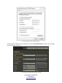
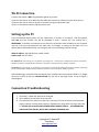
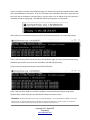
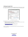
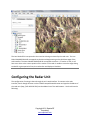
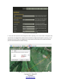
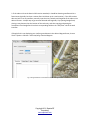
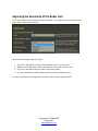
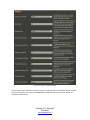
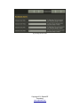
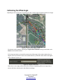
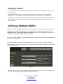
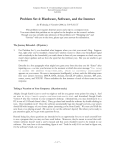
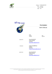
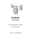
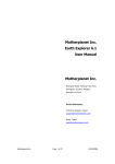
User Manual - SpotterRF M600
Introduction
M600 Required Components
Physical Setup
Direct Wire Connection
Setting Up the PC
Wi-Fi Connection
Setting up the PC
Connection Troubleshooting
Setting up Google Earth
Configuring the Radar Unit
Adjusting the Sensitivity of the Radar Unit
Calibrating the Offset Angle
Displaying Trackers
Setting up Multiple M600’s
Introduction
The M600 is a light-weight (about 3 ½ lb), medium range (1 km) Micro Surveillance Radar (MSR). A single
M600 can provide surveillance in all visibility conditions for up to 148 acres. This manual will guide you
through the setup process of an M600 radar unit.
Copyright 2011 SpotterRF
Proprietary
www.spotterrf.com
M600 Required Components
1.
2.
3.
4.
5.
6.
M600 Radar
Mount
Passive Power over Ethernet Injector
Cigarette Lighter Adapter Power Cable
2 Cat5 Cables
Laptop with Google Earth and Firefox or Chrome browsers
Physical Setup
Placement of the radar unit will directly affect its performance. Avoid pointing the radar at buildings
within 100 m or vehicles within 50 m (direct reflection from large and flat surfaces can reduce the
tracking performance of the radar).
Mounting the radar high will reduce reflections coming from the ground, and thereby improve its
performance. Mounting the radar unit high can also improve its line of sight. Mounting at 10 ft or more
is recommended for tracking a target on foot out to 1 km. Mounting on a vehicle will shorten the range
to roughly 800 m, depending on the terrain.
After mounting the M600, you can set up either a direct-wired connection or a wireless connection.
Copyright 2011 SpotterRF
Proprietary
www.spotterrf.com
Setting Up the PC
To establish a connection to the radar unit, the static IP address of your computer must be in the same
sub-network as the radar unit. For example, to connect to the radar unit at its default address
(192.168.254.254), your computer will use the following TCP/IPv4 settings (see fig. 2.):
IP address: 192.168.254.(any number 2-249)
Subnet mask: 255.255.255.0
For Windows XP, these settings can be adjusted by choosing Start > Control Panel > Network and Internet Connections >
Network Connections > Local Area Connection > Properties > Internet Protocol (TCP/IP) > Properties <<
For Windows 7, these settings can be adjusted by choosing Start > Control Panel > Network and Internet > Network and Sharing
Center > Change Adapter Settings > Local Area Connection > Properties > Internet Protocol Version 4(TCP/IPv4) > Properties <<
Copyright 2011 SpotterRF
Proprietary
www.spotterrf.com
Fig. 2: Screenshot of proper network settings
After setting the IP address, open a web browser and type 192.168.254.254 into the URL. You should get
the following page (see fig. 3):
Fig. 3: Screenshot of SpotterRF QuickStart web page
Copyright 2011 SpotterRF
Proprietary
www.spotterrf.com
Wi-Fi Connection
1) Assure the spotter is NOT lying flat down against any surface.
2) Connect the spotter to the M12 Ethernet cable then connect the cable to the case (See Figure 1).
3) Connect the case to either AC power or DC power using the appropriate cable.
4) Turn on the Wireless switch inside the pelican case.
Setting up the PC
From the Network Sharing Center on your Laptop click on Connect to a network. Find the Network
Called BA and click Connect. You will be prompted to enter a security key. The security key is:
PREMIUM93. To establish a connection to the radar unit, the wireless static IP address of your computer
must be in the same sub-network as the radar unit. For example, to connect to the radar unit at its
default address (192.168.254.254), your computer will use the following TCP/IPv4 settings:
WLAN IP address: 192.168.254.(any number 2-249)
Subnet mask: 255.255.255.0
For Windows XP, these settings can be adjusted by choosing Start > Control Panel > Network and Internet Connections >
Network Connections > Wireless Network Connection > Properties > Internet Protocol 4 (TCP/IP) > Properties
For Windows 7, these settings can be adjusted by choosing Start> Control Panel> Network and Internet> Network and Sharing
Center> Change Adapter Settings> Wireless network Connection > Internet Protocol 4 (TCP/IP)> Properties
After establishing a connection with the network, open a web browser that supports HTML 5 (i.e. Google
Chrome or FireFox 4) and type 192.168.254.254 into the URL. A web page similar to that of figure 3
should appear.
Connection Troubleshooting
Common mistakes while setting up the radar unit include:
1. The battery is dead and needs to be recharged
2. The IP address has not been set up correctly.
3. The cable from the radar unit to the case is too long. The case has a built in 19 Volt power
supply, however a 24 volt power supply is required when using cable runs longer than 100
ft. DO NOT USE AN ACTIVE POE (POWER OVER ETHERNET) SUPPLY -- A STANDARD POE
SUPPLIES OUTPUT 48V DC, WHICH WILL DAMAGE THE RADAR UNIT.
Copyright 2011 SpotterRF
Proprietary
www.spotterrf.com
If you are unable to connect to the QuickStart page, you should verify that the computer and the radar
unit have established a connection. To do this, first open up the Windows Start menu, type cmd into
the search bar at the bottom, and press Enter. Ping the radar unit's IP address from the computer's
command prompt by typing ping -t 192.168.254.254 and pressing Enter, as seen below.
If the radar unit is connected correctly you will see the following response in the command prompt:
If this is the case but you still cannot connect to the QuickStart page, you may have entered the wrong
IP address into the URL. Be sure to enter the address 192.168.254.254 exactly.
If you are not connected correctly your screen will look like this:
If this is the case there could be a number of problems associated with the physical setup and/or
network setup. Please verify that you followed the setup instructions exactly.
Remember: The default IP address of the radar unit is 192.168.254.254 -- You should be able to establish a connection
with the radar unit at this IP address (when it is directly connected to the radar unit as shown in figure 1). The static IP
address of your computer should never be the same as the IP address of the radar unit.
Copyright 2011 SpotterRF
Proprietary
www.spotterrf.com
Setting up Google Earth
To view trackers using Google Earth, you must tell Google Earth where to find the radar unit's output
file. In Google Earth, choose Add > Network Link. A window similar to figure 4 below should be visible.
Fig. 4: New Network Link in Google Earth
Edit the fields above marked in red according to the following specifications:
● Name: Choose a descriptive name. This name will appear under My Places > Places in the right
hand column (Figure 7) after adding the link.
● Link: http://(The IP address of the radar unit)/spotter.kml (e.g.
http://192.168.254.254/spotter.kml)
● Time Based Refresh: When set to Periodically, choose 1 secs.
Click OK. The network link just created should now be visible on the left hand side of Google Earth,
as seen in figure 5 below.
Copyright 2011 SpotterRF
Proprietary
www.spotterrf.com
Fig. 5: Active Spotter Link in Google Earth
The icon labeled FOV corresponds to the area that is being monitored by the radar unit. The icon
labled CALIBRATION LINE corresponds to the Azimuth Angle setting on the QuickStart page of the
web interface. The items labeled TRACKER ID XX correspond to trackers. If a tracker is alive, it will
have cross-hairs at the current position of the tracker. If the radar is unable to sense the target being
tracked for a given period of time, the tracker dies and displays a black dot.
Configuring the Radar Unit
The configuration of settings is done through the unit's web interface. To connect to the web
interface, launch Google Chrome or other HTML5 compatible web browser and type the IP address of
the radar unit (http://192.168.254.254) into the address bar of the web browser. You should see the
following:
Copyright 2011 SpotterRF
Proprietary
www.spotterrf.com
Fig. 6: Screen shot of QuickStart Page
1. First you must input the azimuth angle the radar is pointing. You can use either a compass or the
ruler function in Google Earth to determine the azimuth (in degrees) the Spotter is pointing. To do
this open the ruler function in Google Earth. Drop one point at the base of the radar and another
point out at the direction the radar is facing.
Fig. 7: Using Ruler to measure heading and range in Google Earth
Copyright 2011 SpotterRF
Proprietary
www.spotterrf.com
2. If the radar unit has the Garmin GPS receiver attached, it should be detecting satellites within a
few minutes (typically less than a minute after initial boot-up in a new location). If the GPS receiver
does not lock on to any satellites, manually input the time, latitude, and longitude of the radar unit in
decimal format. A simple way to get accurate latitude and longitude, is by opening Google Earth,
placing a new placemark at the location of the radar unit, and then copying and pasting the
coordinates from Google Earth into their corresponding fields on the “GPS/Time” tab of the web
interface.
If Google Earth is not displaying your Lat/Long coordinates in the decimal degree format, choose
Tools > Options > 3D View > Show Lat/Long > Decimal Degrees
Fig. 8: Using Placemarks to read GPS coordinates in Google Earth
Copyright 2011 SpotterRF
Proprietary
www.spotterrf.com
Adjusting the Sensitivity of the Radar Unit
There are two ways to adjust the Sensitivity of the Radar. The simplest way is on the Quick Start
page, under “Select Wind Condition”.
There are three settings under this option:
1.
2.
3.
4.
High_wind - Will detect vehicles and some walkers that are in open areas.
Medium_wind - Will detect walkers and vehicles; not crawlers, wind, or noise
Low_wind - Will detect vehicles, walkers and some crawlers.
No_wind - Will detect crawlers, walkers vehicles and all wind blown clutter
For more comprehensive settings open the “Sensor” tab, as seen in figure 6 below:
Copyright 2011 SpotterRF
Proprietary
www.spotterrf.com
Fig. 9: Sensor Page on the Web Interface
If there are particular distances that false trackers are appearing from wind blown objects or noise,
the user can set exclusion zones on the Zones tab to eliminate any tracks at those ranges. An
example is shown below:
Copyright 2011 SpotterRF
Proprietary
www.spotterrf.com
Fig. 10: Using exclusion zones
Copyright 2011 SpotterRF
Proprietary
www.spotterrf.com
Calibrating the Offset Angle
Depending on the environment surrounding the radar, trackers might be appearing offset at an angle.
Figure 11. Tracks with an Angular offset
The solution to this problem is adjusting the angular offset calibration setting as described on the
Sensor tab of the web interface.
To fix the picture above, you would first measure the offset angle of the trackers (about thirty six
degrees.) Since you want the tracks to be rotated clockwise, you would need to reduce the angular
offset calibration by thirty six.
Figure 12. Angular Calibration
When there is not enough traffic to know if the trackers are appearing offset at an angle, have a
person walk down a known path, and calibrate accordingly.
Copyright 2011 SpotterRF
Proprietary
www.spotterrf.com
Displaying Trackers
To change how tracks are displayed in Google Earth you can adjust two settings on the Output tab of
the web interface:
Adjusting KML Track Timeout will affect the amount of time an inactive tracker is displayed on
Google Earth. If the radar unit is monitoring an area with very little activity, using a KML track
Timeout of five minutes may be preferred so that past activity is more obvious. If there is more traffic
and the user is only interested in real time output, a KML Track Timeout of ten seconds or less is
recommended.
Setting up Multiple M600’s
If you want to set up multiple radars to be viewed on the same computer you will need to network the
M600s using a standard Ethernet switch. It is essential that care is taken to avoid interference. To
avoid interference, use units with different RF channels. The RF channel is labeled on the bottom of
your unit as a sticker numbered between four and eight.
Each radar must be assigned a unique IP address otherwise you will not be able to distinguish between
the radars on the network.
To do this you must connect to each radar individually and assign it a unique IP address. Open the
QuickStart page as you would in a single radar setup ( http://192.168.254.254) Next, go to the network
tab of the web interface.
Figure 15
Each Spotter must have a unique IP address but the same first 9 digits and the last three digits being
between 1 and 253. We suggest you edit the settings as follows:
Copyright 2011 SpotterRF
Proprietary
www.spotterrf.com
Setting Up the PC
To establish a connection to the radar unit, the static IP address of your computer must be in the same
sub-network as the radar unit. For example, to connect to the radar unit at its default address
(192.168.254.254), your computer will use the following TCP/IPv4 settings (see fig. 2.):
IP address: 192.168.254.(any number 2-249)
Subnet mask: 255.255.255.0
For Windows XP, these settings can be adjusted by choosing Start > Control Panel > Network and Internet Connections >
Network Connections > Local Area Connection > Properties > Internet Protocol (TCP/IP) > Properties <<
For Windows 7, these settings can be adjusted by choosing Start > Control Panel > Network and Internet > Network and Sharing
Center > Change Adapter Settings > Local Area Connection > Properties > Internet Protocol Version 4(TCP/IPv4) > Properties <<
Copyright 2011 SpotterRF
Proprietary
www.spotterrf.com