1
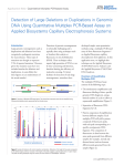
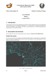
reference VT-P053-SUM-002-E
issue 1 revision 0
date 05/11/2008
VisioTerra
page 1 of 9
Tile Grabber
User's Manual
name
function
company
prepared by
Serge RIAZANOFF
Project Manager
VisioTerra
[email protected]
checked by
Grégory MAZABRAUD
Engineer
VisioTerra
[email protected]
approved by
date
signature
Serge RIAZANOFF
Project Manager
VisioTerra
[email protected]
" This document discloses subject matter in which VisioTerra has proprietary rights. Recipient of this document shall not duplicate,
use or disclose in whole or in part, information disclosed here on except for or on behalf of VisioTerra
to fulfil the purpose for which the document was delivered to him. ”
reference VT-P053-SUM-002-E
Tile Grabber
VisioTerra
User's Manual
issue 1 revision 0
date 05/11/2008
page 2 of 9
DOCUMENT STATUS SHEET
Issue
1.0
Date
Comments
Author
05/11/2008
First release
S. Riazanoff
" This document discloses subject matter in which VisioTerra has proprietary rights. Recipient of this document shall not duplicate,
use or disclose in whole or in part, information disclosed here on except for or on behalf of VisioTerra
to fulfil the purpose for which the document was delivered to him. ”
reference VT-P053-SUM-002-E
Tile Grabber
VisioTerra
User's Manual
issue 1 revision 0
date 05/11/2008
page 3 of 9
TABLE OF CONTENTS
1 PURPOSE .................................................................................................................................................... 4
2 PRINCIPLE .................................................................................................................................................. 5
2.1
STEP 1 - TILE CAPTURE ...................................................................................................................... 5
2.2
STEP 2 – CONSTRUCTION OF THE OUTPUT IMAGE ................................................................................ 5
3 PROCESSING PARAMETERS ......................................................................................................................... 6
3.1
SETTING THE BOUNDING BOX (UL,LR) .............................................................................................. 6
3.2
SETTING THE GROUND SAMPLING DISTANCE (GSD) ........................................................................... 7
3.3
SETTING THE OUTPUT FORMAT .......................................................................................................... 7
3.4
SETTING THE OUTPUT PROJECTION ..................................................................................................... 7
3.5
SETTING THE OUTPUT FILE NAME ....................................................................................................... 7
3.6
CROP PARAMETERS SETTING.............................................................................................................. 8
3.7
SAVING PARAMETERS ........................................................................................................................ 9
" This document discloses subject matter in which VisioTerra has proprietary rights. Recipient of this document shall not duplicate,
use or disclose in whole or in part, information disclosed here on except for or on behalf of VisioTerra
to fulfil the purpose for which the document was delivered to him. ”
reference VT-P053-SUM-002-E
Tile Grabber
VisioTerra
User's Manual
issue 1 revision 0
date 05/11/2008
page 4 of 9
1 PURPOSE
VTTileGrabber is an application enabling to capture the information displayed during your session on a
virtual globe. In its first release, VTTileGrabber manages the Google Earth virtual globe. The data
displayed during a session include raster and vector layers, placemarks that are provided by the user,
contributors on the net or by the virtual globe itself.
VTTileGrabber enables user to select:
§ the area of interest defined by the upper-left and lower-right corners,
§ the ground sampling distance (spatial resolution)
§ the format of the output image
§ the projection of the output image
§ the name and location of the output image file.
When parameter values are changed, VTTileGrabber checks
the validity of the parameters, the consistency of them,
compute elements of the processing and features of the
output file. These elements are printed in the “Informations”
panel.
§ Altitude giving at which elevation each tile will be
viewed to accommodate with the desired GSD.
§ Tiles giving the number of tiles required to capture the
whole bounding box.
§ Output image size that is an assessment of the
dimensions of the file to be produced.
§ Uncompressed size that gives the size of the output file
computed from the assessed image size.
" This document discloses subject matter in which VisioTerra has proprietary rights. Recipient of this document shall not duplicate,
use or disclose in whole or in part, information disclosed here on except for or on behalf of VisioTerra
to fulfil the purpose for which the document was delivered to him. ”
reference VT-P053-SUM-002-E
Tile Grabber
VisioTerra
User's Manual
issue 1 revision 0
date 05/11/2008
page 5 of 9
2 PRINCIPLE
Once the parameters have been set (see section “Processing parameters”) and user has launched the
acquisition pressing the “Get image” button, the station shall be left to VTTileGrabber and no action shall
be done on the computer (no mouse actions, no keyboard pressed). VTTileGrabber will fully control the
virtual globe application and the window manager.
VTTileGrabber will process the tile capture and the construction of the output image in two steps.
Work progress status is given in real-time on the icon representing VTTileGrabber. Step 1 is processed
when the progress value is in the range [0%,50%] while the range [51%,100%] corresponds to the second
step of the processing. When the processing is completed, no progress values are displayed anymore;,
VTTileGrabber application may be restored and the “Done.” message is displayed in its “Log” list. User
may collect the output file containing the image.
2.1
Step 1 - Tile capture
VTTileGrabber adjusts its view of the different tiles to set an overlay between adjacent tiles. Once the tile
is fully displayed (streaming rate equal 100%), VTTileGrabber captures the screen and clip the view
according to the crop parameters set by the user (see the section “Crop parameters setting”). This clipped
view is a tile which is saved in the temporary directory found in the configuration file
“VTTileGrabber.conf”
Tiles of the area of interest are captured in the order shown here below.
7
8
9
4
5
6
1
2
3
Because projection changes will be processed at the next step, a border is left around the area of interest
delimited by the bounding box. Such a behavior leads to consider more tiles than the minimum required
to strictly cover the area of interest.
2.2
Step 2 – Construction of the output image
The output image is computed in the projection defined by the user that differs from the projection used
by the virtual globe (vertical perspective in the case of Google Earth). VTTileGrabber processes this
projection changes that enables to “mosaic” the tiles without discontinuities.
" This document discloses subject matter in which VisioTerra has proprietary rights. Recipient of this document shall not duplicate,
use or disclose in whole or in part, information disclosed here on except for or on behalf of VisioTerra
to fulfil the purpose for which the document was delivered to him. ”
reference VT-P053-SUM-002-E
Tile Grabber
VisioTerra
User's Manual
issue 1 revision 0
date 05/11/2008
page 6 of 9
3 PROCESSING PARAMETERS
3.1
Setting the bounding box (UL,LR)
When they are know, user may directly input the
UL and LR geographic coordinates (longitude
and latitude) in the dedicated text fields. Values
are expected in decimal degrees.
One shall pay attention to set the location of the
lower-right corner (LR) consistent with the
location of the upper-left (UL): LR shall be
eastward and southward with regard to the UL location. When consistent values of UL and LR are set,
VTTileGrabber displays on the virtual globe a layer showing the selected bounding box.
An other convenient way to set the UL and LR
locations is provided using a “cross layer”
displayed in the virtual globe. This cross is
displayed exactly at the centre of the image area
and user shall pan the image to make it slip under
the cross. When the desired location is achieved,
user shall press the “Catch UL” or “Catch LR”
buttons.
" This document discloses subject matter in which VisioTerra has proprietary rights. Recipient of this document shall not duplicate,
use or disclose in whole or in part, information disclosed here on except for or on behalf of VisioTerra
to fulfil the purpose for which the document was delivered to him. ”
reference VT-P053-SUM-002-E
Tile Grabber
VisioTerra
3.2
User's Manual
issue 1 revision 0
date 05/11/2008
page 7 of 9
Setting the Ground sampling distance (GSD)
The spatial resolution of the output image may be set
entering a value in the “GSD” text field. This resolution
is a strictly positive decimal value given in meters in the
range ]0,10000].
Note that for a given bounding box (UL,LR), the value of the GSD directly impacts on the size of the
output image, on the number of tiles required to its capture, and therefore the time of the execution.
3.3
Setting the output format
The format of the output file may be chosen selecting
the appropriate item in the “Output format” Combo
box. The available formats are:
3.4
§
GeoTIFF in which particular tags of the version 1 revision 1.1 determines the coordinate reference
system (projection), ellipsoid, datum and other geodesic features.
§
TIFF version 6 producing an uncompressed image accompanied by the “.tfw” that gives the pixel
width (horizontal spatial resolution), the pixel height, and the coordinates (easting and northing) of
the upper-left corner. Note that this “tfw” file does not provide the projection.
§
PPM giving the RGB binary values without any geodetic information.
Setting the output projection
The coordinate reference system (CRS), sometimes
called projection, of the output image may be chosen
selecting the appropriate item in the “Output
projection” Combo box. The available CRS are:
3.5
§
Geographic in which points are referenced by the longitude and latitude coordinates with reference
to the WGS84 ellipsoid.
§
Plate Carrée in which points are referenced by the easting (X) and northing (Y) coordinates with
reference to the mean unitary spheroid with a radius equal to the mean of the semi-major and semiminor axes of the WGS84 ellipsoid.
§
UTM automatic (Universal Transverse Mercator) in which points are referenced by the easting (X)
and northing (Y) coordinates with reference to the WGS84 ellipsoid. The horizontal zone of the
UTM is automatically computed from the longitude coordinate of the image center.
Setting the output file name
Just before launching the capture, user may set the name of the file
that will contain the final image and the directory that will contain
this file.
A default name is proposed by VTTileGrabber. To enable
discriminating the various image captures, this name is composed
from the value of the UL coordinates (longitude and latitude) and
from the value of the GSD. The proposed name is refreshed in
real-time when user changes the value of these two parameters.
Syntax of the proposed name obeys to the following rule:
map_projection_ULX_ULY_GSD.ext
" This document discloses subject matter in which VisioTerra has proprietary rights. Recipient of this document shall not duplicate,
use or disclose in whole or in part, information disclosed here on except for or on behalf of VisioTerra
to fulfil the purpose for which the document was delivered to him. ”
reference VT-P053-SUM-002-E
Tile Grabber
VisioTerra
User's Manual
issue 1 revision 0
date 05/11/2008
page 8 of 9
Where:
§ projection is a short identifier of the selected projection (“Geographic” or “UTM_automatic” or
“Plate_Carree”).
§ ULX
is the longitude coordinates of the upper-left corner.
§ ULY
is the latitude coordinates of the upper-left corner.
§ GSD
is the ground sampling distance (also called spatial resolution).
§ ext
is the extension depending on the chosen format (“tif” for GeoTIFF or TIFF and
“ppm” for the PPM format).
Example: map_Geographic_-1.626658_43.579435_10.0m.tif
Parameters used to generate this image (see section “Saving parameters” above) are kept in an attached
configuration file “map_projection_ULX_ULY_GSD.conf”.
3.6
Crop parameters setting
Most of the virtual globes display decorations that user may want to
remove in the output image. VTTileGrabber enables user to define the
portion of the view that is to be kept when capturing the tiles.
To
define
the
clipping
parameters, one has to select the
“Crop parameters” of the
“Option” menu.
This tool displays a grey-level
copy of the image in the virtual
globe window, and in which a
red bounding box shows the
present values of the crop
parameters (see the figure
against).
top
left
In Google Earth, it is possible to
enlarge the image area removing
the left panel that shows the
layers. Such enlargement is
recommended.
right
botto
m
To remove this panel, deselect the “Lateral bar” in
the “Display” menu or more simply, just click on the
“Hide left panel” in the tool bar.
For each one of the sides (top, bottom, left, and
right), the location of the red lines may be changed
when the mouse pointer symbol is changed (see the
figure showing a zoom of the upper-left corner).
Crop parameters may be set to 0 selecting the “Reset
crop values to zero” in the “File” menu.
" This document discloses subject matter in which VisioTerra has proprietary rights. Recipient of this document shall not duplicate,
use or disclose in whole or in part, information disclosed here on except for or on behalf of VisioTerra
to fulfil the purpose for which the document was delivered to him. ”
reference VT-P053-SUM-002-E
Tile Grabber
VisioTerra
User's Manual
issue 1 revision 0
date 05/11/2008
page 9 of 9
When the crop parameters have been adjusted, the window shall be closed activating the “close” button
located at the upper-right of the window .
After having adjusted the crop parameters, it is recommended to save the values (see the section “Saving
parameters”). Crop values shall be set only once the first time VTTileGrabber is used. If parameters have
been saved, the same values of crop will be used each time VTTileGrabber will be run.
3.7
Saving parameters
All the processing parameters that can be set by the
user through the interface but also system
parameters like the temporary directory are stored
in the “VTTileGrabber.conf” file. This file is stored
under
the
user
directory
C:\Documents and Settings\user\ and under the
VisioTerra\VTTileGrabber sub-directory.
Contents of the configuration file are shown in the
figure on the right and may be changed using
whatever text editor. Nevertheless the standard way
to save the current values of the parameters is by
using the “Save parameters” of the “File” menu.
Note:
This configuration file could be replaced by an other valid configuration file. For example one of
the “map_projection_ULX_ULY_GSD.conf” attached to the produced image (see section
“Setting the output file name”). Such a replacement would enable to restore the parameters to the
values used to produce the image.
" This document discloses subject matter in which VisioTerra has proprietary rights. Recipient of this document shall not duplicate,
use or disclose in whole or in part, information disclosed here on except for or on behalf of VisioTerra
to fulfil the purpose for which the document was delivered to him. ”