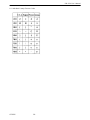
1
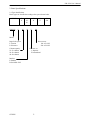
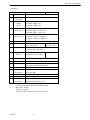
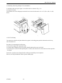
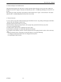
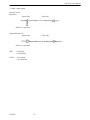
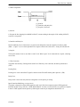
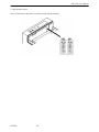
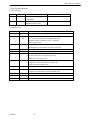
CITIZEN
User’s Manual
MINI DOT MATRIX PRINTER
MODEL
iDP-3530
Japan CBM Corporation
Information Systems Div.
iDP-3530 User’s Manual
IMPORTANT: This equipment generates, uses, and can radiate radio frequency energy and if not
installed and used in accordance with the instruction manual, may cause interference to radio
communications. It has been tested and found to comply with the limits for a Class A computing
device pursuant to Subpart J of Part 15 of FCC Rules, which are designed to provide reasonable
protection against such interference when operated in a commercial environment. Operation of this
equipment in a residential area is likely to cause interference, in which case the user at his own
expense will be required to take whatever measures may be necessary to correct the interference.
CAUTION: Use shielded cable for this equipment.
For Uses in Canada
This digital apparatus does not exceed the class A limits for radio noise emissions from digital,
apparatus, as set out in the radio interface regulations of the Canadian department of
communications.
CITIZEN
2
iDP-3530 User’s Manual
CONTENTS
1. Introduction ............................................................................................................................................................4
1-1 Features ............................................................................................................................................................4
1-2 Accessories.......................................................................................................................................................4
2. Basic Specifications................................................................................................................................................5
2-1 Type classifications ..........................................................................................................................................5
2-2 Features ............................................................................................................................................................6
3. External Appearance and Parts Descriptions..........................................................................................................7
3-1 External appearance and parts names...............................................................................................................7
3-2 Parts Descriptions.............................................................................................................................................8
4. Preparation............................................................................................................................................................10
4-1 Setting / Removing the Printer Cover ............................................................................................................10
4-2 The Ribbon Cassette Installation....................................................................................................................10
4-3 Loading and Changing the Paper ...................................................................................................................11
4-4 Attaching / Removing the Paper Cover and Stacker ......................................................................................12
4-5 Self Test Printing............................................................................................................................................12
4-6 Alarm and Paper Near-End Detection............................................................................................................13
4-7 General Cautions ............................................................................................................................................13
5. Serial Interface......................................................................................................................................................14
5-1 Specifications .................................................................................................................................................14
5-2 Connector Pin Assignment.............................................................................................................................14
5-3 Input / output Signals .....................................................................................................................................15
5-4 Data Composition...........................................................................................................................................16
5-5 Error Detection...............................................................................................................................................16
6. Parallel Interface...................................................................................................................................................17
6-1 Specifications .................................................................................................................................................17
6-2 Connector Pin Assignment.............................................................................................................................17
6-3 Description of Input / Output Signals.............................................................................................................18
6-4 Electrical Characteristics................................................................................................................................19
6-5 Timing Chart ..................................................................................................................................................20
7. Function Selection by Dip Switch ........................................................................................................................21
7-1 Dip-Switch (DS-1) Setting .............................................................................................................................21
7-2 Dip-Switch (DS-2) Setting .............................................................................................................................21
7-3 Dip-Switch Location ......................................................................................................................................22
8. Print Control Functions ........................................................................................................................................23
8-1 SI & SO Code.................................................................................................................................................23
8-2 Function Code ................................................................................................................................................23
8-3 Input Data Formats.........................................................................................................................................24
9. Initial Setting ........................................................................................................................................................26
10. Maintenance .......................................................................................................................................................26
11. Character Code Tables ........................................................................................................................................27
11-1 International Character Codes ......................................................................................................................27
11-2 Individual Country Character Codes ............................................................................................................28
CITIZEN
3
iDP-3530 User’s Manual
1. Introduction
The iDP 3530 is a dot impact printer which can be utilized for a wide range of applications including,
data communications terminals, P.O.S. terminals and kitchen printers. High speed performance is
made possible by a bi-directional printing system. Since this printer is compact, lightweight and equipped with
an abundance of functions, it can be easily employed for a variety of different tasks.
Before using your printer, please read this manual carefully to be certain you have an adequate understanding
of its operation.
1-1 Features
1)
2)
3)
4)
5)
Desktop compact dot impact printer.
High speed printing (Bidirectional printing system).
Black & Red 2 color printing and all black or purple printing.
Paper near-end detection function.
Low power consumption.
1-2 Accessories
1) Paper roll
2) Ribbon cassette
3) Rear cover
4) Paper Stacker
5) User’s manual
CITIZEN
1 Pc.
1 Pc.
1 Pc. (Friction model only)
1 Pc. (Pin tracter model only)
1 Pc.
4
iDP-3530 User’s Manual
2. Basic Specifications
2-1 Type classifications
Printer types are classified according to the system shown below.
iDP3530
iDP3535
F
P
F
23
28
40
40
R
P
R
F
J
F
120
220
120
Model
Paper feed system
F: Friction
P: Pin tracter
Column capacity
23: 23 columns
28: 28 columns
40: 40 columns
Power source
120: AC 120V
220: AC 220V
Character set
J: Japanese
F: International
Interface
P: Parallel
R: Serial RS-232C
CITIZEN
5
iDP-3530 User’s Manual
2-2 Features
1
2
3
Item
Print Method
Character
composition
Character
number
per line
4
Print speed
5
Character size
6
7
Line pitch
Paper size
8
Interface
9
Paper end
detector
iDP3530F
iDP3530P
Bidirectional serial dot impact method.
7 x 7 dots (Incl. Half dot).
23 columns: 230dot / line.
28 columns: 280dot / line.
40 columns: 360dot / line.
23 columns: approx. 4.0 line / sec.
28 columns: approx. 3.5 line / sec.
40 columns: approx. 3.0 line / sec.
23 columns: 1.8(W) x 2.4(H) mm
28 columns: 1.5(W) x 2.4(H) mm
40 columns: 1.36(W) x 2.4(H) mm
4.23 mm (1/6 inch)
76±0.5(W) x 80(Dia.)mm *1 76-89 (W) mm
3(W) x 3(Dia.)inch.
3.0-3.5 (W) inch.
P: Parallel interface (8 bit).
R: Serial interface (RS-232C).
When paper is near the end,
print operation is interrupted.
10
11
12
Ribbon cassette Two color (Black / Red) print. IR-61R / B *2
Paper winder Available as option (Ref. to 3-2 (8)).
Power voltage 120V ± 10% 60Hz (For United States).*3
230V ± 10% 50 / 60Hz (For Europe).
13 Power Consump. Approx. 30W.
14 Operation temp. 0ºC to 40ºC / 32ºF to 104ºF.
& humidity
10% to 85% RH.
15
Storage temp. -20ºC to 60ºC
16
Net weight
Approx. 2.8Kg (6.2ib)
17
External
160 (W) x 184 (D) x 173 (H)
dimentions
(without Knob and Rear cover)
Notes: *1 Paper weight of 45 kg refers to 1,000 sheets of 788 x 1,091 mm.
*2 Single color cassette ribbon is available as option.
Black print : IR-61B
Purple Print : IR-61P
*3 Power voltage setting is performed at the factory.
CITIZEN
6
iDP-3530 User’s Manual
3. External Appearance and Parts Descriptions
3-1 External appearance and parts names
Fig. 1
Fig. 2
CITIZEN
7
iDP-3530 User’s Manual
3-2 Parts Descriptions
(1) Power Cord
Insert the plug end into an electric outlet.
(2) Power Switch
Power is supplied to the printer by turning this switch on.
(3) Power Lamp
This lights up when the power switch is “ON” and goes out when turning “OFF”.
(4) SEL / ALARM Lamp
This lights up when the printers is in SELECT state ( ON-LINE) and goes out when
in DESELECT state (OFF-LINE). The printer can print out the data only when this
lamp is on. This lamp may blink on the following occasions.
1) When the paper roll in coming to near-end, the SEL / ALARM lamp keeps
blinking at interval of 1.0 second.
In this status, if you want to print out the data in the input-buffer, press the SEL
switch two times. First press is cleared an alarm condition (ALARM RESET)
and then one line print will be done by second press.
2) When the printer is in alarm state, this lamp keeps blinking at interval of 1/4
second. Remove the cause for alarm and press the SEL switch. (or re-switch the
power on).
(5) LF Switch
Paper feeding is performed when this switch is pressed
(in DESELECT status only). This is used when inserting the paper and for spacing
up etc.
(6) SEL Switch
When this switch is pressed, the printer enters SELECT (ON-LINE) status.
When pressed again, the printer enters DESELECT (OFF-LINE) status.
This switch is also used when clearing an alarm condition.
(7) I / F Connector
Connects through a cable to a computer etc. Please be certain that power to both the
printer and the computer are turned off when connection is made.
CITIZEN
8
iDP-3530 User’s Manual
(8) Cash Drawer or Paper Winder Connector
To be used to control the P.O.S. cash drawer or paper winder by DIP SWITCH
setting (Ref.7-1).
When this connector is used for each drawer solenoid voltage 24V, register over
36Ω, for paper winder, use CBM model AW-3.
Pin No
1
2
3
4
Connector Pin Assignment
Signal Name
Function
Vp
DC24V, 0.8A or less
VL
Solenoid
FG
GND
FG
GND
Connector
: Printer side
: 5045-04A (MOLEX)
(9) Printer Cover
Open when replacing the cassette ribbon and Paper.
(10) Manual Paper Feed Knob
Use to adjust the paper position (available only on pin tractor paper feeding model).
(11) Rear Cover
Cover for roll paper.
(12) Stacker
Basket for fan-fold paper.
CITIZEN
9
iDP-3530 User’s Manual
4. Preparation
4-1 Attaching / Removing the Printer Cover
Attaching and removing the printer cover as shown in Fig. 3.
Fig.3
4-2 The Ribbon Cassette Installation
To insert the ribbon, disconnect the power source beforehand. If printing has been continued for many
hours, be careful not touch printer head as it might be hot.
1) Remove the printer cover
2) While inserting the ribbon into the space between the print head and the ribbon guide, press the cassette into
the holder unit until it clicks into place. (Ref. To Fig. 4&5)
3) Turn the cassette ribbon knob in the direction of the arrow to take up slack in the ribbon.
Fig. 4
CITIZEN
Fig. 5
10
iDP-3530 User’s Manual
4-3 Loading and Changing the Paper
Using Paper Roll
1) Cut the paper in right angle to its longitudinal center line as shown in Fig. 7.
2) Insert the paper into insertion inlet on the rear side of printer.
3) Turn on the power switch and feed the paper by pushing the LF switch.
4) When the printing paper comes out of the clearance (paper cutter part) on the printer cover, fix the paper by
means of paper holder, then set in on the main unit.
Fig. 6
Using Fan-fold Paper
1) Remove the printer cover.
2) Set the imprint face of the paper down ward and put into the paper entrance.
3) If necessary to adjust the sprocket-wheel’s position, free the wheels using the lever on both side.
Slide them to the appropriate position, and lock them back.
4) Hook some of the paper’s perforations on the sprockets and forward the paper into the printer mechanism by
pulling and turning the paper-feed knob until the paper’s tip reaches the platen.
Fig. 8
CITIZEN
11
iDP-3530 User’s Manual
4-4 Attaching / Removing the Paper Cover and Stacker
1) Attaching and removing the paper cover and the stacker as shown in Fig. 9, 10.
2) Capacity of stacker
The maximum size of fun-fold paper sheaf which can be stored in this stacker is 3 to 3.5 (W) x 6 (H) x 1.6 (D)
inches.
Fig. 9
Fig. 10
4-5 Self Test Printing
Your printer has a built in self print function for purpose of checking print operation without the need for any
other external device.
Procedures for Actuating the Print Function
1) Be sure that a paper roll is properly loaded.
2) Confirm that the Ribbon cassette is properly installed and turn the power switch off.
3) Turn the power switch ON while pressing the LF switch, and release the LF switch after the self test operation
has begun.
In the above operation, the self print function will stop automatically when completed.
However, the self print function will not operate without paper.
CITIZEN
12
iDP-3530 User’s Manual
4-6 Alarm and Paper Near-End Detection
This printer has the paper near-end sensor to stop the operation when the paper comes to near-end, sending out
both BUSY and FAULT signals. This status is indicated by the SEL / ALARM lamp blinking at-an interval of 1.0
second.
If the printer goes alarm, the printer stops printing out and outputs FAULT signal – OFF-LINE state. This status
makes the SEL / ALARM lamp blink at an interval of 1/4 second.
4-7 General Cautions
1) Never operate your printer without inserting paper and ribbon cassette. Any printing without paper and ribbon
cassette may cause damage to printer head.
2) Replace ribbon cassette before it is worn out.
3) Be careful not to drop any foreign objects, such as paper clips, pins and the like into your printer.
It can cause mechanical trouble.
4) Nothing shall be placed on the ventilation slots of the printer.
5) Always place your printer on a stable desk which is set horizontal.
6) No organic solvent (thinner, benzene or the like) shall be used in sweeping clean the surface of the main body
case.
7) Make sure that the power of the printer is turned off whenever you do the following.
(1) Taking out any foreign matter which were dropped into the printer.
(2) Replacing the ribbon cassette.
CITIZEN
13
iDP-3530 User’s Manual
5. Serial Interface
5-1 Specifications
1) Synchronism
: Asynchronous
2) Baud rate
: 1200, 2400, 4800, 9600 BPS (Selected by user)
3) Composition of one word : Start bit : 1 bit
Data bit : 7 or 8 bit (selected by user)
Parity bit : Odd, even or parity (selected by user)
Stop bit : 1 bit or more.
4) Signal polarity
: RS-232C : Mark = Logic “1”
(-3V to -12V)
: Space = Logic “0”
(+3V to +12V)
4) Receiving Control (DTR signal)
: RS-232C : Mark = Data transfer not possible
: Space = Data transfer possible
5-2 Connector Pin Assignment
Pin No.
1
3
7
14
20
Notes:
CITIZEN
Signal
Name
FG
RD
SG
FAULT
DTR
Direction
Host / Printer
→
←
←
Function
Safety Ground
Received Data
Signal Ground
Printer ALARM Signal
Printer BUSY Signal
RS-232C
¡
¡
¡
1. The signal for RS-232C use are based on EIA RS-232C level.
2. Please always maintain the “Mark state”, when received data is not being transferred.
3. Compatible connector (D-Sub connector)
Printer side: Equivalent to AMPHENOL 17-13250
Cable side: Equivalent to AMPHENOL 17-23250
14
iDP-3530 User’s Manual
5-3 Input / output Signals
RS-232C Circuit
Input (RD)
[Printer side]
[Host side]
uPD4711 or equivalent
Output (DTR,FAULT)
[Printer side]
[Host side]
uPD4711 or equivalent
DTR
: (-8V) BUSY
: (+8V) READY
FAULT : (-8V) Normal
: (+8V) Abnormal
CITIZEN
15
iDP-3530 User’s Manual
5-4 Data Composition
[1] Start bit
[2] Data bits (and parity bit)
[3] Stop bit (1 bit more)
1) Start bit
1/2 bit past the line dropping from MARK to SPACE, a status reading is taken again. If the reading is SPACE,
a start bit is recognized.
2) Data bits and Parity bit
Data bit and Parity bit are checked out every bit form the half point of start bit. Signal level of these points
(Mark = 1, Space = 0) are read as input data. The sequence of these bit is Bit 0, Bit 1 ~ Parity bit from Start bit.
3) Stop bit
The stop bit consists of one or more bits at “mark” level. When “space” level is detected for a stop bit, a framing
error occurs.
5-5 Error Detection
The printer detects Parity, Framing and Overrun Error. When any error is detected, the data is printed out as
(7FH).
Framing Error;
Framing error occurs when SPACE signal is checked out at STOP BIT and the printer print out (7FH).
Parity Error;
Parity check is carried out only when user designates it on the printer pre-setting.
Input Control and Buffering; (over-run-error)
The printer is designed to output DTR signals for each word. If the host computer neglects DTR signal and
transmits the data, it may cause the “OVER-RUN ERROR”. In order to avoid such case, set up the host computer
to observe DTR signals from the printer by following the connector pin assignments described in 5-2.
CITIZEN
16
iDP-3530 User’s Manual
6. Parallel Interface
6-1 Specifications
1) Data Input System
: 8 bit parallel (Data 1-8)
2) Control Signal
3) Compatible Connector
: ACK, BUSY, STB, FAULT
: Printer side. To equivalent AMPHENOL 57-40360
: Cable side. To equivalent AMPHENOL 57-30360
6-2 Connector Pin Assignment
Pin No.
1
2
3
4
5
6
7
8
9
10
11
12
13
14
15
16
17
18
CITIZEN
Signal Name
STB
Data 1
Data 2
Data 3
Data 4
Data 5
Data 6
Data 7
Data 8
ACK
BUSY
GND
+5V Level
GND
GND
GND
Frame GND
Pin No.
19
20
21
22
23
24
25
26
27
28
29
30
31
32
33
34
35
36
17
Signal Name
Twisted Pair GND
″
″
″
″
″
″
″
″
″
″
FAULT
iDP-3530 User’s Manual
6-3 Description of Input / Output Signals
1. Input / Output Signals
Input Signals (To Printer)
DATA 1 : 8 bit signal (Positive logic)
DATA 2 : 8 bit signal (Positive logic)
DATA 3 : 8 bit signal (Positive logic)
DATA 4 : 8 bit signal (Positive logic)
DATA 5 : 8 bit signal (Positive logic)
DATA 6 : 8 bit signal (Positive logic)
DATA 7 : 8 bit signal (Positive logic)
DATA 8 : 8 bit signal (Positive logic)
STB
: A strobe signal for reading in 8 bit data. (Negative logic)
Output Signals (From Printer)
ACK
: This is pulse signal for requesting 8 bit data, issued at the end of a BUSY signal. (Negative logic)
BUSY
: This signal indicated that your printer is in a BUSY state. New data should be input when this signal
is “LOW”. (Positive logic)
FAULT : When your printer is in an alarm state, this signal is “LOW”. At this time, all control circuit of your
printer are interrupted. (Negative logic)
CITIZEN
18
iDP-3530 User’s Manual
6-4 Electrical Characteristics
1 Input Signal Level
All input signals are TTL level.
“HIGH” Level
= 2.0V Min.
“LOW” Level
= 0.8V Max.
2 Output Signal Level
“HIGH” Level
= 2.4V Min.
“LOW” Level
= 0.4V Max.
3 Input / Output Conditions
All of the input signals are pulled up by 3.3K ohms.
[Printer Side]
CITIZEN
[Host Side]
19
iDP-3530 User’s Manual
6-5 Timing Chart
Data Input and Print Timing
T1 ……… 0.5µs Min. T2 ……… 0.5µs Min. T3 ……… 0.5µs Min.
T4 ……… 270ns Max. T5 ……… 5.5µs Typ.
T6 ……… 500ms Min. (When power switch is turned on)
CITIZEN
20
iDP-3530 User’s Manual
7. Function Selection by Dip Switch
7-1 Dip-Switch (DS-1) Setting
No.
Function
to chose SEL / DSEL
state
(when powered on)
to chose CR code
functions
to chose Character
Table
to chose Character
Table by the Country
to chose output signal
for external device
- not used - not used -
1
2
3
4
5
6
7
8
No.
4
5
U.S.A.
OFF
OFF
ON
OFF
Factory
Setting
SELECT
DESELECT
OFF
CR + LF
CR only
OFF
(Japanese)
International
OFF
- see the table below Paper
Winder
OFF
OFF
OFF
Cash
Drawer
OFF
OFF
FRANCE
ON
OFF
GERMANY ENGLAND
OFF
ON
ON
ON
7-2 Dip-Switch (DS-2) Setting
(only for Serial Interface)
No.
1
2
3
4
5
6
7
8
Functions
to chose
Word's Length
Parity Checking
Parity Checking
Baudrate
Setting
- not used - not used - not used -
ON
OFF
7 bit
8 bit
No
Yes
Even
Odd
- see the table below -
Factory
Setting
OFF
ON
OFF
OFF
ON
OFF
OFF
OFF
Baudrate Selection
No.
4
5
CITIZEN
1200
OFF
OFF
2400
ON
OFF
21
4800
OFF
ON
9600
ON
ON
iDP-3530 User’s Manual
7-3 Dip-Switch Location
Power off and remove the printer cover before setting the Dip-Switches.
CITIZEN
22
iDP-3530 User’s Manual
8. Print Control Functions
8-1 SI & SO Code
Symbol
SI
SO
Code (Hex.)
8 bit data
0F
Standard character designation
(Same as US)
0E
Double-width character
designation (Same as RS)
7 bit data
Designation of SI side character
Designation of SO side character
8-2 Function Code
Symbol
LF
CR
RS
US
FF
DC 1
DC 2
DC 3
CAN
ESC + "C"
ESC + "0"
BEL
CITIZEN
Code (Hex.)
Function
0A
Feeds a new line after printing.
Feeds a new line after printing.
0D
You can select CR function in accordance with your
computer's output. For details, refer to 7. Function
select by Dip-switches.
1E
Enhanced character designation.
The designation is released with US code or line feed.
1F
Standard character designation.
0C
Carries out from feed performance after printing.
11
Makes the printer SELECT (ON LINE) state.
Only this code can be accepted irrespective of
DESELECT (OFF LINE) state.
12
Red printing is specified / released.
Designation / release (alternative) of red one line
printing is possible with this code.
13
Makes the printer DESELECT (OFF LINE) state.
18
Clears the print data in the buffer.
All the previous input data is cleared with this code.
1B, 43
Page length designation and paging action. Ref.to 8-3 (4).
1B, 4F
Paging is off.
7
Cash drawer control.
23
iDP-3530 User’s Manual
8-3 Input Data Formats
The data input to the printer is made by the codes listed in the Character Code Table.
(1) Standard Character Print Mode Designation.
US (1F)
DATA
CR (0D)
The printer goes automatically to the standard character mode immediately after power-on initialization or line
feed. Therefore, US code can be omitted. In addition, an automatic line feed is carried out after inputting the data
for one line (Full Buffer Print).
The same function as US code is performed by using SI code (except for serial 7 bit data use).
(2) Double-Width Character Print Mode Designation
RS (1E)
DATA
CR (0D)
All print data following RS code are printed out in double-width size and this code can be released by US code.
It is possible to mix the characters in normal width and double width on one line.
However, because a double-width character requires twice the normal width, take care not to exceed the column
capacity of the printer. When the input data become full to fill one line, the Full Buffer Print and one line feed will
be automatically carried out.
RS code will be automatically cancelled after each line feed. The same function as RS is performed by SO code
(except for serial 7 bit data use).
(3) Red Color Print Mode Designation
DC2 (12)
DATA
CR (0D)
All print data including DC2 are printed in red color and it’s not possible to mix the black and red color characters
on one line. This command will be automatically cancelled after the line feed. If DC2 commands are used 2 times
on the same line by error, the printer will print out all characters in black color.
(4) Paging Designation and Page Length Designation
ESC (1B)
c (43)
n
Input ESC + “C” (1B 43) at the top of the line and next input n, which are integers.
With this code, the length (number of lines) per page can be set, and paging action is started, and the space of
three lines are left at the both top and bottom of the page, n should be;
14 ≤ n ≤ 120
Otherwise, it will be 66. The paging can be released by ESC + “0” (1B,4F).
CITIZEN
24
iDP-3530 User’s Manual
(5) Form Feed
DATA
With this code, paper feed goes on. If there is data in the buffer when this code is input, the printer does from feed
printing. The top of form for the next page is made in accordance with the page length which was specified with
ESC + “C” + “n”.
Top of position of the page is determined when power is turned on or when page length is specified with
ESC + “C” + “n”.
(6) Canceling
CAN (18)
All the data in one line prior to CAN are cleared entirely with this code.
(7) Cash drawer control
BELL (07)
Command to drive the drawer port for 0.2 second period.
CITIZEN
25
iDP-3530 User’s Manual
9. Initial Setting
Following are automatically set after Power-on.
(1) Printer head returns to its start position.
(2) SELECT (ON-LINE) or DESELECT (OFF-LINE) status may be chosen by the Dip Switches for Pre-Setting.
(3) Print buffer is cleared.
(4) Standard character mode is set.
(5) 66 lines per page is set.
(6) The first line set at the present line.
(7) Designation of Red printing is cleared.
(8) For 7 bit data, character code SI is applied.
10. Maintenance
10-1 Maintenance Procedures
It is recommended that users perform periodic cleaning of their printer.
(1) Exterior
The exterior case of the printer can be cleaned with alcohol. Care should be taken to keep water from reaching the
electronic parts and the printing mechanism.
(2) Interior
There is no particular requirement, however, when the printer case is opened to change settings etc., dust and
other foreign matter may be removed from the printer mechanism and circuit boards with a soft brush.
Special care should be taken to avoid damage to electronic parts and wiring. Furthermore, be sure to disconnect
the power plug from the electric outlet before opening the printer case.
CITIZEN
26
iDP-3530 User’s Manual
11. Character Code Tables
11-1 International Character Codes
CITIZEN
27
iDP-3530 User’s Manual
11-2 Individual Country Character Codes
CITIZEN
28