1
Guide to Conducting
Experiments in the LSR
Rex, Mex, and GLvex
Arthur V. Hays, Lance M. Optican, Barry J. Richmond,
John W. McClurkin
Laboratory of Sensorimotor Research
National Eye Institute
National Institutes of Health
Rex At a Glance... 1
Data Acquisition . . . . . . . . . . . . . . . . . . . . . . . . . . . . . . . . . . . . . . . . . . . . . . 1
Data File Format . . . . . . . . . . . . . . . . . . . . . . . . . . . . . . . . . . . . . . . . . . . . . . 1
Laboratory Control . . . . . . . . . . . . . . . . . . . . . . . . . . . . . . . . . . . . . . . . . . . . 1
Displays . . . . . . . . . . . . . . . . . . . . . . . . . . . . . . . . . . . . . . . . . . . . . . . . . . . . 1
User Interface . . . . . . . . . . . . . . . . . . . . . . . . . . . . . . . . . . . . . . . . . . . . . . . . 1
PC to PC Communication. . . . . . . . . . . . . . . . . . . . . . . . . . . . . . . . . . . . . . . 2
Multi-Unit Sorters. . . . . . . . . . . . . . . . . . . . . . . . . . . . . . . . . . . . . . . . . . . . . 2
Rex Structure and Operating System Environment . . . . . . . . . . . . . . . . . . . 2
Availability . . . . . . . . . . . . . . . . . . . . . . . . . . . . . . . . . . . . . . . . . . . . . . . . . . 2
REX: A Unix-Based Multiple-Process System for Real-Time Data Acquisition and Control 3
Introduction. . . . . . . . . . . . . . . . . . . . . . . . . . . . . . . . . . . . . . . . . . . . . . . . . . 3
Rex Structure . . . . . . . . . . . . . . . . . . . . . . . . . . . . . . . . . . . . . . . . . . . . . . . . 3
Previous Design Approach . . . . . . . . . . . . . . . . . . . . . . . . . . . . . . . . . . . . . . . . . . . 3
New Approach. . . . . . . . . . . . . . . . . . . . . . . . . . . . . . . . . . . . . . . . . . . . . . . . . . . . . 4
Rex Processes . . . . . . . . . . . . . . . . . . . . . . . . . . . . . . . . . . . . . . . . . . . . . . . . 4
Data . . . . . . . . . . . . . . . . . . . . . . . . . . . . . . . . . . . . . . . . . . . . . . . . . . . . . . . . . . . . . 4
ProcSwitch . . . . . . . . . . . . . . . . . . . . . . . . . . . . . . . . . . . . . . . . . . . . . . . . . . . . . . . 4
Scribe. . . . . . . . . . . . . . . . . . . . . . . . . . . . . . . . . . . . . . . . . . . . . . . . . . . . . . . . . . . . 5
Int . . . . . . . . . . . . . . . . . . . . . . . . . . . . . . . . . . . . . . . . . . . . . . . . . . . . . . . . . . . . . . 5
Running Line Display . . . . . . . . . . . . . . . . . . . . . . . . . . . . . . . . . . . . . . . . . . . . . . . 5
Window Display . . . . . . . . . . . . . . . . . . . . . . . . . . . . . . . . . . . . . . . . . . . . . . . . . . . 5
Raster Display . . . . . . . . . . . . . . . . . . . . . . . . . . . . . . . . . . . . . . . . . . . . . . . . . . . . . 5
Laboratory Control . . . . . . . . . . . . . . . . . . . . . . . . . . . . . . . . . . . . . . . . . . . . 6
State Concepts . . . . . . . . . . . . . . . . . . . . . . . . . . . . . . . . . . . . . . . . . . . . . . . . . . . . . 6
State Set Specification Language . . . . . . . . . . . . . . . . . . . . . . . . . . . . . . . . . 7
Runtime Considerations . . . . . . . . . . . . . . . . . . . . . . . . . . . . . . . . . . . . . . . . . . . . . 7
Shared Data Structures . . . . . . . . . . . . . . . . . . . . . . . . . . . . . . . . . . . . . . . . . 7
Event Buffer . . . . . . . . . . . . . . . . . . . . . . . . . . . . . . . . . . . . . . . . . . . . . . . . . 7
Analog Buffer . . . . . . . . . . . . . . . . . . . . . . . . . . . . . . . . . . . . . . . . . . . . . . . . . . . . . 8
Menu System. . . . . . . . . . . . . . . . . . . . . . . . . . . . . . . . . . . . . . . . . . . . . . . . . . . . . . 8
Data File Formats . . . . . . . . . . . . . . . . . . . . . . . . . . . . . . . . . . . . . . . . . . . . . 8
Rex Header Block . . . . . . . . . . . . . . . . . . . . . . . . . . . . . . . . . . . . . . . . . . . . . . . . . . 8
E-file Format . . . . . . . . . . . . . . . . . . . . . . . . . . . . . . . . . . . . . . . . . . . . . . . . . . . . . . 9
A-file Format. . . . . . . . . . . . . . . . . . . . . . . . . . . . . . . . . . . . . . . . . . . . . . . . . . . . . . 9
Data File Consistency . . . . . . . . . . . . . . . . . . . . . . . . . . . . . . . . . . . . . . . . . . . . . . . 9
Data File Portability . . . . . . . . . . . . . . . . . . . . . . . . . . . . . . . . . . . . . . . . . . . . . . . . 9
Discussion . . . . . . . . . . . . . . . . . . . . . . . . . . . . . . . . . . . . . . . . . . . . . . . . . . 10
References. . . . . . . . . . . . . . . . . . . . . . . . . . . . . . . . . . . . . . . . . . . . . . . . . . 10
SPOT: State Process Translator for REX 11
Introduction. . . . . . . . . . . . . . . . . . . . . . . . . . . . . . . . . . . . . . . . . . . . . . . . . 11
Page i
Process Control . . . . . . . . . . . . . . . . . . . . . . . . . . . . . . . . . . . . . . . . . . . . . . 11
Spot Language Specification . . . . . . . . . . . . . . . . . . . . . . . . . . . . . . . . . . . 11
Spot file sections . . . . . . . . . . . . . . . . . . . . . . . . . . . . . . . . . . . . . . . . . . . . . . . . . . 11
Include files . . . . . . . . . . . . . . . . . . . . . . . . . . . . . . . . . . . . . . . . . . . . . . . . . . . . . . 12
User defined actions . . . . . . . . . . . . . . . . . . . . . . . . . . . . . . . . . . . . . . . . . . . . . . . 12
User defined menus. . . . . . . . . . . . . . . . . . . . . . . . . . . . . . . . . . . . . . . . . . . . . . . . 13
User defined functions . . . . . . . . . . . . . . . . . . . . . . . . . . . . . . . . . . . . . . . . . . . . . 18
Real time variables . . . . . . . . . . . . . . . . . . . . . . . . . . . . . . . . . . . . . . . . . . . . . . . . 19
Comments . . . . . . . . . . . . . . . . . . . . . . . . . . . . . . . . . . . . . . . . . . . . . . . . . . . . . . . 19
State set declaration. . . . . . . . . . . . . . . . . . . . . . . . . . . . . . . . . . . . . . . . . . . . . . . . 19
States . . . . . . . . . . . . . . . . . . . . . . . . . . . . . . . . . . . . . . . . . . . . . . . . . . . . . . . . . . 20
Escapes . . . . . . . . . . . . . . . . . . . . . . . . . . . . . . . . . . . . . . . . . . . . . . . . . . . . . . . . . 21
Error Handling: Abort List . . . . . . . . . . . . . . . . . . . . . . . . . . . . . . . . . . . . . . . . . . 22
General Considerations . . . . . . . . . . . . . . . . . . . . . . . . . . . . . . . . . . . . . . . . . . . . . 22
Example. . . . . . . . . . . . . . . . . . . . . . . . . . . . . . . . . . . . . . . . . . . . . . . . . . . . . . . . . 23
REX Actions Library 35
State Set Controls . . . . . . . . . . . . . . . . . . . . . . . . . . . . . . . . . . . . . . . . . . . . 36
reset_s . . . . . . . . . . . . . . . . . . . . . . . . . . . . . . . . . . . . . . . . . . . . . . . . . . . . . . . . . . 36
set_times Pset_times . . . . . . . . . . . . . . . . . . . . . . . . . . . . . . . . . . . . . . . . . . . . . . . 37
getClockTime, PgetClockTime. . . . . . . . . . . . . . . . . . . . . . . . . . . . . . . . . . . . . . . 38
Data Window Controls . . . . . . . . . . . . . . . . . . . . . . . . . . . . . . . . . . . . . . . . 39
awind 39
pre_post, Ppre_post . . . . . . . . . . . . . . . . . . . . . . . . . . . . . . . . . . . . . . . . . . . . . . . . 40
uw_set . . . . . . . . . . . . . . . . . . . . . . . . . . . . . . . . . . . . . . . . . . . . . . . . . . . . . . . . . . 41
Digital Output Controls . . . . . . . . . . . . . . . . . . . . . . . . . . . . . . . . . . . . . . . 42
dio_on, dio_off, dio_onoff, dio_out, Pdio_on, Pdio_off, Pdio_onoff, Pdio_out . 42
Digital to Analog Controls . . . . . . . . . . . . . . . . . . . . . . . . . . . . . . . . . . . . . 43
da_cntrl, da_cntrl_1, da_cntrl_2 Pda_cntrl, Pda_cntrl_1, Pda_cntrl_2. . . . . . . . . 43
da_set, da_set_1, da_set_2, Pda_set, Pda_set_1, Pda_set_2 . . . . . . . . . . . . . . . . . 45
da_mode Pda_mode . . . . . . . . . . . . . . . . . . . . . . . . . . . . . . . . . . . . . . . . . . . . . . . 46
da_offset Pda_offset . . . . . . . . . . . . . . . . . . . . . . . . . . . . . . . . . . . . . . . . . . . . . . . 47
da_cursor Pda_cursor . . . . . . . . . . . . . . . . . . . . . . . . . . . . . . . . . . . . . . . . . . . . . . 48
Ramp Controls . . . . . . . . . . . . . . . . . . . . . . . . . . . . . . . . . . . . . . . . . . . . . . 49
ra_new Pra_new . . . . . . . . . . . . . . . . . . . . . . . . . . . . . . . . . . . . . . . . . . . . . . . . . . 49
ra_compute_time Pra_compute_time . . . . . . . . . . . . . . . . . . . . . . . . . . . . . . . . . . 51
ramptd Pramptd . . . . . . . . . . . . . . . . . . . . . . . . . . . . . . . . . . . . . . . . . . . . . . . . . . . 52
ra_tostart, Pra_tostart . . . . . . . . . . . . . . . . . . . . . . . . . . . . . . . . . . . . . . . . . . . . . . 53
ra_start Pra_start . . . . . . . . . . . . . . . . . . . . . . . . . . . . . . . . . . . . . . . . . . . . . . . . . . 54
ra_stop Pra_stop . . . . . . . . . . . . . . . . . . . . . . . . . . . . . . . . . . . . . . . . . . . . . . . . . . 55
ra_phistart Pra_phistart . . . . . . . . . . . . . . . . . . . . . . . . . . . . . . . . . . . . . . . . . . . . . 56
ra_phiend Pra_phiend . . . . . . . . . . . . . . . . . . . . . . . . . . . . . . . . . . . . . . . . . . . . . . 57
Memory Array Controls . . . . . . . . . . . . . . . . . . . . . . . . . . . . . . . . . . . . . . . 58
Page ii
ma_cntrl Pma_cntrl . . . . . . . . . . . . . . . . . . . . . . . . . . . . . . . . . . . . . . . . . . . . . . . . 58
ma_reset Pma_reset. . . . . . . . . . . . . . . . . . . . . . . . . . . . . . . . . . . . . . . . . . . . . . . . 59
ma_start Pma_start . . . . . . . . . . . . . . . . . . . . . . . . . . . . . . . . . . . . . . . . . . . . . . . . 60
ma_stop Pma_stop. . . . . . . . . . . . . . . . . . . . . . . . . . . . . . . . . . . . . . . . . . . . . . . . . 61
Running Line Controls . . . . . . . . . . . . . . . . . . . . . . . . . . . . . . . . . . . . . . . . 62
rl_setbar . . . . . . . . . . . . . . . . . . . . . . . . . . . . . . . . . . . . . . . . . . . . . . . . . . . . . . . . . 62
rl_addbar . . . . . . . . . . . . . . . . . . . . . . . . . . . . . . . . . . . . . . . . . . . . . . . . . . . . . . . . 63
rl_setspike . . . . . . . . . . . . . . . . . . . . . . . . . . . . . . . . . . . . . . . . . . . . . . . . . . . . . . . 64
sd_mark . . . . . . . . . . . . . . . . . . . . . . . . . . . . . . . . . . . . . . . . . . . . . . . . . . . . . . . . . 65
Saccade Detector Controls . . . . . . . . . . . . . . . . . . . . . . . . . . . . . . . . . . . . . 66
sd_set. . . . . . . . . . . . . . . . . . . . . . . . . . . . . . . . . . . . . . . . . . . . . . . . . . . . . . . . . . . 66
Eye Window Controls. . . . . . . . . . . . . . . . . . . . . . . . . . . . . . . . . . . . . . . . . 67
wd_cntrl. . . . . . . . . . . . . . . . . . . . . . . . . . . . . . . . . . . . . . . . . . . . . . . . . . . . . . . . . 67
wd_pos . . . . . . . . . . . . . . . . . . . . . . . . . . . . . . . . . . . . . . . . . . . . . . . . . . . . . . . . . 68
wd_siz . . . . . . . . . . . . . . . . . . . . . . . . . . . . . . . . . . . . . . . . . . . . . . . . . . . . . . . . . . 69
wd_src_pos, wd_src_check . . . . . . . . . . . . . . . . . . . . . . . . . . . . . . . . . . . . . . . . . . 70
Obsolete Actions. . . . . . . . . . . . . . . . . . . . . . . . . . . . . . . . . . . . . . . . . . . . . 71
rl_trig . . . . . . . . . . . . . . . . . . . . . . . . . . . . . . . . . . . . . . . . . . . . . . . . . . . . . . . . . . . 71
rl_erase . . . . . . . . . . . . . . . . . . . . . . . . . . . . . . . . . . . . . . . . . . . . . . . . . . . . . . . . . 71
rl_stop . . . . . . . . . . . . . . . . . . . . . . . . . . . . . . . . . . . . . . . . . . . . . . . . . . . . . . . . . . 71
wd_disp . . . . . . . . . . . . . . . . . . . . . . . . . . . . . . . . . . . . . . . . . . . . . . . . . . . . . . . . . 71
wd_cursor . . . . . . . . . . . . . . . . . . . . . . . . . . . . . . . . . . . . . . . . . . . . . . . . . . . . . . . 71
wd_center . . . . . . . . . . . . . . . . . . . . . . . . . . . . . . . . . . . . . . . . . . . . . . . . . . . . . . . 71
When Things Don't Work in REX 73
When and what to recompile. . . . . . . . . . . . . . . . . . . . . . . . . . . . . . . . . . . . 73
No return value specified from actions. . . . . . . . . . . . . . . . . . . . . . . . . . . . 73
Where is the moving display?. . . . . . . . . . . . . . . . . . . . . . . . . . . . . . . . . . . 73
Paradigm not behaving or operating properly times, arguments to actions incorrect, menu
variables mysteriously changed, nothing corresponds to initialized values.73
Roots take longer and longer to read... . . . . . . . . . . . . . . . . . . . . . . . . . . . . 73
Data Keeping Windows . . . . . . . . . . . . . . . . . . . . . . . . . . . . . . . . . . . . . . . 73
A state named init . . . . . . . . . . . . . . . . . . . . . . . . . . . . . . . . . . . . . . . . . . . 74
Menu variable names cannot have embedded spaces; symptom- can write a root, but then
not read it back in . . . . . . . . . . . . . . . . . . . . . . . . . . . . . . . . . . . . . . . . . . . . 74
Debugging Aids . . . . . . . . . . . . . . . . . . . . . . . . . . . . . . . . . . . . . . . . . . . . . 74
Endless abort loop. . . . . . . . . . . . . . . . . . . . . . . . . . . . . . . . . . . . . . . . . . . . 74
Arguments to actions are not passed correctly . . . . . . . . . . . . . . . . . . . . . . 74
REX Graphical User Interface 77
Introduction. . . . . . . . . . . . . . . . . . . . . . . . . . . . . . . . . . . . . . . . . . . . . . . . . 77
Process Switching Tool bar . . . . . . . . . . . . . . . . . . . . . . . . . . . . . . . . . . . . 78
Files . . . . . . . . . . . . . . . . . . . . . . . . . . . . . . . . . . . . . . . . . . . . . . . . . . . . . . . . . . . . 78
Page iii
Displays. . . . . . . . . . . . . . . . . . . . . . . . . . . . . . . . . . . . . . . . . . . . . . . . . . . . . . . . . 80
Cntrl-B. . . . . . . . . . . . . . . . . . . . . . . . . . . . . . . . . . . . . . . . . . . . . . . . . . . . . . . . . . 80
Data . . . . . . . . . . . . . . . . . . . . . . . . . . . . . . . . . . . . . . . . . . . . . . . . . . . . . . . . . . . . 80
Int Process Tool bar . . . . . . . . . . . . . . . . . . . . . . . . . . . . . . . . . . . . . . . . . . 80
Controls Menu. . . . . . . . . . . . . . . . . . . . . . . . . . . . . . . . . . . . . . . . . . . . . . . . . . . . 81
States Menu . . . . . . . . . . . . . . . . . . . . . . . . . . . . . . . . . . . . . . . . . . . . . . . . . . . . . . 82
User Menus . . . . . . . . . . . . . . . . . . . . . . . . . . . . . . . . . . . . . . . . . . . . . . . . . . . . . . 83
Eye Win. . . . . . . . . . . . . . . . . . . . . . . . . . . . . . . . . . . . . . . . . . . . . . . . . . . . . . . . . 85
Analog Sig. . . . . . . . . . . . . . . . . . . . . . . . . . . . . . . . . . . . . . . . . . . . . . . . . . . . . . . 87
Sac Detect . . . . . . . . . . . . . . . . . . . . . . . . . . . . . . . . . . . . . . . . . . . . . . . . . . . . . . . 89
Bits . . . . . . . . . . . . . . . . . . . . . . . . . . . . . . . . . . . . . . . . . . . . . . . . . . . . . . . . . . . . 89
Control Panel. . . . . . . . . . . . . . . . . . . . . . . . . . . . . . . . . . . . . . . . . . . . . . . . . . . . . 90
Data Displays . . . . . . . . . . . . . . . . . . . . . . . . . . . . . . . . . . . . . . . . . . . . . . . 92
Window Display . . . . . . . . . . . . . . . . . . . . . . . . . . . . . . . . . . . . . . . . . . . . . . . . . . 92
Running Line Display . . . . . . . . . . . . . . . . . . . . . . . . . . . . . . . . . . . . . . . . . . . . . . 95
Raster Display . . . . . . . . . . . . . . . . . . . . . . . . . . . . . . . . . . . . . . . . . . . . . . . . . . . . 97
REX Version Release Notes 103
REX 7.6, 1 Nov. 2002. . . . . . . . . . . . . . . . . . . . . . . . . . . . . . . . . . . . . . . . 103
REX 7.5, 1 Sep. 2002 . . . . . . . . . . . . . . . . . . . . . . . . . . . . . . . . . . . . . . . . 103
REX 7.4, 29 Mar. 2002. . . . . . . . . . . . . . . . . . . . . . . . . . . . . . . . . . . . . . . 103
REX 7.3, 20 Aug. 2001. . . . . . . . . . . . . . . . . . . . . . . . . . . . . . . . . . . . . . . 103
REX 7.2, 1 Mar. 2001. . . . . . . . . . . . . . . . . . . . . . . . . . . . . . . . . . . . . . . . 103
REX 7.1, 5 Feb. 2001 . . . . . . . . . . . . . . . . . . . . . . . . . . . . . . . . . . . . . . . . 103
REX 5.4, 1 Jan. 95 . . . . . . . . . . . . . . . . . . . . . . . . . . . . . . . . . . . . . . . . . . 104
REX 5.0, 8 April 94 . . . . . . . . . . . . . . . . . . . . . . . . . . . . . . . . . . . . . . . . . 104
REX 4.3c, 4 April 1994 . . . . . . . . . . . . . . . . . . . . . . . . . . . . . . . . . . . . . . 104
REX 4.3, 24 Nov. 93. . . . . . . . . . . . . . . . . . . . . . . . . . . . . . . . . . . . . . . . . 105
REX 4.2, 9 Nov. 93. . . . . . . . . . . . . . . . . . . . . . . . . . . . . . . . . . . . . . . . . . 106
REX 4.1b, 18 Nov. 92. . . . . . . . . . . . . . . . . . . . . . . . . . . . . . . . . . . . . . . . 107
REX 4.1, Oct. 92. . . . . . . . . . . . . . . . . . . . . . . . . . . . . . . . . . . . . . . . . . . . 107
REX 4.0, Step 92 . . . . . . . . . . . . . . . . . . . . . . . . . . . . . . . . . . . . . . . . . . . 107
Current bugs: . . . . . . . . . . . . . . . . . . . . . . . . . . . . . . . . . . . . . . . . . . . . . . . . . . . . 109
REX 3.11, Jul. 88 . . . . . . . . . . . . . . . . . . . . . . . . . . . . . . . . . . . . . . . . . . . 109
REX 3.10, Jun. 87 . . . . . . . . . . . . . . . . . . . . . . . . . . . . . . . . . . . . . . . . . . . 109
The following enhancements were made to REX:. . . . . . . . . . . . . . . . . . . . . . . 111
REX 3.5, 27 May 86 . . . . . . . . . . . . . . . . . . . . . . . . . . . . . . . . . . . . . . . . . 112
REX 3.4, 30 Nov. 84. . . . . . . . . . . . . . . . . . . . . . . . . . . . . . . . . . . . . . . . . 112
REX 3.3, 30 Oct. 84 . . . . . . . . . . . . . . . . . . . . . . . . . . . . . . . . . . . . . . . . . 112
Bugs fixed in this version:. . . . . . . . . . . . . . . . . . . . . . . . . . . . . . . . . . . . . . . . . . 113
Bugs reported in this version: . . . . . . . . . . . . . . . . . . . . . . . . . . . . . . . . . . . . . . . 114
Page iv
REX 3.2 . . . . . . . . . . . . . . . . . . . . . . . . . . . . . . . . . . . . . . . . . . . . . . . . . . 114
Current bugs of Release 3.2: . . . . . . . . . . . . . . . . . . . . . . . . . . . . . . . . . . . . . . . . 115
REX Internal Calibrations 117
REX Internal Calibrations . . . . . . . . . . . . . . . . . . . . . . . . . . . . . . . . . . . . 117
A/D Full Scale Range Calibrations. . . . . . . . . . . . . . . . . . . . . . . . . . . . . . 118
Configuring PC Systems for Running REX 119
REX Software Configuration . . . . . . . . . . . . . . . . . . . . . . . . . . . . . . . . . . 119
REX Hardware Configuration . . . . . . . . . . . . . . . . . . . . . . . . . . . . . . . . . 119
PC . . . . . . . . . . . . . . . . . . . . . . . . . . . . . . . . . . . . . . . . . . . . . . . . . . . . . . . . . . . . 119
Real-time Interface Cards . . . . . . . . . . . . . . . . . . . . . . . . . . . . . . . . . . . . . . . . . . 120
D/A Cards . . . . . . . . . . . . . . . . . . . . . . . . . . . . . . . . . . . . . . . . . . . . . . . . . . . . . . 120
Digital I/O . . . . . . . . . . . . . . . . . . . . . . . . . . . . . . . . . . . . . . . . . . . . . . . . . . . . . . 121
Counter/Timer Card . . . . . . . . . . . . . . . . . . . . . . . . . . . . . . . . . . . . . . . . . . . . . . 121
Device Addresses, Vectors, Jumpers . . . . . . . . . . . . . . . . . . . . . . . . . . . . 121
EISA Configuration for HP Vectra (obvious settings not listed) . . . . . . . . . . . . 124
Analogics DAS-12/50 . . . . . . . . . . . . . . . . . . . . . . . . . . . . . . . . . . . . . . . . . . . . . 124
Computer Boards CIO-DDA06, CIO-DAC08, CIO-DAC16 . . . . . . . . . . . . . . . 124
Industrial Computer Source PCDIO . . . . . . . . . . . . . . . . . . . . . . . . . . . . . . . . . . 124
. . . . . . . . . . . . . . . . . . . . . . . . . . . . . . . . . . . . . . . . . . . . . . . . . . . . . . . . . . . . . . . 125
Digital I/O Rack Panels and Circuits . . . . . . . . . . . . . . . . . . . . . . . . . . . . . . . . . 125
Appendix A: Example Orders. . . . . . . . . . . . . . . . . . . . . . . . . . . . . . . . . . 133
Following are copies of the orders we used at NIH: . . . . . . . . . . . . . . . . . . . . . . 133
For QNX: . . . . . . . . . . . . . . . . . . . . . . . . . . . . . . . . . . . . . . . . . . . . . . . . . . . . . . 135
Noise tests of: Adac 5508SHR, National ATMIO16-X . . . . . . . . . . . . . . . . . . . 136
Appendix B: REX License Agreement. . . . . . . . . . . . . . . . . . . . . . . . . . . 137
GLVEX User's Manual 139
Overview. . . . . . . . . . . . . . . . . . . . . . . . . . . . . . . . . . . . . . . . . . . . . . . . . . 139
What's New . . . . . . . . . . . . . . . . . . . . . . . . . . . . . . . . . . . . . . . . . . . . . . . . 139
Additions . . . . . . . . . . . . . . . . . . . . . . . . . . . . . . . . . . . . . . . . . . . . . . . . . . . . . . . 139
Subtractions. . . . . . . . . . . . . . . . . . . . . . . . . . . . . . . . . . . . . . . . . . . . . . . . . . . . . 140
Starting GLvex . . . . . . . . . . . . . . . . . . . . . . . . . . . . . . . . . . . . . . . . . . . . . 141
Coordinate System . . . . . . . . . . . . . . . . . . . . . . . . . . . . . . . . . . . . . . . . . . 142
Video Fields . . . . . . . . . . . . . . . . . . . . . . . . . . . . . . . . . . . . . . . . . . . . . . . . . . . . 142
Animation . . . . . . . . . . . . . . . . . . . . . . . . . . . . . . . . . . . . . . . . . . . . . . . . . . . . . . 142
Stimuli. . . . . . . . . . . . . . . . . . . . . . . . . . . . . . . . . . . . . . . . . . . . . . . . . . . . 143
Calibration pattern. . . . . . . . . . . . . . . . . . . . . . . . . . . . . . . . . . . . . . . . . . . . . . . . 144
Flow fields. . . . . . . . . . . . . . . . . . . . . . . . . . . . . . . . . . . . . . . . . . . . . . . . . . . . . . 144
Objects . . . . . . . . . . . . . . . . . . . . . . . . . . . . . . . . . . . . . . . . . . . . . . . . . . . 145
Communications . . . . . . . . . . . . . . . . . . . . . . . . . . . . . . . . . . . . . . . . . . . . 145
Communications with Rex . . . . . . . . . . . . . . . . . . . . . . . . . . . . . . . . . . . . . . . . . 146
Synchronizing parallel I/O communications. . . . . . . . . . . . . . . . . . . . . . . . . . . . 146
Page v
Ethernet communications . . . . . . . . . . . . . . . . . . . . . . . . . . . . . . . . . . . . . . . . . . 147
Synchronizing ethernet communications . . . . . . . . . . . . . . . . . . . . . . . . . . . . . . 148
Synchronizing stimuli . . . . . . . . . . . . . . . . . . . . . . . . . . . . . . . . . . . . . . . . . . . . . 148
Parallel I/O Communication errors. . . . . . . . . . . . . . . . . . . . . . . . . . . . . . 149
KEYBOARD COMMANDS . . . . . . . . . . . . . . . . . . . . . . . . . . . . . . . . . . 150
Keyboard commands not terminated by a <return> . . . . . . . . . . . . . . . . . . . . . . 150
PAGE UP 150
PAGE DOWN 151
UP ARROW 151
DOWN ARROW 151
LEFT ARROW 151
RIGHT ARROW 151
Keyboard commands terminated by a <return> . . . . . . . . . . . . . . . . . . . . . . . . . 151
"b"; Set screen background color 151
"c"; Absolute clipping rectangle, Clear 151
"D"; Debug flag 152
"d"; Rex scaling 152
"e"; Set erase method 152
"F"; Fixation point properties 153
"f"; Switch fixation point, set video frame rate 153
"H h"; Help message 155
"k"; Start / stop okn stimulus 155
"L"; Look up table color 155
"l"; Foreground and background luminance 155
"M"; Start a movie clip 156
"m"; Link two objects on mouse 156
"O"; Flow fields 157
"o"; Foreground and background colors 159
"P"; Copy pattern 160
"p"; Draw pattern 160
"q"; Quit 162
"r"; Absolute ramps 162
"S"; Switch all objects 163
"s"; Switch, set active object, set sync 164
"t"; Timing commands 164
"W"; Video sync size 164
"w"; Set window size 164
"X"; Video Sync X and Y coordinates 165
"x"; Absolute X and Y coordinates 165
"Z"; Set the size of all objects. 165
"z"; Set the size of active object 165
REX ACTIONS . . . . . . . . . . . . . . . . . . . . . . . . . . . . . . . . . . . . . . . . . . . . 166
Actions That Duplicate Command Line Arguments. . . . . . . . . . . . . . . . . . . . . . 167
PvexEraseMethod 167
PvexVideoSync 168
PvexDigitalSync 169
PvexSetRexScale 170
Actions That Set Luminance and Color . . . . . . . . . . . . . . . . . . . . . . . . . . . . . . . 171
PvexSetBackLum 171
PvexSetFixColors 172
PvexSetStimLuminances 173
PvexSetStimColors 174
PvexSetGrayScale 175
PvexSetObjectGrayScale 176
PvexSetLutEntryClr 177
PvexSetObjectLutEntryClr 178
PvexSetColorMask 179
Actions That Switch Stimuli 180
PvexAllOff 180
Page vi
PvexSwitchFix 181
PvexDimFix 182
PvexPreloadStim, PvexSwapBuffers 183
PvexSwitchStim 184
PvexSetStimSwitch 185
PvexTimeStim 186
PvexSequenceStim 187
Actions That Position Stimuli . . . . . . . . . . . . . . . . . . . . . . . . . . . . . . . . . . . . . . . 188
PvexSetFixLocation 188
PvexStimLocation, PvexStimFromFixPoint 189
PvexShiftLocation 190
PvexReportLocation 191
PvexMessage 192
PvexSetActiveObject 193
Actions That Draw Stimuli . . . . . . . . . . . . . . . . . . . . . . . . . . . . . . . . . . . . . . . . . 194
PvexClipRectSet, PvexClipRectFromFixPoint 194
PvexClearClipRect 195
PvexDrawWalsh 196
PvexDrawHaar 197
PvexDrawRandom 198
PvexDrawAnnulus 199
PvexDrawBar 200
PvexDrawFlowField 201
PvexDrawEllipticalFlowField 202
PvexMaskFlowField 203
PvexDrawUserPattern 204
PvexDrawRgbUserPattern 206
PvexDrawTiffImage 208
PvexDrawOknGrating 209
PvexLoadPatterns 210
PvexLoadPointArray 211
PvexCopyObject 212
/rex/act/vexActions.c 212
PvexRotateObject 213
Actions That Control Ramps. . . . . . . . . . . . . . . . . . . . . . . . . . . . . . . . . . . . . . . . 214
PvexNewRamp, PvexNewRampFromFixPoint 214
PvexLoadRamp 215
PvexToRampStart 216
PvexStartRamp 217
PvexResetRamps 218
Actions That Control OKN Stimuli . . . . . . . . . . . . . . . . . . . . . . . . . . . . . . . . . . 219
PvexStartOkn 219
PvexStopOkn 220
Actions That Control Flow Fields. . . . . . . . . . . . . . . . . . . . . . . . . . . . . . . . . . . . 221
PvexNewFlow 221
PvexMakeFlowMovie 222
PvexToFlowMovieStart 223
PvexStartFlow 224
PvexTimeFlow 225
PvexShiftFlow 226
PvexShowFlowMovie 227
PvexStartFlowRamp 228
PvexStopFlowRamp 229
Actions That Control Object Movies . . . . . . . . . . . . . . . . . . . . . . . . . . . . . . . . . 230
PvexShowMovieClip 230
PvexStopMovie 231
Actions That Set Arbitrary Trigger Points . . . . . . . . . . . . . . . . . . . . . . . . . . . . . 232
PvexSetTriggers 232
REX COMMANDS . . . . . . . . . . . . . . . . . . . . . . . . . . . . . . . . . . . . . . . . . 233
SET_ERASE_METHOD . . . . . . . . . . . . . . . . . . . . . . . . . . . . . . . . . . . . . . . . . . 234
Page vii
ENABLE_REX_VIDEO_SYNC . . . . . . . . . . . . . . . . . . . . . . . . . . . . . . . . . . . . 235
DISABLE_REX_VIDEO_SYNC. . . . . . . . . . . . . . . . . . . . . . . . . . . . . . . . . . . . 236
ENABLE_REX_DIGITAL_SYNC . . . . . . . . . . . . . . . . . . . . . . . . . . . . . . . . . . 237
DISABLE_REX_VIDEO_SYNC. . . . . . . . . . . . . . . . . . . . . . . . . . . . . . . . . . . . 238
SET_REX_SCALE . . . . . . . . . . . . . . . . . . . . . . . . . . . . . . . . . . . . . . . . . . . . . . . 239
SET_BACK_LUM . . . . . . . . . . . . . . . . . . . . . . . . . . . . . . . . . . . . . . . . . . . . . . . 240
SET_FP_ON_CLR . . . . . . . . . . . . . . . . . . . . . . . . . . . . . . . . . . . . . . . . . . . . . . . 241
SET_FP_DIM_CLR . . . . . . . . . . . . . . . . . . . . . . . . . . . . . . . . . . . . . . . . . . . . . . 242
SET_STIM_LUMINANCES . . . . . . . . . . . . . . . . . . . . . . . . . . . . . . . . . . . . . . . 243
SET_STIM_COLORS . . . . . . . . . . . . . . . . . . . . . . . . . . . . . . . . . . . . . . . . . . . . 244
SET_GRAY_SCALE . . . . . . . . . . . . . . . . . . . . . . . . . . . . . . . . . . . . . . . . . . . . . 245
SET_OBJECT_GRAY_SCALE . . . . . . . . . . . . . . . . . . . . . . . . . . . . . . . . . . . . . 246
SET_LUT_ENTRY_CLR. . . . . . . . . . . . . . . . . . . . . . . . . . . . . . . . . . . . . . . . . . 247
SET_OBJECT_LUT_ENTRY_CLR . . . . . . . . . . . . . . . . . . . . . . . . . . . . . . . . . 248
ALL_OFF . . . . . . . . . . . . . . . . . . . . . . . . . . . . . . . . . . . . . . . . . . . . . . . . . . . . . . 249
SWITCH_FIX_POINT . . . . . . . . . . . . . . . . . . . . . . . . . . . . . . . . . . . . . . . . . . . . 250
DIM_FIX_POINT. . . . . . . . . . . . . . . . . . . . . . . . . . . . . . . . . . . . . . . . . . . . . . . . 251
PRELOAD_STIM. . . . . . . . . . . . . . . . . . . . . . . . . . . . . . . . . . . . . . . . . . . . . . . . 252
SWAP_BUFFERS . . . . . . . . . . . . . . . . . . . . . . . . . . . . . . . . . . . . . . . . . . . . . . . 253
SWITCH_STIM . . . . . . . . . . . . . . . . . . . . . . . . . . . . . . . . . . . . . . . . . . . . . . . . . 254
SET_STIM_SWITCH. . . . . . . . . . . . . . . . . . . . . . . . . . . . . . . . . . . . . . . . . . . . . 255
TIME_STIM . . . . . . . . . . . . . . . . . . . . . . . . . . . . . . . . . . . . . . . . . . . . . . . . . . . . 256
SEQUENCE_STIM . . . . . . . . . . . . . . . . . . . . . . . . . . . . . . . . . . . . . . . . . . . . . . 257
SET_FP_LOCATION. . . . . . . . . . . . . . . . . . . . . . . . . . . . . . . . . . . . . . . . . . . . . 258
STIM_LOCATION. . . . . . . . . . . . . . . . . . . . . . . . . . . . . . . . . . . . . . . . . . . . . . . 259
STIM_FROM_FIX_POINT . . . . . . . . . . . . . . . . . . . . . . . . . . . . . . . . . . . . . . . . 260
SHIFT_LOCATION . . . . . . . . . . . . . . . . . . . . . . . . . . . . . . . . . . . . . . . . . . . . . . 261
REPORT_LOCATION . . . . . . . . . . . . . . . . . . . . . . . . . . . . . . . . . . . . . . . . . . . . 262
SET_ACTIVE_OBJECT . . . . . . . . . . . . . . . . . . . . . . . . . . . . . . . . . . . . . . . . . . 264
SET_FP_SIZE. . . . . . . . . . . . . . . . . . . . . . . . . . . . . . . . . . . . . . . . . . . . . . . . . . . 265
CLIP_RECT_SET. . . . . . . . . . . . . . . . . . . . . . . . . . . . . . . . . . . . . . . . . . . . . . . . 266
CLIP_RECT_SET_FROM_FP . . . . . . . . . . . . . . . . . . . . . . . . . . . . . . . . . . . . . . 267
FULL_CLIP_RECT . . . . . . . . . . . . . . . . . . . . . . . . . . . . . . . . . . . . . . . . . . . . . . 268
DRAW_WALSH_PATTERN . . . . . . . . . . . . . . . . . . . . . . . . . . . . . . . . . . . . . . 269
DRAW_HAAR_PATTERN . . . . . . . . . . . . . . . . . . . . . . . . . . . . . . . . . . . . . . . . 270
DRAW_RANDOM_PATTERN. . . . . . . . . . . . . . . . . . . . . . . . . . . . . . . . . . . . . 271
DRAW_ANNULUS . . . . . . . . . . . . . . . . . . . . . . . . . . . . . . . . . . . . . . . . . . . . . . 272
DRAW_BAR . . . . . . . . . . . . . . . . . . . . . . . . . . . . . . . . . . . . . . . . . . . . . . . . . . . 273
DRAW_FLOW_PATTERN . . . . . . . . . . . . . . . . . . . . . . . . . . . . . . . . . . . . . . . . 274
MASK_FLOW . . . . . . . . . . . . . . . . . . . . . . . . . . . . . . . . . . . . . . . . . . . . . . . . . . 275
DRAW_USER_PATTERN . . . . . . . . . . . . . . . . . . . . . . . . . . . . . . . . . . . . . . . . 276
DRAW_RGB_USER_PATTERN . . . . . . . . . . . . . . . . . . . . . . . . . . . . . . . . . . . 278
DRAW_TIFF_IMAGE . . . . . . . . . . . . . . . . . . . . . . . . . . . . . . . . . . . . . . . . . . . . 280
Page viii
DRAW_OKN_PATTERN . . . . . . . . . . . . . . . . . . . . . . . . . . . . . . . . . . . . . . . . . 281
LOAD_PATTERN . . . . . . . . . . . . . . . . . . . . . . . . . . . . . . . . . . . . . . . . . . . . . . . 282
COPY_OBJECT . . . . . . . . . . . . . . . . . . . . . . . . . . . . . . . . . . . . . . . . . . . . . . . . . 283
NEW_RAMP . . . . . . . . . . . . . . . . . . . . . . . . . . . . . . . . . . . . . . . . . . . . . . . . . . . 284
NEW_RAMP_FROM_FP. . . . . . . . . . . . . . . . . . . . . . . . . . . . . . . . . . . . . . . . . . 285
LOAD_RAMP . . . . . . . . . . . . . . . . . . . . . . . . . . . . . . . . . . . . . . . . . . . . . . . . . . 286
LOAD_PIXEL_RAMP . . . . . . . . . . . . . . . . . . . . . . . . . . . . . . . . . . . . . . . . . . . . 287
TO_RAMP_START . . . . . . . . . . . . . . . . . . . . . . . . . . . . . . . . . . . . . . . . . . . . . . 288
START_RAMP. . . . . . . . . . . . . . . . . . . . . . . . . . . . . . . . . . . . . . . . . . . . . . . . . . 289
RESET_RAMPS . . . . . . . . . . . . . . . . . . . . . . . . . . . . . . . . . . . . . . . . . . . . . . . . . 290
NEW_FLOW . . . . . . . . . . . . . . . . . . . . . . . . . . . . . . . . . . . . . . . . . . . . . . . . . . . 291
START_FLOW. . . . . . . . . . . . . . . . . . . . . . . . . . . . . . . . . . . . . . . . . . . . . . . . . . 292
TIME_FLOW . . . . . . . . . . . . . . . . . . . . . . . . . . . . . . . . . . . . . . . . . . . . . . . . . . . 293
MAKE_FLOW_MOVIE. . . . . . . . . . . . . . . . . . . . . . . . . . . . . . . . . . . . . . . . . . . 294
TO_FLOW_MOVIE_START . . . . . . . . . . . . . . . . . . . . . . . . . . . . . . . . . . . . . . 295
SHOW_FLOW_MOVIE. . . . . . . . . . . . . . . . . . . . . . . . . . . . . . . . . . . . . . . . . . . 296
START_FLOW_RAMP . . . . . . . . . . . . . . . . . . . . . . . . . . . . . . . . . . . . . . . . . . . 297
STOP_FLOW_RAMP . . . . . . . . . . . . . . . . . . . . . . . . . . . . . . . . . . . . . . . . . . . . 298
START_OKN . . . . . . . . . . . . . . . . . . . . . . . . . . . . . . . . . . . . . . . . . . . . . . . . . . . 299
SHOW_MOVE_CLIP. . . . . . . . . . . . . . . . . . . . . . . . . . . . . . . . . . . . . . . . . . . . . 300
STOP_MOVIE . . . . . . . . . . . . . . . . . . . . . . . . . . . . . . . . . . . . . . . . . . . . . . . . . . 301
SET_TRIGGERS . . . . . . . . . . . . . . . . . . . . . . . . . . . . . . . . . . . . . . . . . . . . . . . . 302
ERRORS AND WARNINGS. . . . . . . . . . . . . . . . . . . . . . . . . . . . . . . . . . 303
Memory Management Errors . . . . . . . . . . . . . . . . . . . . . . . . . . . . . . . . . . . . . . . 304
Object memory errors . . . . . . . . . . . . . . . . . . . . . . . . . . . . . . . . . . . . . . . . . . . . . 305
VEX-REX Parallel I/O Communication Errors . . . . . . . . . . . . . . . . . . . . . . . . . 306
Argument Errors . . . . . . . . . . . . . . . . . . . . . . . . . . . . . . . . . . . . . . . . . . . . . . . . . 308
Memory Management Warnings. . . . . . . . . . . . . . . . . . . . . . . . . . . . . . . . . . . . . 309
Pattern Specification Warnings . . . . . . . . . . . . . . . . . . . . . . . . . . . . . . . . . . . . . . 310
Flow Field Transforms . . . . . . . . . . . . . . . . . . . . . . . . . . . . . . . . . . . . . . . . . . . . 311
Contrast Specification . . . . . . . . . . . . . . . . . . . . . . . . . . . . . . . . . . . . . . . . . . . . . 312
Color, Luminance Specification Warnings. . . . . . . . . . . . . . . . . . . . . . . . . . . . . 313
Sample Spot File Demonstrating Socket Communication . . . . . . . . . . . . 313
MEX User's Manual 323
Overview. . . . . . . . . . . . . . . . . . . . . . . . . . . . . . . . . . . . . . . . . . . . . . . . . . 323
Theory of Operation . . . . . . . . . . . . . . . . . . . . . . . . . . . . . . . . . . . . . . . . . 323
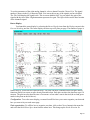
Configuring Mex. . . . . . . . . . . . . . . . . . . . . . . . . . . . . . . . . . . . . . . . . . . . 324
Settings . . . . . . . . . . . . . . . . . . . . . . . . . . . . . . . . . . . . . . . . . . . . . . . . . . . . . . . . 325
Toolbar . . . . . . . . . . . . . . . . . . . . . . . . . . . . . . . . . . . . . . . . . . . . . . . . . . . . . . . . 327
Roots . . . . . . . . . . . . . . . . . . . . . . . . . . . . . . . . . . . . . . . . . . . . . . . . . . . . . . . . . . 328
Running Mex . . . . . . . . . . . . . . . . . . . . . . . . . . . . . . . . . . . . . . . . . . . . . . 329
Displaying Data. . . . . . . . . . . . . . . . . . . . . . . . . . . . . . . . . . . . . . . . . . . . . . . . . . 329
Page ix
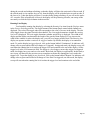
The Oscilloscope Display 329
The Time Amplitude Display 331
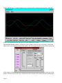
The Cluster Display 333
Combining Time Amplitude and Cluster Classification 335
The Waveform Display 335
Recording From Multiple Electrodes 336
The Signals Display 336
Saving Data . . . . . . . . . . . . . . . . . . . . . . . . . . . . . . . . . . . . . . . . . . . . . . . . . . . . . 337
Interfacing with Experimental Control 337
Waveform Data 338
Antidromic Data 338
Page x
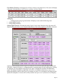
Rex At a Glance...
Data Acquisition
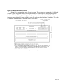
Rex continually acquires samples from the a/d converter and stores the data to a circular memory
buffer. This data is stored to disk when a window is opened. Data is stored until the window is closed.
Each window has an associated pre-time and post-time. These times specify additional data that will be
saved before the window is opened and after the window is closed. Data stored to disk can originate
either from an a/d converter or from global memory variables.
ï a/d sample rate (acquire rate) and disk store rate can be different- e.g. a signal can be sampled at
1000Hz and stored to disk at 250Hz.
ï All rates (acquire rate and store rate) can be independently set on a per signal basis; all signals are
not required to be acquired or stored at the same rate.
ï Maximum a/d sample rate (acquire rate) per channel: 2000Hz.
ï Overall throughput to disk has been tested to at least 16k samples/sec on a 486/33 with SCSI disk.
ï Each signal can be identified with an ascii string that is available to analysis programs.
Data File Format
Rex produces only two types of files: the E-file and the A-file. The E-file contains short fixed
records that identify epochs or times of occurrence. The A-file is composed of variable length data
records. The E-file indexes the A-file. Both files include additional information (such as sequence
numbers and magic numbers) that can be used to verify file integrity.
Laboratory Control
Rex includes a state-set interpreter and language, Spot, for laboratory control. Applications are
programmed using Spot and associated C functions (termed actions) that are called from the state-sets.
Users can also write custom actions in C. The state-set interpreter supports multiple, independent state
chains. Timing resolution for the interpreter is 1msec.
Rex supports industry standard 'Opto 22' type I/O modules for interfacing with devices in the
laboratory. These modules can interface with DC and AC voltages and provide optical isolation between
the computer and the laboratory.
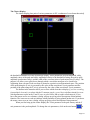
Displays
Rex includes three displays. The running-line display is an oscilloscope simulation. The window
display is an X-Y display suitable for showing eye position and eye position windows. The raster
display shows on-line rasters and spike density functions. This display is completely user customizes in
terms of number of rasters, histograms displayed, size, position, triggers, etc.
User Interface
Users interact with Rex via a graphical interface consisting of pull-down menus, dialogs, and
toggle buttons. Variables and parameters in Rex are contained in structures. The contents of all
structures can be saved in ascii to a file (termed a root file).
Page 1
PC to PC Communication
Rex provides two methods for PC to PC communication. The first system, pcmsg, is suitable for
real-time. 'pcmsg' requires two interface boards that include the Intel 8255 parallel interface chip
(commonly found on digital I/O boards). 'pcmsg' is designed so that the two boards can be cabled
together directly, pin for pin, without any external glue logic. 'pcmsg' provides an eight bit
communications channel between the PCs. This channel is full-duplex- information can travel in both
ways simultaneously. The handshaking protocol is designed to be independent of timing differences
between the PCs. The programming interface presents a messaging model- messages are packaged and
sent between the machines. Messages include checksum. The second method of communication is to use
Ethernet with TCP/IP sockets.
Multi-Unit Sorters
Rex communicates with the Mex multi-unit sorter program via parallel interface using one 8255
parallel chip. Rex will also communicate with the Spectrum Scientific MNAP system using countertimer boards. Each board will accept up to 20 units from the MNAP system. In order to accept more
units, the Rex PC must have available slots for more counter timer boards.
Rex Structure and Operating System Environment
Rex is composed of multiple cooperating processes. For example, keyboard commands, writing
to disk, raster display, data acquisition are all handled by different processes. This architecture,
originally designed to run on Unix, is not easily ported to DOS. Therefore the QNX real-time operating
system was chosen to support Rex on the PC. QNX provides a Unix foundation in a real-time context
with fast interrupt response and disk I/O.
Availability
Rex is available free of charge via executing a short license agreement (the purpose of this
agreement is to preserve the government's rights to Rex and restrict re-distribution). The Rex manual
and a copy of the agreement can be obtained via anonymous ftp from lsr.nei.nih.gov.
Page 2
REX: A Unix-Based Multiple-Process System for Real-Time Data
Acquisition and Control
A.V. Hays, Jr. B.J. Richmond L.M. Optican J.W. McClurkin
National Eye Institute, National Institute of Mental Health, 9000 Rockville Pike, Bethesda, MD., 20892
Introduction
Rex (Real-time EXperimentation) is a real-time system that utilizes a multiple process structure
to divide its functions among various cooperating processes. A running Rex system includes the
procSwitch process to control process interaction, the scribe process to write data on disk, an int process
to respond to interrupts from clocks, analog-to-digital converters, etc., a running line process that
functions as a digital oscilloscope, an window process to display analog data in an X-Y coordinate
system, and a raster process to generate on-line displays of unit activity. A Rex system is not limited to
these processes and may include others. This modular architecture is flexible and easy to maintain.
Various applications may use the same procSwitch and scribe processes but different int, running line,
window or raster processes. The boundaries imposed by distributing Rex among multiple processes
afford some protection against code becoming excessively intertwined and difficult to modify. Rex is
written in C, a structured high level language.
Laboratory control is accomplished with a state-based interpreter in the int process. A state set
description language is translated into tables which drive the interpreter. Rex stores sampled analog data
in rotating buffers in a common memory area shared by all processes. Inter process communication
messages are also passed through this area. Rex produces only two types of data files. One stores
information characterized by epochs and contains long integer times of occurrence, the other stores
variable length records such as analog data or experimental parameters. The epoch file indexes the data
file. Both files contain additional information inserted by scribe that can be used to verify their integrity
or aid in their reconstruction in case of partial loss or corruption.
The original version of Rex ran on the pdp11 using a V6/V7 Unix kernel that was modified to
support real-time applications. The PC version of Rex currently runs with the Photon Window Manager
on the QNX operating system, a POSIX compliant real-time system.
Rex Structure
Rex is designed for an environment composed of multiple laboratories, each equipped with PCs.
These computers are devoted entirely to the on-line tasks in each laboratory. In addition larger machines
may exist for off-line tasks such as data analysis, data archiving, program development, etc.
Previous Design Approach
In a previous approach to developing software for this environment a single large program
performed all the functions of data acquisition, control, and display generation. To conserve space the
machines ran under a small operating system with real-time capability, RT-11. Coding was done in
assembly language for efficiency and access to hardware registers. As more laboratories with different
needs used this program, it became larger and more complex. Modularity broke down as different
programmers modified it. This single program was difficult to debug, maintain, and modify. Capabilities
not needed in one experiment were removed when memory space was critical, and other capabilities
Page 3
were added. A feature of one version was often difficult to transfer to another because of buried
differences.
Debugging problems were more difficult since the operating system did not run the program
under the protection of memory management. Stacks could overflow without being caught and the
operating system itself could be corrupted.
New Approach
The multiple-process structure of Rex solves many of these problems. With inexpensive solid
state memories the laboratory computers can be configured with enough memory to run a larger and
more sophisticated operating system such as Unix. A process in Unix consists of a program memory
image, register values, status of open files, etc. Unix is a timesharing system and schedules run time
among processes that reside in memory or are swapped out to secondary storage. Processes are executed
under the full protection of memory management; stack faults are caught, a process has access only to its
own address space, and execution of sensitive instructions such as halt or reset is prohibited. Each
process interacts with other processes only through inter process communication protocols.
The major functions of Rex exist as individual Unix processes. The boundaries thus imposed
enforce some degree of modularity in Rex. Of course any process can still be poorly constructed
internally. However, there is a ì firewallî between it and the rest of the system. Its interactions are better
defined than if it were a section or overlay in a single large program, sharing the same address space and
registers.
The multiple-process structure facilitates maintenance and the development of new functions.
Rex systems may run different processes for various applications yet still include the same processes for
functions such as keyboard handling and file writing. When changes are made to processes each Rex
system needs only to run the new versions to be updated. When debugging, each process has its own
address space and can be traced separately. Multiple processes also provide a way for large systems to
effectively utilize the full memory capacity of machines such as the pdp11, which have a larger physical
memory space than virtual address space. For example, the pdp11/73 has a memory capacity of 4MB
and a virtual address space of 64KB text, 64KB data.
Rex is written in C, a structured high level language. C has separate compilation, provides full
access to hardware, and is very efficient. C is easily interfaced to assembly language.
Rex Processes
A typical Rex system is composed of five or more processes. The most common processes are
described below.
Data
The data process is a null process that declares the common in core data area and launches the
procSwitch process. It is executed before other Rex processes and remains in memory at all times. Since
the data process is the first process executed it is named Rex.
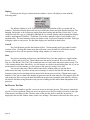
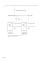
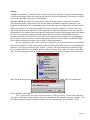
ProcSwitch
The procSwitch process supervises the launching of all other processes and the opening and
closing of files. ProcSwitch displays a small tool bar containing pull-down menus and toggle buttons
that provide user input. ProcSwitch maintains a table of all currently established Rex processes and their
status.
Page 4
Scribe
The scribe process writes and maintains data files on disk. When a Rex process desires that data
be saved on disk it sends a message to scribe telling it what the data is and where it is located. It is
scribe's responsibility to write the data into the proper file in the correct format. For example, the int
process might sample data from an analog-to-digital converter and store it in a rotating buffer. When a
high water mark is reached it sends a message to scribe to write the data to disk.
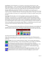
Int
Every experiment is unique, and hence some part of Rex must be easily adaptable to the
investigator's needs. This is accomplished in Rex by devoting one process, int, to the experimentspecific code. The experiments currently running under Rex investigate the neurophysiology of the
visual and eye movement systems. Stimuli are presented to subjects according to a behavioral paradigm.
Analog signals are digitized and events (such as pressing a bar or the firing of cells in the brain) are
recorded by the computer. Since the control of the experiment and the collection of the data are
dependent on the behavior of the subject in these applications, a great deal of digital signal processing
must be done in real-time by Rex (e.g., the onset of a rapid eye movement is detected by a digital filter).
In its present configuration Rex is interrupt driven from the real-time clock, which normally
interrupts at a one kilohertz rate. (Other applications may have higher sampling rates when less
processing is required.) The int process is divided into two parts, an upper-level one that handles the
communication with the other Rex processes and the operator, and a lower-level one that responds to the
interrupts. The upper-level part displays a tool bar containing pull-down menus and toggle buttons to
handle user input. When a new int process is launched, its tool bar appears adjacent to the procSwitch
tool bar. The lower-level subroutine is divided into functionally discrete sections, making it simple to
modify. Rex provides a method for users to easily create new int processes (see next section). During an
experiment many int processes may be executed by Rex; the experimental paradigm can be changed
quickly by switching to a different int process.
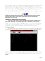
Running Line Display
The running line display process provides the functions of a digital oscilloscope. It can display
analog data, neuronal units, and a timing bar. The time base of the display varies from 30 Hz to 1000
Hz. It has free running and triggered modes. In triggered mode, it has repeat and one-shot modes. Rex
supports multiple running displays.
Window Display
The window display process provides an X-Y display of analog data. It has immediate and
storage modes. In storage mode, the screen refresh rate can be set to any interval between 16 and 1024
milliseconds, or the screen refresh can be triggered. In triggered storage mode, users can vary the
number of draws between refresh cycles. Rex supports multiple window displays
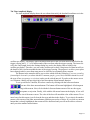
Raster Display
The raster display provides T-Y plots of unit data. The data are grouped according to
experimental condition for each plot. Unit data can be displayed as spike rasters or as spike density
functions. The raster display can have multiple pages, each containing up to 64 plots. Data from up to 10
different units can be display in each plot. Rex supports multiple raster displays.
Page 5
Laboratory Control
To achieve useful control in the laboratory, timing and sequencing of events in real-time must
occur precisely and efficiently. State notation is a powerful tool for accomplishing this control. The
advantage of state notation is that it is simple and easy to learn, yet able to implement even the most
complex control sequences. The process of reducing a control problem to state notation often helps
clarify the problem and identify logical errors. Rex incorporates a state set processor for laboratory
control. This processor is a part of the int process; it is executed on interrupt from the clock, currently
every millisecond.
State Concepts
State notation as implemented in Rex includes the following elements. A state is the current
condition or stage of a control sequence. A state consists of the specification of a function to occur when
the state is entered (actions) and the conditions that must be met for transition to occur to another state
(escapes). Escapes to other states can happen in the following ways:
ï Countdown of a timer to zero.
ï Bit pattern set in a flag word.
ï Bit pattern not set in a flag word.
ï True return from a function call.
ï Variable equal to a constant.
ï Variable less than a constant.
ï Variable greater than a constant.
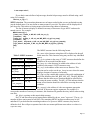
Each state contains a long integer (32 bits) to specify the time for escapes on timer countdown
(an integer random factor can also be specified). Upon entering a state this long time is loaded into a
counter which is then decremented each interrupt. States may contain multiple escapes of mixed types.
Each escape is evaluated in turn at interrupt time; transition occurs on the first escape found true.
The Rex state processor is small and designed for fast execution. It uses a linked list to
efficiently test escapes. State actions are not performed directly, but are accomplished by calls to
functions. The action is therefore the address of a function that is called by the state processor when the
state is entered. Up to ten arguments can be passed to the function. The arguments can be constants of
type long or pointers to global variables. Many standard actions are available in a system library, or
users may write their own. An example of a commonly used action is dio_on(BIT). This action sets a bit
(specified by the device id BIT) in the digital output interface word without disturbing other bits already
set.
A provision is made to store a record of state transitions and the time of the transition on disk.
This is done by specifying an integer event code contained either in the state or returned by an action.
When a state transition occurs this code is entered into the event buffer. If the action for that state returns
an event code it overrides the one stored in the state and is entered instead. A state in Rex, therefore, is
composed of:
ï Event code.
ï Action (function address) and up to ten long integer or global variable pointer arguments.
ï Long time to initialize timer for timed escapes.
ï Integer random factor for time.
ï Escapes.
Page 6
State Set Specification Language
A user specifies state sets by writing in a language called Spot (State PrOcessor Translator). The
Spot compiler translates the language into the tables that drive the state processor. The Spot compiler is
implemented with the compiler writing tools of Unix: Lex and Yacc. Spot source files are divided into
two sections. The first section contains C source code and is passed through Spot untouched to the C
compiler. Functions for actions are placed in this section. The second section is the state set
specification.
The Spot source file is the primary user interface to the Rex system. Contained in the file is the
complete laboratory control specification for an experiment including the source for any specialized
actions not found in the system library. Usually, when modifying or creating new Rex applications, the
user will only have to be concerned with this one file. To further simplify the user interface the
generation of the Rex int process (as well as all Rex processes) is under the control of make, a Unix
utility. After the user edits the Spot source file he simply types the command make sf=spotname where
spotname is the name of the Spot source file. This utility then performs all necessary compilations
(including Spot), library searching, and loading, and yields a new int process.
Runtime Considerations
At runtime the state set processor begins execution when the real-time clock is started. Some of
the variables contained in a state can be changed at runtime. A special pull-down menu, accessed from
the int tool bar, exists to do this. The changeable variables are arguments to actions, times, and the event
code.
Shared Data Structures
The data process sets up a data space that is shared by all of the processes. A process adjusts its
memory map to reference the shared space. This space contains the data buffers and the inter process
communication area.
When an interrupt occurs, the int process may collect data. This data need not be saved on the
disk, but must be available for on-line display by other processes. Int keeps this data in two buffers in
the shared space. Data that can be described as an epoch (e.g., a single-unit's action potential, or when
the subject presses a bar) are stored in the event buffer. Any data that can not be described as an epoch
(e.g., eye position or target position) are stored in the analog buffer. The internal structures of the event
and analog buffers are different, and when the data are saved on the disk, two separate files are used (see
below).
Event Buffer
All event data can be identified by only two numbers: an event code and a time of occurrence.
The int process records epochs by entering them into a circular event buffer. If events are being saved,
scribe writes the data to the disk whenever a high water mark is reached. The circular buffer is large
enough to make many events available to the running line, window, and raster display processes. During
a neurophysiological experiment, the most common event is the single-unit action potential, or spike.
These can occur with average firing rates as low as 1 per second, or as high as 1000 per second. It is
essential that some representation of them be available on-line. The raster display process provides an
on-line version of the standard unit raster, built out of the incore event buffer.
Page 7
Analog Buffer
During the experiments run with Rex many analog signals must be sampled and saved.
Collection of analog data is greatly complicated by several factors. For example, the time from which to
begin saving may precede the actual time when recognition of the need to save occurs, e.g., one may
wish to save eye position from 100 milliseconds. before the beginning of an eye movement. Also, the
number of samples collected during the run may be greater than the storage capacity of the disk. The
approach taken in Rex is to collect the data continuously in rotating buffers, and only store data
according to requests in the state set.
A very large buffer is used to hold the analog samples, and when the buffer is full, the load
pointer wraps around to the beginning of the buffer. The user controls the saving of this data on the disk
with actions in the state set. These actions control the opening, closing and canceling of a data keeping
window. Scribe keeps all data collected from the time the window is opened until the window closes, no
matter how many times the buffer wraps around (within the limits of the computer's capacity). If a high
water mark is hit, scribe writes out a partial data record marked with a continuation flag.
The user also specifies the number of samples to be kept before the window is opened, and the
number of samples to be kept after the window is closed. The user need only be concerned with opening
and closing the data keeping window. The Rex system performs the bookkeeping necessary to store the
data on disk. In addition, every time an analog record is written out an event is generated that indexes
the analog record (see below).
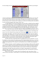
Menu System
Rex provides a menu system that allows variables to be accessed and changed at run time.
Variables have different types including char, string, octal, decimal, etc. A function can be created to be
called when a menu or menu variable is accessed. This function may be called before access, after
access, or both. This function can affect how the variable is accessed. For example, the function might
prohibit a variable from being changed if the new value is not legal, or perform necessary initialization
when a variable is set to a new value.
Data File Formats
Rex data is stored in two files. The E-file contains data which can be described as epochs. The
A-file contains all other data, including information about the experimental run that created the data. The
E-file also indexes the A-file. Both files contain redundant information so that a complete loss of either
file does not preclude access to the other file, and that partial losses from one file can be bridged over.
The E-file has a fixed record length structure, while the A-file has a variable record length structure.
Both files begin with a one block header. The Unix system dynamically allocates file space; predetermination of file length is unnecessary.
Rex Header Block
A 512 byte header block is written for both files when they are created. The first word of the
header block is a size, in bytes. In the E-file this is the size of the fixed record length, in the A-file it is
the size of a fixed-length header associated with each variable length record. The next item in the header
block is the file name used to create the files. Then follows the version number for the Rex system that
created the file. These two items are stored as null-terminated ASCII strings, making them readable
without a special program. The rest of the header block is available for other information.
Page 8
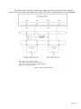
E-file Format
After the header block, the E-file consists of an arbitrary number of records, each four words
long. The structure of each record is identical. The first word is a sequence number added by the scribe
process. The second word is the event code for this record. If the code is a positive number, it
corresponds to an event that occurred at a time which is stored in the next two words as a long integer.
(Time is kept as clock ticks, and the clock rate is kept in a standard header stored in the A-file.) If the
code is negative, the record is an index to a variable length record in the A-file; the next two words form
a long integer that is the offset in bytes from the beginning of the A-file to the record header.
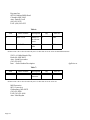
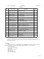
A-file Format
After the header block the A-file consists of an arbitrary number of variable length records.
Every record is written in the same format: a ten word analog header followed by an arbitrary length
data field. The structure of the analog header is the same for every record. The first two words are a long
integer magic number. The third word is an unsigned ordinal sequence number assigned by the scribe
process. The fourth word is the event code for this record (the same as the event code in the E-file record
which indexes this A-file record). The next two words form a long integer containing the time of
occurrence of the epoch associated with this record. The following two words form a long integer
available to the user. The next word is an integer used to mark continuation records. The last word is the
length (in bytes) of the following data field.
Since Rex collects data in rotating buffers, it is possible to store arbitrarily long streams of data.
For practical reasons this stream is broken up into short data records that are stored on the disk. When
the data buffer pointer exceeds a high water mark, the scribe process writes a partial data record into the
A-file. Subsequent pieces of the data stream are then written as continuation records. Each continuation
record has the same format as all other A-file records, except for non-zero continuation words in the
headers.
Data File Consistency
The Rex file formats incorporate redundant information to allow the consistency of files to be
checked, and some effort to be made at restoring damaged files. Since data is often transferred from disk
to disk, or from disk to tape and back again, it is necessary to check that blocks have not been lost or
scrambled. Both files are consistent if their sequence numbers are correct and if the analog records in the
A-file are correctly indexed by the E-file. If the E-file becomes corrupted, it is easily re synchronized by
searching for a block boundary, since the event record size evenly divides the physical block size. If the
A-file becomes corrupted, it may be re synchronized by searching for the magic number. This number
(1210832817L) is four bytes long, chosen to be unique by word or byte search, and outside the range of
12 bit analog-to-digital converters. The amount of data missing can be determined from the gap in the
sequence numbers. A utility program exists (\f3srdd\f1) which checks the data files and verifies their
consistency.
Data File Portability
Problems may arise when data files are moved to other computers. In general, data is not
portable across machine architectures. Differences may involve word size (e.g. 16 bits on pdp11, 32 bits
on VAX), byte ordering within words, and bit ordering (whether least significant bit is to left or right).
Because of alignment differences a structure used in a C program to access a data file on one machine
may not access the same fields properly on another machine.
Page 9
One solution to this problem is to add to analysis programs multiple ways of accessing data files
and multiple formats for each machine. A much simpler solution, however, is to instead change the data
file for each machine. This permits a uniform access method and single data file structure for all
architectures. With this solution porting analysis programs to new machines does not require new data
formats or changes to access methods. A utility program exists to convert the Rex data files to a new
format. The identification of the current format of the data file is stored in the data file header block.
Information is not lost during conversion- given the current format a data file can be again converted to
any other format.
Discussion
The prototype version of Rex was completed in March of 1981, and ran on the pdp11 processor.
The PC port of Rex was completed in Spring of 1992. Rex comprises about 8000 lines of C code
(comments not included).
Rex takes advantage of many Unix features to provide a real-time laboratory system that is easy
to use. The Spot language and the make utility allow the user to easily create new Rex modules to meet
his experimental needs. Hence the investigator has more time to spend on the design of the experiment
and the analysis of the data.
References
Unix is a trademark of the Bell Telephone Laboratories. RT-11, pdp11, and DEC are trademarks
of Digital Equipment Corporation. QNX is a trademark of Quantum Software Systems, Ltd., 175
Terrence Matthews Crescent, Kanata, Ontario K2M 1W8, (613) 591-0931.
Ritchie, D.M. and Thompson, K., "The Unix Timesharing System," Bell System Technical
Journal, Vol. 57 (1978), pp. 1905-1929.
Kernighan, B.W. and Ritchie, D.M., The C Programming Language, Prentice-Hall, New Jersey,
1978. Snapper, A.G. and Inglis, G.B., "SKED Software System, Manual 3 Rev. D," State Systems, Inc.,
Kalamazoo, MI.
Lesk, M.E. and Schmidt, E., "Lex - A Lexical Analyzer Generator," Unix Programmer's Manual,
Seventh Edition (1979), Bell Telephone Laboratories, New Jersey. Johnson, S.C.,
"Yacc: Yet Another Compiler-Compiler," ibid. Feldman, S.I., "Make - A program for
Maintaining Computer Programs," ibid.
Page 10
SPOT: State Process Translator for REX
Barry J. Richmond Arthur V. Hays Lance M. Optican John W. McClurkin
Introduction
The REX real-time laboratory control and data acquisition system has been designed so control
paradigms for specific experiments can be flexibly implemented. During implementation the user's
attention is largely directed to features that are unique for the experiment being designed. This end is
realized through implementation of a translator for a state-set based control specification language, Spot
(State PrOcessor Translator). The Spot translator produces tables that are compiled by the C compiler.
These tables contain specifications that define states; associated with each state are conditions, escapes,
that govern transitions to other states. When a new state is entered a user written subroutine (termed an
action) can be called if its name is included in the specification of the new state. Virtually no restrictions
are placed upon the action. It may touch hardware, do calculations and set flags for later use, process
lists of stimuli, etc. The Spot translator makes the chain of states extremely easy to specify and edit.
Multiple, independent state chains are permitted and executed in parallel.
Process Control
REX process control is implemented using a logical structure which depends upon states,
actions, and escapes. This system is table driven, executed by an interpreter that runs every millisecond.
The tables are difficult to construct by hand, so a translatable language, Spot, has been implemented to
make the creation of the tables transparent to the user.
Control routines are always in a current state. When an appropriate condition, recognized in
either hardware or software, occurs, a transition or escape to another state takes place. When a new state
is entered after an escape has occurred two useful things happen. First, a function called an action, may
be called. Actions are usually written in the C language, and must be compatible with C calling
conventions. The action may be passed up to sixteen arguments. These arguments can be either long
integers or pointers to variables. Second, an event code composed of an integer number and a long
integer time-of-occurrence can be placed into the event buffer. The user selects the event code. Standard
event codes generally come from some #include file, while specific codes for the particular experiment
may be placed directly in the paradigm specification. If the user wishes, a code may be returned by the
action which will placed in the event buffer instead. For example, if the action was setting some
variables from a table, it might return a code that indicates which table entry was selected.
A state also contains the variables time (a long integer), and random (a short integer). When a
state is entered, a countdown timer is initialized to the time variable (if it is non-negative) plus a portion
of the random variable. The random variable is divided into quarters, with 0, 1/4, 1/2, 3/4, or the whole
added to the timer. Note if the time variable is negative, the countdown timer is not re-initialized when
the state is entered.
Spot Language Specification
Spot file sections
The Spot translator takes as input a specification file (termed a spot file) with suffix ".d". Each
Spot specification file is divided into two sections separated by the delimiter "%%". The first section is
Page 11
composed of include files, actions and other pre-initialized subroutines, user defined menus, user
defined functions, and user defined real time variables. Actions may also be placed in user libraries;
however, placing actions specific to individual paradigms in the paradigm's Spot file is usually much
more convenient. Between the first and second sections a "%%" delimiter is placed. The second section
contains the Spot state set specification for the paradigm. The state set chains of the paradigm are
declared here. The Spot translator produces a C source file, with the suffix ".d.c" appended to the Spot
file name.
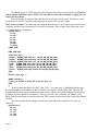
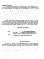
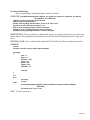
Include files
The following headers are included automatically in the C source produced by Spot.
#include <stdio.h>
#include <sys/types.h>
#include "../hdr/sys.h"
#include "../hdr/cnf.h"
#include "../hdr/proc.h"
#include "../hdr/buf.h"
#include "../hdr/menu.h"
#include "../hdr/state.h"
#include "../hdr/ecode.h"
#include "../hdr/device.h"
#include "../hdr/cdsp.h"
#include "../hdr/idsp.h"
#include "../hdr/int.h"
Since these headers are automatically added by Spot they should not be included again in the
".d" Spot file.
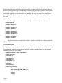
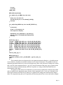
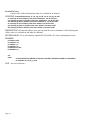
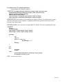
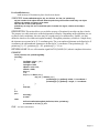
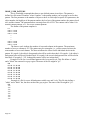
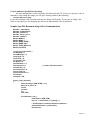
User defined actions
Rex includes a library of actions that can be called from states, but this library will probably not
be sufficient to build a complete experimental paradigm. In particular, if users want to present a number
of conditions in a random sequence they will need to write an action that selects the experimental
condition for each trial. For example:
#include "memSac.h" /* table of conditions */
/* global variables */
int mfTargX = 0;
int mfTargY = 0;
int antiTargX = 0;
int antiTargY = 0;
int trialCounter = -1;
int totalTrials = 0;
int currstim;
int blockcount = 0;
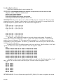
int pick_targ_location()
{
static int ptrlst[2 * NUM_STIM] = { 0 };
static int rs_shift = 10;
int targx;
int targy;
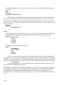
Page 12
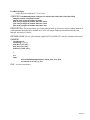
/* build list of conditions */
if(--trialCounter <= 0) {
trialCounter = NUM_STIM;
for(i = 0; i < trialCounter; i++) ptrlst[i] = i;
shuffle(trialCounter, rs_shift, ptrlst);
blockcount++;
}
currstim = ptrlst[trialCounter - 1];
totalTrials++;
memSacTrialList[currstim].total++;
/* set the time of the target-fixation point gap state */
set_times("gap", memSacList[currstim].delay, -1);
/* set the location of the target window */
switch(memSacList[currstim].direction) {
case 1:
/* target in movement field */
targx = mfTargX;
targy = mfTargY;
break;
case -1:
/* target opposite movement field */
targx = antiTargX;
targy = antiTargY;
break;
}
/* action to set eye window position */
wd_pos(WIND1, targx, targy);
/* return code to enter into E file */
return(memSacList[currstim].ecode);
}
Beginning with Rex 7.2, actions can have up to 10 arguments. The arguments can be either type
long constants, or pointers to global variables.
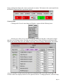
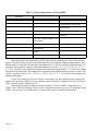
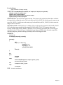
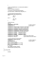
User defined menus
You may build menus to allow modification of variables at run time. The menus are accessed
from a dialog launched from the int process tool bar. Prior to version 7.0, Rex allowed user menus to
access submenus. Submenus are no longer supported because they are no longer needed.
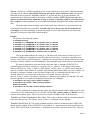
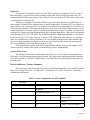
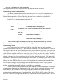
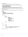
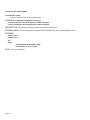
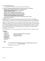
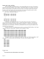
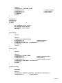
Default Menu. Spot will build one menu automatically. This menu is named state_vars. All that is
needed for this menu is a list of variables to display. The list of variables is defined in an array of
structures of type VLIST and must be named state_vl. For example:
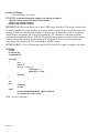
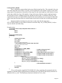
VLIST state_vl[] = {
{"clear_all_da", &clear_all, NP, clearVaf, ME_AFT, ME_DEC},
{"do_two_ramps", &do_two_ramps, NP, NP, 0, ME_DEC},
{"ramp0_xda", &r0_xda, NP, NP, 0, ME_DEC},
{"ramp0_yda", &r0_yda, NP, NP, 0, ME_DEC},
{"ramp1_xda", &r1_xda, NP, NP, 0, ME_DEC},
{"ramp1_yda", &r1_yda, NP, NP, 0, ME_DEC},
{"fix_xwind", &fxwd, NP, NP, 0, ME_DEC},
Page 13
{"fix_ywind", &fywd, NP, NP, 0, ME_DEC},
{"fix_oxwind", &foxwd, NP, NP, 0, ME_DEC},
{"fix_oywind", &foywd, NP, NP, 0, ME_DEC},
{"user_msg",
&tst_user, NP, NP, 0, ME_DEC,}
{"single_trace", &tst_single, NP, singleVaf, ME_AFT, ME_DEC},
{NS},
};
The VLIST structure has the following format:
Vl_name is the character string that will identify the variable in the
Table 1: VLIST Structure
menu. This character string may not have any imbedded spaces.
Vl_add is the address of the variable itself. This variable must be a
Member name Example
global.
Vl_basep is an amount that may be added to the variable pointer. For
char *vl_name clear_all_
simple global variables, vl_basep should be NP (null pointer). If vl_add
da
is a pointer to the first element of an array, vl_basep might be the offset
void *vl_add
&clear_al
into the array for this variable.
l
Vl_accf() is the address of a function to be called when the variable is
changed. Variable access functions are useful for checking the range of
void
NP
a variable or doing some type of initialization. If you do not need a
*vl_basep
variable access function, the vl_accf() member of the structure should
be NP.
int
clearVaf
Vl_flag is a flag variable that consist of the oríed combination of any of
(*vl_accf)()
the following bits: ME_BEF, ME_AFT, ME_LB, ME_ILB, ME_GB,
char vl_flag
ME_AFT
ME_IGB. The ME_BEF bit indicates that the variable access function
vl_accf() should be called before changing the value of the menu
char vl_type
ME_DEC
variable. The ME_AFT bit indicates that the variable access function
should be called after changing the value of the menu variable. The
ME_LB bit indicates that the value of vl_basep should be added directly to vl_add. The ME_ILB bit
indicates that vl_basep is the address of the value that should be added to vl_add. The ME_GB bit
indicates that the menu contains a global pointer (me_basep) that must be added to vl_add. The
ME_IGB bit indicates that the menu global pointer is the address of the value that must be added to
vl_add.
Vl_type is a flag that indicates the variable type. Valid types are ME_ACHAR, ME_OCT,
ME_DEC, ME_HEX, ME_LOCT, ME_LDEC, ME_LHEX, and ME_STR. Me_achar indicates that the
variable is a single ascii character. Me_oct indicates that the variable is on octal value. Me_dec indicates
that the variable is a decimal value. Me_hex indicates that the variable is a hexidecimal value. Me_loct
indicates that the variable is a long octal value. Me_ldec indicates that the variable is a long decimal
value. Me_lhex indicates that the variable is a long hexidecimal value. Me_str indicates that the variable
is a string.
The last entry in any VLIST structure array must be NS, on a line by itself. NS stands for "null
string", and marks the end of the variable list. Note, failure to end the VLIST definition with an NS line
will cause REX to crash when it attempts to display the menu.
If you only use the default state_vars menu, then you must also define a help message. The name
of the help message must be "hm_sv_vl". For example:
char hm_sv_vl[] = "\
do_two_ramps-\n\
0: one ramp active\n\
Page 14
1: two ramps active";
If you donít want to define a help message, then the help message must be defined using a null
string. For example:
char hm_sv_vl[] = "";
MENU structure. The reason that submenus are no longer needed is that you are not limited to using
just the default menu. You may define as many menus as you wish. The menus will be displayed in a
pull down list. This makes accessing menus easier than using chains of submenus.
The list of menus to display is defined in an array of structures of type MENU and must be
named umenus. For example:
MENU umenus[] = {
{"state_vars", &state_vl, NP, NP, 0, NP, hm_sv_vl},
{"separator", NP},
{"ramp_list", &ramp_vl, NP, ral_maf, ME_BEF, ral_agf, hm_ramp},
{"separator", NP},
{"eye_winds", &eyewnds_vl, NP, ral_maf, ME_BEF, ral_agf, hm_eyewnds},
{"eye_offsets", &eyeoffs_vl, NP, ral_maf, ME_BEF, ral_agf, hm_eyeoffs},
{NS},
};
The MENU structure has the following format:
Me_name is the character string that will be displayed in the pull
Table 2: MENU structure
down menu list. This character string may not have any imbedded
spaces.
Member Name
Example
Me_vlp is a pointer to the array of VLIST structures that define the
variables to be accessed from this menu.
char * me_name ramp_list
Me_basep is a value that may be added to the address of each
variable in this menuís VLIST structures array.
VLIST *me_vlp &ramp_vl
Me_accf() is the address of the menu access function. This
unsigned
NP
function can be used to set the me_basep in cases where the menu
me_basep
displays elements of an array of structures.
Me_flag is a flag variable that consists of the oríed combination of
int (*me_accf)() ral_maf
any of the following bits: ME_BEF, ME_AFT. The ME_BEF bit
int me_flag
ME_BEF
indicates that the menu access function should be called before
accessing the menu variables. The ME_AFT bit indicates that the
int
ral_afg
menu access function should be called after accessing the menu
(*me_rtagen)()
variables.
char *me_help
hm_ramp
Me_rtagen() is the address of a the root argument generation
function. If the menu requires arguments, for example if it
accesses the members of an array of structures, this function will generate the array indices when writing
root files.
Me_help is a pointer to this menuís help message.
Rex 7.0 and later allow special menu entries marked by the me_name "separator". The me_vlp
member of these entries must be null (NP). The remaining MENU structure members may be left
undefined. If you do define the remaining members of a separator MENU structure, they must be
defined to be 0. Rex will put a separator line in the user menus pull down menu where ever there is a
separator entry.
Page 15
As with the arrays of VLIST structures, the last entry in the umenus array must be NS. Failure to
end the umenus definition with an NS line will cause Rex to crash when it attempts to display the user
menus pull down menu.
Rex will display the menus in the order they are listed in the umenus array. This allows you to
group menus as you like, separating logical groups of menus with separator entries.
More menu examples. The following code snippets illustrate how to use menus to access members of
a structure and how to access members of an array of structures. This example shows the menu access
for a single instance of a structure.
typedef struct {
int len;
int ang;
int vel;
int xoff;
int yoff;
int type;
int ecode;
} RMP_PAR;
RMP_PAR ramp;
VLIST ramp_vl[] = {
{"length", &((RMP_PAR *)NP)->len, NP, NP, ME_GB, ME_DEC},
{"angle", &((RMP_PAR *)NP)->ang, NP, NP, ME_GB, ME_DEC},
{"velocity", &((RMP_PAR *)NP)->vel, NP, NP, ME_GB, ME_DEC},
{"xoff", &((RMP_PAR *)NP)->xoff, NP, NP, ME_GB, ME_DEC},
{"yoff", &((RMP_PAR *)NP)->yoff, NP, NP, ME_GB, ME_DEC},
{"type", &((RMP_PAR *)NP)->type, NP, NP, ME_GB, ME_DEC},
{"ecode", &((RMP_PAR *)NP)->ecode, NP, NP, ME_GB, ME_DEC},
{NS},
};
char hm_ramp_vl[] = "";
MENU umenus[] = {
{"ramp_par", &ramp_vl, &ramp, NP, 0, NP, hm_ramp_vl},
{NS},
};
In this example the phrase &((RMP_PAR *)NP)->len in the ramp_vl definition indicates that
this variable address is the address of the len member of a structure of type RMP_PAR. The ME_BG
notation indicates that a menu global base pointer must be added to this variable address. In the umenus
definition, the menu global base pointer me_basep is given the value of &ramp, the instance of the
RMP_PAR structure being accessed by this menu. This example assumes that ramp is a globally defined
variable.
The next example shows a snippet of code for a menu that access members of an array of
structures.
typedef struct {
int len;
int ang;
int vel;
int xoff;
int yoff;
Page 16
int type;
int ecode;
} RMP_PAR;
RMP_PAR rampList[16];
int r_agf(int call_cnt, MENU *mp, char *astr)
{
if(call_cnt >= 16) *astr= '\0';
else itoa_RL(call_cnt, 'd', astr, &astr[P_ISLEN]);
return(0);
}
int r_maf(int flag, MENU *mp, char *astr, ME_RECUR *rp)
{
int rampnum;
if(*astr == '\0') rampnum = 0;
else rampnum = atoi(astr);
if((rampnum < 0) || (rampnum >= 16)) return(-1);
mp->me_basep = (unsign)&rampList[rampnum];
return(0);
}
VLIST ramp_vl[] = {
{"length", &((RMP_PAR *)NP)->len, NP, NP, ME_GB, ME_DEC},
{"angle", &((RMP_PAR *)NP)->ang, NP, NP, ME_GB, ME_DEC},
{"velocity", &((RMP_PAR *)NP)->vel, NP, NP, ME_GB, ME_DEC},
{"xoff", &((RMP_PAR *)NP)->xoff, NP, NP, ME_GB, ME_DEC},
{"yoff", &((RMP_PAR *)NP)->yoff, NP, NP, ME_GB, ME_DEC},
{"type", &((RMP_PAR *)NP)->type, NP, NP, ME_GB, ME_DEC},
{"ecode", &((RMP_PAR *)NP)->ecode, NP, NP, ME_GB, ME_DEC},
{NS},
};
char hm_ramp_vl[] = "";
MENU umenus[] = {
{"rampList", &ramp_vl, NP, r_maf, ME_BEF, r_agf, hm_ramp_vl},
{NS},
};
This examples shows two functions, the root argument generation function r_agf and the menu
access function r_maf that are needed for menu access to arrays of structures. The purpose of the root
argument generation function is to convert an integer array index value into an ascii string to be written
into a root file. In the argument list for r_agf, call_cnt is the element of the array, mp is a pointer to the
menu struct (in this case &umenus[0]), and astr is a pointer to a string variable that holds the ascii
representation of the index.
The purpose of the menu access function is to convert an ascii string into an integer array index
and set a pointer to the appropriate array element. In the argument list for r_maf, mp is a pointer to the
menu struct (in this case &umenus[0]) and astr is a pointer to the string to be converted to an integer
index. The arguments flag and rp are required by the function protocol but are not used in this example.
Page 17
In the umenus definition, the value of me_basep is set to null (NP) because me_basep is computed by the
access function.
User defined functions
In Rex, actions are just functions, but they are functions that are called by the state processor and
are only called once when the processor enters a state. Thus, they will only be called when the Rex clock
is running. Rex 7.0 also provides a mechanism for calling functions independently of the state processor.
This mechanism is to list the functions in an array of structures of type USER_FUNC. The name of the
USER_FUNC array must be ufuncs. The functions themselves are ordinary C functions. They should be
of type int or void. The functions may have up to sixteen arguments and the arguments may be of type
int, float, or char *. The functions are called by entering values for their arguments in the user functions
dialog that can be displayed from a pull down menu in the int process tool bar. User defined functions
must be defined, then listed in the ufuncs array. For example:
void f_rampReset(void)
{
( body of function );
return;
}
void f_rampOffset(int Xoff, int Yoff)
{
( body of function );
return;
}
USER_FUNC ufuncs[] = {
{"reset", &f_rampReset, "void"},
{"offset", &f_rampOffset, "%d %d"},
{NS},
};
The USER_FUNC structure has the format: N_name is a
character string that identifies the function in the dialog. This
Table 3: USER_FUNC Structure
string may have imbedded spaces.
N_ptr() is the name of the function that will be called. To get the
Member name
Example
function called, you enter values for the arguments in the
dialogís text widget, then enter a carriage return.
char n_name[]
"offset"
Format is a character string consisting of tokens that are used to
int (*n_ptr)()
f_rampOffset
convert the text you enter in the widget to the values that are
passed to the function. The tokens are separated by a a space.
char format[]
"%d %d"
The meaning of the tokens is the same as in a C printf statement,
i.e."%d" indicates conversion to an integer value, "%f" indicates
conversion to a floating point value, etc. Currently, Rex supports conversion to integer, floating point
and character strings, i.e. "%d %f and %s". You must enter one token for each argument in your
function. This allows Rex to do some error checking. If your function doesnít take any arguments, they
you should set the format string to "void". If you want to write functions that take a variable number of
arguments, leave the format character string blank. This will cause Rex to parse what you enter in the
functionís widget into two character strings. The first will be all of the characters up to the first space.
Page 18
The second will be the rest of the string. Rex will call your function with pointers to these two character
strings. In this case, you must define your function to take two char * arguments, i.e.
void function(char *str1, char *str2)
You will need to add code to your function to parse the two character strings to extract the
arguments.
As with the arrays of VLIST and MENU structures, the last entry in the ufuncs array must be NS.
Failure to end the ufuncs definition with an NS line will cause Rex to crash when it attempts to
display the user functions dialog.
Real time variables
Prior to Rex 7.0, values of variables could only be displayed by bringing up a menu or by typing
a command such as type trials. Once displayed the values were not updated. If you had variables that
tracked the subjectís performance such as percent correct or number of trials completed, you had to
repeatedly bring up the menu or type the command to see the new values for these variables. Rex 7.0
provides a mechanism to continuously display the values of variables. This mechanism is to list the
variables in an array of structures of type RTVAR. The name of the RTVAR array must be rtvars. For
example:
RTVAR rtvars[] = {
{"number of trials", &nTrials},
{"trials remaining", &trialsRemaining},
{"blocks completed", &nBlocks},
{"total trials", &totalTrials},
{"number correct", &correctTrials},
{"percent correct", &percentCorrect},
{NS},
};
The RTVAR structure has the following format: Rt_name
is a character string that identifies the variable in the dialog.
Table 4: RTVAR Structure
This name may have imbedded spaces. Rt_var is the
address of the variable to be displayed. Real time variables
Member Name
Example
must be of type int. You can display up to 64 variables in
the dialog.
char *rt_name
"number of trials"
Rex updates the display with the values of the variables
int *rt_var
&nTrials
every second for as long as the dialog is displayed.
As with the arrays of VLIST, MENU, and USER_FUNC
structures, the last entry in the rtvars array must be NS.
Failure to end the rtvars definition with an NS line will cause Rex to crash when it attempts to display
the real time variables dialog.
Comments
Comments are allowed anywhere, and unlike comments in the C compiler, they may be nested.
They are stripped out of the output file.
State set declaration
The beginning of the state set declaration is marked by the delimiter "%%". Following the "%%"
delimiter, each paradigm must start with the keyword ident or id, followed by the paradigm number
(which is displayed on the screen at run-time). This is not optional and Spot will give an error if it is
Page 19
not included. Optionally, the keyword restart followed by the name of an initialization subroutine
may follow.
%%
id 300
restart rinitf
(declaration of state set chains)
A Spot file may have multiple independent chains of states which are executed asynchronously.
Each of the asynchronous chains must start with a name followed by an open curly brace. The entire
chain must then be terminated by a close curly brace. After the opening curly brace the next statement
must be status or stat, followed by ON or OFF to indicate whether the chain is on or off at start or restart
time. For example:
chainA {
status ON
(state declarations...)
}
States
Each state begins with its name followed by a colon, e.g. fpon:. The initial state in each chain must
be indicated by preceding it with the keyword begin. An example of the first state in a chain:
begin fpon:
code FPONCD
rl +30
time 2000
rand 1000
to stimon
An example of a subsequent state in a chain:
stimon:
code STIMCD
do dio_on(LED2)
rl 50
time 500
to stimoff
If there is an event code to be put into the event buffer when the state is entered, it must be next.
The event code is specified using keyword code, for example code 1101 or code FPONCD. Beginning
with Rex7.2, you can specify the event code with a pointer to a global variable as well as with a constant
value. This allows you to drop trial specific event codes with out having to call an action. For example:
code &trialCode
Actions, running line levels, and times follow in any order with the following restriction: time
and random must be adjoining in either order.
Running line. The running line is used both to indicate state transitions in the running line display and
to trigger the running line and eye window displays. The running line level is displayed on the REX
moving display as a continuous line at different positions on the screen. Its keyword specifier is rl.
Running line levels are absolute when not preceded by a + or -, and relative when they are preceded by a
+ or -.
Page 20
Actions. Actions are C-callable subroutines. One action is allowed per state, and is called immediately
when the state is entered. Note that the initial state of a chain cannot contain an action. An action is
identified by the keyword do. Beginning with Rex7.2, actions may have up to ten arguments. The
arguments may be either long integers or pointers to global variables. NOTE! If you write your own
actions, you must declare any arguments as longs or pointers so that they will be accessed properly by
the C compiler. Action arguments can be examined and changed through the REX menu system at run
time.
All actions must return an integer value. If the return value is non-zero, it is assumed to be an
ecode and is loaded into the event buffer. Note that only one ecode per state can be loaded into the
event buffer. An ecode returned by an action has priority over an ecode declared as part of the state
using the code keyword, and will be entered instead.
Escapes
Escapes have the following format to nextstate [on time]
to nextstate on +,-CONSTANT \ & int_variable_name_or_address
to nextstate on [+,-]CONSTANT > int_variable_name_or_address
to nextstate on [+,-]CONSTANT < int_variable_name_or_address
to nextstate on [+,-]CONSTANT = int_variable_name_or_address
to nextstate on [+,-]CONSTANT ? int_variable_name_or_address
to nextstate on [+,-]CONSTANT % function_name_or_address
The keyword that indicates an escape is to. The next word is the name of a state to go to on
transition. Conditions for transition are specified after the keyword on. A state may contain up to ten
escapes. Each escape is tested in sequence. A transition occurs upon the first escape that tests true. After
an escape tests true, transition occurs immediately- the remaining escapes in the state are not evaluated.
The tests for transition in an escape all have the same form: a constant (CONSTANT) is
evaluated against a memory location (int_variable_name_or_address), or the integer return from a
function call (function_name_or_address). The field int_variable_name_or_address can be either the
name of a variable, or the address of a variable. Spot distinguishes between these two cases as follows. If
the name is a numeric constant, or the first letter is upper case, it is assumed to be the address of a
variable. Otherwise, it is assumed to be the name of a variable. Likewise, the field
function_name_or_address can either be the name of a function, or the address of a function. The same
rules are applied as for variables to distinguish between the two. Examples:
to nexstate on +01 & goo /* goo is name of variable */
to nexstate on +01 & 0x20 /* 0x20 is memory address */
#define FLAG 0x20
to nexstate on +01 & FLAG /* FLAG is memory address */
The PC architecture, as opposed to the pdp11, has separate memory and I/O address spaces. One
is forced to use I/O instructions to access I/O ports. The field int_variable_name_or_address is always
in the memory address space. There is no way to access the I/O address space in an escape test.
Transition on Timer Countdown to Zero: 'time'. This escape condition results in a transition when the
timer ticks down to zero. The last two words "on time" are assumed, and are optional.
Transition On Bit Test: '&'. This escape condition performs a bitwise and between the CONSTANT
and the integer variable. If the CONSTANT is preceded by a +, transition occurs if the result of the test
is true. If the CONSTANT is preceded by a -, transition occurs if the result of the test if false. This test,
Page 21
then, will result in a transition for the + case when any of the bits set in the CONSTANT are also set in
the variable. For the - case transition results only when all of the bits set in the CONSTANT are also not
set in the variable. Note that the + or - sign is required in this condition.
Transition on Comparison Test: '>', '<', '='. This escape condition performs a comparison between
the CONSTANT and the integer variable. If the CONSTANT is greater than (>), less than (<), or equal
to (=) the integer variable, transition occurs. The sign is optional. If it is not present, the CONSTANT is
assumed to be positive.
Transition on Query: '?'. This escape condition first performs a comparison between the CONSTANT
and the integer variable, then decrements the integer variable. If the integer variable is less than or equal
to the CONSTANT, transition occurs.
Transition on Return Value of Function: '%'. This escape condition first calls the function whose
name or address is specified by function_name_or_address. The integer return value from this function
is then compared to CONSTANT. If they are equal, transition occurs.
Error Handling: Abort List
When an error or special condition occurs during state set processing it is often necessary for
certain actions to be executed to effect a reinitialization or resetting to known conditions (for example,
turning off stimuli, returning mirrors to center, etc.). A special action exists to facilitate this named
reset_s(arg). The state names containing the actions that should be executed on error are listed after the
keyword abort list:. When the action reset_s(arg) is called, the actions specified in the abort list will be
executed in sequence. If arg is -1 (the usual case) the abort list of all chains will be executed. If arg is a
positive number, the abort list of only that chain will be executed.
Note the following distinctions between the abort list keyword and the restart keyword. After
the abort list keyword one places the name of states. The actions of these states are called whenever the
reset_s() action is executed, or during a reset statelist command. Note, however, ecodes will not be
entered into the event buffer from actions called in this manner from the abort list.
After the restart keyword one places a single C function name (not a state name). This function
may in turn call actions, or other C functions. The function specified after the restart keyword will be
executed the first time the clock is begun, and afterwards whenever a reset statelist command is issued.
When the reset statelist command is issued, the state processor does the following:
ï Calls reset_s(-1) which results in the abort list actions being executed.
ï Executes the function specified after the restart keyword.
ï Re initializes the state list chains to the first state.
ï Enters into the event buffer an ecode composed of the paradigm number specified after the 'id'
keyword or'ed with the INIT_MASK.
General Considerations
Numbers preceded by a zero are passed on to the C compiler as they are, so they will be treated
as octal. White space is free, so use it liberally to make your code clear to the users and yourself.
Error checking by Spot is miniscule. If a syntax error is detected the line number at which it is
recognized will be reported, and Spot will terminate. Line numbers reported by Spot refer to lines in the
".d" Spot file. Errors might also be reported later by the C compiler when the C source file generated by
Spot, the ".d.c" file, is compiled. In this case the error line numbers will refer to the ".d.c" file.
Corrections must be made, however, to the input to Spot, the ".d" file, and not to the intermediate ".d.c"
Page 22
file. The user is responsible for seeing that escapes actually go to existing states. The C compiler might
catch this error, but it is not guaranteed.
A few debugging aids exist at run-time. The running line display is often useful for debugging
since its level is determined by values specified in the state declarations. Clicking on the debug button in
the int process tool bar brings up a dialog displaying buttons for all the states, grouped by chain. As each
state is entered, the color of its button is toggled between yellow and blue, and the time the state was
entered is printed on the button.
Debugging messages can be printed by using the routines dprintf(), dputchar(), dputs() and
rxerr(). If one of these routines is called from the interrupt level, or when the variable doutput_inmem in
the control-param menu is non-zero, the results are not printed on the console. They are instead stored in
a rotating buffer in memory. This buffer can be printed by issuing the command int print_debug. The
variable doutput_rotate determines whether the memory buffer rotates when filled: if non-zero the buffer
rotates, if zero the buffer freezes when filled and does not accept further input. The buffer is initialized
with a '$' as the first character. If the variable doutput_tofile is non-zero, the contents of the buffer are
also printed to a file in /tmp when the int print_debug command is issued. For more information about
these debugging routines, see the comments in the source files "sys/rlib/dprintf.c" and "sys/rlib/dputs.c".
Example
An example of a complete spot file with multiple chains of states follows:
/*
* Rex ramp test paradigm.
*
*/
#include <stdlib.h>
#include "../hdr/ramp.h"
#include "ldev_tst.h"
#include "lcode_tst.h"
#define RAMP0 0 /* ramps and windows used in paradigm */
#define RAMP1 1
#define WIND0 0
#define WIND1 1
#define EYEALL ((WD0_XY << (WIND0 * 2)) | (WD0_XY << (WIND1 * 2)))
#define EYEH_SIG 0 /* signal numbers for eyes */
#define EYEV_SIG 1
#define OEYEH_SIG 2
#define OEYEV_SIG 3
typedef struct {
int len;
int ang;
int vel;
int xoff;
int yoff;
int xwind;
int ywind;
int oxwind;
int oywind;
int eyehoff;
int eyevoff;
Page 23
int oeyehoff;
int oeyevoff;
int type;
int ecode;
} RA_LIST;
#define E_D0 2000 /* ramp direction series */
#define E_D45 2001
#define E_D90 2002
#define E_D135 2003
#define E_D180 2004
#define E_D225 2005
#define E_D270 2006
#define E_D315 2007
/*
* Direction series for tracking.
*/
RA_LIST list0[] = {
200, 315, 5, 0, 0, 50, 50, 40, 40, 40, 40, 0, 0, RA_CENPT, E_D315,
200, 90, 10, 0, 0, 50, 50, 40, 40, 20, 20, 0, 0, RA_CENPT, E_D90,
200, 225, 15, 0, 0, 50, 50, 40, 40, 10, 10, 0, 0, RA_CENPT, E_D225,
200, 0, 20, 0, 0, 50, 50, 40, 40, 30, 30, 0, 0, RA_CENPT, E_D0,
200, 180, 25, 0, 0, 50, 50, 40, 40, 40, 40, 0, 0, RA_CENPT, E_D180,
200, 45, 30, 0, 0, 50, 50, 40, 40, 20, 20, 0, 0, RA_CENPT, E_D45,
200, 270, 35, 0, 0, 50, 50, 40, 40, 10, 10, 0, 0, RA_CENPT, E_D270,
200, 135, 40, 0, 0, 50, 50, 40, 40, 30, 30, 0, 0, RA_CENPT, E_D135,
200, 0, 5, 0, 0, 50, 50, 40, 40, 20, 40, 0, 0, RA_CENPT, E_D0,
200, 315, 10, 0, 0, 50, 50, 40, 40, 0, 0, 40, 40, RA_CENPT, E_D315,
200, 45, 15, 0, 0, 50, 50, 40, 40, 0, 0, 20, 20, RA_CENPT, E_D45,
200, 225, 20, 0, 0, 50, 50, 40, 40, 0, 0, 10, 10, RA_CENPT, E_D225,
200, 90, 25, 0, 0, 50, 50, 40, 40, 0, 0, 30, 30, RA_CENPT, E_D90,
200, 180, 30, 0, 0, 50, 50, 40, 40, 0, 0, 40, 40, RA_CENPT, E_D180,
200, 135, 35, 0, 0, 50, 50, 40, 40, 0, 0, 20, 20, RA_CENPT, E_D135,
200, 270, 40, 0, 0, 50, 50, 40, 40, 0, 0, 10, 10, RA_CENPT, E_D270,
-1, -1, -1,-1,-1, -1, -1, -1, -1, -1,-1, -1, -1,
0, -1,
};
RA_LIST *rlp = &list0[0];
int rxwind = 0, rywind = 0;
int roxwind = 0, roywind = 0;
int fxwd = 100, fywd = 100;
int foxwd = 50, foywd = 50;
int do_two_ramps = 1;
int r0_xda = 0, r0_yda = 1, r1_xda = 2, r1_yda = 3;
int clear_all= 0;
int tst_single= 0; single_step= 0;
RL rl_sav;
int nTrials;
int trialsRemaining = 16;
int nBlocks = 0;
int correctTrials = 0;
int errorTrials = 0;
Page 24
int totalTrials = 0;
int percentCorrect = 0;
int
nextramp(long flag)
{
if(flag || (rlp->len == -1)) {
rlp= &list0[0];
nBlocks++;
nTrials = 0;
trialsRemaining = 16;
}
else {
nTrials++;
totalTrials++;
trialsRemaining--;
}
ra_new(RAMP0, rlp->len, rlp->ang, rlp->vel, rlp->xoff, rlp->yoff,
rlp->ecode, rlp->type);
if(do_two_ramps) {
ra_new(RAMP1, rlp->len, ((rlp->ang + 180) % 360),
rlp->vel, rlp->xoff, rlp->yoff, rlp->ecode, rlp->type);
}
rxwind= rlp->xwind;
rywind= rlp->ywind;
roxwind= rlp->oxwind;
roywind= rlp->oywind;
off_eye(rlp->eyehoff, rlp->eyevoff);
off_oeye(rlp->oeyehoff, rlp->oeyevoff);
rlp++;
return(rlp->ecode);
}
int
rampstart(long LED)
{
ra_start(RAMP0, 1, LED);
if(do_two_ramps) ra_start(RAMP1, 1, LED);
return(0);
}
int
rampstop(void)
{
ra_stop(RAMP0);
if(do_two_ramps) ra_stop(RAMP1);
clear_all_da();
return(0);
}
Page 25
int
ramptset(long rnum, long preset, long rand)
{
RA_RAMP_TIME ra_time;
ra_time= ra_compute_time(rnum, preset, rand);
if(ra_time.ra_ramp_time_preset != -1) {
set_times("timeramp", (long)ra_time.ra_ramp_time_preset, (long)ra_time.ra_ramp_time_random);
ramp[rnum].ra_rampflag |= RA_TIMESTART;
}
return(0);
}
int
set_wsiz(long flag)
{
if(flag) {
wd_siz(WIND0, rxwind, rywind);
wd_siz(WIND1, roxwind, roywind);
} else {
wd_siz(WIND0, fxwd, fywd);
wd_siz(WIND1, foxwd, foywd);
}
return(0);
}
int correctTrial()
{
score(YES);
correctTrials++;
if(totalTrials) percentCorrect = 100 * correctTrials / totalTrials;
return(0);
}
int errorTrial()
{
score(NO);
errorTrials++;
if(totalTrials) percentCorrect = 100 * correctTrials / totalTrials;
return(0);
}
void
rinitf(void)
{
/*
* Initializations.
*/
da_cntrl_2(r0_xda, DA_RAMP_X, RAMP0, r0_yda, DA_RAMP_Y, RAMP0);
da_cntrl_2(r1_xda, DA_RAMP_X, RAMP1, r1_yda, DA_RAMP_Y, RAMP1);
da_cursor(r0_xda, r0_yda, CU_DA_ONE);
/* da cursors */
da_cursor(r1_xda, r1_yda, CU_DA_TWO);
clear_all_da();
wd_disp(D_W_ALLCUR & ~D_W_JOY);
/* all cursors but joystick */
Page 26
/* first ramp */
/* second ramp */
wd_src_pos(WIND0, WD_DA, r0_xda, WD_DA, r0_yda);
wd_src_pos(WIND1, WD_DA, r1_xda, WD_DA, r1_yda);
wd_src_check(WIND0, WD_SIGNAL, EYEH_SIG, WD_SIGNAL, EYEV_SIG);
wd_src_check(WIND1, WD_SIGNAL, OEYEH_SIG, WD_SIGNAL, OEYEV_SIG);
wd_siz(WIND0, fxwd, fywd);
wd_siz(WIND1, foxwd, foywd);
wd_pos(WIND0, 0, 0);
wd_pos(WIND1, 0, 0);
wd_cntrl(WIND0, WD_ON);
wd_cntrl(WIND1, WD_ON);
rlp= &list0[0];
wd_test(1);
/* put windows in test mode */
ustatus("REX test paradigm");
}
int
clear_all_da(void)
{
da_set_2(r0_xda, 0, r0_yda, 0);
da_set_2(r1_xda, 0, r1_yda, 0);
return(0);
}
int marknum= 1;
int
newmark()
{
RL_CHAN *rcp;
if(marknum > 4) marknum= 1;
sd_mark(marknum-1, marknum);
marknum++;
return(0);
}
int tst_user= 0;
int strcount= 0;
int
newstring()
{
if(!tst_user) return(0);
if(strcount == 0) {
ustatus("Change 1");
strcount= 1;
} else {
ustatus("Back to test...");
strcount= 0;
}
return(0);
}
#pragma off (unreferenced)
Page 27
int
do_clear_vaf(int flag, MENU *mp, char *astr, VLIST *vlp, int *tvadd)
{
#pragma on (unreferenced)
clear_all_da();
return(0);
}
static int rl_valid= 0;
#pragma off (unreferenced)
int
setup_single_vaf(int flag, MENU *mp, char *astr, VLIST *vlp, int *tvadd)
{
#pragma on (unreferenced)
if(tst_single) {
/*
* Setup single trace mode. Save current rl struct.
*/
rl_sav= i_b->rl;
rl_valid= 1;
i_b->d_flags |= D_RL_SINGLE;
single_step= 0;
}
else {
/*
* Return to continuous mode.
*/
if(rl_valid) i_b->rl= rl_sav;
i_b->d_flags &= ~D_RL_SINGLE;
}
return(0);
}
/*
* Declaration of statelist menu.
*/
VLIST state_vl[] = {
{"clear_all_da",
&clear_all, NP, do_clear_vaf, ME_AFT, ME_DEC},
{"do_two_ramps",
&do_two_ramps, NP, NP, 0, ME_DEC},
{"ramp0_xda",
&r0_xda, NP, NP, 0, ME_DEC},
{"ramp0_yda",
&r0_yda, NP, NP, 0, ME_DEC},
{"ramp1_xda",
&r1_xda, NP, NP, 0, ME_DEC},
{"ramp1_yda",
&r1_yda, NP, NP, 0, ME_DEC},
{"fix_xwind",
&fxwd, NP, NP, 0, ME_DEC},
{"fix_ywind",
&fywd, NP, NP, 0, ME_DEC},
{"fix_oxwind",
&foxwd, NP, NP, 0, ME_DEC},
{"fix_oywind",
&foywd, NP, NP, 0, ME_DEC},
{"test_user_msg", &tst_user, NP, NP, 0, ME_DEC},
{"test_single_trace", &tst_single, NP, setup_single_vaf, ME_AFT, ME_DEC},
{NS},
};
char hm_sv_vl[]= "\
Page 28
do_two_ramps-\n\
0: one ramp active\n\
1: two ramps active";
int ral_agf(int call_cnt, MENU *mp, char *astr)
{
if(call_cnt >= 16) {
/*
* Done. Return null to terminate writing of root for
* this menu.
*/
*astr= '\0';
}
else itoa_RL(call_cnt, 'd', astr, &astr[P_ISLEN]);
return(0);
}
int ral_maf(int flag, MENU *mp, char *astr, ME_RECUR *rp)
{
RA_LIST *rlp;
int rampnum;
if(*astr == '\0') rampnum = 0;
else rampnum = atoi(astr);
if((rampnum < 0) || (rampnum >= 16)) return(-1);
rlp = &list0[rampnum];
mp->me_basep = (unsign)rlp;
return(0);
}
/*
* Declaration of ramp list menu
*/
VLIST ramp_vl[] = {
{"length", &((RA_LIST *)NP)->len, NP, NP, ME_GB, ME_DEC},
{"angle", &((RA_LIST *)NP)->ang, NP, NP, ME_GB, ME_DEC},
{"velocity", &((RA_LIST *)NP)->vel, NP, NP, ME_GB, ME_DEC},
{"xoff", &((RA_LIST *)NP)->xoff, NP, NP, ME_GB, ME_DEC},
{"yoff", &((RA_LIST *)NP)->yoff, NP, NP, ME_GB, ME_DEC},
{"type", &((RA_LIST *)NP)->type, NP, NP, ME_GB, ME_DEC},
{"ecode", &((RA_LIST *)NP)->ecode, NP, NP, ME_GB, ME_DEC},
NS,
};
char hm_ramp_vl[] = "";
/*
* Declaration of eye windows menu
*/
VLIST eyewnds_vl[] = {
{"xwind", &((RA_LIST *)NP)->xwind, NP, NP, ME_GB, ME_DEC},
{"ywind", &((RA_LIST *)NP)->ywind, NP, NP, ME_GB, ME_DEC},
{"oxwind", &((RA_LIST *)NP)->oxwind, NP, NP, ME_GB, ME_DEC},
{"oywind", &((RA_LIST *)NP)->oywind, NP, NP, ME_GB, ME_DEC},
Page 29
NS,
};
char hm_eyewnds_vl[] = "";
/*
* Declaration of offsets menu
*/
VLIST eyeoffs_vl[] = {
{"eyehoff", &((RA_LIST *)NP)->eyehoff, NP, NP, ME_GB, ME_DEC},
{"eyevoff", &((RA_LIST *)NP)->eyevoff, NP, NP, ME_GB, ME_DEC},
{"oeyehoff", &((RA_LIST *)NP)->oeyehoff, NP, NP, ME_GB, ME_DEC},
{"oeyevoff", &((RA_LIST *)NP)->oeyevoff, NP, NP, ME_GB, ME_DEC},
NS,
};
char hm_eyeoffs_vl[] = "";
/*
* User-supplied menu table.
*/
MENU umenus[] = {
{"state_vars", &state_vl, NP, NP, 0, NP, hm_sv_vl},
{"separator", NP},
{"ramp_list", &ramp_vl, NP, ral_maf, ME_BEF, ral_agf, hm_ramp_vl},
{"separator", NP},
{"eye_winds", &eyewnds_vl, NP, ral_maf, ME_BEF, ral_agf, hm_eyewnds_vl},
{"eye_offsets", &eyeoffs_vl, NP, ral_maf, ME_BEF, ral_agf, hm_eyeoffs_vl},
NS,
};
/* Declaration of ramp reset function */
void f_rampReset(void)
{
int i;
i = 0;
while(list0[i].len > 0) {
list0[i].len = 200;
list0[i].xoff = 0;
list0[i].yoff = 0;
i++;
}
list0[0].ang = 315;
list0[1].ang = 90;
list0[2].ang = 225;
list0[3].ang = 0;
list0[4].ang = 180;
list0[5].ang = 45;
list0[6].ang = 270;
list0[7].ang = 135;
list0[8].ang = 0;
list0[9].ang = 315;
list0[10].ang = 45;
list0[11].ang = 225;
Page 30
list0[12].ang = 90;
list0[13].ang = 180;
list0[14].ang = 135;
list0[15].ang = 270;
return;
}
/* Declaration of ramp length function */
void f_rampLength(int length)
{
int i;
for(i = 0; i < 16; i++) list0[i].len = length;
return;
}
/* Declaration of ramp angle function */
void f_rampAngle(int angle)
{
int i;
for(i = 0; i < 16; i++) list0[i].ang += angle;
return;
}
/* Declaration of ramp offset function */
void f_rampOffset(int Xoff, int Yoff)
{
int i;
for(i = 0; i < 16; i++) {
list0[i].xoff = Xoff;
list0[i].yoff = Yoff;
}
return;
}
/*
* User-supplied function table.
*/
USER_FUNC ufuncs[] = {
{"reset", &f_rampReset, "void"},
{"length", &f_rampLength, "%d"},
{"angle", &f_rampAngle, "%d"},
{"offset", &f_rampOffset, "%d %d"},
{NS},
};
/*
* User-supplied real-time variable table
*/
RTVAR rtvars[] = {
{"number of trials", &nTrials},
Page 31
{"trials remaining", &trialsRemaining},
{"blocks completed", &nBlocks},
{"total trials", &totalTrials},
{"number correct", &correctTrials},
{"number wrong", &errorTrials},
{"percent correct", &percentCorrect},
{NS},
};
%%
id 700
restart rinitf
main_set {
status ON
begin first:
code STARTCD
time 1500
to pause1
pause1:
to pause2 on +PSTOP & softswitch
to go on -PSTOP & softswitch
pause2:
code PAUSECD
to go on -PSTOP & softswitch
go:
code ENABLECD
rl 0
to selramp
selramp:
do nextramp(0)
/* select next ramp */
to stramp
stramp:
/*
* Start the next ramp. Pass name of device on mirror
* so that it can be turned off at end of ramp (if it
* has not already been turned off explicity by an action.
*/
do rampstart(LED1)
rl 15
to openw
openw:
do awind(OPEN_W)
to fpon on +RA_STARTED & ramp[RAMP0].ra_rampflag
fpon:
code FPONCD
do dio_on(LED1)
rl 5
time 250
to eyeon
eyeon:
rl 40
time 250
to error on +EYEALL & eyeflag /* start checking for eye */
to stimon
Page 32
stimon:
code STIMCD
do dio_on(BACKLT)
to error on +EYEALL & eyeflag
to wdchange
wdchange:
do set_wsiz(1)
/* flag true for ramp sizes */
rl 50
to setpres
setpres:
/*
* Compute time until ramp is completed. Args to
* ramptset action are a preset and random.
*/
do ramptset(RAMP0, 80, 20)
to error on +EYEALL & eyeflag
to fpoff on +RA_TIMEDONE & ramp[RAMP0].ra_rampflag
fpoff:
code FPOFFCD
do dio_off(LED1)
rl 35
to stoff
stoff:
code STOFFCD
do dio_off(BACKLT)
to closew
closew:
do awind(CLOSE_W)
to wdback
wdback:
do set_wsiz(0)
/* flag false for fixation sizes */
to rewon
rewon:
do dio_on(BEEP)
time 35
to rewoff
rewoff:
do dio_off(BEEP)
to stopramp
stopramp:
do rampstop(1)
/* stop ramp; move to 0,0 */
rl 20
to correct
correct:
do correctTrial()
to first
error:
/* abort trial */
do awind(CANCEL_W)
to reset
reset:
code ERR1CD
do reset_s(-1)
to wrong
wrong:
Page 33
do errorTrial()
to first
abort list:
fpoff stoff rewoff stopramp wdback closew
}
/*
* Ramp timing state set. Works together with ra_compute_time() action.
*/
rampt_set {
status ON
begin ramptw:
to timeramp on +RA_TIMESTART & ramp[RAMP0].ra_rampflag
timeramp:
/*
* The escape time for this state is computed by ramptset()
* action each time it is called.
*/
to ramptw on -RA_TIMESTART & ramp[RAMP0].ra_rampflag
to ramptd
ramptd:
code RTDONECD
do ramptd(RAMP0) /* this action will set RA_TIMEDONE bit */
to ramptw
}
/*
* Marks test set.
*/
marks_set {
status ON
begin mfirst:
to msecond
msecond:
do newmark()
time 3000
to mthird
mthird:
do newstring()
to mfirst
}
Page 34
REX Actions Library
Actions are C-callable subroutines executed by the state-set processor. Each state can contain
one action. The action is executed when the state is entered. In rex versions 7.1 and earlier, an action can
be called with up to six arguments. These arguments are long integers. If the action is listed in a state,
the arguments must be constants. In rex versions 7.2 and later, an action can be called with up to ten
arguments. In the standard versions of the actions (i.e. ra_new) the arguments must be long integers. In
the "P" versions of the actions (i.e. Pra_new) all arguments are pointers to variables.
State-set description files, or Spot files, usually contain source for some actions that are specific
to the particular paradigm. Spot files also call other actions that are general in nature and common to
many paradigms. These commonly used actions are stored in a system library, and are automatically
searched whenever a new paradigm is linked. The following pages document the actions that are
provided in the system actions library.
Page 35
State Set Controls
reset_s
call the abort list
SYNOPSIS. reset_s(long flag)
flag: constant
ADDITIONAL HEADERS REQUIRED. None
DESCRIPTION. reset_s causes the abort list to be executed. If flag is negative, abort lists of all chains
are executed. If flag is zero or positive, the abort list of only the current chain is executed.
Note: do not place a state that calls this action in the abort list. You will create an endless loop.
RETURN VALUE. Returns 0
EXAMPLE. reset_s(-1)
Abort lists of all state chains are executed.
FILE. /rex/act/scntrl.c
Page 36
set_times Pset_times
set a state's time and random entries
SYNOPSIS. set_times(char *name, long time, long rand)
Pset_times(char *name, long *time, long *rand)
name: name of the state
time: value of the time entry
random: value of the rand entry
ADDITIONAL HEADERS REQUIRED. None
DESCRIPTION. set_times allows users to dynamically set the time and rand entries of a state. If either
the time or rand arguments are -1, the corresponding value is not changed.
RETURN VALUE. Returns 0
EXAMPLE. set_times("timeramp", thisTime, thisRand)
Sets the time entry of the state timeramp to the value contained in the variable thisTime, and sets
the rand entry of the state timeramp to the value contained in the variable thisRand. The values of
thisTime and thisRand can be changed on a trial-by-trial basis.
FILE. /rex/act/stateTime.c
Page 37
getClockTime, PgetClockTime
get the current rex clock time. Only the pointer version (PgetClockTime) of the function is an
action
SYNOPSIS. getClockTime(), PgetClockTime(long *time)
ADDITIONAL HEADERS REQUIRED. None
DESCRIPTION. getClockTime allows users to get the rex clock time.
RETURN VALUE. getClockTime() returns a long value that is the current rex clock time.
PgetClockTime(long *time) loads the rex clock time into the variable pointed to by its argument and
returns 0.
EXAMPLE. long time;
time = getClockTime()
Gets the current rex clock time. Note: This function is not an action. It can be called from an
action to get the current clock time. This can be useful for computing reaction times during an
experiment.
PgetClockTime(&time)
Returns the current rex clock time in the variable "time". The variable must be of type long.
Note: This function can be an action or it can be called from an action.
FILE. /rex/act/stateTime.c
Page 38
Data Window Controls
Rex stores event and analog data in internal, rotating buffers. The data window controls
determine how data is written from these internal buffers to files on disk.
awind
control analog data storage window
SYNOPSIS. awind(long ctlflag)
ctlflag: See below
ADDITIONAL HEADERS REQUIRED. None
DESCRIPTION. awind controls the analog storage window. ctlflag may be one of the following:
OPEN_W: open analog window.
CLOSE_W: close analog window.
CANCEL_W: cancel currently open analog window.
RETURN VALUE. Returns the following event codes:
WOPENCD: If request is to open window.
WCLOSECD: If request is to close window.
WCANCELCD: If request is to cancel window
WERRCD: If ctlflag is an illegal value.
Note that these codes are returned based on the value of ctlflag and DO NOT signify that the
window command was successfully executed. For example if an open request is made during the w_post
time after the previous window has been closed, the window will not be opened, however the
WOPENCD event code is entered into the event buffer signifying that the request was issued.
EXAMPLE. awind(OPEN_W)
This command will open the analog window from the current time minus the w_pre time.
SEE ALSO. pre_post(), uw_set()
FILE. /rex/act/awind.c
Page 39
pre_post, Ppre_post
set pre-time and post-time of analog window
SYNOPSIS. pre_post(long pre_time, long post_time) Ppre_post(long *pre_time, long *post_time)
pre_time, post_time: times in units of msec. *pre_time, *post_time are pointers to long variables
containing the pre and post times.
ADDITIONAL HEADERS REQUIRED. None
DESCRIPTION. pre_post sets times associated with the manipulation of the analog window. The pretime is the time previous to the window open request that analog data saving is begun. The post-time is
the time after the window close request that analog data continues to be saved. If a window open request
comes shortly after the previous close request it may be possible that the previous post-time and current
pre-time will cause window overlap. In this case the full contents of both windows is still saved and
there will be duplication of stored data on disk. This guarantees that data records will always be the full
size requested.
Note well a possible trouble area: if an open request is given during the post-time the request
is ignored. Only one window can be processed at a time; open requests are not stacked.
Please also note that pre-times and post-times are guaranteed to be at least as long as specified.
Most likely, however, the actual pre-time and post-time will be somewhat longer than the times
specified. This is due to the way REX manipulates and stores data from the in-memory circular buffers.
Default values are 100 msec for both pre-time and post-time.
RETURN VALUE. Returns 0
EXAMPLE. pre_post(100, 100), Ppre_post(&preTime, &postTime)
Set the pre-time and post-time to at least 100 milliseconds. Set the pre-time and post-time to at
least the values contained in the variables preTime and postTime.
SEE ALSO. awind(), uw_set()
FILE. /rex/act/awind.c
Page 40
uw_set
control latched unit data storage window
SYNOPSIS. uw_set(long ctlflag)
ctlflag: See below
ADDITIONAL HEADERS REQUIRED. None
DESCRIPTION. uw_set controls the latched unit storage window. ctlflag may be one of the following:
1: open the unit window.
0: close the analog window.
By default, ctlflag is 1. This command will have no effect if LATCHED_UNITS is not defined
in cnf.h.
RETURN VALUE. Returns the following event codes:
UWOPENCD: If request is to open window.
UWCLOSECD: If request is to close window.
EXAMPLE. uw_set(1)
This command will open the latched unit window from the current time.
SEE ALSO. awind(), pre_post()
FILE. /rex/act/uw_set.c
Page 41
Digital Output Controls
dio_on, dio_off, dio_onoff, dio_out, Pdio_on, Pdio_off, Pdio_onoff, Pdio_out
control digital outputs
SYNOPSIS. dio_on(DIO_ID id), dio_off(DIO_ID id), dio_onoff(DIO_ID id_on, DIO_ID id_off),
dio_out(DIO_ID id, long value)
DIO_ID: Device id specifying device, port, and bit(s) to turn on or off (see below)
Pdio_on(DIO_ID *id), Pdio_off(DIO_ID *id), Pdio_onoff(DIO_ID *id_on, DIO_ID *id_off), Pdio_out(DIO_ID
*id, long *value);
DIO_ID * address of the device id specifying device, port and bits to turn on or off (see below)
ADDITIONAL HEADERS REQUIRED. None
DESCRIPTION. dio_on, dio_off, dio_onoff and dio_out control digital output devices. The output
device, port, and bit(s) to turn on or off are specified by the DIO_ID. This id is defined by using the
macro Dio_id(). For example, suppose an LED is connected to bit 3 on port 2 of the Industrial Computer
Source PCDIO board. One would define a DIO_ID as follows:
#define LED1 Dio_id(PCDIO_DIO, 2, 0x4)
One could then turn this LED on by using the dio_on action:
dio_on(LED1);
To use the pointer version of this action, define a DIO_ID and assign it to a variable as follows:
#define LED1 Dio_id(PCDIO_DIO, 2, 0x4)
long led;
led = LED1;
Pdio_on(&led);
The dio_off and Pdio_off actions turn the specified bits off. The dio_onoff and Pdio_onoff
actions take two id arguments- the first id is turned on, the second is turned off. The actions dio_on,
Pdio_on, dio_off, Pdio_off, dio_onoff, and Pdio_onoff keep a software state of the digital output port.
Setting or clearing bits does not affect the state of other bits previously set in the same port. The actions
dio_out and Pdio_out do NOT keep a software state. The contents of value are directly copied to the
port; all the bits in the port will be changed to match value.
Definitions for DIO_IDs are kept in the header /rex/hdr/cnf.h, and in various local headers in /
rex/sset. This system enhances portability of Spot files among different laboratories. To use a Spot file
in a laboratory where devices are connected to different interfaces or bits, one only has to change the
DIO_ID definitions, not the Spot files. For further information see the header file /rex/hdr/device.h.
RETURN VALUE. Returns 0
EXAMPLE. dio_on(LED1)
This example turns on LED1.
dio_off(LED1)
This example turns off LED1.
dio_onoff(LED2, LED1)
This example turns on LED2, and turns off LED1.
SEE ALSO. /rex/hdr/device.h, /rex/hdr/cnf.h
FILE. /rex/act/dout.c, /rex/int/dio.c
Page 42
Digital to Analog Controls
da_cntrl, da_cntrl_1, da_cntrl_2 Pda_cntrl, Pda_cntrl_1, Pda_cntrl_2
control d/a converter
SYNOPSIS. da_cntrl_1(long da, long s, long snum)
Pda_cntrl_1(long *da, long *s, long *snum);
da_cntrl_2(long da0, long s0, long snum0, long da1, long s1, long snum1)
Pda_cntrl_2(long *da0, long *s0, long *snum0, long *da1, long *s1, long *snum2)
da, da0. da1: d/a converter number
s, s0, s1: source connected to d/a converter output
snum, snum0, snum1: source number specifier
Note: following function cannot be called as an action:
da_cntrl(int cnt, DA_CNTRL_ARG (*ap)[])
/* not an action! */
typedef struct {
int da_cntrl_num;
int da_cntrl_src;
int da_cntrl_src_num;
} DA_CNTRL_ARG;
da_cntrl_num: d/a converter number
da_cntrl_src: source connected to d/a converter output
da_src_num: source number specifier
Note: the pointer version of this function can be called as an action:
Pda_cntrl(int *cnt, DA_CNTRL_ARG (*ap)[])
ADDITIONAL HEADERS REQUIRED. None
DESCRIPTION. The da_cntrl_1, Pda_cntrl_1, da_cntrl_2, and Pda_cntrl_2 actions control the
operation of the d/a converter. da_cntrl_1 and Pda_cntrl_1 can be called to control a single converter.
da_cntrl_2 and Pda_cntrl_2 can be called to control two different converters. In the case of the
da_cntrl_2 and Pda_cntrl_2 actions, the operation of both converters will be changed as close together in
time as possible with no interrupts permitted between the first and second converter.
The da_cntrl_1, da_cntrl_2 actions take the following arguments:
danum: d/a converter number
src: source to which the d/a converter is connected. This source supplies the output of the d/a. The
source can be any of the following:
DA_STBY: d/a is in standby mode and is not connected to a source. When in this mode the output of
the d/a can still be changed, however, by calling the da_set_1, da_set_2 actions.
DA_RAMP_X: source is the X component of the internal ramp generator. src_num specifies the ramp
generator number.
DA_RAMP_Y: source is the Y component of the internal ramp generator. src_num specifies the ramp
generator number.
DA_JOY_X: source is the X component of the joystick. src_num is ignored.
DA_JOY_Y: source is the Y component of the joystick. src_num is ignored.
DA_WIND_X: source is the X component of the position of the eye window. src_num specifies the
window number.
Page 43
DA_WIND_Y: source is the Y component of the position of the eye window. src_num specifies the
window number.
DA_SIGNAL: source is a signal. src_num specifies the signal number.
DA_MEM: source is an internal memory array. src_num specifies the internal memory array number.
src_num: source number specifier, if needed.
The pointer versions of these actions take pointers to variables as arguments
By default, all d/a converters are initialized to DA_STBY mode unless changed by calling this
action.
The function da_cntrl can be used to control the operation of more than two d/a converters. The
operation of the d/a's will be changed as close together in time as possible, with no intervening interrupts
allowed. da_cntrl is not an action, however, and it cannot be called as an action from a state because its
arguments are not of type long. However, it can be called from user-written C-code subroutines in the
Spot file. This function takes the following arguments:
cnt:
number of DA_CNTRL_ARG structs passed as arguments
DA_CNTRL_ARG: pointer to array of structs containing d/a converter number, source, and source
number specifier.
The function Pda_cntrl is an action because its arguments are pointers to variables.
Note that there would normally be no reason to use the da_cntrl function instead of the
da_cntrl_1 and da_cntrl_2 actions unless one wanted to control more than two d/a's as simultaneously as
possible. The da_cntrl_1 and da_cntrl_2 actions are wrapper functions that repackage the arguments and
call da_cntrl.
RETURN VALUE. Returns 0
EXAMPLES. da_cntrl_2(0, DA_RAMP_X, 0, 1, DA_RAMP_Y, 0).
Connect d/a number 0 to the X component of ramp generator 0, and d/a number 1 to the Y
component of ramp generator 0.
da_cntrl_1(4, DA_SIGNAL, 0)
Connect d/a number 4 to signal number 0.
DA_CNTRL_ARG da_arg_struct[] = {
{0, DA_RAMP_X, 0},
{1, DA_RAMP_Y, 0},
{2, DA_RAMP_X, 1},
{3, DA_RAMP_Y, 1}};
da_cntrl(4, &da_arg_sruct)
Connect d/a numbers 0 and 1 to ramp generator 0, and connect d/a numbers 2 and 3 to ramp
generator 1.
SEE ALSO. da_cursor(), da_mode(), da_offset(), da_set_1,2()
FILE. /rex/act/da_cntrl.c
Page 44
da_set, da_set_1, da_set_2, Pda_set, Pda_set_1, Pda_set_2
output value to d/a converter
SYNOPSIS. da_set_1(long num, long val) da_set_2(long num0, long val0, long danum1, long value1)
Pda_set_1(long *num, long *val) da_set_2(long *num0, long *val0, long *num1, long *value1)
num: d/a converter number
val: output value
Note: following function cannot be called as an action:
da_set(int cnt, DA_SET_ARG (*ap)[])
/* not an action! */
typedef struct {
int da_set_num;
int da_set_val;
} DA_SET_ARG;
da_set_num: d/a converter number
da_set_val: output value
Note: the pointer version of this function can be called as an action
Pda_set(int *cnt, DA_SET_ARG (*ap)[])
ADDITIONAL HEADERS REQUIRED. None
DESCRIPTION. The da_set_1 and da_set_2 actions cause the specified value to be output to the d/a
converter. da_set_1 can be called to output to a single converter. da_set_2 can be called to output two
values to two different converters. In the case of the da_set_2 action, both converters will be updated as
close together in time as possible with no interrupts permitted between the first and second converter.
The function da_set can be used to update more than two d/a converters. The d/a's will be
updated as close together in time as possible, with no intervening interrupts allowed. da_set is not an
action, however, and it cannot be called as an action from a state because its arguments are not of type
long. It must be called from subroutines in the Spot file. This function takes the following arguments:
cnt: number of DA_SET_ARG structs passed as arguments
DA_SET_ARG: pointer to array of structs containing d/a converter number and output value.
Note that there would normally be no reason to use the da_set function instead of the da_set_1
and da_set_2 actions unless one wanted to update more than two d/a's as simultaneously as possible. The
da_set_1 and da_set_2 actions are wrapper functions that repackage the arguments and call da_set.
RETURN VALUE. Returns 0
EXAMPLE. da_set_1(0, 100): Output value 100 to d/a converter number 0.
da_set_2(0, 100, 1, 100): Output value 100 to d/aís 0 and 1 as close together in time as possible.
DA_SET_ARG da_arg_struct[]= {
{0, 100},
{1, 100},
{2, 100},
{3, 100}};
da_set(4, &da_arg_struct)
Output value 100 to first four d/aís as close together in time as possible. Cannot be called as an
action!
SEE ALSO. da_cntrl_1,2(), da_cursor(), da_mode(), da_offset()
FILE. /rex/act/da_set.c
Page 45
da_mode Pda_mode
set d/a converter offset output mode
SYNOPSIS. da_mode(long danum, long mode) Pda_mode(long *danum, long *mode)
danum: d/a converter number
mode: offset output mode
ADDITIONAL HEADERS REQUIRED. None
DESCRIPTION. The da_mode action determines whether an offset will be applied to the output of the
d/a converter. mode can be the following:
DA_DIRECT: no offset is applied to d/a output
DA_OFFSET_CONN: offset is applied to d/a output for all connected sources (all sources
except DA_STBY)
DA_OFFSET_STBY: offset is applied to d/a output when source is DA_STBY
Note that DA_OFFSET_CONN and DA_OFFSET_STBY can be specified together or each
individually. The applied offset is provided by the da_offset action. Offset mode is useful to accomplish
stabilization.
By default, all d/a converters are initialized to DA_DIRECT mode unless changed by calling this
action.
RETURN VALUE. Returns 0
EXAMPLE. da_mode(0, DA_OFFSET_CONN)
Set d/a converter 0 to apply offset to each output value when source is anything other than
DA_STBY (e.g. when the source is the signal for eyeh).
da_mode(0, DA_OFFSET_CONN | DA_OFFSET_STBY)
Set d/a converter 0 to apply offset to each output value for all connected sources and also when
source is DA_STBY.
SEE ALSO. da_cntrl_1,2(), da_cursor(), da_offset(), da_set_1,2()
FILE. /rex/act/da_mode.c
Page 46
da_offset Pda_offset
specify offset for d/a converter
SYNOPSIS. da_offset(long danum, long offset) Pda_offset(long *danum, long *offset)
danum: d/a converter number
offset: offset value
ADDITIONAL HEADERS REQUIRED. None
DESCRIPTION. The da_offset action specifies an offset for a d/a converter. This offset will not be
applied, however, unless the d/a is set to one of the offset modes (see da_mode() action). The Pda_offset
action takes pointers to values as arguments.
By default, the offset of all d/a converters is initialized to 0 unless changed by calling this action.
RETURN VALUE. Returns 0
EXAMPLE. da_offset(0, 100)
Set offset for d/a converter number 0 to 100. Note that this offset will not be applied unless the d/
a converter is set to one of the offset modes (see da_mode() action).
SEE ALSO. da_cntrl_1,2(), da_cursor(), da_mode(), da_set_1,2()
FILE. /rex/act/da_offset.c
Page 47
da_cursor Pda_cursor
specify d/a numbers for the two d/a window display cursors.
SYNOPSIS. da_cursor(long x_danum, long y_danum, long cursor)
Pda_cursor(long *x_danum, long *y_danum, long *cursor)
x_danum: d/a converter number for x position of cursor
y_danum: d/a converter number for y position of cursor
cursor: d/a cursor
ADDITIONAL HEADERS REQUIRED. None
DESCRIPTION. The REX window display incorporates two cursors for d/a converters (excessive cpu
time would be required to support more than two d/a cursors). These cursors are represented by an
octagon symbol and a cross sign symbol. The da_cursor action is used to specify the d/a converter
numbers corresponding to each of these two cursors. Arguments are:
x_danum: d/a number for x component of cursor position
y_danum: d/a number for y component of cursor position
cursor specifies one of the two available cursors:
CU_DA_ONE: cursor shaped like an octagon
CU_DA_TWO: cursor shaped like an X
By default, the CU_DA_ONE cursor is connected to d/a converters 0 and 1, and the
CU_DA_TWO cursor is connected to d/a converters 2 and 3.
RETURN VALUE. Returns 0
EXAMPLE. da_cursor(4, 5, CU_DA_ONE)
Set the octagon cursor X position to d/a number 4, and the Y position to d/a number 5.
SEE ALSO. da_cntrl_1,2(), da_mode(), da_offset(), da_set_1,2()
FILE. /rex/act/da_cursor.c
Page 48
Ramp Controls
Rex can generate up to 10 linear arrays of values called ramps. These arrays can be used to
control the d/a converters.
ra_new Pra_new
specify new ramp
SYNOPSIS. ra_new(int rnum, int len, int angle, int vel, int xoff, int yoff, int ecode, int type)
Pra_new(int *rnum, int *len, int *angle, int *vel, int *xoff, int *yoff, int *ecode, int *type)
The ra_new routine can not be specified as an action in a state due to size of argument list. Must
be called from a C-subroutine in the Spot file. However, the Pra_new routine can be specified as an
action in a state.
rnum: ramp number
len: tenths of degree
angle: degrees
vel: degrees per second
xoff, yoff: tenths of degree
ecode, type: See below
ADDITIONAL HEADERS REQUIRED. None
DESCRIPTION. ra_new specifies and computes parameters for a new ramp from the given arguments.
Ramps are specified in a combination of polar and rectangular coordinates as follows:
len: one half total length of ramp in tenths of degree.
angle: polar angle of ramp, assuming 0 degrees is motion from monkey right to left in horizontal
plane. Higher angles proceed in clockwise direction, 90 degrees is motion from monkey view bottom
to top in vertical plane.
vel: Velocity of ramp in degrees/sec. Range: 1 to 1000 degs/sec.
xoff, yoff: x and y offset of Cartesian reference point of ramp in tenths of degree. Even though the
ramp is primarily specified in polar coordinates, its reference point may have a Cartesian offset. See
type below for explanation of the reference point.
ecode: currently not used.
type: flag used to specify type of ramp.
The ramp has a reference point that can be given a Cartesian offset. This reference point can be
considered to be the beginning, middle, or end of the ramp by setting the proper bit in type. For example,
if a ramp were specified with a length of 10 degrees and the reference point in the middle, the ramp
would begin 10 degrees before the reference point and continue to 10 degrees after the reference point
(length is one half total length). If, however, the reference point were the beginning the ramp would start
at the reference point and continue for 20 degrees.
type must have one (and only one) of the following bits set:
RA_CENPT (02): reference point is the middle or center of ramp.
RA_BEGINPT (04): reference point is the beginning of ramp.
RA_ENDPT (010): reference point is the end of ramp.
In addition to the above flag bits, another bit causes the mirrors to begin motion at a point before
the actual start of the ramp. This initial distance is calculated to provide 25 msec of acceleration time for
the mirrors to reach a stable velocity before reaching the starting point of the ramp. Therefore if a
stimulus is illuminated at the starting point of the ramp the mirrors will already be at constant velocity.
RA_NO25MS (01): If set, do not add acceleration distance to beginning of ramp.
Page 49
Note well that ra_new() or Pra_new() must be called before every ramp, even if the parameters
of the ramp haven't changed from the previous ramp. For example, if the same ramp is to be output
over and over, ra_new() or Pra_new() must be called between each one.
Variables controlling the ramp may be accessed from user-written C code if needed. However,
these variables should not be written or changed- only read. The header rex/hdr/ramp.h defines the
ramp[] structure. Some variables of interest:
ramp[rnum].ra_timeleft: time left on ramp
ramp[rnum].ra_rampflag: state of ramp generator
ramp[rnum].ra_x.ra_pos: current X position of ramp
ramp[rnum].ra_y.ra_pos: current Y position of ramp
The ra_compute_time and ramptd functions can be used to vary the length of ramps in a random
fashion:
RETURN VALUE. Returns 0
EXAMPLE. ra_new(0, 100, 90, 10, 0, 0, 0, RA_BEGINPT | RA_NO25MS)
Specifies new ramp number 0 which begins at offset 0,0 and moves vertically from bottom to top
for 20 degrees. There is no 25 milliseconds acceleration time.
SEE ALSO. ïra_phistart(), ra_phiend(), ra_start(), ra_stop(), ra_tostart()
NOTES. The ramp is the only built-in waveform generator in REX. To drive the d/a's with other types
of waveforms (e.g. sinusoids) the waveform is pre-computed and stored in a memory buffer. This buffer
can than be used to drive the d/a directly by specifying the DA_MEM source (see da_cntrl_1,2).
FILE. /rex/act/ramp_act.c
Page 50
ra_compute_time Pra_compute_time
Compute the time remaining before current ramp completes based on specified preset and
random percentages
SYNOPSIS. ra_compute_time(long rnum, long presetper, long randper)
Pra_compute_time(long *rnum, long *presetper, long *randper, RA_RAMP_TIME *ra_time)
This function computes the time remaining before the ramp completes based on the specified
preset and random percentages. The ra_compute_time version of this function can not be specified as an
action because it returns a structure of type RA_RAMP_TIME rather than an int. It must be called from
an action. The Pra_compute_time version of this function can be specified as an action because it returns
the RA_RAMP_TIME structure in the fourth argument.
typedef struct {
long ra_ramp_time_preset;
long ra_ramp_time_random;
} RA_RAMP_TIME;
rnum: ramp number
presetper: preset percentage
randper: random percentage
RETURN VALUE. The ra_compute_time function returns a structure of type RA_RAMP_TIME. The
Pra_compute_time action returns 0
EXAMPLE. ra_time = ra_compute_time(rnum, preset, rand).
Pra_compute_time(&rnum, &preset, &rand, &ra_time)
SEE ALSO. ïra_phistart(), ra_phiend(), ra_start(), ra_stop(), ra_tostart()
FILE. /rex/act/ramp_act.c
Page 51
ramptd Pramptd
This function sets the RA_TIMEDONE flag for the current ramp. This function is an action, and
is used in conjunction with ra_compute_time or Pra_compute_time
SYNOPSIS. ramptd(long rnum) Pramptd(long *rnum)
The ra_compute_time function computes the time remaining until the ramp completes based on
the specified percentages. Suppose one wanted to stop a ramp after 70% of the duration plus an added
random 10%. The ra_compute_time function would be called with arguments of 70 for presetper and 10
for randper. The function would return an instance of the RA_RAMP_TIME struct with the computed
preset and random times. These values are then inserted into the time and random fields of a state (this
state is usually in a separate chain from the main paradigm). When this state transitions the action
ramptd is called to set the RA_TIMEDONE bit to terminate the ramp. An example of the use of these
functions is in the test paradigm /rex/sset/tstramp.d.
RETURN VALUE. Returns 0
EXAMPLE. ramptd(RAMP0) Sets the RA_TIMEDONE bit in ramp 0
SEE ALSO. ïra_phistart(), ra_phiend(), ra_start(), ra_stop(), ra_tostart()
FILE. /rex/act/ramp_act.c
Page 52
ra_tostart, Pra_tostart
move mirrors to starting position of ramp
SYNOPSIS. ra_tostart(long rnum) Pra_tostart(long *rnum)
rnum: ramp number
ADDITIONAL HEADERS REQUIRED. None
DESCRIPTION. ra_tostart moves the mirrors to the starting position of the specified ramp. This action
is not necessary in general since ra_start moves the mirrors to the starting position as part of initiating a
ramp. However for some paradigms such as fixation- ramp away, it is necessary to hold the mirrors at
the starting position for some time before the ramp begins.
Note that if the 25 msec acceleration time is enabled, the mirrors will move to a position before
the specified start of the ramp.
RETURN VALUE. Returns 0
EXAMPLE. ra_tostart(0)
This action moves the mirrors to the starting position of ramp number 0.
SEE ALSO. ra_new(), ra_phistart(), ra_phiend(), ra_start(), ra_stop()
FILE. /rex/act/ramp_act.c
Page 53
ra_start Pra_start
start ramp
SYNOPSIS. ra_start(long rnum, long ctlflag, DIO_ID device)
Pra_start(long *rnum long *ctlflag, DIO_ID *device)
rnum: ramp number
ctlflag: constant
device: device specification recognized by dio_off()
ADDITIONAL HEADERS REQUIRED. None
DESCRIPTION. ra_start initiates the ramp. Following arguments may be specified:
rnum: ramp number
ctlflag: if non-zero, there will be a 40 msec pause after moving the mirrors to the starting point of
the ramp before starting the ramp. This allows the mirrors to settle after the jump to the starting position.
Note that this settling time is independent of the 25 msec acceleration time- one does not affect the
other; either, none, or both can be specified.
device: If non-zero, this argument is taken to be the device of the illumination stimulus on the
mirrors. When the ramp completes, it is turned off.
A bit is set in ramp[rnum].ra_rampflag when the ramp actually begins (the mirrors are directly
over the starting position). This takes into account settling pauses or the 25 msec acceleration time if
enabled. Therefore this bit can be tested to determine when an illumination stimulus should be turned on
(octal value of bit shown in parenthesis):
RA_STARTED (01): when this bit becomes set in ramp[rnum].ra_rampflag the mirrors are over
the starting position of the ramp.
RETURN VALUE. Returns 0
EXAMPLE. ra_start(0, 1, LED1)
Start ramp number 0 with settling pause; turn off LED1 automatically when ramp completes.
SEE ALSO. ra_new(), ra_phistart(), ra_phiend(), ra_stop(), ra_tostart()
FILE. /rex/act/ramp_act.c
Page 54
ra_stop Pra_stop
stop ramp
SYNOPSIS. ra_stop(long rnum) Pra_stop(long *rnum)
rnum: ramp number
ADDITIONAL HEADERS REQUIRED. None
DESCRIPTION. ra_stop terminates the specified ramp.
RETURN VALUE. This action may return the following values:
RDONECD: If ramp had not completed but was currently running when ra_stop was executed.
0: If ramp had completed when ra_stop was executed.
EXAMPLE. ra_stop(0)
Stop ramp number 0 if currently running.
SEE ALSO. ra_new(), ra_phistart(), ra_phiend(), ra_start(), ra_tostart()
FILE. /rex/act/ramp_act.c
Page 55
ra_phistart Pra_phistart
start phi blinking on ramp
SYNOPSIS. ra_phistart(long rnum), Pra_phistart(long *rnum)
rnum: ramp number
ADDITIONAL HEADERS REQUIRED. None
DESCRIPTION. ra_phistart switches the ramp device (ramp[rnum].ra_device) to the phi device
(ramp[rnum].ra_phidevice), and starts phi blinking. The variables ramp[rnum].ra_phidevice,
ramp[rnum].ra_pontime, and ramp[rnum].ra_pofftime must have been previously initialized.
RETURN VALUE. Returns 0
EXAMPLE. ra_phistart(0)
Start phi blinking on ramp number 0.
SEE ALSO. ra_new(), ra_phiend(), ra_start(), ra_tostart()
FILE. /rex/act/ramp_act.c
Page 56
ra_phiend Pra_phiend
end phi blinking on ramp
SYNOPSIS. ra_phiend(long rnum) Pra_phiend(long *rnum)
rnum: ramp number
ADDITIONAL HEADERS REQUIRED. None
DESCRIPTION. ra_phiend Ends phi blinking. The variables ramp[rnum].ra_phidevice
ramp[rnum].ra_pontime and ramp[rnum].ra_pofftime must have been previously initialized.
RETURN VALUE. Returns 0
EXAMPLE. ra_phiend(0)
End phi blinking on ramp number 0.
SEE ALSO. ra_new(), ra_phistart(), ra_start(), ra_tostart()
FILE. /rex/act/ramp_act.c
Page 57
Memory Array Controls
Rex allows users to define up to 16 arrays of arbitrary values that can be used to control the d/a
converters. This allows greater flexibility than the simple linear arrays provided by the ramp generator
ma_cntrl Pma_cntrl
Control memory array resources
SYNOPSIS. ma_cntrl(int num, int *map, int count, int rate, int repeat)
Pma_cntrl(int *num, int *map, int *count, int *rate, int *repeat)
num: number of the memory array
map: pointer to memory array data
count: number of points in memory array data
rate: number of milliseconds to wait before sending next element
repeat: number of times to repeat memory array
ADDITIONAL HEADERS REQUIRED. none.
DESCRIPTION. ma_cntrl registers a user defined array with the int process. Once registered, the
contents of the memory array may be output to a d/a converter by linking the array to the port using the
da_cntrl commands above.
To use ma_cntrl, you first allocate space for the array, then assign values to the array elements.
You then call ma_cntrl to register the parameters of the array with int. After initializing the array
resources, ma_cntrl calls ma_reset to set initial parameters.
RETURN VALUE. Returns 0.
EXAMPLE: int array[500];
int scale = 800;
int rate = 5;
int repeat = 1;
double ang_inc;
ang_inc = (2 * M_PI) / 500;
for(i = 0; i < 500; i++) array[i] = sin(i * ang_inc) * scale;
ma_cntrl(0, array, 500, rate, repeat);
This example establishes an array of 500, initializes the elements of the array with a sinusoid,
and registers the array with int.
SEE ALSO. ma_start(), ma_stop(), ma_reset()
FILE. /rex/act/ma_set.c
Page 58
ma_reset Pma_reset
reset previously registered memory array resources to their initial state.
SYNOPSIS: ma_reset(int num) Pma_reset(int *num)
num: number of the memory array
ADDITIONAL HEADERS REQUIRED. None.
DESCRIPTION: If you wish to output a memory array on a number of trials, you do not need to define
and register for each trial. Rather, you may define and register the array once, then merely call ma_reset
before each trial to reset the array resources to their initial states. This is particularly useful if
computation of the array values is fairly time-consuming.
RETURN VALUE. None
EXAMPLE. ma_reset(0);
This command resets the resources of a previously registered array so that it can be played out
again.
SEE ALSO. ma_cntrl(), ma_start(), ma_stop()
FILE. /rex/act/ma_set.c
Page 59
ma_start Pma_start
start outputting a memory array to the d/a converters.
SYNOPSIS. ma_start(int num); Pma_start(int *num)
num: memory array number
ADDITIONAL HEADERS REQUIRED. None.
DESCRIPTION. ma_start initiates output of the memory array. The argument specifies that array to
initiate. You must define and register the array before calling ma_start. Also, before calling ma_start,
you must make sure that the array resources are in their initial states by calling ma_cntrl or ma_reset.
Once Rex begins to play the memory array, it sets the MA_RUN bit in ma[num].ma_status.
After Rex has play the array requisite number of repeats, it clears the MA_RUN bit in
ma[num].ma_status. This allows you to define escapes on the beginning and end of the memory array
output.
RETURN VALUE. returns 0
EXAMPLE. ma_start(0)
This command starts playing memory array 0
SEE ALSO. ma_cntrl() ma_reset() ma_stop()
FILE. /rex/act/ma_set.c
Page 60
ma_stop Pma_stop
stop memory array
SYNOPSIS. ma_stop(int num) Pma_stop(int *num)
num: number of memory array to stop
ADDITIONAL HEADERS REQUIRED. None
DESCRIPTION. ma_stop stops a previously started memory array. The argument specifies that array to
stop. After Rex stops the array, it clears the MA_RUN bit in ma[num].ma_status. This allows you to
define escapes on the beginning and end of the memory array output.
RETURN VALUE. returns 0
EXAMPLE. ma_stop(0)
This command stops playing memory array 0
SEE ALSO. ma_cntrl() ma_reset() ma_start()
FILE. /rex/act/ma_set.c
Page 61
Running Line Controls
rl_setbar
set bar value on running line display
SYNOPSIS. rl_setbar(long value)
value: bar value
ADDITIONAL HEADERS REQUIRED. None
DESCRIPTION. rl_setbar sets the value of the bar line on the running line display
RETURN VALUE. Returns 0
EXAMPLE. rl_setbar(10)
Set the bar line value to 10.
SEE ALSO. rl_setbar(), rl_addbar(), rl_trig(), rl_stop(), rl_erase(), sd_mark()
FILE. /rex/act/rl_set.c
Page 62
rl_addbar
add to the current bar value on running line display
SYNOPSIS. rl_addbar(long value)
value amount to add to current bar value
ADDITIONAL HEADERS REQUIRED. None
DESCRIPTION. rl_addbar adds a value to the current value of the bar line on the running line display.
RETURN VALUE. Returns 0
EXAMPLE. rl_addbar(-10)
Subtract 10 from the current value of the bar line.
SEE ALSO. rl_setbar(), rl_addbar(), rl_trig(), rl_stop(), rl_erase(), sd_mark()
FILE. /rex/act/rl_set.c
Page 63
rl_setspike
put a spike dot on running line display
SYNOPSIS. rl_setspike(long spike_num)
spike_num: spike number
ADDITIONAL HEADERS REQUIRED. None
DESCRIPTION. rl_setspike puts a dot on the running line display signifying the occurrence of the
designated spike.
RETURN VALUE. Returns 0
EXAMPLE. rl_setspike(0)
Put a dot on the running line display for spike number 0.
SEE ALSO. rl_setbar(), rl_addbar(), rl_trig(), rl_stop(), rl_erase(), sd_mark()
FILE. /rex/act/rl_set.c
Page 64
sd_mark
put a mark on a signal channel running line trace
SYNOPSIS. sd_mark(long channel, long mark)
ADDITIONAL HEADERS REQUIRED. None
DESCRIPTION. sd_mark puts a mark on a running line signal channel trace. This is used by the
saccade detector to mark the beginning and end of saccades, but is also available to the user to place
marks. Each mark is composed of a varying number of dots situated vertically. The maximum number of
marks is defined by RL_MARKMAX in the file idsp.h.
RETURN VALUE. Returns 0
EXAMPLE. sd_mark(0, 3)
Place mark number 3 on the running line trace for channel 0.
SEE ALSO. rl_setbar(), rl_addbar(), rl_trig(), rl_stop(), rl_erase(), sd_mark()
FILE. /rex/act/sd_set.c
Page 65
Saccade Detector Controls
sd_set
saccade detector control
SYNOPSIS. sd_set(long ctlflag)
ctlflag: octal constant
ADDITIONAL HEADERS REQUIRED. None
DESCRIPTION. sd_set controls the saccade detector. If ctlflag is non-zero, the saccade detector is
turned on. If ctlflag is zero, it is turned off.
The variable sacflags can be tested for the following values:
SF_HOR (01): if this bit is set detector is following saccade on horizontal component; if not set
following saccade on vertical component.
SF_ONSET (010): saccade start seen
SF_GOOD (020): saccade accepted
The global variables h_sacinit and v_sacinit contain the initial position of a possible saccade.
The global variables h_sacend and v_sacend contain the final position of the most recently accepted
saccade. The global variables h_sacsize and v_sacsize contain the size of the most recently accepted
saccade.
RETURN VALUE. Returns 0
EXAMPLE. sd_set(1)
Saccade detector is turned on.
FILE. /rex/act/sd_set.c
Page 66
Eye Window Controls
wd_cntrl
turn window on/off
SYNOPSIS wd_cntrl(long wdnum, long flag)
wdnum: window number
flag: control flag
ADDITIONAL HEADERS REQUIRED. None
DESCRIPTION. The wd_cntrl action turns the specified eye window on/off. flag can be the following:
WD_OFF: turn window off
WD_ON: turn window on
Turning an eye window on causes Rex to set corresponding bits in the global variable eyeflag
depending on whether the eye is inside or outside the window. Separate tests are made for vertical and
horizontal position. Tuning an eye window off prevents Rex from testing eye position against that
window.
RETURN VALUE. Returns 0
EXAMPLE. wd_cntrl(0, WD_ON)
Turn window number 0 on.
SEE ALSO. wd_center(), wd_src_check,pos(), wd_cursor(), wd_disp(), wd_pos(), wd_siz()
FILE. /rex/act/wd_set.c
Page 67
wd_pos
set eye window position
SYNOPSIS. wd_pos(long wdnum, long xpos, long ypos)
wdnum: window number
xpos, ypos: x and y position of window in tenths of degree
ADDITIONAL HEADERS REQUIRED. None
DESCRIPTION. wd_pos specifies the position of the designated window.
RETURN VALUE. Returns 0
EXAMPLE. wd_pos(0, 100, 200)
Set window number 0 to position +10, +20 degrees.
SEE ALSO. wd_center(), wd_src_check,pos(), wd_cntrl(), wd_cursor(), wd_disp(), wd_siz()
FILE. /rex/act/wd_set.c
Page 68
wd_siz
set eye window size
SYNOPSIS. wd_siz(long wdnum, long xsiz, long ysiz)
wdnum: window number
xsiz, ysiz: size in tenths of degree of distance from center of window to side, i.e. one half window size.
ADDITIONAL HEADERS REQUIRED. None
DESCRIPTION. wd_siz specifies the size of a window. The sizes can be different values for horizontal
and vertical. Size is specified as length from center of window to one side.
RETURN VALUE. Returns 0
EXAMPLE. wd_siz(0, 100, 200)
Set window number 0 size to 20 degrees across horizontal, and 40 degrees vertical.
SEE ALSO. wd_center(), wd_src_check,pos(), wd_cntrl(), wd_cursor(), wd_disp(), wd_pos()
FILE. /rex/act/wd_set.c
Page 69
wd_src_pos, wd_src_check
specify source for window position and source for window to check
SYNOPSIS. wd_src_pos(long wdnum, long x_src, long x_src_num, long y_src, long y_src_num)
wd_src_check(long wdnum, long x_src, long x_src_num, long y_src, long y_src_num)
wdnum: window number
x_src: x source
x_src_num: x source number specifier
y_src: y source
y_src_num: y source number specifier
ADDITIONAL HEADERS REQUIRED. None
DESCRIPTION. REX provides a two-dimensional window capability. A window is characterized by
an x and y size, an x and y position, and an x and y source to check. A set of flags is maintained in the
global variable eyeflag. These flags can be tested from the Spot file to determine if a source is within the
bounds of a window.
The wd_src_pos and wd_src_check actions specify the x and y components of the source that
governs the window position and the source for the window to check. Possible sources for both are:
WD_DIRPOS: The source is a position specified by the wd_pos action. src_num is ignored.
WD_RAMP_X: source is the X component of the internal ramp generator. src_num specifies the
ramp generator number.
WD_RAMP_Y: source is the Y component of the internal ramp generator. src_num specifies the
ramp generator number.
WD_JOY_X: source is the X component of the joystick. src_num is ignored.
WD_JOY_Y: source is the Y component of the joystick. src_num is ignored.
WD_DA: source is the current output of the d/a converter. src_num specifies the d/a converter
number.
WD_SIGNAL: source is a signal. src_num specifies the signal number.
WD_MEM: source is an internal memory array. src_num specifies the internal memory array
number.
RETURN VALUE. Returns 0
EXAMPLE. wd_src_check(0, WD_SIGNAL, 0, WD_SIGNAL, 1)
If the horizontal eye is signal 0, and the vertical eye is signal 1, this action will set the source for
window number 0 to check to eye position. The following examples then specify various sources for the
x, y position of the window.
wd_src_pos(0, WD_DIRPOS, 0, WD_DIRPOS, 0)
The position of window 0 is controlled by the wd_pos action.
wd_src_pos(0, WD_RAMP_X, 0, WD_RAMP_Y, 0)
The position of window 0 is controlled by ramp generator number 0.
wd_src_pos(0, WD_DA, 0, WD_DA, 1)
The x position of window 0 is controlled by d/a 0, the y position is controlled by d/a 1.
wd_src_pos(0, WD_JOY_X, 0, WD_JOY_Y, 0)
The position of window number 0 is controlled by the joystick.
SEE ALSO. wd_center(), wd_cntrl(), wd_cursor(), wd_disp(), wd_pos(), wd_siz()
FILE. /rex/act/wd_set.c
Page 70
Obsolete Actions
Beginning with Rex 7.1, you can have multiple running line and eye window displays. The
properties of each display can be set independently of the others. This new functionality makes several
actions relating to these displays obsolete. These actions are maintained in the actions library so that old
spot files will compile, however, these actions have no effect. They simply return a 0.
rl_trig
The running line displays are now triggered by the running line level. Each display can be set to
run in either triggered or continuous mode. The trigger level of each display can be set independently.
rl_erase
The running line displays can only be erased be iconifying the display window.
rl_stop
Because there may be multiple running line displays, they can not be stopped from the Spot file.
wd_disp
The display options for each window display are set using toggle buttons in the bottom part of
the display window.
wd_cursor
Each window display can show all eight eye windows. Each eye window is represented by a
rectangle. The choice of which eye windows to display is made using toggle buttons in the bottom part
of the display window.
wd_center
The cursor that is the center of the screen can be set in each window display independently.
Page 71
Page 72
When Things Don't Work in REX
Arthur V. Hays Revised 10 September 92
When and what to recompile.
There are two levels of making REX. The first is when modifications have been made ONLY to
the spot file (the .d file) of a paradigm, or to the source of the int process. In this case only the int
process needs to be recompiled. This is done by changing directory to "rex/sset" and typing the
command "make sf=whatever". The second level is when changes have been made to the source of other
parts of the REX system. In this case, the entire REX system may need to be recompiled. To do this,
change directory to "rex/sset" and type command "make complete".
No return value specified from actions.
An action must always specify a return value- either 0 or an ecode to be loaded into the Efile.
Where is the moving display?
Symptom: the clock is begun, the status says the clock is on, but there is no moving display.
Possible remedy: make sure the running line stop switch is not on.
Paradigm not behaving or operating properly times, arguments to actions incorrect,
menu variables mysteriously changed, nothing corresponds to initialized values.
The REX root file mechanism is very powerful, but must be used carefully. If changes are made
to a paradigm BUT the root for the old version is read than any new default initializations may be lost.
This can easily happen, for many times a paradigm is actually run by invoking a root file that in turn
reads another initialization root file. For example, a state may be changed in the spot file so that it now
calls an action where previously it did not. When the old root file is read all arguments to the action will
be set to zero, for the state previously did not call an action. This occurs because the state, even though
its function has been modified, still has the same name- states are accessed by name when roots are read.
Likewise defaults of menu variables may be lost if an old root is read.
Problems caused by reading old roots can be very subtle. If mysterious problems are encountered
the safest course is to manually begin the new process to ensure that no roots are read. If symptoms are
different when process is run a new root can be written out and compared to old root to determine
differences.
Roots take longer and longer to read...
Remember that when a new root is written and a root file of the same name currently exists, the
new root is APPENDED to the existing root file. Thus a root file may get longer and longer but still
work properly, for the end of the root file will have the current values.
Data Keeping Windows
Data is saved in REX by opening and closing "windows". Windows have an associated pre time
and post time. The pre time is the time in msec before the window is opened that data keeping will
Page 73
actually start. The post time is the time after the window is closed that data will continue to be kept. If a
previous window overlaps a subsequent window (e.g. the previous window's post time overlaps the
subsequent window's pre time) than the data in the overlapped section is stored twice on the disk- both
windows are completely written even though parts overlap. Note, however, that only one window can be
active at a time. If a previous window has been closed BUT is still being written during the post time, a
subsequent window CANNOT be opened until the post time has expired. The open request is ignored if
given during the post time of a previous window (however, an open window ecode IS loaded into the
Efile). Also, no error indication will occur. Therefore, one must be sure that a previous window's post
time has elapsed before giving a subsequent open window request. For situations where timings are
close a flag can be tested in the state set to determine exactly when the post time has expired and the
previous window is completed.
A state named init
The spot compiler prepends "s" to the name of all states. If a state is named "init" it will be
become "sinit". This name conflicts with another symbol in an obscure way- no error is reported,
however the paradigm will crash. Therefore, do not name a state "init".
Menu variable names cannot have embedded spaces; symptom- can write a root, but
then not read it back in
Menu variable names cannot have embedded spaces. Spaces are parsed as argument delimiters.
To simulate a space, use an underscore. If a menu variable name does have an embedded space,
everything will seem to work fine until a root is read. The part of the variable name after the space will
be interpreted as the value for the variable. The space serves to delimit the name of the variable from its
value.
Debugging Aids
Some debugging aids exist. These will allow printing of debugging messages. See the section in
the Spot manual titled "General Considerations" for more info on these aids.
Endless abort loop
Don't place a state that contains the action reset_s() in the abort list. You will create an endless
loop. The action reset_s() causes the abort list to be executed.
Arguments to actions are not passed correctly
Arguments to actions are always long integers. Therefore, the arguments to actions must be
declared as long integers. For example, the following action has three arguments and is correctly written:
do_something(long a, long b, long c)
{
int arg3;
arg3 = c;
/* conversion to int done automatically
by C compiler */
}
However, the next action shown below will not work because the C compiler is not informed that
the arguments are longs. The C compiler will assume they are ints, and not pick them up properly:
Page 74
do_something(a, b, c)
{
int arg3;
arg3 = c;
/* this will not put the correct value
for 'c' in 'arg3' */
}
Paradigms written for the pdp11 version of REX must be changed so that all action arguments
are declared as longs.
Page 75
Page 76
REX Graphical User Interface
John W. McClurkin, Ph.D.
Laboratory of Sensorimotor Research
National Eye Institute
National Institutes of Health
Introduction
Beginning with release 7.0, we have fully ported Rex to QNXís Photon window system. Use of
the window system allowed us to not only present better displays of data, but to also provide a graphical
user interface. The reasons for doing this are as follows:
ï Better self documentation. Older versions of Rex used a command-line interface in which the
experimenter interacted with the program through a series of screen menus and a set of commands
(verbs and nouns). Efficient use of this interface required experimenters to memorize the keystrokes
needed to bring up the menus and the rather terse verb-noun combinations needed to execute
commands (i.e. ì k Bî to beginning saving event and analog data). With the graphical user interface,
all menus are available from menu buttons, and all commands are executed by clicking on buttons
that are displayed in the interface.
ï Better data displays. The data displays of older versions of Rex were limited to VGA (640X480)
resolution. This limited the resolution of the data that could be displayed. Older versions of Rex had
three types of data display; an X-Y display of analog data (the eye window display), an oscilloscopelike display of analog and unit data (the running line display), and a histogram-raster display of unit
data (the raster display). The X-Y and oscilloscope displays could be superimposed, but the raster
display was separate. To view raster data, the other displays had to be disabled. Because of the
resolution of the display, a maximum of 16 rasters or histograms could be displayed, a serious
limitation in conducting experiments with many conditions. With the Photon window system we are
able to use resolutions of up to 1280X1024. Also, the Photon window manager maintains 9 virtual
desktops, allowing various data displays to be spread out while retaining ease of access. By placing
each display in its own window, we are able to provide multiple X-Y, oscilloscope, and raster
displays. Because of the higher resolution, raster displays can have up to 64 plots. By using spike
density functions instead of histograms, summary and trial by trial data can be superimposed.
Because we can provide multiple copies of each type of display, experimenters can have both
triggered and free-running oscilloscope displays, high and low gain X-Y displays, and multiple sets
of rasters.
ï Better performance tracking. Experimenters frequently need to monitor the progress of an
experiment or subjectís performance. This is done by continuously updating variables such as
percent correct, number of trials per block, or number of trials completed, etc. In older versions of
Rex, to view such variables, experimenters had to place them in menus and then display the menus
using keyboard commands. These menus could not be updated while being displayed, so to see new
values, experimenters had to dismiss, then re-display the menu. With the graphical user interface, we
are able to construct dialogs that display and automatically update any variables the experimenter
needs.
The new features of Rex have rendered some old features obsolete. The following is a list of
changes in the behavior of Rex:
Page 77
ï
ï
Root files. With Rex 7.0, only the int process uses the old Rex root files. Because experimenters can
bring up multiple eye window and running line displays, we have disabled the running line and eye
window entries in the root file. We plan to provide an alternate root system for these displays.
Because of the increased functionality and the possibility of having multiple raster displays, the
raster display root is now separate from the main root file.
Verbs and nouns. Because the verb-noun syntax of Rex commands has been replaced by button
clicks, the root file system no longer supports verb-noun strings.
Process Switching Tool bar
When you start Rex, you are greeted by a short tool bar as shown here. Use the controls in this
tool bar to launch all other Rex applications.
Files
Clicking on the Files button will display a menu with the following items:
Selecting the Process, Root Files, or Open Data File items will bring up a file browser dialog
similar to that shown below, except for the action buttons at the bottom. The file selection tool displays
the contents of the directory specified in the Directory text field. Changing the entry in the Directory
text field or clicking on a directory folder in the file list display causes the directory to be copied to the
File Name text field. However, if you just open a directory by clicking on the + sign to the right of the
folder, the directory name is not copied to the File Name text field. Sorry, that just the way this Photon
widget works. If you select a file by clicking on its name in the file list display, the name is appended to
the string in the File Name text field. Alternately, you can specify a file by typing its name in the File
Page 78
Name text field. You then do something with the file by clicking on one of the action buttons at the
bottom of the dialog.
With the Process dialog, clicking on the Run action button will load the int process you selected.
put it in the run state, and display an int process tool bar (shown below) just to the right of the process
switching tool bar. This is equivalent to executing the command ì r p nameî in older versions of Rex.
Clicking on the Load action button will load the int process you selected, but put it in a stopped state and
iconify its tool bar. This is equivalent to executing the command ì l p nameî in older versions of Rex. If
you already have an int process running and you click the Run action button with a new int process
name, Rex will stop the current running int process and iconify its tool bar, load the new int process, put
it in the run state and display its tool bar. This is equivalent to executing the command ì c p nameî in
older versions of Rex when you want to change to a new int process.
With the Root Files dialog, clicking the Read action button will read in the root file you selected.
Note, with Rex 7.0 and later, you must have an int process in the run state before reading in a root file.
Clicking on the All, Sys + User, System, User, or States action buttons will write out a root file with the
name entered in the File Name text field. A root file created with the All button will contain the current
values of all menu items and all states. A root file created with the Sys + User button will contain the
current values of all menu items, but no states. A root file created with the System button will contain
only the current values of the system menus. A root file created with the User button will contain only
the current values of the user menus. A root file created with the States button will contain only the
current values of the process states.
With the Open Data File dialog, the file list is shown as a convenience to indicate what data files
you already have. Rex will not reopen an existing data file, so even if you select a file from the list, you
will have to modify its name in the File Name text widget before clicking on the Open action button.
You can also open a data file by entering its name in the File Name text field and hitting the return key.
On opening the new data file, Rex will automatically close the dialog and will display the data file name
in the tool bar window frame next to the label REX.
Rex does not display a dialog when you select the Close Data File item from the Files menu. It
just closes the data file and removes the file name from the tool bar window frame.
Page 79
Displays
Clicking on the Displays button when the window is active will display a menu with the
following items:
The Window Display is an X-Y plot which displays the positions of the eye signals and eye
windows. The Raster Display shows unit activity as both spike rasters and spike density functions. The
Running Line display is an oscilloscope display that shows analog and unit data. Prior to Rex 7.0 you
could have only one copy of each display although the eye window display and the running line display
could be superimposed. With Rex 7.0 and later, you can have multiple copies of each display active
simultaneously. The only limitation is that you can have only 32 processes loaded at one time. Each type
of display counts as one process. The Rex data displays are described in detail below.
Cntrl-B
The Cntrl-B button provides the function for Rex 7.0 that entering cntrl-b provided for earlier
versions of Rex. Clicking this button stops data collection, closes the data file, and kills the current
running process. Rex will also present a dialog asking whether you want to exit rex.
Data
The process switching tool bar has a panel labeled Keep Data that contains two toggle buttons,
Events + Analog and Events Only. These buttons turn data saving on and off. Rex saves data in two
files, an A file and an E file. The E file contains the times of event codes and neuron spike activity. The
A file contains analog data. Most likely, you will want to save both event and analog data, but, if you are
not interested in eye movements, you can conserve disk space by saving Events Only.
You can save data only if Rexís millisecond clock is running, and you can start Rexís
millisecond clock only if you have an int process running. So why are the data file and data saving
functions in the process switching tool bar instead of in the int process tool bar? Though most people
donít do it, Rex can save data from multiple int processes into the same data file. (The purpose of the ID
code in the spot files is to keep the data from different int processes separated in the data file.) Placing
the data file and data saving functions in the process switching tool bar makes them independent of int
processes.
Int Process Tool bar
When you compile a spot file, you create an int (or interrupt) process. This process controls the
specifics of your experiment. When you select an int process to run, Rex displays a tool bar to the right
of the process switching tool bar. The base name of the spot file used to create the int process is
displayed in the tool bar window frame (in this case, tstramp). The buttons in the menu bar allow you to
Page 80
bring up dialogs that display the various system and user menus. The buttons in the control panel below
the menu bar implement basic experiment controls.
Controls Menu
Clicking on the Controls menu button will display a menu with the following items:
Selecting one of the Controls items will bring up a dialog box that has a collection of widgets
that allow you to change values. Selecting one of the Summary items will bring up a dialog box that
displays the current values but is not editable. The Ramp Controls dialog is shown below. The default
values for variables, or values set by the spot file are displayed in the Actual panel to the right. The
override controls are displayed in the Override panels to the left. To change parameters, select the ramp
Page 81
number from the list at the left. Click the Dialog button, changing the indicator from red to green and the
label to ì Dialog Enabledî . This will enable the Menu Override widgets for this ramp. Enter the values
you want in the appropriate numerical boxes. The values will not take effect until you click on the blue
Menu Override buttons to the left of the numerical boxes. When set, the Menu Override buttons will
display a large, yellow check mark. If you un-check a Menu Override button, the override is removed
but the value of the parameter will not change until your spot file changes it. The other control dialogs
have a similar format.
The Ramp Summary dialog is shown as an example of summary dialogs. The other summaries
have a similar format.
States Menu
Clicking on the States menu button will display a menu with the following items:
Selecting either of these menu items will display a dialog that allows you to set parameters in
your state set definitions. The difference between the two items is that the Show All States dialog
Page 82
presents all of the states in your paradigm, whereas the Show Timed States dialog presents only those
states which have a time or rand value.
The states in your paradigm are listed in the State List tree. The states in each chain are listed in
their own branch of the tree. Individual chains can be opened or closed by clicking on the + or - symbol
to the left of the chain name. To view or change the parameters of a particular state, click on its name in
the State List tree.
The top panel of the dialog contains widgets that allow you to change the preset and random
times for this state and to set the running line level for this state. The Abs and Rel buttons indicate
whether the running line level in this state was set to and absolute (rl 10) or relative value (rl +10). If
both the Abs and Rel buttons are de-selected, then no running line level was specified for this state. If
you enter a running line level and click the Abs button, the running line will be set to the level you
entered in the numerical widget. If you click the Rel button, the running line will be changed by the
amount you entered in the numerical widget.
The middle panel of the dialog contains widgets that allow you to change the arguments of the
action called in this state. Use the Dec and Hex toggle buttons to view the argument as a decimal or
hexidecimal value. Use the scroll bar at the right to display the entire list of arguments.
The bottom panel of the dialog contains buttons that list the escapes for this state. Currently, the
buttons are not functional, we may add the ability to change the parameters of an escape or to add new
escapes at run time. Use the scroll bar at the right to display the entire list of escapes.
User Menus
Clicking on the User Menus menu button will display a menu with the following items:
Page 83
Menus >. Selecting the Menus > pull right menu will display a list of the menus you defined in your
spot file. This list is generated from the umenus array. Selecting a menu will display a dialog containing
the variables in that menu. Use the scroll bar at right, or resize the dialog window to see more of the
menu items. To change values, you can either enter the values into the individual text fields, or enter a
series of index-value pairs in the Batch Arguments text field. For example, entering ì 1 180 3 100î in the
Batch Arguments text field would set angle to 180 and xoff to 100. Rex will display an error dialog and
abort if you enter an index that is out of range or donít enter the value member of the index-value pair.
Note: in either case, items that you have changed but are not yet set will have white lettering on a red
background. You must type a tab or a carriage return (Enter), or move the mouse cursor out of the
dialog for the value or values to be set. When the value becomes set, the item will revert to black
lettering on a white background.
In this example, the menu items are members of an array of structures named ramp_list. The
length item has been changed but not set. The Menu Number shows the index number of the array
element whose values are displayed in the middle panel of the dialog. When you change the Menu
Number, Rex will call the menu access function that you defined for this menu to get pointers to the new
elements. If the menu displays items that are not members of an array of structures (Rex determines this
by whether or not you defined a menu access function), the Menu Number label and widget are inactive
(grayed out).
Functions. Selecting the Functions item from User Menus will display a dialog that lists your userdefined functions. This dialog is generated from the ufuncs array in your spot file. Use the scroll bar on
the right or resize the dialog window if necessary to view all of the functions.To call a function, just
enter its arguments in the Function Arguments text field and type a carriage return. Rex will parse text
you entered according to the format string you provided in the ufuncs array and call the function. If the
Page 84
number of arguments you enter donít match the number of tokens in the format string, Rex will post an
error dialog and abort the call. If you didnít provide a format string, Rex will assign all of the characters
up the first space to one character array and all of the rest of the characters to a second character array
and call your function with two char * arguments. In this case, it is up to your function to parse the
arguments.Note: items that you have changed but are not yet set will have white lettering on a red
background. You must type a tab or a carriage return (Enter), or move the mouse cursor out of the
dialog for the value or values to be set and the function called. When the value becomes set, the item will
revert to black lettering on a white background.
Real-time Variables. Selecting the Real-time Variables item from User Menus will display a dialog
that lists the variables in your rtvars array. These variables must be globals, and they must be of type int.
The fields in Real-time Variables dialog are not editable. They are for display only. The dialog updates
the values of the variables every second as long as the dialog is open. The Time field show the number
of minutes and seconds that the Rex clock has been running since the dialog was opened. The Reset
button will set the Time values and the values of all of the variables to 0.
Eye Win
Clicking on the Eye Win menu button will display a menu with the following items:
Eye Window Controls. Selecting the Eye Window Controls item from the Eye Win menu will display a
dialog that allows you to change the parameters of the electronic windows that Rex uses to monitor eye
position. The frequency with which Rex compares a signal to the eye window is governed by the Eye
Win Check Rate. The fields in the Actual panel show the current state of the window. To override values,
select the window you want to modify from the list at the left. Enable the dialog for that window by
clicking the Dialog button so that the indicator turns green and the text reads ì Dialog Enabledî . If
neither the On or Off toggles in the Window panel are set, then the window is under control of the spot
file.Clicking the On toggle will force Rex to compare signals with the window. Clicking the Off toggle
will prevent Rex from comparing signals with the window. To override position, size or source numbers,
enter the values you want in the numerical fields, then click the blue Menu Override buttons. The
Page 85
buttons will display a yellow check mark when the override is in effect. If none of the Position or Check
toggles are selected, these parameters are controlled by your spot file. To override the spot file click the
appropriate button. To disable the override, unselect the button.When you disable an override, control of
that parameter is returned to your spot file, but the parameter itself will not change until you call the
appropriate action.
Eye Offset Controls. When monitoring the positions of both of a subjectís eyes, it is often the case that
the two eyes do not seem to be looking at the same point, even when the subject is fixating a small point.
This offset may be an artifact introduced by the eye monitoring system rather than a true reflection of
the subjectís direction of gaze. To overcome this artifact, Rex allows an offset to be applied to either eye
signal. Selecting the Eye Offset Controls item from the Eye Win menu will display a dialog that allows
you the change the offset parameters.
Page 86
Eye Window Summary. Selecting the Eye Window Summary item from the Eye Win menu will display
a summary of the parameters of all of the eye windows you have defined.
Analog Sig
Clicking on the Analog Sig menu button will display a menu with the following items:
ï Analog Signal Controls
ï Analog Signal Summary
Analog Signal Controls. Selecting the Analog Signal Controls item from the Analog Sig menu will
display a dialog that allows you to control the parameters of the analog signals saved by Rex. Select the
signal you want to modify from the Signal List at the left. Rex can store either the input from the A/D
converters, a memory location, or a computed signal as an analog signal. Set the signal type by clicking
on either the a/d or mem buttons in the Signal Type panel. Selecting the off button will disable that
signal. The dialog will disable or enable the a/d variable set of buttons or the memory source set of
buttons depending on which of the Signal Type buttons you select. For A/D signals, the dialog provides
options for setting the a/d channel, the a/d delay and the a/d acquire rate. If you have a low frequency
Page 87
signal, you can reduce the size of the analog files in your experiments by selecting one of the lower
signal store rates.
Beginning with Version 7.4, Rex can compute several types of analog signals. Vergence signals
(vergh, vergv), are computed by subtracting the oeye signals (oeyeh, oeyev) from the eye signals (eyeh,
eyev). Cyclopean (version) signals (cycloph, cyclopv) are computed by summing the eye and oeye
signals and dividing by 2. The gaze signals (gazeh, gazev) are computed by the other signals (otherh,
otherv) from the eye signals. The ogaze signals (ogazeh, ogazev) are computed by subtracting the other
signals from the oeye signals. The vergence gaze signals (vgazeh, vgazv) are computed by subtracting
the ogaze signals from the gaze signals. The cyclopean gaze signals (cgazeh, cgasev) are computed by
summing the gaze and ogaze signals and dividing by 2. For computed signals, the a/d acquire rate and
the signal store rate are taken from the source signals.
Analog Signal Summary. Selecting the Analog Signal Summary item from the Analog Sig menu will
display a summary of all of the signals that are on.
Page 88
Sac Detect
Clicking on the Sac Detect menu button will display a dialog that allows you to set up the
parameters for Rexís saccade detector. If neither the On or Off buttons are selected, then the saccade
detector is under the control of your spot file.
Bits
Clicking on the Bits menu button will display a dialog that allows you to set or clear various bits
in the digital I/O. In this dialog the panels correspond to the Grayhill output panels. Numbered toggles
represent the individual bits in a port. Sets of toggles with white backgrounds represent bits in ports
configured for input. Sets of toggles with red backgrounds represent bits in ports configured for output.
Page 89
The sets of toggles below each port labeled Toggle, Pulse, Set, and Reset configure the different modes
of the dialog. The dialog only displays panels corresponding to two Grayhill panels. If you have more
than two Grayhill panels, you can display panels corresponding to those higher ports by incrementing
the Starting Port Number value.
The actual value sent to each port is determined by the mode toggles. If the Toggle mode is
selected, an output bit will be set as soon as the corresponding toggle is set and will remain set for as
long as the toggle remains set. If the Pulse mode is selected, only one output bit can be set at a time. The
bitís toggle will be set only as long as you press the left mouse button. Releasing the mouse button
unsets the toggle and unsets the output bit. If you unset all of the mode toggles, then the port is in Set
mode. You can set or unset any of the bit toggles, but nothing will be sent to the output port until you
click on the Set mode toggle. The bits in the output port will remain set until you click on the Reset
mode toggle.
Control Panel.
Below the menu bar in the int process tool bar is a panel containing 5 buttons.
Clock. The Clock button starts and stops Rexís millisecond clock. To start or stop the clock, click on the
button. When the clock is running, the indicator is green and the button label reads ì Clock Onî . When
the clock is stopped, the indicator is red and the label reads ì Clock Offî . This button implements the
begin clock and end clock commands.
Paradigm. The Paradigm button sets the value of the softswitch variable. When softswitch is on, the
indicator is green and the label reads ì Paradigm Runningî . When softswitch is off, the indicator is red
and the and the label reads ì Paradigm Stoppedî . This button implements the ps so command. To make
your paradigm use this information you need to have escapes such as ì to state on +PSTOP &
softswitchî and ì to state on -PSTOP & softswitchî instead of ì to state on +PSTOP & drinputî .
Reset States. The Reset States button implements the ì r sî or reset states command. When you click
on the button, the indicator turns green and a ì reset statesî command is issued. The indicator turns red as
soon as you release the mouse button.
Windows. The Windows button controls whether or not Rex checks analog signals against the electronic
eye windows. When Rex is checking signals, the indicator is green and the label reads ì Checking
Windowsî . In this state, Rex will set or clear bits in the eyeflag variable depending on whether a given
signal is inside or outside of the electronic window. To force Rex to ignore the windows, click on the
button. The indicator will turn red and the label will read ì Ignoring Windowsî . In this state Rex will
report that all signals are always inside their windows.
Page 90
Debug. Older versions of Rex provided a mechanism for debugging spot files. If you set the
debug_states variable in the control_param menu to 1, as the state processor entered each state, it would
print the name of the state. With Rex 7.0, this debugging information is provided in a dialog.Click on the
Debug button to display the dialog. When debugging is enabled, the buttonís indicator turns green and
label reads ì Debug Onî . When debugging is disabled, the buttonís indicator turns red and the label reads
ì Debug Offî . The dialog contains a button for each state. The state button are grouped together by
chains. If the name of the state is preceded by a ì Tî , the stateís time variable is non-zero. As the state
processor enters each state, it toggles the color of stateís button between yellow and blue. It also prints
the time that it entered the state in the button. If you toggle the Reset States button, the color of all
Page 91
buttons is set to blue.You can freeze the dialog by toggling the Debug button to off. This makes it very
easy to see which states your paradigm enters and when. It also makes it easy to see where your
paradigm gets stuck. If you click on a state button, Rex will display a dialog, similar to the States Menu
that allows you to modify parameters of the state.
Data Displays
Rex provides three types of data display. The Window display shows cursors representing six
analog signals and eight eye window positions in X-Y coordinates. The Running Line display shows
eight channels of analog signals, unit activity, and running line level over time. The Raster display
shows rasters and spike density functions of unit activity.
Window Display
You launch the window display by selecting the Window Display item from the Displays menu
in the Process Switching tool bar. In this display, eye offsets are displayed in the numerical fields at the
top of the display panel. The scales at the left and bottom of the display show the spatial extent of the
display in degrees. The horizontal and vertical extents are always the same, so if you resize the display
to a rectangular shape, square eye windows will appear rectangular. The toggle buttons in the bottom
Page 92
panel control which signals are displayed. The color of the toggle when set corresponds to the color of
its cursor in the display.
Window display options. Clicking the Options button in the menu bar will display a menu with the
following items. Beginning with version 7.5, you can control GLvex 7.0 through the eye window
display. Clicking on the Connect Vex item will bring up a dialog in which you enter the name of the
Page 93
Vex machine. Once you have connected to vex the eye window display will have a blue text line at the
bottom. You can enter GLvex keyboard commands whenever the mouse cursor is inside the eye window
display area. Entering incomplete commands causes a help message to be printed in the eye window
display area. You can position and flash GLvex stimuli when the mouse cursor is inside the eye window
display area. The scales on the bottom and left of the eye window display area indicate the position of
the GLvex stimuli. You can also display a grid that allows more accurate placement of the GLvex
stimuli.
Clicking on the Options item will bring up a dialog that allows you to set various parameters of
the display. The Window Scale toggle buttons control the overall extent of the display in degrees. Higher
numbers represent lower gain. The Refresh Rate slider controls how often the display is refreshed when
the Refresh Trigger is continuous. At the fastest refresh rate, the display is erased prior to every draw
(16 milliseconds). At slower refresh rates, a number of draws occur before the display is refreshed. This
causes moving cursors to leave trails.
The display can be put in triggered mode by clicking on the Refresh Trigger toggle. In this mode,
the indicator is green and the label reads ì Triggeredî . You set the trigger level with the Level numerical
field. In triggered mode, data are drawn only when the running line level in the paradigm equals the
level you set in the Level field. When the display is refreshed is governed by the states of the Auto toggle
and Interval field. In auto refresh mode, the toggle indicator is green and the label reads ì Autoî . In
manual refresh mode, the toggle indicator is red and the label reads ì Manualî . If the display is in auto
refresh mode and the Interval is 0, then the display will be refreshed just prior to each trigger. If the
Interval is greater than 0, then the display will draw over several triggers before refreshing. If the refresh
mod is manual, then the display will be refreshed when ever you press the Refresh button on the menu
bar.
Storage mode example. Lets suppose you would like to see the track of a subjectís saccade. In the
state in your spot file that you give the prompt to make the saccade, set the running line level to a unique
value, say 50. Then, in the state that your paradigm reaches when the subject completes the saccade,
change the running line level to something else, say 49. In the Window Display Options dialog, set the
Refresh Trigger toggle to Triggered mode and set the Level to 50. Now the display will draw data only
Page 94
during the saccade and without refreshing, so that the display will show the entire track of the saccade. If
the refresh mode is Auto and the Interval is 0, then the display will be refreshed prior to each saccade. If
the Interval is 5, then the display will draw 5 saccades before being refreshing, so you will see the tracks
of 5 saccades. If the refresh mode is Manual, the display will keep drawing saccades, one on top of the
next until you click the Refresh button in the menu bar.
Running Line Display
You launch the running line display by selecting the Running Line item from the Displays menu
in the Process Switching tool bar. The toggle buttons in the bottom panel control which channels are
displayed. The color of the toggle when set corresponds to the color of its trace in the display. The title
of the toggle shows the signal carried in that channel. The rline toggle determines whether the running
line level is displayed. The units toggle determines whether unit activity is displayed. The width of the
display and the display rate determine the length of the epoch of data displayed. If you increase the
width of the window or reduce the display rate, you will see a longer period of data. The Running Line
display can operate in either continuous or triggered modes. By default, the display is in continuous
mode. To put the display in triggered mode, click on the button labeled ì Continuousî . Its indicator will
change color to green and its label will change to ì Triggeredî . In triggered mode, the display sweep will
start when the running line level reaches the trigger level and continue to the end of the display. Set the
trigger level in the Level numerical field. The trigger is a level trigger, not an edge trigger. In triggered
mode, the display has repeat and one shot modes. Be default, the display in repeat mode. In this mode, a
new sweep will start after the previous sweep completes each time the running line level reaches the
trigger level. To put the display in one shot mode, click on the button labeled ì Repeatî . Its indicator will
change color to green and its label will change to ì One Shotî . In triggered, one shot mode, the display
sweep will start when the running line level reaches the trigger level and continue to the end of the
Page 95
display and then stop. To enable another sweep, click on the Reset button in the menu bar. When the
display is in continuous mode, the Repeat/One Shot button has no effect.
Running line display options. Clicking the Options button in the menu bar will display a dialog that
allows you to set various parameters of the display. The Gain toggle buttons set the overall vertical scale
of the display in degrees. Higher numbers represent lower gain. The rate slider sets the time base of the
display. The Running Line Bar Offset slider sets the base location of the running line trace in the display.
Page 96
To set the parameters of the eight analog channels, select a channel from the Channel List. The signal
number is shown in the Sig # numerical field. You can set this to any of the signals you have defined.
The Title field displays the signalís title. This is not an editable field. You can reduce the gain of the
signal with the Atten slider. High attenuation represents low gain. The Offset slider sets the base location
of the channelís signal.
Raster Display
You launch the raster display by selecting the Raster Display item from the Displays menu in the
Process Switching tool bar. The raster display can show up to 64 plots per page. The number of pages is
limited only by your RAM and virtual memory. The plots can show combined rasters an spike density
functions (shown) or rasters or spike density functions alone. Each plot can show the data from up to 10
neurons. The plot can also show the time of occurrence of one other event in the trial (the red and green
marks in the plots on the left above).
Configuration. To use the raster display you must first tell Rex how you want to organize your data and
how you want to lay out each raster page.
Data organization. To tell Rex how to organize your data, click on the Classes button in the menu bar
and select the Build Select Specs item from the menu. here. This brings up the Ecode Selection Set
Page 97
dialog.The top panel contains two numerical fields for entering the start code and the pre time. The
default value for the start code is 1001. You donít need to change this unless you use a different trial
start code. Enter the amount of analog pre time that you use in the pre time numerical field.
There are three text fields in the bottom panel labeled All Of, None Of, and Any Of (Beg - End).
The All Of column is for listing the ecodes that each trial must contain to be accepted for plotting in the
raster display. Enter each of these ì correctî ecodes, followed by a <return>. You can enter as many
ecodes as you want. Remember to end each entry with a carriage return. If you want to delete an entry,
you must remember to use a <return> after deleting the entry.
An alternative to making a list of ecodes that each trial must contain is to make a list of ecodes
that each trial must not contain to be accepted for plotting. You list these ì errorî ecodes in the None Of
column. As with the All Of column press <return> after entering each ecode. It is not necessary to use
both the All of and the None Of lists. In fact it is not necessary to use either the All Of or the None Of
columns. If you leave both of these columns blank, Rex will plot all of the trials in your data file looking
for Any Of ecodes.
The Any Of ecodes tell Rex how to organize your data for plotting. Rex searches each trial that
passes the All Of or None Of tests for the ecodes in the Any Of list. Rex will group all trials that contain
the same Any Of ecode will together. If a trial contains several Any Of ecodes, Rex will place it into
multiple groups.
You can plot your data by individual stimulus conditions, or you can create super sets of
conditions. To specify individual stimulus conditions, enter a single ecode or a range of ecodes on a line
in the Any Of list. You specify ecode ranges by listing the first and last ecodes of the range on the line
separated by a dash. For example, the second line in the illustration above causes Rex to create a class
for each ecode from 2001 to 2036, inclusively. To specify a super set of conditions, enter a number to
identify the super set, followed by a list of the ecodes you want included in the set. For example, the
Page 98
third line in the illustration above, causes Rex to create the super set 3000, consisting of trials containing
the ecodes 2001, 2007, 2014 2021, 2028, and 2035. Rex will align the data from the 6 types of trials on
the time of the ecode in the list, or on the time of the Align Code (see below).
NOTE WELL: The super set code (3000) must be a number that you do not use as an ecode in your
spot file. Further, each of the ecodes in the list must occur only once in the trial. If the super set code
is an ecode that you use to identify a stimulus condition, then you will not be able to plot that
condition by itself. Also, trials that include the super set code as an ecode may not be aligned
properly in the data plot. If a trial contains more than one of the ecodes in the list, it will be included
more than once in the plot, each time with a different alignment.
To compare data from different trials, you must align the data on events in the trials. Rex can use
three methods to align data. The default method is to align the data using the time of the Any Of ecodes
in the trials. If you want to align data on an ecode that is not in the Any Of list, enter the ecode on the
Align Code line in the middle panel of the ecode selection window. Each trial in the set must contain this
ecode. If a trial doesnít contain the align code, the data from that trial will be aligned on the time of the
Any Of ecode. If you want to align the data at a given time before or after an alignment ecode or analog
record mark, enter the time in milliseconds on the Align Offset line. If you enter a negative number, Rex
will align the data the specified number of milliseconds before the alignment mark. If you enter a
positive number, Rex will align the data the specified number of milliseconds after the alignment mark.
You can define multiple ecode selection sets. To define a new set, click on the New button in the
middle panel of the dialog. The label will change to reflect the new selection set number and the scroll
bar at the right will shorten, reflecting the addition of a selection set. You can use the scroll bar to view
your selection sets.
When you create a new selection set, all of the parameters of the previous set are copied to the
new set so you donít have to enter everything. For example, you might have one set of Any Of codes to
group your data, but you might want to align it in several different ways. Define the first set of selection
criteria, click New, then just change the Align Code in second set. Or you might want to view the data
from correct and incorrect trials separately. Define the first set of selection criteria and use a reward
code in the All Of list, click New, then delete the reward code from the All Of list and enter it in the None
Of list.
Rex will use two parameters to group your data, the number of the selection set and the ecodes in
the Any Of list.
Page Layout. To define how Rex is to lay out the raster plots, click on the Rasters button in the menu
bar and select the Build Raster Specs item. This dialog is divided into thirds. The top part of the dialog
contains fields to define page-wide parameters of your plots. The middle part of the dialog contains a set
of buttons that allow you to select individual plots. The bottom of the dialog contains fields to enter the
parameters for individual plots.
To set up you raster specification, first, decide how many rows and columns of plots you want
per page and enter these values in the Rows and Columns numerical fields. The appropriate number of
buttons in the button panel will become active. Enter the text of a page label if you like. Below the label
text field is a set of buttons that allow you to select the font for the label. The choices correspond to
normal, bold, and italic. You specify the size of the label in the Size numerical field. The size is in
hundredths of an inch. The Left and Bottom fields allow to specify the position of the page title on the
page. These values are in fractions of a page. Specifying a Left position of 0.10 causes the page title to
begin one tenth of the page width from the left edge. Specifying a Bottom position of 0.90 causes the
page title to begin one tenths of the page height up from the bottom edge.
Page 99
To specify a plot, click on the appropriate cell in the cell panel. The button will turn yellow and
the current selection set and ecode will be displayed. You specify the data to be plotted using widgets in
the bottom left panel of the dialog. You specify the scaling of the data using the widgets in the bottom
right panel of the dialog.
Enter the selection set number and the ecode of the data for this plot in the Set and Ecode
numerical fields. Use the Sigma numerical field to specify the width of the Gaussian kernel used to build
spike density functions. The large the value for Sigma, the smoother the spike density function. If you
enter a negative value for Sigma, Rex will use an adaptive kernel in building spike density functions. By
default, Rex plots both spike rasters and spike density functions in each plot. To disable either type of
plot, deselect the Raster or Density toggle button. You can display up to 10 units per plot. Rex draws
each unit in a different color. List the units you want to display in the Units text field. After each unitís
number, enter a <return>. You can display the time of occurrence of one other ecode in each plot. For
example, a plot might contain data aligned on the time of occurrence of a saccade target. You can
display the time of occurrence of the saccade by having your paradigm drop and ecode when the saccade
Page 100
starts and entering that ecode in the Mark Ecode numerical field. Enter the symbol you want Rex to use
in plotting this ecode in the Mark Symbol field. The default symbol is an hourglass. Other symbols are
circle, diamond, square, or any alpha-numeric symbol. Set the size of the symbol in the Mark Size field.
The size is in hundredths of an inch. If you enter a mark size of 0, Rex will automatically size the
symbols to match the number of raster lines in the plot.
At the bottom of the input panel you can define a label for the plot. If you enter ì defaultî for the
Plot Label, Rex will use the values of Set and Ecode to build a plot label. For example if the Set is 1 and
the Ecode is 2000, the default plot label would be ì 1:2000î . Choose the font type by clicking on one of
Page 101
the three Font buttons. The size of the font is in hundredths of an inch. Set the position of the label using
the Left and Bottom fields. These values are fractions of the plot width and height.
To set the scaling factors for the plot, first enter a Start value. This is the time in milliseconds
from the alignment code that you want to start plotting data. Enter the duration in milliseconds of the
plot in the Display for field. You set the vertical scaling of the plot using the Max Rate field. This value
is in spikes per second. The Tic Interval field allows you to set the distance between tick marks on the X
axis. If you want a Y axis, click on the Y Axis? button. If you want an alignment line, click on the
Alignment Line? button. The differences between the Y axis and the alignment line are that the Y axis is
always drawn at the left edge of the plot whereas the alignment line is drawn where ever time is 0, and
the Y axis has tick marks, numbering, and a label whereas the alignment line is just a vertical line. If you
want Rex to number the axes, click on the Number Axes? button. Choose the format of the numbers
selecting either the Int or Float toggle buttons. Choose the font of the numbers from the Font group
toggle buttons and enter the size of the numbers in the Size field. If you want labels on the X or Y axes,
enter the text in the X Label and Y Label fields. Set the font of the labels by selecting one of the Font
group toggles. Set the size of the labels in the Size field.
When you select successive plots, the parameters of the previous plot are copied to the new plot.
Therefore you donít have to set all of the parameters for each plot. You just have to change the
parameters that differ.
If you want another page of plots, click on the New button at the top of the dialog. The dialog
title will change to reflect the page number and the scroll bar at the right will get shorter. When you
define a new page, all of the parameters from the previous page are copied to the new page. Therefore
all you have to do is click each cell button and change just the parameters that are different for this page.
You can review each page using the scroll bar.
After you have defined the data organization and page layouts, you can save the parameters in a
root file. Click on the File button in the menu bar and select the Write Root item from the menu. This
will bring up a file browser dialog that displays the contents of the root directory and provides a field to
enter the root file name. To use a previously defined raster display, read in a raster root file by selecting
the Read Root item from the File menu.
Displaying Rasters. To display raster data, start the Rex clock by clicking the Clock button in the int
process tool bar and start the paradigm switching the PSTOP switch or clicking on the Paradigm button
in the tool bar. Next click the Start button in the raster display menu bar. The raster display will collect
data for two trials and then begin plotting rasters. If you defined multiple pages of rasters you can
display the different pages by clicking the Prior and Next buttons in the raster display menu bar. To
pause the raster display, click the Stop button in the menu bar. The display will ignore all data until you
click the Start button again. If you click the Re-Init button in the menu bar, the display will stop and
erase all of the current data. When you click Start, the display will begin displaying new rasters.
Saving Rasters. If you want to save a set of rasters, click the Stop button to stop the display, then
select the Save Rasters item from the File menu. This will bring up a file browser dialog that lets you
enter the name of the raster file. Rex will save the current page as a tig file. If you have multiple pages
of rasters, you need to click the Prior and Next buttons to display each page, select a file name for that
page, then save the file. The tig files can be printed on a postscript printer or can be converted to
postscript by the ptig program.
Page 102
REX Version Release Notes
Arthur V. Hays and John W. McClurkin
REX 7.6, 1 Nov. 2002
This release includes support for the new QNX Momentics version of the Mex, the LSRís
multiunit spike sorting program. This support includes reading spike occurrence from Mex and sending
Mex time stamps.
REX 7.5, 1 Sep. 2002
This release allows users to control the GLvex stimulus display program through the Rex eye
window display process. The eye window display has a new dialog that allows users to input the name
of the machine running GLvex so that a socket can be established. While the mouse cursor is in the Rex
eye window, users can enter GLvex keyboard commands and can use the mouse to control the position
of GLvex stimuli. A new version of GLvex, 7.0 was written to accept mouse and keyboard commands
from the Rex eye window process.
REX 7.4, 29 Mar. 2002
This release allows users to define computed analog signals. These signals are vergence,
conjugate eye movements, and gaze. The signals are computed as the source signals are acquired and
can be saved to disk along with other analog signals. This makes it possible to govern subject behavior
with these computed signals as well as with acquired analog signals.
REX 7.3, 20 Aug. 2001
This release includes support for PCI bus A/D cards.
REX 7.2, 1 Mar. 2001
This release allows actions to have pointers as arguments as well as long integers. This allows
actions defined in states to have variable arguments, and it allows actions to return values that can be
used in the spot file. The rex actions library includes versions of each action that take pointers as
arguments, facilitating the declaration of actions in states. The rex actions library also includes a set of
60 actions for controlling the GLvex stimulus display program. These actions cut down the amount of
code you have to write and reduce the potential for error when using GLvex. This release also allows the
code declaration in a state to have a pointer as well as a constant. That is, this release allows the
declaration code &code in a state as well as the declarations code 1100 or code FPONCD.
REX 7.1, 5 Feb. 2001
This release is built using the Photon window system to provide a graphical user interface. This
new interface provides multiple eye window, running line and raster displays. The eye window display
has a storage mode that allows you to see the full path of eye movements. The raster display allows
multiple pages with up to 64 plots per page. The command line menu and verb-noun interfaces have
been replaced with graphical dialogs.
Page 103
REX 5.4, 1 Jan. 95
This release includes work done on the REX window displays. A new display combining both
the window and running line (the 'both' display) is available. Also, color is implemented in the displays.
The raster display has been changed to fully occupy a 640 by 480 VGA resolution screen. The running
line display can now be customized and split into different vertical sections. The traces can be triggered
from the Spot file, and a new mode has been added that prevents erasing of the previous trace to
simulate a storage scope. An example of this type of running line control is in the 'tstramp' Spot file.
A software switch has been added for the PSTOP, RLSTOP, etc bits. These bits used to have to
be controlled by external switches. To use the software switch, change the paradigm to look for PSTOP
in the variable 'softswitch' instead of 'drinput'. Then the noun 'softswitch' can be used from the keyboard
to set and clear bits such as PSTOP.
Some minor changes to Spot were made. The first state of a chain cannot contain an action. Also,
up to 10 escapes are now supported. This version also contains interface code to the MEX multi-unit
analyzer.
A bug exists in the running line code. By default, 8 running line channels are initialized. They
are set to display various signal numbers- 0-3, 8 and 9. If one changes the default signal list so that any
of these signals are no longer valid, then the running line display will complain. The solution is to
change the running line menus so that they donít reference a non-active signal.
REX 5.0, 8 April 94
This release includes new programming interfaces for controlling the d/a converters, signal
windows, and ramps. The interfaces have been made more general, and REX now supports multiple d/a
converters, signal windows (8 by default), and ramps (10 by default) simultaneously. These changes
require paradigm modifications to include new actions. Please see the sample paradigm at the end of the
Spot manual.
This release only runs under QNX 4.2, the 32-bit version of QNX. However REX is still
compiled to run 16 bit, except for spot. spot has been modified to permit a max of six arguments to
actions.
Some new variables have been added to the control_param menu. Please see the description of
this menu in Chapter 6. Also, two new verbs were added to the tty noun: map tty and unmap tty. These
verbs permit the VGA screen to be returned to text mode while REX is running. One could then use
'telnet' or an editor in the background without affecting REX.
The d/a converters can now be driven by pre-computed waveforms stored in memory. The ramp
is still generated at run time as before, but other waveforms can now be used by pre-computing them and
storing them into memory buffers. This feature will be more usable when REX is ported to 32-bit mode
and the length of memory buffers is not restricted.
PLEASE NOTE!!!
With this release, one must change the unit latch circuit! Please see the new circuit in Chapter 9
of the REX manual. If you don't make the change, your unit data will be corrupted.
REX 4.3c, 4 April 1994
This is a version of REX 4.3b ported from QNX 4.0.1 to QNX 4.2. You must use the latest
update of 4.2 available from QNX's BBS system. It may run on the version from your diskettes, but I
Page 104
don't guarantee it. Note that QNX is on the net now (qnx.com), however they don't have anonymous ftp
up yet. So you must download updates from the BBS or call them for diskettes.
When you install your QNX 4.2 kernel, specify that you want the 32 bit version. However, REX
is still running in 16 bit mode except for 'spot'.
This version has some advantages- menus print out without missing characters, reading roots is
very fast. Note that the way the screen is switched from text to graph mode is different under 4.2. If you
used to use the program 'greset' located in rex/sys/matrox, it will no longer work properly and should not
be used.
The file 'config.tar' contains my configuration files. You will need to make a new kernel to run
Rex. The file 'boot/go' is a shell file to make the new kernel and install it. This must be done after
downloading any updates as well. This new kernel build file assumes that your a/d is on interrupt
number 5. If not, edit 'boot/build/aha32.1' and change the flag to 'Proc' for the interrupt level of your a/d.
PLEASE NOTE!!!
With this release, one must change the unit latch circuit! Please see the new circuit in Chapter 9
of the REX manual. If you don't make the change, your unit data will be corrupted.
REX 4.3, 24 Nov. 93
Release 4.3 adds a new field to the sample header that specifies the delay of the anti-aliasing
filter on the a/d inputs.
A subsystem for PC to PC communication has been added. This subsystem implements an 8-bit
wide full-duplex point-to-point link between the REX PC and other PCs. Each link requires a dedicated
24-bit parallel I/O chip (the Intel 8255). The link is designed so that the interface boards containing the
8255 chip can be cabled together directly, pin for pin, without external glue logic or cable re-mapping.
The link protocol is designed to be independent of timing differences between the PCs. The
programming interface presents a messaging model to the user. Messages include checksums. Please see
rex/hdr/pcmsg.h and rex/int/pcmsg.c for further info about this subsystem.
REX 4.3 conversion: a temporary fix to the rextools has been made that knows about the
upgraded data files in version 4.3 of REX. It is installed on irisf. (Since this is a temporary fix, there is
an extra printout to stderr that announces whether your files are in "old" or "new" format.) If you have
any data files that were collected under the version of 4.2 that included the delay variable, those files
will not work correctly. they are really 4.3 version data files.
I made a perl script to convert A- and E-files from 4.2 to 4.3 ONLY FOR THOSE FILES! If you
run it on good 4.2 files, you will ruin them! So, if and only if your 4.2 files fail to go through grdd, brdd,
or trdd, fix them by running the file "rex4_3patcher" on irisf. If you just type "rex4_3patcher", it will
give a usage message (of course!). Report problems to me. Lance 11/24
1-4.2,FIX). A bug was found in the PC to PC messaging code that resulted in receive checksum errors
being reported on Type 1 messages when both Type 1 and Type 2 messages were being used. To fix this
bug, add a single line of code to /rex/int/pcmsg.c:
/*
* Compare checksums.
*/
switch(p->pcm_msg_type) {
case PCM_TYPE0:
rxerr("pcm_msg_process(): TYPE0 has cksum");
goto rx_reset;
case PCM_TYPE1:
Page 105
#ifdef PCM_DEBUG
puts("rx_type1_ck ");
#endif
p->pcm_rx_calcksum &= 0xff;
p->pcm_rx_cksum &= 0xff; /* ADD THIS LINE HERE */
/* fall through */
case PCM_TYPE2:
2-4.3,FIX). The code that saves the contents of the digital input word is currently *after* the code that
looks to check for units. This means that the times for units are offset by 1msec. To fix this problem,
look in int/int.c and make sure that the section titled "Digital input processing" is just *before* instead
of *after* the section titled "Collect units data". If this is not the case, edit int.c and move it. Thanks to
Barry Richmond for finding this.
3-4.3,FIX). A problem has existed with the variable 'ras_wakeup_ecode' in the 'dsplay' menu. When a
root was read back in, this variable would often be set to 0. The fix for this is to add a single line of code
to /rex/sys/rlib/access.c:
/*
* of odd num of args, however, *pp must be checked for NP
* both before and after incrementing in for() statement below.
*/
for(pp= pbuf; *pp != NP; pp= (*pp == NP ? pp : pp+1)) {
far_ptr= 0;
/* ADD THIS LINE HERE */
vlp= mp->me_vlp;
if(isdigit(*pbuf[0])) line= atoi(*pp++);
else line= sindex(*pp++, &vlp->vl_name, sizeof(VLIST));
Then, you must recompile *all* of rex by running a 'make complete'.
3-4.3,FIX). A bug in PC-REX affects the setting of variables read in from root files. If the variable is
out of range, it may be changed to something else. For example, the reset_s(-1) action that is used in the
spot file to cause the abort list to be executed requires a '-1' argument. When this argument is read in
from a root file, it is changed. Then, the actions in the abort list are no longer called.
I will be fixing this bug this week. Until then, a temp fix would be to edit your root and change
the argument for the reset_s action from 0xffffffff to -1. The menu system will accept -1, but not
0xffffffff. A good way to tell what is affected is to run rex and then run your process without calling in a
root. Write a root, and then read it back in right away. Then write a second root. The first and second
roots should be identical on a 'diff' except for the line containing the date. If there are differences then
they are caused by this bug.
4-4.3,FIX). A bug in the menu system sometimes resulted in errors in inputting null-value type
variables.
REX 4.2, 9 Nov. 93
Release 4.2 incorporates a new A-file format and signal specification menus. It is now possible
to specify sampling rates for each a/d channel independently from a menu. Global memory variables can
also be stored to the A-file. The new A-file format is incompatible with the old, however.
Page 106
REX 4.1b, 18 Nov. 92
Release 4.1b is an minor release which fixes some bugs in the d/a converter code. It also adds the
code for resetting the unit latch. A new command, \f3bit, has been added. This permits output bits on the
default digital I/O device to be turned on/off easily from the keyboard for testing purposes. The header "/
rex/hdr/lab.h" has been folded into "/rex/hdr/cnf.h". Support for a joystick was added to the action
wd_ctl and mr_set. Joystick support currently is enabled by a define in "/rex/hdr/cnf.h".
A new system of naming major and minor releases has been established. Major releases will be
designated by numerics, e.g. version 4.2. Minor releases will be designated by lower case letters, e.g.
version 4.2c. Current version levels are displayed by the command type proc.
The default address for the d/a card has been changed from 0x210 to 0x180. This is because
some of the ICS d/a card addresses can only be set modulo 0x20, not 0x10. If you originally installed
your d/a card at 0x210 you will either need to change it to 0x180, or modify "/rex/hdr/cnf.h" to reflect
the old address.
All non-system ecodes have been removed from "/rex/hdr/ecode.h". This is most of the codes
greater than 1000. Please place paradigm-specific ecodes in headers in "/rex/sset", and include these
headers in your Spot file. The intent is to keep most of the user-specific code in the sset directory.
REX 4.1, Oct. 92
Release 4.1 adds the programming interface for digital I/O devices. This addition necessitated
changing the arguments to actions from ints to long ints. Because of this change, existing actions need to
be modified so that their arguments are explicitly declared as longs. This is a minor change, but \f3ALL
existing user-written actions must be modified to run properly. See section 11 of Chapter 4, "When
Things Don't Work", for a more detailed information and examples.
Changes were also made to the menu handler code for accessing state variables. Arguments to
actions are now printed in hex and base 10. A hex number can be entered from the keyboard by
prefacing it with "0x". In general the PC world thinks in hex (as opposed to octal for pdp11s). A
knowledge of the hex digits will be very useful for the PC version of REX.
Some modifications have been made to Spot. An escape test has been added that will call a
function and transition to the next state based on the return value of the function. The Spot document has
been updated, and the section on escape tests has been expanded. The need for three sections in Spot
files disappeared in REX 3.10, however they were kept for compatibility. In this release, Spot has been
modified so that it only accepts files that have two sections- a C code section, and a Spot language
section. To modify existing Spot files, simply move the entire third section (after the double percent)
into the first section. Then delete the last double percent that marked the beginning of the third section.
The "/rex/lhdr" directory has been deleted. All header files that pertain to the general REX
source are now in "/rex/hdr". Header files that pertain to each individual laboratory (such as files that
declare local ecodes, or local device ids) are now kept in "/rex/sset". See the chapter "Installing REX"
for an overview of important configuration headers and their locations.
REX 4.0, Step 92
Release 4.0 is the first release of the PC version of REX. This version is a port of REX 3.11.
REX 4.0 runs on the QNX operating system. Incore space for the event buffer and analog buffer were
increased, given the PC's larger address space. QNX currently runs in 16 bit protected mode. When a
later release supports 32 bit mode the only limit on the buffers will be memory size.
Page 107
The C compiler under QNX is ANSI C. ANSI C is more stringent in error checking than the
compiler on the pdp11. Existing paradigms will generate many errors the first time they are compiled,
and will have to be converted to ANSI C.
Page 108
Current bugs:
1-4.0). Output to dumb tty has gaps when clock is on. This is because QNX does not restart output to
slow ttys after interruption by a signal (the pdp11 version of Unix did this). Note that input from the
keyboard is not affected. One can stop the clock to see intact printout on the screen. While the clock is
on, one must know the line number of the variable being changed. This problem is not easily solved, and
requires porting a public domain version of the standard I/O library.
2-4.0). When REX is exited, an error message is printed concerning "null pointer assignment detected".
This is benign.
REX 3.11, Jul. 88
Release 3.11 adds support for two eyes, and changes to the window display. The primary eye
channel is now displayed on the window display as an 'X', the other eye channel is displayed as an 'O'.
The two channels are simply called the 'eye' and 'other eye'. There are two windows as well, which can
be different sizes.
Offsets can now be applied to the eye channel signals. These offsets are in effect for all on-line
operations on the eye signals such as the window check, saccade detection, displays, etc. The offsets are
not applied to the values stored in the A-file, however. The offset mechanism is useful when sampling
two eyes at various depths. The applied offset is changed to compensate for varying angles between the
eyes, thus keeping the displays and window check accurate.
The following actions have been added: wd_osiz(), wd_pos(), wd_ctl(), off_eye(), and
off_oeye(). The action wd_set() has been removed. The following menus have been added or changed:
wind/mir has been split into windows and mirror. Menu offsets_eye has been added. Menus controlparam and dsplay have been changed.
A number of default display configurations have also been added to the raster display. Displays
from 1 to 16 rasters are now available.
REX 3.10, Jun. 87
Release 3.10 has been converted to run under the new real-time 11/73 kernel that utilizes 22 bit
addressing. A number of advantages result:
1.) All REX processes are now compiled split I/D. This yields much more room for paradigms
and more complicated raster displays.
2.) The Unix kernel utilizes full 22 bit addressing. Multiple loaded paradigms now reside in
memory, instead of being swapped out. This makes changing processes almost instantaneous. A bug was
present in the old kernel that caused intermittent system crashes, most often when changing processes or
escaping to the shell. This condition no longer arises, given the much larger memory available. One
should no longer need to follow such precautionary steps as ending the clock, or explicitly stopping or
killing the current process before executing a change process command. One can also escape to the shell
at any time, even with the clock on, without fear of a crash.
3.) The interrupt part of REX now runs in the 11/73's supervisor mode, instead of kernel mode as
before. Such errors in the interrupt routine as segmentation violations, stack overflows, etc. used to
cause a crash when run in kernel mode. These errors are now caught and recovered from. In addition, the
restriction that all variables used in the lower level of the interrupt routine be initialized is no longer
needed. In fact, there is now no difference between the first and third sections of the Spot file. Variables
and code can be placed in either section, and variables do not have to the initialized in either section.
Page 109
Therefore there is no longer any need to run the shell file 'prt_bs' in the run directory to check paradigms
for uninitialized variables.
4.) There is now only one kernel for both REX and using the Ethernet. One does not have to
reboot another kernel to use the Ethernet.
Page 110
The following enhancements were made to REX:
1.) Support for more than 80 states was added. The statelist menu now can be advanced to the
next page of states by typing '>' to the prompt after the menu is entered. The previous page is accessed
by '<'. Alternatively, the nth page can be directly accessed by typing 'set statelist n' where 'n' is the
desired page. For example 's s 1' enters the first page. The upper limit on states is probably between 150
and 200, depending on how much other code is in the Spot file.
2.) Information concerning errors which occur in the interrupt routine and are caught and
recovered by the kernel is stored in the error file. In addition, when an error occurs the clock is stopped
and all files closed.
Conversion of paradigms to REX 3.10 requires one change in the Spot file. A help message
string for the 'state_vars' menu must now be defined in the spot file. (The help message is the
information that appears on the right side of the screen when some menus are accessed.) If a help
message for the 'state_vars' menu is not desired, it must at least be defined as a null string. The following
example of a 'state_vars' declaration at the end of a Spot file also includes a definition for a help
message to be printed on the right side of the screen:
%%
/*
* Declaration of statelist menu.
*/
extern int tstate, tloop;
VLIST state_vl[] = {
"tstate",
&tstate, NP, NP, 0, ME_DEC,
"tloop",
&tloop, NP, NP, 0, ME_DEC,
NS,
};
/*
* Help message.
*/
char hm_sv_vl[] = "\
tstate:\n\
0: norm, no error\n\
1: pri < 6, panic halt\n\
2: signal stack\n\
3: sup stack\n\
4: kernel stack\n\
5: sys call\n\
6: seg violation";
If a help message is not desired, the following definition MUST appear to avoid an error message
when compiling:
/*
* Null help message.
*/
char hm_sv_vl[] = "";
The I/O page in the lower level of the interrupt routine is now mapped with memory
management register 6 instead of 7. All device addresses defined in the header "device.h" have been
changed to reflect this (see macro 'd_(addr)' declared at beginning of "device.h"). If you have added new
devices to REX, redefine their addresses using this macro just as the addresses in "device.h" are defined.
Page 111
The part of the matrox library that writes text strings on the screen has been replaced with a more
efficient version written by Lance Optican. The text part of the raster displays draws much faster.
REX 3.5, 27 May 86
Release 3.5 integrates in support for ADAC devices written by Bill Newsome and Grant Tech.
devices written by Jack Nelson. In addition the following bugs were discovered and/or fixed:
1-3.5,FIX). Bug existed in computation of awtime in write to disk section of int.c. This is the time of
the beginning of an analog record, or the time of the beginning of a continuation record. Problem only
appeared if SAMP_P_ACQ and MS_P_INT defined in lhdr/samp.h were not equal. Fix occurs in two
places where awtime is computed. This bug found independently by Jack Nelson and Reuben Gellman.
2-3.5,FIX). Bug in incrementing pointer 'ladr_3' in a/d handlers in int.c for versions that store more than
two channels at a time in a buffer. The old sequence was to use ladr_3 to store first sample and auto
increment. Then the second sample was stored. At this point value bufinc_4 was added to ladr_3 to step
it to next buffer. However, it would now be pointing one ahead of the proper location because it had
previously been auto incremented. This would result in the horizontal and vertical buffers being one
sample out of sync with each other. Fixed by adding (bufinc_4 -1) instead of bufinc_4 alone. Thanks to
Jack Nelson for finding this.
REX 3.4, 30 Nov. 84
Release 3.4 contains support for the Unibus Data Translation a/d converter No old bugs fixed or
new ones reported.
REX 3.3, 30 Oct. 84
Release 3.3 includes changes to makefiles and bug fixes of Release 3.2. The makefiles were
changed so that paradigms could be recompiled from a local subset of the int source that is likely to be
different per investigator while sharing a single copy of the majority of the REX source. This is useful
when multiple users share a single machine, and when integrating new releases REX (since code that is
specific per user is kept separately from the shared source).
Page 112
Bugs fixed in this version:
1-3.2,FIX). Afile, Efile overflow errors now reported.
2-3.2,FIX). String compare function bug resolved by changing improper uses of match() to strcmp().
6-3.2,FIX). Control B problem resolved by not calling dumpe() under certain conditions from
dumperr() in scribe (dumpe() was flooding screen with output because of errors due to Efile pointers not
being valid since clock had never been started). Now dumperr() will not call dumpe() unless, in addition
to other constraints, Efile keeping is also enabled.
Page 113
Bugs reported in this version:
7-3.3). When a command is given to read a rootfile that doesn't exist an error is reported. However,
system status is not returned to full quiescent state- rootflag still shows that a rootfile is being read. If at
this time another process is run, it will see the rootflag and try to read the non-existent root, giving
another error message.
REX 3.2
Release 3.2 is the first general release of Version 3 REX. It was debugged during Summer '84
running experiments conducted by Bob Wurtz and Bill Newsome on Bob's 11/34 system.
Page 114
Current bugs of Release 3.2:
1-3.2). Afile, Efile overflow when no more space remains on disk not reported with an error.
2-3.2). Bug in string compare function used in distinguishing process names. A process name that is a
subset of another process name is compared as equal.
3-3.2). The JHU/Unix kernel sometimes swaps out all swappable processes and then hangs up- it
cannot swap anyone back in. This bug appears primarily when running new REX interrupt processes or
changing the current interrupt process. One can verify this bug by typing "(control) t" when the
keyboard stops responding. All non-locked processes (data, scribe, and int are normally locked) will be
swapped out (identified by a '-' by the process id).
An interim fix has been put into comm to help mitigate the effect of this bug. During some of the
process control operations comm locks itself in memory to guarantee it will not be locked out on the
swap device. This works most of the time.
4-3.2). The window on the window display will sometimes flicker briefly at its last position when
being changed to a new position. For example, if the window is at 0,0, then is turned off and moved to
200,200 and turned on again, it might briefly appear at 0,0 before appearing at 200,200. This bug is do
to a section of the window display being re-interrupted during processing. ONLY the display is wrong,
the actual window checking function is always accurate.
5-3.2). srdd will not parse '1c=num', '2c=num' arguments unless a preceding flag is present.
6-3.2). Control B will produce erratic results if done if clock has never been begun.
Page 115
Page 116
REX Internal Calibrations
REX Internal Calibrations
Polarity:
Monkey View
+ UP
|
|
|
|
- LEFT ------------|---------- + RIGHT
|
|
|
|
- DOWN
Page 117
A/D Full Scale Range Calibrations
Full scale range for A/D input is selected by 'eye-calib-num' in control menu. Note that Rex
performs most internal operations on the A/D signals at a resolution of 40 steps/degree, 2's complement
representation.
'cal' = 'eye-calib-num' in control menu.
'shift' = internal shift factor used for conversions
FS = Full Scale
ST= a/d Steps
Table 1:
10 Bit A/D
cal
shift
12 Bit A/D
cal
shift
102.4 deg FS, 10 ST/deg
5
-2
102.4 deg FS, 40 ST/deg
0
0
51.2 deg FS, 20 ST/deg
6
-1
51.2 deg FS, 80 ST/deg
1
1
25.6 deg FS, 40 ST/deg
7
0
25.6 deg FS, 160 ST/deg
2
2
12.8 deg FS, 80 ST/deg
8
1
12.8 deg FS, 320 ST/deg
3
3
6.4 deg FS, 160 ST/deg
9
2
6.4 deg FS, 640 ST/deg
4
4
|
|
------------------------|
\|/
Convert to 40 ST/deg by shifting right by 'shift'
|
\|/
Window Check <-------------------Waveform Generator,
/|\
/|\
40 ST/deg, 2's comp
|
|
|
|
|
|
|
|
\|/
|
|
Mirror output
|
------- 40 ST/deg, 2's comp Macros xmout_,
ymout_
Convert to 40 ST/deg by -------------->make D/A specific conversions
shifting left by 2
/|\
|
|
Absolute coordinates for window check,
Page 118
Configuring PC Systems for Running REX
Arthur V. Hays
Revised 7 Apr. 94
REX Software Configuration
REX for the PC runs on the QNX operating system. QNX is a distributed real-time operating
system that is POSIX compliant. We chose the QNX operating system because it provides an application
programming interface that closely parallels the Unix environment that REX runs under on the pdpd11.
It is also a 32 bit protected mode operating system that has real-time support. QNX provides real-time
features such as attaching to interrupts and fast service times and context switches. It has proven very
reliable and robust. Through POSIX compatibility, Unix programs are easily ported. The C compiler
used under QNX is Watcom C.
REX does not run on DOS. DOS programs, however, can be run under QNX by using an
additional product called RUNDOS. This is a DOS emulator. This emulator is quite good, and will run
Windows 3.1 in \f2standard\f1 mode! QNX is a product of QNX Software in Canada. We usually place
our orders with Florida Datamation. QNX Software also sells a TCP/IP option for QNX. This permits
communication via ethernet to other machines. NFS and X-windows are also available.
The disk can be partitioned so that DOS and QNX have separate segments. One can then boot
either DOS or QNX. Under QNX, one can read/write the DOS segment. Under DOS, however, one
cannot see the QNX segment.
REX Hardware Configuration
PC
The preferred PC for REX is a 486/33 or faster machine, with EISA or PCI bus. The machine
should have 4 or 5 available ISA slots for real-time devices. These slots would be allocated as follows:
a/d card, d/a card, digital i/o card, and one or two free. I recommend only buying a system that is known
to run QNX (one can call QNX and ask whether they know if QNX runs on a machine under
consideration). This recommendation is due to the fact that the QNX operating system runs in protected
mode. It exercises the hardware more vigorously than DOS. Note that devices that require DOS drivers
\f3will not work\f1 under QNX. Sometimes a device will emulate another (e.g. a SCSI controller will
emulate an Adaptec) when used with a supplied driver. This driver, however, is written for DOS. DOS
drivers cannot be used under QNX. This is a very important point to remember when considering
purchasing devices to run under QNX. If the device depends on any supplied software written for DOS,
it will not work under QNX.
REX will run in only 4MB, but I recommend 16MB. The disk should be at least 400MB. This is
to contain both a QNX partition and a DOS partition. The disk should be a SCSI disk (see below). QNX
supports the Adaptec controllers very well. Other SCSI controllers may be supported under QNX, but
call QNX before ordering to verify. REX currently uses only VGA 640-480 resolution. Any VGA
adapter will work. However, in the future REX may use X Windows. In this case, greater resolution and
screen size would be desirable. Call QNX for a list of the currently supported adapters. A 17 inch or
greater screen would also be needed.
Page 119
REX also currently requires a dumb tty that can emulate the VT100. Please note that VT100
emulation IS REQUIRED. REX wont work with anything else. This tty is connected to serial port 2 and
runs the REX menu interface. The VGA screen then takes the place of the old Matrox display.
Will REX run on less expensive PC configurations? Perhaps, but I haven't tested it. I would
imagine that an ISA bus would be fine, however it is difficult to use more than 14MB of memory on an
ISA bus machine. The only EISA card we are currently using is the Adaptec 1740/1742. It is also
available for ISA as the Adaptec 1540/1542. In the future the PCI bus will be more popular, and the
Adaptec and the graphics card may both be supported by QNX on this bus. The disk type is very
important. The SCSI controller works by DMA. Other types, such as IDE and ESDI, do not use DMA
and require CPU cycles to move data. This can lock out the CPU and interfere with real-time processing.
QNX supports the Western Digital/SMC 8013 ethernet card very well. I have not been able to get
the 3Com cards to work. I suggest purchasing the 8013.
Real-time Interface Cards
A/D Cards Two a/d cards are recommended for PC-REX. One is an inexpensive 12 bit low-end
card, the other a 16 bit card. The low cost unit is the Analogics DAS-12/50, $500. It will sample 8
channels at 1KHz with 12 bit resolution. It cannot be used to sample any faster.
I also evaluated 16 bit a/d converters. I tested the ADAC 5508SHR, the Analogics LSDAS16,
and the National Instruments ATMIO16-X. The disappointing fact is that one doesn't really get 16 bits
with the current generation of products. When the input is grounded, the output of the converter ranges
over 4-5 counts. A 16 bit converter has 4 more bits than a 12 bit, and this equals 16 additional counts.
Therefore, one gets only about 2/3 of this extra resolution (5 counts of noise/16 possible counts).
Statistically the situation is better, given some processing or averaging. The standard deviation is only
0.5 - 0.7 counts. Whether you should use a 16 bit converter depends on your application. If you are
looking at slow velocities, processing the signal (such as software differentiation), etc. the extra
resolution may be very helpful.
I quantitatively tested the ADAC and National Instruments (I did not like the way the Analogics
did software calibration, and sent it back before I did these latest tests). The National card was cleaner
(see results below). It is more expensive ($2k vs. $1.3k), however it has a lot more features including 16
bit dacs, full auto calibration, dual dma, extensive on-board buffering, a channel-gain list, double the
conversion rate, etc.
My a/d recommendations therefore are the Analogics DAS-12/50 for an entry level 12 bit
converter at 50KHz throughput ($500), and the National Instruments ATMIO16-X for 16 bit at 100KHz
throughput ($2000). I don't have a higher throughput (100-500KHz) 12 bit converter programmed into
REX, but would suggest one of the National Instruments cards. Note if you think you may have need in
the future for anything more than just 8 channels at 1KHz you should buy the ATMIO16-X.
Some other cards are known to work under REX, and are listed in the "/rex/hdr/cnf.h" file.
Included are the DT2821, which works fine and has excellent performance (but is costly). Note that the
DT2801 cannot work under REX- it cannot generate an interrupt. If you have this widely used card, you
may be able to trade it up to a DT2821. The Analogics and National Instruments cards are preferred for
new purchases.
D/A Cards
REX supports d/a cards with programmed I/O transfers. REX typically can update d/as once per
millisecond. The recommended cards can be purchased with from 6 to 16 converters/card.
Page 120
Digital I/O
For digital I/O, IO module systems are used. These systems are composed of 'racks' (a 'rack' in
this terminology is a pc board, not a floor standing cabinet) and 'bricks' that plug into the racks. The
bricks contain solid state relays or dry contact relays. You use one brick per bit. The racks are driven by
a single digital I/O card in the PC.
Note that you might not need all the different types of modules ordered here a NIH. Some of
these modules I wanted to have on hand incase of special applications. If you have TTL-level inputs, an
input module is not even needed. TTL-level inputs can wired directly into the digital I/O card. However,
when using the module the LED indicator on the rack will be used. Note that DC input modules are not
standardized across all vendors (such as Grayhill, Potter & Brumfield, Opto 22, Gordos, Crydom). Each
companies DC input module has different timing specs and input impedances. These specs are important
when interfacing TTL or LSTTL gates. The Grayhill module has a high input impedance (1.8k) and can
be driven easily by a TTL (sinks 16ma) or 74 series LSTTL (sinks 8ma) gate. However, it's switching
times are somewhat slow: 250usec on/400usec off. I am currently looking at some other modules that
have lower input impedances but faster switching times (50 microseconds on/100 microseconds off).
See circuit diagrams at end of this document for more info.
You will probably certainly need the DC output module and dry- contact relay module. If you
want to switch AC loads by this system you should also get an AC output module.
Counter/Timer Card
For unit input, we may use a counter/timer card. However, it is currently not programmed into
REX and we are just using the digital inputs for units. The counter/timer should permit unit resolutions
of 10 microseconds (vs. current 1-2 milliseconds). You should not to buy this card at present since it is
not being used.
Device Addresses, Vectors, Jumpers
The following is a list of the addresses, vectors, and DMA assignments we use at NIH. Note that
these can be changed. The files "/rex/hdr/cnf.h", "/rex/hdr/device.h", and "/rex/int/cnf.c" contain the
configuration information.
Table 1: Vectra Configuration for QNX and REX
Interrupts
0
System Timer
1
Keyboard
2
Cascaded interrupts 8-15:
8
CMOS Real-time clock (not
used by QNX)
9
Unused
10
COM3 (VT100 serial port)
Page 121
Table 1: Vectra Configuration for QNX and REX
Interrupts
11
Adaptec 1740
12
Vectra internal mouse port
13
Coprocessor
14
IDE disk (if enabled)
15
Unused
3
SMC 8013 and/or Archive 1/4"
tape adapter
4
COM1 (modem)
5
a/d converter
6
Floppy
7
LPT1
Interrupt priorities are established by QNX at boot time by assigning one of the levels to be the
highest. The priority then decreases from the assigned level for each succeeding interrupt number. Note
that interrupt 2 is really the cascaded input from interrupts 8-15. QNX, by default, assigns interrupt 3 to
be highest. This results in a priority order from highest to lowest of: 3, 4, 5, 6, 7, 0, 1, 8, 9, 10, 11, 12,
13, 14, 15. For REX, a new QNX kernel build must be built specifying the flag "-i 5" to Proc (by editing
the build file in /boot/build). This changes the assignment of the highest priority interrupt to level 5 and
results in a priority order of: 5, 6, 7, 8, 9, 10, 11, 12, 13, 14, 15, 0, 1, 2, 3, 4 The idea is to make the A/D
interrupt the highest.
If your A/D cannot be set to level 5, place it somewhere else. Be careful to keep it's priority the
highest. Also note that COM4 on a Vectra cannot be used with an ATI Graphics Ultra. The 8514/A part
of the ATI card uses I/O addresses at 2e8.
Note that REX requires a dumb tty that can emulate a VT100. At NIH, I connect this tty to
COM3. I use COM1 for a modem. This tty can be connected to any port, however. If you change it from
COM3, you must edit "/etc/config/sysinit.1" to make sure a 'login' is started on the terminal.
Page 122
Table 2: DMA Channels
8 bit channels
16 bit channels
0
Unused
4
Unused
1
Unused
5
Adaptec 1740
2
Floppy
6
A/D
3
Archive 1/4" tape
7
A/d (when using dual DMA
Table 3: Addresses
I/O Port Addresses (in Hex)
Address
What
170-178
IDE disk
180-19f
d/a board
200-207
Archive 1/4"
tape
23c-23f
Mouse
240-25f
a/d board
280-294
Digital I/O
2e0-??
ATI 8514/A
300-31f
SMC 8013
330-333
Adaptec 1740
378-37f
LPT1
3f1-3f7
Floppy
3e8-3ef
COM3
3f8-3ff
COM1
Memory Address (in Hex)
Address
Size
What
a0000-affff
64k
ATI video
board
b0000-b7fff
32k
Unused
b8000-bffff
32k
ATI text
c0000-c7fff
32k
ATI BIOS
(shadowed
to e0000)
c8000-cbfff
16k
Unused
cc000-cffff
16k
SMC 8013
d0000-d3fff
16k
Adaptec
1740
d4000-dffff
48k
Unused
Page 123
EISA Configuration for HP Vectra (obvious settings not listed)
ï System board Cache memory: enabled Enhanced video performance: copy BIOS to RAM at E0000
AFTER init
ï Mouse and serial port board Serial port: COM3 (used for VT100)
ï Serial port and parallel port board Serial port: COM1 (used for modem) Parallel port: LPT1
ï Adaptec 1740 Note: you should have received a floppy from Adaptec with your 1740. It has the
EISA .cfg file needed for configuration. Interface mode: Use standard mode, with interrupt level 11
I/O Port: 330h. DMA: 5. Host adapter BIOS: D0000H. Host ID: 7. SCSI reset: enable. SCSI
configuration: standard mode, parity on, sync negation on, disconnection on.
ï Vectra memory board Reserved memory: 384k (0 KB remapped)
Analogics DAS-12/50
The Analogics board should be jumpered for address 0x240. Other jumper options are for
differential inputs and full scale range. The vector and DMA are set by software. The DAS-12/50 has a
26 pin \f3High Density\f1 'D' connector. This type of connector is somewhat unusual. It is a \f2high
density\f1 version of the regular 'D' style, and has one more pin- 26 instead of 25. One can order the
connector from Digikey. The other option is to buy the Analogics screw terminal box ($200). This box
may also have an area to put RC anti-aliasing filters.
Computer Boards CIO-DDA06, CIO-DAC08, CIO-DAC16
These boards should be jumpered for address 0x180. I also jumper the boards to include a wait
state. The simultaneous update jumper should be on 'UPDATE XX' for individual updates. These boards
have a 37 pin 'D' connector. The '2M37DSM' termination board from Industrial Computer Source
provides screw terminal connections for this connector. This board can also be ordered from Newark.
The manufacturer is Augat/RDI.
Industrial Computer Source PCDIO
This board should be jumpered for address 0x280. See Figure 1 for other jumpers configuration
information.
Figure 1: PCDIO Configuration
Page 124
Digital I/O Rack Panels and Circuits
Digital I/O is accomplished using I/O rack systems. These systems are composed of a PC board
(termed a 'rack'), and potted modules which plug into the PC board. There are four general types of
modules: DC input, DC output, AC input, AC output (AC modules will switch 110v). The Industrial
Computer Source digital I/O board will drive up to five racks, each rack holding 24 modules. The racks
are mounted on standard BUD aluminum panels. See Figure 2.
Figure 2: I/O Rack Layout
Page 125
Also mounted on the BUD panel are two rows of terminal barrier strips. The single-row strip is
wired to +5v. The double-row strip is not connected to power or ground. These strips provide space to
wire resistors and pots.
Figure 3: Port Layout
Each eight modules form a group called a 'port'. A typical REX system requires a minimum of
16 input modules, and 32 output modules. See Figure 3.
Page 126
Each I/O module incorporates an opto-isolator. Following are suggested wiring diagrams for
various input circuits. Figure 4 shows a switch input. REX requires at least two switch inputs- one to
start/stop the paradigm, the other to freeze the running line display.
Figure 4: Switch Input Circuit
Logic outputs can also drive the I/O module inputs. Figure 5 shows an input driven by a TTL or
LSTTL gate. Note that an input module is not required. An 18 ga. wire can be inserted in the bottom two
pins in place of an I/O module. However, the LED will not function without the I/O module.
Figure 5: TTL Input Circuit
In the future, REX may collect unit input either through a timer card or a multi-unit analyzer.
Until that time, a latch is required to catch the unit pulse. This is constructed with a 7474 D-type latch.
See figure 6. Note that the reset pulse is not passed through a red output brick. This is because the red
brick will not pass a pulse smaller than 12usec in width. This would require a timing loop in REX that
would be processor-speed dependent. To avoid this timing problem, the red brick is bypassed. A jumper
is inserted instead of the brick. This jumper connects the reset pulse directly to the digital I/O card.
Page 127
Figure 6: Unit Latch Circuit
The following circuits show various ways to drive LEDs. Figure 7 shows a single LED with a
fixed current limiting resistor. This resistor could also be replaced with a pot to vary the brightness. Note
the 10k shunt resistor. A DC output module has a small amount of leakage current in the off state,
typically 10-30 micro amps. This current, though small, is still sufficient to illuminate an LED in a dark
Page 128
room. The resistor shunts this current around the LED, preventing the LED from becoming forward
biased when the I/O module is off.
Figure 7: Single LED
Page 129
Figure 8 shows an LED which can be dimmed. This circuit requires two I/O modules, and two
pots.
Figure 8: Dimmable LED
Page 130
The last two figures show how to physically connect the above circuits on the I/O rack panel.
Figure 9 shows the connection diagrams for a single LED, either variable brightness or fixed brightness.
Figure 9: Single LED Connections
Page 131
Figure 10 shows the connection diagram for a dimmable LED.
Figure 10: Dimmable LED Connections
The a/d input requires low pass filtering to prevent aliasing. At NIH, we use a custom built box
that has an instrumentation amplifier and a six pole Frequency Devices active Bessel filter. At the very
minimum, a single pole RC filter should be used. Figure 11 shows the circuit for an RC filter for a
differential input with a corner frequency of 241Hz.
Figure 11: Single Pole RC Filter
Page 132
Appendix A: Example Orders
Following are copies of the orders we used at NIH:
Industrial Computer Source
10180 Scripps Ranch Blvd.
San Diego, CA 92131-1298
(800) 523-2320
FAX: (619) 271-9666
Attn.: Mark Thurman
.
Table 4:
Item
Order Number
Description
Qty
Price ea.
1
DCC20/A
20 Channel
Counter/
Timer card
1
$395
2
PCDIO120-P
Digital I/O
card
1
$350
3
2M37DSM
37 pin termination
board
1
$29
NOTE: Don't order the counter/timer card at this time. It is not currently used, and may never be
Computer Boards, Inc.
44 Wood Ave.
Mansfield, MA 02048
(508) 261-1123
FAX: (508) 261-1094
Table 5:
Item
Order Number
Description
Qty
Price ea.
1
CIO-DDA06
6 channel
D/A card
1
$349
2
CIO-DAC08
8 channel
D/A card
1
$549
3
CIO-DAC16
16 channel
D/A card
1
$899
NOTE!!! Donít order all 3! Choose which one you need, based on how many d/aís you want.
(Analogics may have another representative for your area. Call (508) 977-3000 to ask.)
Page 133
Rep-tron, Inc.
6925-D Oakland Mills Road
Columbia, MD 21045
Attn.: Darrell Covell
(410) 995-6322
FAX: (410) 995-6325
Table 6:
Item
Order Number
Description
Qty
Price ea.
1
DAS-12/50
50KHz 12
bit a/d converter
1
$449
2
ACAB-22
2 meter
cable
1
$90
NOTE!!! This is the 12 bit a/d. Order only one a/d- either this one or the 16 bit one.National Instruments
15851-A Crabbs Branch Way
Rockville, MD 20855
Attn.: Linda Provencher
(301) 258-0125
Item Order Number Description
QtyPrice ea.
Table 7:
Item
1
Order Number
AT-MIO16-X
Description
16 bit A/D
converter
Qty
8
Price ea.
$2000
NOTE!!! This is the 16 bit a/d. Order only one a/d- either this one or the 12 bit one.
MS Electronics
8031 Cessna Ave.
Gaithersburg, MD 20879
(301) 921-0200
FAX (301) 921-4996
Attn.: John Heyden
Page 134
Item
Order Number
Description
QtyPrice ea.
Table 8:
Item
Order Number
Description
Qty
1
Grayhill 70RCK24-HL
24 Module I/O rack
2
2
Grayhill 70-ODC5
DC output module
30
3
Grayhill 70-IDC5
DC input module
8
4
Grayhill 70-OAC5
AC output module
4
5
Grayhill 70-OAC5A5
AC output module, NC
2
6
Grayhill 70-IAC5
AC input module
2
7
Grayhill 70-ODC5A
DC output module, 200V
2
8
Opto 22 ODC5R
Dry contact output module, normally open
8
9
Opto 22 Input Switch
Standard size input test switch
2
10
Opto 22 Output Switch
Standard size output test switch
2
11
Gordos ODC5ML
FET DC output module
2
12
Bud PA-1106 MG
10.5" Rack panel, metallic grey
2
13
Panduit E1x2LG6
Wiring duct, 6' length
1
14
Panduit WR2-C20
Wire Retainer, 100/pckg.
1
15
Beau 71114-7233/14-50
Terminal block
10
16
Beau 77014-50
Terminal block
10
NOTE: Each rack handles 24 bits (output or input). Adjust quantities accordingly. Quantities below are good estimate
for one lab. For digital inputs that are logic levels you don't need a DC input module. The I/O rack must be
mounted on the Bud panel so it can be screwed into a 19" rack cabinet. You will need 50 pin flat cables to connect
the rack to the card in the pc.
For QNX:
NOTE!!!! As of Oct. 92, QNX Software has a promotion for University users. You can buy
QNX for an enormous savings. Contact QNX Software DIRECTLY at (613) 591-0931.
Florida Datamation
4720 NW Boca Roton Blvd.
Suite 101-D
Boca Roton, FL 33431
(800) 642-5938
Attn.: David Schimmel
Page 135
Order the latest release of QNX, Watcom C, TCP/IP.
Noise tests of: Adac 5508SHR, National ATMIO16-X
Sampling rate: all 8 channels scanned each millisecond. For ADAC, pacer clock is 33.3KHz, for
National 20KHz. Data below is for channel 1. Every other point was saved, so effective sample rate for
data below is 500Hz. Channel inputs 5-7 were open.
In front of A/D input is a Burr-Brown instrumentation amp with gain of 2, and a Freq. Devices 6pole Bessel filter with corner freq of 181Hz. A/D inputs were set to differential, -10, +10 volts, gain of
1.
Data was taken with input grounded (labeled 'gnd'), and connected to one of our lab devices
(labeled 'coil'). This device was generating a DC level.
Histograms of output, giving sample value and number of counts for that value:
adac_coil_h 8 total bins, mean:.1596, sd: 1.0796
-3: cnt: 32
-2: cnt: 593
-1: cnt: 4043
0: cnt: 4618
1: cnt: 4390
2: cnt: 1505
3: cnt: 120
4: cnt: 2
adac_gnd_h 6 total bins, mean: 1.1754, sd:.7511
-1: cnt: 182
0: cnt: 2318
1: cnt: 8209
2: cnt: 4589
3: cnt: 418
4: cnt: 5
nix_coil_h 6 total bins, mean: -9.5482, sd:.9468
-12: cnt: 89
-11: cnt: 2634
-10: cnt: 4818
-9: cnt: 5897
-8: cnt: 1766
-7: cnt: 99
nix_gnd_h 5 total bins, mean: -178.9268, sd:.5319
-181: cnt: 11
-180: cnt: 1590
-179: cnt: 10993
-178: cnt: 2686
-177: cnt: 23
Page 136
Appendix B: REX License Agreement
REX for the PC is distributed under a license agreement. This has been implemented to preserve
the LSR's rights to negotiate with any companies that may want to commercialize PC-REX. The intent is
\f3NOT\f1 to restrict it's distribution in any way to researchers.
The source to REX is kept on machine lsr.nei.nih.gov under /usr/ftp/rex. The distribution
includes the REX source and the manual. The REX source is encrypted. The manual is not encrypted. In
order to get the REX source, you must fax the completed license form below. You will then be
contacted and given the decryption password. You can pick up the encrypted file via anonymous ftp.
Please fill out license form and return via FAX to (301) 402-0511. My voice number is (301) 496-7143.
Statement of Terms and Conditions for Release of
The PC-REX Software System
The Federal Government of the United States of America is hereinafter "THE GOVERNMENT".
The Laboratory of Sensorimotor Research, hereinafter "LSR", an agency of THE
GOVERNMENT, is the originator of the PC-REX package.
The PC-REX Package is a collection of computer programs, data files, and associated
documentation, which may be provided in either or both electronic and printed form, hereinafter referred
to as "PC-REX".
_______________________________________________________________________
(enter name of corporation or private individual requesting PC-REX),
having an office at:
_______________________________________________________________________
_______________________________________________________________________
_______________________________________________________________________
is hereinafter referred to as "RECIPIENT".
1. PC-REX is an unpublished work that is not generally available to the public,
except through the terms of this limited distribution. THE GOVERNMENT grants
recipient a personal, non-exclusive, non-transferable license and right to use
PC-REX. No right is granted for any use of PC-REX by any third party.
2. RECIPIENT will be responsible for assuring that PC-REX will not be released or
sold to any other party without the prior written approval of LSR.
3. RECIPIENT guarantees that PC-REX, and any modified versions thereof, will not be
published for profit or in any manner offered for sale to THE GOVERNMENT. If PCREX is modified or enhanced using funds from THE GOVERNMENT, THE GOVERNMENT owns
the results, whether PC-REX is the basis of or incidental to a contract. PC-REX
may be used in contracts with THE GOVERNMENT but no development charge may be
made as part of its use.
4. PC-REX is provided "as is", without warranty. Neither THE GOVERNMENT or LSR is
liable or responsible for maintenance, updating, or correcting any errors in any
materials provided. In no event shall THE GOVERNMENT or LSR be liable for any
loss or for any indirect, special, punitive, exemplary, incidental, or
consequential damages arising from use, possession, or performance of PC-REX.
5. RECIPIENT will own full rights to any data files, databases or images created
using PC-REX.
Page 137
By signing here, RECIPIENT signifies agreement to these terms and conditions of the PC-REX
distribution as detailed above.
____________________________________________________________
RECIPIENT's Signature
____________________________________________________________
RECIPIENT's Printed Name
____________________________________________________________
Title
____________________________________________________________
Corporation
____________________________________________________________
Mailing Address
____________________________________________________________
City, State, Zip Code, Country
____________________________________________________________
Phone #
____________________________________________________________
FAX #
____________________________________________________________
Date
____________________________________________________________
E-mail
Page 138
GLVEX User's Manual
John W. McClurkin, Ph.D.
Laboratory of Sensorimotor Research
National Eye Institute
National Institutes of Health
Overview
GLvex is a WindowsNT-based program which displays a variety of visual stimuli on a video
monitor. Although it can be used as a stand-alone program, it was primarily designed to interface with
the Rex real-time data acquisition and control package. GLvex requires a PC running Windows NT V4.0
or higher with at least 64 megabyte of RAM, a graphics card that supports OpenGL version 1.1 and a
mouse. For communication with the machine running Rex, you will need either an ethernet card or an
Industrial Computer Source PCDIO 24 ISA parallel digital I/O card. If you are using the parallel I/O
card, the port address of the card must be set to 0x280. I have tested GLvex with an STB Velocity 128
AGP graphics card, an Intergraph Intense Pro 3D PCI graphics card, an Elsa Gloria XL graphics card, an
Omnicomp 3DAEMON TWIN PCI graphics card, and with SGI's 320 and 540 workstations. While
GLvex will run on OEM graphics cards as long as they support OpenGL, animation performance is not
as good as higher end boards such as the Intergraph and the Omnicomp. The best performance is with
the SGI workstations. To use the parallel I/O card under windows NT V4.0 you must install Industrial
Computer's PeekPoke drivers. This are included in the file icspp.zip in the distribution. To install, unzip
the file and follow the installation instructions.
What's New
Additions
Vex 3.1 has the capability to display two- and three-dimensional flow fields. The points in the
flow fields are updated in real time so there is no limitation on the length of time that flow field stimuli
can be presented.
Vex 3.6 adds the capability to vary the life spans of the checks in flow fields, and the capability
to vary the coherence of the movement of the checks in the flow fields. Vex 3.6 has the capability to
respond to queries from Rex about the locations of display objects, and allows Rex to set the active
object.
Vex 3.8 eliminates the need to switch overlapping objects on or off in a last-on, first-off
sequence.
Vex 4.0 changes the COPY_OBJECT command to allow the copied object to be stretched
horizontally or vertically. Also, the luminance or color of the copied object can now be set
independently of the source object. Vex 4.0 also adds a new command;
DRAW_RECTANGLE_RANDOM_PATTERN. DRAW_RECTANGLE_RANDOM_PATTERN
differs from DRAW_RANDOM_PATTERN in that the vertical and horizontal resolution of the pattern
can be specified independently.
Vex 4.1 cleans up some bugs and improves the keyboard interface.
Vex 4.2 allows two objects to be moved in synchrony with the mouse.
Vex 4.3 adds movies to the list of objects to display. The movies can be either flow fields or
sequences of objects. The frames of the flow field movies are stored in extended memory using a simple
Page 139
extended memory manager. For this reason, Vex 4.3 MUST be run under Dos 6.2 or higher. If you want
to run under Windows 95, you must use the pif file provided. This pif file causes Windows 95 to reboot
into dos only mode. Vex 4.3 will not run in the default Windows 95 Dos shell. Vex 4.3 also will not run
under Windows NT. Vex 4.3 also adds a ramp that erases the object that is being moved. This allows
small objects to be placed on a ramp and moved without needing clipping rectangles or erasing annuli to
eliminate the trail left by the object as it moves. However, the maximum size of the object that can be
placed on an erase-ramp is smaller than that which can be placed on a standard ramp.
Vex 4.4 does away with the simple extended memory manager, using instead the Pharlap 286
Dos extender. This allows Vex 4.4 to run under the Windows 95 version of Dos. To do this, you must
reboot the computer into Dos mode, or use the pif file provided You cannot use a Dos shell under
Windows 95 or Windows NT. Vex 4.4 provides a flag to allow users state whether objects may overlap
or not. Setting this flag improves drawing performance when objects don't overlap. Vex 4.4 also allows
ramps and flow fields to be run at the same time. The user can set a flow field running over a number of
trials as a conditioning stimulus while running ramps on a per-trial basis. Vex 4.4 also allows users to
load patterns from Rex.
Vex 4.5 adds circular motion to the ramp generator. Also ramps can oscillate or run
continuously.
GLvex is a port of Vex 4.5 to OpenGL and the Windows NT operating system. I did this to
eliminate the dependence on any particular graphics card, and to eliminate the need for the Pharlap 286
Dos Extender. GLvex is a 32-bit application. We have found that, in some LCD Projectors, the video
fields are not phase locked to the vertical sync pulse. This means that the display cannot be synchronized
to the data by software alone. GLvex adds a video syncing object flashes when synchronization is
necessary. You can place this object anywhere on the screen. This video sync can be disabled. Included
with this manual is the schematic for a photo diode trigger that we use in the LSR. GLvex adds
automatic correction for tangent error. For calibration, users now input the distance from the subject's
eyes to the screen and the width of the initial calibration pattern, both in millimeters, instead of the
number of Rex units per pixel. GLvex adds the ability load ramps from Rex. This allows users to have
ramps that vary in velocity (i.e. accelerating or decelerating ramps). GLvex enables users to choose the
object erase method. The default, WHOLE_SCREEN, is to simply clear the screen. This method is
slower, particularly on low-end graphics boards, but allows users to move flow fields with the mouse
while the flow field is running. This may be useful for mapping movement-sensitive neurons. The user
may choose EACH_OBJECT, which erases individual objects or checks. This method achieves the
fastest performance. GLvex runs in RGBA mode rather than color lookup table mode. To maintain
backwards compatibility, GLvex maintains its own 256 byte color lookup tables, one for each object.
Users may specify user objects using either RGB values or color lookup table values. There is no limit to
the number of objects you can have in GLvex, other than system memory.
GLvex 7.0 adds support for accepting keyboard and mouse commands from the eye window
process of Rex 7.5
Subtractions
The following Rex commands have been eliminated from vex 3.1: JOYSTICK_LOCATION,
PATTERN_CHECK_SIZE, DRAW_POLYGON, and REX_DRIVE_RAMP. The command
SHIFT_LOCATION can be substituted for the commands JOYSTICK_LOCATION or
REX_DRIVE_RAMP. The size of checks in stimulus patterns must be specified when the pattern is
specified, so the command PATTERN_CHECK_SIZE is redundant. The command DRAW_POLYGON
Page 140
was never implemented in earlier versions of GLvex, so it has been deleted. This command may be
implemented in a later version of GLvex.
Starting GLvex
You start GLvex from a WinNT console window. GLvex has several command line arguments.
To get a list of arguments, type GLvex -h. You will get the following help message.
GLvex command line arguments:
-r name: name of the rex machine
[-p n]: number of port on which to connect socket [default 9999]
[-n n.n.n.n]: IP address of the ethernet card to use (default NULL]
-o n: set number of objects
-Hz n: set video vertical refresh rate
-v [0/1]: {disable/enable] rex video sync
-d [0/1]: [disable/enable] rex digital sync
-e [0/1]: [each object/whole screen] erase
-Sx n: X coordinate of the video sync object
-Sy n: Y coordinate of the video sync object
-Sw n: width of the video sync object in pixels
-Sh n: height of the video sync object in pixels
-s n: distance between viewer and screen [mm]
-w n: width of calibration pattern [mm]
You must enter values for both -s and -w to set scaling
Press any key to exit
Note, the argument identifier (-Hz, etc.) must be separated from the parameter by a space. The default
video refresh rate is 60 Hz. By default, both the video sync and digital sync are enabled (have values of
1). By default, the erase method is whole screen (has a value of 1). By default, the video sync object is
located in the upper left corner of the screen and is 64 X 64 pixels in size. Therefore you do not need to
enter values for these arguments unless you need something different. Since the distance between the
viewer and the screen and the width of the calibration pattern will probably be the same for all of your
experiments, you can start GLvex without entering values for screen distance and pattern width, make
the measurements, then add those values to the command line arguments the next time you start. With
the exception of the number of objects argument, all of the other arguments can also be set with
keyboard commands or with rex commands. If you do not enter a value for the number of objects, you
will get the following prompt.
Enter number of objects
GLvex will then wait until you enter a value.
To make entering these command line arguments easier, you can create a shortcut to GLvex and
enter the arguments on the command line of the shortcut. Then all you need to do is double-click the
shortcut symbol to launch GLvex with the desired arguments. Click the right mouse button on the
desktop and select New-Shortcut. In the Create Shortcut window, select Browse and traverse the drives
and folders to where you installed GLvex.exe. Select GLvex.exe and click open. Enter the command line
arguments you want in the Command line: window after the program name. Click Next and enter a
name for the short cut. Click Finish. Now, whenever you launch GLvex from this shortcut, the command
line arguments you entered will be applied.
Included in the distribution is an icon for GLvex -- GLvex.ico. To set the icon for the short cut,
click on the short cut with the right mouse button, select the Shortcut tab, click on Change Icon, select
the Browse button, enter the GLvex directory in the path, and select the GLvex icon.
Page 141
To make debugging easier, set the window size of the console or shortcut to 80 columns and 25
lines, but set the screen buffer size to 80 columns and 200 to 300 lines. This way, you can set the debug
flag, run you paradigm for a trial or two, then use the scroll bar on the console window to scan the
debugging output.
Normally, GLvex runs as a full screen application. This means that the window decorations
(border, title bar) are not shown. If you set the WinNT task bar option to Auto hide, then there will be no
windows decorations at all. This also means that the console from which you started GLvex will be
covered. GLvex does have a pseudo-console that appears in the upper-left corner of the screen to echo
keyboard commands and display help messages, but this is not sufficient for debugging output.
Therefore, you can set the window size to be smaller than the screen resolution so you can see
debugging output in the WinNT console window. Once you have reduced the window size, you cannot
go back to full screen mode, even if you try to set the window size to the screen resolution. The window
decorations will always be visible. To go back to full screen mode, you will need to quit and restart
GLvex.
Coordinate System
The screen coordinate system used by GLvex is the same as that used by rex. That is, the center
of the screen has a coordinate of 0x, 0y. Negative x values are in the left half of the screen, and negative
y values are in the lower half of the screen. The basic unit of position in rex is one tenth of a degree.
Therefore, in GLvex, a rex unit is defined as one tenth of a degree of visual angle. All position and
window commands to GLvex will be in rex units if you set the scale factors properly. However, if you
set the screen distance value to 0, then all position commands to GLvex will be in raw pixels.
Video Fields
In raster displays, drawing begins in the upper left corner of the screen, and continues left-toright, top-to-bottom, until the bottom right corner of the screen. With the graphics board running at
60Hz, this process is repeated 60 times a second. To set the display rate and spatial resolution, click on
the Windows NT desktop with the right mouse button to bring up the Display Properties panel. Select
the refresh frequency and desktop area you want. GLvex is able to determine the desktop area, but not
the refresh frequency. Therefore, you will need to enter the refresh frequency using the keyboard
command described below. In GLvex a video field is defined as the time it takes draw the screen once.
At 60Hz, a video field is 16.67 milliseconds. All stimuli in GLvex must be presented for some integer
number of video fields. Because modern video cards allow a range of vertical refresh rates, I have
included a keyboard command in GLvex to set the vertical refresh rate. You will need to set this to get
accurate flow field speeds and ramp movement speeds.
Animation
GLvex allows several types of animation. You can have flow fields in which checks move in a
two- or three-dimensional space, You can place stimuli on ramps such that the stimulus moves across
the screen. You can define square wave gratings in which the bars drift horizontally or vertically. You
can set up sequences of stimuli to be displayed as a movie. In computing the animation sequences,
GLvex assumes that all drawing will be completed in one vertical refresh cycle of the video system.
However, if your animation involves a lot of drawing, the graphics hardware may not be able to draw
everything in one vertical refresh cycle. When this occurs, your animation will be much slower than you
specified. For example, the drawing requires between 1 and 2 vertical refresh cycles, your animation
Page 142
will run at half the speed you specified. Further, if the drawing requires exactly 1 vertical refresh cycle,
the movement will likely be jerky.
GLvex has no way of knowing how much time the drawing is taking so it has no way of
adjusting the animation to deliver the speed you specified. Therefore, you should manually time your
animation sequences. You do not need precision timing to do this because the speed drops so much as
the drawing timing increases; first to half speed, then to third speed, then to quarter speed, etc. It is
possible to test this by setting up an animation sequence to take, say two seconds, and then counting
"one mississippi, two mississippi" as the sequence runs. One way or another, you should test the speed
of your animations. If you find that your animation runs slower than you specified, you should increase
the specified speed to compensate.
How much drawing can be done in each vertical refresh cycle depends on the graphics hardware.
Generally, the more expensive the hardware, the more it can draw in each vertical refresh cycle. Of the
machines I have tested, I have found that the SGI 320 workstation provide the best animation
performance for the price of Windows NT workstations. If you need higher animation performance,
Dell, Hewlett Packard, and IBM among others offer high end graphics workstations using Intergraph
graphics that may be better. Further, though I haven't done it yet, it would not be difficult to port GLvex
to unix and X windows so that it could be run on high end unix graphics workstations such as the SGI
Octane series.
Stimuli
Most GLvex static stimuli are sets of square checks that are laid out in a rectangular matrix to
form the desired pattern. The resolution of a pattern refers to the number of rows and columns of the
check matrix. Pattern checks are not the same as video pixels. A video pixel is the smallest element that
the graphics board can draw on the screen, and depends on the hardware configuration. A pattern check
is the smallest element of a pattern, and is a logical concept. Each pattern check can be several video
pixels high and wide. The exceptions to this are bar, annulus, and circle stimuli, and TIFF images.
Flow field stimuli are lists of points distributed at random in a two- or three-dimensional space.
The resolution parameter of static patterns has no meaning for flow fields, so the size of the flow field
stimulus is limited only by the size of the display screen.
Types of stimuli. GLvex will display the following types of stimuli:
ï Walsh patterns with a resolution of 16 checks X 16 checks.
ï Haar patterns with a resolution of 16 checks X 16 checks.
ï User defined patterns with a resolution of up to 255 checks X 255 checks. User defined patterns need
not be square.
ï Random check patterns with a resolution of up to 255 checks X 255 checks. Random check patterns
need not be square.
ï Circular spots and annuli..
ï Oriented bar stimuli.
ï RGBA Tiff images.
ï A calibration pattern with a resolution of 40 checks X 40 checks.
ï Two- and three-dimensional flow fields.
ï Movies.
ï Square gratings to be used as optokinetic nystagmus stimuli.
Stimuli can be grouped into two classes: two tone stimuli and continuous tone stimuli. Two tone
stimuli are those that have one set of checks that are one color or luminance and a second set of checks
Page 143
that are a second color or luminance. These two colors or luminances are termed foreground colors and
background colors. Two tone stimuli may be monochromatic, that is consist of "white" and "black"
checks, or they may be poly chromatic, consisting of red and green checks or yellow and blue checks,
etc. In monochromatic stimuli, the foreground and background checks can each have any of 256 shades
of gray. In poly chromatic stimuli, the foreground and background checks can each have any of
16,777,216 colors. Walsh patterns, Haar patterns, random check patterns, circles, flow fields okn
gratings and annuli are all two toned stimuli. User defined patterns may be two toned. Examples of how
to define a two toned user pattern are given below.
Continuous tone stimuli may have up to 256 different gray levels or any number of colors
simultaneously. The calibration pattern is a continuous tone pattern, and users may define continuous
tone patterns. Examples of how to define a continuous toned user pattern are given below.
Calibration pattern
When you first start GLvex, it will display a calibration pattern on the screen. This calibration
pattern is 40 checks high and 40 checks wide. The pattern is a hollow white square that is bisected by
horizontal, vertical, and diagonal white bars. The horizontal and vertical bars contain sets of 16 gray
shades. The center of the pattern has a black spot that indicates the 0, 0 coordinate of the display. The
width of the square in video pixels is printed across the pattern. This pattern can be used to determine
whether your monitor has any barrel or pincushion distortion, and whether the horizontal and vertical
scales are the same. The gray shades give you a standard that you can use to tweak the contrast and
brightness controls of your monitor to give you the best dynamic range. This pattern is also essential for
setting the Rex calibration. To set Rex calibration, you will need to measure the distance from the
viewer to the screen in millimeters, and the width of the calibration pattern in millimeters. GLvex will
use these values to calculate the number of video pixels per rex unit (1/10 of a degree) and to correct for
tangent error.
Flow fields
Flow fields are drawn in rectangular objects which can be of any size up the to the limits of the
screen. Additionally, a rectangular portion of the flow field can be masked out. This mask can be located
anywhere in the object. Multiple flow fields may be displayed simultaneously. For three-dimensional
flow fields, the movement of the points are specified by 6 parameters: movement along the X and Y
axes (sheer), movement along the Z axis (vergence), rotation about the Z axis (roll), rotation about the Y
axis (yaw), and rotation about the X axis (pitch). For two-dimensional flow fields, the parameters which
produce movement in depth (vergence, yaw, and pitch) must be set to 0 or the program will hang.
The movement of points in the flow fields in the X-Y plane are specified in rex units (tenths of a
degree of visual angle). The movement of points in depth are in the linear equivalents of rex units. That
is; if your display subtends 1 degree of visual angle per centimeter, then movement of 10 degrees/second
along the Z axis would be equivalent to movement of 10 centimeters/second.
To use flow field stimuli, you must first define the flow field pattern. After defining the pattern
you may define an occluding mask if you wish. The last step is to define the movement parameters of
the flow field. Only after fully defining the flow field may you start the flow fields. Failure to follow this
sequence will result in error messages or may cause the GLvex computer to crash.
Starting and stopping the movement of the flow fields is independent of switching the objects on
or off. After a flow field movement has started, the object in which it is drawn may be turned off and
then on again to produce a blink stimulus. While the object is off, the positions of the points in the flow
field will be continuously update according to the transformation matrix so that when the object is
Page 144
turned back on, the points will be in the positions that they would have been in had they not been turned
off. Also, an object containing a flow field pattern may be switched on and off without putting the flow
field in motion, allowing you use flow field patterns as static stimuli.
When you stop the movement of groups of flow fields, you should stop all the flow fields that
are running. If you start flow fields moving in 4 objects, and then stop the flow fields in two of the
objects, the checks in the stopped flow fields will jitter back and forth as long as the flow fields in the
remaining two objects continue in motion.
Objects
GLvex draws all stimuli in logical objects. The objects may be switched on or off for static
displays, or they may be placed on ramps for moving displays. Presenting stimuli using GLvex is
somewhat like presenting pictures using an overhead projector. Using an overhead can be broken into
three steps, you first draw a picture or write some text on a sheet of acetate, you then place the acetate on
the projector platen and slide it into the correct position, and finally you turn the overhead projector on.
All three of these steps are independent. That is, the projector does not have to be turned on to draw a
picture on a sheet of acetate or to position the acetate. A GLvex object is analogous to a sheet of acetate,
GLvex drawing operations are analogous to drawing on the acetate, GLvex positioning operations are
analogous to sliding the acetate around on the projector platen, and GLvex switching operations are
analogous to switching the projector on or off. Moving an object on a GLvex ramp is analogous to
sliding the acetate around on the projector platen while the projector is on.
The three steps in displaying a stimulus in GLvex take different amounts of time, just as they do
in using overhead projectors. Drawing a stimulus in an object can take a fair amount of time depending
on the complexity of the stimulus (several seconds for a large random check pattern). Positioning an
object on the screen is fairly fast, but switching an object on or off is the fastest operation. By making
the three steps in presenting stimuli independent, GLvex allows you to group the time consuming steps
of drawing and positioning into one action to be called at the beginning of the trial, thus falling in the
inter-trial interval.
One of the properties of GLvex objects is priority. Object 1 has the highest priority, and objects
with higher numbers have lower priorities. The fixation point has the highest priority of all. High
priority objects always occlude lower priority objects. This is different from previous versions of vex
where object 1 had the lowest priority and higher number objects had higher priorities.
TIP: If you want to move one object around on the screen while other objects are on,
performance will be best if you move the highest priority object.
Communications
Users may communicate with GLvex directly through the keyboard, from rex, or with the mouse.
Objects can be moved on the screen or flashed on and off using the mouse. To move the active object,
move the mouse while holding down the right mouse button. Pressing the left mouse button will turn the
active off. This is different from previous versions of vex where pressing the left mouse button caused
the object to reverse contrast. Pressing the left mouse button will turn off all types of objects, not just
two-toned objects as was the case with previous versions of vex. You can change the active object using
the "s" command described below. Sometimes, the object will not go to the edges of the screen. In this
case, re-specify the active object using the "s". command. The keyboard and rex protocols are described
below.
Page 145
Communications with Rex
GLvex can use either of two protocols to communicate with Rex. The first method is to use a
parallel I/O card and the subroutines in pcmsg. This communication algorithm is fully handshaked and
has no timing dependencies. The code on either the TX_PC (transmitting) side or the RX_PC (receiving)
side can be interrupted indefinitely at any point and the algorithm will still function properly when
execution is resumed. The algorithm would be simpler if the handshaking lines were latched. However,
the 8255 chip on the PIO board was not designed to talk directly to another 8255. It does not permit an
efficient algorithm without external glue logic to latch the handshake lines. If the receiving PC
encounters an error the ERROR line is set. The transmitting PC then aborts the transfer and returns an
error to the caller. Error conditions are therefore passed from the receiving end back to the transmitting
end. Errors are not sent from the transmitting end to the receiving end. However, the transmitting end
reports an error to the caller if message receiving is not enabled on the receiving end.
Synchronizing parallel I/O communications
To ensure that messages between rex and GLvex are not garbled when you are using the pcmsg
communication protocol, actions in your paradigm that communicate with GLvex should be called only
when the transmission line is clear, and your paradigm should be ready to handle signals returned from
GLvex. At the present time this synchronization must be done explicitly. The best way to ensure proper
synchronization is to embed actions that communicate with GLvex in a set of three states as follows:
Example GLvex parallel I/O communication state set:
.
.
.
to vstwts
/* other states in your paradigm */
/* vstwts means vex state wait to send */
vstwts:
to vexst on 0 % tst_tx_rdy
vexst:
/* test if transmission is ready */
/* a state that sends a message to vex */
do vex_call()
/* do action which sends a message to vex */
to vexack on 0 % tst_rx_new/* escape when vex signal is received */
vexack:
code ECODE /* to indicate the start of a display change */
do pcm_ack(0) /* do action which acknowledges signal from vex */
time 100
rand 100
to othst
/* othst means other states */
othst:
.
.
.
/* other states in your paradigm */
The escapes tst_tx_rdy and tst_rx_new are functions defined in vex_com.c that test whether the
transmission line is ready and whether a new message has been received, respectively. Beginning with
Rex 7.2 the GLvex escape functions are defined in the vexActions.c located in /rex/act. In this example,
note that in the states vstwts and vexst, the rex variables time and rand are not given values. These
variables should not be given values in states that test the transmission lines. In particular, you should
not write paradigms that exit from states before the communication conditions have been met. This can
cause problems. You may find that not giving the time variable a value causes your paradigm to hang.
This is a bug in your spot file which you should try to fix rather than ignore.
Page 146
Ethernet communications
The second method is to use an ethernet card and the subroutines in pcsSockets. To use this
method, you must use the sockets version of Rex and you should have the QNX TCP/IP Developer's
toolkit installed on your computer. Ethernet communications are more easily implemented in your spot
files and have a broader bandwidth than do parallel I/O communications. However, ethernet
communications are subject to network fluctuations, especially if you connect the GLvex and Rex
machines using a network with a lot of other machines. Depending on your situation, you may be better
off using a 3 or 4 port mini-hub to isolate your experimental machines from the rest of the network.
Also, ethernet communications do not guarantee millisecond precision in synchronizing
communications between the GLvex and rex machines, so the use of the video sync object is more
important.
To use ethernet communications, connect your GLvex and rex machines to your network, then
try to ping each machine from the other using their names.
For example: From the rex machine execute: ping vex_machine_name. From the GLvex machine
execute: ping rex_machine_name. Don't use the IP addresses because the ethernet communications
protocol implemented in rex only uses names, not IP addresses. Your systems must pass this test or the
ethernet communications won't work.
To use ethernet communications you must set the flags that will compile the sockets code. Edit
the /rex/hdr/cnf.h file and make sure that it contains the line:
#define PCS__SOCKET
/* PC to PC messaging code with sockets */
The /rex/int directory should contain the files pcsVexSocket.c and pcsVexSocket.o.
Once you have your rex and GLvex machines communicating you can turn to your spot files. In
each spot file you must define a restart function. The beginning of the first chain of states should look
something like:
%%
id 100
restart rinitf
main_set {
status ON
begin
first:
.
.
.
In this example, rinitf is the name of the restart function. You can call it anything you want. This
function is called whenever you start a paradigm using the r p command, reset the states using the r s
menu command, or return to a paradigm using the c p command. Beginning with Rex 7.6, the restart
function should look something like:
rinitf(void) {
char *host = "lsr-sgia"; /* name of the GLvex machine as defined in /etc/hosts */
pcsConnectVex(host);/* open a udp socket to the GLvex machine */
wd_disp(D_W_EYE_X);
.
.
/* other functions in rinitf */
.
}
When you launch GLvex, you should set the name of your rex machine on the command line
using the -r flag described above:
Page 147
GLvex.exe -r lsr-labvex -o 5... (other arguments)
This argument tells GLvex to accept commands only from the machine lsr-labvex.
Synchronizing ethernet communications
The ethernet communications protocol between rex and GLvex are not as complicated as the
parallel I/O protocol. You need not test to see if the transmission line is clear and you do not need to
acknowledge responses from GLvex. Therefore, the set of states described for the parallel I/O
communications protocol can be reduced to the following:
Example GLvex ethernet communication state set:
.
.
.
to vexst
vexst:
/* other states in your paradigm */
/* escape to the vex state */
/* a state that sends a message to vex */
do vex_call() /* do action which sends a message to vex */
to nxtst on 0 % tst_rx_new/* escape when GLvex signal received */
nxtst:
code ECODE
time 100
rand 100
to othst
/* to indicate the start of a display change */
/* othst means other states */
othst:
.
.
.
/* other states in your paradigm */
Note: The only escapes you should use from states that call these actions are when the
function tst_rx_new returns 0 or when a photo cell is triggered by the video sync object.
Synchronizing stimuli
GLvex sends a signal at the beginning of the first video field when the display needed to
synchronized to the data collection (i.e.. when a stimulus was turned on or a ramp started). Your spot file
can drop an ecode when Rex receives the signal to allow you to align data across trials. This digital form
of synchronization may not be possible for some digital displays. In some LCD and DLP projectors, the
video display is not phase locked to the vertical sync pulse. (Its true, just don't ask me why). Therefore,
GLvex includes a video synchronizing signal. This signal is a small black square. By default, it is
located in the upper left corner of the screen, but you can place it anywhere you wish. This square will
flash white for one video field when synchronization is be needed. You can tape a photo diode over the
square and use its signal to align data. Included in this documentation is a schematic for a trigger system
that we use in the LSR. The video sync object will be displayed only when you send commands from
rex that require timing. It will not be displayed for batchable commands from rex, or for keyboard
commands. By default, both digital and video sync signals are enabled, but you can disable either or
both by command line arguments, keyboard commands, or rex commands.
There is a practical difference between the digital and video synchronization signals. Each digital
synchronization signal must be acknowledged. If your spot file doesn't wait for the digital sync signal
using the tst_rx_new function and doesn't acknowledge the signal with the pcm_ack function,
communications between GLvex and rex will get screwed up and your paradigm will hang. The video
synchronization signals do not need to be acknowledged. In the LSR, we feed the output of the photo
diode into a latch that goes high when the video sync flashes white and stays high until reset by the rex
Page 148
paradigm. Further flashes have no effect. Therefore, to use only the video sync signals you are interested
in, you can send a reset command to the digital I/O port (dio_on()) just before you are expecting a
critical sync signal. This will clear any previously latched signals.
Parallel I/O Communication errors
This section is repeated in the ERRORS AND WARNINGS section.
It is possible for communications between the rex and GLvex PC's to get out of sync when you
are using the pcmsg protocol. If this happens, your paradigm will hang, or the stimulus display will
become erratic. In either event, stop the rex paradigm by setting the PSTOP switch to on, hit the
<return> key on the GLvex PC to halt any messages to rex, type "r s" on the rex PC to restart the state
list, and finally, set the PSTOP switch to off to resume the paradigm. If your paradigm still does not run,
check to see if the GLvex PC is hung by typing "<return>". Vex should print a help message. If not,
reboot the GLvex PC using the cntrl-alt delete sequence. If GLvex is not hung, kill and reload the
offending rex process. In the worst case, you will have to quit rex and reboot the GLvex PC.
There are four general ways that rex to GLvex communications can get out of sync.
ï First, if you end the rex clock to stop a paradigm, or you reset the state list after rex has sent a
command to GLvex but before GLvex has sent its response signal, you may de synchronize the
communications. To avoid this, ALWAYS stop paradigms using the PSTOP switch before ending
the rex clock or using the r s command. This should guarantee that all communications have been
resolved. At this point, you can end the clock, begin the clock, reset the state list, or open and close
files.
ï Second, including states that call actions which communicate with GLvex in the rex abort list. Rex
will attempt to execute these actions without testing the transmission bits or acknowledging signals
from GLvex. This will cause problems. Monkey (subject) errors must be handled explicitly in the
following manner:
Example state loop:
.
.
.
to vstwts
/* other states in your paradigm */
vstwts:
to vexst on 0 % tst_tx_rdy /* test if transmission is ready */
vexst:
do vex_time() /* vex command that will take a while */
to error on +WD0_XY & eyeflag
to vexack on 0 % tst_rx_new/* escape when signal is received */
vexack:
code ECODE
do pcm_ack(0)
time 100
rand 100
to othst
/* acknowledge signal from vex */
othst:
.
.
.
/* other states in your paradigm */
error:
code ERR1CD
do reset_s(-1) /* but don't include vex states in abort list */
Page 149
to alloff on 0 % tst_tx_rdy
alloff:
do off_all()
/* turn off all stimuli and fixation point */
to offack on 0 % tst_rx_new
offack:
do pcm_ack(0)
time 5000
to disabl
/* time out */
abort:
offrew
clwind
Third, the monkey can make an error that causes an escape from a state such as vexst in the
example above that is expecting a signal from GLvex just as GLvex is about to send the signal. In the
above example, if the actions to handle monkey errors do not send the abort command off_all() before
GLvex sends the signal at the end of the vex_time() action, you may have an extra, unacknowledged
signal from GLvex. This situation should occur infrequently.
Fourth, you are careless in testing the transmit and receive bits in your paradigm or you do not
acknowledge signals from GLvex. Study the example spot file at the end of this document carefully. In
particular, don't hide the pcm_ack(0) action in other actions to save on the number of states in your
paradigm. While this is legal, it will make your paradigms harder to debug. This type of error will cause
frequent hang-ups but may not occur on every trial. In particular, be suspicious if your paradigm runs
properly only if some states need to have the time variable set to some minimum value.
KEYBOARD COMMANDS
Unless otherwise indicated, keyboard commands are case sensitive. That is the command
beginning with the letter x is different the command beginning with the letter X. Most of the keyboard
commands affect a single object. A keyboard command is used to select which object is active. Once an
object has been made active, it remains active until changed. All subsequent keyboard commands such
as drawing, switching, moving, or sizing will affect only that object. There are two forms of keyboard
commands; single stroke commands which are not terminated by a <return>, and single or multi-stroke
commands which are terminated with a <return>.
Keyboard commands not terminated by a <return>
These keys may be tapped once for a single execution of the command, or they may be pressed
and held for repeated execution of the command. Vex will not be able to keep up with repeat execution,
so the action will continue for a while after you have released the key. Also, you will get input buffer
overflow errors if you hold the key down too long.
PAGE UP
For Walsh, Haar, user, and TIFF stimuli, this key decreases the stimulus number by one. For
example, if Walsh pattern 2 is drawn in the active object, pressing the "PAGE UP" key will draw Walsh
pattern 1 in the active object. Similarly, if the user pattern defined in file "P102" is drawn in the active
object, pressing the "PAGE UP" key will draw the user pattern defined in file "p101" in the active
object. If the TIFF pattern defined in file "I102.tif" is drawn in the active object, pressing the "PAGE
UP" key will draw the TIFF pattern defined in the file "I101.tif". For bar stimuli, this key changes the
orientation of the bar by -10 degrees. For annulus and circle stimuli, this key reduces the outer radius by
Page 150
1. For random check stimuli, this key reduces the percentage of white checks by 1. For flow field
stimuli, this key changes the xy angle of motion by -10 degrees.
PAGE DOWN
This key is the opposite of PAGE UP. For Walsh, Haar, user, and TIFF stimuli, this key
increases the stimulus number by one. For bar stimuli, this key changes the orientation of the bar by 10
degrees. For annulus and circle stimuli, this key increases the outer radius by 1. For random check
stimuli, this key increases the percentage of white checks by 1. For flow field stimuli, this key changes
the xy angle of motion by 10 degrees. You can type these two keys while the flow field is running and
the checks will change direction immediately. If you have defined a number of user patterns or TIFF
images in files with consecutive numbers (p100, p101, p102, p103, I100.tif, I101.tif, I102.tif, etc.), you
can display each pattern in sequence with these keys.
UP ARROW
Moves the active object up one video pixel.
DOWN ARROW
Moves the active object down one video pixel.
LEFT ARROW
Moves the active object left one video pixel.
RIGHT ARROW
Moves the active object right one video pixel.
Keyboard commands terminated by a <return>
"b"; Set screen background color
This command sets the screen background color or luminance. This command is not case
sensitive. If you type "b<return>", you will get a help message similar to the following:
b [r g b]: set Background color to rgb
b [n]: set Background luminance level to n
Current background = 128 128 128
The letters r g b in brackets stand for the values of red, green, and blue to use for the screen
background. The values for r, g, and b each can range from 0 to 255. The letter n in brackets stands for
the gray level to use for the screen background. These values can range from 0 to 255.
Example commands:
b 128 0 0
This command sets the screen background to a medium red.
b 128
This command sets the screen background to a medium gray.
"c"; Absolute clipping rectangle, Clear
These commands set the clipping rectangle of the active object, and clear the screen. If you type
"c<return>", you will get a help message similar to the following:
clear: clear the screen
cfull: set Clipping rectangle to FULL screen
cr [x y w h]: set Clipping rectangle to location x, y, width w, height h
Page 151
The letter w in brackets stands for the width of the clipping rectangle in rex units (tenths of a
degree). The letter h in brackets stands for the height of the clipping rectangle in rex units. The letter x in
brackets stands for the X coordinate of the center of the clipping rectangle in rex units. The letter y in
brackets stands for the Y coordinate of the center of the clipping rectangle in rex units. The word full in
brackets stands for setting the clipping rectangle to the full screen.
Example commands:
cr -10 -10 150 100
This command places the center of the clipping rectangle 1 degree below and to the left of the
center of the screen, and makes the clipping rectangle for the active object 15 degrees wide and 10
degrees tall.
cfull
This command makes the clipping rectangle for the active object span the entire screen.
clear
This command completely clears the screen, and sets all object switches to OFF. This command
is useful for cleaning up garbage left by improperly sequenced switch or move commands.
"D"; Debug flag
This command sets the debug condition. If you type "D<return>", you will get a help message
similar to the following:
D [0/1]: set Debug state to 0 = NO, 1 = YES
Example commands:
D1
This command will turn the rex debugging flag on. When the debugging flag is on, GLvex will
print to the console window every command and parameter that it receives from rex, and it will print
each signal that it sends to rex. To use this command effectively, you should use the w command (see
below) to reduce the size of the GLvex display window so you can see the console window. Also, if you
set the console window screen buffer size to 200 to 300 lines, you will be able to run your paradigm for
several trials, then be able to use the scroll bar on the console window to view the debugging output.
"d"; Rex scaling
This command sets up the rex scaling factor. If you type "d<return>", you will get a help
message similar to the following:
d [d w]: set screen distance, pattern width in millimeters
The letter d in brackets stands for the distance from the viewer to the screen. The letter w in
brackets stands for the width of the initial calibration pattern. Both values must be in millimeters.
Example command:
d 572 900
This command sets the screen distance to 572 millimeters and the pattern width to 900
millimeters.
"e"; Set erase method
GLvex allows two methods of erasing stimuli; clearing the entire screen or erasing each
individual object with rectangles the color of the screen background. By default, the erase method is set
to clearing the entire screen. Erasing each object is much faster than clearing the entire screen, especially
on low-end graphics boards. However, using the entire screen method allows you to move and switch a
running flow field with the mouse. This could be useful in mapping the receptive fields of movement
Page 152
sensitive neurons such as those found in area MT of the Macaque. If you type "e<return>", you will get
a help message similar to the following:
e [0/1]: set erase method to 0 = each object 1 = whole screen
The letters 0/1 in brackets stand for the erase method.
Example command:
e1
This command sets the erase method to clear the entire screen.
"F"; Fixation point properties
Commands beginning with "F" set the properties of the fixation point. If you type "F<return>",
you will get a help message similar to the following:
Fc [n]: set Fixation luminanCe to n
Fc [r g b]: set Fixation Color to r g b
Fm [n]: set Fixation diM level to n
Fm [r g b]: set Fixation diM color to r g b
Fx [n m]: move Fixation point to nX mY
Fz [n]: set Fixation point size to n pixels
In the two "Fc" commands, the letter n in brackets stands for the on luminance of the fixation
point, and the letters r g b in brackets stand for the on color of the fixation point. Similarly, in the two
"Fm" commands, the letter n in brackets stands for the dim luminance of the fixation point, and the
letters r g b in brackets stand for the dim color of the fixation point. In both the Fc and Fm commands,
the values for n and for r, g, and b can range from 0 to 255. In the "Fx" command, the letters n m in
brackets stand for the X and Y coordinates of the fixation point location. In the "Fz" command, the letter
n stands for the size of the fixation point in video pixels.
Example commands:
Fc 64
This command will make the fixation point dark gray when it is turned on.
Fm 128 0 0
This command will make the fixation point turn medium red when it is dimmed.
Fx 200 200
This command moves the fixation point into the upper right part of the screen.
Fz 4
This command makes the fixation point 4 video pixels high and 4 video pixels wide.
"f"; Switch fixation point, set video frame rate
These commands switch and dim the fixation point and tell GLvex the vertical refresh rate of
your monitor If you type "f<return>", you will get the following help message:
fpon: turn Fixation point on
fpoff: turn Fixation point off
fpdim: dim the Fixation point
fr [n]: set frame rate to n Hz
Example commands:
fpdim
This command dims the fixation point.
fr 100
This command tells GLvex that the frame rate of your monitor is 100 Hz. GLvex uses the frame
rate to calculate how big to make each step of a ramp or how far to move each check in a flow field on
each screen refresh. Note: Low-end graphics boards may not be able to produce smooth animation such
Page 153
as ramps or flow fields at high frame rates. You may get a better looking display by setting the frame
rate lower than you are actually using.
Page 154
"H h"; Help message
This command prints out the following help message:
Single key stoke commands are:
h: print this message
arrow keys: move active object
[Page Up]/[Page down]: decrement/increment stimulus number
Commands requiring arguments start with the letters:
b, c, D, d, e, F, f, L, l, M, m, O
o, P, p, q, r, S, s, t, w x, Z, z
Type the first letter of the command for a help message
and current values
This command is not case sensitive.
"k"; Start / stop okn stimulus
This command starts or stops an OKN drifting square wave grating. if you type "k<return>",
you will get a help message similar to the following:
kb [o]: start OKN movement in object o
ke: stop OKN movement
The letter o in brackets stands for the number of the object containing the OKN grating.
Examples command:
kb 2
This command starts an OKN grating in object 2 drifting.
ke
This command stops all OKN drifting gratings
"L"; Look up table color
This command sets the color of a color lookup table entry for the active object. In GLvex, each
object has its own color lookup table. If you type "L<return>", you will get a help message similar to
the following:
L [n]: get current values for lookup table entry n
L [n r]: set color lookup table entry n to color r r r
L [n r g b]: set color lookup table entry n to colors r g b
The letter n in brackets stands for the number of the color lookup table. It can range from 0 to
255. The letters r g b in brackets stand for the values of red, green, and blue to place in the color lookup
table entry. They also can range from 0 to 255.
Example command:
L 4 255 0 255
This command sets places a magenta color in the active object's lookup entry 4.
"l"; Foreground and background luminance
This command sets the luminances of the foreground and background checks of two tone stimuli
in the active object. If you type "l<return>", you will get a help message similar to the following:
l [n m]: set Luminances of foreground/background checks of active object to n/m
Current luminances of active object are 255, 0
The letter n in brackets stands for the luminance of the foreground checks, and the letter m in
brackets stands for the luminance of the background checks. These values can range from 0 to 255
Example commands:
l 255 0
Page 155
This command sets the foreground and background pixels of the active object to 255 and 0,
respectively. This command will have no effect if the active object has a continuous tone stimulus.
"M"; Start a movie clip
Commands beginning with "M" start movie clips. If you type "M<return>", you will get a help
message similar to the following:
Start a movie clip
Mo [f l i c]: start an Object movie
Mf [o n f l]: start flow field movie
Ms: stop movies
You can get an explanation of the parameters in the "Mo" command by typing Mo<return> to
get a help message similar to the following:
f = first object in movie
l = number of objects in the movie
i = number of video fields per movie frame
c = number of movie cycles
The value for l cannot exceed the number of objects you created when you started Vex.
You can get an explanation of the parameters in the "Mf" command by typing Mf<return> to get
a help message similar to the following:
o = the first object with a flow field movie
n = the number of objects with movies
f = first frame of the movie
l = last frame of movie
The value for l cannot exceed the number of frames defined for the movie (see below). You can
show a movie for shorter periods if you want.
Example commands:
Mf 1 2 100 300
This command will start movies at frame 100 of flow fields that were previously defined for
objects 1 and 2 and will display them for 300 frames.
Mo 2 20 5 5
This command will show an object movie using objects 2 through 20. Each object will be
displayed for 5 video and the movie will repeat 5 times.
"m"; Link two objects on mouse
This command links or unlinks two objects to be moved with the mouse. The purpose of this
command is to allow mapping of binocular receptive fields. If you type "m<return>", you will get a
help message similar to the following:
m [m s]: mouse acts on two objects [Master & Slave]
m [m]: mouse acts on Master only [default]
The letter m in brackets stands for the number of the master object, and the letter s in brackets
stands for the number of the slave object. Even if you link two objects with this command, the arrow
keys will move only the slave object, and the x command will move only the master object. Changing
the active object with the s command or entering a single parameter in the m command will break the
master-slave bond.
Example command:
m12
This command links object 2 to object 1 for action by the mouse.
Page 156
"O"; Flow fields
The commands beginning with "O" allow you to set up and run flow fields. If you type
"O<return>", you will get the following help message:
Compute Optic flow field for active object
Op [w h n f p s]: set flow field Pattern
Om [w h x y]: set flow field Mask
Ot [x z v r p y s c]: set Translation of flow field
Ov [o l]: make a flow field moVie
Os [o n]: Set the first field of a flow field movie
OB [o1 o2]: Begin flow fields in objects o1 through o2
Ob begin flow field in active object
Oe end flow fields
Or [r o c]:begin flow field in active object and Ramp r with Object o cycle [0 1 2]
In the "Op" command, the letters in brackets stand for the parameters of the flow field. You can
get an explanation of the parameters by typing "Op<return>" to get a help message similar to the
following:
w = width of flow field
h = height of flow field
n = distance to near plane
f = distance to far plane
p = tenths percent coverage [<= 255]
s = check size
Current values for object 0:
width = 640
height = 480
near = 500
far = 2000
tenths percent = 50
The values for the near and far planes determine whether the flow field is two- or threedimensional. If the values for the near and far planes are equal, the flow field will be two-dimensional. If
the values for the near plane are less than the far plane, the flow field will be three-dimensional. For
three-dimensional flow fields, if the value for the near plane is much smaller than the values for the
height or width, you will get wide-angle distortion during yaw or pitch movements. If the value for the
near plane is much larger than the values for the height or width, you will get telephoto distortion during
yaw or pitch movements.
Example commands:
Op 640 480 1 1 50 4
This command will set up a two-dimensional flow field 640 rex units wide, 480 rex units high
with 5% of its area covered by checks and the checks will be 4 pixels square.
Op 1000 700 1000 3000 10 4
This command will set up a three-dimensional flow field 1000 rex units wide and 700 rex units
high with 1% of its area covered by checks and the checks will be 4 pixels square. The near plane will
be 1000 rex units from the viewer, and the far plane will be 3000 rex units from the viewer. If the visual
display subtends 1 centimeter/degree of visual angle, then the near plane will be 1 meter from the viewer
and the far plane will be 3 meters from the viewer.
In the "Om" command, the letters in brackets stand for the dimensions and location of an
occluding mask over the flow field. You can get an explanation of the parameters by typing
"Om<return>" to get a help message similar to the following:
w = width of mask
h = height of mask
Page 157
x = x coordinate of mask in object
y = y coordinate of mask in object
Current values for object 0
width = 100
height = 100
x = -100
y=0
Example commands:
Om 200 200 -100 0
This command will create an occluding mask in a flow field that is 200 rex units wide and high,
and centered 100 rex units to the left of the center of the object.
In the "Ot" command, the letters in brackets stand for the parameters defining the way in which
the checks in the flow field will move. You can get an explanation of the parameters by typing
"Ot<return>" to get a help message similar to the following:
x = angle of 2-D translation in degrees [0 to 360]
z = angle of 3-D translation in degrees [-90 to 90]
v = translation velocity in degrees / sec
r = rate of rotation in degrees / sec
p = rate of pitch in degrees / sec
w = rate of yaw in degrees / sec
s = life span of checks in fields
c = percent of checks coherent
Current values for object 0
angle = 45
depth = 0
velocity = 20
rotation = 0
pitch = 0
yaw = 0
span = 0
coherence = 100
The x parameter is an angle that specifies the direction of movement in the X-Y plane. A value
of 0 represents movement to the right, and a value of 90 represents movement upwards. The z parameter
is an angle that specifies the direction of movement in depth. A value of 90 represents movement away
from the viewer, a value of 0 represents no movement in depth, and a value of -90 represents movement
toward the viewer. The v parameter represents the translational velocity of the checks in the direction
specified by the compound X-Y-Z angle. The X- and Y- velocity components are multiplied by the
cosine of the z parameter, so specifying z values of 90 or -90 will produce pure vergence movement no
matter how you set the a parameter. The s parameter defines the life span of checks in the flow field in
numbers of video fields. For a flickering display, this parameter must have a value of 3 or greater.
Setting this parameter to 0 will produce a continuous flow field. The c parameter defines the percentage
of checks in the flow field that move as specified. All other checks will move in random directions at
random speeds.
Example command:
Ot 90 45 10 0 0 0 10 100
This command will produce translation at 10 degrees/sec (100 rex units / sec) upward and away
from the viewer. Each check will be displayed for 10 video fields, and then turned off and moved to a
new location. All checks will move in the specified direction.
Ot 0 90 10 20 0 0 0 50
Page 158
This command will produce a counter-clockwise rotation of 20 degrees/sec coupled with
translation away from the viewer at 10 degrees/sec. The checks will remain on as long as the movement
continues. Half of the checks will move in the specified manner, and half will move in random
directions.
In the "Ov" command, the letters in brackets stand for the number of the object in which to make
the movie and the length of the movie in frames. You can get an explanation of the parameters by typing
"Ov<return>" to get a help message similar to the following:
o = object with flow movie
l = number of frames in movie
The number of frames defines the maximum length of the movie, but you can show it for shorter
periods if you want. Before creating a movie in any object, you must define a flow field pattern for that
object and you must define the way in which the checks in the flow field will move. You may also
define an occluding mask.
Example commands:
0v 1 300
This command will create a flow field movie in object 1 that can be run for up to 300 frames.
In the Os command, the letters in brackets stand for the object containing the flow field movie
and the starting frame of the movie. You can get an explanation of the parameters by typing
"Os<return>" to get the following help message:
o = object for movie
s = starting frame of the movie
Example command:
Os 2 50
This command will set the flow field in object 2 to movie frame 50.
In the OB command, the letters o1 and o2 in brackets stand for the lowest and highest priority
objects in which you want to have moving flow fields. The Ob command starts the flow field in the
active object. The Oe command, stops the flow fields in all objects.
Example command:
OB 1 4
This command will start flow fields moving in objects 1 through 4.
You can get an explanation of the parameters in the "Or" command by typing "Or<return>" to
get the following help message:
r = number of ramp to run with flow field
o = number of object to put on ramp
c = type of ramp cycle
c = 0: ramp runs once
c = 1: oscillation - ramp goes back and forth
c = 2: loop - ramp runs over and over
Example command:
Or 1 5 0
This command will start the flow field in the active object and start ramp number 1 with object
number 5. The ramp will run once.
"o"; Foreground and background colors
This command sets the colors of the foreground and background checks of two tone stimuli in
the active object. If you type "o<return>", you will get a help message similar to the following:
of [r g b]: set cOlor of object foreground to r, g, b
ob [r g b]: set cOlor of object background to r, g, b
Current values:
Page 159
object 1 forgrnd rgb = 255 255 255; backgrnd rgb = 0 0 0
object 2 forgrnd rgb = 255 0 0; backgrnd rgb = 0 255 0
The letters r g b in brackets stand for the values of red, green, and blue to use for the object
foreground or background. These values can range from 0 to 255
Example commands:
of 255 0 0
ob 0 255 0
These two commands will make the active object have a red foreground and a green background.
This command will have no effect if the active object has a continuous tone stimulus.
"P"; Copy pattern
This command copies the pattern in one object to a second object. If you type "P<return>", you
will get the following help message:
P [s d]: coPy pattern from Source object to Destination object
P [s d x y]: coPy pattern from Source object to Destination object
and scale width by X% and height by Y%
The letter s in brackets stands for the number of the source object, and the letter d in brackets
stands for the number of the destination object. In the second example of the command, the letter x in
brackets stands for the percentage to scale the width of the copied object and the letter y in brackets
stands for the percentage to scale the height of the copied object. To increase the size of the copied
object, use x and y values greater than 100. To decrease the size of the copied object, use x and y values
less than 100.
Example command:
P12
This command will copy the stimulus pattern in object 1 to object 2. The main purpose of this
command is to allow you to draw exact copies of random check or flow field patterns in several objects,
but it will copy any pattern. The reason that this command is needed is that if you execute the draw
random pattern function separately for each object, the patterns would have the same statistical
properties but the positions of the "white" and "black" checks would be different.
"p"; Draw pattern
These commands draw patterns in the active object. Currently, GLvex will draw patterns based
on one of 8 functions: Walsh functions, Haar functions, User defined templates, User defined RGB
templates, Random functions, Annuli, Bars, and Tiff images. To draw a filled circle, specify an annulus
with an inner radius of 0. If you type "p<return>", you will get a help message similar to the following:
pa [o i c]: draw Annulus with outer radius o, inner radius i, contrast c
pb [a w h c]: draw a bar with angle a, width w, height h, contrast c
ph [n c s]: draw Haar pattern n with contrast c size s
pk [a s w h t]: draw translation OKN stimulus angle a speed s w X h size bar width t
pr [p r c s]: draw Random pattern with p% white, r X c checks, size s
pt [n]: draw a TIFF image from the file In.tif
pu [n c s]: draw User pattern from the file
Pn with contrast c size s
pu [n s]: draw user RGB pattern from the file Pn size s
pw [n c s]: draw Walsh pattern n with contrast c size s
Current patterns:
object 1 function w pattern = 1 contrast = 1
object 2 function u pattern = 101 contrast = -1
object 3 function c radius = 40 contrast = 1
object 4 function r resolution = 120 percent white = 10
Page 160
The letter immediately following p stands for the function of the pattern. The letter n in brackets
following the pw, ph, pt and pu commands stands for the pattern number. The letter s in brackets
following the ph, pr, pu, and pw commands stands for the size of the pattern checks. The letter c in
brackets following the pw, ph, pu, and pa commands stands for the contrast (normal or reverse) of the
pattern. The contrast value can be either 1 for normal contrast or -1 for reverse contrast. The letter p in
brackets following the pr command stands for the percentage of white checks in the random pattern. The
letters in brackets following the pr command stands for the number of rows and the letter c in brackets
following the pr command stands for the number of columns in the random check pattern. The letter o in
brackets following pa stands for the outer radius of the annulus, and the letter i in brackets following pa
stands for the inner radius of the annulus. If the value for i is 0 then the pattern will be a filled circle. The
letter a in brackets following the pk command stands for the direction of drift. This value must be 0, 90,
180, or 270. The letter s in brackets following the pk command stands for the speed of drift in degrees/
second. The letter w in brackets following the pk command stands for the width of the grating in tenths
of a degree. The letter h in brackets following the pk command stands for the height of the grating in
tenths of a degree. The letter t in brackets following the pk command stands for the thickness of the bars
in the grating in tenths of a degree.
Example commands:
pw 119 1
This command will draw a "normal" contrast version of Walsh pattern 119 (an 8 X 8
checkerboard) in the active object.
pu 101 -1
This command will use the template found in the file p101 to draw a "reverse" contrast version
of the user-defined pattern.
pa 40 20 1
This command will draw a "normal" contrast annulus with an outer radius of 40 and an inner
radius of 20 in the active object.
Valid pattern numbers for w and h functions range from 0 to 255. Valid pattern numbers for u
and t functions range from 0 to 65536. This means that files containing user-defined templates can only
have names ranging from P0 to P65536. Files containing TIFF images can only have names ranging
from I0.tif to I65536.tif.
To make user-defined patterns, you must provide GLvex with a template of the pattern you want.
The template can be a set of numbers indicating the color lookup table entries to use for each check, or a
set of 3 numbers indicating the R, G, and B values to use for each check. This template is defined in an
ascii file which must be placed in the directory from which you run GLvex. The format of the lookup
table template file is:
rc
n ... n
...
...
...
n ... n
The letters r and c indicate the number of rows and columns in the pattern. The maximum
number of rows or columns is 255. The pattern may be rectangular, i.e.., you do not need to have the
same number of rows and columns. The letters n indicate the values for the individual checks in the
pattern. If n equals 1, the object's foreground color will be used in that check. If n equals -1, the object's
background color will be used in that check. If n equals 0, the screen's background color will be used in
that check. If n equals 2 - 255, color lookup table entries 2 - 255 will be used in that check.
Page 161
The format of the RGB template file is:
rc3
r g b.........r g b
.........
.........
.........
r g b.........r g b
The letters r and c indicate the number of rows and columns in the pattern, and the number 3
indicates that there are 3 values for each check. You must use a 3 in this location and no other number.
The maximum number of rows or columns is 255. The pattern may be rectangular, i.e.., you do not need
to have the same number of rows and columns. The letters r g b indicate the red, green, and blue values
for the individual checks in the pattern. The r, g, and b values must be separated by at least 1 space but
the triplets may be separated by more than 1 space for readability.
Example of a file for a user defined pattern with 3 rows and 8 cols. This file defines a horizontal
"white" bar flanked by two "black" bars. The name of the file might be "P1".
38
-1 -1 -1 -1 -1 -1 -1 -1
1 1 1 1 1 1 1 1
-1 -1 -1 -1 -1 -1 -1 -1
Example of a file for a user defined RGB pattern with 3 rows and 8 cols. This file defines a
horizontal "red" bar flanked by two "green" bars. The name of the file might be "P2000".
383
0 255 0 0 255 0 0 255 0 0 255 0 0 255 0 0 255 0 0 255 0 0 255 0
255 0 0 255 0 0 255 0 0 255 0 0 255 0 0 255 0 0 255 0 0 255 0 0
0 255 0 0 255 0 0 255 0 0 255 0 0 255 0 0 255 0 0 255 0 0 255 0
Example of a file for a user defined pattern with 8 rows and 8 cols. This pattern will have 8
vertical strips of different gray levels if you set up a gray scale ranging from 128 to 184. The name of
the file might be "P100".
88
128 136 144 152 160 168 176 184
128 136 144 152 160 168 176 184
128 136 144 152 160 168 176 184
128 136 144 152 160 168 176 184
128 136 144 152 160 168 176 184
128 136 144 152 160 168 176 184
128 136 144 152 160 168 176 184
128 136 144 152 160 168 176 184
"q"; Quit
This commands quits GLvex. These commands are not case sensitive. If you type "q<return>",
you will get the following help message:
qv: quit Vex
"r"; Absolute ramps
The command rc computes the absolute location of ramps, and the command rs starts ramps. If
you type "r<return>", you will get the following help message:
rc [n len ang vel xoff yoff type action]: Compute a ramp
rs [r o c]: Start Ramp r with Object o continuation c [0 1 2]
rstop: stop all ramps reset: reset ramps
Page 162
In the "rc" command, the letters in brackets stand for the parameters of the ramp. You can get an
explanation of the parameters by typing "rc<return>" to get a help message similar to the following:
n = number of ramp to compute len = half of the linear length [tenths of a degree]
len = radius of circular ramp [tenths of a degree]
ang = slope of linear ramp in degrees
ang = starting point of circular ramp
vel = velocity of ramp in degrees / sec
xoff, yoff = location of ramp reference point
type = type and reference point of ramp
type = 2: linear ramp centered on the reference point
type = 4: linear ramp beginning at the reference point
type = 8: linear ramp ending at the reference point
type = 16: Clock-wise circular ramp centered on reference point
type = 32: Counter clock-wise circular ramp centered on reference point
action = object switch after end of ramp
action = 1: leave object on after end of ramp
action = 0: turn object off after end of ramp
Example commands:
rc 1 200 45 20 100 -100 2 0
This command will compute ramp 1 with a length of 40 degrees, a direction of 45 degrees, a
speed of 20 degrees / second, and a mid-point that is 10 degrees to the right and 10 degrees below the
center of the screen. The object will be switch off after the end of the ramp
rc 1 200 45 20 100 -100 16 1
This command will compute a circular ramp with a radius of 40 degrees, a starting location 45
degrees from the center, a surface speed of 20 degrees / second, and a mid-point that is 10 degrees to the
right and 10 degrees below the center of the screen. The object will be left on after the end of the ramp
In the "rs" command, the letters in brackets stand for the number of the ramp to run and the
object to put on it. You can get an explanation of the parameters by typing "rs<return>" to get a help
message similar to the following:
r = number of ramp to run
o = object to put on the ramp
c = type of ramp cycle
c = 0: ramp runs once
c = 1: oscillation - ramp goes back and forth
c = 2: loop - ramp runs over and over
Each ramp must have been previously computed with the rc command.
Example commands:
rs 1 1 0
This command will place object 1 on ramp 1 and start ramp 1 moving. The ramp will run once.
You can start two ramps simultaneously with the command:
rs 1 1 0 2 2 0
This command will place object 1 on ramp 1, object 2 on ramp 2 and start both ramps moving.
Both ramps will run once.
"S"; Switch all objects
These commands switch all objects on or off. If you type "S<return>", you will get the
following help message:
Ston: Switch all objects on
Stoff: Switch all objects off
Page 163
"s"; Switch, set active object, set sync
These commands switch the active object on or off, enable or disable the sync signals and change
the active object. If you type "s<return>", you will get a help message similar to the following:
s [n]: make object n active [release slave]
ston: Switch active object on
stoff: Switch active object off
syncVon: Switch video sync on
syncVoff: Switch video sync off
syncDon: Switch digital sync on
syndDoff: Switch digital sync off
Object number 1 is now active
The letter n in brackets stands for the object to be made active. It must be a valid object number.
Example command:
s2
This command makes object 2 active, and breaks any master-slave linkages created with the m
command.
"t"; Timing commands
These commands affect the timing of the stimuli. If you type "t<return>", you will get the
following help message:
t [n]: turn active object on for n fields
t [o1 m n o2 p]: object 1 for m fields, n gap, object 2 for p fields
Example command:
t 45
This command will display the active object for 45 video fields.
t 1 30 30 2 30
This command will display object 1 for 30 fields, wait 30 fields, then display object 2 for 30
fields.
"W"; Video sync size
By default, the size of the video sync object is 64 pixels wide and 64 pixels high. However, for
low resolution screens such as 640 X 480, this may be too large. This command sets the size of the video
sync object. If you type "W<return>", you will get the following help message.
Ws [w h]: set video sync size to width w, height h
The letter w in brackets stands for the width of the video sync square in pixels The letter h in
brackets stands for the height of the video sync square in pixels
Example command:
Ws 32 32
This command will set the size of the video sync square to 32 pixels wide and 32 pixels high.
"w"; Set window size
Normally, GLvex runs in a full screen window. However, there are times when you might want
to reduce the size of the window. For example, to see the console window during debugging. If you type
"w<return>", you will get the following help message:
ws [w h]: set Window size to width w, height h
The letter w in brackets stands for the width of the GLvex window. The letter h in brackets
stands for the height of the GLvex window.
Example commands:
ws 800 600
Page 164
This command will set the size of the window that GLvex runs in to 800 pixels wide and 600
pixels high. NOTE: Once you have changed the size of the GLvex window you cannot go back to a
full screen window. To go back to full screen mode, you will need to restart GLvex.
"X"; Video Sync X and Y coordinates
By default, GLvex places the video sync object in the upper left corner of the screen. This
command allows you place the object anywhere you like. if you type "X<return>" you will get the
following help message:
X [n m]: set video sync location to nX mY
The letter n in brackets stands for the X coordinate of the sync object. The letter m in brackets
stands for the Y coordinate of the sync object.
Example command:
X 0 240
This command places the sync object at the left edge of the screen, 240 pixels from the bottom.
"x"; Absolute X and Y coordinates
This command moves the active object to an absolute position on the screen. If you type
"x<return>", you will get a help message similar to the following:
X [n m]: move active object to nX mY location on screen
Current locations:
object 1 x = 100, y = 100
object 2 x = -100, y = 100
The letter n in brackets stands for the horizontal position and the letter m in brackets stands for
the vertical position of the object in rex units. The center of the screen is location "0 0". Negative X
values will place the object in the left half of the screen, and negative Y values will place the object in
the bottom half of the screen.
Example command:
x -50 -50
This command will position the active object 5 degrees below and to the left of the screen center.
"Z"; Set the size of all objects.
This command sets the sizes of the pattern checks in all objects. If you type "Z<return>", you
will get a help message similar to the following:
Z [n]: set size of pattern checks in all objects to n pixels
The letter n in brackets stands for the height and width of each pattern check in video pixels.
Example command:
Z4
This command will set the pattern check size of all objects to 4 video pixels by 4 video pixels.
"z"; Set the size of active object
This command sets the size of the pattern checks in the active object. If you type "z<return>",
you will get a help message similar to the following:
z [n]: set size of pattern checks in active object to n pixels
The letter n in brackets stands for the height and width of each pattern check in video pixels.
Example command:
z2
This command will set the pattern check size of the active object to 2 video pixels by 2 video
pixels.
Page 165
REX ACTIONS
Rex 7.2 introduces a new control protocol. You can now send commands to GLvex using a set of
actions. All of the actions take points to global variables as arguments. The reason for this change is to
provide an interface that is more simple and robust. The earlier command protocol required you to load
values into a char buffer, then call a function to send the buffer to Rex. You had to break int and float
variables into byte arrays by hand. Getting the order of the bytes wrong resulted in nonsensical displays.
Also, filling out the buffer required a lot of coding which was both tedious and error prone. With the
actions control protocol, you assign values to global array elements, then call the action with the arrays
as arguments. The action takes care of assembling the buffer for GLvex. One disadvantage of the actions
control protocol is that all of the new vex actions are non-batchable. That is, only one vex action can be
called per state. You cannot write an action that calls a series of vex actions. If you try, only the last
action will be executed. This means that your paradigms will have more states. However, you will have
to write fewer actions so your spot files will be shorter.
All spot files using Rex actions must include the header file "GLcommand.h" and either the
header file "pcsSocket.h" or the header file "pcmsg.h", depending on whether you are using the ethernet
or parallel I/O communication protocol.
All of these actions return a value of 0. However, GLvex will return various digital signals after
completing the required action. If the video sync is enabled, GLvex will flash the sync object white on
the first video field in which the action is completed for those actions requiring precise timing. Note:
The only escapes you should use from states that call these actions are when the function tst_rx_new
returns 0 or when a photo cell is triggered by the video sync object.
With Rex 7.2, you can continue to use the older Rex commands described below, and you can
write some actions that use the Rex commands while defining other states that use the Rex actions. If
you have an earlier version of Rex, you must use the Rex commands describe below.
Page 166
Actions That Duplicate Command Line Arguments
PvexEraseMethod
set the erase method to be either whole screen or individual objects.
SYNOPYSIS. PvexEraseMethod(int *method)
method: erase method, can be WHOLE_SCREEN or EACH_OBJECT
DESCRIPTION. PvexEraseMethod allows you to set whether GLvex turns off stimuli by clearing the
whole screen or by erasing individual stimuli. If method equals WHOLE_SCREEN, the whole screen
will be erased. If method is EACH_OBJECT, then GLvex will erase objects by drawing a rectangle the
color of the background over them. If method is WHOLE_SCREEN, then GLvex will erase objects by
clearing the entire screen. The EACH_OBJECT method is faster, but the WHOLE_SCREEN method is
more robust. The default method is EACH_OBJECT. Once the erase method is set, it will remain in
effect until changed, so you only need to call this command once.This variable can be set using the -e
command line argument to GLvex. The WHOLE_SCREEN and EACH_OBJECT constants are defined
in GLcommand.h
RETURN VALUE. Glvex will return the signal BATCH_DONE (241) after completing this action
EXAMPLE.
int method = WHOLE_SCREEN;
%%
state:
do PvexEraseMethod(&method)
to nextstate on 0 % tst_rx_new
FILE. /rex/act/vexActions.c
Page 167
PvexVideoSync
switch the video sync signal.
SYNOPSIS. PvexVideoSync(int *sync)
sync: switch determining whether GLvex will use a video syncing signal, can be 0 or 1
DESCRIPTION. PvexVideoSync allows you to turn on or off GLvexís video syncing object. When the
video sync is enabled, GLvex will draw a small black square in the upper left corner of the screen. This
square will flash white for 1 video field when synchronization is needed. The video sync is enabled by
default. Once the video sync is enabled, it will remain enabled until disabled, so you only need to call
this action once. This variable can be set using the -v command line argument to GLvex.
RETURN VALUE. Glvex will return the signal BATCH_DONE (241) after completing this action
EXAMPLE.
int sync = 1;
%%
state:
do PvexVideoSync(&sync)
to nextstate on 0 % tst_rx_new
FILE. /rex/act/vexActions.c
Page 168
PvexDigitalSync
switch the digital sync signal.
SYNOPSIS. PvexDigitalSync(int *sync)
sync: switch determining whether GLvex will use a digital syncing signal, can be 0 or 1
DESCRIPTION. PvexDigitalSync allows you to turn on or off GLvexís digital syncing signal. When
the digital sync is enabled, GLvex will return a signal via ethernet or pcmsg at the beginning of the first
video field where synchronization is needed. The digital sync is enabled by default. Once the digital
sync is enabled, it will remain enabled until disabled, so you only need to call this action once. This
variable can be set using the -d command line argument to GLvex.
RETURN VALUE. Glvex will return the signal BATCH_DONE (241) after completing this action
EXAMPLE.
int sync = 1;
%%
state:
do PvexDigitalSync(&sync)
to nextstate on 0 % tst_rx_new
FILE. /rex/act/vexActions.c
Page 169
PvexSetRexScale
set the scale factors to allow tangent correction in the placement of objects on the screen
SYNOPSIS. PvexSetRexScale(int *distance, int *width)
distance: distance from the subject to the screen in millimeters
width: width of the initial calibration pattern in millimeters.
DESCRIPTION. PvexSetRexScale allows you to set the parameters necessary for GLvex to
compute locations on the viewing screen in degrees of visual angle. Once the scale is set, it
will remain in effect until reset, so you only need to call this action once. The distance variable
can be set using the -s command line argument to GLvex, and the width variable can be set
using the -w command line argument to GLvex.
RETURN VALUE. Glvex will return the signal BATCH_DONE (241) after completing this action
EXAMPLE.
int width = 290;
int distance = 573;
%%
state:
do PvexSetRexScale(&distance, &width)
to nextstate on 0 % tst_rx_new
FILE. /rex/act/vexActions.c
Page 170
Actions That Set Luminance and Color
PvexSetBackLum
set the luminance or color of the screen background
SYNOPSIS. PvexSetBackLum(int *r, int *g, int *b)
r: intensity of red in the background, can be 0 to 255
g: intensity of green in the background, can be 0 to 255
b: intensity of blue in the background, can be 0 to 255
DESCRIPTION. This is action sets the luminance or color of the screen background. It requires three
parameters, the values for the red, green, and blue guns.
RETURN VALUE. Glvex will return the signal BATCH_DONE (241) after completing this action
EXAMPLE:
/* set background to medium gray */
int red = 127;
int green = 127;
int blue = 127;
%%
state:
do PvexSetBackLum(&red, &green, &blue)
to nextstate on 0 % tst_rx_new
FILE. /rex/act/vexActions.c
Page 171
PvexSetFixColors
sets the colors of the fixation point when it is switched on or dimmed
SYNOPSIS. PvexSetFixColors(int *or, int *og, int *ob, int *dr, int *dg, int *db)
or: intensity of red in fixation point when switched on, can be 0 to 255
og: intensity of green in fixation point when switched on, can be 0 to 255
ob: intensity of blue in fixation point when switched on, can be 0 to 255
dr: intensity of red in fixation point when dimmed, can be 0 to 255
dg: intensity of green in fixation point when dimmed, can be 0 to 255
db: intensity of blue in fixation point when dimmed, can be 0 to 255
DESCRIPTION. This function allows you to specify what the color or luminance of the fixation point
will be when it is switched on and when it is dimmed.
RETURN VALUE. Glvex will return the signal BATCH_DONE (241) after completing this action
EXAMPLE.
int onRed = 255;
int onGreen = 0;
int onBlue = 0;
int dimRed = 0;
int dimGreen = 255;
int dimBlue = 0;
%%
state:
do PvexSetFixColors(&onRed, &onGreen, &onBlue, &dimRed, &dimGreen, &dimBlue)
to nextstate on 0 % tst_rx_new
FILE. /rex/act/vexActions.c
Page 172
PvexSetStimLuminances
sets the foreground and background luminances of one- and two-tone stimuli
SYNOPSIS. PvexSetStimLuminances(int *nObjects, int *objList, int *fgList, int *bgList)
nObjects: number of objects to set
objList: array of object numbers to set
fgList: array of foreground luminances, can be 0 to 255
bgList: array of background luminances, can be 0 to 255
DESCRIPTION. This function allows you to specify the gray levels of the foreground and background
checks of a number of objects.
RETURN VALUE. Glvex will return the signal BATCH_DONE (241) after completing this action
EXAMPLE.
int num;
int objects[255];
int fore[255];
int back[255];
int setup()
{
int i;
num = 15;
for(i = 0; i < num; i++) {
objects[i] = i * 2;
fore[i] = 255;
back[i] = 0;
}
return(0);
}
%%
prev:
do setup()
to state:
state:
do PvexSetStimLuminances(&num, objects, fore, back)
to nextstate on 0 % tst_rx_new
FILE. /rex/act/vexActions.c
Page 173
PvexSetStimColors
sets the foreground and background colors of one- and two-tone stimuli
SYNOPSIS. PvexSetStimColors(int *nObjects, int *objList, int *fgrList, int *fggList, *fgbList,
int *bgrList, int *bggList, int *bgbList)
nObjects: number of objects to set
objList: array of object numbers to set
fgrList. fggList, fgbList: arrays of foreground red, green and blue values, can be 0 to 255
bgrList, bggList, bgbList: arrays of background red, green and blue values, can be 0 to 255
DESCRIPTION. This function allows you to specify the colors of the foreground and background
checks of a number of objects
RETURN VALUE. Glvex will return the signal BATCH_DONE (241) after completing this action
EXAMPLE.
int num;
int objects[255];
int foreRed[255], foreGreen[255], foreBlue[255];
int backRed[255], backGreen[255], backBlue[255];
int setup()
{
int i;
num = 15;
for(i = 0; i < num; i++) {
objects[i] = i * 2;
foreRed[i] = 255 - (i * 15);
foreGreen[i] = 0 + (i * 15);
foreBlue[i] = 127;
backRed[i] = 127;
backGreen[i] = 0 + (i * 15);
backBlue[i] = 255 - (i * 15);
}
return(0);
}
%%
prev:
do action
to state;
state:
do PvexSetStimColors(&num, objects, foreRed, foreGreen, foreBlue,
backRed, backGreen, backBlue)
to nextstate on 0 % tst_rx_new
FILE. /rex/act/vexActions.c
Page 174
PvexSetGrayScale
sets up a gray scale for all objects in each objectís color lookup table
SYNOPSIS. PvexSetGrayScale(int *start, int *length)
start: index into color lookup table to start gray scale, can be 0 to 255
length: number of gray levels in gray scale, can be 1 to 255
DESCRIPTION. This action sets up a gray scale in all objects' color lookup tables. The sum of the start
and length parameters cannot exceed 255. The luminance range of the gray scale is always 0 to 255. The
size of the steps between luminances is determined by the length of the gray scale. This command is
used to initialize a gray scale for continuous tone stimuli.
RETURN VALUE. Glvex will return the signal BATCH_DONE (241) after completing this action
EXAMPLE.
int start = 64;
int length = 128;
%%
state:
do PvexSetGrayScale(&start, &length)
to nextstate on 0 % tst_rx_new
FILES. /rex/act/vexActions.c
Page 175
PvexSetObjectGrayScale
sets up a gray scale for each specified object in that objectís color lookup table
SYNOPSIS. PvexSetObjectGrayScale(int *nObjects, int *objList, int *startList, int *lengthList)
nObjects: number of objects to set
objList: list of the object numbers to set
startList: index into each objectís color lookup table to start its gray scale, can be 0 to 255
lengthList: number of gray levels in each objectís gray scale, can be 1 to 255
DESCRIPTION. This action sets up a gray scale in the objectís color lookup tables. The sum of the
start and length parameters cannot exceed 255. The luminance range of the gray scale is always 0 to 255.
The size of the steps between luminances is determined by the length of the gray scale. This command is
used to initialize a gray scale for continuous tone stimuli.
RETURN VALUE. Glvex will return the signal BATCH_DONE (241) after completing this action
EXAMPLE.
int num;
int objList[15];
int startList[15];
int lengthList[15];
int setup()
{
int i;
for(i = 0; i < 15; i++) {
objList[i] = i + 3;
startList[i] = 32 + (i * 2);
lengthList[i] = 64;
}
return(0);
}
%%
prev:
do setup()
to state
state:
do PvexSetObjectGrayScale(&num, objList, startList, lengthList)
to nextstate on 0 % tst_rx_new
FILES.
/rex/act/vexActions.c
Page 176
PvexSetLutEntryClr
sets the color of the specified entry in each objectís color look up table
SYNOPSIS. PvexSetLutEntryClr(int *nEntries, int *entryList, int *rList, int *gList, int *bList)
nEntries: number of entries to set, can be 1 to 255
entryList: array of look up table indices to set, can be 0 to 255
rList: array of red values, can be 0 to 255
gList: array of green values, can be 0 to 255
bList: array of blue values, can be 0 to 255
DESCRIPTION. This action allows you to set the red, green, and blue values of a number of entries in
the color lookup tables of all objects. Each object has a color look up table of 255 entries.
RETURN VALUE. Glvex will return the signal BATCH_DONE (241) after completing this action
EXAMPLE.
int num;
int list[32];
int red[32];
int green[32];
int blue[32];
int setup()
{
int i;
for(i = 0; i < 32; i++) {
list[i] = i + 32;
red[i] = i * 8;
green[i] = i * 4;
blue[i] = 127;
}
return(0);
}
%%
prev:
do setup()
to state
state:
do PvexSetLutEntryClr(&num, list, red, green, blue)
to nextstate on 0 % tst_rx_new
FILE. /rex/act/vexActions.c
Page 177
PvexSetObjectLutEntryClr
sets the color of the specified entry in the specified objectís color look up table
SYNOPSIS. PvexSetObjectLutEntryClr(int *nObjects, int *objectList, int *nEntries, int *entryList,
int *rList, int *gList, int *bList)
nObjects: number of objects to set
objList: list of object numbers to set
nEntries: number of entries to set, can be 1 to 255
entryList: array of look up table indices to set, can be 0 to 255
rList: array of red values, can be 0 to 255
gList: array of green values, can be 0 to 255
bList: array of blue values, can be 0 to 255
DESCRIPTION. This action allows you to set the red, green, and blue values of a number of entries in
the color lookup tables of a number of objects. Each object has a color look up table of 255 entries. The
sizes of the entryList, rList, gList, and bList arrays must be at least as large as the product of the number
of objects and the number of entries.
RETURN VALUE. Glvex will return the signal BATCH_DONE (241) after completing this action
EXAMPLE.
int nObjects, nEntries;
int objList[32], entryList[1024], red[1024], green[1024], blue[1024];
int setup()
{
int i;
int j;
nObjects = 32;
nEntries = 32;
for(i = 0; i < nObjects; i++) {
objList[i] = i;
for(j = 0; j < nEntries; j++) {
entryist[j] = i;
red[j] = i * 8;
green[j] = i * 4;
blue[j] = 127;
}
}
return(0);
}
%%
prev:
do action
to state
state:
do PvexSetObjectLutEntryClr(&nObjects, objList, &nEntries, entryList, red, green, blue)
to nextstate on 0 % tst_rx_new
FILE. /rex/act/vexActions.c
Page 178
PvexSetColorMask
sets the red, green, blue, and alpha channel flags of a list of objects
SYNOPSIS. PvexSetColorMask(int *nObjects, int *objList, int *redList, int *greenList, int *blueList,
int *alphaList);
nObjects: number of objects to set
objList: list of the number of the objects to set
redList: list of flags controling the objectsí red masks should be0 or 255
greenList: list of flags controlling the objectsí green masks should be 0 or 255
blueList: list of flags controlling the objectsí blue masks should be 0 or 255
alphaList: list of flags controlling the objectsí alpha masks should be 0 or 255
DESCRIPTION. This action allows you to set which color planes the object will be drawn in.
RETURN VALUE. Glvex will return the signal BATCH_DONE (241) after completing this action
EXAMPLE.
int nObjects;
int objList[32], red[32], green[32], blue[32], alpha[32];
int setup()
{
int i, j;
nObjects = 32;
for(i = 0; i < 15; i++) {
objList[i] = i;
red[i] = 255;
green[i] = 0;
blue[i] = 0;
alpha[i] = 0;
}
for(i = 16; i < nObjects; i++) {
objList[i] = i;
red[i] = 0;
green[i] = 255;
blue[i] = 0;
alpha[i] = 0;
}
return(0);
}
%%
prev:
do action
to state
state:
do PvexSetColorMask(&nObjects, objList, red, green, blue, alpha)
to nextstate on 0 % tst_rx_new
FILE. /rex/act/vexActions.c
Page 179
Actions That Switch Stimuli
PvexAllOff
switch off all objects and the fixation point
SYNOPSIS. PvexAllOff(void);
DESCRIPTION. This action switches all objects and the fixation point off. Its purpose is to quickly and
simply clear the screen
RETURN VALUE. If the digital sync is enabled, Glvex will return the signal ABORT_TRIAL (255) at
the beginning of the first clear video field. In this case, you should escape to the next state when the
tst_rx_new function returns 0, indicating receipt of a signal from GLvex. If the video sync is enabled,
the sync square will flash white for the first field in which all objects are off.
EXAMPLE.
%%
state:
do PvexAllOff()
to nextstate on 0 % tst_rx_new/* if digital sync */
to nextstate on +PHOTO_CELL & drinput/* if video sync*/
FILE. /rex/vexActions.c
Page 180
PvexSwitchFix
switches the fixation point on or off
SYNOPSIS. PvexSwitchFix(int *switch)
switch: whether the fixation point turns on or off, can be OBJ_OFF or OBJ_ON
DESCRIPTION. This action allows you to switch the fixation point on or off. if the value of switch is
OBJ_OFF, the fixation point will be switched off. If the value is OBJ_ON, the fixation point will be
switched on.
RETURN VALUE. If the digital sync is enabled, Glvex will return the signal FIX_ON (254) or
FIX_OFF (253) at the beginning of the first video field in which the fixation point is switched. If the
video sync is enabled, the sync square will flash white for the first field in which the fixation point is
switched.
EXAMPLE.
int switch = OBJ_ON;
%%
state:
do PvexSwitchFix(&switch)
to nextstate on 0 % tst_rx_new/* if digital sync */
to nextstate on +PHOTO_CELL & drinput/* if video sync*/
FILE. /rex/act/vexActions.c
Page 181
PvexDimFix
dim the fixation point
SYNOPSIS. PvexDimFix(void);
DESCRIPTION. This action allows you to dim the fixation point object to the color or luminance
previously defined.
RETURN VALUE. If the digital sync is enabled, Glvex will return the signal FIX_DIM (252) at the
beginning of the first video field in which the fixation point is dimmed. If the video sync is enabled, the
sync square will flash white for the first field in which the fixation point is dimmed.
EXAMPLE.
%%
state:
do PvexDimFix()
to nextstate on 0 % tst_rx_new/* if digital sync */
to nextstate on +PHOTO_CELL & drinput/* if video sync*/
FILE. /rex/act/vexActions.c
Page 182
PvexPreloadStim, PvexSwapBuffers
load a set of objects into the drawing page but donít display them yet
SYNOPSIS. PvexPreloadStim(int *nObjects, int *objList, int *swtchList)
nObjects: number of objects to load
objList: array of object numbers
switchList: array of switch values, can be OBJ_OFF or OBJ_ON
PvexSwapBuffers(void)
DESCRIPTION. Normally, GLvex switches objects on or off by placing them in its draw buffer, then
doing a buffer swap to display the objects. If you have a lot of objects or large objects, it may take
GLvex several video frames to get the draw buffer set up. These two actions allow you to have GLvex
place the objects into its draw buffer when time is not critical, then to swap the buffers when a short
latency is needed.
RETURN VALUE. Glvex will return the signal LIST_ON (249) if the first object in the list is to be
switched on or LIST_OFF (248) if the first object in the list is to be switch off after completing the
PvexPreloadStim action. If the digital sync is enabled, GLvex will return the signal BUFFER_SWAP
(232) at the beginning of the first video field after the buffer swap. If the video sync is enabled, the sync
object will flash white in the first video field after the buffer swap.
EXAMPLE.
int num, objArray[15], swtchArray[15];
int setup()
{
int i;
num = 15;
for(i = 0; i < num; i++) {
objArray[i] = i + 1;
swtchArray[i] = OBJ_ON;
}
return(0);
}
%%
prev:
do setup()
to state
state:
do PvexPreloadStim(&num, objArray, swtchArray)
to nextstate on 0 % tst_rx_new
.
.
.
onState:
do PvexSwapBuffers()
to newstate on 0 % tst_rx_new/* if digital sync */
to nextstate on +PHOTO_CELL & drinput/* if video sync*/
FILE. /rex/act/vexActions.c
Page 183
PvexSwitchStim
switches a number of objects on or off
SYNOPSIS. PvexSwitchStim(int *nObjects, int *objList, int *swtchList)
nObjects: number of objects to switch
objList: array of object numbers
swtchList: array of switch values, can be OBJ_OFF or OBJ_ON
DESCRIPTION. This action allows you to switch a number of objects on or off. You can switch some
of the objects on and some off simultaneously
RETURN VALUE. If the digital sync is enabled, GLvex will return the signal LIST_ON (249) if the
first objectís switch is on or LIST_OFF (248) if the first objectís switch is off in the first video field in
which the switch is executed. If the video sync is enabled, the sync object will flash white in the first
video field in which the switch is executed.
EXAMPLE.
int num;
int objArray[16];
int swtchArray[16];
int setup()
{
int i;
num = 16;
for(i = 0; i < num; i++) {
objArray[i] = i + 1;
if(i % 2) swtchArray[i] = OBJ_ON;
else swtchArray[i] = OBJ_OFF;
}
return(0);
}
%%
prev:
do setup()
to state
state:
do PvexSwitchStim(&num, objArray, swtchArray)
to nextstate on 0 % tst_rx_new/* if digital sync */
to nextstate on +PHOTO_CELL & drinput/* if video sync */
FILE. /rex/act/vexActions.c
Page 184
PvexSetStimSwitch
sets the switches a number of objects to on or off
SYNOPSIS. PvexSwitchStim(int *nObjects, int *objList, int *swtchList)
nObjects: number of objects to switch
objList: array of object numbers
swtchList: array of switch values, can be OBJ_OFF or OBJ_ON
DESCRIPTION. This action allows you to set the switches of a number of objects to on or off. You can
set some of the switches on and some off simultaneously. This action does not actually switch the
objects. The objects will be switched by the next action that changes the display. The purpose of this
action is to switch objects on or off while a ramp, flow field, or movie is running. For example, you
would use this command if you wanted to blink a pursuit target off and on while it is moving.
RETURN VALUE. If the digital sync is enabled, GLvex will return the signal
FLOW_RAMP_CHANGE (234) if you call this action while a ramp is running in the first video field in
which the switch is executed. If the video sync is enabled, the sync object will flash white in the first
video field in which the switch is executed. If you call this action when no ramp, flow field or movie is
running, GLvex will return the signal BATCH_DONE (241) after completing the action.
EXAMPLE.
int num;
int objArray[16];
int swtchArray[16];
int setup()
{
int i;
num = 16;
for(i = 0; i < num; i++) {
objArray[i] = i + 1;
if(i % 2) swtchArray[i] = OBJ_ON;
else swtchArray[i] = OBJ_OFF;
}
return(0);
}
%%
prev:
do setup()
to state
state:
do PvexSwitchStim(&num, objArray, swtchArray)
to nextstate on 0 % tst_rx_new/* if digital sync */
to nextstate on +PHOTO_CELL & drinput/* if video sync */
FILE. /rex/act/vexActions.c
Page 185
PvexTimeStim
presents a number of objects for a fixed interval
SYNOPSIS. PvexTimeStim(int *nObjects, int *objList, int *nFields)
nObjects: number of objects to time
objList: array of object numbers
nFields: number of video fields to display objects, can be 1 to 255
DESCRIPTION. This action allows you to present a number of objects for a precise interval. The
interval will be more precise than that you can achieve if you use Rexís clock.
RETURN VALUE. If the digital sync is enabled, GLvex will return the signal TIME_ON (248) at the
beginning of the first video field in which the objects are on, and the signal TIME_OFF (247) at the
beginning of the first video field in which the objects are off. If the video sync is enabled, the video sync
object will flash white in the first video field in which the objects are on and again in the first video field
in which the objects are off.
EXAMPLE.
int num
int objects[4];
int fields;
int setup()
{
int i
num = 4;
fields = 8;
for(i = 0; i < num; i++) objects[i] = i + 10;
return(0);
}
%%
prev:
do setup()
to state
state:
do PvexTimeStim(&num, objects, &fields)
to nextstate on 0 % tst_rx_new/* if the digital sync is enabled */
to nextstate on +PHOTO_CELL & drinput/* if the video sync is enabled */
FILE. /rex/act/vexActions.c
Page 186
PvexSequenceStim
presents a group of objects for one interval, waits, presents a second group of objects for another
interval.
SYNOPSIS. PvexSequenceStim(int *nFrstObj, int *firstList, int *firstFields, int *gapFields,
int *nScndObj, int *secondList, int *secondFields)
nFrstObj: number of objects in the first group.
firstList: array of object numbers in the first group.
firstFields: number of video fields to present first group of objects.
gapFields: number of video fields to wait before presenting second group of objects (may be 0).
nScndObj: number of objects in the second group.
secondList: array of object numbers in the second group.
secondFields: number of video fields to present second group of objects
DESCRIPTION. This action allows you to present one group of objects for up to 255 video fields, wait
for up to 255 video fields, then present a second group of objects for up to 255 video fields.
RETURN VALUE. If the digital sync is enabled, GLvex will return three or four signals from this
command, depending on whether there is a gap between presentations of the two lists of objects.
FIRST_ON (245) is sent when the first list of objects is turned on, FIRST_OFF (244) is sent at the
beginning of the gap, if any. SECOND_ON (243) is sent when the second list of objects is turned on.
SECOND_OFF (242) is sent when the second list of objects is turned off. If the video sync is enabled,
the rex video sync square will flash white when the first list of objects is turned on, at the beginning of
the gap, if any, when the second list of objects is turned on, and when the second list of objects is off.
EXAMPLE.
int i, n1, frst[5], frstFlds, gap, n2, scnd[5], scndFlds;
int setup()
{
n1 = n2 = 5;
frstFlds = 2; scndFlds = 30; gap = 0;
for(i = 0; i < 5; i++) {
frst[i] = i + 1;
scnd[i] = i + 10;
}
return(0);
}
%%
prev:
do setup()
to state
state:
do PvexSequenceStim(&n1, frst, &frstFlds, &gap, &n2, scnd, &scndFlds)
to first on 0 % tst_rx_new/* if digital sync is enabled */
to first on +PHOTO_CELL & drinput/* if video sync is enabled */
first:
to second on 0 % tst_rx_new/* if digital sync is enabled */
to second on +PHOTO_CELL & drinput /* if video sync is enabled */
second:
to nextstate
FILE. /rex/act/vexActions.c
Page 187
Actions That Position Stimuli
PvexSetFixLocation
sets the location of the fixation point object
SYNOPSIS. PvexSetFixLocation(float *x, float *y)
x: the x coordinate of the fixation point in 10ths of a degree
y: the y coordinate of the fixation point in 10ths of a degree
DESCRIPTION. This action sets the location of the fixation point object
RETURN VALUE. Glvex will return the signal BATCH_DONE (241) after completing this action
EXAMPLE.
float fpx = 0.0;
float fpy = 0.0;
%%
state:
do PvexSetFixLocation(&fpx, &fpy)
to nextstate on 0 % tst_rx_new
FILE. /rex/act/vexActions.c
Page 188
PvexStimLocation, PvexStimFromFixPoint
set the locations of a number of objects
SYNOPSIS. PvexStimLocation(int *nObjects, int *objList, float *xList, float *yList)
PvexStimFromFixPoint(int *nObjects, int *objList, float *xList, float *yList)
nObjects: number of objects to position
objList: array of object numbers
xList: array of the x coordinates of the objects in 10ths of a degree
yList: array of the y coordinates of the objects in 10ths of a degree
DESCRIPTION. These actions set the locations of a number of objects. PvexStimLocation sets the
locations in absolute screen coordinates. PvexStimFromFixPoint sets the locations relative to the
location of the fixation point
RETURN VALUE. Glvex will return the signal BATCH_DONE (241) after completing this action
EXAMPLE.
int num;
int objectArray[4];
float xArray[] = { 100.00, 100.00, -100.00, -100,00 };
float yArray[] = { 100.00, -100.00, -100,00, 100.00 };
int setup()
{
int i;
num = 4;
for(i = 0; i < num; i++) {
objectArray[i] = i + 1;
}
return(0);
}
%%
prev:
do setup()
to state
state:
do PvexStimLocation(&num, objectArray, xArray, yArray);
to nextstate on 0 % tst_rx_new
FILE. /rex/act/vexActions.c
Page 189
PvexShiftLocation
sets the location of a number of objects and signals when the shift is complete
SYNOPSIS. PvexShiftLocation(int *nObjects, int *objList, float *xList, float *yList)
nObjects: number of objects to position
objList: array of object numbers
xList: array of the x coordinates of the objects in 10ths of a degree
yList: array of the y coordinates of the objects in 10ths of a degree
DESCRIPTION. This action sets the locations of a number of objects and signals the beginning of the
first video field in which the object positions have changed. This action is useful if you want to move a
GLvex object with a Rex ramp, or if you want to move objects with a joystick connected to one of Rexís
A/D ports.
RETURN VALUE. If the digital sync is enabled, GLvex will return the signal SHIFTED (240) at the
beginning of the first video field in which the objects are shifted. The rex video sync square will not
flash for this command.
EXAMPLE.
int num;
int objectArray[4];
float xArray[] = { 100.00, 100.00, -100.00, -100,00 };
float yArray[] = { 100.00, -100.00, -100,00, 100.00 };
int setup()
{
int i;
num = 4;
for(i = 0; i < num; i++) {
objectArray[i] = i + 1;
}
return(0);
}
%%
prev:
do setup()
to state
state:
do PvexShiftLocation(&num, objectArray, xArray, yArray);
to nextstate on 0 % tst_rx_new
FILE. /rex/act/vexActions.c
Page 190
PvexReportLocation
asks GLvex to report the location of the indicated object
SYNOPSIS. PvexReportLocation(int *object)
object: number of the object whose location you want
DESCRIPTION. This action, together with PvexMessage described below, allow you to query GLvex
as to the location of objects. The purpose of these two actions is to allow you to have Rex eye windows
follow objects that are moving on GLvex ramps. It is particularly important that the only escape you
should use in a state that calls this action is when the function tst_rx_new returns 0.
RETURN VALUE. GLvex will return the signal OBJECT_LOCATION (233) plus the X and Y
coordinates of the selected object. Use the action PvexMessage to get the X and Y coordinates
EXAMPLE.
int vexMessage;
int vexX, vexY;
int trgsiz;
int obj = 1;
int targ_wnd(void)
{
wd_pos(WIND1, vexX, vexY);
wd_siz(WIND1, trgsiz, trgsiz);
wd_cntrl(WIND1, WD_ON);
return(0);
}
%%
state:
do PvexReportLocation(&obj);
to tstmsg on 0 % tst_rx_new/* no other escapes */
tstmsg:
do PvexMessage(&vexMessage, &vexX, &vexY)
to tarwnd on OBJECT_LOCATION = vexMessage
to otherstate /* do something else if the signal returned is not OBJECT_LOCATION */
tarwnd:
do targ_wnd
to nextstate
FILE. /rex/act/vexActions.c
Page 191
PvexMessage
returns the signal number and possibly the location of an object
SYNOPSIS. PvexMessage(int *code, int *x, int *y)
code: the signal returned by GLvex
x: the x coordinate of the object specified in a call to PvexReportLocation in 10ths of a degree
y: the y coordinate of the object specified in a call to PvexReportLocation in 10ths of a degree
DESCRIPTION. This action retrieves any of the signals returned by GLvex and places them in the
variable code. If the signal was OBJECT_LOCATION (233), then this action places the X coordinate of
the object in the variable x and the Y coordinate of the object in the variable y. NOTE: This action
should only be called from a state which is entered because GLvex returned a signal
RETURN VALUE. returns 0
EXAMPLE.
int code;
int x, y;
%%
laststate:
/* do some action that sends commands to GLvex */
to state on 0 % tst_rx_new
state:
do PvexMessage(&code, &x, &y)
to codestate on FLOW_RAMP_CHANGE = code
to endstate on FLOW_RAMP_STOP = code
to tarwnd on OBJECT_LOCATION = code
codestate:
endstate:
tarwnd:
FILE. /rex/act/vexActions.c
Page 192
PvexSetActiveObject
sets GLvexís active object
SYNOPSIS. PvexSetActiveObject(int *object)
object: number of the object to make active
DESCRIPTION. This action has the same effect as the s keyboard command.
RETURN VALUE. Glvex will return the signal BATCH_DONE (241) after completing this action
EXAMPLE.
int active = 2;
%%
state:
PvexSetActiveObject(&active)
to nextstate on 0 % tst_rx_new
FILE. /rex/act/vexActions.c
Page 193
Actions That Draw Stimuli
PvexClipRectSet, PvexClipRectFromFixPoint
sets a clipping rectangle to limit the extent that an object is visible
SYNOPSIS. PvexClipRectSet(int *nObjs, int *oList, int *wList, int *hList, int *xList, int *yList)
PvexClipRectFromFixPoint(int *nObs, int *oList, int *wList, int *hList, int *xList, int *yList)
nObjs: number of objects for which clipping rectangles are needed
oList: array of object numbers
wList: array of clipping rectangle widths in 10ths of a degree
hList: array of clipping rectangle heights in 10ths of a degree
xList: array of the X coordinates of the clipping rectangles in 10ths of a degree
yList: array of the Y coordinates of the clipping rectangles in 10ths of a degree
DESCRIPTION. These actions set clipping rectangles for a number of objects. The clipping rectangle
of each object is independent of the clipping rectangles of other objects. You can use clipping rectangles
to achieve optic flow by moving a large object behind a smaller clipping rectangle. Another use is to
display small parts of a complex image. PvexClipRectSet sets the location of the clipping rectangles in
absolute screen coordinates. PvexClipRectFromFixPoint sets the location of the clipping rectangles
relative to the fixation point
RETURN VALUE. Glvex will return the signal BATCH_DONE (241) after completing this action
EXAMPLE.
int num, objArray[4], widthArray[4], heightArray[4], xArray[4], yArray[4];
int setup()
{
int i;
num = 4;
for(i = 0; i < num; i++) {
objArray[i] = i + 1;
widthArray[i] = 50;
heightArray[i] = 50;
if(i < 2) xArray[i] = 50;
else xArray[i] = -50;
if(i % 3) yArray[i] = -50;
else yArray[i] = 50;
}
return(0);
}
%%
state:
do PvexClipRectSet(&num, objArray, widthArray, heightArray, xArray, yArray)
to nextstate on 0 % tst_rx_new
FILE. /rex/act/vexActions.c
Page 194
PvexClearClipRect
remove the clipping rectangles from a number of objects
SYNOPSIS. PvexClearClipRect(int *nObjects, int *objList)
nObjects: number of objects to clear
objList: array of object numbers
DESCRIPTION. This action clears the clipping rectangles that were set by the previous actions.
RETURN VALUE. GLvex will return the signal BATCH_DONE (241) when it completes this action
EXAMPLE.
int num
int objArray[4];
int setup()
{
int i
num = 4;
for(i = 0; i < num; i++) objArray[i] = i + 1;
return(0);
}
%%
prev:
do setup()
to state
state:
do PvexClearClipRect(&num, objArray);
to nextstate on 0 % tst_rx_new
FILE. /rex/act/vexActions.c
Page 195
PvexDrawWalsh
draws patterns based on Walsh functions in a number of objects
SYNOPSIS. PvexDrawWalsh(int *nObjects, int *objList, int *patList, int *sizList, int *cntrstList)
nObjects: number of objects to draw in
objList: array of object numbers
patList: array of Walsh function numbers on which to base patterns; can be 0 to 255
sizList: array of sizes of the pattern checks in screen pixels; can be 1 to 255
cntrstList: array of the contrasts of the patterns in each object; can be 1 or -1.
DESCRIPTION. This action draws patterns based on Walsh functions in objects. Walsh patterns are 16
rows by 16 columns. The individual checks in the patterns can be either "white" or "black", depending
on the Walsh function number. White checks are drawn in the objectís foreground color, black checks
are drawn in the objectís background color. The size parameter sets the sizes of the individual checks.
That means that the smallest Walsh pattern can be 16 pixels high and 16 pixel wide. Specifying a
contrast of -1 yields a contrast reversed version of a pattern specified with a contrast of 1.
RETURN VALUE. GLvex will return the signal BATCH_DONE (241) when it completes this action
EXAMPLE.
int num
int objects[16];
int walsh[16] = { 0, 17, 34, 51, 68, 85, 102, 119, 136, 153, 170, 187, 204, 221, 238, 255 };
int size[16];
int contrast[16];
int setup()
{
int i;
num = 16;
for(i = 0; i < num; i++) {
object[i] = 1 + 1;
size[i] = 4;
contrast[i] = 1;
}
return(0);
}
%%
prev:
do setup
to state
state:
do PvexDrawWalsh(&num, objects, walsh, size, contrast)
to nextstate on 0 % tst_rx_new
FILE. /rex/act/vexActions.c
Page 196
PvexDrawHaar
draws patterns based on Haar functions in a number of objects
SYNOPSIS. PvexDrawHaar(int *nObjects, int *objList, int *patList, int *sizList, int *cntrstList)
nObjects: number of objects to draw in
objList: array of object numbers
patList: array of Haar function numbers on which to base patterns; can be 0 to 255
sizList: array of sizes of the pattern checks in screen pixels; can be 1 to 255
cntrstList: array of the contrasts of the patterns in each object; can be 1 or -1.
DESCRIPTION. This action draws patterns based on Haar functions in objects. Haar patterns are 16
rows by 16 columns. The individual checks in the patterns can be either "white", "black", or
"transparent", depending on the Haar function number. White checks are drawn in the objectís
foreground color, black checks are drawn in the objectís background color, transparent checks are drawn
in the screenís background color. The size parameter sets the sizes of the individual checks. That means
that the smallest Haar pattern can be 16 pixels high and 16 pixel wide. Specifying a contrast of -1 yields
a contrast reversed version of a pattern specified with a contrast of 1.
RETURN VALUE. GLvex will return the signal BATCH_DONE (241) when it completes this action
EXAMPLE.
int num
int objects[16];
int haar[16] = { 0, 17, 34, 51, 68, 85, 102, 119, 136, 153, 170, 187, 204, 221, 238, 255 };
int size[16];
int contrast[16];
int setup()
{
int i;
num = 16;
for(i = 0; i < num; i++) {
object[i] = 1 + 1;
size[i] = 4;
contrast[i] = 1;
}
return(0);
}
%%
prev:
do setup()
to state
state:
do PvexDrawHaar(&num, objects, walsh, size, contrast)
to nextstate on 0 % tst_rx_new
FILE. /rex/act/vexActions.c
Page 197
PvexDrawRandom
draws patterns of random checks in a number of objects
SYNOPSIS. PvexDrawRandom(int *nObj, int *oList, int *cList, int *rList, int *sList, int *pList)
nObj: number of objects to draw in
oList: array of object numbers
cList: array of the numbers of columns in the random patterns: can be 1 to 255
rList: array of the numbers of rows in the random patterns; can be 1 to 255
sList: array of the sizes of the individual checks in the patterns in screen pixels; can be 1 to 255
pList: array of the percentage of white checks in the pattern; can be 1 to 99
DESCRIPTION. This action draws random check patterns in objects. The checks are either "white" or
"black". White checks are drawn in the objectís foreground color, black checks are drawn in the objectís
background color. The patterns may be square or rectangular. To have equal numbers of white and black
checks, the pList parameter should be 50. If the pList parameter is less than 50, there will be fewer white
than black checks. If the pList parameter is more than 50, there will be more white than black checks
RETURN VALUE. GLvex will return the signal BATCH_DONE (241) when it completes this action
EXAMPLE.
int num;
int objects[4];
int rows[4];
int cols[4];
int size[4];
int pwhite[4];
int setup()
{
int i;
num = 4;
for(i = 0; i < num; i++) {
objects[i] = i + 1;
rows[i] = 50;
cols[i] = 75;
size[i] = 4;
pwhite[i] = 50;
}
return(0);
}
%%
prev:
do setup()
to state
state:
do PvexDrawRandom(&num, objects, cols, rows, size, pwhite)
to nexstate on 0 % tst_rx_new
FILE. /rex/act/vexActions.c
Page 198
PvexDrawAnnulus
draws circular stimuli in objects
SYNOPSIS. PvexDrawAnnulus(int *nObjects, int *objList, int *outerList, int *innerList, int *cntrstList)
nObjects: number of objects to draw in
objList: array of object numbers
outerList: array of the outer radii of the annuli in 10ths of a degree; may be 2 to 255
innlerList: array of the inner radii of the annuli in 10ths of a degree; may be 0 to 255
cntrstList: array of the contrasts of the annuli; may be 1 or -1
DESCRIPTION. This action draws circular and annular stimuli in objects. The inner an outer radii are
in 10ths of a degree of visual angle. If the inner radius is 0, GLvex will draw a filled circle. If the
contrast is 1, the annulus will be drawn in the objectís foreground color. If the contrast is -1, the annulus
will be drawn in the objectís background color. The center of the annulus is transparent. To get a centersurround annulus requires two objects.
RETURN VALUE. GLvex will return the signal BATCH_DONE (241) when it completes this action
EXAMPLE.
/*
* use two objects to create an annulus with a black center and a white surround
* the two objects must be given the same location coordinates
*/
int num = 2;
int objects[2] = { 1, 2 }
int outer[2] = { 10, 5 };
int inner[2] = { 5, 0 };
int contrast[2] = { 1, -1 };
%%
state:
doPvexDrawAnnulus(&num, objects, outer, inner, contrast)
to nextstate on 0 % tst_rx_new
FILE. /rex/act/vexActions.c
Page 199
PvexDrawBar
draws rectangular stimuli in objects
SYNOPSIS. PvexDrawBar(int *nObjs, int *oList, int *anglList, int *widList, int *lenList, int *cntrList)
nObjs: number of objects to draw in
oList: array of object numbers;
anglList: array of the orientations of the bars in degrees; can be 0 to 180
widList: array of the widths of the bars in 10ths of a degree
lenList: array of the lengths of the bars in 10ths of a degree
cntrList: array of the contrasts of the bars in 10ths of a degree; can be 1 or -1
DESCRIPTION. This action draws rectangular stimuli in objects. The width and length parameters are
in 10ths of a degree of visual angle. If the contrast is 1, the bar will be drawn in the objectís foreground
color. If the contrast is -1, the bar will be drawn in the objectís background color.
RETURN VALUE. GLvex will return the signal BATCH_DONE (241) when it completes this action
EXAMPLE.
int num;
int objects[8];
int angles[8];
int widths[8];
int lengths[8];
int contrasts[8];
int setup()
{
int i;
num = 8;
for(i = 0; i < num; i++) {
objects[i] = i + 1;
angles[i] = i * 22;
widths[i] = 2;
lengths[i] = 10;
contrasts[i] = 1;
}
return(0);
}
%%
prev:
do setup()
to state
state:
do PvexDrawBar(&num, objects, angles, widths, lengths, contrasts)
to nextstate on 0 % tst_rx_new
FILE. /rex/act/vexActions.c
Page 200
PvexDrawFlowField
sets initial check locations in flow field patterns
SYNPOSIS. PvexDrawFlowField(int *nObjects, int *objList, int *widthList, int *heightList,
int *nearList, int *farList, int *covList, int *sizList)
nObjects: number of objects in which to draw flow fields
objList: array of object numbers
widthList: array of flow field widths in 10ths of a degree
heightList: array of flow field heights in 10ths of a degree
nearList: array of near clipping planes in 10ths of a degree
farList: array of far clipping planes in 10ths of a degree
covList: array of 10ths of a percent of field covered by checks; can be 1 to 255
sizList: array of check sizes
DESCRIPTION. This action specifies the initial positions of the checks in flow field stimuli in a
number of objects. The near and far parameters are the distances to the near and far clipping planes of
the flow field. If the near and far parameters are the same, you will get a two dimensional flow field. If
the near parameter is smaller than the far parameter, you will get a three dimensional flow field. Three
dimensional flow fields are required for yaw, pitch, and zoom movements (see PvexNewFlow).
RETURN VALUE. GLvex will return the signal BATCH_DONE (241) when it completes this action
EXAMPLE.
int num = 1;
int object = 2;
int width = 100;
int height = 100;
int near = 500;
int far = 1500;
int coverage = 25;
int size = 4;
%%
state:
do PvexDrawFlowField(&num, &object, &width, &height, &near, &far, &coverage, &size)
to nextstate on 0 % tst_rx_new
FILE. /rex/act/vexActions.c
Page 201
PvexDrawEllipticalFlowField
sets initial check locations in circular or elliptical flow field patterns
SYNPOSIS. PvexDrawFlowField(int *nObjects, int *objList, int *radList, int *widthList,
int *heightList, int *nearList, int *farList, int *covList, int *sizList)
nObjects: number of objects in which to draw flow fields
objList: array of object numbers
radList: array of flow field radii in 10ths of a degree
widthList: array of percentages of the radius for the width,
heightList: array of percentages of the radius for the height
nearList: array of near clipping planes in 10ths of a degree
farList: array of far clipping planes in 10ths of a degree
covList: array of 10ths of a percent of field covered by checks; can be 1 to 255
sizList: array of check sizes
DESCRIPTION. This action specifies the initial positions of the checks in flow field stimuli in a
number of objects. The radius is the radius of the flow field in tenths of a degree. The width and height
are the percentages of the radius to use in setting the width and height of the flow field. If width and
height are 100, the flow field will be a circle with its radius defined by the radius variable. If the width
and height are different, the flow field will be elliptical. The near and far parameters are the distances to
the near and far clipping planes of the flow field. If the near and far parameters are the same, you will
get a two dimensional flow field. If the near parameter is smaller than the far parameter, you will get a
three dimensional flow field. Three dimensional flow fields are required for yaw, pitch, and zoom
movements (see PvexNewFlow).
RETURN VALUE. GLvex will return the signal BATCH_DONE (241) when it completes this action
EXAMPLE.
int num = 1;
int object = 2;
int rad = 100;
int width = 100;
int height = 100;
int near = 500;
int far = 1500;
int coverage = 25;
int size = 4;
/* radius of 10 degrees, (diameter of 20 degrees) */
/* width equal to radius */
/* height equal to radius */
%%
state:
do PvexDrawEllipticalFlowField(&num, &object, &rad, &width, &height, &near, &far,
&coverage, &size)
to nextstate on 0 % tst_rx_new
FILE. /rex/act/vexActions.c
Page 202
PvexMaskFlowField
masks part of a flow field
SYNOPSIS. PvexMaskFlowField(int *nObjects, int *oList, int *wList, int *hList, int *xList, int *yList)
nObjects: number of objects to mask
oList: array of object numbers
wList: array of mask widths in 10ths of a degree
hList: array of mask heights in 10ths of a degree
xList: array of x coordinates of mask centers in 10ths of a degree
yList: array of y coordinates of mask centers in 10ths of a degree
DESCRIPTION. This action allows you mask part of a flow field stimulus. The x and y parameters are
position relative to the center of the flow field object. If the width and height variables are both non zero,
the mask will be rectangular. For a circular mask, set the width variable to the desired radius of the mask
in tenths of a degree and the height variable to 0. Circular masks are always centered in the flow field so
if you select a circular mask, the X and Y variables are ignored. Note: you must first draw a flow field
in an object before setting the flow field mask for that object.
RETURN VALUE. GLvex will return the signal BATCH_DONE (241) when it completes this action
EXAMPLE 1.
/* rectangular mask */
int num = 1;
int object = 2;
int width = 10;
int height = 10;
int x = 0;
int y = 0;
%%
state:
do PvexMaskFlowField(&num, &object, &width, &height, &x, &y)
to nextstate on 0 % tst_rx_new
FILE. /rex/act/vexActions.cEXAMPLE 2.
/* circular mask */
int num = 1;
int object = 2;
int width = 10;
int height = 0;
int x = 0;
int y = 0;
/* these variables will be ignored but must be defined */
/* because the function requires 6 variables to be passed */
%%
state:
do PvexMaskFlowField(&num, &object, &width, &height, &x, &y)
to nextstate on 0 % tst_rx_new
FILE. /rex/act/vexActions.c
Page 203
PvexDrawUserPattern
draws a pattern defined in userís template file
SYNOPSIS. PvexDrawUserPattern(int *nObjects, int *objList, int *pList, int *sList, int *cList)
nObjects: number of objects in which to draw
objList: array of object numbers
pList: array of pattern numbers
sList: array of pattern check sizes in screen pixels
cList: array of pattern contrasts, can be 1, 0, -1, or between 2 and 255
DESCRIPTION. This action allows you to define a pattern in a template file. The name of the template
file must be "Pnumber" where number is the number of the pattern. For example the file P10 holds the
template for pattern number 10. The format of the template file is:
rc
n n n ... n n n
n n n ... n n n
n n n ... n n n
...
...
...
n n n ... n n n
n n n ... n n n
n n n ... n n n
The letters r and c indicate the number of rows and columns in the pattern. The maximum
number of rows or columns is 255. The pattern may be rectangular, i.e.., you do not need to have the
same number of rows and columns. The letter n indicate the values for the individual checks in the
pattern. If n equals 1, the object's foreground color will be used in that check. If n equals -1, the object's
background color will be used in that check. If n equals 0, the screen's background color will be used in
that check. If n equals 2 - 255, lookup table entries will be use in that check.
Example of a file for a user defined pattern with 8 rows and 8 cols. This file defines a "white"
and a "black" bar centered in a gray region. The name of the file might be "P1".
88
0 0
0 0
0 0
0 0
0 0
0 0
0 0
0 0
0
0
0
0
0
0
0
0
1 -1
1 -1
1 -1
1 -1
1 -1
1 -1
1 -1
1 -1
0
0
0
0
0
0
0
0
0
0
0
0
0
0
0
0
0
0
0
0
0
0
0
0
Example of a file for a user defined pattern with 8 rows and 2 cols. This file also defines a
"white" and a "black" bar, but does not have the gray region. The name of the file might be "P2".
82
1 -1
1 -1
1 -1
1 -1
1 -1
1 -1
1 -1
1 -1
Page 204
RETURN VALUE. GLvex will return the signal BATCH_DONE (241) when it completes this action
EXAMPLE.
int num;
int objects[5];
int patterns[5];
int sizes[5];
int contrasts[5];
int setup()
{
int i;
num = 5;
for(i = 0; i < num; i++) {
objects[i] = i + 1;
patterns[i] = i + 10;
sizes[i] = 4;
contrasts[i] = 1;
}
return(0);
}
%%
prev:
do setup()
to state:
state:
do PvexDrawUserPattern(&num, objects, patterns, sizes, contrasts)
to nextstate on 0 % tst_rx_new
FILE. /rex/act/vexActions.c
Page 205
PvexDrawRgbUserPattern
draws an rgb pattern defined in userís template file
SYNOPSIS. PvexDrawRgbUserPattern(int *nObjects, int *objList, int *pList, int *sList, int *cList)
nObjects: number of objects in which to draw
objList: array of object numbers
pList: array of pattern numbers
sList: array of pattern check sizes in screen pixels
cList: array of contrasts for the patterns, can be 1 or -1
DESCRIPTION. This action allows you to define an RGB pattern in a template file. The name of the
template file must be "Pnumber" where number is the number of the pattern. For example the file P10
holds the template for pattern number 10. The format of the template file is:
rc3
rgb rgb
rgb rgb
rgb rgb
...
...
...
rgb rgb
rgb rgb
rgb rgb
r g b ... r g b r g b r g b
r g b ... r g b r g b r g b
r g b ... r g b r g b r g b
r g b ... r g b r g b r g b
r g b ... r g b r g b r g b
r g b ... r g b r g b r g b
The letters r and c indicate the number of rows and columns in the pattern. The number 3
indicates that each pixel is defined by 3 values, r g and b. This number can only be 3. The maximum
number of rows or columns is 255. The pattern may be rectangular, i.e.., you do not need to have the
same number of rows and columns. The letters r g b indicate the values for red, green, and blue for the
individual checks in the pattern.
Example of a file for a user defined pattern with 8 rows and 8 cols. This file defines a "red" and a
"green" bar centered in a blue region. The name of the file might be "P1000".
883
0 0 255
0 0 255
0 0 255
0 0 255
0 0 255
0 0 255
0 0 255
0 0 255
0 0 255
0 0 255
0 0 255
0 0 255
0 0 255
0 0 255
0 0 255
0 0 255
0 0 255
0 0 255
0 0 255
0 0 255
0 0 255
0 0 255
0 0 255
0 0 255
255 0 0
255 0 0
255 0 0
255 0 0
255 0 0
255 0 0
255 0 0
255 0 0
0 255 0
0 255 0
0 255 0
0 255 0
0 255 0
0 255 0
0 255 0
0 255 0
0 0 255
0 0 255
0 0 255
0 0 255
0 0 255
0 0 255
0 0 255
0 0 255
0 0 255
0 0 255
0 0 255
0 0 255
0 0 255
0 0 255
0 0 255
0 0 255
0 0 255
0 0 255
0 0 255
0 0 255
0 0 255
0 0 255
0 0 255
0 0 255
Example of a file for a user defined pattern with 8 rows and 2 cols. This file also defines a "red"
and a "green" bar, but does not have the blue region. The name of the file might be "P2000".
823
255 0 0
255 0 0
255 0 0
255 0 0
255 0 0
255 0 0
255 0 0
255 0 0
0 255 0
0 255 0
0 255 0
0 255 0
0 255 0
0 255 0
0 255 0
0 255 0
RETURN VALUE. GLvex will return the signal BATCH_DONE (241) when it completes this action
Page 206
EXAMPLE.
int num;
int objects[5];
int patterns[5];
int sizes[5];
int contrasts[5];
int setup()
{
int i;
num = 5;
for(i = 0; i < num; i++) {
objects[i] = i + 1;
patterns[i] = i + 10;
sizes[i] = 4;
contrasts[i] = 1;
}
return(0);
}
%%
prev:
do setup()
to state:
state:
do PvexDrawRgbUserPattern(&num, objects, patterns, sizes, contrasts)
to nextstate on 0 % tst_rx_new
FILE. /rex/act/vexActions.c
Page 207
PvexDrawTiffImage
draws a tiff image in an object
SYNOPSIS. PvexDrawTiffImage(int *nObjects, int *objList, int *patList)
nObjects: number of objects in which to draw images
objList: array of object numbers
patList: array of pattern numbers
DESCRIPTION. This action allows you to draw a TIFF image in an object. The image is taken from a
file named "Inumber.tif" where "number" is the image number you are going to use for that image. For
example, I100.tif is a valid tiff image file name. I chose to have file names start with "I" because they
contain images, not patterns. The reason for requiring the ".tif" extension is so that other windows
programs can recognize the file as a TIFF file. Though TIFF image files may contain multiple images,
currently GLvex will only draw the first image in the file. Further, GLvex does not support image
compression. The images in the TIFF files should be in RGBA format.
RETURN VALUE. GLvex will return the signal BATCH_DONE (241) when it completes this action
EXAMPLE.
int num;
int objects[16];
int patterns[16];
int setup()
{
int i;
num = 16;
for(i = 0; i < 16; i++) {
objects[i] = i + 1;
patterns[i] = i + 100;
}
return(0);
}
%%
prev:
do setup()
to state
state:
do PvexDrawTiffImage(&num, objects, patterns)
to nextstate on 0 % tst_rx_new
FILE. /rex/act/vexActions.c
Page 208
PvexDrawOknGrating
draws an opto-kinetic stimulus grating in a number of objects
SYNOPSIS. PvexDrawOknGrating(int *nObjects, int *objList, int *dirList, int *speedList, int *widList,
int *heightList, int *barwidList)
nObjects: number of objects in which to draw
objList: array of object numbers
dirList: array of grating drift directions, can be 0, 90, 180, or 270
speedList: array of drift rates in degrees / sec
widList: array of grating widths in 10ths of a degree
heightList: array of grating heights in 10ths of a degree
barwidList: array of grating bar widths in 10ths of a degree
DESCRIPTION. This action draws one dimensional square wave gratings in objects to be used as optokinetic stimuli. The gratings may be horizontal or vertical, the direction of drift may be left, right, up, or
down.
RETURN VALUE. GLvex will return the signal BATCH_DONE (241) when it completes this action.
EXAMPLE.
int num;
int object, direction, speed, width, height, barwidth;
int setup()
{
num = 1
object = 1;
direction = 180;
speed = 10;
width = 100;
height = 100;
barwidth = 10;
return(0);
}
%%
prev:
do setup()
to state
state:
do PvexDrawOknGrating(&num, &object, &direction, &speed, &width, &height,
&barwidth)
to nextstat on 0 % tst_rx_new
FILE. /rex/act/vexActions.c
Page 209
PvexLoadPatterns
loads patterns defined in Rex into GLvex
SYNOPSIS. PvexLoadPatterns(int *nObjects, int *objList, int *stimList, int *sizList, int *rowList,
int *colList, int *checkList)
nObjects: number of objects in which to draw
objList: array of object numbers
stimList: array of stimulus numbers, dummy variable needed by GLvex
sizList: array of check sizes in screen pixels
rowList: array of numbers of rows of checks in pattern
colList: array of numbers of cols of checks in pattern
checkList: array of color lookup table indices for checks in pattern, can be 0 to 255
DESCRIPTION. This action is similar to PvexDrawUserPattern but you define the template in Rex.
The purpose of this action is to allow you to add visual noise to a pattern that changes from trial to trial.
The color or luminance of each check is determined by the value of the color lookup table element
referenced by that checkís value. You will need to set up gray scales or color lookup tables for each
object. The size of the checkList array must be at least as large as the sum of the products of the row
values and the column values.
RETURN VALUE. GLvex will return the signal BATCH_DONE (241) when it completes this action.
EXAMPLE.
int num;
int objArray[50], stimArray[50], sizArray[50], rows[50], cols[50], checks[5000];
int setup()
{
int nRows, nCols, i, j, k, l;
nRows = nCols = 10;
num = 50;
l = 0;
for(i = 0; i < num; i++) {
objArray[i] = i + 1;
stimArray[i] = i + 1;
sizArray[i] = 4;
for(j = 0; j < nRows; j++) {
for(k = 0; k < nCols; k++) {
checks[l++] = getRand();
}
}
}
return(0);
}
%%
prev:
do setup()
to state:
state:
do PvexLoadPatterns(&num, objArray, stimArray, sizArray, rows, cols, checks)
to nextstate on 0 % tst_rx_new
FILE. /rex/act/vexActions.c
Page 210
PvexLoadPointArray
loads an array of locations to place checks in an object.
SYNOPSYS. PvexLoadPointArray(int *obj, int *nPoints, int *size, int *pointArray)
obj: the number of the object that will draw the point array; this function loads only one object
nPoints: the number of squares to be drawn
size: the size of each of the squares
pointArray: an array of X and Y coordinate pairs in tenths of a degree, relative to the object
location
DESCRIPTION. This action allows you to define an array of locations for an object to place checks.
The purpose is to add visual noise to the background of a display. Depending on the algorithm you use
to choose check coordinates, the noise may be a regular array or a random array. Further, you may
define the checks to lie within an irregular boundary. Though the pointArray variable is a simple array,
the elements are assumed to be X-Y coordinate pairs. The even numbered elements are defined to be X
coordinates, the odd numbered elements are defined to be Y coordinates. Thus pointArray[0] = X1,
pointArray[1] = Y1, pointArray[2] = X2, pointArray[3] = Y2, etc.
RETURN VALUE. GLvex will return the signal BATCH_DONE (241) when it completes this action.
EXAMPLE.
int obj, nPoints, size, pointArray[2048];
int setup()
{
int nRows, nCols, i, j, k, l;
int width = 1280;
int height = 1024;
nRows = nCols = 32;
nPoints = 2048;
size = 4;
l = 0;
for(i = 0; i < nRows; i++) {
for(j = 0; j < nRows; j++) {
pointArray[l++] = getRand() *width; /* X coordinate */
pointArray[l++] = getRand() * height; /* Y coordinate
}
}
return(0);
}
%%
prev:
do setup()
to state:
state:
do PvexLoadPointArray(&obj, &nPoints, &size, pointArray)
to nextstate on 0 % tst_rx_new
FILE. /rex/act/vexActions.c
Page 211
PvexCopyObject
copies the pattern in one object to another object
SYNOPSIS. PvexCopyObject(int *source, int *destination, int *xscale, int *yscale)
source: number of the source object
destination: number of the destination object
xscale: percentage to scale copy width, 100 means no scaling
yscale: percentage to scale copy height, 100 means no scaling
DESCRIPTION. This action allows you make duplicates of random check and flow field patterns. The
copied patterns can be stretched or shrunk in either width or height. The scaling is not cumulative. That
is, if you copy a pattern from object 1 to object 2 with 125% scaling, then copy object 2 to object 3, also
with 125% scaling, object 3 will be 125% larger than object 1, not 125% larger than object 2.
RETURN VALUE. GLvex will return the signal BATCH_DONE (241) when it completes this action.
EXAMPLE.
int num = 1;
int source = 1;
int dest = 2;
int rows = 50;
int cols = 50;
int size = 4;
int pwhite = 50;
int xScale = 150;
int yScale = 100;
return(0);
}
%%
state:
do PvexDrawRandom(&num, &source, &cols, &rows, &size, &pwhite)
to copystate on 0 % tst_rx_new
copystate:
do PvexCopyObject(&source, &dest, &xScale, &yScale)
to nextstate on 0 % tst_rx_new
FILE. /rex/act/vexActions.c
Page 212
PvexRotateObject
rotates objects around the X, Y, or Z axes.
SYNOPSIS. PvexRotateObject(int *nObjects, int *obList, float *Xlist, float *Ylist, float *Zlist)
nObjects: number of objects to rotate
objList: array of object numbers to rotate
Xlist: array of angles of rotation about the X axis
Ylist: array of angles of rotation about the Y axis
Zlist: array of angles of rotation about the Z axis
DESCRIPTION. This action allows you rotate patterns made up of checks, such as random patterns or
walsh patterns, about the three cardinal axes. Note, tiff images cannot be rotated because they are
bitmaps, not arrays of checks.
RETURN VALUE. GLvex will return the signal BATCH_DONE (241) when it completes this action.
EXAMPLE.
int nObjects = 2;
int objList[] = { 1, 2 };
float Xrot = { 0.0, 0.0 };
float Yrot = { 0.0, 0.0 };
float Zrot = { 25.0, 25.0 };
}
%%
state:
do PvexRotateObject(&nObjects, objList, Xrot, Yrot, Zrot)
to nextstate on 0 % tst_rx_new
FILE. /rex/act/vexActions.c
Page 213
Actions That Control Ramps
PvexNewRamp, PvexNewRampFromFixPoint
computes parameters for a number of ramps
SYNOPSIS. PvexNewRamp(int *nRamps, int *rampList, int *lenList, int *dirList, int *velList,
int *xList, int *yList, int *typeList, int *actList)
nRamps: number of ramps to compute
rampList: array of ramp numbers, ramp numbers must be sequential
lenList: array of lengths in 10ths of a degree, length is half the length of the ramp
dirList: array of ramp directions in degrees
velList: array ramp velocities in degrees per second
xList: array of the X coordinates of ramp locations in 10ths of a degree
yList: array of the Y coordinates of ramp locations in 10ths of a degree
typeList: array of types of the ramps
actList: array of actions at ramp end, can be ON_AFTER_RAMP or OFF_AFTER_RAMP
DESCRIPTION. This action allows you specify the parameters of a number of ramps. The typeList
parameters define the reference points of the ramps.RA_CENPT (02): reference point is the center of the
ramp. RA_BEGINPT (04): reference point is beginning of the ramp. RA_ENDPT(08): reference point is
end of the ramp. RA_CLKWISE(16) ramp is a clockwise circular ramp and the reference point is the
center of the circle. RA_CCLKWISE(32): ramp is a counter clockwise circular ramp and the reference
point is the center of the circle. The reference point for PvexNewRamp is relative to the center of the
screen. The reference point for PvexNewRampFromFixPoint is relative to the fixation point. The actList
parameter determines whether the object on the ramp will be left on or turned off when the ramp stops.
Once specified, GLvex can move objects according to the specifications. If you are defining
new ramps, the ramp numbers must be sequential. If you are redefining old ramps, the ramp
numbers need not be sequential. Once defined, a ramp remains defined until changed. That is,
unlike the Rex action ra_new, you do not have to call this action on every trial. Call it once to
define some ramps, then reuse them as often as you like.
RETURN VALUE. GLvex will return the signal BATCH_DONE (241) when it completes this action.
EXAMPLE:
int num = 1;
int ramp = 1;
int length = 200;
int direction = 15;
int speed = 20;
int rx = 100;
int ry = -10;
int type = RA_CENPT;
int act = ON_AFTER_RAMP;
/* half the length of the ramp in Rex units */
/* direction of travel in degrees */
/* speed of 20 degrees / sec */
/* X coordinate of reference point */
/* Y coordinate of reference point */
/* rx and ry define middle of ramp */
/* leave object on when ramp stops */
%%
state:
do PvexNewRamp(&num, &ramp, &length, &direction, &speed, &rx, &ry, &type, &act)
to nextstate on 0 % tst_rx_new
FILE. /rex/act/vexActions.c
Page 214
PvexLoadRamp
defines ramps from coordinates passed from Rex
SYNOPSIS. PvexLoadRamp(int *nRmp, int *rmpList, int *actList, int *stpList, float *xLst, float *yLst)
nRmp: number of ramps
rmpList: array of ramp numbers
actList: array of actions at ramp end, can be ON_AFTER_RAMP or OFF_AFTER_RAMP
stpList: array of the number of steps of each ramp
xLst: array of the X coordinates of each step of each ramp
yLst: array of the Y coordinates of each step of each ramp
DESCRIPTION
This action allows you to specify arbitrary movements for objects.
RETURN VALUE. GLvex will return the signal BATCH_DONE (241) when it completes this action.
EXAMPLE:
float Xarray[1024], Yarray[1024];
int num = 2;
int ramps[2] = { 1, 2 };
int steps[2] = { 256, 768 };
int act[2] = { ON_AFTER_RAMP, ON_AFTER_RAMP};
int setup() /* define two horizontal ramps that increase speed */
{
int i, j, k, end;
float x, y;
k = 0;
for(i = 0; i < num; i++) {
if(i == 0) end = 256;
else end = 768;
x = ((float)end / 2);
y = 0.0;
for(j = 0; j < end; j++) {
Xarray[k] = x;
Yarray[k] = y;
if(j < (end / 2)) x += 1.0;
else x += 2.0;
}
}
return(0);
}
%%
prev:
do setup
to state
state:
do PvexLoadRamp(&num, ramps, act, steps, Xarray, Yarray)
to nextstate on 0 % tst_rx_new
FILE. /rex/act/vexActions.c
Page 215
PvexToRampStart
places objects at the beginnings of their ramps
SYNOPSIS. PvexToRampStart(int *nObjects, int *objList, int *rampList)
nObjects: number of objects
objList: array of object numbers
rampList: array of ramp numbers
DESCRIPTION. This action positions a number of objects at the beginnings of the ramps that will
govern their movement. The objects carried by the ramps can contain any kind of image or pattern. You
must use the actions described above to define the ramps before calling this action.
RETURN VALUE. GLvex will return the signal BATCH_DONE (241) when it completes this action.
EXAMPLE. int num;
int objList[5];
int rampList[5];
int setup()
{
int i;
num = 5;
for(i = 0; i < num; i++) {
objList[i] = i + 1;
rampList[i] = i + 1;
}
return(0);
}
%%
prev:
do setup()
to state
state:
do PvexToRampStart(&num, objList, rampList)
to nextstate on 0 % tst_rx_new
FILE. /rex/act/vexActions.c
Page 216
PvexStartRamp
starts a number of ramps moving
SYNOPSIS. PvexStartRamp(int *nRamps, int *rmpList, int *objList, int *cycleList)
nRamps: number of ramps to start
rmpList: array of ramp numbers
objList: array of object numbers to place on ramps
cycleList: array of ramp cycle types
DESCRIPTION. This action starts ramps moving. You must use the actions described above to define
the ramps before calling this action. The cycle types can be RA_ONCE (0) which causes the ramp to run
once, RA_OSCIL (1) which causes the ramp to go back and forth, and RA_LOOP (2) which causes the
ramp to run over and over.
RETURN VALUE. If the digital sync is enabled, GLvex will return the signal FLOW_RAMP_START
(236) when the ramps start moving, the signal FLOW_RAMP_STOP (235) when the ramps stop
moving, and the signal FLOW_RAMP_CHANGE (234) at each step specified by the PvexSetTriggers
action (see below). If the video sync is enabled, the sync object will flash white when the ramps start,
when the ramps stop, and at each step specified by the PvexSetTriggers action.
EXAMPLE.
int num = 5;
int ramps[5], objects[5], cycles[5];
int setup()
{
int i;
for(i = 0; i < num; i++) {
ramps[i] = i + 1;
objects[i] = i + 1;
cycles[i] = RA_ONCE;
}
return(0);
}
%%
prev:
do setup
to state
state;
do PvexStartRamp(&num, ramps, objects, cycles)
to run on 0 % tst_rx_new
run:
to stop on 0 % tst_rx_new
stop:
to nextstate
FILE. /rex/act/vexActions.c
Page 217
PvexResetRamps
resets RA_ONCE ramps to their starting positions
SYNOPSIS. PvexResetRamps(void)
DESCRIPTION. You may have experimental conditions in which you have some ramps running in one
of the continuous modes (RA_OSCIL or RA_LOOP) and others running in RA_ONCE mode. You may
also have experimental conditions in which you have a flow field stimulus running continuously in
conjunction with a ramp running in RA_ONCE mode. In either of these cases, you can restart the
RA_ONCE ramps without affecting the continuously running ramps or the flow field by calling this
action.
RETURN VALUE. If the digital sync is enabled, GLvex will return the signal
FLOW_RAMP_CHANGE (234) when the ramps restart. If the video sync is enabled, the sync object
will flash white when the ramps restart.
EXAMPLE.
%%
state:
do PvexResetRamps()
to nextstate on 0 % tst_rx_new
FILE. /rex/act/vexActions.c
Page 218
Actions That Control OKN Stimuli
PvexStartOkn
starts a number OKN gratings drifting
SYNOPSIS. PvexStartOkn(int *nObjects, int *objList)
nObjects: number of objects to start
objList: array of object numbers
DESCRIPTION. This action starts OKN gratings drifting. You must have defined the OKN gratings
prior to calling this action.
RETURN VALUE. If the digital sync is enabled, GLvex will return the signal FLOW_RAMP_START
(236) when the gratings start. If the video sync is enabled, the sync object will flash white when the
gratings start
EXAMPLE.
int num;
int object, direction, speed, width, height, barwidth;
int setup()
{
num = 1
object = 1;
direction = 180;
speed = 10;
width = 100;
height = 100;
barwidth = 10;
return(0);
}
%%
prev:
do setup()
to state
state:
do PvexDrawOknGrating(&num, &object, &direction, &speed, &width, &height,
&barwidth)
to nextstate on 0 % tst_rx_new
nextstate:
do PvexStartOkn(&num, &object)
to next on 0 % tst_rx_new
FILE. /rex/act/vexActions.c
Page 219
PvexStopOkn
stops all OKN gratings
SYNOPSIS. PvexStopOkn(void)
DESCRIPTION. This action stops all OKN gratings that are drifting. You must have previously
defined OKN stimuli and called PvexStartOkn before calling this action.
RETURN VALUE. If the digital sync is enabled, GLvex will return the signal FLOW_RAMP_STOP
(235) when the gratings stop. If the video sync is enabled, the sync object will flash white when the
gratings stop
EXAMPLE.
int num;
int object, direction, speed, width, height, barwidth;
int setup()
{
num = 1
object = 1;
direction = 180;
speed = 10;
width = 100;
height = 100;
barwidth = 10;
return(0);
}
%%
prev:
do setup()
to state
state:
do PvexDrawOknGrating(&num, &object, &direction, &speed, &width, &height,
&barwidth)
to startstate on 0 % tst_rx_new
startstate:
do PvexStartOkn(&num, &object)
to runstate on 0 % tst_rx_new
runstate:
time 1000
to stopstate
stopstate:
do PvexStopOkn()
to nextstate on 0 % tst_rx_new
FILE. /rex/act/vexActions.c
Page 220
Actions That Control Flow Fields
PvexNewFlow
sets the translation matrices of a number of flow field objects
SYNOPSIS. PvexNewFlow(int *nObjects, int *objList, int *xyList, int *zList, int *velList,
int *rollList, int *pitchList, int *yawList, int *spanList, int *coherList)
nObjects: number of flow field objects
objList: array of object numbers
xyList: array of flow directions in the X-Y plane
zList: array of flow directions along the Z axis (only valid for 3-D flow fields)
velList: array of linear velocities
rollList: array of angular velocities around the Z axis
pitchList: array of angular velocities around the X axis (only valid for 3-D flow fields)
yawList: array of angular velocities around the Y axis (only valid for 3-D flow fields)
spanList: array of check life spans (in video fields)
coherList: array of percentages of coherent checks
DESCRIPTION. This action sets the direction of movement of the checks in a flow field. Checks can
move in a linear direction or in a rotational direction. Linear and rotational movement can be combined.
If the checks are given a non-zero life span, they will move as directed by the translation matrix for the
given number of video fields, then they will turn off. This gives a scintillating appearance to the flow
field. The percentage of coherent checks governs the number of checks that will move in the direction
specified by the translation matrix. Non-coherent checks will move in random directions.
RETURN VALUE. GLvex will return the signal BATCH_DONE (241) when it completes this action.
EXAMPLE.
int num = 4;
int objects[4] = { 1, 2, 3, 4 };
int xy[4] = { 0, 90, 180, 270 };
int z[4] = { 0, 45, -45, 90 };
int vel[4] = { 10, 15, 20, 25 };
int roll[4] = { 0, 0, 0, 0 };
int pitch[4] = { 0, 0, 0, 0 };
int yaw[4] = { 0, 0, 0, 0 };
int span[4] = { 0, 5, 0, 5 };
int coher[4] = { 100, 75, 50, 25 };
%%
state:
do PvexNewFlow(&num, objects, xy, z, vel, roll, pitch, yaw, span, coher)
to nextstate on 0 % tst_rx_new
FILE. /rex/act/vexActions.c
Page 221
PvexMakeFlowMovie
makes a series of flow field frames
SYNOPSIS. PvexMakeFlowMovie(int *nObjects, int *nFrames, int *objList)
nObjects: number of flow field objects
nFrames: number of frames in all movies
objList: array of flow field object numbers
DESCRIPTION. This action allows you to pre-compute the movement of checks in a flow field for
later display. This action is useful if you want to display exactly the same sequence of check movements
on successive trials. You must call PvexDrawFlowField and PvexNewFlow to define flow field stimuli
and setup the translation matrices before calling this action.
RETURN VALUE. GLvex will return the signal BATCH_DONE (241) when it completes this action.
EXAMPLE.
int num = 4;
int nFrames = 100;
int objects[4] = { 2, 3, 4, 5 };
int widths[4] = { 100, 100, 100, 100 };
int heights = { 100, 100, 100, 100 };
int nears[4] = { 500, 500, 500, 500 };
int fars[4] = { 1500, 1500, 1500, 1500 };
int coverages[4] = { 25, 25, 25, 25 };
int sizes[4] = { 4, 4, 4, 4 };
int xy[4] = { 0, 90, 180, 270 };
int z[4] = { 0, 45, -45, 90 };
int vel[4] = { 10, 15, 20, 25 };
int roll[4] = { 0, 0, 0, 0 };
int pitch[4] = { 0, 0, 0, 0 };
int yaw[4] = { 0, 0, 0, 0 };
int span[4] = { 0, 5, 0, 5 };
int coher[4] = { 100, 75, 50, 25 };
%%
state:
do PvexDrawFlowField(&num, objects, widths, heights, nears, fars, coverages, sizes)
to trans on 0 % tst_rx_new
trans:
do PvexNewFlow(&num, objects, xy, z, vel, roll, pitch, yaw, span, coher)
to movie on 0 % tst_rx_new
movie:
do PvexMakeFlowMovie(&num, &nFrames, objects)
to nextstate on 0 % tst_rx_new
FILE. /rex/act/vexActions.c
Page 222
PvexToFlowMovieStart
shows the starting frame of a flow field movie.
SYNOPSIS. PvexToFlowMovieStart(int *nObjects, int *startFrame, int *objList)
nObjects: number of flow field objects
startFrame: the number of the movie frame to use as the start
objList: array of flow field object numbers
DESCRIPTION. This action allows you to show the starting frame of a flow field movie before starting
the movie. Thus, when you show a flow field movie, you do not need to start on the first frame. You
must call PvexDrawFlow, PvexNewFlow, and PvexMakeFlowMovie to define the flow field and the
translation matrices and make the movie before calling this action.
RETURN VALUE. GLvex will return the signal BATCH_DONE (241) when it completes this action.
EXAMPLE.
int num = 4;
int nFrames = 100;
int startFrame = 25;
int objects[4] = { 2, 3, 4, 5 };
int widths[4] = { 100, 100, 100, 100 };
int heights = { 100, 100, 100, 100 };
int nears[4] = { 500, 500, 500, 500 };
int fars[4] = { 1500, 1500, 1500, 1500 };
int coverages[4] = { 25, 25, 25, 25 };
int sizes[4] = { 4, 4, 4, 4 };
int xy[4] = { 0, 90, 180, 270 };
int z[4] = { 0, 45, -45, 90 };
int vel[4] = { 10, 15, 20, 25 };
int roll[4] = { 0, 0, 0, 0 };
int pitch[4] = { 0, 0, 0, 0 };
int yaw[4] = { 0, 0, 0, 0 };
int span[4] = { 0, 5, 0, 5 };
int coher[4] = { 100, 75, 50, 25 };
%%
state:
do PvexDrawFlowField(&num, objects, widths, heights, nears, fars, coverages, sizes)
to trans on 0 % tst_rx_new
trans:
do PvexNewFlow(&num, objects, xy, z, vel, roll, pitch, yaw, span, coher)
to movie on 0 % tst_rx_new
movie:
do PvexMakeFlowMovie(&num, &nFrames, objects)
to moviestart on 0 % tst_rx_new
moviestart:
do PvexToFlowMovieStart(&num, &startFrame, objects)
to nextframe on 0 % tst_rx_new
FILE. /rex/act/vexActions.c
Page 223
PvexStartFlow
starts the flow fields in a number of objects
SYNOPSIS. PvexStartFlow(int *nObjects, int *objList)
nObjects: number of flow field objects
objList: array of flow field object numbers
DESCRIPTION. This actions starts the checks in the specified flow field objects moving according to
the objectsí translation matrices. You must have called the PvexDrawFlowField and PvexNewFlow
actions before calling this action.
RETURN VALUE. If the digital sync is enabled, GLvex will return the signal FLOW_RAMP_START
(236) when the checks begin to move. If the video sync is enabled, the sync object will flash white when
the checks begin to move.
EXAMPLE.
int num = 4;
int objects[4] = { 1, 2, 3, 4 };
%%
state:
do PvexStartFlow(&num, objects)
to nextstate on 0 % tst_rx_new
FILE. /rex/act/vexActions.c
Page 224
PvexTimeFlow
runs the flow fields in a number of objects for a given number of video fields
SYNOPSIS. PvexTimeFlow(int *nObjects, int *fields, int *objList)
nObjects: number of flow field objects
fields: number of video fields to show flow field
objList: array of flow field object numbers
DESCRIPTION. This actions starts the checks in the specified flow field objects moving according to
the objectsí translation matrices and moves them for the given number of video fields. You must have
called the PvexDrawFlowField and PvexNewFlow actions before calling this action.
RETURN VALUE. If the digital sync is enabled, GLvex will return the signal FLOW_RAMP_START
(236) when the checks begin to move, and the signal FLOW_RAMP_STOP (235) when the checks stop
moving. If the video sync is enabled, the sync object will flash white when the checks begin to move,
and again when the checks stop moving.
EXAMPLE.
int num = 4;
int frames = 60;
int objects[4] = { 1, 2, 3, 4 };
%%
state:
do PvexTimeFlow(&num, &frames, objects)
to run on 0 % tst_rx_new
run:
to nexstate on 0 % tst_rx_new
FILE. /rex/act/vexActions.c
Page 225
PvexShiftFlow
shifts the translation matrices of a number of flow field objects while the flow field is running
SYNOPSIS. PvexShiftFlow(int *nObjects, int *objList, int *xyList, int *zList, int *velList,
int *rollList, int *pitchList, int *yawList, int *spanList, int *coherList)
nObjects: number of flow field objects
objList: array of object numbers
xyList: array of flow directions in the X-Y plane
zList: array of flow directions along the Z axis (only valid for 3-D flow fields)
velList: array of linear velocities
rollList: array of angular velocities around the Z axis
pitchList: array of angular velocities around the X axis (only valid for 3-D flow fields)
yawList: array of angular velocities around the Y axis (only valid for 3-D flow fields)
spanList: array of check life spans (in video fields)
coherList: array of percentages of coherent checks
DESCRIPTION. This action is similar to PvexNewFlow except that it shifts the direction of movement
of the checks in a flow field while the checks are moving. Checks can move in a linear direction or in a
rotational direction. Linear and rotational movement can be combined. If the checks are given a nonzero life span, they will move as directed by the translation matrix for the given number of video fields,
then they will turn off. This gives a scintillating appearance to the flow field. The percentage of coherent
checks governs the number of checks that will move in the direction specified by the translation matrix.
Non-coherent checks will move in random directions.
RETURN VALUE. GLvex will return the signal FLOW_RAMP_CHANGE (234) on the first video
field in which the checks have changed direction. If the video sync is enabled, the sync object will flash
white when the checks change direction.
EXAMPLE.
int num = 4;
int objects[4] = { 1, 2, 3, 4 };
int xy[4] = { 0, 90, 180, 270 };
int z[4] = { 0, 45, -45, 90 };
int vel[4] = { 10, 15, 20, 25 };
int roll[4] = { 0, 0, 0, 0 };
int pitch[4] = { 0, 0, 0, 0 };
int yaw[4] = { 0, 0, 0, 0 };
int span[4] = { 0, 5, 0, 5 };
int coher[4] = { 100, 75, 50, 25 };
%%
state:
do PvexShiftFlow(&num, objects, xy, z, vel, roll, pitch, yaw, span, coher)
to nextstate on 0 % tst_rx_new
FILE. /rex/act/vexActions.c
Page 226
PvexShowFlowMovie
shows a number of flow field movie
SYNOPSIS. PvexShowFlowMovie(int *nObjects, int *startFrame, int *lastFrame, int *objList)
nObjects: number of flow field objects
startFrame: number of the frame on which to start the movie
lastFrame: number of the last frame to display
objList: array of flow field object numbers
DESCRIPTION. This action shows flow field movies. The length of the movie is lastFrame startFrame. The movies in all objects must start and end on the same frame number. You must call
PvexDrawFlow, PvexNewFlow, and PvexMakeFlowMovie before calling this action.
RETURN VALUE. If the digital sync is enabled, GLvex will return the signal FLOW_RAMP_START
(236) when the checks begin to move, and the signal FLOW_RAMP_STOP (235) when the checks stop
moving. If the video sync is enabled, the sync object will flash white when the checks begin to move,
and again when the checks stop moving.
EXAMPLE.
int num = 4;
int start = 10;
last = 50;
int objects[4] = { 1, 2, 3, 4 };
%%
state:
do PvexShowFlowMovie(&num, &start, &last, objects)
to run on 0 % tst_rx_new
run:
to nextstate on 0 % tst_rx_new
FILE. /rex/act/vexActions.c
Page 227
PvexStartFlowRamp
starts flow fields and ramps together
SYNOPSIS. PvexStartFlowRamp(int *nFlows, int *flwList, int *nRamps, int *rmpList, int *objList)
nFlows: number of flow field objects
flwList: array of flow field object numbers
nRamps: number of ramps
rmpList: array of ramp numbers
objList: array of object numbers to be carried on the ramps
DESCRIPTION. This action allows you to start a number of flow fields and a number of ramps
simultaneously. This allows you to study the effects of pursuit with a moving background. You must
define all of the flow fields, translation matrices, and ramps before calling this action.
RETURN VALUE. If the digital sync is enabled, GLvex will return the signal FLOW_RAMP_START
(236) when the checks and ramps begin to move. If the video sync is enabled, the sync object will flash
white when the checks and ramps begin to move.
EXAMPLE.
int nFlows = 2;
int flows[2] = { 1, 2 };
int nRamps = 2;
int ramps[2] = { 1, 2 };
int objects[2] = { 3, 4 };
%%
state:
do PvexStartFlowRamp(&nFlows, flows, &nRamps, ramps, objects)
to nextstate on 0 % tst_rx_new
FILE. /rex/act/vexActions.c
Page 228
PvexStopFlowRamp
stops all ramps and flow fields
SYNOPSIS. PvexStopFlowRamp(void)
DESCRIPTION. This actions stops all of the flow fields and ramps that you have running
RETURN VALUE. If the digital sync is enabled, GLvex will return the signal FLOW_RAMP_STOP
(235) after all movement has stopped. If the video sync is enabled, the sync object will flash white after
all movement has stopped.
EXAMPLE.
%%
state:
do PvexStopFlowRamp()
nextstate on 0 % tst_rx_new
FILE. /rex/act/vexActions.c
Page 229
Actions That Control Object Movies
PvexShowMovieClip
displays a sequence of objects
SYNOPSIS. PvexShowMovieClip(int *nClips, int *objList, int *nFrames, int *interval, int *cycles)
nClips: number of clips to show simultaneously
objList: array of the numbers of the first object in each movie clip
nFrames: number of objects in each movie
interval: number of video fields to display each frame of all clips
cycles: number of times to show the clips
DESCRIPTION. This action allows you to present an arbitrary number of objects in sequence. Several
groups of objects may be presented simultaneously. If all of the objects in each group have the same
position, the effect is that of showing a movie. You may also distribute the positions of the objects. Each
object is displayed for the same amount of time. If you want more than one group of objects, each group
must consist of the same number of objects.
RETURN VALUE. If the digital sync is enabled, GLvex will return the signal MOVIE_START (239)
when the first object in each clip is shown, and the signal MOVIE_STOP(238) after the last object in
each clip is shown. If the video sync is enabled, the sync object will flash white when the first object in
each clip is shown, and again after the last object in each clip is shown.
EXAMPLE.
int num = 2;
int objects[2] = { 1, 51 };
int nFrames = 50;
int interval = 5;
int cycles = 2;
%%
state:
do PvexShowMovieClip(&num, objects, &nFrames, &interval, &cycles)
to runstate on 0 % tst_rx_new
runstate:
to stopstate on 0 % tst_rx_new
FILE. /rex/act/vexActions.c
Page 230
PvexStopMovie
stops all flow field movies and movie clips
SYNOPSIS. PvexStopMovie(void)
DESCRIPTION. This action allows you to halt flow field movies and movie clips in the event that an
error has occurred.
RETURN VALUE. If the digital sync is enabled, GLvex will return the signal FLOW_RAMP_STOP
(235) if you have been showing a flow field movie or the signal MOVIE_STOP if you have been
showing a movie clip after all movement has stopped. If the video sync is enabled, the sync object will
flash white after all movement has stopped.
EXAMPLE.
%%
state:
do PvexStopMovie()
to nextstate on 0 % tst_rx_new
FILE. /rex/act/vexActions.c
Page 231
Actions That Set Arbitrary Trigger Points
PvexSetTriggers
sets a list of steps at which to send a trigger
SYNOPSIS. PvexSetTriggers(int *nTrigs, int *rmpList, int *trigList, int *frameList)
nTrigs: number of trigger lists
rmpList: array of the numbers of the ramps or movie clips in which to place triggers
trigList: array of the number of triggers in each trigger list
frameList: array of the step numbers of each ramp or frame numbers of each movie clip to trigger
DESCRIPTION. When you define ramps using PvexLoadRamp or setup movie clips using
PvexShowMovieClip, you may way to introduce discontinuities into the display. For example, you may
want the object on a ramp to change speed or direction, or you may want one of the objects in a movie
clip to have a different property, color, luminance, size, etc. To have GLvex tell you when it displays the
the discontinuity, you need to tell it the ramp step number or movie frame of the discontinuity. This
action allows you to do that. You may set a maximum of 10 trigger points in each ramp or movie clip.
RETURN VALUE. GLvex will return the signal BATCH_DONE (241) after completing this action.
During the display, if the digital sync is enabled, GLvex will return the signal
FLOW_RAMP_CHANGE (234) at each ramp step specified in the call or the signal MOVIE_CHANGE
(237) at each frame specified in the call. If the video sync is enabled, the sync object will flash white at
each trigger point.
EXAMPLE.
int num = 2;
int ramps[2] = { 1, 2 };
int triggers[2] = { 4, 8 };
int frames[12] = { 10, 20, 30, 40, 20, 40, 80, 100, 120, 140, 160, 180 };
%%
state:
do PvexSetTriggers(&num, ramps, triggers, frames)
to nextstate on 0 % tst_rx_new
FILE. /rex/act/vexActions.c
Page 232
REX COMMANDS
To facilitate communication, a number of actions and functions have been defined in a file
named GLvex_com.c. This file should be "#included" at the top of any spot file that communicates with
GLvex. In addition, I have used #defines to give provide names for the GLvex command values. These
#defines are listed in a file named GLcommand.h which is #included in GLvex_com.c. Both the
GLvex_com.c and the GLcommand.h files should be placed in the /rex/sset directory.
A number of the GLvex commands are batchable; that is, several commands with their
parameters can be loaded into vexbuf[] for a single transmission to GLvex. These commands are
batchable because GLvex will return one signal (BATCH_DONE) after executing all commands in
vexbuf[]. Other commands should not be batched because GLvex returns a signal after completing each
of these commands. Loading several non-batchable commands into vexbuf[] at one time may cause
communication problems between GLvex and Rex, or may cause the time stamps in the rex E-file to be
inaccurate. You may either load a single non-batchable command and its parameters into vexbuf[], or
load one non-batchable command into vexbuf[] at the end of a series of batchable commands. In either
case, GLvex will return the signal of the non-batchable command.
Rex spot files control the behavior of GLvex by calling actions which first load command values
and parameters into the vexbuf[] command buffer, and then call the to_vex() function. Both vexbuf[] and
to_vex() are defined in GLvex_com.c. The following list describes the commands that can be executed
from a rex spot file together with example actions. In this list, each section header consists of the
#defined name of the command. Note: The only escapes you should use from states that call these
commands are when the function tst_rx_new returns 0 or when a photo cell is triggered by the video
sync object.
All of the actions that can be done using the keyboard commands described above can also be
done from rex using the proper sequences of the commands described below.
Page 233
SET_ERASE_METHOD
This is a batchable command that sets which erase method will be used. This command requires
1 parameter, which must be EACH_OBJECT (0) or WHOLE_SCREEN (1). If the parameter is
EACH_OBJECT, then \v3GLvex will erase objects by drawing a rectangle the color of the background
over them. If the parameter is WHOLE_SCREEN, then GLvex will erase objects by clearing the entire
screen. The EACH_OBJECT method is faster, but the WHOLE_SCREEN method is more robust. The
default method is EACH_OBJECT. Once the erase method is set, it will remain in effect until changed,
so you only need to call this command once.
Example action:
setup()
{
unsigned short index;
index = 0;
.
.
/* other batchable commands */
.
vexbuf[index++] = SET_ERASE_METHOD;
vexbuf[index++] = WHOLE_SCREEN;/* #defined in GLcommand.h */
.
.
/* other batchable commands */
.
to_vex(index);
return(0);
}
GLvex will return the signal BATCH_DONE (241) after completing all commands in the list
regardless of whether digital synchronization is enabled or not.
Page 234
ENABLE_REX_VIDEO_SYNC
This is a batchable command that enables the video sync for synchronizing the display with rex.
It does not require any parameters. When the video sync is enabled, GLvex will draw a small black
square in the upper left corner of the screen. This square will flash white for 1 video field when
synchronization is needed. The video sync is enabled by default. Once the video sync is enabled, it will
remain enabled until disabled, so you only need to call this command once.
Example action:
setup()
{
unsigned short index;
index = 0;
.
.
/* other batchable commands */
.
vexbuf[index++] = ENABLE_REX_VIDEO_SYNC;
.
.
/* other batchable commands */
.
to_vex(index);
return(0);
}
GLvex will return the signal BATCH_DONE (241) after completing all commands in the list
regardless of whether digital synchronization is enabled or not.
Page 235
DISABLE_REX_VIDEO_SYNC
This is a batchable command that disables the video sync for synchronizing the display with rex.
It does not require any parameters. The video sync is enabled by default. Once the video sync is
disabled, it will remain disabled until enabled, so you only need to call this command once.
Example action:
setup()
{
unsigned short index;
index = 0;
.
.
/* other batchable commands */
.
vexbuf[index++] = DISABLE_REX_VIDEO_SYNC;
.
.
/* other batchable commands */
.
to_vex(index);
return(0);
}
GLvex will return the signal BATCH_DONE (241) after completing all commands in the list
regardless of whether digital synchronization is enabled or not.
Page 236
ENABLE_REX_DIGITAL_SYNC
This is a batchable command that enables the digital sync for synchronizing the display with rex.
It does not require any parameters. When the digital sync is enabled, GLvex will return a signal via
pcmsg at the beginning of the first video field where synchronization is needed. The digital sync is
enabled by default. Once the digital sync is enabled, it will remain enabled until disabled, so you only
need to call this command once.
Example action:
setup()
{
unsigned short index;
index = 0;
.
.
/* other batchable commands */
.
vexbuf[index++] = ENABLE_REX_DIGITAL_SYNC;
.
.
/* other batchable commands */
.
to_vex(index);
return(0);
}
GLvex will return the signal BATCH_DONE (241) after completing all commands in the list
regardless of whether digital synchronization is enabled or not.
Page 237
DISABLE_REX_VIDEO_SYNC
This is a batchable command that disables the digital sync for synchronizing the display with rex.
It does not require any parameters. The digital sync is enabled by default. Once the digital sync is
disabled, it will remain disabled until enabled, so you only need to call this command once.
Example action:
setup()
{
unsigned short index;
index = 0;
.
.
/* other batchable commands */
.
vexbuf[index++] = DISABLE_REX_DIGITAL_SYNC;
.
.
/* other batchable commands */
.
to_vex(index);
return(0);
}
GLvex will return the signal BATCH_DONE (241) after completing all commands in the list
regardless of whether digital synchronization is enabled or not.
Page 238
SET_REX_SCALE
This is a batchable command that sets the scaling factors. This command requires four
parameters. The first two parameters are the hi- and lo- bytes of the distance between the viewer and the
screen in millimeters. The last two parameters are the hi- and lo- bytes of the with of the calibration
pattern in millimeters.
Example action:
short screenDistance = 572;/* distance between viewer and screen */
short patternWidth = 900; /* width of initial calibration pattern */
set_scale(void)
{
unsigned short index;
index = 0;
.
.
/* other batchable commands */
.
vexbuf[index++] = SET_REX_SCALE;
vexbuf[index++] = hibyte(screenDistance);
vexbuf[index++] = lobyte(screenDistance);
vexbuf[index++] = hibyte(patternWidth);
vexbuf[index++] = lobyte(patternWidth);
.
.
/* other batchable commands */
.
to_vex(index);
return(0);
}
GLvex will return the signal BATCH_DONE (241) after completing all commands in the list
regardless of whether digital synchronization is enabled or not. The hibyte() and lobyte() functions are
defined in GLvex_com.c.
Page 239
SET_BACK_LUM
This is a batchable command that sets the luminance or color of the screen background. It
requires three parameters, the values for the red, green, and blue guns. These parameters can range from
0 to 255.
Example action:
/*
* This action will set the background to a specified color
*/
bgrnd_clr(long r, long g, long b)
{
unsigned short index;
index = 0;
vexbuf[index++] = SET_BACK_LUM;
vexbuf[index++] = r;
vexbuf[index++] = g;
vexbuf[index++] = b;
.
.
/* other batchable commands */
.
to_vex(index);
return(0);
}
GLvex will return the signal BATCH_DONE (241) after completing all commands in the list
regardless of whether digital synchronization is enabled or not.
Page 240
SET_FP_ON_CLR
This is a batchable command that sets what the color or luminance of the fixation point will be
when it is switch on. It requires three parameters, the values for the red, green, and blue guns. These
parameters can range from 0 to 255.
Example action:
/*
* This action will set the fixation point to a specified gray luminance.
*/
int lum;
/* value may be set in Rex state variables menu */
fpon_lum(void)
{
unsigned short index;
index = 0;
vexbuf[index++] = SET_FP_ON_CLR;
vexbuf[index++] = lum;
vexbuf[index++] = lum;
vexbuf[index++] = lum;
.
.
/* other batchable commands */
.
to_vex(index);
return(0);
}
GLvex will return the signal BATCH_DONE (241) after completing all commands in the list
regardless of whether digital synchronization is enabled or not.
Page 241
SET_FP_DIM_CLR
This is a batchable command that sets what the color or luminance of the fixation point will be
when it is dimmed. It requires three parameters, the values for the red, green, and blue guns. These
parameters can range from 0 to 255.
Example action:
/*
* This action will set the fixation point dim level to a specified color
*/
fpdim_clr(long r, long g, long b)
{
unsigned short index;
index = 0;
vexbuf[index++] = SET_FP_DIM_CLR;
vexbuf[index++] = r;
vexbuf[index++] = g;
vexbuf[index++] = b;
.
.
/* other batchable commands */
.
to_vex(index);
return(0);
}
GLvex will return the signal BATCH_DONE (241) after completing all commands in the list
regardless of whether digital synchronization is enabled or not.
Page 242
SET_STIM_LUMINANCES
This is a batchable command that sets the foreground and background luminances of one- and
two-tone stimuli. The first parameter is the number of objects to set. Each object requires three
parameters, the object number, the luminance of the foreground pixels, and the luminance of the
background pixels. The luminance values can range from 0 to 255.
Example action:
/*
* This action will set the luminances of three objects to the same level
*/
short fgl = 255;
short bgl = 0;
short num_stim = 3;
short list[] = { 2, 3, 4 };
stim_lum(void)
{
unsigned short index; short i;
index = 0;
vexbuf[index++] = SET_STIM_LUMINANCES;
vexbuf[index++] = num_stim; /* number of objects */
for(i = 0; i < num_stim; i++) {
vexbuf[index++] = list[i];/* object number */
vexbuf[index++] = fgl;
/* foreground luminance */
vexbuf[index++] = bgl;
/* background luminance */
}
.
.
/* other batchable commands */
.
to_vex(index);
return(0);
}
GLvex will return the signal BATCH_DONE (241) after completing all commands in the list
regardless of whether digital synchronization is enabled or not.
Page 243
SET_STIM_COLORS
This is a batchable command that sets the foreground and background colors of one- and twotone stimuli. The first parameter is the number of objects to set. Each object requires seven parameters,
the object number, the levels of red, green, and blue for the foreground pixels, and the levels of red,
green and blue for the background pixels. The levels of each color can range from 0 to 255.
Example action:
/*
* This action will set the foreground and background colors
* of an object.
*/
short fgr = 255;
short fgg = 128;
short fgb = 0;
short bgr = 0;
short bgg = 0;
short bgb = 255;
stim_clr(void)
{
unsigned short index;
index = 0;
vexbuf[index++] = SET_STIM_COLORS;
vexbuf[index++] = 1;
/* number of objects */
vexbuf[index++] = 2;
/* object number */
vexbuf[index++] = fgr;
/* foreground red */
vexbuf[index++] = fgg;
/* foreground green */
vexbuf[index++] = fgb;
/* foreground blue */
vexbuf[index++] = bgr;
/* background red */
vexbuf[index++] = bgg;
/* background green */
vexbuf[index++] = bgb;
/* background blue */
.
.
/* other batchable commands */
.
to_vex(index);
return(0);
}
GLvex will return the signal BATCH_DONE (241) after completing all commands in the list
regardless of whether digital synchronization is enabled or not.
Page 244
SET_GRAY_SCALE
This is a batchable command that sets up a gray scale in all objects' color lookup tables. It
requires two parameters. The first parameter is the index of the lookup table where the gray scale will
start. The value of this parameter can range from 0 to 255. The second parameter is the number of bytes
in the gray scale. The value of this parameter can range from 1 to 255. The sum of the start and length
parameters cannot exceed 255. The luminance range of the gray scale is always 0 to 255. The size of the
steps between luminances is determined by the length of the gray scale. This command is used to
initialize a gray scale for continuous tone stimuli.
Example action:
/*
* This action sets up a 128 byte gray scale starting at
* lookup table index 64.
*/
gray(void)
{
unsigned short index;
index = 0;
vexbuf[index++] = SET_GRAY_SCALE;
vexbuf[index++] = 64;
/* start of gray scale */
vexbuf[index++] = 128;
/* length of gray scale */
.
.
/* other batchable commands */
.
to_vex(index);
return(0);
}
GLvex will return the signal BATCH_DONE (241) after completing all commands in the list
regardless of whether digital synchronization is enabled or not.
Page 245
SET_OBJECT_GRAY_SCALE
This is a batchable command that sets up a gray scale in the specified object's color lookup table.
The first parameter is the number of objects to set. Each object requires three parameters. The first
parameter is the object number. The second parameter is the index of the lookup table where the gray
scale will start. The value of this parameter can range from 0 to 255. The third parameter is the number
of bytes in the gray scale. The value of this parameter can range from 1 to 255. The sum of the start and
length parameters cannot exceed 255. The luminance range of the gray scale is always 0 to 255. The size
of the steps between luminances is determined by the length of the gray scale. This command is used to
initialize a gray scale for continuous tone stimuli.
Example action:
/*
* This action sets up a 128 byte gray scale starting at
* lookup table index 64 in objects 5 and 10.
*/
list[] = {5, 10};
gray(void)
{
unsigned short index;
int i;
index = 0;
vexbuf[index++] = SET_OBJECT_GRAY_SCALE;
vexbuf[index++] = 2;
/* number of objects to set */
for(i = 0; i < 2; i++) {
vexbuf[index++] = list[i];
/* list of object numbers */
vexbuf[index++] = 64;
/* start of gray scale */
vexbuf[index++] = 128;
/* length of gray scale */
}
.
.
/* other batchable commands */
.
to_vex(index);
return(0);
}
GLvex will return the signal BATCH_DONE (241) after completing all commands in the list
regardless of whether digital synchronization is enabled or not.
Page 246
SET_LUT_ENTRY_CLR
This a batchable command that sets the colors in a variable number of color lookup table entries
for all objects. The first parameter is the number of lookup table entries to set. Each lookup table entry
requires four parameters, the table index and the values for the red, green, and blue guns for that index.
These parameters can range from 0 to 255;
Example action:
/*
* This action loads counter phase red and green ramps into the lookup
* table from index 64 to 127.
*/
rg_ramp()
{
unsigned short index;
int i;
int red, green, blue;
red = 255;
green = 0;
blue = 0;
index = 0;
vexbuf[index++] = SET_LUT_ENTR_CLR;
vexbuf[index++] = 64;
/* number of table entries to set */
for(i = 0; i < 64; i++) {
vexbuf[index++] = i + 64;
/* table index */
vexbuf[index++] = red;
/* red value */
vexbuf[index++] = green;
/* green value */
vexbuf[index++] = blue;
/* blue value */
red -= 4;
/* decrement red */
green += 4;
/* increment green */
}
.
.
/* other batchable commands */
.
to_vex(index);
return(0);
}
GLvex will return the signal BATCH_DONE (241) after completing all commands in the list
regardless of whether digital synchronization is enabled or not.
Page 247
SET_OBJECT_LUT_ENTRY_CLR
This a batchable command that sets the colors in a variable number of color lookup table entries
for the specified object.. The first parameter is the number of objects to set. Each object two parameters,
the object number, and the number of entries to set. Each lookup table entry requires four parameters,
the table index and the values for the red, green, and blue guns for that index. These parameters can
range from 0 to 255;
Example action:
/*
* This action loads counter phase red and green ramps into the lookup
* table from index 64 to 127 in objects 2 and 3.
*/
list[] = {2, 3};
rg_ramp()
{
unsigned short index;
int i, j;
int red, green, blue;
red = 255;
green = 0;
blue = 0;
index = 0;
vexbuf[index++] = SET_OBJECT_LUT_ENTR_CLR;
vexbuf[index++] = 2;
/* number of objects to set */
for(i = 0; i < 2; i++) {
vexbuf[index++] = list[i];/* object number */
vexbuf[index++] = 64;/* number of table entries to set for this object */
for(j = 0; j < 64; j++) {
vexbuf[index++] = j + 64;
/* table index */
vexbuf[index++] = red;
/* red value */
vexbuf[index++] = green;
/* green value */
vexbuf[index++] = blue;
/* blue value */
red -= 4;
/* decrement red */
green += 4;
/* increment green */
}
}
.
.
/* other batchable commands */
.
to_vex(index);
return(0);
}
GLvex will return the signal BATCH_DONE (241) after completing all commands in the list
regardless of whether digital synchronization is enabled or not.
Page 248
ALL_OFF
This is a non-batchable command that turns off the fixation point and all stimuli by clearing both
drawing pages, and stops all ramps and flow fields. It does not require any parameters.
Example action:
off_all(void)
{
unsigned short index;
index = 0;
vexbuf[index++] = ALL_OFF;
to_vex(index);
return(0);
}
If the digital sync is enabled, GLvex will return the signal ABORT_TRIAL (255) at the
beginning of the first clear video field. Otherwise GLvex will not return any signal after this command.
If the video sync is enabled, the rex video sync square will flash white for the first field in which the
objects are off. If you use the ALL_OFF function to abort ramps or flow fields, the normal ramp and
flow field completion signals will not be sent. The off_all() action shown above is defined in
GLvex_com.c.
Page 249
SWITCH_FIX_POINT
This is a non-batchable command that switches the fixation point on or off. It requires one
parameter, the switch value. The switch values are 0 for OFF and 1 for ON.
Example actions:
/*
* This action will switch the fixation point on.
*/
on_fix(void)
{
unsigned short index;
index = 0;
vexbuf[index++] = SWITCH_FIX_POINT;
vexbuf[index++] = OBJ_ON;/* GLcommand.h: #define OBJ_ON 1 */
to_vex(index);
return(0);
}
If the digital sync is enabled, GLvex will return the signal FIX_ON (254) at the beginning of the
video field in which the fixation point is switched on. Otherwise GLvex will not return any signal after
this command. If the video sync is enabled, the rex video sync square will flash white for the first field
in which the fixation point is switch on.
/*
* This action will switch the fixation point off.
*/
off_fix(void)
{
unsigned short index;
index = 0;
vexbuf[index++] = SWITCH_FIX_POINT;
vexbuf[index++] = OBJ_OFF;/* GLcommand.h: #define OBJ_OFF 0 */
to_vex(index);
return(0);
}
If the digital sync is enabled, GLvex will return the signal FIX_OFF (253) at the beginning of
the video field in which the fixation point is switched off. Otherwise GLvex will not return any signal
after this command. If enabled, the rex video trigger will flash white for the first field in which the
fixation point is switch off. The on_fix() and off_fix() actions shown above are defined in
GLvex_com.c.
Page 250
DIM_FIX_POINT
This is a non-batchable command that dims to fixation point to a preset level. It does not require
any parameters.
Example action:
dim_fix(void)
{
unsigned short index;
index = 0;
vexbuf[index++] = DIM_FIX_POINT;
to_vex(index);
return(0);
}
If the digital sync is enabled, GLvex will return the signal FIX_DIM (252) at the beginning of
the video field in which the fixation is dimmed. Otherwise GLvex will not return any signal after this
command. If enabled, the rex video trigger will flash white for the first field in which the fixation point
is switch dimmed. The dim_fix() action shown above is defined in GLvex_com.c.
Page 251
PRELOAD_STIM
This is a batchable command that loads a variable number of objects into the drawing buffer. The
first parameter is the number of objects to load. Each object requires two parameters, the object number
and the switch value. The switch values are 0 for OFF and 1 for ON. This command is meant to be used
with the SWAP_BUFFERS command (see below) to achieve short latency switching of complex
displays. Typically, you use the various DRAW_ commands to draw stimuli in your objects, the
STIM_LOCATION command to position the objects, and the PRELOAD_STIM command to load the
objects into the drawing buffer during a part of the trial when time is not critical. Then use the
SWAP_BUFFERS command to actually display the objects. NOTE: This procedure makes the display
and draw buffers different, so you can't do anything to GLvex between the PRELOAD_STIM and the
SWAP_BUFFERS commands. Also, you may need to call the PRELOAD_STIM command again after
the SWAP_BUFFERS command to synchronize the display and draw buffers.
Example actions:
/*
* This action will preload object 3 on and object 4 off, simultaneously.
*/
preload_stim()
{
unsigned short index;
index = 0;
.
.
/* other batchable commands */
.
vexbuf[index++] = PRELOAD_STIM;
vexbuf[index++] = 2;
/* number of objects to load */
vexbuf[index++] = 3;
/* first object number */
vexbuf[index++] = OBJ_ON; /* GLvex_com.c: #define OBJ_ON 1 */
vexbuf[index++] = 4;
/* second object number */
vexbuf[index++] = OBJ_OFF; /* GLvex_com.c: #define OBJ_OFF 0 */
.
.
/* other batchable commands */
.
to_vex(index);
return(0);
}
GLvex will return the signal BATCH_DONE (241) after completing all commands in the list
regardless of whether digital synchronization is enabled or not.
Page 252
SWAP_BUFFERS
This is a non-batchable command that swaps the display and drawing buffers. It requires no
arguments.
Example action:
/*
* This action will swap the display and draw buffers
*/
swap_buffers()
{
unsigned short index;
index = 0;
vexbuf[index++] = SWAP_BUFFERS;
to_vex(index);
return(0);
}
If the digital sync is enabled, GLvex will return the signal BUFFER_SWAP (232). The signal is
sent at the beginning of the video field in which the buffers are swapped. Otherwise GLvex will not
return any signal after this command. If enabled, the rex video trigger will turn white on the first field
after the buffers are swapped.
Page 253
SWITCH_STIM
This is a non-batchable command that switches a variable number of objects on or off. The first
parameter is the number of objects to switch. Each object requires two parameters, the object number
and the switch value. The switch values are 0 for OFF and 1 for ON.
Example actions:
/*
* This action will switch object 3 on and object 4 off, simultaneously.
*/
sw_stim()
{
unsigned short index;
index = 0;
vexbuf[index++] = SWITCH_STIM;
vexbuf[index++] = 2;
/* number of objects to switch */
vexbuf[index++] = 3;
/* first object number */
vexbuf[index++] = OBJ_ON; /* GLvex_com.c: #define OBJ_ON 1 */
vexbuf[index++] = 4;
/* second object number */
vexbuf[index++] = OBJ_OFF; /* GLvex_com.c: #define OBJ_OFF 0 */
to_vex(index);
return(0);
}
If the digital sync is enabled, GLvex will return the signal STIMULUS_ON (251) if the first
object switch is "on", or the signal STIMULUS_OFF (240) if the first object switch is "off". The signal
is sent at the beginning of the video field in which the objects are switched. Otherwise GLvex will not
return any signal after this command. If enabled, the rex video trigger will flash white for the first field
in which the objects are switched.
Page 254
SET_STIM_SWITCH
This is a batchable command that sets the switches of a variable number of objects, but does not
implement the switch. Switch implementation will be done by the next non-batchable command that is
executed. The first parameter is the number of object switches to set. Each object requires two
parameters, the object number and the switch value. Switch values can be ON (1) or OFF (0). The
purpose of this command is to turn an object on in the field in which the ramp carrying it begins to
move. You can also turn an object on at some time after its ramp begins to move. This allows you some
independence between switching objects and starting ramps, but still allows synchronization.
Example action:
/*
* This action sets the switches of objects 1, 2, & 3 to ON
*/
set_switch()
{
unsigned short index;
index = 0;
/* surround switch */
vexbuf[index++] = SET_STIM_SWITCH;
vexbuf[index++] = 3;
/* number of objects to switch */
vexbuf[index++] = 1;
/* object number */
vexbuf[index++] = OBJ_ON; /* switch value */
/* center switch */
vexbuf[index++] = 2;
/* object number */
vexbuf[index++] = OBJ_ON; /* switch value */
/* square switch */
vexbuf[index++] = 3;
/* object number */
vexbuf[index++] = OBJ_ON; /* switch value */
.
.
/* other batchable commands */
.
to_vex(index);
return(0);
}
GLvex will return the signal BATCH_DONE (241) after completing all commands in the list
regardless of whether digital synchronization is enabled or not.
Page 255
TIME_STIM
This is a non-batchable command that presents a variable number of objects for a given number
of video fields. The first parameter is the number of objects to present. Each object requires one
parameter, the object number. The last parameter is the number of fields to present the objects. The
number of fields can range from 1 to 255.
Example action:
/*
* This action will present objects 3 and 4 simultaneously for 60 fields.
*/
short fields = 60;/* value may be set in Rex state variables menu */
st_time(void)
{
unsigned short index;
index = 0;
vexbuf[index++] = TIME_STIM;
vexbuf[index++] = 2;
/* number of objects to present */
vexbuf[index++] = 3;
/* first object number */
vexbuf[index++] = 4;
/* second object number */
vexbuf[index++] = fields;
/* number of video fields */
to_vex(index);
return(0);
}
If the digital sync is enabled, GLvex will return two signals from this command. The signal
TIME_ON (247) is sent at the beginning of the video field in which the objects are turned on, and the
signal TIME_OFF (246) is sent at the beginning of the video field in which the objects are turned off.
Otherwise GLvex will not return any signal after this command. If the video sync is enabled, the rex
video sync square will flash white for the first field in which the objects are switched on and again in the
first field in which the objects are switched off.
Page 256
SEQUENCE_STIM
This is a non-batchable command that presents one list of objects for a given number of video
fields, switches them off, waits for a given number of video fields, and then presents a second list of
objects for a given number of video fields. The first parameter is the number of objects in the first list.
Each of these objects requires one parameter, the object number. The next two parameters are the
number of fields to present the first list, and the number of fields to wait between lists. The value for the
number of fields to wait between lists can be 0. The next parameter is the number objects in the second
list. Each of these objects requires one parameter, the object number. The last parameter is the number
of fields to present the second list.
Example action:
/*
* This action will present object 1 for 60 fields, wait 10 fields,
* and then present objects 3, 4, and 5 for 120 fields.
*/
short fld1 = 60;
short fld2 = 10;
short fld3 = 120;
short n_in_frst = 1;
short frst_lst[] = { 1 };
short n_in_scnd = 3;
short scnd_lst[] = { 3, 4, 5 };
sequence(void) {
unsigned short index;
short i;
index = 0;
vexbuf[index++] = SEQUENCE_STIM;
vexbuf[index++] = n_in_frst; /* number of objects in first list */
for(i = 0; i < n_in_frst) {
vexbuf[index++] = frst_lst[i];/* object number */
}
vexbuf[index++] = fld1;
/* number of fields to present first list */
vexbuf[index++] = fld2;
/* number of fields in gap (can be 0) */
vexbuf[index++] = n_in_scnd;
/* number of objects in second list */
for(i = 0; i < n_in_scnd; i++) {
vexbuf[index++] = scnd_lst[i];/* object number */
}
vexbuf[index++] = fld3;
/* number of fields to present second list */
to_vex(index);
}
If the digital sync is enabled, GLvex will return three or four signals from this command,
depending on whether there is a gap between presentations of the two lists of objects. The signal
FIRST_ON (245) is sent at the beginning of the video field in which the first list of objects is turned on.
The signal FIRST_OFF (244) is sent at the beginning of the first video field of the gap, if any. The
signal SECOND_ON (243) is sent at the beginning of the video field in which the second list of objects
is turned on. The signal SECOND_OFF (242) is sent at the beginning of the video field in which the
second list of objects is turned off. Otherwise GLvex will not return any signal after this command. If
the video sync is enabled, the rex video sync square will flash white for the first field in which the first
list of objects is turned on, for the first field of the gap, if any, for the first field in which the second list
of objects is turned on, and for the first field in which the second list of objects is off.
Page 257
SET_FP_LOCATION
This is a batchable command that sets the position of the fixation point on the screen. The X and
Y coordinates must be floating point values. It requires eight parameters, the first four of which are the
four bytes of the X coordinate of the fixation point location, and the second four of which are the four
bytes of the Y coordinate of the fixation point location. The X and Y coordinates are in REX units, i.e.,
tenths of a degree. REX and GLvex have the same screen coordinate system, i.e., 0,0 is the center of the
screen, negative X values are to the monkey's left, and negative Y values are down.
Example action:
float fpx = 0.0;
/* value may be set in Rex state variables menu */
float fpy = 0.0;
/* value may be set in Rex state variables menu */
fix_pos(void)
{
unsigned short index;
short i;
char *flbuf;
index = 0;
vexbuf[index++] = SET_FP_LOCATION;
flbuf = float2byte(fpx);
/* convert floating point X value to chars */
for(i = 0; i < 4; i++) vexbuf[index++] = flbuf[i];
flbuf = float2byte(fpy);
/* convert floating point Y value to chars */
for(i = 0; i < 4; i++) vexbuf[index++] = flbuf[i];
.
.
/* other batchable commands */
.
to_vex(index);
return(0);
}
GLvex will return the signal BATCH_DONE (241) after completing all commands in the list
regardless of whether digital synchronization is enabled or not. The float2byte() function is defined in
GLvex_com.c.
Page 258
STIM_LOCATION
This is a batchable command that sets the position of an object on the screen. The X and Y
coordinates of the object locations must be floating point values. The first parameter is the number of
objects to locate. Each object requires nine parameters. The first parameter is the object number. The
next four parameters are the four bytes of the X coordinate of the object location. The last four
parameters are the four bytes of the Y coordinate of the object location. The X and Y coordinates are in
REX units, i.e., tenths of a degree. REX and GLvex have the same screen coordinate system, i.e., 0,0 is
the center of the screen, negative X values are to the monkey's left, and negative Y values are down.
Example action:
/*
* This action will position two objects,
* one in the upper left quadrant, and
* one in the lower left quadrant. */
float stx[] = { -100.0, 100.0 };
float sty[] = { -100.0, -100.0 };
short ob[] = { 1, 2 };
stm_pos(void)
{
unsigned short index;
short i, j;
char *flbuf;
index = 0;
vexbuf[index++] = STIM_LOCATION;
vexbuf[index++] = 2;
/* number of objects to position */
for(i = 0; i < 2; i++) {
vexbuf[index++] = ob[i];
/* object number */
flbuf = float2byte(stx[i]);
for(j = 0; j < 4; j++) vexbuf[index++] = flbuf[j];
flbuf = float2byte(sty[i]);
for(j = 0; j < 4; j++) vexbuf[index++] = flbuf[j];
}
.
.
/* other batchable commands */
.
to_vex(index);
return(0);
}
GLvex will return the signal BATCH_DONE (241) after completing all commands in the list
regardless of whether digital synchronization is enabled or not. The float2byte() function is defined in
GLvex_com.c.
Page 259
STIM_FROM_FIX_POINT
This is a batchable command that determines the position of an object relative to the fixation
point. The first parameter is the number of objects to locate. Each object requires nine parameters. The
first parameter is the object number. The next four parameters are the four bytes of the X coordinate of
the object location relative to the fixation point. The last four parameters are the four bytes of the Y
coordinate of the object location relative to the fixation point. The X and Y coordinates are in REX
units, i.e., tenths of a degree. For this command, object coordinate 0,0 is the fixation point location,
which may not be the same as the center of the screen. Negative X values are to the monkey's left of the
fixation point, and negative Y values are below the fixation point.
Example action:
/*
* This action will position an object below and to the right
* of the fixation point.
*/
float rlx = 100;
float rly = -100;
rel_pos(void)
{
unsigned short index;
int i;
char *flbuf;
index = 0;
vexbuf[index++] = STIM_FROM_FIX_POINT;
vexbuf[index++] = 1;
/* number of objects to position */
vexbuf[index++] = 2;
/* first object number */
flbuf = float2byte(rlx);
for(i = 0; i < 4; i++) vexbuf[index++] = flbuf[i];
flbuf = float2byte(rly);
for(i = 0; i < 4; i++) vexbuf[index++] = flbuf[i];
.
.
/* other batchable commands */
.
to_vex(index);
return(0);
}
GLvex will return the signal BATCH_DONE (241) after completing all commands in the list
regardless of whether digital synchronization is enabled or not. The float2byte() function is defined in
GLvex_com.c.
Page 260
SHIFT_LOCATION
This is a non-batchable command that sets the position of an object on the screen. The X and Y
coordinates must be floating point values. The first parameter is the number of objects to locate. Each
object requires nine parameters. The first parameter is the object number. The next four parameters are
the four bytes of the X coordinate of the object location. The last four parameters are the four bytes of
the Y coordinate of the object location. The X and Y coordinates are in REX units, i.e., tenths of a
degree. REX and GLvex have the same screen coordinate system, i.e., 0,0 is the center of the screen,
negative X values are to the monkey's left, and negative Y values are down. This command is identical
to STIM_LOCATION except that it returns a signal at the beginning of the first video field in which the
objects are shifted. The purpose of this command is to allow Rex ramps to control GLvex objects.
Example action:
/*
* This action will shift two objects
*/
float stx[] = { -100, 100 };
float sty[] = { -100, -100 };
short ob1 = 1;
short ob2 = 2;
stm_pos(void)
{
unsigned short index;
int i;
char *flbuf;
index = 0;
vexbuf[index++] = SHIFT_LOCATION;
vexbuf[index++] = 2;
/* number of objects to position */
vexbuf[index++] = ob1;
/* first object number */
flbuf = float2byte(stx[0]);
for(i = 0; i < 4; i++) vexbuf[index++] = flbuf[i];
flbuf = float2byte(sty[0]);
for(i = 0; i < 4; i++) vexbuf[index++] = flbuf[i];
vexbuf[index++] = ob2;
/* first object number */
flbuf = float2byte(stx[1]);
for(i = 0; i < 4; i++) vexbuf[index++] = flbuf[i];
flbuf = float2byte(sty[1]);
for(i = 0; i < 4; i++) vexbuf[index++] = flbuf[i];
to_vex(index);
return(0);
}
If the digital sync is enabled, GLvex will return the signal SHIFTED (240) at the beginning of
the first video field in which the objects are shifted. The rex video sync square will not flash for this
command. The float2byte() function is defined in GLvex_com.c.
Page 261
REPORT_LOCATION
This is a non-batchable command that reports the screen location of a specified object. This
command has a single parameter, the number of the object whose location is desired. The purpose of this
command is to allow rex to find the location of a GLvex object to use for positioning an eye movement
window.
Example set of actions:
/*
* Action that gets object location from VEX
*/
short act = 1;
object_location()
{
short index
index = 0;
vexbuf[index++] = REPORT_LOCATION;
vexbuf[index++] = act;
to_vex(index);
return(0);
}
/*
* Action that moves target window to GLvex
* object location
*/
targ_wnd(void)
{
unsigned char *msg;
unsigned char code;
msg = vex_message();/* get the last message from vex */
if(msg) {
/* if msg is not null */
code = vex_code(msg);/* get the return code from the message */
if(code == OBJECT_LOCATION) {
vex_location(msg);/* unpack coordinates into vx and vy */
wd_pos(WIND1, vx, vy);
wd_siz(WIND1, tarsiz, tarsiz);
wd_cntrl(WIND1, WD_ON);
}
}
return(0);
}
One way to use this command is to set up a second state chain.
Example state chain:
/*
* Object location query state set
*/
where_set{
status ON
begin
start:
to halt
Page 262
halt:
to qrywts on -PSTOP & drinput
qrywts:
to query on 0 % tst_tx_rdy
query:
do object_location()
to qryack on 0 % tst_rx_new
qryack:
do pcm_ack(0)
to stgwnd
stgwnd:
do targ_wnd()
time 200
to halt
}
GLvex will return two floating point values representing the X and Y coordinates of the selected
object packed into an array of 8 bytes regardless of whether digital synchronization is enabled or not.
The rex video sync square will not flash for this command. The vex_message() subroutine retrieves the
last message from GLvex. The vex_code(char *) subroutine gets the code value from the msg argument.
The vex_location(char *) subroutine unpacks the coordinates from the byte array msg and loads them
into the long variables vx and vy. Vex_message, vex_code(char *), vex_location(char *), vx, and vy are
all defined in GLvex_com.c.
Page 263
SET_ACTIVE_OBJECT
This is a batchable command that changes the active object. Subsequent keyboard commands or
movements of the mouse will affect the object specified by this command. The REPORT_LOCATION
command will report the location of this object. This command has a single parameter, the number of the
object to make active.
Example action:
/*
* Action that sets the active object in VEX
*/
short act = 1;
set_active()
{
short index;
index = 0;
vexbuf[index++] = SET_ACTIVE_OBJECT;
vexbuf[index++] = act;
.
.
.
to_vex(index);
return(0);
}
/* other batchable commands */
GLvex will return the signal BATCH_DONE (241) after completing all commands in the list
regardless of whether digital synchronization is enabled or not.
Page 264
SET_FP_SIZE
This is a batchable command that sets the size of the fixation point. It requires one parameter,
which sets the radius of the fixation point in video pixels.
Example action:
/*
* This action sends the four GLvex commands that determine
* the properties and location of the fixation point as a single
* batch command.
*/
short fpsiz = 4;/* value may be set in Rex state variables menu */
short fplum = 128;/* value may be set in Rex state variables menu */
short fpdim = 96;/* value may be set in Rex state variables menu */
float fpx = 0.0;/* value may be set in Rex state variables menu */
float fpy = 0.0;/* value may be set in Rex state variables menu */
set_fp()
{
unsigned short index;
int i;
char *flbuf;
index = 0;
vexbuf[index++] = SET_FP_SIZE;
vexbuf[index++] = fpsiz;
vexbuf[index++] = SET_FP_ON_CLR;
vexbuf[index++] = fplum;
vexbuf[index++] = fplum;
vexbuf[index++] = fplum;
vexbuf[index++] = SET_FP_DIM_CLR;
vexbuf[index++] = fpdim;
vexbuf[index++] = fpdim;
vexbuf[index++] = fpdim;
vexbuf[index++] = SET_FP_LOCATION;
flbuf = float2byte(fpx);
/* convert a float to a string of 4 bytes */
for(i = 0; i < 4; i++) vexbuf[index++] = flbuf[i];
flbuf = float2byte(fpy);
for(i = 0; i < 4; i++) vexbuf[index++] = flbuf[i];
to_vex(index);
return(0);
}
GLvex will return the signal BATCH_DONE (241) after completing all commands in the list
regardless of whether digital synchronization is enabled or not. The float2byte() function is defined in
GLvex_com.c.
Page 265
CLIP_RECT_SET
This is a batchable command sets an object's clipping rectangle. The first parameter is the
number of objects to set. Each object requires nine parameters, the object number, the hi- and lo- bytes
of the X coordinate of the center of the clipping rectangle, the hi- and lo- bytes of the Y coordinate of
the center of the clipping rectangle, the hi- and lo- bytes of the width of the clipping rectangle, and, the
hi- and lo- bytes of the height of the clipping rectangle. All four of the clipping rectangle parameters are
in REX units, i.e., tenths of a degree. You must use clipping rectangles if you want to place random
patterns on ramps to display translational flow fields.
Example action:
/*
* This action will set clipping rectangles in two objects.
*/
int rfx = -100;
/* X coordinate of receptive field */
int rfy = -30;
/* Y coordinate of receptive field */
int clipx[] = { 300, 100 };/* width of surround texture aperture */
int clipy[] = { 300, 100 };/* height of surround texture aperture */
int ob[] = { 1, 2 };
set_obj(void)
{
unsigned short index;
short i;
/* surround clipping rectangle */
vexbuf[index++] = CLIP_RECT_SET;
vexbuf[index++] = 2;
/* number of apertures */
for(i = 0; i < 2; i++) {
vexbuf[index++] = 1;
/* surround object number */
vexbuf[index++] = hibyte(rfx); /* high byte of center x */
vexbuf[index++] = lobyte(rfx); /* low byte of center x */
vexbuf[index++] = hibyte(rfy); /* high byte of center y */
vexbuf[index++] = lobyte(rfy); /* low byte of center y */
vexbuf[index++] = hibyte(clipx[i]);/* high byte of width */
vexbuf[index++] = lobyte(clipx[i]);/* low byte of width */
vexbuf[index++] = hibyte(clipy[i]);/* high byte of height */
vexbuf[index++] = lobyte(clipy[i]);/* low byte of height */
}
.
.
/* other batchable commands */
.
to_vex(index);
return(0);
}
GLvex will return the signal BATCH_DONE (241) after completing all commands in the list
regardless of whether digital synchronization is enabled or not. The hibyte() and lobyte() functions are
defined in GLvex_com.c.
Page 266
CLIP_RECT_SET_FROM_FP
This is a batchable command sets an object's clipping rectangle, relative to the fixation point.
The first parameter is the number of objects to set. Each object requires nine parameters, the object
number, the hi- and lo- bytes of the horizontal distance of the center of the clipping rectangle from the
fixation point, the hi- and lo- bytes of the vertical distance of the center of the clipping rectangle from
the fixation point, the hi- and lo- bytes of the width of the clipping rectangle, and the hi- and lo- bytes of
the height of the clipping rectangle. All four of the clipping rectangle parameters are in REX units, i.e.,
tenths of a degree. You must use clipping rectangles if you want to place random patterns on ramps to
display translational flow fields.
Example action:
/*
* This action will clipping rectangles in two objects.
*/
int rfx = -100;
/* X coordinate of receptive field */
int rfy = -30;
/* Y coordinate of receptive field */
int clipx[] = { 300, 100 };/* width of surround texture aperture */
int clipy[] = { 300, 100 };/* height of surround texture aperture */
int ob[] = { 1, 1 };
set_obj(void)
{
unsigned short index;
short i;
/* surround clipping rectangle */
vexbuf[index++] = CLIP_RECT_SET_FROM_FP;
vexbuf[index++] = 2;
/* number of apertures */
for(i = 0; i < 2; i++) {
vexbuf[index++] = ob[i];/* surround object number */
vexbuf[index++] = hibyte(rfx); /* high byte of center x */
vexbuf[index++] = lobyte(rfx); /* low byte of center x */
vexbuf[index++] = hibyte(rfy); /* high byte of center y */
vexbuf[index++] = lobyte(rfy); /* low byte of center y */
vexbuf[index++] = hibyte(clipx[i]);/* high byte of width */
vexbuf[index++] = lobyte(clipx[i]);/* low byte of width */
vexbuf[index++] = hibyte(clipy[i]);/* high byte of height */
vexbuf[index++] = lobyte(clipy[i]);/* low byte of height */
}
.
.
/* other batchable commands */
.
to_vex(index);
return(0);
}
GLvex will return the signal BATCH_DONE (241) after completing all commands in the list
regardless of whether digital synchronization is enabled or not. The hibyte() and lobyte() functions are
defined in GLvex_com.c.
Page 267
FULL_CLIP_RECT
This is a batchable command that resets the clipping rectangles of objects to the full screen. The
first parameter is the number of objects. Each object has one parameter, the object number.
Example action:
/*
* This action restores the clipping rectangles of 4 objects to full screen.
*/
restore_clip(void)
{
unsigned short index;
short i;
index = 0;
vexbuf[index++] = FULL_CLIP_RECT;
vexbuf[index++] = 4;
/* number of objects */
for(i = 0; i < 4; i++) {
vexbuf[index++] = i + 1;/* object number */
}
.
.
/* other batchable commands */
.
to_vex(index);
return(0);
}
GLvex will return the signal BATCH_DONE (241) after completing all commands in the list
regardless of whether digital synchronization is enabled or not.
Page 268
DRAW_WALSH_PATTERN
This is a batchable command that draws a Walsh pattern in an object. The first parameter is the
number of objects to draw in. Each object requires four parameters, the object number, the pattern
number, the pattern check size, and the contrast. The pattern numbers can range from 0 to 255. The
contrast can be either 1 for normal contrast patterns, or -1 for reverse contrast patterns.
Example action:
/*
* This action draws Walsh patterns in three objects.
*/
short patterns[] = { 7, 18, 21, 24, 43, 63 };
short ptrlst[6] = { 0 };
short ob[] = { 3, 5, 2 };
short size = 4;
draw_walsh()
{
unsigned short index;
short i, j;
static int rs_shift = 10;
static int trlcntr = 6;
for(i = 0; i < trlcntr; i++) ptrlst[i] = i;
shuffle(trlcntr, rs_shift, ptrlst);
index = 0;
vexbuf[index++] = DRAW_WALSH_PATTERN;
vexbuf[index++] = 3;
/* number of objects */
for(i = 0; i < 3; i++) {
j = ptrlst[i];
vexbuf[index++] = ob[i];/* object number */
vexbuf[index++] = patterns[j];/* pattern number */
vexbuf[index++] = size;
/* pattern check size */
vexbuf[index++] = 1;
/* positive contrast */
}
.
.
/* other batchable commands */
.
to_vex(index);
return(0);
}
GLvex will return the signal BATCH_DONE (241) after completing all commands in the list
regardless of whether digital synchronization is enabled or not.
Page 269
DRAW_HAAR_PATTERN
This is a batchable command that draws a Haar pattern in an object. The first parameter is the
number of objects to draw in. Each object requires four parameters, the object number, the pattern
number, the pattern check size, and the contrast. The pattern numbers can range from 0 to 255. The
contrast can be either 1 for normal contrast patterns, or -1 for reverse contrast patterns.
Example action:
/*
* This action draws Walsh patterns in three objects.
*/
short patterns[] = { 7, 18, 21, 24, 43, 63 };
short ptrlst[6] = { 0 };
short ob[] = { 3, 5, 2 };
short size = 4;
draw_haar()
{
unsigned short index;
short i, j;
static int rs_shift = 10;
static int trlcntr = 6;
for(i = 0; i < trlcntr; i++) ptrlst[i] = i;
shuffle(trlcntr, rs_shift, ptrlst);
index = 0;
vexbuf[index++] = DRAW_HAAR_PATTERN;
vexbuf[index++] = 3;
/* number of objects */
for(i = 0; i < 3; i++) {
j = ptrlst[i];
vexbuf[index++] = ob[i];/* object number */
vexbuf[index++] = patterns[j];/* pattern number */
vexbuf[index++] = size;
/* pattern check size */
vexbuf[index++] = 1;
/* positive contrast */
}
.
.
/* other batchable commands */
.
to_vex(index);
return(0);
}
GLvex will return the signal BATCH_DONE (241) after completing all commands in the list
regardless of whether digital synchronization is enabled or not.
Page 270
DRAW_RANDOM_PATTERN
This is a batchable command that draws a rectangular, random, two-dimensional matrix of
"white" and "black" checks in an object. The first parameter is the number of objects to draw in. Each
object requires five parameters, the object number, the horizontal resolution of the random pattern, the
vertical resolution of the random pattern, the pattern check size, and the percentage of checks to make
"white". The horizontal and vertical resolution determines the number of rows and columns in the
matrix, and can range from 2 to 180. The white check percentage can range from 1 to 99. The random
number generator is given a new seed number on each call, so each call will produce a different pattern
of checks.
Example action:
/*
* This action draws two different random patterns with the same resolution
* and percentage of white checks in two objects.
*/
short horizontal = 60;
/* 60 columns */
short vertical = 120;
/* 120 rows 7200 checks */
short pwhite = 20;/* 1440 of 7200 checks to be "white" */
short ob[] = { 1, 2 };
short size = 4;
/* pattern check size */
draw_random()
{
unsigned short index;
short i;
index = 0;
vexbuf[index++] = DRAW_RANDOM_PATTERN;
vexbuf[index++] = 2;
/* number of objects */
for(i = 0; i < 2; i++) {
vexbuf[index++] = ob[i];
/* object number */
vexbuf[index++] = horizontal;/* horizontal resolution */
vexbuf[index++] = vertical;
/* vertical resolution */
vexbuf[index++] = size;
/* pattern check size */
vexbuf[index++] = pwhite;
/* percentage of white checks */
}
.
.
/* other batchable commands */
.
to_vex(index);
return(0);
}
GLvex will return the signal BATCH_DONE (241) after completing all commands in the list
regardless of whether digital synchronization is enabled or not.
Page 271
DRAW_ANNULUS
This is a batchable command that draws an annulus in an object. The first parameter is the
number of objects to draw in. Each object requires four parameters, the object number, the outer radius
of the annulus, the inner radius of the annulus, and the contrast. If the inner radius is 0, then GLvex will
draw a filled circle. The contrast can be either 1 for normal contrast annuli, or -1 for reverse contrast
annuli.
Example action:
/*
* This action draws an annulus in an object.
*/
short outer = 45;
short inner = 10;
short obi = 1;
short size = 4;
draw_annulus()
{
unsigned short index;
index = 0;
vexbuf[index++] = DRAW_ANNULUS;
vexbuf[index++] = 1;
/* number of objects */
vexbuf[index++] = obi;
/* object number */
vexbuf[index++] = outer;/* outer radius */
vexbuf[index++] = inner;/* inner radius (can be 0) */
vexbuf[index++] = 1;
/* positive contrast */
.
.
/* other batchable commands */
.
to_vex(index);
return(0);
}
GLvex will return the signal BATCH_DONE (241) after completing all commands in the list
regardless of whether digital synchronization is enabled or not.
Page 272
DRAW_BAR
This is a batchable command that draws a bar in an object. The first parameter is the number of
objects to draw in. Each object requires 5 parameters, the object number, the orientation of the bar, the
width of the bar, length of the bar, and the contrast of the bar. The contrast can be either 1 for a normal
contrast bar, or -1 for a reverse contrast bar. A normal contrast bar is drawn in the object's foreground
color, and a reverse contrast bar is drawn in the object's background color.
Example action:
/*
* This action draws an oriented bar in an object.
*/
short angle = 15;
short width = 5;
short length = 200;
short contrast = 1;
draw_bar()
{
unsigned short index;
index = 0;
vexbuf[index++] = DRAW_BAR;
vexbuf[index++] = 1;
/* number of objects */
vexbuf[index++] = 5;
/* this object number */
vexbuf[index++] = angle;
/* orientation of the bar (0 - 180 degrees)*/
vexbuf[index++] = width;
/* width of the bar in rex units */
vexbuf[index++] = length;
/* length of the bar in rex units */
vexbuf[index++] = contrast; /* a normal contrast bar */
.
.
/* other batchable commands */
.
to_vex(index);
return(0);
}
GLvex will return the signal BATCH_DONE (241) after completing all commands in the list
regardless of whether digital synchronization is enabled or not.
Page 273
DRAW_FLOW_PATTERN
This is a batchable command that specifies the initial positions of checks for a flow field. The
first parameter is the number of objects in which to draw flow fields. Each object requires 11
parameters; the object number, the hi- and lo- bytes of the width of the flow field, the hi- and lo- bytes of
the height of the flow field, the hi- and lo- bytes of the distance to the near plane, the hi- and lo- bytes of
the distance to the far plane, the coverage of the flow field, and the check size. The width and height, are
in rex units, i.e., tenths of a degree of visual angle. You specify the distances to the near and far planes
in rex units, but these parameters are converted internally from degrees of visual angle to the equivalent
linear distance. If the far value is greater than the near value, the flow field will be three-dimensional,
otherwise the flow field will be two-dimensional. The coverage of the flow field is the percentage of the
area of the flow field you want covered by checks expresses in tenths of a percent.
Example action:
/** This action sets up three-dimensional flow fields in 2 objects */
short wide[] = { 640, 200 };
short tall[] = { 480, 200 };
short ob[] = { 2, 3 };
short near = 640;
/* near value is less than */
short far = 2000;
/* far value for 3-D flow field */
short cov = 50;
/* 5% of flow field area will be covered by checks*/
short size = 4;
draw_flow()
{
unsigned short index;
short i;
index = 0;
vexbuf[index++] = DRAW_FLOW_PATTERN;
vexbuf[index++] = 2;
/* number of objects */
for(i = 0; i < 2; i++) {
vexbuf[index++] = ob[i];
/* object number */
vexbuf[index++] = hibyte(wide[i]);/* high byte of flow field width */
vexbuf[index++] = lobyte(wide[i]);/* low byte of flow field width */
vexbuf[index++] = hibyte(tall[i]);/* high byte of flow field height*/
vexbuf[index++] = lobyte(tall[i]);/* low byte of flow field height */
vexbuf[index++] = hibyte(near);/* high byte of near plane distance */
vexbuf[index++] = lobyte(near);/* low byte of near plane distance */
vexbuf[index++] = hibyte(far); /* high byte of far plane distance */
vexbuf[index++] = lobyte(far); /* low byte of far plane distance */
vexbuf[index++] = cov;
/* tenths percent coverage */
vexbuf[index++] = size;
/ check size */
}
.
.
/* other batchable commands */
.
to_vex(index);
return(0);
}
GLvex will return the signal BATCH_DONE (241) after completing all commands in the list
regardless of whether digital synchronization is enabled or not. The hibyte() and lobyte() functions are
defined in GLvex_com.c.
Page 274
MASK_FLOW
This is a batchable command that defines an area within a flow field where checks will not be
drawn. The first parameter is the number of objects in which to mask flow fields. Each object requires
13 parameters. The first parameter is the object number. The next four parameters are the hi- and lobytes of the width of the mask and the hi- and lo- bytes of the height of the mask. The next four
parameters are the four bytes of the X coordinate of the mask in the flow field. The last four parameters
are the four bytes of the Y coordinate of the mask in the flow field. The width, height, X-, and Ycoordinates are all in rex units, i.e., tenth of a degree of visual angle. The X-, and Y-coordinates are
relative to the center of the object. Negative X values are in the left half of the object, and negative Y
values are in the lower half of the object. A flow field pattern must be specified for an object before a
flow field mask can be specified for the object. The width and height of the mask should not exceed the
width and height of the flow field.
Example action:
/*
* This action sets up a mask in a flow field pattern in 1 object
*/
short wide = 200;
short tall = 200;
short obi = 2;
short x = -20.0;
short y = 20.0;
mask_flow()
{
unsigned short index;
int i;
index = 0;
vexbuf[index++] = MASK_FLOW;
vexbuf[index++] = 1;
/* number of objects */
vexbuf[index++] = obi;
/* object number */
vexbuf[index++] = hibyte(wide);/* high byte of mask width */
vexbuf[index++] = lobyte(wide);/* low byte of mask width */
vexbuf[index++] = hibyte(tall); /* high byte of mask height */
vexbuf[index++] = lobyte(tall); /* low byte of mask height */
flbuf = float2byte(x);
for(j = 0; j < 4; j++) vexbuf[index++] = flbuf[j];
flbuf = float2byte(y);
for(j = 0; j < 4; j++) vexbuf[index++] = flbuf[j];
.
.
/* other batchable commands */
.
to_vex(index);
return(0);
}
GLvex will return the signal BATCH_DONE (241) after completing all commands in the list
regardless of whether digital synchronization is enabled or not. The hibyte() and lobyte() functions are
defined in GLvex_com.c.
Page 275
DRAW_USER_PATTERN
This is a batchable command that draws a user defined pattern in an object. The pattern is
defined in a file named "Pnumber" where "number" is the pattern number you are going to use for that
pattern. The first parameter is the number of objects to draw in. Each object requires five parameters, the
object number, the high byte of the pattern number, the low byte of the pattern number, the pattern check
size, and the contrast. The pattern numbers can range from 0 to 65536. The contrast can be either 1 for
normal contrast patterns, or -1 for reverse contrast patterns.
The format of the pattern template is:
rc
n n n ... n n n
n n n ... n n n
n n n ... n n n
...
...
...
n n n ... n n n
n n n ... n n n
n n n ... n n n
The letters r and c indicate the number of rows and columns in the pattern. The maximum
number of rows or columns is 255. The pattern may be rectangular, i.e., you do not need to have the
same number of rows and columns. The letter n indicate the values for the individual checks in the
pattern. If n equals 1, the object's foreground color will be used in that check. If n equals -1, the object's
background color will be used in that check. If n equals 0, the screen's background color will be used in
that check. If n equals 2 - 255, lookup table entries will be use in that check.
Example of a file for a user defined pattern with 8 rows and 8 cols. This file defines a "white"
and a "black" bar centered in a gray region. The name of the file might be "p1".
88
0 0
0 0
0 0
0 0
0 0
0 0
0 0
0 0
0
0
0
0
0
0
0
0
1 -1
1 -1
1 -1
1 -1
1 -1
1 -1
1 -1
1 -1
0
0
0
0
0
0
0
0
0
0
0
0
0
0
0
0
0
0
0
0
0
0
0
0
Example of a file for a user defined pattern with 8 rows and 2 cols. This file also defines a
"white" and a "black" bar, but does not have the gray region. The name of the file might be "p2".
82
1 -1
1 -1
1 -1
1 -1
1 -1
1 -1
1 -1
1 -1
Page 276
Example action:
/*
* This action draws user defined patterns in three objects.\
*/
short patterns[] = { 1, 2, 3, 4, 5, 6 };
short ptrlst[6] = { 0 };
short ob[] = { 3, 5, 2 };
short size = 4;
draw_user()
{
unsigned short index;
short i, j;
static int rs_shift = 10;
static int trlcntr = 6;
for(i = 0; i < trlcntr; i++) ptrlst[i] = i;
shuffle(trlcntr, rs_shift, ptrlst);
index = 0;
vexbuf[index++] = DRAW_USER_PATTERN;
vexbuf[index++] = 3;
/* number of objects */
for(i = 0; i < 3; i++) {
j = ptrlst[i];
vexbuf[index++] = ob[i];
/* object number */
vexbuf[index++] = hibyte(patterns[j]);/* high byte of pattern number */
vexbuf[index++] = lobyte(patterns[j]);/* low of pattern number */
vexbuf[index++] = size;
/* pattern check size */
vexbuf[index++] = 1;
/* positive contrast */
}
.
.
/* other batchable commands */
.
to_vex(index);
return(0);
}
GLvex will return the signal BATCH_DONE (241) after completing all commands in the list
regardless of whether digital synchronization is enabled or not.
Page 277
DRAW_RGB_USER_PATTERN
This is a batchable command that draws a user defined RGB pattern in an object. The pattern is
defined in a file named "Pnumber" where "number" is the pattern number you are going to use for that
pattern. The first parameter is the number of objects to draw in. Each object requires four parameters,
the object number, the high byte of the pattern number, the low byte of the pattern number, and the
pattern check size. The pattern numbers can range from 0 to 65536.
The format of the pattern template is:
rc3
rgb rgb
rgb rgb
rgb rgb
...
...
...
rgb rgb
rgb rgb
rgb rgb
r g b ... r g b r g b r g b
r g b ... r g b r g b r g b
r g b ... r g b r g b r g b
r g b ... r g b r g b r g b
r g b ... r g b r g b r g b
r g b ... r g b r g b r g b
The letters r and c indicate the number of rows and columns in the pattern. The number 3
indicates that each pixel is defined by 3 values, r g and b. This number can only be 3. The maximum
number of rows or columns is 255. The pattern may be rectangular, i.e., you do not need to have the
same number of rows and columns. The letters r g b indicate the values for red, green, and blue for the
individual checks in the pattern.
Example of a file for a user defined pattern with 8 rows and 8 cols. This file defines a "red" and a
"green" bar centered in a blue region. The name of the file might be "P1000".
883
0 0 255
0 0 255
0 0 255
0 0 255
0 0 255
0 0 255
0 0 255
0 0 255
0 0 255
0 0 255
0 0 255
0 0 255
0 0 255
0 0 255
0 0 255
0 0 255
0 0 255
0 0 255
0 0 255
0 0 255
0 0 255
0 0 255
0 0 255
0 0 255
255 0 0
255 0 0
255 0 0
255 0 0
255 0 0
255 0 0
255 0 0
255 0 0
0 255 0
0 255 0
0 255 0
0 255 0
0 255 0
0 255 0
0 255 0
0 255 0
0 0 255
0 0 255
0 0 255
0 0 255
0 0 255
0 0 255
0 0 255
0 0 255
0 0 255
0 0 255
0 0 255
0 0 255
0 0 255
0 0 255
0 0 255
0 0 255
0 0 255
0 0 255
0 0 255
0 0 255
0 0 255
0 0 255
0 0 255
0 0 255
Example of a file for a user defined pattern with 8 rows and 2 cols. This file also defines a "red"
and a "green" bar, but does not have the blue region. The name of the file might be "P2000".
823
255 0 0
255 0 0
255 0 0
255 0 0
255 0 0
255 0 0
255 0 0
255 0 0
0 255 0
0 255 0
0 255 0
0 255 0
0 255 0
0 255 0
0 255 0
0 255 0
Example action:
/*
* This action draws user defined patterns in three objects.
Page 278
*/
short patterns[] = { 1001, 1002, 1003, 1004, 1005, 1006 };
short ptrlst[6] = { 0 };
short ob[] = { 3, 5, 2 };
short size = 4;
draw_rgb_user()
{
unsigned short index;
short i, j;
static int rs_shift = 10;
static int trlcntr = 6;
for(i = 0; i < trlcntr; i++) ptrlst[i] = i;
shuffle(trlcntr, rs_shift, ptrlst);
index = 0;
vexbuf[index++] = DRAW_RGB_USER_PATTERN;
vexbuf[index++] = 3;
/* number of objects */
for(i = 0; i < 3; i++) {
j = ptrlst[i];
vexbuf[index++] = ob[i];
/* object number */
vexbuf[index++] = hibyte(patterns[j]);/* high byte of pattern number */
vexbuf[index++] = lobyte(patterns[j]);/* low of pattern number */
vexbuf[index++] = size;
/* pattern check size */
vexbuf[index++] = 1;
/* positive contrast */
}
.
.
/* other batchable commands */
.
to_vex(index);
return(0);
}
GLvex will return the signal BATCH_DONE (241) after completing all commands in the list
regardless of whether digital synchronization is enabled or not.
Page 279
DRAW_TIFF_IMAGE
This is a batchable command that draws a TIFF image in an object. The image is taken from a
file named "Inumber.tif" where "number" is the image number you are going to use for that image. I
chose to have file names start with "I" because they contain images, not patterns. The reason for
requiring the ".tif" extension is so that other windows programs can recognize the file as a TIFF file.
Though TIFF image files may contain multiple images, currently GLvex will only draw the first image
in the file. Further, GLvex does not support image compression. The images in the TIFF files should be
in RGBA format.
The first parameter is the number of objects to draw in. Each object requires three parameters,
the object number, the high byte of the image number, and the low byte of the image number. The image
numbers can range from 0 to 65536.
Example action:
/*
* This action draws a TIFF image in three objects.
*/
short patterns[] = { 1001, 1002, 1003, 1004, 1005, 1006 };
short ptrlst[6] = { 0 };
short ob[] = { 3, 5, 2 };
draw_tiff()
{
unsigned short index;
short i, j;
static int rs_shift = 10;
static int trlcntr = 6;
for(i = 0; i < trlcntr; i++) ptrlst[i] = i;
shuffle(trlcntr, rs_shift, ptrlst);
index = 0;
vexbuf[index++] = DRAW_TIFF_IMAGE;
vexbuf[index++] = 3;
/* number of objects */
for(i = 0; i < 3; i++) {
j = ptrlst[i];
vexbuf[index++] = ob[i];
/* object number */
vexbuf[index++] = hibyte(patterns[j]);/* high byte of pattern number */
vexbuf[index++] = lobyte(patterns[j]);/* low of pattern number */
}
.
.
/* other batchable commands */
.
to_vex(index);
return(0);
}
GLvex will return the signal BATCH_DONE (241) after completing all commands in the list
regardless of whether digital synchronization is enabled or not.
Page 280
DRAW_OKN_PATTERN
This is a batchable command that creates either a horizontal or a vertical square wave pattern that
can be used as an optokinetic nystagmus stimulus. The first parameter is the number of objects to draw
in. Each object requires 11 parameters, the object number, the hi- and lo-bytes of the direction of
movement, the hi- and lo-bytes of the speed of movement, the hi- and lo-bytes of the width of the
pattern, the hi- and lo-bytes of the height of the pattern, and the hi- and lo-bytes of the width of the bars.
The direction of movement can only be 0 degrees, 90 degrees, 180 degrees, and 270 degrees. The height
and width of the pattern and the width of the bars are in rex units, i.e., tenths of a degree of visual angle.
The speed of movement is in degrees / second.
Example action:
/* This action sets up an OKN stimulus in object 2 */
draw_okn()
{
unsigned short index;
short direction;
short speed;
short width;
short height;
short thick;
direction = 90;
/* upwards movement */
speed = 10;
/* ten degrees/second */
width = 300;
/* pattern is 30 degrees wide */
height = 250;
/* pattern is 25 degrees high */
thick = 10;
/* bars are 1 degree wide (and 30 degrees long) */
index = 0;
vexbuf[index++] = DRAW_OKN_PATTERN;
vexbuf[index++] = 1;
/* number of objects to draw OKN stimuli in */
vexbuf[index++] = 2;
/* object number */
vexbuf[index++] = hibyte(direction);/* high byte of the direction of movement */
vexbuf[index++] = lobyte(direction);/* low byte of the direction of movement */
vexbuf[index++] = hibyte(speed);/* high byte of the speed of movement */
vexbuf[index++] = lobyte(speed);/* low byte of the speed of movement */
vexbuf[index++] = hibyte(width);/* high byte of the width of stimulus */
vexbuf[index++] = lobyte(width);/* low byte of the width of stimulus */
vexbuf[index++] = hibyte(height);/* high byte of the height of stimulus */
vexbuf[index++] = lobyte(height);/* low byte of the height of stimulus */
vexbuf[index++] = hibyte(thick);/* high byte of the thickness of the bars */
vexbuf[index++] = lobyte(thick);/* low byte of the thickness of the bars */
.
.
/* other batchable commands */
.
to_vex(index);
return(0);
}
If you turn object 2 on after calling this action, you will see a stationary, horizontal square wave
grating. You must use the START_OKN command described below to start the bars moving. GLvex
will return the signal BATCH_DONE (241) after completing all commands in the list regardless of
whether digital synchronization is enabled or not. The hibyte() and lobyte() functions are defined in
GLvex_com.c.
Page 281
LOAD_PATTERN
This is a batchable command that loads a user pattern from Rex. The first parameter is the
number of the object into which to load the pattern. The second parameter is the stimulus number. The
third parameter is the size of the checks in the pattern. The fourth parameter is the number of rows in the
pattern. The fifth parameter is the number of columns in the pattern. The remaining parameters are the
values to be loaded into the individual checks in the pattern, from upper left to lower right. The number
of check values you supply must equal the number of rows multiplied by the number of columns.
Example actions:
#define MVLENGTH 20
#define IMAGE_TOTAL 2 * MVLENGTH
#define MAX_LOOKUP_NUMBER 100
struct grid_struct {
int obj;
int colorch;
};
static struct grid_struct grid[IMAGE_TOTAL][MAX_LOOKUP_NUMBER];
int rand_noise()
{
int flag1;
if(rand() < (RAND_MAX/2)) flag1 = -1;
else flag1 = 1;
return(flag1 * ((double)rand() / ((double)RAND_MAX + 1)) * range);
}
grid_val()
{
int rand_perc, i, j;
int chksz = 10; int fbd = 50; unsigned short index = 0;
for (i = 0; i < IMAGE_TOTAL; i++) {
for(j = 0; j < 100; j++) {
rand_perc = ((float)rand_noise() * fbd) / 100.0;
grid[i][j].colorch = rand_perc;
}
vexbuf[index++] = LOAD_PATTERN;
vexbuf[index++] = i + 1;/* object number */
vexbuf[index++] = i + 1;/* stimulus number */
vexbuf[index++] = chksz;/* check size */
vexbuf[index++] = 10;
/* number of rows in stimulus */
vexbuf[index++] = 10;
/* number of columns in stimulus */
for(j = 0; j < 100; j++) {/* the 100 values for the stimulus */
vexbuf[index++] = grid[i][j].colorch;
}
}
.
.
/* other batchable commands */
.
to_vex(index);
return(0);
}
GLvex will return the signal BATCH_DONE (241) after completing all commands in the list
regardless of whether digital synchronization is enabled or not.
Page 282
COPY_OBJECT
This is a batchable command that copies the stimulus in one object into a second object. It
requires 6 parameters, the number of the source object, the number of the destination object, the hi- and
lo- bytes of the percentage of horizontal scaling of the copied object, and the hi and lo- bytes of the
percentage of the vertical scaling of the copied object. The purpose of this command is to draw identical
random check patterns or identical flow field patterns in multiple objects, however it will copy any
pattern from one object to another with the exception of TIFF images. NOTE: If you want to create a
series of copies, each of a different size, then start with the same source object each time. For example,
if you want to scale the pattern in object 1 by 125% and by 150%, you should copy object 1 to object 2
with 125% scaling and then copy object 1 to object 3 with 150% scaling. If you copy object 1 to object 2
with 125% scaling, then copy object 2 to object 3 with 125% scaling, object 3 will be 125% of the size
of object 1, not object 2. (i.e. object 3 will be the same size as object 2, not 25% larger).
Example action:
/* draw random pattern in one object, copy into second object and shrink width by 10% */
short vres = 100; short hres = 200; short size = 5; short prcnt = 20;
short ob1 = 1; short ob2 = 2;
short xs = 90; short ys = 100;/* copy will be 90% as wide as and same height as source */
binoc(void)
{
unsigned short index;
index = 0;
/* draw random pattern in one object */
vexbuf[index++] = DRAW_RANDOM_PATTERN;
vexbuf[index++] = 1;
/* number of objects */
vexbuf[index++] = obi;
/* object number */
vexbuf[index++] = hres;
/* horizontal pattern resolution */
vexbuf[index++] = vres;
/* vertical pattern resolution */
vexbuf[index++] = size;
/* size of pattern checks */
vexbuf[index++] = prcnt;
/* percentage of white checks */
/* copy and shrink random pattern from object 1 to object 2 */
vexbuf[index++] = COPY_OBJECT;
vexbuf[index++] = ob1;
/* source object number */
vexbuf[index++] = ob2;
/* destination object number */
vexbuf[index++] = hibyte(xs); /* high byte of horizontal scaling */
vexbuf[index++] = lobyte(xs); /* low byte of horizontal scaling */
vexbuf[index++] = hibyte(ys); /* high byte of vertical scaling */
vexbuf[index++] = lobyte(ys); /* low byte of vertical scaling */
.
.
/* other batchable commands */
.
to_vex(index);
return(0);
}
GLvex will return the signal BATCH_DONE (241) after completing all commands in the list
regardless of whether digital synchronization is enabled or not. The hibyte() and lobyte() functions are
defined in GLvex_com.c.
Page 283
NEW_RAMP
This is a batchable command that defines a new ramp or redefines an old ramp. The first
parameter is the number of ramps to define. Each ramp requires 13 parameters; the ramp number, the hiand lo- bytes of the length, the hi- and lo- bytes of the angle, the hi- and lo- bytes of the velocity, the hiand lo- bytes of the X reference point, the hi- and lo- bytes of the Y reference point, the ramp type, and
the end action. Length is half the total length in tenths of a degree. Angle is the polar angle of the ramp
with 0 degrees defining motion from the monkey's left to right. Velocity is in degrees/second. Reference
point is a cartesian point in tenths of a degree. For circular ramps, the length is the radius of the circle,
and angle is the starting point of the object on the rim of the circle. Spot files that use ramps must
include the /rex/hdr/ramp.h header file.
Type defines the reference point of the ramp. RA_CENPT (02): reference point is the center of
the ramp. RA_BEGINPT (04): reference point is the beginning of the ramp. RA_ENDPT (08): reference
point is the end of the ramp. RA_CLKWISE (16): computes a clockwise circular ramp centered on
reference point RA_CCLKWISE (32): computes a counter-clockwise circular ramp centered on
reference point.
Action defines what happens to the object on the ramp after the ramp stops.
OFF_AFTER_RAMP (0): object turns off after the end of the ramp. ON_AFTER_RAMP (1): object
stays on after the end of the ramp.
Example action:
/* This action defines a ramp. */
short length = 200; short direction = 15; short speed = 20; short rfx = 100; short rfy = -10;
make_ramp(void)
{
unsigned short index;
index = 0;
vexbuf[index++] = NEW_RAMP;
vexbuf[index++] = 1;
/* number of ramps */
vexbuf[index++] = 1;
/* ramp number */
vexbuf[index++] = hibyte(length);
/* high byte of ramp length */
vexbuf[index++] = lobyte(length);
/* low byte of ramp length */
vexbuf[index++] = hibyte(direction);
/* high byte of ramp direction */
vexbuf[index++] = lobyte(direction);
/* low byte of ramp direction */
vexbuf[index++] = hibyte(speed);
/* high byte of ramp speed */
vexbuf[index++] = lobyte(speed);
/* low byte of ramp speed */
vexbuf[index++] = hibyte(rfx);
/* high byte of X offset */
vexbuf[index++] = lobyte(rfx);
/* low byte of X offset */
vexbuf[index++] = hibyte(rfy);
/* high byte of Y offset */
vexbuf[index++] = lobyte(rfy);
/* low byte of Y offset */
vexbuf[index++] = RA_CENPT;
/* reference is center of ramp */
vexbuf[index++] = ON_AFTER_RAMP;
/* object stays on after end of ramp */
.
.
/* other batchable commands */
.
to_vex(index);
return(0);
}
GLvex will return the signal BATCH_DONE (241) after completing all commands in the list
regardless of whether digital synchronization is enabled or not. The hibyte() and lobyte() functions are
defined in GLvex_com.c.
Page 284
NEW_RAMP_FROM_FP
This is a batchable command that defines a new ramp or redefines an old ramp, relative to the
fixation point. The first parameter is the number of ramps to define. Each ramp requires 13 parameters;
the ramp number, the hi- and lo- bytes of the length, the hi- and lo- bytes of the angle, the hi- and lobytes of the velocity, the hi- and lo- bytes of the horizontal distance from the fixation point, the hi- and
lo- bytes of the vertical distance from the fixation point, the ramp type, and the end action. Length is half
the total length in tenths of a degree. Angle is the polar angle of the ramp with 0 degrees defining motion
from the monkey's left to right. Velocity is in degrees/second. Offset is a cartesian point in tenths of a
degree. Spot files that use ramps must include the /rex/hdr/ramp.h header file.
Type defines the reference point of the ramp. RA_CENPT (02): reference point is the center of
the ramp. RA_BEGINPT (04): reference point is the beginning of the ramp. RA_ENDPT (08): reference
point is the end of the ramp. RA_CLKWISE (16): computes a clockwise circular ramp.RA_CCLKWISE
(32): computes a counter-clockwise circular ramp.
Action defines what happens to the object on the ramp after the ramp stops.
OFF_AFTER_RAMP (0): object turns off after the end of the ramp. ON_AFTER_RAMP (1): object
stays on after the end of the ramp
Example action:
/* This action defines a ramp.*/
short length = 200; short direction = 15; short speed = 20; short rfx = 100; short rfy = -20;
make_ramp(void)
{
unsigned short index;
index = 0;
vexbuf[index++] = NEW_RAMP_FROM_FP;
vexbuf[index++] = 1;
/* number of ramps */
vexbuf[index++] = 1;
/* ramp number */
vexbuf[index++] = hibyte(length);
/* high byte of ramp length */
vexbuf[index++] = lobyte(length);
/* low byte of ramp length */
vexbuf[index++] = hibyte(direction);
/* high byte of ramp direction */
vexbuf[index++] = lobyte(direction);
/* low byte of ramp direction */
vexbuf[index++] = hibyte(speed);
/* high byte of ramp speed */
vexbuf[index++] = lobyte(speed);
/* low byte of ramp speed */
vexbuf[index++] = hibyte(rfx);
/* high byte of horiz distance from FP */
vexbuf[index++] = lobyte(rfx);
/* low byte of horiz distance from FP */
vexbuf[index++] = hibyte(rfy);
/* high byte of vertical distance from FP */
vexbuf[index++] = lobyte(rfy);
/* low byte of vertical distance from FP */
vexbuf[index++] = RA_CENPT;
/* reference is center of ramp */
vexbuf[index++] = OFF_AFTER_RAMP;
/* object turns off after end of ramp */
.
.
/* other batchable commands */
.
to_vex(index);
return(0);
}
GLvex will return the signal BATCH_DONE (241) after completing all commands in the list
regardless of whether digital synchronization is enabled or not. The hibyte() and lobyte() functions are
defined in GLvex_com.c.
Page 285
LOAD_RAMP
This is a batchable command that loads a user defined ramp from Rex. The command is for users
who want ramps that are not linear or circular. The first parameter is the number of ramps to load. Each
ramp requires four parameters, the number of the ramp, the end action, high byte of the number of steps
in the ramp, and the low byte of the number of steps in the ramp. Each step requires eight parameters,
the four bytes of the X coordinate of the step, and the four bytes of the Y coordinate of the step. The step
coordinates are in Rex units. Spot files that define user loaded ramps do not need to include the /rex/hdr/
ramp.h header file.
End action defines what happens to the object on the ramp after the ramp stops.
OFF_AFTER_RAMP (0): object turns off after the end of the ramp. ON_AFTER_RAMP (1): object
stays on after the end of the ramp.
Example action:
/* This action loads a ramp computed in Rex to GLvex */
struct ramp {
float x;
float y;
}
struct ramp thisRamp[300];
loadRamp()
{
unsigned short index;
int i, j, steps;
char *flbuf;
/********************************
* You would put code to load the ramp steps here
********************************/
steps = 300;
index = 0;
vexbuf[index++] = LOAD_RAMP;
vexbuf[index++] = 1;
/* number of ramps to load */
vexbuf[index++] = 1;
/* this ramp number */
vexbuf[index++] = ON_AFTER_RAMP;
/* object stays on after end of ramp */
vexbuf[index++] = hibyte(steps);
/* hi byte of number of ramp steps */
vexbuf[index++] = lobyte(steps);
/* lo byte of number of ramp steps */
for(i = 0; i < steps; i++) {
flbuf = float2byte(thisRamp[i].x);
for(j = 0; j < 4; j++) vexbuf[index++] = flbuf[j];
flbuf = float2byte(thisRamp[i].y);
for(j = 0; j < 4; j++) vexbuf[index++] = flbuf[j];
}
.
.
/* other batchable commands */
.
to_vex(index);
return(0);
}
GLvex will return the signal BATCH_DONE (241) after completing all commands in the list
regardless of whether digital synchronization is enabled or not. The hibyte() and lobyte() functions are
defined in GLvex_com.c. The float2byte() function is defined in GLvex_com.c.
Page 286
LOAD_PIXEL_RAMP
This is a batchable command that loads a user defined ramp from Rex. The command is for users
who want ramps that are not linear or circular. The first parameter is the number of ramps to load. Each
ramp requires four parameters, the number of the ramp, the end action, high byte of the number of steps
in the ramp, and the low byte of the number of steps in the ramp. Each step requires eight parameters,
the four bytes of the X coordinate of the step, and the four bytes of the Y coordinate of the step. This
command is the same as LOAD_RAMP except that the step coordinates are in screen pixels rather than
in Rex units.Spot files that define user loaded ramps do not need to include the /rex/hdr/ramp.h header
file.
End action defines what happens to the object on the ramp after the ramp stops.
OFF_AFTER_RAMP (0): object turns off after the end of the ramp. ON_AFTER_RAMP (1): object
stays on after the end of the ramp.
Example action:
/* This action loads a ramp computed in Rex to GLvex */
struct ramp {
float x;
float y;
}
struct ramp thisRamp[300];
loadRamp()
{
unsigned short index;
int i, j, steps;
char *flbuf;
/********************************
* You would put code to load the ramp steps here
********************************/
steps = 300;
index = 0;
vexbuf[index++] = LOAD_RAMP;
vexbuf[index++] = 1;
/* number of ramps to load */
vexbuf[index++] = 1;
/* this ramp number */
vexbuf[index++] = ON_AFTER_RAMP;
/* object stays on after end of ramp */
vexbuf[index++] = hibyte(steps);
/* hi byte of number of ramp steps */
vexbuf[index++] = lobyte(steps);
/* lo byte of number of ramp steps */
for(i = 0; i < steps; i++) {
flbuf = float2byte(thisRamp[i].x);
for(j = 0; j < 4; j++) vexbuf[index++] = flbuf[j];
flbuf = float2byte(thisRamp[i].y);
for(j = 0; j < 4; j++) vexbuf[index++] = flbuf[j];
}
.
.
/* other batchable commands */
.
to_vex(index);
return(0);
}
GLvex will return the signal BATCH_DONE (241) after completing all commands in the list
regardless of whether digital synchronization is enabled or not. The hibyte() and lobyte() functions are
defined in GLvex_com.c. The float2byte() function is defined in GLvex_com.c.
Page 287
TO_RAMP_START
This is a batchable command that moves objects to the beginnings of the ramps that will carry
them. Ramps must be defined before calling TO_RAMP_START. The first parameter is the number of
objects to position. Each object has two parameters, the number of the object and the number of the
ramp that will carry it. This command is necessary if you want to display a stationary object at the
beginning of a ramp before starting the ramp.
Example action:
/*
* This action will move an object that was turned on in a different
* part of the screen to the beginning of a ramp.
*/
jump_and_run(void)
{
unsigned short index;
index = 0;
vexbuf[index++] = TO_RAMP_START;
vexbuf[index++] = 1;
/* number of objects to position */
vexbuf[index++] = 3;
/* object number */
vexbuf[index++] = 2;
/* ramp number */
.
.
/* other batchable commands */
.
to_vex(index);
return(0);
}
GLvex will return the signal BATCH_DONE (241) after completing all commands in the list
regardless of whether digital synchronization is enabled or not.
Page 288
START_RAMP
This is a non-batchable command that places objects on ramps and starts the ramps moving. The
first parameter is the number of ramps to start. Each ramp requires three parameters, the number of the
ramp, the number of the object to place on that ramp, and the type of cycle. There are three types of
ramp cycle
RA_ONCE (0): ramp runs once.
RA_OSCIL (1): ramp goes back and forth until stopped.
RA_LOOP (2): ramp runs over and over until stopped.
Ramps of differing speeds, lengths, or cycle may be started together. Switching the object and
moving the object are independent actions. Each object must be positioned at the beginning of the ramp
and then turned on, or must have its switch set to "ON" to be displayed. If the object placed on a ramp is
switched off, the ramp will run but nothing will be displayed.
Example action:
/*
* This action starts two ramps.
*/
short rmp[] = { 1, 2 };
short obi[] = { 1, 2 };
get_going(void)
{
unsigned short index;
short i;
index = 0;
vexbuf[index++] = START_RAMP;
vexbuf[index++] = 2;
/* number of ramps to start */
for(i = 0; i < 2; i++) {
vexbuf[index++] = rmp[i];
/* ramp number */
vexbuf[index++] = obi[i];
/* object number to put on ramp */
vexbuf[index++] = RA_ONCE;/* run each ramp once */
}
to_vex(index);
return(0);
}
If the digital sync is enabled, GLvex will return the signal FLOW_RAMP_START (236) at the
beginning of the video field in which the ramp starts moving, and the signal FLOW_RAMP_STOP
(235) at the beginning of the first video field after the ramp stops moving. Also GLvex will return the
signal FLOW_RAMP_CHANGE (234) at each step specified in the SET_TRIGGERS command (see
below). If the digital sync is not enabled, GLvex will not return any digital signal in this command. If
the video sync is enabled, the rex video sync square will flash white for the first field in which the ramps
are running, and for the first field after the ramps have stopped. Also, the rex video sync square will
flash white for one field at each step specified in the SET_TRIGGERS command (see below).
Page 289
RESET_RAMPS
This is a non-batchable commands that resets ramps that were set to run only once. This is ramps
with a cycle type of RA_ONCE. The purpose of this command is to allow users to restart an RA_ONCE
ramp that is running in conjunction with a flow field or with RA_LOOP or RA_OSCIL ramps. It
requires no parameters. This command can be used in conjunction with the SET_STIM_SWITCH
command (see above) to change which objects will be displayed when the ramps restart.
Example action:
reset_ramp()
{
unsigned short index;
index = 0;
vexbuf(index++) = SET_STIM_SWITCH;/* set stimulus switches */
vexbuf(index++) = 2;
/* number of objects to set */
for(i = 0; i < 2; i++) {
vexbuf(index++) = i + 5;/* object numbers 5 and 6 */
if(!i) vexbuf(index++) = OBJ_ON;/* set object 5 switch on */
else vexbuf(index++) = OBJ_OFF;/* and object 6 switch off */
}
vexbuf[index++] = RESET_RAMPS;
to_vex(index);
return(0);
}
If the digital sync is enabled, GLvex will return the signal FLOW_RAMP_CHANGE (234) at
the beginning of the first video field in which the ramp is reset. Otherwise GLvex will not return any
signal after this command. If the video sync is enabled, the rex video sync square will flash white for the
first field in which the ramp is reset.
Page 290
NEW_FLOW
This is a batchable command that defines the translation matrix for flow fields. The first
parameter is the number of objects. Each object requires 15 parameters; the object number, the hi- and
lo- bytes of the angle of movement in 2-D, the hi- and lo- bytes of the angle of movement in 3-D, the hiand lo- bytes of the velocity, the hi- and lo- bytes of the rotation about the Z-axis (roll), the hi- and lobytes of the rotation about the X-axis (pitch), the hi- and lo- bytes of the rotation about the Y-axis (yaw),
the life span of the checks, and the percentage of coherent checks. If the value for life span is 0, then the
checks will be displayed constantly. If the value for life span is greater than 3, then each check will be
displayed for the specified number of fields as it moves, then moved to a new location and be redrawn
again for the specified number of fields. This gives the flow field a scintillating appearance. If the value
for coherence is less than 100, then some of the checks will move in quasi-random directions.
Example action:
/* Set up a sliding, expanding flow field in one object and a contracting field in a second object. */
short xy[] = { 180, 0 }; short z[] = { -45, 90 }; short ob[] = { 1, 2 };
short vel = 10;
/* velocity of checks in degrees / sec */
short span = 10;
/* number of video field each check is displayed */
short coher = 50;
/* percentage of checks that move in the specified direction */
make_transform()
{
short index, i, roll, pitch, yaw;
index = 0;
roll = pitch = yaw = 0;
vexbuf[index++] = NEW_FLOW;
vexbuf[index++] = 2;
/* number of objects */
for(i = 0; i < 2; i++) {
vexbuf[index++] = ob[i];/* object number */
vexbuf[index++] = hibyte(xy[i]);/* high byte of translation in 2-D */
vexbuf[index++] = lobyte(xy[i]);/* low byte of translation in 2-D */
vexbuf[index++] = hibyte(z[i]); /* high byte of translation in depth */
vexbuf[index++] = lobyte(z[i]); /* low byte of translation in depth */
vexbuf[index++] = hibyte(vel); /* high byte of translation in depth */
vexbuf[index++] = lobyte(vel); /* low byte of translation in depth */
vexbuf[index++] = hibyte(roll); /* high byte of roll rate */
vexbuf[index++] = lobyte(roll); /* low byte of roll rate */
vexbuf[index++] = hibyte(pitch);/* high byte of pitch rate */
vexbuf[index++] = lobyte(pitch);/* low byte of pitch rate */
vexbuf[index++] = hibyte(yaw);/* high byte of yaw rate */
vexbuf[index++] = lobyte(yaw);/* low byte of yaw rate */
vexbuf[index++] = span;
/* life span of checks */
vexbuf[index++] = coher;
/* coherence of checks */
}
.
.
/* other batchable commands */
.
to_vex(index);
return(0);
}
GLvex will return the signal BATCH_DONE (241) after completing all commands in the list
regardless of whether digital synchronization is enabled or not. The hibyte() and lobyte() functions are
defined in GLvex_com.c.
Page 291
START_FLOW
This is a non-batchable command that starts the flow fields in a variable number of objects. The
first parameter is the number of objects to turn on. Each object requires one parameters, the object
number.
Example actions:
/*
* This action will switch on the flow fields in objects 3 and 5, simultaneously.
*/
sw_flow()
{
unsigned short index;
index = 0;
vexbuf[index++] = START_FLOW;
vexbuf[index++] = 2;
/* number of objects to switch */
vexbuf[index++] = 3;
/* first object number */
vexbuf[index++] = 5;
/* second object number */
to_vex(index);
return(0);
}
If the digital sync is enabled, GLvex will return the signal FLOW_RAMP_START (232) at the
beginning of the video field in which the flow fields start. Otherwise GLvex will not return any signal
after this command. If the video sync enabled, the rex video sync square will flash white for the first
field in which the flow fields start.
Page 292
TIME_FLOW
This is a non-batchable command that presents flow fields in a variable number of objects for a
given number of video fields. The first parameter is the number of objects to present. Each object
requires one parameter, the object number. The last parameter is the number of video fields to present
the flow fields. The number of fields can range from 1 to 255.
Example action:
/*
* This action will present flow fields in objects 3 and 4 simultaneously for 60 fields.
*/
short fields = 60;/* value may be set in Rex state variables menu */
flow_time(void)
{
unsigned short index;
index = 0;
vexbuf[index++] = TIME_FLOW;
vexbuf[index++] = 2;
/* number of objects to present */
vexbuf[index++] = 3;
/* first object number */
vexbuf[index++] = 4;
/* second object number */
vexbuf[index++] = fields;
/* number of video fields */
to_vex(index);
return(0);
}
If the digital sync is enabled, GLvex will return two signals from this command. The signal
FLOW_RAMP_START (232) is sent at the beginning of the video field in which the flow fields are
turned on, and the signal FLOW_RAMP_STOP (231) is sent at the beginning of the first video field
after the flow fields stop. Otherwise GLvex will not return any signal after this command. If the video
sync is enabled, the rex video sync square will flash white for the first field in which the flow fields
start, and again for the first field in which the flow fields stop.
Page 293
MAKE_FLOW_MOVIE
This a batchable command that creates the successive frames of flow field movies and places
them in memory for subsequent playback. The first parameter is number of objects that will contain the
movies. The second parameter is the number of frames in the movies. One parameter is required for each
of the movie objects, the object number. Before using this command, you must call
DRAW_FLOW_PATTERN and NEW_FLOW for each of the objects that hold flow movies.
Example action:
/*
* This action defines flow field movies 500 frames long
* based on flow fields defined for objects 2 and 3.
*/
short mobi = 1;
short fobi[] = { 2, 3 };
short wide = 600;
short tall = 400;
short near = 600;
short far = 1500;
short cov = 20;
/* 50% of flow field area will be covered by checks*/
short size = 4;
/* size of the flow field checks */
short xy[] = { 180, 270 };
/* xy direction of the flow fields */
short z = -45;
/* z (depth) angle of the flow field */
short vel = 100;
/* velocity of checks in 1/10ths degree / sec */
short span = 0;
/* life span of the checks (continuous) */
short coher = 100;
/* coherence of motion */
short nframes = 500;
/* number of frames */
flow_movie()
{
short index, i, roll, pitch, yaw;
/* DRAW_FLOW_PATTERN and NEW_FLOW have already been
* called for objects 2 and 3 */
index = 0;
vexbuf[index++] = MAKE_FLOW_MOVIE;/* define the flow movie */
vexbuf[index++] = 2
/* number of objects containing movies */
vexbuf[index++] = nframes;
/* number of frames in the movies */
for(i = 0; i < 2; i++) {
vexbuf[index++] = fobi[i];
/* object number */
}
.
.
/* other batchable commands */
.
to_vex(index);
return(0);
}
GLvex will return the signal BATCH_DONE (241) after completing all commands in the list
regardless of whether digital synchronization is enabled or not. The hibyte() and lobyte() functions are
defined in GLvex_com.c.
Page 294
TO_FLOW_MOVIE_START
This is a batchable that sets the flow fields in flow field objects to the starting frame of a flow
field movie. The first parameter is the number of objects to set up. You must build a flow field movie for
each of these objects before using this command (see above). The second parameter is the starting frame
of the movie. All objects must start on the same frame. For each object, only one parameter is needed,
the object number.
Example action:
set_movie()
{
short index;
index = 0;
vexbuf[index++] = TO_FLOW_MOVIE_START;
vexbuf[index++] = 2;
/* number of objects to set up */
vexbuf[index++] = 50;
/* frame at which the flow move will start */
vexbuf[index++] = 1;
/* first object with flow field movie */
vexbuf[index++] = 2;
/* second object with flow field movie */
.
.
/* other batchable commands */
.
to_vex(index);
return(0);
}
GLvex will return the signal BATCH_DONE (241) after completing all commands in the list
regardless of whether digital synchronization is enabled or not.
Page 295
SHOW_FLOW_MOVIE
This is a non-batchable command that displays flow field movies. The first parameter is the
number of movies to show. The second parameter is the starting frame of the movies. The third
parameter is the last frame to show. Each movie requires one parameter, the number of the object
containing the movie. Each movie must start on the same frame and end on the same frame. The movies
must have been defined prior to calling this function. The number of frames to show can be less than the
number of frames defined.
Example action:
/*
* this action displays a single flow field movie of 60 frames
* beginning with frame 30 and ending with frame 90
*/
int obi = 1;
int start = 30;
int end = 90;
start_movie()
{
short index;
index = 0;
vexbuf[index++] = SHOW_FLOW_MOVIE;
vexbuf[index++] = 1;
/* number of flow movies */
vexbuf[index++] = start;
/* first frame of the movie */
vexbuf[index++] = end;
/* last frame of the movie */
vexbuf[index++] = obi;
/* number of the object containing the movie */
to_vex(index);
return(0);
}
If the digital sync is enabled, GLvex will return two signals from this command. The signal
MOVIE_START (239) is sent at the beginning of the video field in which the ramp starts moving, and
the signal MOVIE_STOP (238) is sent at the beginning of the first video field after the ramp stops
moving. Otherwise GLvex will not return any signal after this command. If the video sync is enabled,
the rex video sync square will flash white for the first field in which the movie starts, and again for the
first field in which the movie stops.
Page 296
START_FLOW_RAMP
This is a non-batchable command that runs ramps and flow fields simultaneously. The first
parameter is the number of flow fields to run. Each flow field requires one parameter, the object in
which the flow field was drawn. After listing the flow field objects, the next parameter is the number of
ramps to run. Each ramp requires two parameters, the number of the ramp to run and the number of the
object to put on the ramp. This display works best if the objects on the ramps have a higher priority (i.e.,
lower numbers) than the objects containing flow fields. Before using this command, you must call
DRAW_FLOW_PATTERN and NEW_FLOW for each of the objects that will hold flow fields, and you
must call NEW_RAMP for each of the ramps you use.
Example action:
/*This action runs a flow field and a ramp */
flow_ramp(void)
{
unsigned short index; short i;
index = 0;
vexbuf(index++) = START_FLOW_RAMP;
vexbuf(index++) = 2;
/* number of flow fields to start */
for(i = 0; i < 2; i++) vexbuf(index++) = i + 5;/* flow field object numbers 5 and 6 */
vexbuf(index++) = 2;
/* number of ramps to start */
for(i = 0; i < 2; i++) {
vexbuf(index++) = i + 1;/* run ramps 1 and 2 */
vexbuf(index++) = i + 3;/* put objects 3 and 4 on the ramps */
}
to_vex(index);
return(0);
}
If the digital sync is enabled, GLvex will return the signal FLOW_RAMP_START at the
beginning of the first video field in which the flow fields and ramps start moving. If the video sync is
enabled, the rex video sync square will flash white for the field in which the flow fields and ramps start.
The display will continue until the RA_ONCE ramps have completed. During this period, GLvex will
run all of the ramps, but will display only those objects that you have switched ON. If the digital sync is
enabled, GLvex will then return the signal FLOW_RAMP_CHANGE at the beginning of the first video
field after the ramp objects have turned stopped. If the video sync is enabled, the rex video square will
flash white for the field in which the ramps stop. At this point the flow fields will still be running. You
have a couple of choices now. You can stop the flow fields and get out of this loop entirely by switching
off the flow fields using the STOP_FLOW_RAMP command (see below). If you do this, GLvex will
send the signal FLOW_RAMP_STOP at the beginning of the video field after the flow field stops
moving if the digital sync is enabled. If the video sync is enabled, the rex video sync square will flash
white for the field in which the flow fields stop moving. Alternately, you can send the command
RESET_RAMPS (see below). GLvex will place the ramp objects at the beginnings of their respective
ramps, start all ramps running again, and send the signal FLOW_RAMP_CHANGE at the beginning of
the first video field in which the ramps start moving if the digital sync is enabled. If the video sync is
enabled, the rex video sync square will flash white for the field in which the ramps start again. You can
leave the flow fields running across multiple trials while using the RESET_RAMPS command to restart
the ramps at the beginning of each trial. In this way, you can use the flow fields as an adapting stimulus.
Page 297
STOP_FLOW_RAMP
This is a non-batchable command that stops all ramps, flow fields, and OKN gratings. It requires
no parameters.
Example action:
stop()
{
unsigned short index;
index = 0;
vexbuf[index++] = STOP_FLOW_RAMP;
to_vex(index);
return(0);
}
If the digital sync is enabled, GLvex will return the signal FLOW_RAMP_STOP (235) at the
beginning of the first video field after the ramps stop. Otherwise GLvex will not return any signal after
this command. If the video sync is enabled, the rex video sync square will flash white for the first field
after the ramps have stopped.
Page 298
START_OKN
This is a non-batchable command that starts the bars moving in square-wave, OKN gratings. The
first parameter is the number of objects to start. Each object requires one parameter, the object number.
You must define an OKN grating in an object before calling this function.
Example action:
startOkn()
{
unsigned short index;
int i;
index = 0;
vexbuf[index++] = START_OKN;
vexbuf[index++] = 2;
for(i = 0; i < 2; i++) {
vexbuf[index++] = i + 2;
}
to_vex(index);
return(0);
/* start OKN movement in two objects */
/* objects 2 and 3 have OKN gratings */
}
If the digital sync is enabled, GLvex will return the signal FLOW_RAMP_START (236) at the
beginning of the first video field in which the bars are moving. Otherwise GLvex will not return any
signal after this command. If the video sync is enabled, the rex video sync square will flash white for the
first field in which the bars are moving.
Page 299
SHOW_MOVE_CLIP
This is a non-batchable command that displays sequences of objects for a given number of video
fields each. It is assumed that you have loaded the appropriate patterns in the objects and positioned
them on the screen before calling this function. The first parameter is the number of clips to show. All
clips will be shown simultaneously. Each clip requires one parameter, the number of the first object in
the clip. Each of the clips must have the same number of objects and the objects must be sequential.
After entering the starting objects for each clip, this command requires three more parameters. These are
the total number of frames in the movie, the number of video fields to display each frame, and the
number of times to cycle through the movie. If you set the number of cycles to 0, the movie will run in a
continuous loop until you stop it with the STOP_MOVIE command (see below).
Example action:
/*
* this action displays two movie clips of 20 frames each.
* each frame is shown for 2 video fields and the movie
* loops 5 times */
clp1 = 1;
clp2 = 21;
nframes = 20;
interval = 2;
cycles = 5;
start_movie()
{
short index;
index = 0;
vexbuf[index++] = SHOW_MOVIE_CLIP;
vexbuf[index++] = 2;
/* number of movie clips */
vexbuf[index++] = clp1;
/* number of the first object in clip 1 */
vexbuf[index++] = clp2;
/* number of the first object in clip 2 */
vexbuf[index++] = nframes;
/* number of frames each in clip */
vexbuf[index++] = interval;
/* video fields to show each frame */
vexbuf[index++] = cycles;
/* number of times to loop through movie */
to_vex(index);
return(0);
}
If the digital sync is enabled, GLvex will return the signal MOVIE_START (226) at the
beginning of the video field in which movie starts, and the signal MOVIE_STOP (225) at the beginning
of the first video field after the movie stops. Also GLvex will return the signal MOVIE_CHANGE (237)
at each frame specified in the SET_TRIGGERS command (see below). If the digital sync is not enabled,
GLvex will not return any digital signal in this command. If the video sync is enabled, the rex video
sync square will flash white for the first field of the movie, and for the first field after the movie stops.
Also, the rex video sync square will flash white for one field at each frame specified in the
SET_TRIGGERS command (see below).
Page 300
STOP_MOVIE
This is a non-batchable command that stops flow field and object movies. It does not require any
parameters. This command allows you to stop an object movie that is in a continuous loop or to stop
object or flow field movies before their designated number of cycles or frames have completed.
Example action:
/*
* this action stops all running movies
*/
stop_movie()
{
short index;
index = 0;
vexbuf[index++] = STOP_MOVIE;
to_vex(index);
return(0);
}
If the digital sync is enabled, GLvex will return MOVIE_STOP (233) at the beginning of the
first video field after the movie has stopped. Otherwise GLvex will not return any signal after this
command. If the video sync is enabled, the rex video sync square will flash white for the first field after
the movie stops. This command has no effect and GLvex will not return any signals if the command is
issued outside the context of the SHOW_FLOW_MOVIE or SHOW_MOVIE_CLIP commands.
Page 301
SET_TRIGGERS
This is a batchable command that allows you to tell GLvex that you want a trigger to be sent
when a ramp reaches a specified step or an object movie reaches a specified frame. You can specify up
to 10 triggers for each ramp or object movie. The first parameter is the number of trigger sets to define.
Each trigger set requires two parameters, the ramp number or object movie number from which you
want triggers, and the number of triggers in you want in that ramp or object movie. Each trigger requires
two parameters, the hi- and lo- bytes of the ramp step or movie frame where you want the trigger.
Example action:
/*
* This action sets up two user defined ramps, then specifies that
* triggers be sent when the objects on the ramps change direction
*/
struct ramp {
float x;
float y;
}
struct ramp rampOne[300];
struct ramp rampTwo[200];
loadRamp()
{
unsigned short index;
short i, j, stepsOne, stepsTwo;
short breakOne, breakTwo;
rampOne[0].x = -150.0;
/* starting location of the first ramp */
rampOne[0].y = -150.0;
for(i = 1; i < 150; i++) {
/* ramp goes to the right */
thisRamp[i].x = thisRamp[i - 1].x + 2.0;
thisRamp[i].y = thisRamp[i - 1].y;
}
for(; i < 300; i++) {
/* ramp goes up */
thisRamp[i].x = thisRamp[i - 1].x;
thisRamp[i].y = thisRamp[i - 1].y + 2.0;
}
rampTwo[0].x = -100.0;
/* starting location of second ramp */
rampTwo[0].y = -100.0;
for(i = 1; i < 100; i++) {
/* ramp goes up and to the right */
thisRamp[i].x = thisRamp[i - 1].x + 2.0;
thisRamp[i].y = thisRamp[i - 1].y + 2.0;
}
for(; i < 200; i++) {
/* ramp goes down and to the right */
thisRamp[i].x = thisRamp[i - 1].x + 2.0;
thisRamp[i].y = thisRamp[i - 1].y - 2.0;
}
stepsOne = 300;
stepsTwo = 200;
breakOne = 150;
breakTwo = 100;
index = 0;
vexbuf[index++] = LOAD_RAMP;
vexbuf[index++] = 2;
/* number of ramps to load */
vexbuf[index++] = 1;
/* first ramp number */
Page 302
vexbuf[index++] = OBJ_ON;
/* object stays on after end of ramp */
vexbuf[index++] = hibyte(stepsOne);
/* hi byte of steps in first ramp */
vexbuf[index++] = lobyte(stepsOne);
/* lo byte of steps in first ramp */
for(i = 0; i < stepsOne; i++) {
flbuf = float2byte(rampOne[i].x);
for(j = 0; j < 4; j++) vexbuf[index++] = flbuf[j];
flbuf = float2byte(rampOne[i].y);
for(j = 0; j < 4; j++) vexbuf[index++] = flbuf[j];
}
vexbuf[index++] = 2;
/* second ramp number */
vexbuf[index++] = OBJ_ON; /* object stays on after end of ramp */
vexbuf[index++] = hibyte(stepsTwo);/* hi byte of the number of steps in second ramp */
vexbuf[index++] = lobyte(stepsTwo);/* lo byte of the number of steps in second ramp */
for(i = 0; i < stepsTwo; i++) {
flbuf = float2byte(rampTwo[i].x);
for(j = 0; j < 4; j++) vexbuf[index++] = flbuf[j];
flbuf = float2byte(rampTwo[i].y);
for(j = 0; j < 4; j++) vexbuf[index++] = flbuf[j];
}
vexbuf[index++] = SET_TRIGGERS;
vexbuf[index++] = 2;
/* number of trigger sets */
vexbuf[index++] = 1;
/* first ramp from which the triggers will come */
vexbuf[index++] = 1;
/* number of triggers in this set */
vexbuf[index++] = hibyte(breakOne);/* hi byte of the step number on which to trigger */
vexbuf[index++] = lobyte(breakOne);/* lo byte of the step number on which to trigger */
vexbuf[index++] = 2;
/* second ramp from which the triggers will come */
vexbuf[index++] = 1;
/* number of triggers in this set */
vexbuf[index++] = hibyte(breakTwo);/* hi byte of the step number on which to trigger */
vexbuf[index++] = lobyte(breakTwo);/* lo byte of the step number on which to trigger */
.
.
/* other batchable commands */
.
to_vex(index);
return(0);
}
GLvex will return the signal BATCH_DONE (241) after completing all commands in
the list regardless of whether digital synchronization is enabled or not. The hibyte() and lobyte()
functions are defined in GLvex_com.c.
ERRORS AND WARNINGS
There are a number of conditions that will result in errors or warnings. Errors are fatal and
require that you exit GLvex and fix the problem. Warnings are not fatal and GLvex will continue
execution, but you may not be able to access all of the functions, or get the result you were expecting.
Page 303
Memory Management Errors
During the initialization phase and when computing ramps and flow fields, GLvex dynamically
allocates the memory it needs on the host computer. Failure to allocate memory for objects is fatal and
will cause GLvex to quit. Failure to allocate memory for ramps or flow fields is not fatal, but, if you
attempt to run a ramp or flow field that could not be allocated, you will get unpredictable results.
Page 304
Object memory errors
GLvex allocates space for the object structures, stimulus templates, and flow field buffers in the
host computer memory. If there is not sufficient host memory for the requested number of objects you
will get an error message similar to the following:
Unable to allocate memory for 25 objects
Exit and invoke GLvex requesting fewer objects
Press any key to exit
Page 305
VEX-REX Parallel I/O Communication Errors
It is possible for the parallel I/O communications between the rex and GLvex PC's to get out of
sync. If this happens, your paradigm will hang, or the stimulus display will become erratic. In either
event, stop the rex paradigm by setting the PSTOP switch to on, hit the <return> key on the GLvex PC
to halt any messages to rex, type r s on the rex PC to restart the state list, and finally, set the PSTOP
switch to off to resume the paradigm. If your paradigm still does not run, check to see if the GLvex PC
is hung by typing "<return>". GLvex should print a help message. If not, quit GLvex. If GLvex is not
hung, kill and reload the offending rex process. In the worst case, you will have to quit rex and GLvex.
There are four general ways that rex to GLvex communications can get out of sync.
First, if you end the rex clock to stop a paradigm, or you reset the state list after rex has sent a
command to GLvex but before GLvex has sent its response signal, you may de synchronize the
communications. To avoid this, ALWAYS stop paradigms using the PSTOP switch. This should
guarantee that all communications have been resolved. At this point, you can end the clock, begin the
clock, reset the state list, or open or close files.
Second, including states that call actions which communicate with GLvex in the rex abort list.
Rex will attempt to execute these actions without testing the transmission bits or acknowledging signals
from GLvex. This will cause problems. Monkey (subject) errors must be handled explicitly in the
following manner:
Page 306
Example state loop:
.
.
.
to vstwts
/* other states in your paradigm */
vstwts
to vexst on 0 % tst_tx_rdy /* test if transmission is ready */
vexst:
do vex_time()
/* vex command that will take a while */
to error on +WD0_XY & eyeflag
to vexack on 0 % tst_rx_new/* escape when signal is received */
vexack:
code ECODE
do pcm_ack(0)
time 100
rand 100
to othst
/* acknowledge signal from vex */
othst
.
.
.
/* other states in your paradigm */
error:
code ERR1CD
do reset_s(-1) /* but don't include vex states in abort list */
to alloff on 0 % tst_tx_rdy
alloff:
do off_all()
/* action that turns off all stimuli and fixation point */
to offack on 0 % tst_rx_new
offack:
do pcm_ack(0)
time 5000
to disabl
/* time out */
offrew
clwind
/* no vex communications in these */
/* two states */
abort:
Third, the monkey can make an error that causes an escape from a state such as vexst in the
example above that is expecting a signal from GLvex just as GLvex is about to send the signal. In the
above example, if the actions to handle monkey errors do not send the abort command off_all() before
GLvex sends the signal at the end of the vex_time() action, you may have an extra, unacknowledged
signal from GLvex. This situation should occur infrequently.
Fourth, you are careless in testing the transmit and receive bits in your paradigm or you do not
acknowledge signals from GLvex. Study the example spot file at the end of this document carefully. In
particular, don't hide the pcm_ack(0) action in other actions to save on the number of states in your
paradigm. While this is legal, it will make your paradigms harder to debug. This type of error will cause
frequent hang-ups but may not occur on every trial. In particular, be suspicious if your paradigm runs
properly only if some states need to have the time variable set to some minimum value.
Page 307
Argument Errors
In sending a command to GLvex, you load a buffer with a number that represents the command,
followed by more numbers that represent the parameters for the command. GLvex parses this buffer by
assuming that the first value represents a command. GLvex treats a number of the following values as
arguments for that command. How many of the following values are treated as values depends on the
command number. Any given number can be treated as a command or as an argument, depending on its
context. If you do not load the buffer correctly, GLvex will not be able to parse the buffer correctly. This
results in unpredictable behavior. If you are not getting the result you expect, shrink the main window
with the "w s" command, then turn on debugging with the "D 1" command. If you get the message:
rexIn: Command # is an invalid command
rexIn: Aborting input loop
you probably have not loaded the correct number of arguments into the buffer. If the values that GLvex
prints out are vastly different from what you think they should be, you probably have not loaded the
bytes of integer or floating point values in the correct order.
Page 308
Memory Management Warnings
When you compute a new ramp, GLvex dynamically allocates space for the X and Y buffers that
hold the sequence of object positions defined by the ramp. If you run out of host memory, GLvex will
print the following a warning similar to the following:
compute_ramp: Warning, unable to malloc space for ramp 10
Execution will continue, but the ramp will not be computed. If you attempt to start the ramp, you will
get unpredictable results. If you have this problem, try recomputing an old ramp. If, in recomputing an
old ramp, you get a warning similar to,
compute_ramp: Warning, unable to realloc space for ramp 10
you will probably have to quit GLvex to free up memory. I don't know how many ramps can be defined
simultaneously. It will depend on the lengths and speeds of the ramps. The shorter and faster the ramp,
the more that can be defined simultaneously.
When you compute a new flow field, GLvex dynamically allocates a floating point buffer to hold
the 3-D homogeneous coordinates of the points in the flow field, and two integer buffers to hold the 2-D
projects of the points in the flow field. If you run out of host memory, GLvex will print warnings similar
to the following:
make_flow: Warning, unable to malloc space for object 10 hvec
make_flow: Warning, unable to malloc space for object 10 pvec[0]
make_flow: Warning, unable to malloc space for object 10 pvec[1]
When you recompute an old flow field, GLvex dynamically reallocates the 3-D homogeneous
coordinates buffer and the two 2-D projection buffers. If you run out of host memory, GLvex will print
warnings similar to the following:
make_flow: Warning, unable to realloc space for object 10 hvec
make_flow: Warning, unable to realloc space for object 10 pvec[0]
make_flow: Warning, unable to realloc space for object 10 pvec[1]
Execution will continue, but the flow field will not be computed. The object's stimulus type will be set to
NULL so that you won't be able to create masks, movement transforms, or to start the flow fields. This
is done to avoid unpredictable results. To correct this problem, you will probably have to quit GLvex to
free up memory. When you restart GLvex, try defining smaller or less densely covered flow fields.
Page 309
Pattern Specification Warnings
If you attempt to specify a pattern number greater than 255 (say 256), you will get the following
message:
256 is an invalid number to specify pattern
Pattern number must be between 0 and 255
A pattern will be drawn but only the low byte of the number will be used, so you will get an unexpected
result.
If you attempt to draw a random check pattern with a resolution greater than 255 (say 300), you
will get the following message:
random check resolution 300 is too high
setting resolution to 255
A random check pattern will be drawn with a resolution of 255.
If you attempt to draw a flow field with more than 10% coverage (say 15%), you will get a
message similar to the following:
make_flow: tenth percent coverage 150 is too high
setting coverage to 100 tenths percent
A flow field will be draw with 10% coverage.
If you attempt to create a flow field mask that is larger than the flow field, you will get the
following message:
make_flow_mask: Warning, mask is larger that view field
No mask will be draw in the flow field.
In specifying a user pattern (say 101), if you don't have a file with the proper name in the
working directory (in this case P101), in you will get a message similar to the following:
Error: make_user could not open file P101
If you attempt to define a user pattern with more than 255 rows or columns (say 260 X 300), you
will get a message similar to the following:
make_user: rows = 190 cols = 70
make_user: Error, number of rows or columns must not be greater than 180
In these two cases, GLvex will not draw any pattern, and the stimulus in the object will be unchanged.
Page 310
Flow Field Transforms
GLvex supports both two- and three- dimensional flow fields. If you are using 2-D flow fields,
the three transform parameters which produce movement in depth (vergence, yaw, pitch) must be set to
0. If you try to compute a transform that produces movement in depth for a 2-D flow field, you will get
the following message:
compute_transform: Warning, no depth movement
allowed in 2-D flow fields.
Setting trans.v, trans.w, trans.p to 0
The transform will be computed, but with the depth parameters set to 0. If you requested a transform
with nothing but movement in depth, then the flow field will not move when turned on.
Page 311
Contrast Specification
In specifying patterns from the keyboard, you must specify the contrast of the pattern, normal or
reverse, even if it is a continuous tone pattern. Failure to specify the contrast will result in the pattern
being drawn with unpredictable luminances. However, GLvex will not print any warnings.
Page 312
Color, Luminance Specification Warnings.
All color and luminance values can range only between 0 and 255. If you try to specify a color or
luminance value outside this range you will get a warning similar to the following:
red value 256 out of range
If you enter an illegal value from the keyboard, no change will be made. If you enter an illegal value
from rex, the object you are changing may take on an unpredictable color or luminance.
Sample Spot File Demonstrating Socket Communication
#include "../hdr/ramp.h"
#include "localEcodes.h"
#include "memSac.h"
#include "GLvex_com.c"
#include "shuffle.c"
#define WIND0 0
#define WIND1 1
#define RAMP_DONE 1
#define RAMP_ON 2
#define TARG_SWITCH 4
#define LOCATE 8
/* begin user action block */
int rampFlag = 0;
int vexMessage = 0;
int mfTargX = 0;
int mfTargY = 0;
int rLength = 150;
int rSpeed = 5;
int trialCounter = -1;
int blockcount = 0;
int totalTrials = 0;
int correctTrials = 0;
int errorTrials = 0;
int percentCorrect = 0;
int currstim;
int targsiz = 100;
/* number of blocks of trials */
int pick_ramp_direction()
{
static int ptrlst[2 * NUM_STIM] = { 0 };
static int rs_shift = 10;
int rDir;
int index;
int i;
char *flbuf;
if(--trialCounter <= 0) {
trialCounter = NUM_STIM;
for(i = 0; i < trialCounter; i++) ptrlst[i] = i;
/* shuffle ptrlst to randomize stimulus conditions */
shuffle(trialCounter, rs_shift, ptrlst);
blockcount++;
Page 313
}
currstim = ptrlst[trialCounter - 1];/* index to this condition */
totalTrials++;
memSacTrialList[currstim].total++;
/* set the time of the target-fixation point gap */
set_times("rampon", memSacList[currstim].delay, -1);
/* set the location of the target window */
switch(memSacList[currstim].direction) {
case 1:
rDir = 0;
break;
case -1:
rDir = 180;
break;
}
/* define the ramp */
index = 0;
vexbuf[index++] = NEW_RAMP;
vexbuf[index++] = 1;
/* number of ramps */
vexbuf[index++] = 1;
/* ramp number */
vexbuf[index++] = hibyte(rLength);/* high byte of ramp length */
vexbuf[index++] = lobyte(rLength);/* low byte of ramp length */
vexbuf[index++] = hibyte(rDir);/* high byte of ramp direction */
vexbuf[index++] = lobyte(rDir);/* low byte of ramp direction */
vexbuf[index++] = hibyte(rSpeed);/* high byte of ramp speed */
vexbuf[index++] = lobyte(rSpeed);/* low byte of ramp speed */
vexbuf[index++] = hibyte(0); /* high byte of X offset */
vexbuf[index++] = lobyte(0); /* low byte of X offset */
vexbuf[index++] = hibyte(0); /* high byte of Y offset */
vexbuf[index++] = lobyte(0); /* low byte of Y offset */
vexbuf[index++] = RA_CENPT;
/* reference is center of ramp */
vexbuf[index++] = OBJ_OFF;
/* object switches off at end of ramp */
/* set the location of the saccade target */
vexbuf[index++] = STIM_LOCATION;
vexbuf[index++] = 1;
vexbuf[index++] = 2;
flbuf = float2byte(mfTargX);
for(i = 0; i < 4; i++) vexbuf[index++] = flbuf[i];
flbuf = float2byte(mfTargY);
for(i = 0; i < 4; i++) vexbuf[index++] = flbuf[i];
to_vex(index);
wd_pos(WIND1, mfTargX, mfTargY);
return(memSacList[currstim].ecode);
}
int to_ramp_start()
{
int index;
Page 314
/* number of objects */
/* object number */
index = 0;
vexbuf[index++] = TO_RAMP_START;
vexbuf[index++] = 1;
vexbuf[index++] = 1;
vexbuf[index++] = 1;
to_vex(index);
return(0);
/* number of objects */
/* object number */
/* ramp number */
}
int wndxctr = 0;
int wndyctr = 0;
int wndsiz = 5;
ctr_wnd()
{
wd_pos(WIND0, wndxctr, wndyctr);
wd_siz(WIND0, wndsiz, wndsiz);
wd_siz(WIND1, targsiz, targsiz);
return (0);
}
int pursuitOn()
{
int index;
index = 0;
vexbuf[index++] = SWITCH_STIM;
vexbuf[index++] = 1;
/* number of objects */
vexbuf[index++] = 1;
/* object number */
vexbuf[index++] = OBJ_ON; /* turn object on */
to_vex(index);
return(0);
}
int start_ramp()
{
int index;
index = 0;
vexbuf[index++] = START_RAMP;
vexbuf[index++] = 1;
/* number of ramps to start */
vexbuf[index++] = 1;
/* ramp number */
vexbuf[index++] = 1;
/* number of object on ramp */
vexbuf[index++] = RA_ONCE; /* run ramp once */
to_vex(index);
return(0);
}
int object_location()
{
short index;
index = 0;
vexbuf[index++] = REPORT_LOCATION; /* tells REX where VEX target is */
vexbuf[index++] = 1;
/* object number */
Page 315
to_vex(index);
return(0);
}
int vex_gate(long flag)
{
if(flag) rampFlag = RAMP_ON;
else rampFlag = RAMP_DONE;
return(0);
}
int resetSwitch()
{
vexMessage &= ~TARG_SWITCH;
return(0);
}
/*
* Subroutine that tests the return message from vex
*/
int tstVexMsg()
{
unsigned char *msg;
unsigned char code;
msg = vex_message();/* retrieve message from GLvex */
if(msg) {
/* if message is not null */
code = vex_code(msg);/* returned code */
if(code == FLOW_RAMP_STOP) rampFlag = RAMP_DONE;
else if(code == FLOW_RAMP_CHANGE) {
vexMessage = TARG_SWITCH;
}
else if(code == OBJECT_LOCATION) {
vexMessage = LOCATE;
vex_location(msg);/* unpack x and y values to globals vx, vy
*/
}
else vexMessage = 0;
}
return(0);
}
int targ_wnd(void)
{
wd_pos(WIND0, vx, vy);
/* set position from globals vx, vy */
wd_siz(WIND0, wndsiz, wndsiz); /* set window size */
wd_cntrl(WIND0, WD_ON);
/* turn window on */
return(0);
}
int flash_on()
Page 316
{
int index;
index = 0;
vexbuf[index++] = SET_STIM_SWITCH;
vexbuf[index++] = 1;
/* number of objects */
vexbuf[index++] = 2;
/* object number */
vexbuf[index++] = OBJ_ON; /* turn object on */
to_vex(index);
return(0);
}
int flash_off()
{
int index;
index = 0;
vexbuf[index++] = SET_STIM_SWITCH;
vexbuf[index++] = 1;
/* number of objects */
vexbuf[index++] = 2;
/* object number */
vexbuf[index++] = OBJ_OFF; /* turn object on */
to_vex(index);
return(0);
}
int goodTrial()
{
correctTrials++;
memSacTrialList[currstim].good++;
if(totalTrials) percentCorrect = (correctTrials * 100) / totalTrials;
if(memSacTrialList[currstim].total) {
memSacTrialList[currstim].percent =
(memSacTrialList[currstim].good * 100)
memSacTrialList[currstim].total;
}
return(0);
}
int badTrial()
{
errorTrials++;
memSacTrialList[currstim].bad++;
if(totalTrials) percentCorrect = (correctTrials * 100) / totalTrials;
if(memSacTrialList[currstim].total) {
memSacTrialList[currstim].percent =
(memSacTrialList[currstim].good * 100) /
memSacTrialList[currstim].total;
}
return(0);
}
rinitf()
Page 317
{
char *port = GLVEX_PORT_STR;
char *host = "lsr-sgia";
char *subnet = 0;
pcsSetPeerAddr(host, port);
pcsAllocPassiveSocket(subnet, port);
wd_disp(D_W_EYE_X);
wd_src_pos(WIND0, WD_DIRPOS, 0, WD_DIRPOS, 0);
wd_src_check(WIND0, WD_SIGNAL, 0, WD_SIGNAL, 1);
wd_src_pos(WIND1, WD_DIRPOS, 0, WD_DIRPOS, 0);
wd_src_check(WIND1, WD_SIGNAL, 0, WD_SIGNAL, 1);
wd_center(CU_CENTER);
wd_cntrl(WIND0, WD_ON);
wd_cntrl(WIND1, WD_ON);
return (0);
}
VLIST state_vl[] = {
"fixWndSiz",
"fix_x_ctr",
"fix_y_ctr",
"targWndsiz",
NS,
};
char hm_sv_vl[]= "";
MENU umenus[] = {
"state_vars",
NS,
};
&wndsiz,
&wndxctr,
&wndyctr,
&targsiz,
NP,
NP,
NP,
NP,
NP,
NP,
NP,
NP,
0,
0,
0,
0,
ME_DEC,
ME_DEC,
ME_DEC,
ME_DEC,
&state_vl,
NP,
NP,
0,
NP,hm_sv_vl,
void f_setTargs(int xpos, int ypos)
{
mfTargX = xpos;
mfTargY = ypos;
return;
}
USER_FUNC ufuncs[] = {
{"setTargets", &f_setTargs, "%d %d"},
{""},
};
RTVAR rtvars[] = {
{"blocks completed", &blockcount},
{"trials completed", &totalTrials},
{"block trials left", &trialCounter},
{"tot correct trls", &correctTrials},
{"tot error trls", &errorTrials},
{"tot prcnt right", &percentCorrect},
{"25 prcnt right", &memSacTrialList[0].percent},
{"50 prcnt right", &memSacTrialList[1].percent},
Page 318
{"100 prcnt right", &memSacTrialList[2].percent},
{"200 prcnt right", &memSacTrialList[3].percent},
{"400 prcnt right", &memSacTrialList[4].percent},
{"800 prcnt right", &memSacTrialList[5].percent},
{"1600 prcnt right", &memSacTrialList[6].percent},
{"25 prcnt right", &memSacTrialList[7].percent},
{"50 prcnt right", &memSacTrialList[8].percent},
{"100 prcnt right", &memSacTrialList[9].percent},
{"200 prcnt right", &memSacTrialList[10].percent},
{"400 prcnt right", &memSacTrialList[11].percent},
{"800 prcnt right", &memSacTrialList[12].percent},
{"1600 prcnt right", &memSacTrialList[13].percent},
{"", 0},
};
%%
id 300
restart rinitf
main {
stat ON
begin
first:
to disabl
disabl:
to enable on -PSTOP & softswitch /* paradigm enabled? */
enable:
code ENABLECD
rl 0
to pcktarg
pcktarg:
do pick_ramp_direction()
to fpncmd on 0 % tst_rx_new
fpncmd:
do on_fix()
to awnopn on 0 % tst_rx_new
awnopn:
code FPONCD
do awind(OPEN_W)
rl 10
to waitfix
waitfix:
do ctr_wnd()
time 1000
to fixtim on -WD0_XY & eyeflag
to error
fixtim:
time 400
rand 400
rl 20
to error on +WD0_XY & eyeflag
to setrmp
setrmp:
do to_ramp_start()
to tgncmd on 0 % tst_rx_new
tgncmd:
Page 319
do pursuitOn()
to fpfcmd on 0 % tst_rx_new
fpfcmd:
do off_fix()
rl 30
to strtramp on 0 % tst_rx_new
strtramp:
do start_ramp()
to rampon on 0 % tst_rx_new
rampon:
do vex_gate(1)
rl 40
to flshoncmd
to waitsac on +RAMP_DONE & rampFlag
flshoncmd:
do flash_on()
to timeflsh on +TARG_SWITCH & vexMessage
to waitsac on +RAMP_DONE & rampFlag
timeflsh:
code TARGONCD
do resetSwitch()
rl 50
time 100
to waitsac on +RAMP_DONE & rampFlag
to floffcmd
floffcmd:
do flash_off()
to ramprun on +TARG_SWITCH & vexMessage
to waitsac on +RAMP_DONE & rampFlag
ramprun:
code TARGOFFCD
do resetSwitch()
rl 40
to waitsac on +RAMP_DONE & rampFlag
waitsac:
code FPOFFCD
time 100
rl 60
to waittarg on +WD0_XY & eyeflag
to error
waittarg:
code SACSTARTCD
time 100
to correct on -WD1_XY & eyeflag
to error
correct:
code REWCD
do goodTrial()
to rewon
rewon:
do dio_on(REW)
rl 35
time 50
to rewoff
Page 320
rewoff:
do dio_off(REW)
to last
error:
code ERRCD
do badTrial()
time 1000
rl 25
to last
last:
do awind(CLOSE_W)
rl 15
to first
abort:
rewoff
last
}
/*
* move eye win to follow ramp object
*/
move_win {
status ON
begin
mfirst:
to halt
halt:
to qrywts on -PSTOP & softswitch
qrywts:
to qryvex on +RAMP_ON & rampFlag
qryvex:
do object_location()
to tstmsg on 0 % tst_rx_new
tstmsg:
do tstVexMsg()
to stgwnd on +LOCATE & vexMessage
to wait
stgwnd:
do targ_wnd()
to tstmsg on 0 % tst_rx_new
to wait
wait:
time 50
to tstmsg on 0 % tst_rx_new
to halt on +RAMP_DONE & rampFlag
to qryvex
Page 321
Page 322
MEX User's Manual
John W. McClurkin, Ph.D.
Laboratory of Sensorimotor Research
National Eye Institute
National Institutes of Health
Overview
Mex is a program that allows you to classify in real time multiple neuronal waveforms from a
micro electrode and to use neuronal waveforms as triggering events for antidromic collisions
experiments. Mex can save neuronal waveforms to disk for later classification. Mex can also save data
from antidromic collision experiments to disk for subsequent display. Mex is designed either to interface
with the Rex real-time data acquisition and control program, or to run in a stand alone mode for use with
other data acquisition programs.
Mex runs under the QNX Momentics 6.2 real time platform operating system with the Photon
microGUI. Two cards, a high speed analog to digital card for data input and a digital I/O card for
signaling the acceptance of waveforms. Currently, Mex supports only the Measurement Computing PCIDAS4020/12 12 bit high speed A/D converter. This board accepts inputs from up to 4 electrodes. Mex
supports the Kontron PCI-DIO24, PCI-DIO48, and PCI-DIO120 digital I/O boards. To interface with
Rex, Mex also requires an ethernet card.
Theory of Operation
Mex continuously samples the analog inputs at 2 mega samples per second. If you use one
electrode, Mex samples that electrode at 2 MHz. If you use 4 electrodes, Mex samples each electrode at
500KHz.
For neuronal classification, when the signal on any electrode satisfies trigger conditions, Mex
extracts a waveform from that input at a 50KHz rate. This waveform includes one half millisecond of
data prior to the trigger, and 1, 2, 3, or 4 milliseconds of data after the trigger. If you want to save
waveforms, Mex writes these waveforms to disk, together with the times, in milliseconds, of the trigger
crossings. If you are using Mex with Rex, these times will be the Rex time stamps. If you are using Mex
in stand along mode, these times will start with 0.
Once Mex has acquired the waveform, it can use two methods to classify it. One method is time
and amplitude. This method uses two types of boxes, acceptance boxes and rejection boxes. Mex
classifies the waveform as originating from a neuron if the waveform does pass through each of the
acceptance boxes and does not pass through any of the rejection boxes that you set for that neuron. The
second method is parameter clusters. Mex computes 6 parameters for each waveform; waveform peak,
waveform valley, time of peak relative to the trigger, time of valley relative to trigger, peak minus
valley, amplitude (peak minus valley), and width, (peak time minus valley time). Mex classifies a
waveform as originating from a neuron if these parameters of the waveform fall within the ranges you
specify for that neuron. Both methods may be used together. If the waveform satisfies your criteria for
the neuron, Mex toggles a bit from in the digital I/O. When interfaced to Rex, the bit remains set for 1
millisecond. In stand alone mode, the bit remains set for 250 microseconds.
For antidromic collision tests, when the signal on the selected electrode satisfies the trigger
conditions, Mex starts a timer to count down a delay that you specify and begins displaying data for an
interval that you specify. The minimum stimulation delay from trigger crossing is 300 microseconds and
Page 323
the maximum delay interval is 500 milliseconds. Once the timer count down is complete, Mex sets a bit
in the digital I/O for 100 microseconds. This bit should be connected to the trigger input of stimulator.
Mex continues to display data for the interval you selected. By setting the display interval longer than
the stimulation delay, you can see both the shock artifact and whether the shock evoked an action
potential. If you save antidromic data to disk. Mex will save data beginning one half millisecond before
the trigger and continue for the interval you specify. Mex does not classify waveforms during antidromic
collision tests, it only looks for trigger criteria.
Configuring Mex
Calibration. AFter rebooting your computer and before running Mex, you must run the calibration
program for the Measurement Computing PCI-DAS4020/12 A/D board. If you have installed the
executable files in the default location (/usr/local/bin), in a terminal window type "cal4020". This
program will generate a large amount of output which you can ignore. After it exits, the A/D board will
be ready to function. You donít need to run the calibration each time you start Mex. It is necessary only
after rebooting the computer.
Launching. To start Mex, type "mex" in a terminal window. After about 10 seconds, the Mex tool bar
will appear in the upper left corner of the screen. If you have saved a root file from a previous run, you
can start Mex by typing "mex -r rootfile". Mex will start with the configuration specified in the root file.
The first time you run Mex you must configure its operation. Click on the Settings button in the
Mex menu bar. This will bring up the settings dialog box. Your options are as follows:
Page 324
Settings
Toolbar in one desk. By default, the Mex tool bar is placed on only one of the nine Photon desktops.
Clicking on this toggle button will cause the tool bar to be placed on all desktops. This option is useful if
you spread your displays out over several desktops.
Operation Mode. By default, Mex runs in Rex mode, but it can operate a stand alone waveform
classification program. In Rex mode, Mex will run with a one kilohertz temporal resolution. It will
toggle bits on the digital I/O corresponding to how it classifies input waveforms and it will use two bits
from each of the first two ports on the digital I/O card for sequence information. It will use the lower
half of the third port on the digital I/O card to signal Rex to send time information. Rex will send time
information over an ethernet connection and will strobe the time stamp using the upper half of the digital
I/O card. If you select the Stand Alone radio button, Mex will run with a four kilohertz temporal
resolution (with the PCI-DAS4020/12 A/D card). It will toggle bits on the digital I/O corresponding to
how it classifies input waveforms. The bits will remain set for 250 microseconds. In stand alone mode,
Mex will not increment the sequence bits or look for timing information.
If you are going to use Rex mode and if you are going to save waveforms for later classification,
you need to establish a TCP/IP socket with your Rex machine so that Mex can receive time information
from Rex. You will also need to use Rex version 7.6 or later. This time information is needed to align
the waveforms with the rest of the data that Rex collects. From the Files menu, select the Connect Rex
item. This will bring up a dialog in which you enter the name of your Rex computer. After entering the
name, hit the Enter key on the keyboard or click the OK button in the dialog. Mex will establish the
socket and remove the dialog.
Note: you must enter the name of the Rex machine, not the IP address. To test if the connection
will work, in a Photon terminal window on the Mex machine run the command "ping rex_machine", and
in a Photon terminal window on the Rex machine run the command "ping mex_machine". These
Page 325
commands should result in a number of lines of output showing the IP address of the target machine and
the time it took to receive each packet. If ping seems to hang, then your host machine cannot resolve the
IP address of your target machine. You will need to examine the host file or DNS name resolution to
find the problem. Type control-C in the terminal window to stop ping.
To use Mex with Rex, you also need to establish a socket from the Rex side. You do this in your
spot files just as you do for GLvex. In each spot file you must define a restart function. The beginning of
the first chain of states should look something like:
%%
id 100
restart rinitf
main_set {
status ON
begin
first:
.
.
.
In this example, rinitf is the name of the restart function. You can call it anything you want. This
function is called whenever you start a paradigm using the r p command, reset the states using the r s
menu command, or return to a paradigm using the c p command. If you use both GLvex and Mex, the
restart function should look something like:
rinitf(void) {
char *vexHost = "lsr-labVex"; /* name of the GLvex machine as defined in /etc/hosts */
char *mexHost = "lsr-labMex";/* name of Mex machine as defined in /etc/hosts */
pcsConnectMex(host);/* open a udp socket to the Mex machine */
pcsConnectVex(host);/* open a udp socket to the Vex machine */
wd_disp(D_W_EYE_X);
.
.
/* other functions in rinitf */
.
}
If, at another time, you use this spot file without Mex, you must remove the statement opening
the socket to the Mex machine. Otherwise you will get a stream of socket error messages when you run
your spot file.
Clock Source. By default, the PCI-DAS4020/12 A/D board uses its internal 40 MHz clock to pace A/D
conversions. However, it can use an external clock signal. For the time being, you should leave this set
to the default Internal Clock setting.
Page 326
Input Range. The PCI-DAS4020/12 A/C board has two input ranges indicated by the two radio
buttons. The default is +- 5volts. You should select the range that displays your signals at the greatest
range without clipping. If you select too small a range, signals will be clipped and shape information
will be lost. If you select too large a range, signals will not be represented with full 12 bit precision.
Number of Electrodes. With the PCI-DAS4020/12 A/D board, Mex can record from up to 4
electrodes. There is no default number, you must select one of these values or Mex will not work. If you
want to record from 3 electrodes, select the 4 electrode option and ground one of the inputs. You should
select only the number of electrodes you are using so that Mex can sample your signals with the greatest
precision.
Unit Length. This item allows you to select the length of a neuronís waveform. The default is 1
millisecond. You can set this to 1, 2, 3, or 4 milliseconds after the threshold crossing. Mex begins
classifying a waveform only after it has obtained the complete waveform. The classification routine
takes between 3 and 10 microseconds. Thus, if you set the unit length to 1 millisecond, Mex will toggle
the bit signifying acceptance of the waveform 1.003 to 1.010 milliseconds after threshold crossing. If
you set the unit length to 4 milliseconds Mex cannot toggle the bit signifying waveform acceptance until
4.003 to 4.010 milliseconds after threshold crossing. Therefore, you should set this value to be as small
as possible while still capturing the significant details of the neuronal waveform.
Toolbar
After you have entered the settings for Mex, you will be able to bring up its various displays and
start data collection. These actions are controlled by the large buttons below the menu bar in the Mex
tool bar. If you hover the mouse cursor over a button, a brief message pops up to the right of the button
describing what the button does.
Clock. The left most button with the red octagon starts and stops the Mex clock. When the clock is
stopped, the icon for this button is a red octagon. When the clock is running, the icon for this button is a
green circle.
Displays. The next five buttons launch Mexís displays. The first display button brings up
Mexís oscilloscope displays. Use the oscilloscope displays to set the trigger levels and slopes
for detecting neuron waveforms and to set the latency for antidromic stimulation.
The second display button brings up Mexís waveform displays. The waveform displays show
each waveform extracted from an electrodeís signal and how Mex has classified it; as
unclassified, or as belonging to neuron 1, 2, or 3. If you save waveform data, this display
shows all of the waveforms that Mex saves to disk.
The third display button launches Mexís time and amplitude discrimination window. This
display plots each waveform extracted from an electrodeís signal and allows you to place
windows that Mex can use to classify the waveform as belonging to a specific neuron.
Page 327
The forth display button launches Mexís parameter cluster window. Mex plots the parameters
of the waveforms it extracts an electrodeís signal in this window and allows you to place boxes
around clusters of points to specify neurons.
The fifth display button launches Mexís raw signal display. Mex plots the value of its inputs in
this display regardless of trigger conditions. If you lose the signal in the oscilloscope or
waveform displays, you can still see something in the signals display. Even if there is no signal
on an input, Mex will still plot a flat line for that input.
Saving Data. The last two button in the tool bar toggle Mexís data saving functions. If you want to
save neuronal waveforms for offline sorting or antidromic data for later display, you must first open a
data file. Select the Spike Waveforms or Antidromic Waveforms entry from the Files menu and enter the
name of the file in the dialog box. Until you open a file and start the clock, the neuronal and antidromic
data save buttons are inactive.
The first save button toggles the saving of neuron waveforms. Click the button to toggle
saving.While Mex is saving neuron waveforms to disk, the button will display a waveform
picture next to the floppy disk picture. Also, the clock button is inactive while saving data.
If you want to stop the Mex clock, you must first stop saving data. You can start and stop
the saving of waveforms whenever you like while the data file is open. When you are finished, stop
saving and close the waveform file by selecting the Close Waveform File item from the Files menu.
The second save button toggles the saving of data during antidromic collision tests. The
button remains inactive until you have opened a file and have switched into antidromic
mode. While Mex is saving antidromic data to disk, the button will display a waveform
picture next to the floppy disk picture. Also, the clock button is inactive. When you stop
saving antidromic data, Mex automatically closes the antidromic file.
Roots
After you have entered the settings and launched and positioned the displays, you can save this
information to a file so that you can start Mex again with the same settings and display geometry. Click
on the Write Root entry in the Files menu to bring up the file selection dialog. Enter the directory and
Page 328
file name and click Save. Once you have a root file, you can have Mex read it a start up by entering the
name of the file after the -r command line argument ("mex -r root"), or you can have Mex read a root
after it has started by clicking on the Read Root entry in the Files menu and entering the name in the file
selection dialog.
Running Mex
Displaying Data
The Oscilloscope Display
The oscilloscope display has buttons in the menu bar at the top of the display allow you to select
the electrode to display (if you are recording from multiple electrodes), set the trigger slope, draw a grid
over the display, and toggle antidromic activation. If you hover the mouse cursor over a button, a brief
dialog will pop up describing what the button does. The scroll bars around the display allow you to set
the threshold level, display interval, display gain, and latency of antidromic stimulation. The vertical
white line in the display shows the time of threshold crossing. To the left of the line is the half
millisecond of pre threshold data.
The scroll bar on the left, together with the slope button in the menu bar, controls the threshold
conditions.You can set the threshold by moving the mouse cursor over the scroll bar slider, pressing the
left mouse button, and moving the mouse up or down. A yellow horizontal line will appear indicating
the threshold level. This line will disappear as soon as you release the left mouse button. If you want to
Page 329
have the threshold level line to remain on the display, set the level by clicking the left mouse button in
the scroll bar trough above or below the slider. Pick a level and slope combination that best displays the
waveform.
The scroll bar on the bottom controls the display interval. You can set the interval by moving the
mouse cursor over the scroll bar slider, pressing the left mouse button, and moving the mouse left or
right. A value will appear indicating the display interval in milliseconds. This value will disappear as
soon as you release the left mouse button. If you want to the display interval value to remain on the
display, set the interval by clicking the left mouse button in the scroll bar trough or on the arrow buttons
to the left or right of the slider. The minimum display interval is 1 millisecond, the maximum is 500
milliseconds.
The scroll bar on the right controls the gains of Mexís displays.You can set the gain by moving
the mouse cursor over the scroll bar slider, pressing the left mouse button, and moving the mouse up or
down, or by clicking the left mouse button in the scroll bar trough or on the arrow buttons above or
below the slider. Increasing the display gain may be helpful in discriminating low amplitude waveforms.
Note: this scroll bar affects only the displays, not the internal data.
The scroll bar on the top controls the latency between threshold crossing and stimulation for
antidromic collision experiments. You can set the latency by moving the mouse cursor over the scroll
bar slider, pressing the left mouse button, and moving the mouse left or right. A vertical red line and a
value will appear indicating the latency in milliseconds. The value and line will disappear as soon as you
release the left mouse button. If you want to the latency value and line to remain on the display, set the
latency by clicking the left mouse button in the scroll bar trough or on the arrow buttons to the left or
right of the slider. The minimum latency is 300 microseconds after the threshold, the maximum is the
display interval. To start the antidromic stimulation, click on the antidromic toggle
oscilloscope menu bar. The icon in the button will change to
in the
when Mex enters antidromic
mode.
In doing collision experiments, you will probably want to manipulate both the display interval
and the antidromic latency until you have a display of the triggering waveform, the shock artifact, and
the presence or absence of an induced waveform. Once you begin saving data for a collision experiment,
the display interval scroll bar will become inactive because collision data file can contain waveforms of
a single length. If you decide that you really need a different display interval, you will have to stop
saving antidromic data and open a new file before saving data at the new interval. Of course the
antidromic latency scroll bar remains active.
Page 330
The Time Amplitude Display
The time amplitude display shows the waveforms that satisfy the threshold conditions set in the
oscilloscope display. This display shows the half millisecond of the waveform that occurred before the
trigger crossing and 1, 2, 3, or 4 milliseconds of the waveform after the trigger crossing. The interval is
set by the Unit Length item in the Settings dialog box, not by the display interval slider in the
oscilloscope display. Therefore, you can set the oscilloscope to show a long interval of data but still see
the details of the waveform around the time of the trigger crossing. The purpose is to allow you to place
boxes through which a waveform must pass to be classified as originating from a neuron.
The buttons in the menu bar allow you to select which electrode to display (if you are recording
from multiple electrodes), to select which of 3 neurons (purple, green, blue) to define criteria for, to set
the type of box (acceptance or rejection), and to set the refresh interval. If you hover the mouse cursor
over a button, a dialog will pop up giving a brief description of that buttonís function.
To set up criteria for a neuron, first select a neuron by clicking with the left mouse button
on one of the three neuron buttons. The button will become highlighted. All subsequent
boxes will belong to this neuron. Next, click with the left mouse button on one of the two box types,
acceptance or rejection. Finally, click with the left mouse button in the display. A box will
be drawn at the site of the mouse cursor. The color of the box will match the color of the neuron. To set
more boxes for this neuron, just click on the box type and then in the display. To set criteria for another
neuron, click on one of the other neuron buttons, and then proceed to set boxes. If you click on a neuron
button that is already highlighted, that neuron will be deselected and you will not be able to set boxes
until you select another neuron button.
Page 331
To position and resize boxes, move the mouse cursor over the box. The cursor will change into
one of four types. The cursor with arrows pointing in all four directions is a move cursor. With this
cursor you can move a box without changing its size by pressing the left mouse button and dragging the
mouse. The cursor with arrows pointing left and right is the horizontal resize cursor. With this cursor
you can change the width of the box by pressing with the left mouse button and dragging the mouse left
or right. The cursor with arrows pointing up and down is the vertical resize cursor. With this cursor you
can change the height of the box by pressing with the left mouse button and dragging the mouse up or
down. The cursor with arrows pointing diagonally is the combination horizontal, vertical resize cursor.
With this cursor you can change the width and the height of the box by pressing with the left mouse
button and dragging the mouse left, right, up or down. To obtain the resize cursors, position the mouse
cursor just inside the box. To obtain the move cursor, position the mouse cursor in the middle of the box
or at one edge. If you have a very thin box, you might not be able to obtain a resize cursor by placing the
mouse cursor in the middle of the box. In this case, you will have to move the box by bringing the
mouse cursor to one edge.
To delete a box, move the mouse cursor over the box and click the right mouse button. The
mouse cursor will change to a blocked cursor (circle with a line through it) and a dialog will pop up
asking if you want to delete the box. Click the Delete button in the dialog with the left mouse button to
delete the box. The effect of deletion is instantaneous, and cannot be undone.
For Mex to classify a waveform as belonging to a neuron, the waveform must pass through all of
the acceptance boxes and must not pass through any of the rejection boxes you have set for that neuron.
Mex will draw waveforms that meet your criteria for a neuron in that neuronís color. Mex draws
waveforms that donít meet criteria for any neurons in white. If you have set up boxes for several
neurons, Mex prioritizes classification, first purple, then green, then blue. For example, if a waveform
passes through a set of purple acceptance boxes and a set of green acceptance boxes, Mex will classify
the waveform as belonging to the purple neuron. The rejection boxes are specific to each neuron. For
example, if a waveform passes through the purple acceptance boxes and through a purple rejection box,
Mex will reject that waveform as belonging to the purple neuron, but it can still classify the waveform as
belonging to either the green or blue neurons if the waveform passes through green or blue acceptance
boxes.
By default, Mex refreshes the display every 16 milliseconds. At this rate, you might have trouble
setting criteria for neurons that fire infrequently.
You can increase the interval between
refreshes using the display refresh interval counter. The refresh interval will increase by about one
second for every increase by 16 in the counter. In this example, Mex will refresh the display
approximately every two seconds.
Page 332
The Cluster Display
The cluster display plots pairs of various parameters in XY coordinates of waveforms that satisfy
the threshold conditions set in the oscilloscope display. These parameters are peak amplitude, valley
amplitude, times of the peak and valley amplitudes relative to the threshold crossing, the peak to peak
amplitude (peak minus valley), and the width of the waveform (time of peak minus time of valley). The
purpose is to allow you to place boxes through which a waveform must pass to be classified as
originating from a neuron. Each waveform is plotted as a point in a two dimensional space. The position
of the point along the X axis is governed by the value of that waveformís X axis parameter and the
position of the point along the Y axis is governed by the value of that waveformís Y axis parameter.
The buttons in the menu bar allow you to select which electrode to display (if you are recording
from multiple electrodes), to select which of 3 neurons (purple, green, blue) to define criteria for, to set
which parameters to plot on the X and Y axes, to select a box, and to set the refresh interval. If you
hover the mouse cursor over a button, a dialog will pop up giving a brief description of that buttonís
function. The icons next to each axis indicate which parameter is being plotted on that axis. If you hover
the mouse cursor over an icon, a dialog will pop up giving a brief description of that parameter.
When you first bring up the cluster display, the X axis parameter is the peak latency and the Y
axis parameter is the peak amplitude. To change the axis parameters, click on the axis button
in
Page 333
the cluster display menu bar. This will bring up cluster axis parameter dialog. Buttons representing the
current axis parameters will be drawn with dark backgrounds. Select which parameter you want to plot
on each axis by clicking with the left mouse button on that parameterís button in each axisís column.
Note: Mex will not let you specify the same parameter for both axes. For example, if you wanted to plot
the Peak Latency on the Y axis in the above example, you would need to first specify the new parameter
for the X axis before setting the Peak Latency for the Y axis.
You may find that, for a given set of parameters, all of the points are plotted in only one quadrant
or only one half of the display. To get better plotting precision, you can move the position of the X and
Y axes. Move the mouse cursor over an axis and the cursor will change, displaying arrows pointing left
and right or up and down. When the cursor displays the left right arrows, you can move the Y axis by
pressing the left mouse button and dragging the mouse left or right. When the cursor displays the up
down arrows, you can move the X axis by pressing the left button and dragging the mouse up or down.
To set criteria for a neuron, first select a neuron by clicking with the left mouse button on one of
the three neuron buttons. The button will become highlighted. All subsequent boxes will belong to this
neuron. Next, click with the left mouse button on the cluster button
. Finally, click with the left
mouse button in the display. A box will be drawn at the site of the mouse cursor. The color of the box
will match the color of the neuron. To set more boxes for this neuron, just click on the box button and
then in the display. To set criteria for another neuron, click on one of the other neuron buttons, and then
proceed to set boxes. If you click on a neuron button that is already highlighted, that neuron will be
deselected and you will not be able to set boxes until you select another neuron.
All of the criteria for a neuron do not have to be defined in one set of axis parameters. You can
for example, set some criteria for the purple neuron with the display plotting Peak Latency versus Peak
amplitude, then switch the display to plot Spike Width versus Peak to Peak amplitude and set some more
criteria for the purple neuron. You can move, resize and delete boxes as with the time and amplitude
display.
For Mex to classify a waveform as belong to a neuron, the parameters of that waveform must fall
within all of the ranges that you have specified for that neuron. Mex will draw the points for waveforms
that meet your criteria for a neuron in that neuronís color. Mex draws points for waveforms that donít
meet criteria for any neurons in white. If you have set up boxes for several neurons, Mex prioritizes
classification, first purple, then green, then blue. For example, if the parameters of a waveform fall
within the ranges you set for purple neurons and for green neurons, Mex will classify the waveform as
belonging to the purple neuron.
When you set criteria for a neuron, a hollow box defining the range of parameters of those
criteria is drawn in the display. A small filled box is also drawn in the upper left part of the display. The
Page 334
purpose of this box is to allow you to rapidly switch the display among the parameters and axis positions
you have chosen. For example, if you set some criteria while plotting Peak Latency versus Peak
Amplitude and other criteria while plotting Valley Latency versus Valley, click on an icon box with the
left mouse button will switch the display to plot the parameters and position the axes as they were when
you set the criteria represented by that icon. This allows you to rapidly switch among the parameter sets
you want to use without having to use the Axis Parameters dialog.
By default, Mex refreshes the display every 16 milliseconds. At this rate, you might have trouble
setting criteria for neurons that fire infrequently.
You can increase the interval between
refreshes using the display refresh interval counter. The refresh interval will increase by about one
second for every increase by 16 in the counter. In this example, Mex will refresh the display
approximately every two seconds.
Combining Time Amplitude and Cluster Classification
If you wish, you can classify waveforms using both time and amplitude and parameter range
criteria. Simply launch both a Time Amplitude display and a Cluster display. Set criteria in both
displays. Mex will classify a waveform as belonging to a neuron if it meets all criteria in both displays
and does not cross a time amplitude rejection box. The only limitation is that, for each electrode, no
more than 5 boxes may be used to define acceptance and rejection criteria for one neuron.
The Waveform Display
The waveform display shows a summary of all of the waveforms that satisfy the trigger criteria
set in the oscilloscope display and how Mex has classified those waveforms. It doesnít matter which
display you use to set your neuronal criteria. The buttons in the menu bar allow you to select which
electrode to display (if you are recording from multiple electrodes) and to set the refresh interval. If you
hover the mouse cursor over a button, a dialog will pop up giving a brief description of that buttonís
function.
Page 335
Waveforms that Mex did not classify as belonging to any neuron are drawn in white. Waveforms
that satisfy your criteria for the purple, green, or blue neurons, are drawn in the corresponding color.
Further, the different types of waveforms are drawn separately. The unclassified waveforms are all
drawn in the upper left quadrant of the display. Waveforms belonging to the purple neuron are drawn in
the upper right, those belonging to the green neuron are drawn in the lower left, and those belonging to
the blue neuron are drawn in the lower right. Drawing the four different classes of waveforms in
different parts of the display makes it easier for you to judge the variability in the shapes of the
waveforms that match your criteria for the neuron types. If you save waveforms to disk for later
classification, this display shows exactly what is being saved.
Recording From Multiple Electrodes
Each of the four displays described above has a button in its menu bar to select which electrode
to display. If you set several of the displays to show the input from a particular electrode, the inputs of
those displays will be locked together. That is, if you have the oscilloscope display, the time and
amplitude display, and the waveform display showing the input from electrode 0, and you change the
waveform display to show electrode 1, the oscilloscope and time and amplitude displays will also
change to display electrode 1.
You can instantiate as many copies of each of the four display described above as you have
electrodes. That is, if you have set Mex to record from two electrodes, you can have two copies of the
oscilloscope display, two copies of the time and amplitude display, etc.
Mex will not allow the multiple copies of the displays to show input from the same electrode.
That is, if you set Mex to record from four electrodes and you have two copies of the oscilloscope
display, each copy must show the input from a different electrode. When you click on the electrode
button in the menu bar of one of the oscilloscope displays, you will find that the choices corresponding
to that displayís electrode and the other displayís electrode will be inactive. You will be able to shift that
display only to one of the undisplayed electrodes. This prevents you from setting conflicting criteria for
an electrode.
The Signals Display
The four displays described above all show the input from a single electrode and all require that
the input cross threshold defined by amplitude and slope. Thus, if the input from an electrode drops
markedly in amplitude or goes completely flat, these displays will not show anything. Mex has a fifth
Page 336
type of display that shows the inputs of all electrodes simultaneously, regardless of amplitude. This is
the signals display. This display is refreshed every 16 milliseconds. On each cycle it shows all of the
data from all electrodes acquired during the previous 16 milliseconds. Electrode 0 is drawn at the top
with each successive electrode drawn below. If you are recording from more than two electrodes you
will need to use the scroll bar to view all of the inputs. You can also stretch the display vertically to view
more inputs. Stretching the display horizontally will show more detail will not display more than the
previous 16 milliseconds of data. If the other displays seem to have stopped responding, you can use this
display to get an idea of the problem. Note, if the user interface seems sluggish in cases where the signal
does not reach threshold, change the trigger slope.
Saving Data
Interfacing with Experimental Control
Mex indicates waveform classification by toggling bits in ports A and B of the parallel I/O card.
If you record from more than 4 electrodes, Mex will use the A and B ports of groups 0 and 1. If you use
Mex with Rex, Rex interprets the bits in these ports and automatically assigns ecodes corresponding to
Page 337
the different neurons. If you use Mex in stand alone mode, then you must make the connections with
your experiment control system manually as follows. Mex signals the purple, green, and blue neurons
from electrode 0 by toggling bits 2, 3, and 4 respectively in port A of group 0. Mex signals the 3 neurons
from electrode 1 by toggling bits 5, 6, and 7 respectively in port A of group 0. Mex signals the 6 neurons
from electrodes 2 and 3 by toggling bits 2, 3, and 4 and bits 5, 6, and 7 in port B of group 0. Mex signals
the 12 neurons from electrodes 4 through 7 by toggling bits 2 through 7 in port A and in port B of group
1. Each bit is set for 250 microseconds.
Waveform Data
Mex saves waveform data to disk in a binary format. The format consists of records of 512 bytes.
Each record consists of the following items: A four byte pointer to the trigger element and a four byte
pointer to the end of the data array. These are of no use in the save data but Mex needs them for the
online classification. The third element is an unsigned long integer that contains the time that the
waveform crossed the trigger. If you are using Mex with Rex, this time is the Rex time stamp. Otherwise
it is a number starting with 0. This element occupies 4 bytes. Following the time are 10 short integers,
each occupying 2 bytes. These are the electrode number, the neuron number, the trigger index, the valley
amplitude, the valley time, the peak amplitude, the peak time, the peak to peak amplitude, the wave
width, and the number of elements in the waveform array. Following the data length element is an array
of 240 short integers holding the waveform itself. This array occupies 480 bytes. The length of the array
was chosen to be long enough to hold a 4 millisecond waveform and to bring the size of the record to
512 bytes. Saving data to disk is more efficient if the amount written is a multiple of 512 bytes.
Therefore, the waveform may not fill the entire 240 element array. You must use the data length element
to read the waveform from the array. The complete record is as follows:
#define MEX_WAVE_LEN 240
typedef struct {
short int *pTrig;
/* pointer to element of data at trigger; ignore */
short int *pDataTop;
/* pointer to last element of data; ignore */
unsigned long tim;
/* time of element at trigger crossing */
short int elc;
/* electrode number */
short int spk;
/* neuron number, will be -1 if unclassified */
short int trgIndx;
/* index of data element at trigger crossing */
short int valley;
/* minimum value of waveform */
short int valTim;
/* time of minimum value relative to trigger */
short int peak;
/* maximum value of waveform */
short int peakTim;
/* time of maximum value, relative to trigger */
short int height;
/* maximum - minimum */
short int width;
/* time of maximum - time of minimum */
short int dataLen;
/* number of elements of data occupied by waveform */
short int data[MEX_WAVE_LEN];/* the waveform data */
} WAVEDATA;
Antidromic Data
Mex saves data from antidromic collision tests to disk in binary format. The format consists of
variable length records containing an unsigned short integer holding the length of the record followed by
a array of short integers containing the analog data. To read the file, first read a short integer from the
file to get the length of the following array. Then read the array of short integers. Repeat until the file is
empty.
Page 338